WO2020170883A1 - 船舶用操舵装置 - Google Patents
船舶用操舵装置 Download PDFInfo
- Publication number
- WO2020170883A1 WO2020170883A1 PCT/JP2020/005111 JP2020005111W WO2020170883A1 WO 2020170883 A1 WO2020170883 A1 WO 2020170883A1 JP 2020005111 W JP2020005111 W JP 2020005111W WO 2020170883 A1 WO2020170883 A1 WO 2020170883A1
- Authority
- WO
- WIPO (PCT)
- Prior art keywords
- steering angle
- piston
- steering
- angle changing
- angle limiting
- Prior art date
- Legal status (The legal status is an assumption and is not a legal conclusion. Google has not performed a legal analysis and makes no representation as to the accuracy of the status listed.)
- Ceased
Links
Images




Classifications
-
- B—PERFORMING OPERATIONS; TRANSPORTING
- B63—SHIPS OR OTHER WATERBORNE VESSELS; RELATED EQUIPMENT
- B63H—MARINE PROPULSION OR STEERING
- B63H25/00—Steering; Slowing-down otherwise than by use of propulsive elements; Dynamic anchoring, i.e. positioning vessels by means of main or auxiliary propulsive elements
- B63H25/06—Steering by rudders
- B63H25/08—Steering gear
- B63H25/14—Steering gear power assisted; power driven, i.e. using steering engine
- B63H25/18—Transmitting of movement of initiating means to steering engine
- B63H25/24—Transmitting of movement of initiating means to steering engine by electrical means
-
- B—PERFORMING OPERATIONS; TRANSPORTING
- B63—SHIPS OR OTHER WATERBORNE VESSELS; RELATED EQUIPMENT
- B63H—MARINE PROPULSION OR STEERING
- B63H25/00—Steering; Slowing-down otherwise than by use of propulsive elements; Dynamic anchoring, i.e. positioning vessels by means of main or auxiliary propulsive elements
- B63H25/42—Steering or dynamic anchoring by propulsive elements; Steering or dynamic anchoring by propellers used therefor only; Steering or dynamic anchoring by rudders carrying propellers
Definitions
- the present disclosure relates to a steering device for a ship.
- a motor-driven steering device in which an outboard motor propulsion unit mounted outside the hull is steered by a motor.
- a motor-driven steering device is adopted especially for small boats.
- the steering device detects the steering wheel operation amount of the boat operator by a sensor, and the motor control unit controls the drive of the motor based on the steering wheel operation amount detected by the sensor to control the steering angle of the outboard motor propulsion unit. (Turning amount) is controlled.
- the marine steering device of Patent Document 1 is provided with a reaction force motor that applies a reaction force to the steering wheel.
- the steering device for a boat drives the reaction force motor to operate the steering wheel of the operator so that the steering angle of the outboard motor propulsion unit does not increase when traveling at a high speed. Making it difficult.
- the outboard motor propulsion unit attached to the outside of the hull also needs to be large, and as a result, the weight of the outboard motor propulsion unit increases.
- a hydraulic drive type steering device is adopted instead of the motor drive type steering device. Even when the hydraulic drive type steering device is adopted, the steering angle of the outboard motor propulsion unit is adjusted so as not to impair the running stability of the ship when the ship is traveling at high speed, similar to the motor driven type steering device. Are required to be restricted.
- An object of the present disclosure is to limit the steering angle of an outboard motor propulsion unit when a ship is traveling at high speed when a hydraulically driven marine vessel steering device that uses hydraulic pressure to turn the outboard motor propulsion unit is employed.
- An object of the present invention is to provide a steering device for a ship that can do the same.
- the marine vessel steering device that achieves the above-mentioned purpose is configured to steer an outboard motor propulsion unit mounted outside the hull.
- the marine vessel steering device includes a steering angle changing cylinder device having a pair of cylinder chambers to which hydraulic oil is supplied from a first hydraulic pump according to an operation amount of a steering wheel, and the steering angle by hydraulic pressure in the pair of cylinder chambers.
- a pair of steering angle changing pistons configured to reciprocate in the changing cylinder device and the pair of steering angle changing pistons are connected to each other, and the pair of steering angle changing pistons are reciprocated.
- a rack-and-pinion mechanism configured to be driven to change the steering angle of the outboard motor propulsion unit, and a hydraulic oil connected to the steering angle changing cylinder device and supplied via a second hydraulic pump.
- a pair of steering angle limiting cylinders each having a steering angle limiting piston configured to reciprocate.
- Each of the steering angle limiting pistons is provided so as to project from the piston portion and a piston portion that slides in each of the steering angle limiting cylinders, and the steering angle changing piston is adapted to reciprocate the piston portion.
- a rod portion that can be retracted and retracted in each of the cylinder chambers of the cylinder device.
- the steering angle limiting pistons allow the movement of the steering angle changing pistons up to the stroke end by allowing the rod portions to retract into the cylinder chambers of the steering angle changing cylinder device.
- Each of the steering angle limiting pistons is at least operated so as to be in the regulation state when the boat speed is equal to or higher than a predetermined steering angle limiting applied speed.
- FIG. 6 is a partial cross-sectional view showing the vicinity of a first steering angle limiting cylinder in another embodiment.
- FIG. 7 is a partial cross-sectional view showing the vicinity of a first steering angle limiting cylinder in the embodiment of FIG. 6.
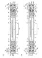
- (A) is a cross-sectional view showing a modified example in which a first steering angle changing tube and a second steering angle changing tube are connected
- (B) is a steering angle changing cylinder device formed of one cylinder. Sectional drawing which shows another example of change.
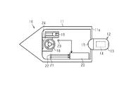
- the ship 10 has a hull 11 and an outboard motor propulsion unit 12 mounted outside the hull 11.
- the outboard motor propulsion unit 12 includes a case 13, an internal combustion engine 14, a steering unit 15, and a turning unit 16.
- the internal combustion engine 14 is housed in the case 13.
- the case 13 is attached to the stern 11e of the hull 11 via a bracket 17.
- the steering unit 15 is attached to the lower part of the case 13.
- the turning unit 16 is attached to the lower portion of the steering unit 15.
- the turning unit 16 can turn with respect to the steering unit 15.
- the turning unit 16 has a propeller 16a.
- the propeller 16a is rotated by the driving force of the internal combustion engine 14.
- the propelling force of the ship 10 is generated by the rotation of the propeller 16a. Therefore, the internal combustion engine 14 is a power source of the marine vessel 10 for generating the propulsive force of the marine vessel 10.
- the boat 10 includes a steering wheel 18, an accelerator lever 19, and a control device 20.
- the steering wheel 18 and the accelerator lever 19 are provided in the operator's cab inside the hull 11. Further, the control device 20 is mounted inside the hull 11.
- the boat 10 also includes a speed sensor 21 that detects the boat speed, an angle sensor 22 that detects the operation amount of the steering wheel 18, and a position sensor 23 that detects the position of the accelerator lever 19.
- the control device 20 is electrically connected to each of the speed sensor 21, the angle sensor 22, and the position sensor 23.
- Information about the boat speed detected by the speed sensor 21 is transmitted to the control device 20.
- Information regarding the operation amount of the steering wheel 18 detected by the angle sensor 22 is transmitted to the control device 20.
- a program for calculating the steering angle of the outboard motor propulsion unit 12 based on the operation amount of the steering wheel 18 transmitted from the angle sensor 22 is stored in the control device 20 in advance.
- Information regarding the position of the accelerator lever 19 detected by the position sensor 23 is transmitted to the control device 20.
- the ship 10 also has a display 24.
- the display 24 is provided, for example, in the operator's cab inside the hull 11.
- the display 24 is electrically connected to the control device 20.
- the display 24 displays information regarding the operation of the ship 10.
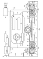
- the boat 10 includes a boat steering device 30 that steers the outboard motor propulsion unit 12.
- the marine vessel steering device 30 includes a steering angle changing cylinder device 25.
- the steering angle changing cylinder device 25 includes a first steering angle changing cylinder 31 and a second steering angle changing cylinder 41.
- the marine vessel steering device 30 includes a first steering angle limiting cylinder 51 and a second steering angle limiting cylinder 61, which are a pair of steering angle limiting cylinders.
- the marine vessel steering device 30 includes a rack and pinion mechanism 71, a first hydraulic pump 81, an oil tank 82, a second hydraulic pump 83, and a switching valve 84.
- the first steering angle changing cylinder 31 has a bottomed tubular first steering angle changing tube 32 and a flat plate-shaped first steering angle changing piston 33.
- the first steering angle changing tube 32 has a flat bottom wall 32a and a tubular peripheral wall 32b extending from the outer peripheral portion of the bottom wall 32a in the axial direction of the first steering angle changing tube 32. ..
- the first steering angle changing piston 33 is housed in the first steering angle changing tube 32 so as to be capable of reciprocating in the first steering angle changing tube 32.
- a first cylinder chamber 34 as a cylinder chamber defined by the first steering angle changing piston 33, the bottom wall 32a, and the peripheral wall 32b is formed.
- the first cylinder chamber 34 is filled with oil as working oil.
- a first steering angle changing oil supply/discharge hole 35 communicating with the first cylinder chamber 34 is formed at an end portion of the peripheral wall 32b adjacent to the bottom wall 32a. Further, a through hole 36 penetrating the bottom wall 32a is formed in the central portion of the bottom wall 32a. The axis of the through hole 36 matches the axis of the peripheral wall 32b.
- the second steering angle changing cylinder 41 has a bottomed tubular second steering angle changing tube 42 and a flat plate-shaped second steering angle changing piston 43.
- the second steering angle changing tube 42 has a flat bottom wall 42a and a cylindrical peripheral wall 42b extending from the outer peripheral portion of the bottom wall 42a in the axial direction of the second steering angle changing tube 42. ..
- the second steering angle changing piston 43 is housed in the second steering angle changing tube 42 so as to be capable of reciprocating in the second steering angle changing tube 42.
- a second cylinder chamber 44 which is a cylinder chamber defined by the second steering angle changing piston 43, the bottom wall 42a, and the peripheral wall 42b, is formed in the second steering angle changing tube 42.
- the steering angle changing cylinder device 25 has a pair of cylinder chambers 34 and 44.
- the second cylinder chamber 44 is filled with oil as working oil.
- a second steering angle changing oil supply/discharge hole 45 communicating with the second cylinder chamber 44 is formed at an end of the peripheral wall 42b adjacent to the bottom wall 42a.
- a through hole 46 penetrating the bottom wall 42a is formed in the center of the bottom wall 42a. The axial center of the through hole 46 coincides with the axial center of the peripheral wall 42b.
- the first steering angle changing tube 32 and the second steering angle changing tube 42 are arranged so that their respective axial directions coincide with each other.
- the first steering angle changing tube 32 and the second steering angle changing tube 42 are arranged such that their openings face each other in the axial direction of the first steering angle changing tube 32 and the second steering angle changing tube 42, respectively.
- the first steering angle changing tube 32 and the second steering angle changing tube 42 are in a state in which their openings are separated from each other in the axial direction of the first steering angle changing tube 32 and the second steering angle changing tube 42, respectively. It is arranged.
- the first steering angle changing tube 32 and the second steering angle changing tube 42 have the same shape. Further, the first steering angle changing piston 33 and the second steering angle changing piston 43 have the same shape.
- the rack and pinion mechanism 71 has an elongated plate-shaped rack 72 and a pinion 73 that is a circular gear.
- a plurality of rack teeth 72 a are provided on one surface of the rack 72.
- the pinion 73 is meshed with the rack teeth 72a.
- a cylindrical connecting shaft 73a is connected to the inner peripheral portion of the pinion 73.
- One end of the connecting shaft 73a is connected to the pinion 73, and the other end of the connecting shaft 73a is connected to the turning unit 16.
- the one end in the longitudinal direction of the rack 72 is inserted into the first steering angle changing tube 32 through the opening of the first steering angle changing tube 32.
- a first steering angle changing piston 33 is connected to a first end of the rack 72 in the longitudinal direction.
- the other end in the longitudinal direction of the rack 72 that is, the second end, enters the second steering angle changing tube 42 through the opening of the second steering angle changing tube 42.
- the second steering angle changing piston 43 is connected to the second end of the rack 72 in the longitudinal direction. Therefore, the rack 72 of the rack-and-pinion mechanism 71 connects the first steering angle changing piston 33 and the second steering angle changing piston 43.
- the pinion 73 is arranged between the opening end of the first steering angle changing tube 32 and the opening end of the second steering angle changing tube 42.
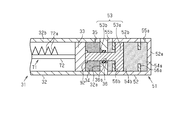
- the first steering angle limiting cylinder 51 has a bottomed tubular first steering angle limiting tube 52 and a first steering angle limiting piston 53.
- the first steering angle limiting tube 52 has a flat bottom wall 52a and a tubular peripheral wall 52b extending from the outer peripheral portion of the bottom wall 52a in the axial direction of the first steering angle limiting tube 52. ..
- the tip of the peripheral wall 52b is connected to the outer surface of the bottom wall 32a of the first steering angle changing tube 32.
- the opening of the first steering angle limiting tube 52 is closed by the bottom wall 32a of the first steering angle changing tube 32.
- the first steering angle limiting tube 52 is connected to the first steering angle changing tube 32 in a state where the axis of the peripheral wall 52b matches the axis of the peripheral wall 32b of the first steering angle changing tube 32.
- the first steering angle limiting piston 53 includes a first piston portion 53a as a piston portion housed in the first steering angle limiting tube 52 and a rod portion provided so as to project from the first piston portion 53a. And a first rod portion 53b.
- the first piston portion 53a has a flat plate shape and is housed in the first steering angle limiting tube 52 so as to be capable of reciprocating in the first steering angle limiting tube 52.
- the first piston portion 53a slides in the first steering angle limiting cylinder 51.
- the first rod portion 53b projects from the central portion of the first piston portion 53a and penetrates the through hole 36 of the bottom wall 32a of the first steering angle changing tube 32.
- the first rod portion 53b can be retracted into the first cylinder chamber 34 of the first steering angle changing cylinder 31 via the through hole 36 in accordance with the reciprocating movement of the first piston portion 53a.
- a first steering angle limiting pressure action chamber 54a defined by a first piston portion 53a, a bottom wall 52a, and a peripheral wall 52b is formed.
- a first piston angle 53a, a peripheral wall 52b, and a first steering angle restoring pressure action chamber 54b defined by a bottom wall 32a of the first steering angle changing tube 32. are formed.
- a first oil supply/discharge hole 55a communicating with the first steering angle limiting pressure action chamber 54a is formed at an end of the peripheral wall 52b adjacent to the bottom wall 52a.
- a second oil supply/discharge hole 55b communicating with the first steering angle returning pressure working chamber 54b is formed at the tip of the peripheral wall 52b.
- a first seal member 36s is provided between the through hole 36 and the first rod portion 53b.
- the first seal member 36s suppresses the flow of oil between the first cylinder chamber 34 and the first steering angle restoring pressure action chamber 54b via the through hole 36 and the first rod portion 53b.
- a first stopper member 56a is attached to a portion of the inner peripheral surface of the peripheral wall 52b closer to the tip than the first oil supply/discharge hole 55a.
- the first stopper member 56a has a thin flat plate ring shape.
- the first stopper member 56a is arranged at a position where the surface of the first stopper member 56a facing the bottom wall 52a is continuous with a part of the inner peripheral surface of the first oil supply/discharge hole 55a.
- the second stopper member 56b is attached to the inner peripheral surface of the peripheral wall 52b at a position closer to the bottom wall 52a than the second oil supply/drain hole 55b and closer to the tip than the first stopper member 56a. There is.
- the second stopper member 56b has a thin flat plate ring shape.
- the second stopper member 56b has the same shape as the first stopper member 56a.
- the second stopper member 56b is arranged at a position where the surface of the second stopper member 56b located on the tip side of the peripheral wall 52b is continuous with a part of the inner peripheral surface of the second oil supply/discharge hole 55b.
- the first piston portion 53a is housed in the first steering angle limiting tube 52 such that the first piston portion 53a can reciprocate in the first steering angle limiting tube 52 between the first stopper member 56a and the second stopper member 56b. .. Therefore, the first stopper member 56a and the second stopper member 56b are stopper members that limit the stroke range of the first steering angle limiting piston 53.
- the second steering angle limiting cylinder 61 has a bottomed tubular second steering angle limiting tube 62 and a second steering angle limiting piston 63.
- the second steering angle limiting tube 62 has a flat bottom wall 62a and a cylindrical peripheral wall 62b extending from the outer peripheral portion of the bottom wall 62a in the axial direction of the second steering angle limiting tube 62. ..
- the tip of the peripheral wall 62b is connected to the outer surface of the bottom wall 42a of the second steering angle changing tube 42.
- the opening of the second steering angle limiting tube 62 is closed by the bottom wall 42a of the second steering angle changing tube 42.
- the second steering angle limiting tube 62 is connected to the second steering angle changing tube 42 in a state where the axis of the peripheral wall 62b matches the axis of the peripheral wall 42b of the second steering angle changing tube 42.
- the second steering angle limiting piston 63 is a second piston portion 63a as a piston portion housed in the second steering angle limiting tube 62, and a rod portion provided so as to project from the second piston portion 63a. And a second rod portion 63b.
- the second piston portion 63a has a flat plate shape and is accommodated in the second steering angle limiting tube 62 so as to be capable of reciprocating in the second steering angle limiting tube 62.
- the second piston portion 63a slides in the second steering angle limiting cylinder 61.
- the second rod portion 63b projects from the central portion of the second piston portion 63a and penetrates the through hole 46 of the bottom wall 42a of the second steering angle changing tube 42. Then, the second rod portion 63b can be retracted into the second cylinder chamber 44 of the second steering angle changing cylinder 41 via the through hole 46 in accordance with the reciprocating movement of the second piston portion 63a.
- a second steering angle limiting pressure action chamber 64a defined by the second piston portion 63a, the bottom wall 62a, and the peripheral wall 62b is formed.
- a second piston angle 63a, a peripheral wall 62b, and a second steering angle restoring pressure action chamber 64b defined by a bottom wall 42a of the second steering angle changing tube 42. are formed.
- a third oil supply/discharge hole 65a communicating with the second steering angle limiting pressure action chamber 64a is formed at an end of the peripheral wall 62b adjacent to the bottom wall 62a.
- a fourth oil supply/discharge hole 65b communicating with the second steering angle returning pressure action chamber 64b is formed at the tip of the peripheral wall 62b.
- a second seal member 46s is provided between the through hole 46 and the second rod portion 63b.
- the second seal member 46s suppresses the flow of oil between the second cylinder chamber 44 and the second steering angle restoring pressure action chamber 64b via the through hole 46 and the second rod portion 63b.
- a third stopper member 66a is attached to a portion of the inner peripheral surface of the peripheral wall 62b closer to the tip than the third oil supply/discharge hole 65a.
- the third stopper member 66a has a thin flat plate ring shape.
- the third stopper member 66a is arranged at a position where the surface of the third stopper member 66a facing the bottom wall 62a is continuous with a part of the inner peripheral surface of the third oil supply/discharge hole 65a.
- the fourth stopper member 66b is attached to the inner peripheral surface of the peripheral wall 62b at a position closer to the bottom wall 62a than the fourth oil supply/discharge hole 65b and closer to the tip than the third stopper member 66a. There is.
- the fourth stopper member 66b has a thin flat plate ring shape.
- the fourth stopper member 66b has the same shape as the third stopper member 66a.
- the fourth stopper member 66b is arranged at a position where the surface of the fourth stopper member 66b located on the tip side of the peripheral wall 62b is continuous with a part of the inner peripheral surface of the fourth oil supply/discharge hole 65b.
- the second piston portion 63a is housed in the second steering angle limiting tube 62 such that the second piston portion 63a can reciprocate in the second steering angle limiting tube 62 between the third stopper member 66a and the fourth stopper member 66b. .. Therefore, the third stopper member 66a and the fourth stopper member 66b are stopper members that limit the stroke range of the second steering angle limiting piston 63.
- the first steering angle limiting tube 52 and the second steering angle limiting tube 62 have the same shape.
- the first steering angle limiting piston 53 and the second steering angle limiting piston 63 have the same shape.
- the distance between the first stopper member 56a and the second stopper member 56b and the distance between the third stopper member 66a and the fourth stopper member 66b are the same.
- the first hydraulic pump 81 is mounted on the hull 11.
- the first hydraulic pump 81 is connected to the steering wheel 18.
- the first hydraulic pump 81 is a helm pump that is driven based on the operation of the steering wheel 18.
- the marine vessel steering device 30 includes a first steering angle changing oil flow passage 81 a that connects the first hydraulic pump 81 and the first steering angle changing oil supply/discharge hole 35.
- the marine vessel steering device 30 includes a second steering angle changing oil flow passage 81b that connects the first hydraulic pump 81 and the second steering angle changing oil supply/discharge hole 45.
- the first steering angle changing oil flow passage 81a and the second steering angle changing oil flow passage 81b are each configured by a pipe, for example. Then, oil is supplied from the first hydraulic pump 81 to the first cylinder chamber 34 and the second cylinder chamber 44 in accordance with the operation amount of the steering wheel 18.
- the first hydraulic pump 81 rotates normally. Then, the first hydraulic pump 81 causes the oil in the first cylinder chamber 34 to pass through the first steering angle changing oil supply/discharge hole 35, the first steering angle changing oil flow passage 81 a, the first hydraulic pump 81, and the second hydraulic pump 81. The oil is supplied into the second cylinder chamber 44 through the steering angle changing oil flow passage 81b and the second steering angle changing oil supply/discharge hole 45.
- the hydraulic pressure in the second cylinder chamber 44 overcomes the hydraulic pressure in the first cylinder chamber 34, the second steering angle changing piston 43 moves in a direction away from the bottom wall 42a, and the first steering angle changing
- the operating piston 33 moves in a direction approaching the bottom wall 32a, and the rack 72 moves in a direction retracting into the first steering angle changing tube 32.
- the rack 72 moves in a direction retracting into the first steering angle changing tube 32.
- the pinion 73 meshed with the rack tooth 72a rotates counterclockwise, and the turning unit 16 moves the connecting shaft 73a. Turn left through.
- the traveling direction of the ship 10 is changed to the right.
- the first hydraulic pump 81 reverses.
- the first hydraulic pump 81 transfers the oil in the second cylinder chamber 44 to the second steering angle changing oil supply/discharge hole 45, the second steering angle changing oil flow passage 81b, the first hydraulic pump 81, and the first hydraulic pump 81.
- the oil is supplied into the first cylinder chamber 34 through the steering angle changing oil flow passage 81a and the first steering angle changing oil supply/discharge hole 35.
- the hydraulic pressure in the first cylinder chamber 34 overcomes the hydraulic pressure in the second cylinder chamber 44, the first steering angle changing piston 33 moves in a direction away from the bottom wall 32a, and the second steering angle changing is performed.
- the working piston 43 moves in a direction approaching the bottom wall 42a, and the rack 72 moves in a direction retracting into the second steering angle changing tube 42.
- the rack 72 moves in a direction retracting into the second steering angle changing tube 42.
- the pinion 73 meshed with the rack tooth 72a rotates clockwise, and the turning unit 16 moves the connecting shaft 73a. Turn right through. As a result, the traveling direction of the ship 10 is changed to the left.
- the steering angle to the left in the turning unit 16 that is, the clockwise steering angle of the ship 10 becomes the maximum angle.
- the movement of the first steering angle changing piston 33 until it comes into contact with the bottom wall 32a is the movement of the first steering angle changing piston 33 to the stroke end.
- the distance between the first steering angle changing piston 33 and the bottom wall 32a and the distance between the second steering angle changing piston 43 and the bottom wall 42a are increased.
- the steering angle to the right in the turning unit 16 that is, the counterclockwise steering angle of the ship 10 increases.
- the steering angle to the right in the turning unit 16 that is, the counterclockwise steering angle of the ship 10 becomes the maximum angle.
- the movement of the second steering angle changing piston 43 until it comes into contact with the bottom wall 42a is the movement of the second steering angle changing piston 43 to the stroke end.
- the maximum steering angle of the turning unit 16 as shown in FIG. 1 is, for example, ⁇ 90 degrees.
- the first steering angle changing piston 33 and the second steering angle changing piston 43 are arranged in the first cylinder chamber 34 and the second cylinder chamber 34 in order to change the steering angle of the turning unit 16, that is, the outboard motor propulsion unit 12.
- the pair of steering angle changing pistons reciprocates in the first steering angle changing cylinder 31 and the second steering angle changing cylinder 41 by the hydraulic pressure in the chamber 44.
- the rack and pinion mechanism 71 is driven by the reciprocating movement of the first steering angle changing piston 33 and the second steering angle changing piston 43 to change the steering angle of the outboard motor propulsion unit 12.
- the marine steering device 30 includes a first connection flow path 85 that connects the oil tank 82 and the second hydraulic pump 83.
- the marine vessel steering apparatus 30 also includes a second connection flow path 86 that connects the second hydraulic pump 83 and the switching valve 84.
- the marine vessel steering device 30 includes a third connection flow path 87 that connects the switching valve 84 and the oil tank 82.
- the first connection flow path 85, the second connection flow path 86, and the third connection flow path 87 are each configured by piping, for example.
- the marine vessel steering device 30 includes a first steering angle limiting oil passage 84a that connects the switching valve 84 and the first oil supply/discharge hole 55a. Further, the marine vessel steering device 30 includes a second steering angle limiting oil passage 84b that connects the switching valve 84 and the second oil supply/discharge hole 55b. The marine vessel steering device 30 includes a third steering angle limiting oil passage 84c that connects the first steering angle limiting oil passage 84a and the third oil supply/discharge hole 65a. The marine vessel steering device 30 also includes a fourth steering angle limiting oil passage 84d that connects the second steering angle limiting oil passage 84b and the fourth oil supply/discharge hole 65b.
- Reference numeral 84d constitutes a hydraulic pipe 88 that connects the second hydraulic pump 83 to the first steering angle limiting cylinder 51 and the second steering angle limiting cylinder 61.
- the switching valve 84 is provided on the hydraulic pipe 88.
- the oil as the hydraulic oil is stored in the oil tank 82.
- the second hydraulic pump 83 is driven by the power of the internal combustion engine 14. Then, when the second hydraulic pump 83 is driven by the power of the internal combustion engine 14, the oil stored in the oil tank 82 flows through the first connection flow path 85, the second hydraulic pump 83, and the second connection flow path 86. It is supplied to the switching valve 84 via the.
- the switching valve 84 is electrically connected to the control device 20.
- the switching valve 84 is an electromagnetic valve that operates based on a command signal output from the control device 20.
- a program for generating a command signal for operating the switching valve 84 is stored in the control device 20 in advance.
- the command signal for operating the switching valve 84 is generated from information regarding the operation amount of the steering wheel 18, the position of the accelerator lever 19, and the boat speed.
- the switching valve 84 allows the oil supplied from the second hydraulic pump 83 via the second connection flow path 86 to the first steering angle restriction oil flow path 84a, and also allows the second steering angle restriction oil to flow. It is configured to be switchable to a first valve switching state that allows the flow of oil from the flow path 84b to the third connection flow path 87. Further, the switching valve 84 allows the flow of oil supplied from the second hydraulic pump 83 via the second connection flow path 86 to the second steering angle restriction oil flow path 84b, and also allows the first steering angle restriction to be performed. It is configured to be switchable to a second valve switching state that allows the flow of oil from the oil passage 84a for use to the third connection passage 87.
- the switching valve 84 is provided to the first steering angle limiting oil flow passage 84a and the second steering angle limiting oil flow passage 84b in the oil supplied from the second hydraulic pump 83 via the second connection flow passage 86, respectively. Is shut off and the oil supplied from the second connection flow path 86 is allowed to flow to the third connection flow path 87.
- the switching valve 84 is configured to be switchable to three valve switching states of a first valve switching state, a second valve switching state, and a third valve switching state by a command signal from the control device 20.
- the control device 20 stores in advance a program for executing the steering angle unrestricted mode execution processing. In addition, the control device 20 stores in advance a program for performing the steering angle limited mode execution process. Further, the control device 20 stores in advance a program for performing a determination process as to whether or not to perform the steering angle limited mode execution process.
- the control device 20 determines that the steering angle limited mode execution process is performed during the steering angle limited mode execution process, and the steering angle limited mode execution process is performed from the steering angle limited mode execution process.
- the operation of the switching valve 84 is controlled so that the switching valve 84 switches to the first valve switching state. Then, the flow of the oil supplied from the second hydraulic pump 83 to the switching valve 84 via the second connection passage 86 to the first steering angle limiting oil passage 84a is allowed, and the second steering angle limiting oil passage 84a is allowed.
- the flow of oil from the oil flow path 84b to the third connection flow path 87 via the switching valve 84 is allowed.
- the first steering angle restriction Oil is supplied into the first steering angle limiting pressure action chamber 54a through the oil passage 84a and the first oil supply/discharge hole 55a.
- the first piston portion 53a moves from the first stopper member 56a toward the second stopper member 56b in response to the hydraulic pressure in the first steering angle limiting pressure action chamber 54a, and the first rod portion 53b penetrates the first piston portion 53a. It projects into the first steering angle changing cylinder 31 through the hole 36.
- the oil in the first steering angle returning pressure working chamber 54b is transferred to the second oil supply/discharge hole 55b and the second oil supply/discharge hole 55b.
- the oil is returned to the oil tank 82 via the 2 steering angle limiting oil flow passage 84b, the switching valve 84, and the third connection flow passage 87.
- the first steering angle limiting oil flow passage 84a when the oil supplied from the second hydraulic pump 83 to the switching valve 84 via the second connection flow passage 86 flows to the first steering angle limiting oil flow passage 84a, the first steering angle limiting oil flow passage 84a. Oil is supplied into the second steering angle limiting pressure action chamber 64a through the third steering angle limiting oil flow path 84c and the third oil supply/discharge hole 65a. Then, the second piston portion 63a moves from the third stopper member 66a to the fourth stopper member 66b in response to the hydraulic pressure in the second steering angle limiting pressure action chamber 64a, and the second rod portion 63b penetrates the second piston portion 63a. It projects into the second steering angle changing cylinder 41 through the hole 46.
- the oil in the second steering angle returning pressure working chamber 64b is transferred to the fourth oil supply/discharge hole 65b and the fourth oil supply/discharge hole 65b.
- the oil is returned to the oil tank 82 via the fourth steering angle limiting oil flow passage 84d, the second steering angle limiting oil flow passage 84b, the switching valve 84, and the third connection flow passage 87.
- the movement of the first piston portion 53a from the first stopper member 56a to the second stopper member 56b and the movement of the second piston portion 63a from the third stopper member 66a to the fourth stopper member 66b are synchronized. Done. Therefore, the time when the first piston portion 53a is separated from the first stopper member 56a and the time when the second piston portion 63a is separated from the third stopper member 66a are the same timing. Further, the timing of contacting the second stopper member 56b of the first piston portion 53a and the timing of contacting the fourth stopper member 66b of the second piston portion 63a are the same timing.
- the time required is the same.
- the first rod portion 53b protruding into the first steering angle changing cylinder 31 comes into contact with the first steering angle changing piston 33 to restrict the movement of the first steering angle changing piston 33 to the stroke end. .. Therefore, during the steering angle limited mode execution process, the first steering angle changing piston 33 does not contact the bottom wall 32a, so that the steering angle of the turning unit 16 to the left, that is, the steering angle to the right of the ship 10 is increased. It will be in a restricted state.
- the second rod portion 63b protruding into the second steering angle changing cylinder 41 abuts on the second steering angle changing piston 43, thereby moving the second steering angle changing piston 43 to the stroke end. regulate. Therefore, during the steering angle limited mode execution process, the second steering angle changing piston 43 does not contact the bottom wall 42a, so that the steering angle of the turning unit 16 in the right direction, that is, the counterclockwise steering angle of the ship 10 is reduced. It will be in a restricted state.
- the first steering angle limiting piston 53 and the second steering angle limiting piston 63 have the first steering angle limiting tube 52 and the first steering angle limiting tube 52 and 2 A steering angle limiting piston that reciprocates inside each of the steering angle limiting tubes 62.
- the control device 20 causes the switching valve 84 to switch to the third valve switching state when the first piston portion 53a contacts the second stopper member 56b and the second piston portion 63a contacts the fourth stopper member 66b.
- the operation of the switching valve 84 is controlled.
- the oil supplied from the second hydraulic pump 83 to the switching valve 84 via the second connection flow path 86 flows to the first steering angle limiting oil flow path 84a and the second steering angle limiting oil flow path 84b, respectively.
- the flow is blocked, and the flow of the oil supplied from the second connecting passage 86 to the switching valve 84 to the third connecting passage 87 is allowed.
- the oil supplied from the second hydraulic pump 83 to the switching valve 84 via the second connection flow path 86 is returned to the oil tank 82 via the third connection flow path 87.
- the control device 20 determines by the determination process that the steering angle limited mode execution process is performed, and the steering angle limited mode execution process is performed.
- the operation of the switching valve 84 is controlled so that the switching valve 84 switches to the second valve switching state. Then, the flow of the oil supplied from the second hydraulic pump 83 to the switching valve 84 via the second connection passage 86 to the second steering angle limiting oil passage 84b is allowed, and the first steering angle limiting oil passage 84b is allowed.
- the flow of oil from the oil flow path 84a to the third connection flow path 87 via the switching valve 84 is allowed.
- the oil in the first steering angle limiting pressure action chamber 54a is transferred to the first oil supply/discharge hole 55a and the first oil supply/discharge hole 55a.
- the oil is returned to the oil tank 82 through the 1-steering-angle limiting oil passage 84 a, the switching valve 84, and the third connecting passage 87.
- the second steering angle limiting oil flow passage 84b when the oil supplied from the second hydraulic pump 83 to the switching valve 84 via the second connection flow passage 86 flows to the second steering angle limiting oil flow passage 84b, the second steering angle limiting oil flow passage 84b. Oil is supplied into the second steering angle returning pressure action chamber 64b through the fourth steering angle limiting oil flow path 84d and the fourth oil supply/discharge hole 65b. Then, the second piston portion 63a receives the hydraulic pressure in the second steering angle returning pressure working chamber 64b to move from the fourth stopper member 66b toward the third stopper member 66a, and the second rod portion 63b moves. Immerse into the second steering angle changing cylinder 41.
- the oil in the second steering angle limiting pressure action chamber 64a is transferred to the third oil supply/discharge hole 65a and the third oil supply/discharge hole 65a.
- the oil is returned to the oil tank 82 through the third steering angle limiting oil flow passage 84c, the first steering angle limiting oil flow passage 84a, the switching valve 84, and the third connection flow passage 87.
- the movement of the first piston portion 53a from the second stopper member 56b toward the first stopper member 56a and the movement of the second piston portion 63a from the fourth stopper member 66b toward the third stopper member 66a are synchronized. Done. Therefore, the time when the first piston portion 53a is separated from the second stopper member 56b and the time when the second piston portion 63a is separated from the fourth stopper member 66b are the same timing. Further, the timing of contacting the first stopper member 56a of the first piston portion 53a and the timing of contacting the third stopper member 66a of the second piston portion 63a are the same timing.
- the tip of the first rod portion 53b is in a state of not protruding from the through hole 36 into the first steering angle changing cylinder 31. Therefore, the first rod portion 53b recessed in the first steering angle changing cylinder 31 allows the first steering angle changing piston 33 to move to the stroke end. Therefore, during the steering angle non-limitation mode execution process, the first steering angle changing piston 33 can contact the bottom wall 32a, so that the steering angle of the turning unit 16 to the left, that is, the steering angle to the right of the ship 10 is increased. The restriction of is released.
- the second hydraulic pump 83 supplies and discharges oil to and from the first steering angle limiting cylinder 51 and the second steering angle limiting cylinder 61, respectively, to supply the first steering angle limiting piston 53 and the second steering angle limiting piston.
- 63 are reciprocated.
- the switching valve 84 allows the first steering angle limiting piston 53 and the second steering angle limiting piston 63 to move to the stroke end of the first steering angle changing piston 33 and the second steering angle changing piston 43. Perform the operation to switch to the allowable state. Further, the switching valve 84 moves the first steering angle limiting piston 53 and the second steering angle limiting piston 63 to the stroke end of the first steering angle changing piston 33 and the second steering angle changing piston 43. Performs the operation of switching to the regulated state.
- the switching valve 84 operates to switch between the allowable state and the restricted state, and the first steering angle limiting piston 53 and the second steering angle limiting piston 63 operate in the allowable state and the restricted state. It can be switched between and. Then, the switching valve 84 switches the supply and discharge of oil to and from the first steering angle limiting cylinder 51 and the second steering angle limiting cylinder 61 in the second hydraulic pump 83. Therefore, the first steering angle limiting cylinder 51 and the second steering angle limiting cylinder 61 are double-acting cylinders.
- the control device 20 switches so that the switching valve 84 switches to the third valve switching state when the first piston portion 53a contacts the first stopper member 56a and the second piston portion 63a contacts the third stopper member 66a. Controls the operation of valve 84. Then, the oil supplied from the second hydraulic pump 83 to the switching valve 84 via the second connection flow path 86 flows to the first steering angle limiting oil flow path 84a and the second steering angle limiting oil flow path 84b, respectively. The flow is blocked, and the flow of the oil supplied from the second connecting passage 86 to the switching valve 84 to the third connecting passage 87 is allowed. As a result, the oil supplied from the second hydraulic pump 83 to the switching valve 84 via the second connection flow path 86 is returned to the oil tank 82 via the third connection flow path 87.
- the control device 20 stores a steering angle limit value ⁇ , a steering angle limit applicable ship speed V, and a steering angle limit piston operation completion time T as preset parameters.
- the steering angle limit value ⁇ is an upper limit value of the steering angle of the outboard motor propulsion unit 12 that is allowed when the control device 20 is executing the steering angle limited mode. For example, when the first steering angle changing piston 33 and the first rod portion 53b come into contact with each other in the state where the first piston portion 53a comes into contact with the second stopper member 56b, the outboard motor propulsion unit 12 moves leftward. The steering angle becomes the steering angle limit value ⁇ .
- the right outboard motor propulsion unit 12 has The steering angle in the direction becomes the steering angle limit value ⁇ .
- the steering angle limit application speed V is a predetermined ship speed, and is used to determine whether or not to execute the steering angle limit mode execution process while the control device 20 is executing the determination process. Then, when the boat speed increases and becomes equal to or higher than the steering angle limit applicable speed V, the control device 20 causes the first rod portion 53b and the second rod portion 63b to move the first steering angle changing cylinder 31 and the second steering angle.
- a program for controlling the operation of the switching valve 84 so as to be projected into the changing cylinder 41 is stored in advance.
- the first steering angle limiting piston 53 and the second steering angle limiting piston 63 are configured such that, when the boat speed increases and becomes equal to or higher than the steering angle limiting applied speed V, the first steering angle changing piston 33 and the second steering angle limiting piston 33. It operates so as to switch from an allowable state in which the movement of the changing piston 43 to the stroke end is permitted to a regulation state in which the movement to the stroke end is regulated.
- the control device 20 is a control unit that controls the operation of the switching valve 84 according to the boat speed.
- the steering angle limiting piston operation completion time T is the time required for the first piston portion 53a to move from the first stopper member 56a to the second stopper member 56b, or the first piston portion 53a moves from the second stopper member 56b to the second stopper member 56b. This is the time required to move to the first stopper member 56a.
- the steering angle limiting piston operation completion time T is the time required for the second piston portion 63a to move from the third stopper member 66a to the fourth stopper member 66b, or the second piston portion 63a is the fourth stopper member 66b. It is also the time required to move from to the third stopper member 66a.
- the first rod portion 53b and the second rod portion 63b cause the first steering angle changing cylinder 31 and the second steering angle changing.
- a program for controlling the operation of the switching valve 84 so as to be projected into each of the use cylinders 41 is stored in advance. Therefore, the first steering angle limiting piston 53 and the second steering angle limiting piston 63 have the first steering angle changing piston 33 and the second steering angle changing when the accelerator lever 19 is held at the accelerator fully open position. It operates so as to switch from a permissible state in which the movement of the working piston 43 to the stroke end is permitted to a regulation state in which the movement to the stroke end is regulated.
- the first steering angle limiting piston 53 and the second steering angle limiting piston 63 are configured such that when the boat speed is equal to or higher than the steering angle limiting applied speed V, the first steering angle changing piston 33 and the second steering angle changing piston are used. It is at least operated so as to be in a restricted state in which the movement of the changing piston 43 to the stroke end is restricted.
- the control device 20 also has a timer function for measuring time when the first piston portion 53a and the second piston portion 63a start moving.
- a program for the control device 20 to measure the movement time of the first piston portion 53a and the second piston portion 63a as the steering angle change elapsed time when the first piston portion 53a and the second piston portion 63a start to move. Is stored in advance.
- the control device 20 first performs initial setting in step S11. As an initial setting, the control device 20 performs the steering angle no limit mode execution processing, sets the steering angle change elapsed time to “0”, and further sets the steering angle limit excess flag to “0”. Next, in step S12, the control device 20 causes the information about the boat speed detected by the speed sensor 21, the information about the operation amount of the steering wheel 18 detected by the angle sensor 22, and the accelerator lever detected by the position sensor 23. Each receives information about 19 locations.
- step S13 the control device 20 determines whether or not the boat speed detected by the speed sensor 21 is equal to or higher than the steering angle limit applicable speed V.
- the control device 20 determines in step S13 that the boat speed is not equal to or higher than the steering angle limit applicable speed V
- the control device 20 proceeds to step S14, and the position of the accelerator lever 19 detected by the position sensor 23 in step S14 is the accelerator fully open position. Determine if there is.
- the control device 20 determines in step S14 that the position of the accelerator lever 19 is not the accelerator fully open position, the control device 20 proceeds to step S15 and determines in step S15 whether or not the steering angle limited mode execution process is being performed.
- step S15 When the control device 20 determines in step S15 that the steering angle limited mode execution process is being performed, the control device 20 proceeds to step S16 and sets the steering angle change elapsed time to "0" in step S16. Then, the control device 20 performs the steering angle unrestricted mode execution processing in step S17. On the other hand, when the control device 20 determines in step S15 that the steering angle limited mode execution process is not performed, the process proceeds to step S17.
- step S18 the control device 20 determines whether or not the steering angle change elapsed time is equal to or greater than the steering angle limiting piston operation completion time T.
- the process proceeds to step S19, and the switching valve 84 is in the second valve switching state in step S19.
- the control device 20 controls the operation of the switching valve 84 so that the switching valve 84 is in the second valve switching state in step S19, and at the same time, measures the steering angle change elapsed time.
- step S20 the control device 20 informs whether the current mode execution processing status is the steering angle restriction non-mode execution processing or the steering angle restriction mode execution processing, and the current steering angle restriction status information. And the steering angle of the outboard motor propulsion unit 12 are output to the display 24. After that, the control device 20 proceeds to step S12 and repeats the processing from step S12.
- step S18 when the control device 20 determines in step S18 that the steering angle change elapsed time is equal to or greater than the steering angle limiting piston operation completion time T, the process proceeds to step S21, and in step S21, the switching valve 84 is in the third valve switching state.
- the operation of the switching valve 84 is controlled so that As a result, the first rod portion 53b is retracted into the first steering angle changing cylinder 31, and the second rod portion 63b is retracted into the second steering angle changing cylinder 41.
- the positions of the limiting piston 53 and the second steering angle limiting piston 63 are held, and the steering angle of the outboard motor propulsion unit 12 is not limited. Then, the control device 20 moves to step S20.
- step S13 determines in step S13 that the boat speed is equal to or higher than the steering angle limit applicable speed V
- the control device 20 proceeds to step S22, and determines whether or not the steering angle no limit mode execution process is performed in step S22. It is determined whether the steering angle limit excess flag is "0".
- step S14 determines in step S14 that the position of the accelerator lever 19 is the accelerator fully open position
- Steps S13 and S14 execute the steering angle limited mode execution process based on the information on the boat speed, the information on the operation amount of the steering wheel 18, and the information on the position of the accelerator lever 19 received by the control device 20 in step S12. This is a determination process in which the control device 20 determines whether or not to perform.
- step S22 When the control device 20 determines in step S22 that the steering angle limit non-execution process is being performed or the steering angle limit excess flag is "0", the control device 20 proceeds to step S23, and in step S23, the steering angle change elapsed time is elapsed. Is set to "0". Then, the control device 20 performs a steering angle limited mode execution process in step S24. On the other hand, if the control device 20 determines in step S22 that the steering angle no limit mode execution processing is not performed or the steering angle limit excess flag is not "0", the process proceeds to step S24.
- step S25 determines in step S25 whether or not the absolute value of the steering angle of the outboard motor propulsion unit 12 is larger than the steering angle limit value ⁇ .
- step S25 determines in step S25 that the absolute value of the steering angle of the outboard motor propulsion unit 12 is larger than the steering angle limit value ⁇ .
- the control device 20 proceeds to step S26, and sets the steering angle limit excess flag to “1” in step S26. Set to.
- step S27 the control device 20 outputs a warning display on the display 24 so that the steering angle of the outboard motor propulsion unit 12 becomes equal to or less than the steering angle limit value ⁇ .
- control device 20 controls the operation of the switching valve 84 so that the switching valve 84 is in the first valve switching state in step S28. Further, the control device 20 controls the operation of the switching valve 84 so that the switching valve 84 is in the first valve switching state in step S28, and at the same time, measures the steering angle change elapsed time. Then, the control device 20 proceeds to step S20, and in step S20, outputs the information regarding the current steering angle restriction state and the current steering angle of the outboard motor propulsion unit 12 to the display 24. After that, the control device 20 proceeds to step S12 and repeats the processing from step S12.
- step S25 when the control device 20 determines in step S25 that the absolute value of the steering angle of the outboard motor propulsion unit 12 is not larger than the steering angle limit value ⁇ , the control device 20 proceeds to step S29, and in step S29, the steering angle limit excess flag is set. Is set to "0". Then, in step S30, the control device 20 determines whether or not the steering angle change elapsed time is equal to or greater than the steering angle limiting piston operation completion time T.
- step S30 When it is determined in step S30 that the steering angle change elapsed time is not equal to or longer than the steering angle limiting piston operation completion time T in step S30, the control device 20 proceeds to step S28 and performs the processing of step S28 and thereafter.
- step S30 when it is determined in step S30 that the steering angle change elapsed time is equal to or longer than the steering angle limiting piston operation completion time T, the process proceeds to step S21, and in step S21 the switching valve 84 is switched to the third valve switching state. Control the operation of 84.
- the first rod portion 53b projects into the first steering angle changing cylinder 31
- the second rod portion 63b projects into the second steering angle changing cylinder 41.
- the positions of the piston 53 and the second steering angle limiting piston 63 are held, and the steering angle of the outboard motor propulsion unit 12 is limited.
- the first steering angle limiting piston 53 and the second steering angle limiting piston 63 use the first steering angle changing piston 33 and the second steering angle when the boat speed is equal to or higher than the steering angle limiting applied speed V. It is at least operated so as to be in a restricted state in which the movement of the angle changing piston 43 to the stroke end is restricted. Then, with the movement of the first steering angle changing piston 33 and the second steering angle changing piston 43 to the stroke end restricted, the first steering angle changing piston 33 and the second steering angle changing piston 43 are controlled.
- the outboard motor propulsion unit 12 is steered while the steering angle is limited. Therefore, when the hydraulically driven marine vessel steering device 30 that turns the outboard motor propulsion unit 12 using hydraulic pressure is adopted, the steering angle of the outboard motor propulsion unit 12 is limited when the marine vessel 10 travels at high speed. be able to.
- a first stopper member 56a and a second stopper member 56b for limiting the stroke range of the first steering angle limiting piston 53 are provided in the first steering angle limiting cylinder 51, and the second steering angle
- a third stopper member 66 a and a fourth stopper member 66 b that limit the stroke range of the second steering angle limiting piston 63 are provided in the limiting cylinder 61. According to this, the positions of the first stopper member 56a and the second stopper member 56b provided in the first steering angle limiting cylinder 51 are changed, and the third stopper provided in the second steering angle limiting cylinder 61.
- the limit angle of the steering angle of the outboard motor propulsion unit 12 can be easily adjusted.
- the first steering angle limiting piston 53 and the second steering angle limiting piston 63 have the first steering angle changing piston 33 and the second steering angle when the boat speed increases and becomes equal to or higher than the steering angle limiting applicable speed V. It operates so as to switch from an allowable state in which the movement of the angle changing piston 43 to the stroke end is permitted to a regulation state in which the movement to the stroke end is regulated. According to this, the steering angle of the outboard motor propulsion unit 12 can be reliably limited when the marine vessel 10 is traveling at a ship speed equal to or higher than the steering angle restriction applicable ship speed V.
- the boat 10 accelerates to reach the maximum speed. Therefore, the first steering angle limiting piston 53 and the second steering angle limiting piston 63 change the first steering angle changing piston 33 and the second steering angle changing when the position of the accelerator lever 19 is held at the accelerator fully opened position. It operates so as to switch from an allowable state in which the movement of the working piston 43 to the stroke end is permitted to a regulation state in which the movement to the stroke end is regulated. As a result, the steering angle of the outboard motor propulsion unit 12 can be limited at an early stage.
- the control device 20 controls the operation of the switching valve 84 so that the switching valve 84 is in the third valve switching state, so that the first steering angle limiting piston 53 and the second steering angle limiting piston 63, respectively. Position is retained. As a result, it is possible to prevent the load from being applied to each of the first stopper member 56a, the second stopper member 56b, the third stopper member 66a, and the fourth stopper member 66b.
- the outboard motor propulsion unit 12 can be steered using hydraulic pressure, even when the outboard motor propulsion unit 12 has a large weight.
- the outboard motor propulsion unit 12 can be easily steered.
- the marine vessel steering apparatus 30 of the present embodiment it is not necessary to include a reaction force motor that applies a reaction force to the steering wheel 18 as in the related art, and thus the configuration of the hull 11 is restricted. Can be suppressed.
- the first rod portion 53b has the first steering angle between the bottom wall 52a of the first steering angle limiting tube 52 and the first piston portion 53a of the first steering angle limiting piston 53.
- a tension spring 91 may be provided that urges the first steering angle limiting piston 53 in a direction in which the changing cylinder 31 is retracted. According to this, when the steering angle limited mode execution process is switched to the steering angle limited mode execution process, the urging force of the tension spring 91 causes the first rod portion 53b to move into the first steering angle changing cylinder 31. On the other hand, the first steering angle limiting piston 53 can be smoothly moved in the direction in which it is immersed.
- the second rod portion 63b is provided between the bottom wall 62a of the second steering angle limiting tube 62 and the second piston portion 63a of the second steering angle limiting piston 63 for changing the second steering angle.
- a tension spring 91 may be provided that urges the second steering angle limiting piston 63 in a direction in which the second steering angle limiting piston 63 is retracted into the cylinder 41.
- the first rod portion 53b is the first steering angle changing cylinder between the bottom wall 52a of the first steering angle limiting tube 52 and the first piston portion 53a of the first steering angle limiting piston 53.
- An urging spring that urges the first steering angle limiting piston 53 in a direction projecting into the inside 31 may be provided. According to this, when the steering angle limited mode execution process is switched to the steering angle limited mode execution process, the urging force of the urging spring causes the first rod portion 53b to move into the first steering angle changing cylinder 31. It is possible to smoothly move the first steering angle limiting piston 53 in the protruding direction.
- the second rod portion 63b is provided between the bottom wall 62a of the second steering angle limiting tube 62 and the second piston portion 63a of the second steering angle limiting piston 63 for changing the second steering angle.
- An urging spring that urges the second steering angle limiting piston 63 in the direction of protruding into the cylinder 41 may be provided.
- an annular flange 92 may be provided at the tip of the first rod portion 53b. According to this, as compared with the case where the flange 92 is not provided at the tip of the first rod portion 53b, the contact area with the first steering angle changing piston 33 in the first rod portion 53b becomes large, so that the first The movement of the steering angle changing piston 33 to the stroke end can be easily regulated.
- An annular flange 92 may be provided at the tip of the second rod portion 63b.
- the first stopper member 56a, the second stopper member 56b, the third stopper member 66a, and the fourth stopper member 66b may be omitted in the marine vessel steering device 30.
- the first piston portion 53a moves between the bottom wall 52a of the first steering angle limiting tube 52 and the bottom wall 32a of the first steering angle changing tube 32.
- the second piston portion 63a moves between the bottom wall 62a of the second steering angle limiting tube 62 and the bottom wall 42a of the second steering angle changing tube 42.
- the first oil supply/discharge hole 55a or the second oil supply hole 55a is provided in the state where the first piston portion 53a is in contact with the bottom wall 52a or the state where the first piston portion 53a is in contact with the bottom wall 32a. Notches may be formed on the entire circumference of the corners of the first piston portion 53a so that oil can be easily supplied and discharged from the drain hole 55b. Further, in a state where the second piston portion 63a is in contact with the bottom wall 62a and a state in which the second piston portion 63a is in contact with the bottom wall 42a, the third oil supply/discharge hole 65a or the fourth oil supply/discharge hole 65b. Notches may be formed in the entire circumference of the corners of the second piston portion 63a so that the oil can be easily supplied and drained.
- the position within may be changed appropriately.
- control device 20 controls the first rod portion 53b and the second rod portion 63b in the first steering angle changing cylinder 31 even when the accelerator lever 19 is held at the accelerator fully open position. Also, the operation of the switching valve 84 does not have to be controlled so as to project into the second steering angle changing cylinder 41.
- the marine vessel steering device 30 includes, for example, the hydraulic pressure and the oil temperature in the first steering angle changing cylinder 31 and the second steering angle changing cylinder 41, the first steering angle limiting cylinder 51, and the like.
- Various sensors may be further provided for detecting the hydraulic pressure and oil temperature in each second steering angle limiting cylinder 61, the rotation speed of the internal combustion engine 14, the acceleration of the ship 10, and the like. Then, the control device 20 may control the operation of the switching valve 84 using each parameter in addition to the boat speed. According to this, the operation of the switching valve 84 can be accurately controlled.
- control device 20 outputs the warning display on the display 24 so that the steering angle of the outboard motor propulsion unit 12 is set to the steering angle limit value ⁇ or less in step S27.
- the warning may be given by a lamp, a buzzer, or a voice.
- the marine vessel steering device 30 may include piston position detection sensors that detect the positions of the first steering angle limiting piston 53 and the second steering angle limiting piston 63, respectively. In this case, the control device 20 does not have to measure the moving time of the first piston portion 53a and the second piston portion 63a as the steering angle change elapsed time.
- the maximum steering angle of the outboard motor propulsion unit 12 does not have to be ⁇ 90 degrees, and the maximum steering angle is not particularly limited.
- the first steering angle changing tube 32 and the second steering angle changing tube 42 may be arranged so that their respective openings are connected.
- the opening 26 is provided in the first steering angle changing tube 32
- the opening 27 is provided in the second steering angle changing tube 42.
- the first steering angle changing tube 32 and the second steering angle changing tube 42 may be integrally formed with their openings connected to each other. That is, the steering angle changing cylinder device 25 may be formed by one cylinder.
- the steering angle changing cylinder device 25 has a pair of cylinder chambers, and a pair of steering angle changing pistons reciprocate in the steering angle changing cylinder by the hydraulic pressure in the pair of cylinder chambers. Good.
- the first steering angle limiting cylinder 51 and the second steering angle limiting cylinder 61 are, for example, the first steering angle limiting piston 53 and the return steering spring when the switching from the regulation state to the permission state is performed. It may be a single-acting cylinder that moves each of the second steering angle limiting pistons 63.
- the control device 20 is not limited to one that includes a central processing unit and a memory and executes software processing.
- a dedicated hardware circuit for example, ASIC
- ASIC application-specific integrated circuit
- the control device 20 may have any of the following configurations (a) to (c).
- C A dedicated hardware circuit for executing all of the above processes is provided.
Landscapes
- Chemical & Material Sciences (AREA)
- Engineering & Computer Science (AREA)
- Combustion & Propulsion (AREA)
- Mechanical Engineering (AREA)
- Ocean & Marine Engineering (AREA)
- Actuator (AREA)
Abstract
船舶用操舵装置は、操舵角変更用シリンダ装置、一対の操舵角変更用ピストン、ラックアンドピニオン機構、及び一対の操舵角制限用シリンダを備える。各操舵角制限用ピストンは、各操舵角変更用ピストンのストロークエンドまでの移動を許容する許容状態と、各操舵角変更用ピストンのストロークエンドまでの移動を規制する規制状態との間で切り替え可能である。各操舵角制限用ピストンは、船速が予め定められた操舵角制限適用速度以上である場合には、規制状態となるように少なくとも動作されている。
Description
本開示は、船舶用操舵装置に関する。
従来の船舶用操舵装置として、例えば、船体の外部に搭載された船外機推進ユニットをモータにより操舵するモータ駆動式の操舵装置が知られている。このようなモータ駆動式の操舵装置は、特に小型船舶に採用されている。操舵装置は、操船者のステアリングホイール操作量をセンサによって検出するとともに、モータ制御部がセンサによって検出されたステアリングホイール操作量に基づいてモータの駆動を制御することで船外機推進ユニットの操舵角(旋回量)を制御している。
ところで、船舶が高速で走行している際に、操船者がステアリングホイールを大きく操作した場合、そのステアリングホイール操作量に基づいて船外機推進ユニットの操舵角が制御されると、船舶が大きく急旋回されることになり、船舶の走行安定性が損なわれてしまう虞がある。このため、船舶の高速走行時には、船舶が急旋回しないように船外機推進ユニットの操舵角を制限する必要がある。例えば、特許文献1の船舶用操舵装置には、ステアリングホイールに反力を与える反力モータが設けられる。船舶用操舵装置は、船舶が高速で走行している際には、高速走行時に船外機推進ユニットの操舵角が大きくならないように、反力モータを駆動させて操船者のステアリングホイール操作をし難くしている。
ところで、船体のサイズが大きくなると、船体の外部に取り付けられる船外機推進ユニットも大型のものが必要になり、その結果、船外機推進ユニットの重量が大きくなる。この場合、船外機推進ユニットを旋回させるために必要な力も大きくなるので、モータ駆動式の操舵装置に変えて、油圧駆動式の操舵装置が採用される。そして、油圧駆動式の操舵装置を採用した場合においても、モータ駆動式の操舵装置と同様に、船舶の高速走行時における船舶の走行安定性を損なわないように、船外機推進ユニットの操舵角を制限することが求められている。
本開示の目的は、油圧を用いて船外機推進ユニットを旋回させる油圧駆動式の船舶用操舵装置を採用した場合において、船舶の高速走行時における船外機推進ユニットの操舵角の制限を行うことができる船舶用操舵装置を提供することにある。
上記目的を達成する船舶用操舵装置は、船体の外部に搭載される船外機推進ユニットの操舵を行うように構成されている。船舶用操舵装置は、ステアリングホイールの操作量に応じて第1油圧ポンプより作動油が供給される一対のシリンダ室を有する操舵角変更用シリンダ装置と、前記一対のシリンダ室内の油圧によって前記操舵角変更用シリンダ装置内を往復動するように構成された一対の操舵角変更用ピストンと、前記一対の操舵角変更用ピストン同士を連結するとともに前記一対の操舵角変更用ピストンの往復動に伴って駆動して前記船外機推進ユニットの操舵角を変更するように構成されたラックアンドピニオン機構と、前記操舵角変更用シリンダ装置に連結されるとともに第2油圧ポンプを介して供給される作動油によって往復動するように構成された操舵角制限用ピストンをそれぞれ有する一対の操舵角制限用シリンダと、を備える。前記各操舵角制限用ピストンは、前記各操舵角制限用シリンダ内を摺動するピストン部と、前記ピストン部から突出するように設けられるとともに前記ピストン部の往復動に合わせて前記操舵角変更用シリンダ装置の前記各シリンダ室内にそれぞれ出没可能なロッド部と、を有する。前記各操舵角制限用ピストンは、前記各ロッド部が前記操舵角変更用シリンダ装置の前記各シリンダ室内に対して没入することで前記各操舵角変更用ピストンのストロークエンドまでの移動を許容する許容状態と、前記各ロッド部が前記操舵角変更用シリンダ装置の前記各シリンダ室内に突出することで前記各操舵角変更用ピストンのストロークエンドまでの移動を規制する規制状態と、の間で切り替え可能である。前記各操舵角制限用ピストンは、船速が予め定められた操舵角制限適用速度以上である場合には、前記規制状態となるように少なくとも動作されている。
以下、船舶用操舵装置を具体化した一実施形態を図1~図5にしたがって説明する。
図1に示すように、船舶10は、船体11と、船体11の外部に搭載される船外機推進ユニット12と、を有している。船外機推進ユニット12は、ケース13、内燃機関14、操舵ユニット15、及び旋回ユニット16を有している。内燃機関14は、ケース13内に収容されている。ケース13は、船体11の船尾11eに対してブラケット17を介して取り付けられている。操舵ユニット15は、ケース13の下部に取り付けられている。さらに、旋回ユニット16は、操舵ユニット15の下部に取り付けられている。旋回ユニット16は、操舵ユニット15に対して旋回可能である。旋回ユニット16は、プロペラ16aを有している。プロペラ16aは、内燃機関14の駆動力によって回転する。そして、プロペラ16aの回転によって、船舶10の推進力が発生する。したがって、内燃機関14は、船舶10の推進力を発生させるための船舶10の動力源である。
図2に示すように、船舶10は、ステアリングホイール18、アクセルレバー19、及び制御装置20を備えている。ステアリングホイール18及びアクセルレバー19は、船体11内の運転室に設けられている。また、制御装置20は、船体11内に搭載されている。また、船舶10は、船速を検出する速度センサ21、ステアリングホイール18の操作量を検出する角度センサ22、及びアクセルレバー19の位置を検出する位置センサ23を備えている。
制御装置20は、速度センサ21、角度センサ22、及び位置センサ23それぞれに電気的に接続されている。速度センサ21により検出された船速に関する情報は、制御装置20に送信される。角度センサ22により検出されたステアリングホイール18の操作量に関する情報は、制御装置20に送信される。なお、制御装置20には、角度センサ22から送信されるステアリングホイール18の操作量に基づいて、船外機推進ユニット12の操舵角を算出するプログラムが予め記憶されている。位置センサ23により検出されたアクセルレバー19の位置に関する情報は、制御装置20に送信される。
また、船舶10は、ディスプレイ24を備えている。ディスプレイ24は、例えば、船体11内の運転室に設けられている。ディスプレイ24は、制御装置20に電気的に接続されている。ディスプレイ24は、船舶10の運転に関する情報を表示する。
図3に示すように、船舶10は、船外機推進ユニット12の操舵を行う船舶用操舵装置30を備えている。船舶用操舵装置30は、操舵角変更用シリンダ装置25を備えている。操舵角変更用シリンダ装置25は、第1操舵角変更用シリンダ31及び第2操舵角変更用シリンダ41を含む。また、船舶用操舵装置30は、一対の操舵角制限用シリンダである第1操舵角制限用シリンダ51及び第2操舵角制限用シリンダ61を備えている。さらに、船舶用操舵装置30は、ラックアンドピニオン機構71、第1油圧ポンプ81、オイルタンク82、第2油圧ポンプ83、及び切替弁84を備えている。
第1操舵角変更用シリンダ31は、有底筒状の第1操舵角変更用チューブ32と、平板状の第1操舵角変更用ピストン33と、を有している。第1操舵角変更用チューブ32は、平板状の底壁32aと、底壁32aの外周部から第1操舵角変更用チューブ32の軸線方向に延びる筒状の周壁32bと、を有している。第1操舵角変更用ピストン33は、第1操舵角変更用チューブ32内を往復動可能に第1操舵角変更用チューブ32内に収容されている。そして、第1操舵角変更用チューブ32内には、第1操舵角変更用ピストン33、底壁32a、及び周壁32bによって区画されるシリンダ室としての第1シリンダ室34が形成されている。第1シリンダ室34内には作動油としてのオイルが充填されている。周壁32bにおける底壁32aに隣接する端部には、第1シリンダ室34に連通する第1操舵角変更用オイル給排孔35が形成されている。また、底壁32aの中央部には、底壁32aを貫通する貫通孔36が形成されている。貫通孔36の軸心は、周壁32bの軸心と一致している。
第2操舵角変更用シリンダ41は、有底筒状の第2操舵角変更用チューブ42と、平板状の第2操舵角変更用ピストン43と、を有している。第2操舵角変更用チューブ42は、平板状の底壁42aと、底壁42aの外周部から第2操舵角変更用チューブ42の軸線方向に延びる筒状の周壁42bと、を有している。第2操舵角変更用ピストン43は、第2操舵角変更用チューブ42内を往復動可能に第2操舵角変更用チューブ42内に収容されている。そして、第2操舵角変更用チューブ42内には、第2操舵角変更用ピストン43、底壁42a、及び周壁42bによって区画されるシリンダ室としての第2シリンダ室44が形成されている。したがって、操舵角変更用シリンダ装置25は、一対のシリンダ室34,44を有している。第2シリンダ室44内には作動油としてのオイルが充填されている。周壁42bにおける底壁42aに隣接する端部には、第2シリンダ室44に連通する第2操舵角変更用オイル給排孔45が形成されている。また、底壁42aの中央部には、底壁42aを貫通する貫通孔46が形成されている。貫通孔46の軸心は、周壁42bの軸心と一致している。
第1操舵角変更用チューブ32及び第2操舵角変更用チューブ42は、それぞれの軸線方向が一致した状態で互いに配置されている。第1操舵角変更用チューブ32及び第2操舵角変更用チューブ42は、それぞれの開口が第1操舵角変更用チューブ32及び第2操舵角変更用チューブ42それぞれの軸線方向で互いに向き合うように配置されている。第1操舵角変更用チューブ32及び第2操舵角変更用チューブ42は、それぞれの開口が第1操舵角変更用チューブ32及び第2操舵角変更用チューブ42それぞれの軸線方向で互いに離間した状態で配置されている。第1操舵角変更用チューブ32及び第2操舵角変更用チューブ42は同一形状である。また、第1操舵角変更用ピストン33及び第2操舵角変更用ピストン43は同一形状である。
ラックアンドピニオン機構71は、細長板状のラック72と、円形歯車であるピニオン73と、を有している。ラック72の一面には、複数のラック歯72aが設けられている。ピニオン73は、ラック歯72aに噛合されている。ピニオン73の内周部には、筒状の連結軸73aが連結されている。連結軸73aの一端はピニオン73に連結されるとともに、連結軸73aの他端は旋回ユニット16に連結されている。
ラック72の長手方向の一端、即ち第1端は、第1操舵角変更用チューブ32の開口を介して第1操舵角変更用チューブ32内に入り込んでいる。ラック72の長手方向の第1端には、第1操舵角変更用ピストン33が連結されている。ラック72の長手方向の他端、即ち第2端は、第2操舵角変更用チューブ42の開口を介して第2操舵角変更用チューブ42内に入り込んでいる。ラック72の長手方向の第2端には、第2操舵角変更用ピストン43が連結されている。したがって、ラックアンドピニオン機構71のラック72は、第1操舵角変更用ピストン33及び第2操舵角変更用ピストン43同士を連結している。ピニオン73は、第1操舵角変更用チューブ32の開口端部と第2操舵角変更用チューブ42の開口端部との間に配置されている。
第1操舵角制限用シリンダ51は、有底筒状の第1操舵角制限用チューブ52と、第1操舵角制限用ピストン53と、を有している。第1操舵角制限用チューブ52は、平板状の底壁52aと、底壁52aの外周部から第1操舵角制限用チューブ52の軸線方向に延びる筒状の周壁52bと、を有している。周壁52bの先端は、第1操舵角変更用チューブ32の底壁32aの外面に連結されている。これにより、第1操舵角制限用チューブ52の開口は、第1操舵角変更用チューブ32の底壁32aによって閉塞されている。第1操舵角制限用チューブ52は、周壁52bの軸心が、第1操舵角変更用チューブ32の周壁32bの軸心と一致した状態で第1操舵角変更用チューブ32に連結されている。
第1操舵角制限用ピストン53は、第1操舵角制限用チューブ52内に収容されるピストン部としての第1ピストン部53aと、第1ピストン部53aから突出するように設けられるロッド部としての第1ロッド部53bと、を有している。第1ピストン部53aは、平板状であるとともに、第1操舵角制限用チューブ52内を往復動可能に第1操舵角制限用チューブ52内に収容されている。第1ピストン部53aは、第1操舵角制限用シリンダ51内を摺動する。第1ロッド部53bは、第1ピストン部53aの中央部から突出するとともに第1操舵角変更用チューブ32の底壁32aの貫通孔36を貫通している。そして、第1ロッド部53bは、第1ピストン部53aの往復動に合わせて貫通孔36を介して第1操舵角変更用シリンダ31の第1シリンダ室34内に出没可能である。
第1操舵角制限用チューブ52内には、第1ピストン部53a、底壁52a、及び周壁52bによって区画される第1操舵角制限用圧力作用室54aが形成されている。また、第1操舵角制限用チューブ52内には、第1ピストン部53a、周壁52b、及び第1操舵角変更用チューブ32の底壁32aによって区画される第1操舵角復帰用圧力作用室54bが形成されている。周壁52bにおける底壁52aに隣接する端部には、第1操舵角制限用圧力作用室54aに連通する第1オイル給排孔55aが形成されている。また、周壁52bの先端部には、第1操舵角復帰用圧力作用室54bに連通する第2オイル給排孔55bが形成されている。
貫通孔36と第1ロッド部53bとの間には第1シール部材36sが設けられている。第1シール部材36sは、貫通孔36と第1ロッド部53bとの間を介した第1シリンダ室34と第1操舵角復帰用圧力作用室54bとの間のオイルの流れを抑制する。
周壁52bの内周面における第1オイル給排孔55aよりも先端に近い部位には、第1ストッパ部材56aが取り付けられている。第1ストッパ部材56aは、薄平板リング状である。第1ストッパ部材56aは、第1ストッパ部材56aにおける底壁52aと対向する面が第1オイル給排孔55aの内周面の一部に連続する位置に配置されている。周壁52bの内周面における第2オイル給排孔55bよりも底壁52aに近い位置であって、且つ第1ストッパ部材56aよりも先端に近い部位には、第2ストッパ部材56bが取り付けられている。第2ストッパ部材56bは、薄平板リング状である。第2ストッパ部材56bは、第1ストッパ部材56aと同一形状である。第2ストッパ部材56bは、第2ストッパ部材56bにおける周壁52bの先端側に位置する面が第2オイル給排孔55bの内周面の一部に連続する位置に配置されている。
第1ピストン部53aは、第1操舵角制限用チューブ52内を第1ストッパ部材56aと第2ストッパ部材56bとの間で往復動可能に第1操舵角制限用チューブ52内に収容されている。したがって、第1ストッパ部材56a及び第2ストッパ部材56bは、第1操舵角制限用ピストン53のストローク範囲を制限するストッパ部材である。
第2操舵角制限用シリンダ61は、有底筒状の第2操舵角制限用チューブ62と、第2操舵角制限用ピストン63と、を有している。第2操舵角制限用チューブ62は、平板状の底壁62aと、底壁62aの外周部から第2操舵角制限用チューブ62の軸線方向に延びる筒状の周壁62bと、を有している。周壁62bの先端は、第2操舵角変更用チューブ42の底壁42aの外面に連結されている。これにより、第2操舵角制限用チューブ62の開口は、第2操舵角変更用チューブ42の底壁42aによって閉塞されている。第2操舵角制限用チューブ62は、周壁62bの軸心が、第2操舵角変更用チューブ42の周壁42bの軸心と一致した状態で第2操舵角変更用チューブ42に連結されている。
第2操舵角制限用ピストン63は、第2操舵角制限用チューブ62内に収容されるピストン部としての第2ピストン部63aと、第2ピストン部63aから突出するように設けられるロッド部としての第2ロッド部63bと、を有している。第2ピストン部63aは、平板状であるとともに、第2操舵角制限用チューブ62内を往復動可能に第2操舵角制限用チューブ62内に収容されている。第2ピストン部63aは、第2操舵角制限用シリンダ61内を摺動する。第2ロッド部63bは、第2ピストン部63aの中央部から突出するとともに第2操舵角変更用チューブ42の底壁42aの貫通孔46を貫通している。そして、第2ロッド部63bは、第2ピストン部63aの往復動に合わせて貫通孔46を介して第2操舵角変更用シリンダ41の第2シリンダ室44内に出没可能である。
第2操舵角制限用チューブ62内には、第2ピストン部63a、底壁62a、及び周壁62bによって区画される第2操舵角制限用圧力作用室64aが形成されている。また、第2操舵角制限用チューブ62内には、第2ピストン部63a、周壁62b、及び第2操舵角変更用チューブ42の底壁42aによって区画される第2操舵角復帰用圧力作用室64bが形成されている。周壁62bにおける底壁62aに隣接する端部には、第2操舵角制限用圧力作用室64aに連通する第3オイル給排孔65aが形成されている。また、周壁62bの先端部には、第2操舵角復帰用圧力作用室64bに連通する第4オイル給排孔65bが形成されている。
貫通孔46と第2ロッド部63bとの間には第2シール部材46sが設けられている。第2シール部材46sは、貫通孔46と第2ロッド部63bとの間を介した第2シリンダ室44と第2操舵角復帰用圧力作用室64bとの間のオイルの流れを抑制する。
周壁62bの内周面における第3オイル給排孔65aよりも先端に近い部位には、第3ストッパ部材66aが取り付けられている。第3ストッパ部材66aは、薄平板リング状である。第3ストッパ部材66aは、第3ストッパ部材66aにおける底壁62aと対向する面が第3オイル給排孔65aの内周面の一部に連続する位置に配置されている。周壁62bの内周面における第4オイル給排孔65bよりも底壁62aに近い位置であって、且つ第3ストッパ部材66aよりも先端に近い部位には、第4ストッパ部材66bが取り付けられている。第4ストッパ部材66bは、薄平板リング状である。第4ストッパ部材66bは、第3ストッパ部材66aと同一形状である。第4ストッパ部材66bは、第4ストッパ部材66bにおける周壁62bの先端側に位置する面が第4オイル給排孔65bの内周面の一部に連続する位置に配置されている。
第2ピストン部63aは、第2操舵角制限用チューブ62内を第3ストッパ部材66aと第4ストッパ部材66bとの間で往復動可能に第2操舵角制限用チューブ62内に収容されている。したがって、第3ストッパ部材66a及び第4ストッパ部材66bは、第2操舵角制限用ピストン63のストローク範囲を制限するストッパ部材である。
第1操舵角制限用チューブ52及び第2操舵角制限用チューブ62は同一形状である。また、第1操舵角制限用ピストン53及び第2操舵角制限用ピストン63は同一形状である。第1ストッパ部材56aと第2ストッパ部材56bとの間の距離と、第3ストッパ部材66aと第4ストッパ部材66bとの間の距離とは同じである。
第1油圧ポンプ81は、船体11に搭載されている。第1油圧ポンプ81は、ステアリングホイール18に連結されている。第1油圧ポンプ81は、ステアリングホイール18の操作に基づいて駆動するヘルムポンプである。船舶用操舵装置30は、第1油圧ポンプ81と第1操舵角変更用オイル給排孔35とを接続する第1操舵角変更用オイル流路81aを備えている。また、船舶用操舵装置30は、第1油圧ポンプ81と第2操舵角変更用オイル給排孔45とを接続する第2操舵角変更用オイル流路81bを備えている。第1操舵角変更用オイル流路81a及び第2操舵角変更用オイル流路81bは、例えば、配管によってそれぞれ構成されている。そして、ステアリングホイール18の操作量に応じて第1油圧ポンプ81より第1シリンダ室34及び第2シリンダ室44にオイルが供給される。
例えば、ステアリングホイール18が右回りに操作されると、第1油圧ポンプ81は正転する。そして、第1油圧ポンプ81は、第1シリンダ室34内のオイルを、第1操舵角変更用オイル給排孔35、第1操舵角変更用オイル流路81a、第1油圧ポンプ81、第2操舵角変更用オイル流路81b、及び第2操舵角変更用オイル給排孔45を介して第2シリンダ室44内に供給する。これにより、第2シリンダ室44内の油圧が、第1シリンダ室34内の油圧に打ち勝って、第2操舵角変更用ピストン43が底壁42aから離間する方向に移動するとともに第1操舵角変更用ピストン33が底壁32aに接近する方向へ移動し、ラック72が第1操舵角変更用チューブ32に対して没入する方向へ移動する。このラック72における第1操舵角変更用チューブ32に対して没入する方向への移動に伴って、ラック歯72aと噛合されているピニオン73が左回りに回転し、旋回ユニット16が連結軸73aを介して左回りに旋回する。これにより、船舶10の進行方向が右方向に変更される。
例えば、ステアリングホイール18が左回りに操作されると、第1油圧ポンプ81は逆転する。そして、第1油圧ポンプ81は、第2シリンダ室44内のオイルを、第2操舵角変更用オイル給排孔45、第2操舵角変更用オイル流路81b、第1油圧ポンプ81、第1操舵角変更用オイル流路81a、及び第1操舵角変更用オイル給排孔35を介して第1シリンダ室34内に供給する。これにより、第1シリンダ室34内の油圧が、第2シリンダ室44内の油圧に打ち勝って、第1操舵角変更用ピストン33が底壁32aから離間する方向に移動するとともに第2操舵角変更用ピストン43が底壁42aに接近する方向へ移動し、ラック72が第2操舵角変更用チューブ42に対して没入する方向へ移動する。このラック72における第2操舵角変更用チューブ42に対して没入する方向への移動に伴って、ラック歯72aと噛合されているピニオン73が右回りに回転し、旋回ユニット16が連結軸73aを介して右回りに旋回する。これにより、船舶10の進行方向が左方向に変更される。
ステアリングホイール18が、船舶10を直進させる中立位置にある場合、第1操舵角変更用ピストン33と底壁32aとの間の距離と、第2操舵角変更用ピストン43と底壁42aとの間の距離とは同じである。ステアリングホイール18が中立位置の状態から右回りに操作されて、第1操舵角変更用ピストン33と底壁32aとの間の距離と、第2操舵角変更用ピストン43と底壁42aとの間の距離とが同じ状態から、第1操舵角変更用ピストン33が底壁32aに接近するほど、旋回ユニット16における左方向、即ち船舶10の右回りへの操舵角が大きくなっていく。そして、第1操舵角変更用ピストン33が底壁32aに当接するまで移動すると、旋回ユニット16における左方向、即ち船舶10の右回りへの操舵角が最大角度となる。本実施形態において、第1操舵角変更用ピストン33における底壁32aに当接するまでの移動は、第1操舵角変更用ピストン33のストロークエンドまでの移動である。
ステアリングホイール18が中立位置の状態から左回りに操作されて、第1操舵角変更用ピストン33と底壁32aとの間の距離と、第2操舵角変更用ピストン43と底壁42aとの間の距離とが同じ状態から、第2操舵角変更用ピストン43が底壁42aに接近するほど、旋回ユニット16における右方向、即ち船舶10の左回りへの操舵角が大きくなっていく。そして、第2操舵角変更用ピストン43が底壁42aに当接するまで移動すると、旋回ユニット16における右方向、即ち船舶10の左回りへの操舵角が最大角度となる。本実施形態において、第2操舵角変更用ピストン43における底壁42aに当接するまでの移動は、第2操舵角変更用ピストン43のストロークエンドまでの移動である。なお、図1のような旋回ユニット16の操舵角の最大角度は、例えば、±90度である。
したがって、第1操舵角変更用ピストン33及び第2操舵角変更用ピストン43は、旋回ユニット16、すなわち船外機推進ユニット12の操舵角の変更を行うために第1シリンダ室34及び第2シリンダ室44内の油圧によって第1操舵角変更用シリンダ31及び第2操舵角変更用シリンダ41内を往復動する一対の操舵角変更用ピストンである。そして、ラックアンドピニオン機構71は、第1操舵角変更用ピストン33及び第2操舵角変更用ピストン43の往復動に伴って駆動して船外機推進ユニット12の操舵角を変更する。
船舶用操舵装置30は、オイルタンク82と第2油圧ポンプ83とを接続する第1接続流路85を備えている。また、船舶用操舵装置30は、第2油圧ポンプ83と切替弁84とを接続する第2接続流路86を備えている。さらに、船舶用操舵装置30は、切替弁84とオイルタンク82とを接続する第3接続流路87を備えている。第1接続流路85、第2接続流路86、及び第3接続流路87は、例えば、配管によってそれぞれ構成されている。
船舶用操舵装置30は、切替弁84と第1オイル給排孔55aとを接続する第1操舵角制限用オイル流路84aを備えている。また、船舶用操舵装置30は、切替弁84と第2オイル給排孔55bとを接続する第2操舵角制限用オイル流路84bを備えている。船舶用操舵装置30は、第1操舵角制限用オイル流路84aと第3オイル給排孔65aとを接続する第3操舵角制限用オイル流路84cを備えている。また、船舶用操舵装置30は、第2操舵角制限用オイル流路84bと第4オイル給排孔65bとを接続する第4操舵角制限用オイル流路84dを備えている。第2接続流路86、第1操舵角制限用オイル流路84a、第2操舵角制限用オイル流路84b、第3操舵角制限用オイル流路84c、及び第4操舵角制限用オイル流路84dは、第2油圧ポンプ83と第1操舵角制限用シリンダ51及び第2操舵角制限用シリンダ61とを接続する油圧配管88を構成している。そして、切替弁84は、油圧配管88に設けられている。
オイルタンク82には作動油としてのオイルが貯留されている。第2油圧ポンプ83は、内燃機関14の動力によって駆動する。そして、内燃機関14の動力によって第2油圧ポンプ83が駆動すると、オイルタンク82内に貯留されているオイルが、第1接続流路85、第2油圧ポンプ83、及び第2接続流路86を介して切替弁84に供給される。
切替弁84は、制御装置20に電気的に接続されている。切替弁84は、制御装置20から出力される指令信号に基づいて動作する電磁弁である。制御装置20には、切替弁84を動作させるための指令信号を生成するためのプログラムが予め記憶されている。切替弁84を動作させるための指令信号は、ステアリングホイール18の操作量、アクセルレバー19の位置、及び船速それぞれに関する情報から生成される。
切替弁84は、第2油圧ポンプ83から第2接続流路86を介して供給されたオイルにおける第1操舵角制限用オイル流路84aへの流れを許容し、且つ第2操舵角制限用オイル流路84bからのオイルにおける第3接続流路87への流れを許容する第1弁切替状態に切替可能に構成されている。また、切替弁84は、第2油圧ポンプ83から第2接続流路86を介して供給されたオイルにおける第2操舵角制限用オイル流路84bへの流れを許容し、且つ第1操舵角制限用オイル流路84aからのオイルにおける第3接続流路87への流れを許容する第2弁切替状態に切替可能に構成されている。さらに、切替弁84は、第2油圧ポンプ83から第2接続流路86を介して供給されたオイルにおける第1操舵角制限用オイル流路84a及び第2操舵角制限用オイル流路84bそれぞれへの流れを遮断し、且つ第2接続流路86から供給されたオイルにおける第3接続流路87への流れを許容する第3弁切替状態に切替可能に構成されている。切替弁84は、制御装置20からの指令信号によって、第1弁切替状態、第2弁切替状態、及び第3弁切替状態の3つの弁切替状態に切替可能に構成されている。
制御装置20には、操舵角制限無しモード実行処理を行うプログラムが予め記憶されている。また、制御装置20には、操舵角制限有りモード実行処理を行うプログラムが予め記憶されている。さらに、制御装置20には、操舵角制限有りモード実行処理を行うか否かの判断処理を行うプログラムが予め記憶されている。
制御装置20は、例えば、操舵角制限無しモード実行処理を行っている際に、判断処理によって、操舵角制限有りモード実行処理を行う旨の判断がされ、操舵角制限無しモード実行処理から操舵角制限有りモード実行処理に切り替わった場合、切替弁84が第1弁切替状態に切り替わるように切替弁84の動作を制御する。すると、第2油圧ポンプ83から第2接続流路86を介して切替弁84に供給されたオイルにおける第1操舵角制限用オイル流路84aへの流れが許容され、且つ第2操舵角制限用オイル流路84bからのオイルにおける切替弁84を介した第3接続流路87への流れが許容される。
図4に示すように、第2油圧ポンプ83から第2接続流路86を介して切替弁84に供給されたオイルが第1操舵角制限用オイル流路84aへ流れると、第1操舵角制限用オイル流路84a及び第1オイル給排孔55aを介して第1操舵角制限用圧力作用室54a内にオイルが供給される。そして、第1ピストン部53aは、第1操舵角制限用圧力作用室54a内の油圧を受けて第1ストッパ部材56aから第2ストッパ部材56bに向けて移動するとともに、第1ロッド部53bが貫通孔36を介して第1操舵角変更用シリンダ31内に突出する。また、第1ピストン部53aにおける第1ストッパ部材56aから第2ストッパ部材56bに向けた移動に伴って、第1操舵角復帰用圧力作用室54b内のオイルが第2オイル給排孔55b、第2操舵角制限用オイル流路84b、切替弁84、及び第3接続流路87を介してオイルタンク82へ還流される。
また、第2油圧ポンプ83から第2接続流路86を介して切替弁84に供給されたオイルが第1操舵角制限用オイル流路84aへ流れると、第1操舵角制限用オイル流路84a、第3操舵角制限用オイル流路84c、及び第3オイル給排孔65aを介して第2操舵角制限用圧力作用室64a内にオイルが供給される。そして、第2ピストン部63aは、第2操舵角制限用圧力作用室64a内の油圧を受けて第3ストッパ部材66aから第4ストッパ部材66bに向けて移動するとともに、第2ロッド部63bが貫通孔46を介して第2操舵角変更用シリンダ41内に突出する。また、第2ピストン部63aにおける第3ストッパ部材66aから第4ストッパ部材66bに向けた移動に伴って、第2操舵角復帰用圧力作用室64b内のオイルが第4オイル給排孔65b、第4操舵角制限用オイル流路84d、第2操舵角制限用オイル流路84b、切替弁84、及び第3接続流路87を介してオイルタンク82へ還流される。
第1ピストン部53aにおける第1ストッパ部材56aから第2ストッパ部材56bに向けた移動と、第2ピストン部63aにおける第3ストッパ部材66aから第4ストッパ部材66bに向けた移動とは、同期して行われる。よって、第1ピストン部53aにおける第1ストッパ部材56aから離間する時と、第2ピストン部63aにおける第3ストッパ部材66aから離間する時とは同じタイミングである。また、第1ピストン部53aにおける第2ストッパ部材56bに当接する時と、第2ピストン部63aにおける第4ストッパ部材66bに当接する時とは同じタイミングである。したがって、第1ピストン部53aが第1ストッパ部材56aから第2ストッパ部材56bまで移動するのに要する時間と、第2ピストン部63aが第3ストッパ部材66aから第4ストッパ部材66bまで移動するのに要する時間とは同じである。
第1操舵角変更用シリンダ31内に突出した第1ロッド部53bは、第1操舵角変更用ピストン33と当接することにより、第1操舵角変更用ピストン33のストロークエンドまでの移動を規制する。よって、操舵角制限有りモード実行処理の際には、第1操舵角変更用ピストン33が底壁32aに当接しないため、旋回ユニット16における左方向、即ち船舶10の右回りへの操舵角が制限された状態となる。
また、第2操舵角変更用シリンダ41内に突出した第2ロッド部63bは、第2操舵角変更用ピストン43と当接することにより、第2操舵角変更用ピストン43のストロークエンドまでの移動を規制する。よって、操舵角制限有りモード実行処理の際には、第2操舵角変更用ピストン43が底壁42aに当接しないため、旋回ユニット16における右方向、即ち船舶10の左回りへの操舵角が制限された状態となる。
したがって、第1操舵角制限用ピストン53及び第2操舵角制限用ピストン63は、旋回ユニット16、すなわち船外機推進ユニット12の操舵角を制限するために第1操舵角制限用チューブ52及び第2操舵角制限用チューブ62それぞれの内部を往復動する操舵角制限用ピストンである。
そして、制御装置20は、第1ピストン部53aが第2ストッパ部材56bに当接するとともに第2ピストン部63aが第4ストッパ部材66bに当接すると、切替弁84が第3弁切替状態に切り替わるように切替弁84の動作を制御する。すると、第2油圧ポンプ83から第2接続流路86を介して切替弁84に供給されたオイルにおける第1操舵角制限用オイル流路84a及び第2操舵角制限用オイル流路84bそれぞれへの流れが遮断され、且つ第2接続流路86から切替弁84に供給されたオイルにおける第3接続流路87への流れが許容される。これにより、第2油圧ポンプ83から第2接続流路86を介して切替弁84に供給されたオイルは、第3接続流路87を介してオイルタンク82へ還流される。
そして、第1操舵角制限用圧力作用室54a内の油圧と第1操舵角復帰用圧力作用室54b内の油圧との均衡が保たれるとともに、第2操舵角制限用圧力作用室64a内の油圧と第2操舵角復帰用圧力作用室64b内の油圧との均衡が保たれる。その結果、第1ロッド部53bが第1操舵角変更用シリンダ31内に突出するとともに、第2ロッド部63bが第2操舵角変更用シリンダ41内に突出した状態で、第1操舵角制限用ピストン53及び第2操舵角制限用ピストン63それぞれの位置が保持される。
制御装置20は、例えば、操舵角制限有りモード実行処理を行っている際に、判断処理によって、操舵角制限無しモード実行処理を行う旨の判断がされ、操舵角制限有りモード実行処理から操舵角制限無しモード実行処理に切り替わった場合、切替弁84が第2弁切替状態に切り替わるように切替弁84の動作を制御する。すると、第2油圧ポンプ83から第2接続流路86を介して切替弁84に供給されたオイルにおける第2操舵角制限用オイル流路84bへの流れが許容され、且つ第1操舵角制限用オイル流路84aからのオイルにおける切替弁84を介した第3接続流路87への流れが許容される。
図3に示すように、第2油圧ポンプ83から第2接続流路86を介して切替弁84に供給されたオイルが第2操舵角制限用オイル流路84bへ流れると、第2操舵角制限用オイル流路84b及び第2オイル給排孔55bを介して第1操舵角復帰用圧力作用室54b内にオイルが供給される。そして、第1ピストン部53aは、第1操舵角復帰用圧力作用室54b内の油圧を受圧して第2ストッパ部材56bから第1ストッパ部材56aに向けて移動するとともに、第1ロッド部53bが第1操舵角変更用シリンダ31内に対して没入する。また、第1ピストン部53aにおける第2ストッパ部材56bから第1ストッパ部材56aに向けた移動に伴って、第1操舵角制限用圧力作用室54a内のオイルが第1オイル給排孔55a、第1操舵角制限用オイル流路84a、切替弁84、及び第3接続流路87を介してオイルタンク82へ還流される。
また、第2油圧ポンプ83から第2接続流路86を介して切替弁84に供給されたオイルが第2操舵角制限用オイル流路84bへ流れると、第2操舵角制限用オイル流路84b、第4操舵角制限用オイル流路84d、及び第4オイル給排孔65bを介して第2操舵角復帰用圧力作用室64b内にオイルが供給される。そして、第2ピストン部63aは、第2操舵角復帰用圧力作用室64b内の油圧を受圧して第4ストッパ部材66bから第3ストッパ部材66aに向けて移動するとともに、第2ロッド部63bが第2操舵角変更用シリンダ41内に対して没入する。また、第2ピストン部63aにおける第4ストッパ部材66bから第3ストッパ部材66aに向けた移動に伴って、第2操舵角制限用圧力作用室64a内のオイルが第3オイル給排孔65a、第3操舵角制限用オイル流路84c、第1操舵角制限用オイル流路84a、切替弁84、及び第3接続流路87を介してオイルタンク82へ還流される。
第1ピストン部53aにおける第2ストッパ部材56bから第1ストッパ部材56aに向けた移動と、第2ピストン部63aにおける第4ストッパ部材66bから第3ストッパ部材66aに向けた移動とは、同期して行われる。よって、第1ピストン部53aにおける第2ストッパ部材56bから離間する時と、第2ピストン部63aにおける第4ストッパ部材66bから離間する時とは同じタイミングである。また、第1ピストン部53aにおける第1ストッパ部材56aに当接する時と、第2ピストン部63aにおける第3ストッパ部材66aに当接する時とは同じタイミングである。したがって、第1ピストン部53aが第2ストッパ部材56bから第1ストッパ部材56aまで移動するのに要する時間と、第2ピストン部63aが第4ストッパ部材66bから第3ストッパ部材66aまで移動するのに要する時間とは同じである。
第1ピストン部53aが第1ストッパ部材56aに当接するまで移動し、第1ロッド部53bが第1操舵角変更用シリンダ31内に対して最も没入した状態となると、第1ロッド部53bの先端は、貫通孔36から第1操舵角変更用シリンダ31内に突出していない状態となる。よって、第1操舵角変更用シリンダ31内に対して没入した第1ロッド部53bは、第1操舵角変更用ピストン33のストロークエンドまでの移動を許容する。したがって、操舵角制限無しモード実行処理の際には、第1操舵角変更用ピストン33が底壁32aに当接可能なため、旋回ユニット16における左方向、即ち船舶10の右回りへの操舵角の制限が解除された状態となる。
第2ピストン部63aが第3ストッパ部材66aに当接するまで移動し、第2ロッド部63bが第2操舵角変更用シリンダ41内に対して最も没入した状態となると、第2ロッド部63bの先端は、貫通孔46から第2操舵角変更用シリンダ41内に突出していない状態となる。よって、第2操舵角変更用シリンダ41内に対して没入した第2ロッド部63bは、第2操舵角変更用ピストン43のストロークエンドまでの移動を許容する。したがって、操舵角制限無しモード実行処理の際には、第2操舵角変更用ピストン43が底壁42aに当接可能なため、旋回ユニット16における右方向、即ち船舶10の左回りへの操舵角の制限が解除された状態となる。
したがって、第2油圧ポンプ83は、第1操舵角制限用シリンダ51及び第2操舵角制限用シリンダ61にオイルをそれぞれ給排して第1操舵角制限用ピストン53及び第2操舵角制限用ピストン63をそれぞれ往復動させる。切替弁84は、第1操舵角制限用ピストン53及び第2操舵角制限用ピストン63を、第1操舵角変更用ピストン33及び第2操舵角変更用ピストン43のストロークエンドまでの移動を許容する許容状態に切り替える動作を行う。また、切替弁84は、第1操舵角制限用ピストン53及び第2操舵角制限用ピストン63を、第1操舵角変更用ピストン33及び第2操舵角変更用ピストン43のストロークエンドまでの移動を規制する規制状態に切り替える動作を行う。したがって、切替弁84は、上記許容状態と上記規制状態との間で切り替えるために動作し、第1操舵角制限用ピストン53及び第2操舵角制限用ピストン63は、上記許容状態と上記規制状態との間で切り替え可能である。そして、切替弁84は、第2油圧ポンプ83における第1操舵角制限用シリンダ51及び第2操舵角制限用シリンダ61それぞれへのオイルの給排を切り替える。したがって、第1操舵角制限用シリンダ51及び第2操舵角制限用シリンダ61は、複動形のシリンダである。
制御装置20は、第1ピストン部53aが第1ストッパ部材56aに当接するとともに第2ピストン部63aが第3ストッパ部材66aに当接すると、切替弁84が第3弁切替状態に切り替わるように切替弁84の動作を制御する。すると、第2油圧ポンプ83から第2接続流路86を介して切替弁84に供給されたオイルにおける第1操舵角制限用オイル流路84a及び第2操舵角制限用オイル流路84bそれぞれへの流れが遮断され、且つ第2接続流路86から切替弁84に供給されたオイルにおける第3接続流路87への流れが許容される。これにより、第2油圧ポンプ83から第2接続流路86を介して切替弁84に供給されたオイルは、第3接続流路87を介してオイルタンク82へ還流される。
そして、第1操舵角制限用圧力作用室54a内の油圧と第1操舵角復帰用圧力作用室54b内の油圧との均衡が保たれるとともに、第2操舵角制限用圧力作用室64a内の油圧と第2操舵角復帰用圧力作用室64b内の油圧との均衡が保たれる。その結果、第1ロッド部53bが第1操舵角変更用シリンダ31に対して没入するとともに、第2ロッド部63bが第2操舵角変更用シリンダ41に対して没入した状態で、第1操舵角制限用ピストン53及び第2操舵角制限用ピストン63それぞれの位置が保持される。
制御装置20には、操舵角制限値α、操舵角制限適用船速V、及び操舵角制限用ピストン動作完了時間Tが予め設定されたパラメータとして記憶されている。操舵角制限値αは、制御装置20が操舵角制限有りモードを実行している際に許容される船外機推進ユニット12の操舵角の上限値である。例えば、第1ピストン部53aが第2ストッパ部材56bに当接した状態において、第1操舵角変更用ピストン33と第1ロッド部53bとが当接すると、船外機推進ユニット12における左方向への操舵角が操舵角制限値αとなる。また、例えば、第2ピストン部63aが第4ストッパ部材66bに当接した状態において、第2操舵角変更用ピストン43と第2ロッド部63bとが当接すると、船外機推進ユニット12における右方向への操舵角が操舵角制限値αとなる。
操舵角制限適用速度Vは、予め定められた船速であり、制御装置20が判断処理を実行している際に操舵角制限有りモード実行処理を行うか否かの判断に用いられる。そして、制御装置20には、船速が上昇して操舵角制限適用速度V以上になると、第1ロッド部53b及び第2ロッド部63bが第1操舵角変更用シリンダ31内及び第2操舵角変更用シリンダ41内にそれぞれ突出した状態となるように切替弁84の動作を制御するプログラムが予め記憶されている。したがって、第1操舵角制限用ピストン53及び第2操舵角制限用ピストン63は、船速が上昇して操舵角制限適用速度V以上となると、第1操舵角変更用ピストン33及び第2操舵角変更用ピストン43のストロークエンドまでの移動を許容する許容状態からストロークエンドまでの移動を規制する規制状態に切り替わるように動作する。制御装置20は、切替弁84の動作を船速に応じて制御する制御部である。
操舵角制限用ピストン動作完了時間Tは、第1ピストン部53aが第1ストッパ部材56aから第2ストッパ部材56bまで移動するのに要する時間、又は第1ピストン部53aが第2ストッパ部材56bから第1ストッパ部材56aまで移動するのに要する時間である。なお、操舵角制限用ピストン動作完了時間Tは、第2ピストン部63aが第3ストッパ部材66aから第4ストッパ部材66bまで移動するのに要する時間、又は第2ピストン部63aが第4ストッパ部材66bから第3ストッパ部材66aまで移動するのに要する時間でもある。
また、制御装置20には、アクセルレバー19の位置がアクセル全開位置で保持されると、第1ロッド部53b及び第2ロッド部63bが第1操舵角変更用シリンダ31内及び第2操舵角変更用シリンダ41内にそれぞれ突出した状態となるように切替弁84の動作を制御するプログラムが予め記憶されている。したがって、第1操舵角制限用ピストン53及び第2操舵角制限用ピストン63は、アクセルレバー19の位置がアクセル全開位置で保持されると、第1操舵角変更用ピストン33及び第2操舵角変更用ピストン43のストロークエンドまでの移動を許容する許容状態からストロークエンドまでの移動を規制する規制状態に切り替わるように動作する。
アクセルレバー19の位置がアクセル全開位置で保持されると、船舶10は加速して最高速度に達する。したがって、第1操舵角制限用ピストン53及び第2操舵角制限用ピストン63は、船速が操舵角制限適用速度V以上である場合には、第1操舵角変更用ピストン33及び第2操舵角変更用ピストン43のストロークエンドまでの移動を規制する規制状態となるように少なくとも動作されている。
また、制御装置20は、第1ピストン部53a及び第2ピストン部63aが移動し始めたときに、時間を計測するタイマー機能を有している。制御装置20には、第1ピストン部53a及び第2ピストン部63aが移動し始めたときに、第1ピストン部53a及び第2ピストン部63aの移動時間を、操舵角変更経過時間として計測するプログラムが予め記憶されている。
次に、本実施形態の作用について説明する。
図5に示すように、制御装置20は、まず、ステップS11において初期設定を行う。制御装置20は、初期設定として、操舵角制限無しモード実行処理を行うとともに、操舵角変更経過時間を「0」に設定し、さらには、操舵角制限越えフラグを「0」に設定する。次に、制御装置20は、ステップS12において、速度センサ21により検出された船速に関する情報、角度センサ22により検出されたステアリングホイール18の操作量に関する情報、及び位置センサ23により検出されたアクセルレバー19の位置に関する情報をそれぞれ受信する。
次に、制御装置20は、ステップS13において、速度センサ21により検出された船速が操舵角制限適用速度V以上であるか否かを判定する。制御装置20は、ステップS13において船速が操舵角制限適用速度V以上ではないと判定すると、ステップS14に移行し、ステップS14において位置センサ23により検出されたアクセルレバー19の位置がアクセル全開位置であるか否かを判定する。制御装置20は、ステップS14においてアクセルレバー19の位置がアクセル全開位置ではないと判定すると、ステップS15に移行し、ステップS15において操舵角制限有りモード実行処理を行っているか否かを判定する。
制御装置20は、ステップS15において操舵角制限有りモード実行処理を行っていると判定すると、ステップS16に移行し、ステップS16において操舵角変更経過時間を「0」に設定する。そして、制御装置20は、ステップS17において操舵角制限無しモード実行処理を行う。一方、制御装置20は、ステップS15において操舵角制限有りモード実行処理を行っていないと判定すると、ステップS17に移行する。
次に、制御装置20は、ステップS18において、操舵角変更経過時間が操舵角制限用ピストン動作完了時間T以上であるか否かを判定する。制御装置20は、ステップS18において操舵角変更経過時間が操舵角制限用ピストン動作完了時間T以上ではないと判定すると、ステップS19に移行し、ステップS19において切替弁84が第2弁切替状態となるように切替弁84の動作を制御する。また、制御装置20は、ステップS19において切替弁84が第2弁切替状態となるように切替弁84の動作を制御すると同時に、操舵角変更経過時間を計測する。そして、制御装置20は、ステップS20において、現在のモード実行処理の状況が操舵角制限無しモード実行処理中か操舵角制限有りモード実行処理中かを知らせるための操舵角制限状況に関する情報と、現在の船外機推進ユニット12の操舵角と、をディスプレイ24に出力する。その後、制御装置20は、ステップS12に移行し、ステップS12以降の処理を繰り返し行う。
一方、制御装置20は、ステップS18において操舵角変更経過時間が操舵角制限用ピストン動作完了時間T以上であると判定すると、ステップS21に移行し、ステップS21において切替弁84が第3弁切替状態となるように切替弁84の動作を制御する。これにより、第1ロッド部53bが第1操舵角変更用シリンダ31に対して没入するとともに、第2ロッド部63bが第2操舵角変更用シリンダ41に対して没入した状態で、第1操舵角制限用ピストン53及び第2操舵角制限用ピストン63それぞれの位置が保持され、船外機推進ユニット12の操舵角が制限されていない状態となる。そして、制御装置20は、ステップS20に移行する。
一方、制御装置20は、ステップS13において船速が操舵角制限適用速度V以上であると判定すると、ステップS22に移行し、ステップS22において操舵角制限無しモード実行処理を行っているか否か、又は操舵角制限越えフラグが「0」であるか否かを判定する。また、制御装置20は、ステップS14においてアクセルレバー19の位置がアクセル全開位置であると判定すると、ステップS22に移行する。
ステップS13及びステップS14は、ステップS12において制御装置20が受信した船速に関する情報、ステアリングホイール18の操作量に関する情報、及びアクセルレバー19の位置に関する情報に基づいて、操舵角制限有りモード実行処理を行うか否かの判断を制御装置20が行う判断処理である。
制御装置20は、ステップS22において操舵角制限無しモード実行処理を行っている、又は操舵角制限越えフラグが「0」であると判定すると、ステップS23に移行し、ステップS23において操舵角変更経過時間を「0」に設定する。そして、制御装置20は、ステップS24において操舵角制限有りモード実行処理を行う。一方、制御装置20は、ステップS22において操舵角制限無しモード実行処理を行っていない、又は操舵角制限越えフラグが「0」ではないと判定すると、ステップS24に移行する。
次に、制御装置20は、ステップS25において船外機推進ユニット12の操舵角の絶対値が操舵角制限値αよりも大きいか否かを判定する。制御装置20は、ステップS25において船外機推進ユニット12の操舵角の絶対値が操舵角制限値αよりも大きいと判定すると、ステップS26に移行し、ステップS26において操舵角制限越えフラグを「1」に設定する。そして、制御装置20は、ステップS27において船外機推進ユニット12の操舵角を操舵角制限値α以下にするようにディスプレイ24に警告表示を出力する。
次に、制御装置20は、ステップS28において切替弁84が第1弁切替状態となるように切替弁84の動作を制御する。また、制御装置20は、ステップS28において切替弁84が第1弁切替状態となるように切替弁84の動作を制御すると同時に、操舵角変更経過時間を計測する。そして、制御装置20は、ステップS20に移行し、ステップS20において、現在の操舵角制限状況に関する情報と、現在の船外機推進ユニット12の操舵角と、をディスプレイ24に出力する。その後、制御装置20は、ステップS12に移行し、ステップS12以降の処理を繰り返し行う。
一方、制御装置20は、ステップS25において船外機推進ユニット12の操舵角の絶対値が操舵角制限値αよりも大きくないと判定すると、ステップS29に移行し、ステップS29において操舵角制限越えフラグを「0」に設定する。そして、制御装置20は、ステップS30において、操舵角変更経過時間が操舵角制限用ピストン動作完了時間T以上であるか否かを判定する。
制御装置20は、ステップS30において操舵角変更経過時間が操舵角制限用ピストン動作完了時間T以上ではないと判定すると、ステップS28に移行し、ステップS28以降の処理を行う。一方、ステップS30において操舵角変更経過時間が操舵角制限用ピストン動作完了時間T以上あると判定すると、ステップS21に移行し、ステップS21において切替弁84が第3弁切替状態となるように切替弁84の動作を制御する。これにより、第1ロッド部53bが第1操舵角変更用シリンダ31内に突出するとともに、第2ロッド部63bが第2操舵角変更用シリンダ41内に突出した状態で、第1操舵角制限用ピストン53及び第2操舵角制限用ピストン63それぞれの位置が保持され、船外機推進ユニット12の操舵角が制限された状態となる。
上記実施形態では以下の効果を得ることができる。
(1)第1操舵角制限用ピストン53及び第2操舵角制限用ピストン63は、船速が操舵角制限適用速度V以上である場合には、第1操舵角変更用ピストン33及び第2操舵角変更用ピストン43のストロークエンドまでの移動を規制する規制状態となるように少なくとも動作されている。そして、第1操舵角変更用ピストン33及び第2操舵角変更用ピストン43それぞれのストロークエンドまでの移動が規制された状態で、第1操舵角変更用ピストン33及び第2操舵角変更用ピストン43の往復動に伴ってラックアンドピニオン機構71が駆動することで、操舵角の制限が行われた状態での船外機推進ユニット12の操舵が行われる。したがって、油圧を用いて船外機推進ユニット12を旋回させる油圧駆動式の船舶用操舵装置30を採用した場合において、船舶10の高速走行時における船外機推進ユニット12の操舵角の制限を行うことができる。
(2)第1操舵角制限用シリンダ51内には、第1操舵角制限用ピストン53のストローク範囲を制限する第1ストッパ部材56a及び第2ストッパ部材56bが設けられており、第2操舵角制限用シリンダ61内には、第2操舵角制限用ピストン63のストローク範囲を制限する第3ストッパ部材66a及び第4ストッパ部材66bが設けられている。これによれば、第1操舵角制限用シリンダ51内に設けられる第1ストッパ部材56a及び第2ストッパ部材56bの位置を変更するとともに、第2操舵角制限用シリンダ61内に設けられる第3ストッパ部材66a及び第4ストッパ部材66bの位置を変更することで、船外機推進ユニット12の操舵角の制限角度を容易に調整することができる。
(3)第1操舵角制限用ピストン53及び第2操舵角制限用ピストン63は、船速が上昇して操舵角制限適用速度V以上となると、第1操舵角変更用ピストン33及び第2操舵角変更用ピストン43のストロークエンドまでの移動を許容する許容状態からストロークエンドまでの移動を規制する規制状態に切り替わるように動作する。これによれば、船舶10が操舵角制限適用船速V以上の船速で走行している際に、船外機推進ユニット12の操舵角の制限を確実に行うことができる。
(4)アクセルレバー19の位置がアクセル全開位置で保持されると、船舶10は加速して最高速度に達する。そこで、第1操舵角制限用ピストン53及び第2操舵角制限用ピストン63は、アクセルレバー19の位置がアクセル全開位置で保持されると、第1操舵角変更用ピストン33及び第2操舵角変更用ピストン43のストロークエンドまでの移動を許容する許容状態からストロークエンドまでの移動を規制する規制状態に切り替わるように動作する。これにより、船外機推進ユニット12の操舵角の制限を早期に行うことができる。
(5)制御装置20が、切替弁84が第3弁切替状態となるように切替弁84の動作を制御することにより、第1操舵角制限用ピストン53及び第2操舵角制限用ピストン63それぞれの位置が保持される。これにより、第1ストッパ部材56a、第2ストッパ部材56b、第3ストッパ部材66a、及び第4ストッパ部材66bそれぞれに負荷が掛かってしまうことを抑制できる。
(6)本実施形態の船舶用操舵装置30によれば、油圧を用いて船外機推進ユニット12の操舵を行うことができるため、船外機推進ユニット12の重量が大きい場合であっても、船外機推進ユニット12の操舵を容易に行うことができる。
(7)本実施形態の船舶用操舵装置30によれば、従来技術のように、ステアリングホイール18に反力を与える反力モータを備える必要が無いため、船体11の構成に制約が生じてしまうことを抑制することができる。
なお、上記実施形態は、以下のように変更して実施することができる。上記実施形態及び以下の変更例は、技術的に矛盾しない範囲で互いに組み合わせて実施することができる。
○ 図6に示すように、第1操舵角制限用チューブ52の底壁52aと第1操舵角制限用ピストン53の第1ピストン部53aとの間に、第1ロッド部53bが第1操舵角変更用シリンダ31内に対して没入する方向へ第1操舵角制限用ピストン53を付勢する引張ばね91が設けられてもよい。これによれば、操舵角制限有りモード実行処理から操舵角制限無しモード実行処理に切り替わったときに、引張ばね91の付勢力によって、第1ロッド部53bが第1操舵角変更用シリンダ31内に対して没入する方向へ第1操舵角制限用ピストン53をスムーズに移動させることができる。なお、この場合、第2操舵角制限用チューブ62の底壁62aと第2操舵角制限用ピストン63の第2ピストン部63aとの間にも、第2ロッド部63bが第2操舵角変更用シリンダ41内に対して没入する方向へ第2操舵角制限用ピストン63を付勢する引張ばね91が設けられてもよい。
○ 実施形態において、第1操舵角制限用チューブ52の底壁52aと第1操舵角制限用ピストン53の第1ピストン部53aとの間に、第1ロッド部53bが第1操舵角変更用シリンダ31内に突出する方向へ第1操舵角制限用ピストン53を付勢する付勢ばねが設けられてもよい。これによれば、操舵角制限無しモード実行処理から操舵角制限有りモード実行処理に切り替わったときに、付勢ばねの付勢力によって、第1ロッド部53bが第1操舵角変更用シリンダ31内に突出する方向へ第1操舵角制限用ピストン53をスムーズに移動させることができる。なお、この場合、第2操舵角制限用チューブ62の底壁62aと第2操舵角制限用ピストン63の第2ピストン部63aとの間にも、第2ロッド部63bが第2操舵角変更用シリンダ41内に突出する方向へ第2操舵角制限用ピストン63を付勢する付勢ばねが設けられてもよい。
○ 図7に示すように、第1ロッド部53bの先端に環状のフランジ92が設けられてもよい。これによれば、第1ロッド部53bの先端にフランジ92が設けられていない場合に比べると、第1ロッド部53bにおける第1操舵角変更用ピストン33との接触面積が大きくなるため、第1操舵角変更用ピストン33のストロークエンドまでの移動を規制し易くすることができる。なお、第2ロッド部63bの先端にも環状のフランジ92が設けられてもよい。
○ 実施形態において、船舶用操舵装置30において、第1ストッパ部材56a、第2ストッパ部材56b、第3ストッパ部材66a、及び第4ストッパ部材66bが省略されてもよい。この場合、第1ピストン部53aは、第1操舵角制限用チューブ52の底壁52aと第1操舵角変更用チューブ32の底壁32aとの間で移動する。また、第2ピストン部63aは、第2操舵角制限用チューブ62の底壁62aと第2操舵角変更用チューブ42の底壁42aとの間で移動する。なお、この場合、第1ピストン部53aが底壁52aに当接している状態や第1ピストン部53aが底壁32aに当接している状態において、第1オイル給排孔55a又は第2オイル給排孔55bにおけるオイルの給排が行われ易くなるように、第1ピストン部53aの角部全周に切欠が形成されているとよい。また、第2ピストン部63aが底壁62aに当接している状態や第2ピストン部63aが底壁42aに当接している状態において、第3オイル給排孔65a又は第4オイル給排孔65bにおけるオイルの給排が行われ易くなるように、第2ピストン部63aの角部全周に切欠が形成されているとよい。
○ 実施形態において、第1ストッパ部材56a及び第2ストッパ部材56bにおける第1操舵角制限用シリンダ51内での位置、第3ストッパ部材66a及び第4ストッパ部材66bにおける第2操舵角制限用シリンダ61内での位置が適宜変更されてもよい。
○ 実施形態において、制御装置20は、アクセルレバー19の位置がアクセル全開位置で保持された場合であっても、第1ロッド部53b及び第2ロッド部63bが第1操舵角変更用シリンダ31内及び第2操舵角変更用シリンダ41内に突出した状態となるように切替弁84の動作を制御しなくてもよい。
○ 実施形態において、船舶用操舵装置30は、例えば、第1操舵角変更用シリンダ31内及び第2操舵角変更用シリンダ41内それぞれの油圧や油温、第1操舵角制限用シリンダ51内及び第2操舵角制限用シリンダ61内それぞれの油圧や油温、内燃機関14の回転数、船舶10の加速度等を検出する各種センサをさらに備えていてもよい。そして、制御装置20が、船速に加えて、各々のパラメータを用いて、切替弁84の動作の制御を行ってもよい。これによれば、切替弁84の動作を精度よく制御することができる。
○ 実施形態において、制御装置20は、ステップS27において船外機推進ユニット12の操舵角を操舵角制限値α以下にするようにディスプレイ24に警告表示を出力したが、これに限らず、例えば、ランプやブザー又は音声によって警告をするようにしてもよい。
○ 実施形態において、船舶用操舵装置30は、第1操舵角制限用ピストン53及び第2操舵角制限用ピストン63それぞれの位置を検出するピストン位置検出センサを備えていてもよい。この場合、制御装置20は、第1ピストン部53a及び第2ピストン部63aの移動時間を、操舵角変更経過時間として計測しなくてもよい。
○ 実施形態において、船外機推進ユニット12の操舵角の最大角度は、±90度でなくてもよく、操舵角の最大角度は特に限定されるものではない。
○ 実施形態において、図8(A)に示すように、第1操舵角変更用チューブ32及び第2操舵角変更用チューブ42は、それぞれの開口が繋がった状態で配置されていてもよい。その場合、ピニオン73を配置するために、第1操舵角変更用チューブ32に開口26が設けられ、第2操舵角変更用チューブ42に開口27が設けられる。また、図8(B)に示すように、第1操舵角変更用チューブ32及び第2操舵角変更用チューブ42が、それぞれの開口が繋がっており、一体形成されていてもよい。つまり、操舵角変更用シリンダ装置25は、一つのシリンダで形成されていてもよい。要は、操舵角変更用シリンダ装置25は、一対のシリンダ室を有しており、一対のシリンダ室内の油圧によって操舵角変更用シリンダ内を一対の操舵角変更用ピストンが往復動する構成であればよい。
○ 実施形態において、第1操舵角制限用シリンダ51及び第2操舵角制限用シリンダ61は、例えば、上記規制状態から上記許容状態に切り替える際に、復帰ばねによって第1操舵角制限用ピストン53及び第2操舵角制限用ピストン63それぞれを移動させる単動形のシリンダであってもよい。
○ 制御装置20としては、中央処理装置とメモリとを備えて、ソフトウェア処理を実行するものに限らない。たとえば、上記各実施形態においてソフトウェア処理されたものの少なくとも一部を、ハードウェア処理する専用のハードウェア回路(たとえばASIC等)を備えてもよい。すなわち、制御装置20は、以下の(a)~(c)のいずれかの構成であればよい。(a)上記処理の全てを、プログラムに従って実行する処理装置と、プログラムを記憶するROM等のプログラム格納装置とを備える。(b)上記処理の一部をプログラムに従って実行する処理装置およびプログラム格納装置と、残りの処理を実行する専用のハードウェア回路とを備える。(c)上記処理の全てを実行する専用のハードウェア回路を備える。ここで、処理装置およびプログラム格納装置を備えたソフトウェア処理回路や、専用のハードウェア回路は複数であってもよい。すなわち、上記処理は、1または複数のソフトウェア処理回路および1または複数の専用のハードウェア回路の少なくとも一方を備えた処理回路によって実行されればよい。
Claims (4)
- 船体の外部に搭載される船外機推進ユニットの操舵を行うように構成された船舶用操舵装置であって、
ステアリングホイールの操作量に応じて第1油圧ポンプより作動油が供給される一対のシリンダ室を有する操舵角変更用シリンダ装置と、
前記一対のシリンダ室内の油圧によって前記操舵角変更用シリンダ内を往復動するように構成された一対の操舵角変更用ピストンと、
前記一対の操舵角変更用ピストン同士を連結するとともに前記一対の操舵角変更用ピストンの往復動に伴って駆動して前記船外機推進ユニットの操舵角を変更するように構成されたラックアンドピニオン機構と、
前記操舵角変更用シリンダ装置に連結されるとともに第2油圧ポンプを介して供給される作動油によって往復動する操舵角制限用ピストンをそれぞれ有する一対の操舵角制限用シリンダと、を備え、
前記各操舵角制限用ピストンは、
前記各操舵角制限用シリンダ内を摺動するピストン部と、
前記ピストン部から突出するように設けられるとともに前記ピストン部の往復動に合わせて前記操舵角変更用シリンダ装置の前記各シリンダ室内にそれぞれ出没可能なロッド部と、を有し、
前記各操舵角制限用ピストンは、前記各ロッド部が前記操舵角変更用シリンダ装置の前記各シリンダ室内に対して没入することで前記各操舵角変更用ピストンのストロークエンドまでの移動を許容する許容状態と、前記各ロッド部が前記操舵角変更用シリンダ装置の前記各シリンダ室内に突出することで前記各操舵角変更用ピストンのストロークエンドまでの移動を規制する規制状態と、の間で切り替え可能であり、
前記各操舵角制限用ピストンは、船速が予め定められた操舵角制限適用速度以上である場合には、前記規制状態となるように少なくとも動作されている、船舶用操舵装置。 - 前記各操舵角制限用シリンダ内には、前記各操舵角制限用ピストンのストローク範囲を制限するストッパ部材が設けられている、請求項1に記載の船舶用操舵装置。
- 前記各操舵角制限用ピストンは、前記船速が上昇して前記操舵角制限適用速度以上になると、前記許容状態から前記規制状態に切り替わるように動作する、請求項1又は請求項2に記載の船舶用操舵装置。
- 前記各操舵角制限用ピストンは、アクセルレバーの位置がアクセル全開位置で保持されると、前記許容状態から前記規制状態に切り替わるように動作する、請求項1又は請求項2に記載の船舶用操舵装置。
Applications Claiming Priority (2)
| Application Number | Priority Date | Filing Date | Title |
|---|---|---|---|
| JP2019-027637 | 2019-02-19 | ||
| JP2019027637A JP7206995B2 (ja) | 2019-02-19 | 2019-02-19 | 船舶用操舵装置 |
Publications (1)
| Publication Number | Publication Date |
|---|---|
| WO2020170883A1 true WO2020170883A1 (ja) | 2020-08-27 |
Family
ID=72145086
Family Applications (1)
| Application Number | Title | Priority Date | Filing Date |
|---|---|---|---|
| PCT/JP2020/005111 Ceased WO2020170883A1 (ja) | 2019-02-19 | 2020-02-10 | 船舶用操舵装置 |
Country Status (2)
| Country | Link |
|---|---|
| JP (1) | JP7206995B2 (ja) |
| WO (1) | WO2020170883A1 (ja) |
Citations (3)
| Publication number | Priority date | Publication date | Assignee | Title |
|---|---|---|---|---|
| JPH02279495A (ja) * | 1989-04-19 | 1990-11-15 | Nissan Motor Co Ltd | 船外機の操舵装置 |
| JP2017178159A (ja) * | 2016-03-31 | 2017-10-05 | 株式会社豊田自動織機 | 船舶用の推進ユニット |
| CN108374809A (zh) * | 2018-05-08 | 2018-08-07 | 安徽工程大学 | 一种利用伺服控制的液压同步回路纠偏规律建立方法 |
-
2019
- 2019-02-19 JP JP2019027637A patent/JP7206995B2/ja active Active
-
2020
- 2020-02-10 WO PCT/JP2020/005111 patent/WO2020170883A1/ja not_active Ceased
Patent Citations (3)
| Publication number | Priority date | Publication date | Assignee | Title |
|---|---|---|---|---|
| JPH02279495A (ja) * | 1989-04-19 | 1990-11-15 | Nissan Motor Co Ltd | 船外機の操舵装置 |
| JP2017178159A (ja) * | 2016-03-31 | 2017-10-05 | 株式会社豊田自動織機 | 船舶用の推進ユニット |
| CN108374809A (zh) * | 2018-05-08 | 2018-08-07 | 安徽工程大学 | 一种利用伺服控制的液压同步回路纠偏规律建立方法 |
Also Published As
| Publication number | Publication date |
|---|---|
| JP2020131908A (ja) | 2020-08-31 |
| JP7206995B2 (ja) | 2023-01-18 |
Similar Documents
| Publication | Publication Date | Title |
|---|---|---|
| US9150294B2 (en) | Outboard motor control system | |
| US9139276B2 (en) | Outboard motor control system | |
| JP2006021557A (ja) | 船外機の制御装置 | |
| EP3626600B1 (en) | Steering apparatus and outboard motor unit | |
| JP2005231383A (ja) | 小型船舶用操舵装置 | |
| JP6069055B2 (ja) | 傾斜角度調整装置、船舶推進機 | |
| US20140318114A1 (en) | Power assist hydraulic steering system with on demand pump | |
| JPH0633077B2 (ja) | 船舶推進機の操舵装置 | |
| JP4895637B2 (ja) | 船外機の操舵装置 | |
| US7452250B2 (en) | Outboard motor steering control system | |
| WO2020170883A1 (ja) | 船舶用操舵装置 | |
| CA2547105C (en) | Outboard motor control system | |
| JP7302520B2 (ja) | 船舶用操舵装置 | |
| JP2006219002A (ja) | 船外機の操舵装置 | |
| JP2006069408A (ja) | 船外機の操舵装置 | |
| US12552506B2 (en) | Marine vessel and control apparatus for marine vessel | |
| JP6151052B2 (ja) | 傾斜角度調整装置、船舶推進機 | |
| JP4685508B2 (ja) | 船外機の操舵装置 | |
| JP7375689B2 (ja) | 船舶用操舵装置 | |
| JP4546840B2 (ja) | 船外機の操舵装置 | |
| JP2023102964A (ja) | 船外機および船舶 | |
| JP2023102979A (ja) | 船外機および船舶 | |
| JP4291220B2 (ja) | 船外機の操舵装置 | |
| JP3745740B2 (ja) | 船外機の操舵装置 | |
| US20250019059A1 (en) | Marine propulsion system and marine vessel |
Legal Events
| Date | Code | Title | Description |
|---|---|---|---|
| 121 | Ep: the epo has been informed by wipo that ep was designated in this application |
Ref document number: 20759664 Country of ref document: EP Kind code of ref document: A1 |
|
| NENP | Non-entry into the national phase |
Ref country code: DE |
|
| 122 | Ep: pct application non-entry in european phase |
Ref document number: 20759664 Country of ref document: EP Kind code of ref document: A1 |