WO2020162244A1 - 車載カメラ用ブラケット - Google Patents
車載カメラ用ブラケット Download PDFInfo
- Publication number
- WO2020162244A1 WO2020162244A1 PCT/JP2020/002687 JP2020002687W WO2020162244A1 WO 2020162244 A1 WO2020162244 A1 WO 2020162244A1 JP 2020002687 W JP2020002687 W JP 2020002687W WO 2020162244 A1 WO2020162244 A1 WO 2020162244A1
- Authority
- WO
- WIPO (PCT)
- Prior art keywords
- vehicle
- mounted camera
- bracket
- supported
- camera
- Prior art date
- Legal status (The legal status is an assumption and is not a legal conclusion. Google has not performed a legal analysis and makes no representation as to the accuracy of the status listed.)
- Ceased
Links
Images



Classifications
-
- B—PERFORMING OPERATIONS; TRANSPORTING
- B60—VEHICLES IN GENERAL
- B60R—VEHICLES, VEHICLE FITTINGS, OR VEHICLE PARTS, NOT OTHERWISE PROVIDED FOR
- B60R11/00—Arrangements for holding or mounting articles, not otherwise provided for
- B60R11/02—Arrangements for holding or mounting articles, not otherwise provided for for radio sets, television sets, telephones, or the like; Arrangement of controls thereof
-
- B—PERFORMING OPERATIONS; TRANSPORTING
- B60—VEHICLES IN GENERAL
- B60R—VEHICLES, VEHICLE FITTINGS, OR VEHICLE PARTS, NOT OTHERWISE PROVIDED FOR
- B60R11/00—Arrangements for holding or mounting articles, not otherwise provided for
- B60R11/04—Mounting of cameras operative during drive; Arrangement of controls thereof relative to the vehicle
-
- B—PERFORMING OPERATIONS; TRANSPORTING
- B60—VEHICLES IN GENERAL
- B60R—VEHICLES, VEHICLE FITTINGS, OR VEHICLE PARTS, NOT OTHERWISE PROVIDED FOR
- B60R11/00—Arrangements for holding or mounting articles, not otherwise provided for
- B60R2011/0001—Arrangements for holding or mounting articles, not otherwise provided for characterised by position
- B60R2011/0003—Arrangements for holding or mounting articles, not otherwise provided for characterised by position inside the vehicle
- B60R2011/0026—Windows, e.g. windscreen
Definitions
- the present invention relates to an improvement of a bracket used for attaching an in-vehicle camera to a window glass.
- Patent Document 1 discloses a bracket for mounting an in-vehicle camera that captures an image of the outside of a vehicle through the front window of an automobile on the front window.
- This bracket has a top surface that is an adhesive part that is adhered to the inside surface of the windshield, a hole on the front side that receives the claw formed on the front end of the vehicle-mounted camera, and a vehicle-mounted camera on the rear side.
- An engaging portion for the engaging protrusion formed at the rear end portion and a leaf spring sandwiching the engaging protrusion between the engaging portion are provided.
- bracket disclosed in Patent Document 1 since the leaf spring urges the engaging projection of the vehicle-mounted camera downward, the rattling of the vehicle-mounted camera in the vertical direction can be suppressed, but the vehicle-mounted The rattling of the camera in the left-right direction cannot be suppressed.
- bracket disclosed in Patent Document 1 when the vehicle-mounted camera is combined with the bracket, a combination operation is performed while positioning the vehicle-mounted camera so that the claw portion of the vehicle-mounted camera is aligned with the hole of the bracket. It was something that had to be done. Also, since the bracket body is combined with a separate leaf spring, the number of constituent parts cannot be minimized.
- a vehicle-mounted camera bracket of this type has a structure that can prevent rattling in the vertical and horizontal directions of the vehicle-mounted camera as much as possible when combined with the vehicle-mounted camera.
- a vehicle-mounted camera bracket for attaching an in-vehicle camera for imaging the outside of a vehicle through a window glass to the window glass, A base portion fixed to the inside surface of the window glass, A contact portion for the front end of the vehicle-mounted camera, A first support portion that is on the rear side of the contact portion and that receives the first supported portion provided in the vehicle-mounted camera from the rear, A second support portion that is provided on the left and right sides behind the first support portion and that receives the rear end portion side of the vehicle-mounted camera therebetween; Above the rear end portion side of the vehicle-mounted camera with the first supported portion as a fulcrum from the state where the first supported portion receives the first supported portion, respectively on the left and right second supporting portions. And an elastic holding piece that elastically returns at the end position of the moving operation and that engages with the second supported portion provided on the vehicle-mounted camera. did.
- the first supported portion can receive the first supported portion from the rear by moving the in-vehicle camera to a position where the front end portion of the in-vehicle camera abuts against the contact portion.
- the left and right second supporting portions are respectively provided with the elastic holding pieces, the first supported portion from the state where the first supported portion receives the first supported portion is a fulcrum.
- the vehicle-mounted camera can be held by the bracket in a mode in which rattling in the vertical direction is reduced as much as possible, and the vehicle-mounted camera can be rattled in the horizontal direction. It can be retained by the bracket in a manner that reduces sticking as much as possible.
- the elastic holding piece In the engaged state, the elastic holding piece is pressed against the second supported portion above the engaging portion that restricts the downward movement of the second supported portion and above the engaging portion. It is one of the aspects of the present invention that the on-vehicle camera is provided with a free end portion that restricts the movement in the left-right direction.
- the bracket is a synthetic resin injection-molded product integrally provided with the contact portion, the first support portion, and the second support portion on the base portion. ..
- a structure that can prevent rattling in the vertical and horizontal directions of the vehicle-mounted camera as much as possible in a combined state with the vehicle-mounted camera is rational and It can be given appropriately.
- the number of constituent parts of such a bracket can be reasonably minimized.
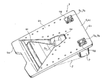
- FIG. 1 is a perspective view showing a bracket according to an embodiment of the present invention as viewed from above.
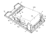
- FIG. 2 is a perspective view of the bracket as seen from above, showing a combination of an on-vehicle camera and an on-vehicle camera by an imaginary line.
- FIG. 3 is a perspective view of the bracket as seen from below, showing a combination of the on-vehicle camera and an on-vehicle camera by imaginary lines.
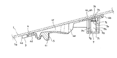
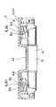
- FIG. 4 is a sectional view taken along the line AA in FIG. 7 showing a state where the bracket is fixed to the window glass.
- FIG. 5 is a cross-sectional view taken along the line AA in FIG.
- FIG. 7 showing a state where the bracket is fixed to a window glass, and an in-vehicle camera combined with an in-vehicle camera is shown by an imaginary line.
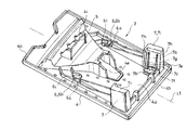
- FIG. 6 is a perspective view showing the bracket as seen from below.
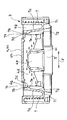
- FIG. 7 is a bottom view of the bracket.
- FIG. 8 is a sectional view taken along the line BB in FIG.
- FIG. 9 is a sectional view taken along the line CC in FIG.
- the bracket 3 is for attaching the vehicle-mounted camera 2 that images the outside of the vehicle through the window glass of the vehicle to the window glass.
- the bracket 3 is used to attach the vehicle-mounted camera 2 that images the outside of the vehicle through the front window 1 of the automobile to the front window 1.
- the concept of the vehicle-mounted camera 2 in this specification includes not only cameras in a narrow sense but also known devices such as sensors that receive optical information.
- reference numeral 1 is a front window
- reference numeral 3 is a bracket
- reference numeral 2 is an in-vehicle camera.
- the front-rear direction of the vehicle is indicated by reference numeral x in FIGS. 1 and 5
- the front side of the vehicle is indicated by reference numeral xa in FIGS. 1 and 5
- the rear side of the vehicle is indicated by reference numeral xb in FIGS. 1 and 5.
- the lateral direction of the vehicle is indicated by the symbol y in FIGS. 1 and 8.
- the front window 1 is provided with an inclination with the front side xa of the vehicle being inclined downward.
- the bracket 3 is fixed to the surface 1a on the vehicle interior side of the front window 1.
- the in-vehicle camera 2 is slid relative to the bracket 3 from the rear side xb of the vehicle toward the front side xa of the vehicle to a predetermined position. After the operation, the rear end portion 2d side of the vehicle-mounted camera 2 is moved upward to a predetermined position, so that the vehicle-mounted camera 2 is fitted into the bracket 3.
- the vehicle-mounted camera 2 is attached to the front window 1 via the bracket 3 so that the light entering portion 2a for image pickup faces the front side xa of the vehicle.
- the camera body 2b has a step 2e facing the front side xa of the vehicle between the front end 2c and the rear end 2d, and the step 2e is provided with the light incident portion 2a. There is.
- the camera body 2b has a smaller vertical dimension z (see FIGS. 1 and 5) between the front end 2c and the step 2e, and a smaller vertical dimension z between the step 2e and the rear end 2d. Making it big.
- the bracket 3 includes a base portion 4 fixed to a surface 1a on the vehicle interior side of the front window 1 serving as the window glass, A pad 5 for the front end 2c of the vehicle-mounted camera 2, A first support portion 6 that is behind the contact portion 5, that is, on the rear side xb of the vehicle in the illustrated example, that receives the first supported portion 2g provided in the vehicle-mounted camera 2 from the rear, A second support part 7 is provided on the rear side of the first support part 6, that is, on the rear side xb of the vehicle in the illustrated example, on the left and right sides, respectively, and receives the rear end part 2d side of the vehicle-mounted camera 2 therebetween. (See Figure 3).
- the bracket 3 uses the first supported portion 2g as a fulcrum from the state where the first supported portion 6 receives the first supported portion 2g on each of the left and right second supported portions 7.
- the upward movement operation of the vehicle-mounted camera 2 on the rear end portion 2d side is permitted by elastic deformation, and the vehicle-mounted camera 2 is elastically returned at the end position of the movement operation and the second supported portion 2j provided on the vehicle-mounted camera 2 is supported. Is provided with an elastic holding piece 7a.
- the left and right second supporting portions 7 are respectively provided with the elastic holding pieces 7a, the first supported portion 2g from the state in which the first supported portion 2g is received.
- the vehicle-mounted camera 2 can be held by the bracket 3 in such a manner that rattling in the vertical direction is reduced as much as possible by an upward movement operation of the vehicle-mounted camera 2 on the side of the rear end 2d with the support portion 2g as a fulcrum.
- the vehicle-mounted camera 2 can be held by the bracket 3 in such a manner that rattling in the left-right direction is reduced as much as possible.
- the bracket 3 is a synthetic resin injection-molded product in which the base portion 4, the contact portion 5, the first support portion 6, and the second support portion 7 are integrally provided.
- the elastic engagement piece 7 a is composed of a part of the second support portion 7. As a result, the bracket 3 is made into one piece, and the elastic holding piece 7a can be reasonably provided with a desired elastic deformation characteristic.
- the base 4 has a plate-like appearance with a substantially quadrangular outline in a plan view (see FIG. 7).
- the vehicle-mounted camera 2 is fitted in a space surrounded by the contact portion 5, the left and right first support portions 6 and the left and right second support portions 7 on the lower surface 4d side of the base portion 4 so as to be fitted therein.
- An opening portion 4e is formed between the front end 4a and the rear end 4b of the base portion 4 to receive the light incident portion 2a of the vehicle-mounted camera 2 from the rear side xb of the vehicle in accordance with the sliding movement operation of the vehicle-mounted camera 2. Has been done.
- a light guide groove 4f formed so as to gradually narrow the groove width in the left-right direction z at a position between the front end 4a and the open portion 4e as it approaches the open portion 4e. Are formed (see FIG. 1).
- the bracket 3 is attached to the front window 1 by adhesion using the attachment surface 4h.
- the mounting surface 4h is adapted to be attached so as to be in close contact with the surface 1a on the vehicle interior side of the front window 1, and has an inclination that follows the inclination of the front window 1.
- the contact portion 5 is provided in the middle of the left-right direction z between the front end 4a and the open portion 4e of the base portion 4 (see FIG. 6).
- the contact portion 5 is configured by a surface of the protrusion 4i protruding vertically from the lower surface 4d of the base portion 4 facing the rear side xb of the vehicle.
- the protrusion 4i has a length along the left-right direction y of the vehicle.
- the first support portion 6 is a virtual center line L1 along the front-rear direction that passes through the middle position of the bracket 3 in the left-right direction y between the contact portion 5 and the open portion 4e of the base portion 4 (see FIG. 6). ) Is provided on the left and right respectively.
- Each of the left and right first support portions 6 includes a base portion 6a that vertically projects from the lower surface 4d of the base portion 4, and a hook portion 6b that horizontally projects from the lower end of the base portion 6a toward the centerline L1.
- the base portion 6a has a rib shape formed so as to be substantially parallel to the center line L1.
- the hanging portion 6b has a fin-like shape protruding laterally from the lower end of the base portion 6a.
- the first support portion 6 further includes a closing portion 6c that closes a space formed by the base portion 6a, the hanging portion 6b, and the lower surface 4d of the base portion 4 on the front side xa of the vehicle.
- the first supported portion 2g of the vehicle-mounted camera 2 is a virtual central axis along the front-rear direction that passes through the middle position of the vehicle-mounted camera 2 in the left-right direction y between the front end 2c of the vehicle-mounted camera 2 and the step 2e. It is provided on each of the left and right sides of L2 (see FIG. 1).
- the first supported portion 2g includes a base portion 2h protruding from the upper surface of the vehicle-mounted camera 2 and a hooked portion 2i protruding from the upper end of the base portion 2h to the side opposite to the central axis L2 side.
- the distance between the protruding ends of the hooked portions 2i in the left and right first supported portions 2g of the vehicle-mounted camera 2 is substantially the same as the distance between the base portions 6a in the left and right first supported portions 6 of the bracket 3. It is becoming equal.
- the second support portions 7 are provided on the left and right sides of the center line L1 between the open portion 4e and the rear end 4b of the base portion 4 (see FIG. 6). Each of the left and right second support portions 7 is formed so as to protrude downward from the lower surface of the base portion 4. More specifically, the second support portion 7 has a hollow rectangular tube shape with a closed lower end.
- the inner side surface 7g of the second support portion 7 facing the center line L1 is inclined in a direction in which the dimension of the second support portion 7 in the left-right direction y is gradually increased toward the upper side. That is, the distance between the left and right second support portions 7 is wide downward and gradually decreases upward (see FIG. 8 ).
- the elastic engagement piece 7a is configured by a part of the inner side surface 7g of the second support portion 7 (see FIG. 6).
- the second support portion 7 has its upper end opened, and the opened upper end communicates with the window hole 4g (see FIG. 8).
- the second support portion 7 can be formed by injection molding through the window hole 4g.
- two split grooves 7h extending from the lower end of the second support portion 7 to the upper end of the second support portion 7 are formed at intervals in the front-rear direction x.
- the space between the two split grooves 7h functions as the elastic engagement piece 7a.
- the two split grooves 7h have their upper ends opened, and the elastic engagement pieces 7a have their upper ends as free ends 7b.
- the elastic holding piece 7a restricts the downward movement of the second supported portion 2j and the second supported portion 2j above the engaging portion 7c. And a free end portion 7b that is pressed against the vehicle body 2 to restrict the movement of the vehicle-mounted camera 2 in the left-right direction y (see FIG. 6).
- the engaging portion 7c is configured by a protruding portion that protrudes toward the center line L1 side below the free end portion 7b of the elastic engaging piece 7a.
- the engaging portion 7c is an inclined surface 7e that gradually lowers the distance from the center line L1 toward the apex portion 7d below the apex portion 7d, and includes an engaging surface 7f that faces upward on the apex portion 7d. ..
- the second supported portion 2j of the vehicle-mounted camera 2 is formed on the left and right sides behind the step 2e of the vehicle-mounted camera 2 at the corners where the upper surface of the vehicle-mounted camera 2 and the rear surface forming a part of the rear end 2d are in contact with each other. It is configured by a plate-shaped portion 2f that is long in the direction y (see FIG. 1).
- the plate-like portion 2f has the plate surfaces arranged laterally, and the dimension in the left-right direction y is between the elastic engagement pieces 7a of the left and right second support portions 7 on the lower end 7i side of the left and right second support portions 7.
- the left and right end portions of the plate-shaped portion 2f function as the second supported portion 2j of the vehicle-mounted camera 2.
- the second supported portion 2j of the in-vehicle camera 2 is positioned below the engaging portions 7c of the left and right second supporting portions 7 of the bracket 3. While abutting the front end portion of the vehicle-mounted camera 2 against the contact portion 5, the first supported portion 2g corresponding to between the hanging portions 6b of the first support portions 6 on the left and right of the bracket 3 and the lower surface 4d of the base portion 4 The vehicle-mounted camera 2 can be slid and operated so that the hooked portion 2i of the vehicle can be inserted.
- the second supported portion 2j causes the elastic support of the second supported portion 7 to move.
- the elastic engagement piece 7a is elastically deformed in contact with the engagement portion 7c of the coupling piece 7a, and the second supported portion 2j is located above the rear end portion 2d of the vehicle-mounted camera 2 up to a position where the second support portion 2j gets over the engagement portion 7c.
- the operation to move to is allowed.
- the elastic deformation of the elastic engagement piece 7a is made smooth because the second supported portion 2j is brought into sliding contact with the inclined surface 7e of the engagement portion 7c.
- the left and right elastic engaging pieces 7a are elastically returned in a direction to reduce the distance between them, and the engagement portion 7c is engaged with the second supported portion 2j.
- the mating surface 7f is caught from below.
- the distance between the free ends 7b of the left and right elastic engagement pieces 7a is smaller than the distance between the left and right second supported portions 2j when the elastic engagement pieces 7a are not elastically deformed. Therefore, when the second supported portion 2j is positioned on the engaging portion 7c of the second supporting portion 7, the elastic engaging piece 7a is elastically deformed and its free end portion 7b is second supported. Press on the part 2j.
- the rear end portion 2d side of the vehicle-mounted camera 2 is sandwiched by the left and right second support portions 7 via the second supported portion 2j.
- the vehicle-mounted camera 2 is held by the bracket 3 in a state where rattling in the left-right direction y is suppressed as much as possible.
- the present invention is not limited to the embodiments described above, but includes all embodiments that can achieve the object of the present invention.
Landscapes
- Engineering & Computer Science (AREA)
- Mechanical Engineering (AREA)
- Fittings On The Vehicle Exterior For Carrying Loads, And Devices For Holding Or Mounting Articles (AREA)
Abstract
Description
窓ガラス越しに車外を撮像する車載カメラを前記窓ガラスに取り付けるためのブラケットであって、
前記窓ガラスの車内側の面に固定されるベース部と、
前記車載カメラの前端部に対する当て部と、
前記当て部よりも後方側にあって、前記車載カメラに備えられた被第一支持部を後方から受け入れる第一支持部と、
前記第一支持部よりも後方側において左右にそれぞれ備えられて間に前記車載カメラの後端部側を受け入れる第二支持部とを備え、
左右の前記第二支持部にそれぞれ、前記第一支持部に前記被第一支持部を受け入れさせた状態からの前記被第一支持部を支点とした前記車載カメラの前記後端部側の上方への移動操作を弾性変形により許容すると共に、前記移動操作の終了位置において弾性復帰して前記車載カメラに備えられた被第二支持部に係合する弾性保持片を備えさせてなる、ものとした。
前記車載カメラ2の前端部2cに対する当て部5と、
前記当て部5よりも後方側、図示の例では、車両の後方側xbにあって、前記車載カメラ2に備えられた被第一支持部2gを後方から受け入れる第一支持部6と、
前記第一支持部6よりも後方側、図示の例では車両の後方側xbにおいて左右にそれぞれ備えられて間に前記車載カメラ2の後端部2d側を受け入れる第二支持部7とを備えている(図3参照)。
2c 前端部
2d 後端部
2g 被第一支持部
2j 被第二支持部
5 当て部
6 第一支持部
7 第二支持部
なお、2019年2月8日に出願された日本特許出願第2019-021177号の明細書、特許請求の範囲、図面及び要約書の全内容をここに引用し、本発明の明細書の開示として、取り入れるものである。
Claims (3)
- 窓ガラス越しに車外を撮像する車載カメラを前記窓ガラスに取り付けるためのブラケットであって、
前記窓ガラスの車内側の面に固定されるベース部と、
前記車載カメラの前端部に対する当て部と、
前記当て部よりも後方側にあって、前記車載カメラに備えられた被第一支持部を後方から受け入れる第一支持部と、
前記第一支持部よりも後方側において左右にそれぞれ備えられて間に前記車載カメラの後端部側を受け入れる第二支持部とを備え、
左右の前記第二支持部にそれぞれ、前記第一支持部に前記被第一支持部を受け入れさせた状態からの前記被第一支持部を支点とした前記車載カメラの前記後端部側の上方への移動操作を弾性変形により許容すると共に、前記移動操作の終了位置において弾性復帰して前記車載カメラに備えられた被第二支持部に係合する弾性保持片を備えさせてなる、車載カメラ用ブラケット。 - 前記弾性保持片は、前記係合状態において、前記被第二支持部の下方への移動を規制する係合部と、前記係合部よりも上方において前記被第二支持部に押しつけられて前記車載カメラの左右方向の移動を規制する自由端部とを備えてなる、請求項1に記載の車載カメラ用ブラケット。
- 前記ベース部に前記当て部、第一支持部、及び前記第二支持部を一体に備えた合成樹脂の射出成形品としてなる、請求項1又は請求項2に記載の車載カメラ用ブラケット。
Priority Applications (4)
| Application Number | Priority Date | Filing Date | Title |
|---|---|---|---|
| US17/416,729 US11890995B2 (en) | 2019-02-08 | 2020-01-27 | Bracket for vehicle mount camera |
| GB2109908.0A GB2594845B (en) | 2019-02-08 | 2020-01-27 | Bracket for vehicle mount camera |
| DE112020000214.4T DE112020000214B4 (de) | 2019-02-08 | 2020-01-27 | Halterung für eine fahrzeugmontierte Kamera |
| CN202080008995.XA CN113316530A (zh) | 2019-02-08 | 2020-01-27 | 车载摄像装置用支架 |
Applications Claiming Priority (2)
| Application Number | Priority Date | Filing Date | Title |
|---|---|---|---|
| JP2019-021177 | 2019-02-08 | ||
| JP2019021177A JP7002485B2 (ja) | 2019-02-08 | 2019-02-08 | 車載カメラ用ブラケット |
Publications (1)
| Publication Number | Publication Date |
|---|---|
| WO2020162244A1 true WO2020162244A1 (ja) | 2020-08-13 |
Family
ID=71948246
Family Applications (1)
| Application Number | Title | Priority Date | Filing Date |
|---|---|---|---|
| PCT/JP2020/002687 Ceased WO2020162244A1 (ja) | 2019-02-08 | 2020-01-27 | 車載カメラ用ブラケット |
Country Status (6)
| Country | Link |
|---|---|
| US (1) | US11890995B2 (ja) |
| JP (1) | JP7002485B2 (ja) |
| CN (1) | CN113316530A (ja) |
| DE (1) | DE112020000214B4 (ja) |
| GB (1) | GB2594845B (ja) |
| WO (1) | WO2020162244A1 (ja) |
Families Citing this family (9)
| Publication number | Priority date | Publication date | Assignee | Title |
|---|---|---|---|---|
| JP7413919B2 (ja) * | 2020-05-21 | 2024-01-16 | 株式会社デンソー | 車載装置 |
| US11951911B2 (en) * | 2021-09-13 | 2024-04-09 | Avery Oneil Patrick | Mounting system, apparatus, and method for securing one or more devices to a vehicle window |
| FR3129640A1 (fr) * | 2021-11-26 | 2023-06-02 | Psa Automobiles Sa | Support destiné à la fixation d'un module télématique à un élément de structure interne d'un véhicule automobile, système télématique et véhicule comprenant un tel support |
| JP7630454B2 (ja) * | 2022-01-17 | 2025-02-17 | 株式会社ニフコ | 車載機器用ブラケット |
| EP4269175A1 (en) * | 2022-04-28 | 2023-11-01 | Veoneer Sweden AB | A mounting bracket and a vehicle camera arrangement |
| JP7707218B2 (ja) * | 2023-01-23 | 2025-07-14 | 株式会社ニフコ | 保持構造 |
| US20250060174A1 (en) * | 2023-08-15 | 2025-02-20 | Valeo Systemes Thermiques | Clip fastener |
| WO2025118051A1 (en) * | 2023-12-05 | 2025-06-12 | Fca Fiat Chrysler Automoveis Brasil Ltda | Plastic support for attaching a vehicle camera |
| CN221757452U (zh) * | 2024-01-29 | 2024-09-24 | 大众酷翼(北京)科技有限公司 | 摄像头安装装置及车辆 |
Citations (3)
| Publication number | Priority date | Publication date | Assignee | Title |
|---|---|---|---|---|
| US20160216595A1 (en) * | 2015-01-28 | 2016-07-28 | Trw Automotive U.S. Llc | Camera bracket |
| JP2016190616A (ja) * | 2015-03-31 | 2016-11-10 | トヨタ自動車株式会社 | 車両前方情報取得装置 |
| US20180239223A1 (en) * | 2017-02-22 | 2018-08-23 | Trw Automotive Us Llc | Moderation of a driver assist camera enhancement via a vehicle windshield |
Family Cites Families (14)
| Publication number | Priority date | Publication date | Assignee | Title |
|---|---|---|---|---|
| US8339453B2 (en) * | 2010-07-14 | 2012-12-25 | Trw Automotive U.S. Llc | Apparatus for use in association with a vehicle |
| US9596387B2 (en) * | 2011-08-02 | 2017-03-14 | Magna Electronics Inc. | Vehicular camera system |
| JP5947759B2 (ja) * | 2013-07-23 | 2016-07-06 | 本田技研工業株式会社 | カメラユニット |
| KR20150066770A (ko) * | 2013-12-09 | 2015-06-17 | 엘지이노텍 주식회사 | 후방 카메라가 장착된 자동차 |
| US9783128B2 (en) * | 2014-12-15 | 2017-10-10 | Trw Automotive U.S. Llc | Vehicle camera defogging vent with glare mitigation |
| JP6197812B2 (ja) * | 2015-03-05 | 2017-09-20 | トヨタ自動車株式会社 | 車載用カメラの取付構造 |
| EP3268249B1 (en) * | 2015-03-12 | 2022-09-14 | ZF Active Safety and Electronics US LLC | Mounting arrangement for a driver assist system housing |
| JP6392267B2 (ja) | 2016-03-24 | 2018-09-19 | 本田技研工業株式会社 | センサブラケット |
| JP6307545B2 (ja) * | 2016-03-24 | 2018-04-04 | 本田技研工業株式会社 | センサブラケット |
| US11150448B2 (en) * | 2016-11-06 | 2021-10-19 | Denso Corporation | Vehicle windshield mounted camera module |
| EP3330131B1 (en) * | 2016-12-05 | 2019-11-13 | Continental Automotive GmbH | Bracket device, system comprising a bracket device and a sensor unit, and a vehicle |
| JP6387558B1 (ja) | 2017-07-20 | 2018-09-12 | 株式会社マーケテック | 貸与品所在管理システム及び貸与品所在管理方法 |
| JP7163608B2 (ja) * | 2018-04-13 | 2022-11-01 | 株式会社デンソー | 車両用部品の取付け構造、車両用部品の取付け方法および車両用のウインドシールド |
| JP6910384B2 (ja) * | 2019-01-29 | 2021-07-28 | 株式会社ニフコ | 車載カメラ用ブラケット |
-
2019
- 2019-02-08 JP JP2019021177A patent/JP7002485B2/ja active Active
-
2020
- 2020-01-27 CN CN202080008995.XA patent/CN113316530A/zh active Pending
- 2020-01-27 DE DE112020000214.4T patent/DE112020000214B4/de active Active
- 2020-01-27 US US17/416,729 patent/US11890995B2/en active Active
- 2020-01-27 GB GB2109908.0A patent/GB2594845B/en active Active
- 2020-01-27 WO PCT/JP2020/002687 patent/WO2020162244A1/ja not_active Ceased
Patent Citations (3)
| Publication number | Priority date | Publication date | Assignee | Title |
|---|---|---|---|---|
| US20160216595A1 (en) * | 2015-01-28 | 2016-07-28 | Trw Automotive U.S. Llc | Camera bracket |
| JP2016190616A (ja) * | 2015-03-31 | 2016-11-10 | トヨタ自動車株式会社 | 車両前方情報取得装置 |
| US20180239223A1 (en) * | 2017-02-22 | 2018-08-23 | Trw Automotive Us Llc | Moderation of a driver assist camera enhancement via a vehicle windshield |
Also Published As
| Publication number | Publication date |
|---|---|
| GB202109908D0 (en) | 2021-08-25 |
| JP7002485B2 (ja) | 2022-02-10 |
| US20220041117A1 (en) | 2022-02-10 |
| GB2594845A (en) | 2021-11-10 |
| JP2020128136A (ja) | 2020-08-27 |
| CN113316530A (zh) | 2021-08-27 |
| DE112020000214T5 (de) | 2021-08-19 |
| DE112020000214B4 (de) | 2025-02-13 |
| US11890995B2 (en) | 2024-02-06 |
| GB2594845B (en) | 2022-11-30 |
Similar Documents
| Publication | Publication Date | Title |
|---|---|---|
| WO2020162244A1 (ja) | 車載カメラ用ブラケット | |
| WO2020158449A1 (ja) | 車載カメラ用ブラケット | |
| JP7147613B2 (ja) | カメラ搭載構造 | |
| CN110371042B (zh) | 用于车辆部件的附接单元和附接方法以及用于车辆的风挡 | |
| CN109328153B (zh) | 摄像头单元 | |
| JP5672539B2 (ja) | 車両用カメラユニットおよびブラケット | |
| US20210323483A1 (en) | Bracket for vehicle mount device | |
| KR20210035809A (ko) | 차량 탑재 카메라의 보유 지지 방법, 차량 탑재 카메라, 브래킷 | |
| US20070115434A1 (en) | External ornament for vehicle and vehicle including external ornament | |
| CN102741610B (zh) | 卡夹 | |
| JP6767186B2 (ja) | 車載用カメラ装置 | |
| JPWO2018190116A1 (ja) | 撮像装置 | |
| JP7630454B2 (ja) | 車載機器用ブラケット | |
| JP7802296B2 (ja) | 車載機器取付構造 | |
| JP4197624B2 (ja) | 車両周辺視認装置 | |
| JP7733621B2 (ja) | 車載機器用ブラケット | |
| US20260054659A1 (en) | Component cover mounting assembly | |
| JP2533080Y2 (ja) | 気泡管用反射鏡装置 | |
| JP4017449B2 (ja) | 車両用サンバイザ | |
| WO2025088742A1 (ja) | カメラ取付構造およびブラケット | |
| JP2009036234A (ja) | クリップ装着構造 | |
| JP2005041270A (ja) | 車両用視認装置 |
Legal Events
| Date | Code | Title | Description |
|---|---|---|---|
| 121 | Ep: the epo has been informed by wipo that ep was designated in this application |
Ref document number: 20752618 Country of ref document: EP Kind code of ref document: A1 |
|
| ENP | Entry into the national phase |
Ref document number: 202109908 Country of ref document: GB Kind code of ref document: A Free format text: PCT FILING DATE = 20200127 |
|
| WWE | Wipo information: entry into national phase |
Ref document number: 2109908.0 Country of ref document: GB |
|
| 122 | Ep: pct application non-entry in european phase |
Ref document number: 20752618 Country of ref document: EP Kind code of ref document: A1 |
|
| WWG | Wipo information: grant in national office |
Ref document number: 2109908.0 Country of ref document: GB |
|
| WWG | Wipo information: grant in national office |
Ref document number: 112020000214 Country of ref document: DE |