WO2020153417A1 - 車輪用軸受装置の製造方法および車輪用軸受装置 - Google Patents
車輪用軸受装置の製造方法および車輪用軸受装置 Download PDFInfo
- Publication number
- WO2020153417A1 WO2020153417A1 PCT/JP2020/002240 JP2020002240W WO2020153417A1 WO 2020153417 A1 WO2020153417 A1 WO 2020153417A1 JP 2020002240 W JP2020002240 W JP 2020002240W WO 2020153417 A1 WO2020153417 A1 WO 2020153417A1
- Authority
- WO
- WIPO (PCT)
- Prior art keywords
- bearing device
- wheel
- pressure
- wheel bearing
- atmosphere
- Prior art date
- Legal status (The legal status is an assumption and is not a legal conclusion. Google has not performed a legal analysis and makes no representation as to the accuracy of the status listed.)
- Ceased
Links
Images


Classifications
-
- F—MECHANICAL ENGINEERING; LIGHTING; HEATING; WEAPONS; BLASTING
- F16—ENGINEERING ELEMENTS AND UNITS; GENERAL MEASURES FOR PRODUCING AND MAINTAINING EFFECTIVE FUNCTIONING OF MACHINES OR INSTALLATIONS; THERMAL INSULATION IN GENERAL
- F16C—SHAFTS; FLEXIBLE SHAFTS; ELEMENTS OR CRANKSHAFT MECHANISMS; ROTARY BODIES OTHER THAN GEARING ELEMENTS; BEARINGS
- F16C43/00—Assembling bearings
- F16C43/04—Assembling rolling-contact bearings
- F16C43/045—Mounting or replacing seals
-
- B—PERFORMING OPERATIONS; TRANSPORTING
- B23—MACHINE TOOLS; METAL-WORKING NOT OTHERWISE PROVIDED FOR
- B23P—METAL-WORKING NOT OTHERWISE PROVIDED FOR; COMBINED OPERATIONS; UNIVERSAL MACHINE TOOLS
- B23P21/00—Machines for assembling a multiplicity of different parts to compose units, with or without preceding or subsequent working of such parts, e.g. with program control
-
- B—PERFORMING OPERATIONS; TRANSPORTING
- B60—VEHICLES IN GENERAL
- B60B—VEHICLE WHEELS; CASTORS; AXLES FOR WHEELS OR CASTORS; INCREASING WHEEL ADHESION
- B60B27/00—Hubs
- B60B27/0073—Hubs characterised by sealing means
-
- B—PERFORMING OPERATIONS; TRANSPORTING
- B60—VEHICLES IN GENERAL
- B60B—VEHICLE WHEELS; CASTORS; AXLES FOR WHEELS OR CASTORS; INCREASING WHEEL ADHESION
- B60B27/00—Hubs
- B60B27/0094—Hubs one or more of the bearing races are formed by the hub
-
- F—MECHANICAL ENGINEERING; LIGHTING; HEATING; WEAPONS; BLASTING
- F16—ENGINEERING ELEMENTS AND UNITS; GENERAL MEASURES FOR PRODUCING AND MAINTAINING EFFECTIVE FUNCTIONING OF MACHINES OR INSTALLATIONS; THERMAL INSULATION IN GENERAL
- F16C—SHAFTS; FLEXIBLE SHAFTS; ELEMENTS OR CRANKSHAFT MECHANISMS; ROTARY BODIES OTHER THAN GEARING ELEMENTS; BEARINGS
- F16C19/00—Bearings with rolling contact, for exclusively rotary movement
- F16C19/02—Bearings with rolling contact, for exclusively rotary movement with bearing balls essentially of the same size in one or more circular rows
- F16C19/14—Bearings with rolling contact, for exclusively rotary movement with bearing balls essentially of the same size in one or more circular rows for both radial and axial load
- F16C19/18—Bearings with rolling contact, for exclusively rotary movement with bearing balls essentially of the same size in one or more circular rows for both radial and axial load with two or more rows of balls
- F16C19/181—Bearings with rolling contact, for exclusively rotary movement with bearing balls essentially of the same size in one or more circular rows for both radial and axial load with two or more rows of balls with angular contact
- F16C19/183—Bearings with rolling contact, for exclusively rotary movement with bearing balls essentially of the same size in one or more circular rows for both radial and axial load with two or more rows of balls with angular contact with two rows at opposite angles
- F16C19/184—Bearings with rolling contact, for exclusively rotary movement with bearing balls essentially of the same size in one or more circular rows for both radial and axial load with two or more rows of balls with angular contact with two rows at opposite angles in O-arrangement
- F16C19/186—Bearings with rolling contact, for exclusively rotary movement with bearing balls essentially of the same size in one or more circular rows for both radial and axial load with two or more rows of balls with angular contact with two rows at opposite angles in O-arrangement with three raceways provided integrally on parts other than race rings, e.g. third generation hubs
-
- F—MECHANICAL ENGINEERING; LIGHTING; HEATING; WEAPONS; BLASTING
- F16—ENGINEERING ELEMENTS AND UNITS; GENERAL MEASURES FOR PRODUCING AND MAINTAINING EFFECTIVE FUNCTIONING OF MACHINES OR INSTALLATIONS; THERMAL INSULATION IN GENERAL
- F16C—SHAFTS; FLEXIBLE SHAFTS; ELEMENTS OR CRANKSHAFT MECHANISMS; ROTARY BODIES OTHER THAN GEARING ELEMENTS; BEARINGS
- F16C33/00—Parts of bearings; Special methods for making bearings or parts thereof
- F16C33/72—Sealings
- F16C33/76—Sealings of ball or roller bearings
- F16C33/78—Sealings of ball or roller bearings with a diaphragm, disc, or ring, with or without resilient members
- F16C33/784—Sealings of ball or roller bearings with a diaphragm, disc, or ring, with or without resilient members mounted to a groove in the inner surface of the outer race and extending toward the inner race
- F16C33/7843—Sealings of ball or roller bearings with a diaphragm, disc, or ring, with or without resilient members mounted to a groove in the inner surface of the outer race and extending toward the inner race with a single annular sealing disc
- F16C33/7853—Sealings of ball or roller bearings with a diaphragm, disc, or ring, with or without resilient members mounted to a groove in the inner surface of the outer race and extending toward the inner race with a single annular sealing disc with one or more sealing lips to contact the inner race
-
- F—MECHANICAL ENGINEERING; LIGHTING; HEATING; WEAPONS; BLASTING
- F16—ENGINEERING ELEMENTS AND UNITS; GENERAL MEASURES FOR PRODUCING AND MAINTAINING EFFECTIVE FUNCTIONING OF MACHINES OR INSTALLATIONS; THERMAL INSULATION IN GENERAL
- F16J—PISTONS; CYLINDERS; SEALINGS
- F16J15/00—Sealings
-
- B—PERFORMING OPERATIONS; TRANSPORTING
- B60—VEHICLES IN GENERAL
- B60B—VEHICLE WHEELS; CASTORS; AXLES FOR WHEELS OR CASTORS; INCREASING WHEEL ADHESION
- B60B2320/00—Manufacturing or maintenance operations
- B60B2320/10—Assembling; disassembling
-
- F—MECHANICAL ENGINEERING; LIGHTING; HEATING; WEAPONS; BLASTING
- F16—ENGINEERING ELEMENTS AND UNITS; GENERAL MEASURES FOR PRODUCING AND MAINTAINING EFFECTIVE FUNCTIONING OF MACHINES OR INSTALLATIONS; THERMAL INSULATION IN GENERAL
- F16C—SHAFTS; FLEXIBLE SHAFTS; ELEMENTS OR CRANKSHAFT MECHANISMS; ROTARY BODIES OTHER THAN GEARING ELEMENTS; BEARINGS
- F16C2326/00—Articles relating to transporting
- F16C2326/01—Parts of vehicles in general
- F16C2326/02—Wheel hubs or castors
-
- F—MECHANICAL ENGINEERING; LIGHTING; HEATING; WEAPONS; BLASTING
- F16—ENGINEERING ELEMENTS AND UNITS; GENERAL MEASURES FOR PRODUCING AND MAINTAINING EFFECTIVE FUNCTIONING OF MACHINES OR INSTALLATIONS; THERMAL INSULATION IN GENERAL
- F16C—SHAFTS; FLEXIBLE SHAFTS; ELEMENTS OR CRANKSHAFT MECHANISMS; ROTARY BODIES OTHER THAN GEARING ELEMENTS; BEARINGS
- F16C33/00—Parts of bearings; Special methods for making bearings or parts thereof
- F16C33/72—Sealings
- F16C33/723—Shaft end sealing means, e.g. cup-shaped caps or covers
Definitions
- the present invention relates to a method for manufacturing a wheel bearing device and a wheel bearing device.
- a wheel bearing device that rotatably supports a wheel in a suspension device such as an automobile has been known.
- a hub wheel which is an inner member connected to a wheel, is rotatably supported by an outer member via rolling elements.
- the bearing device for a wheel is improved in sealing performance by providing a seal member or the like in the gap between the outer member and the inner member in order to prevent foreign matter such as muddy water and dust from entering the outer member and the inner member. I am making it.
- the atmospheric pressure inside the bearing changes due to changes in the atmospheric pressure outside.
- the atmospheric pressure outside is larger than the atmospheric pressure (pressure) inside the bearing.
- the atmospheric pressure outside is smaller than the atmospheric pressure inside the bearing. Therefore, in the bearing device for a wheel, when the internal pressure of the bearing becomes negative with respect to the atmospheric pressure due to the atmospheric pressure difference between the bearing assembly site and the site of use, the seal lip of the seal member is attracted to the sliding surface and the rotational torque is reduced. Increase.
- a piston is axially slidably provided on the inner peripheral surface of the hub wheel. Then, when the pressure inside the bearing changes due to the temperature change, the volume of the space inside the bearing changes due to the axial displacement of the piston.
- the structure is complicated because the slidable piston is provided in the hub wheel for pressure adjustment inside the bearing.
- muddy water may enter the inside of the bearing from the sliding portion of the piston.
- An object of the present invention is to provide a wheel bearing device manufacturing method and a wheel bearing device manufacturing method.
- an outer member having a double row outer raceway surface formed on the inner periphery thereof and a double row inner raceway surface facing the outer row raceway surface of the double row are formed.
- the atmosphere in the working chamber is replaced with an atmosphere having a predetermined configuration, and then the pressure is adjusted.
- the pressure in the working chamber is adjusted after the atmosphere having a predetermined humidity or the atmosphere having a predetermined nitrogen concentration is replaced. is there.
- a front chamber that regulates the internal air pressure and communicates with the working chamber is used, and the outer sealing member and the inner sealing member are used.
- the sealing members the wheel bearing device in which any one of them is fitted is enclosed in the front chamber, and the wheel bearing device is placed in the working chamber after adjusting the pressure in the front chamber to the predetermined atmospheric pressure.
- a rear chamber that regulates the internal air pressure and communicates with the working chamber is used, and after adjusting the inside pressure of the rear chamber to the predetermined atmospheric pressure, the inside of the working chamber is adjusted.
- the atmosphere of the front chamber and the rear chamber is replaced with an atmosphere having the same composition as the working chamber.
- the pressure is adjusted later.
- the air pressure inside the wheel bearing device is regulated to a predetermined air pressure according to the environment in the area where the wheel bearing device is used. is there.
- At least one of the management information regarding the atmospheric pressure inside the wheel bearing device and the composition of the atmosphere inside the wheel bearing device is the outer member or the inner member. It is described in.
- the inner side opening of the bearing device for a wheel is sealed by the sealing member in the working chamber where the pressure is adjusted to the pressure based on the environment of the use area.
- the atmospheric pressure is set to a predetermined atmospheric pressure based on the environment of the use area.
- the inner side opening of the bearing device for a wheel is sealed by the sealing member in the working chamber in which the atmosphere is replaced with the atmosphere having the predetermined composition and state.
- An atmosphere having a predetermined composition and state is filled.
- the wheel bearing device is moved from the pressure-controlled front chamber to the pressure-controlled working chamber, and the pressure-controlled work chamber is moved to the pressure-controlled rear chamber.
- the pressure and composition of the atmosphere in the working chamber do not change when the wheel bearing device is loaded and unloaded.
- it becomes easy to manage the atmospheric pressure and the atmospheric condition inside the bearing of the wheel bearing device and it is possible to keep the pressure difference between the atmospheric pressure inside the bearing and the atmospheric pressure in the region of use within an allowable range.
- the air pressure inside the bearing is sealed by the sealing member so as to maintain a predetermined atmospheric pressure based on the environment of the usage area.
- the pressure difference between the atmospheric pressure inside the bearing and the atmospheric pressure in the region of use can be kept within an allowable range without providing a mechanism for adjusting pressure on the wheel bearing device.
- the composition and state of the atmosphere inside the bearing can be easily confirmed from the outside of the bearing, so that the bearing device for a wheel adjusted to the inside atmosphere according to the use environment can be reliably selected. can do.
- it becomes easy to manage the atmospheric pressure and the atmospheric state inside the bearing of the wheel bearing device and it is possible to maintain the pressure difference between the atmospheric pressure inside the bearing and the atmospheric pressure in the region of use within an allowable range.
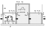
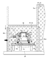
- FIG. 3 is a schematic cross-sectional view showing a state in which the wheel bearing device is sealed in the front chamber of the wheel bearing device manufacturing apparatus.
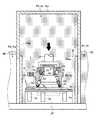
- FIG. 5 is a schematic cross-sectional view showing a state in which the wheel bearing device is moved from the front chamber to the working chamber in the wheel bearing device manufacturing apparatus.
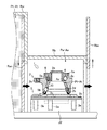
- FIG. 3 is a schematic cross-sectional view showing a state in which a seal member is fitted to the wheel bearing device in the working chamber in the wheel bearing device manufacturing apparatus.
- FIG. 3 is a schematic cross-sectional view showing a state in which a rear chamber that seals the wheel bearing device is opened to the atmosphere in the wheel bearing device manufacturing apparatus.
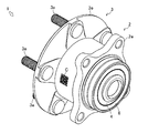
- a wheel bearing device 1 which is a first embodiment of the wheel bearing device according to the present invention will be described below with reference to FIGS. 1 and 2.
- the wheel bearing device 1 rotatably supports the wheels in a suspension device of a vehicle such as an automobile.
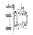
- the wheel bearing device 1 includes an outer ring 2 which is an outer member, a hub wheel 3 which is an inner member, an inner ring 4, two inner row ball rows 5a (see FIG. 2) which are rolling rows, and an outer ball row. 5b (see FIG. 2), an inner seal member 6 (see FIG. 2), and an outer seal member 9 (see FIG. 2).
- the inner side refers to the vehicle body side of the wheel bearing device 1 when attached to the vehicle body
- the outer side refers to the wheel side of the wheel bearing device 1 when attached to the vehicle body.
- the axial direction represents a direction along the rotation axis of the wheel bearing device 1.
- the outer ring 2 is made of medium-high carbon steel containing 0.40 to 0.80 wt% of carbon such as S53C.
- An inner opening 2a into which the inner seal member 6 can be fitted is formed at the inner end of the outer ring 2.
- An outer opening 2b into which the outer seal member 9 can be fitted is formed at the outer end of the outer ring 2.
- an outer raceway surface 2c on the inner side and an outer raceway surface 2d on the outer side are formed in a ring shape.
- a hardened layer having a surface hardness in the range of 58 to 64 HRC is formed by, for example, induction hardening.
- a vehicle body mounting flange 2e for mounting on a member (knuckle) on the vehicle body side (not shown) is integrally formed.
- the hub wheel 3 is made of medium-high carbon steel containing 0.40 to 0.80 wt% of carbon such as S53C. At the inner end of the hub wheel 3, a small-diameter step portion 3a having a diameter smaller than that of the outer end is formed on the outer peripheral surface.
- a wheel mounting flange 3b for mounting a wheel is integrally formed on the outer end of the hub wheel 3.
- the wheel mounting flange 3b is provided with a plurality of hub bolts 3e at circumferentially equidistant positions.
- the hub wheel 3 is provided with an inner raceway surface 3c on the outer side so as to face the outer raceway surface 2d on the outer side of the outer race 2. Further, the hub wheel 3 is provided with a lip sliding surface 3d of the outer seal member 9 on the base side of the wheel mounting flange 3b.
- the hub wheel 3 is provided with an inner ring 4 on the small-diameter step portion 3a.
- the inner ring 4 is a rolling row and applies a preload to the inner ball row 5a arranged on the vehicle body side when mounted on the vehicle and the outer ball row 5b arranged on the wheel side when mounted on the vehicle.
- the inner ring 4 is made of, for example, high carbon chrome bearing steel such as SUJ2, and is subjected to a hardening treatment in the range of 58 to 64 HRC to the core portion by means of quench hardening.
- an annular inner raceway surface 4a is formed in the circumferential direction.
- the inner ring 4 is fixed to the small-diameter step portion 3a of the hub wheel 3 by press fitting and caulking.
- the inner race 4 constitutes the inner raceway surface 4 a on the inner side of the hub wheel 3.
- the inner raceway surface 4a of the inner race 4 at the inner end is opposed to the outer raceway surface 2c of the outer race 2 on the inner side.
- the inner side ball row 5a and the outer side ball row 5b which are rolling rows, have a plurality of balls 5 that are rolling elements and are held in an annular shape by a cage 10.
- the inner ball row 5a and the outer ball row 5b are made of, for example, high carbon chrome bearing steel such as SUJ2, and are hardened to the core portion by zub quenching in the range of 62 to 67 HRC.
- the inner ball row 5a is rotatably sandwiched between the inner raceway surface 4a of the inner ring 4 and the outer raceway surface 2c of the outer ring 2 on the inner side.
- the outer ball row 5b is rotatably sandwiched between the inner raceway surface 3c of the hub wheel 3 and the outer raceway surface 2d of the outer race 2 on the outer side.
- the wheel bearing device 1 includes a double row angular contact ball bearing including an outer ring 2, a hub ring 3 and an inner ring 4, an inner ball row 5a, and an outer ball row 5b.
- the wheel bearing device 1 is configured with a double row angular contact ball bearing, but may be configured with a bearing such as a double row tapered roller bearing.
- the pitch circle diameter of the outer side ball row 5b is larger than the pitch circle diameter of the inner side ball row 5a, but it is not limited to this.
- the inner seal member 6 that is a sealing member is a pack seal that closes the gap between the inner opening 2 a of the outer ring 2 and the inner ring 4.
- the inner seal member 6 is composed of, for example, a two-side lip-type pack seal with an encoder that brings two seal lips into contact with each other.
- the inner seal member 6 includes a substantially cylindrical seal plate 7 and a substantially cylindrical slinger 8.
- the seal plate 7 is composed of a core metal and a seal lip.
- the core metal is made of metal, for example, a ferritic stainless steel plate (JIS standard SUS430 series, etc.), an austenitic stainless steel plate (JIS standard SUS304 series, etc.), or a rust-proof cold rolled steel plate (JIS standard). SPCC system, etc.).
- the cored bar is formed by bending the outer edge portion of an annular steel plate by press working, and is formed into a substantially L shape in a cross-sectional view in the axial direction.
- the seal plate 7 is fitted and fixed to the inner opening 2 a of the outer ring 2.
- a plurality of seal lips are vulcanized and bonded to the inner side surface of the seal plate 7, for example.
- the plurality of seal lips are, for example, NBR (acrylonitrile-butadiene rubber), HNBR (hydrogenated acrylonitrile butadiene rubber) having excellent heat resistance, EPDM (ethylene propylene rubber), ACM (polyene having excellent heat resistance and chemical resistance). It is made of synthetic rubber such as acrylic rubber), FKM (fluorine rubber), or silicone rubber.
- the slinger 8 is made of, for example, a steel plate equivalent to the seal plate 7.
- the slinger 8 is formed in a substantially L-shape in an axial sectional view by bending an outer edge portion and an inner edge portion of an annular steel plate by press working.
- the slinger 8 is fitted and fixed to the inner ring 4 on the inner side of the seal plate 7.
- the slinger 8 is arranged so as to face the seal plate 7 in the axial direction.
- the inner seal member 6 is arranged so that the seal plate 7 fitted in the inner opening 2a of the outer ring 2 and the slinger 8 fitted in the inner ring 4 face each other to form a pack seal. doing.
- the plurality of seal lips of the seal plate 7 come into contact with or come close to the slinger 8 that is a sliding surface through the oil film of grease, prevent the grease inside the wheel bearing device 1 from leaking to the outside, and prevent the bearing for the wheel. It prevents the entry of muddy water and dust from the outside of the device 1.
- the inner seal member 6 prevents leakage of lubricating grease from the inner opening 2a of the outer ring 2 and entry of rainwater or dust from the outside.
- the outer seal member 9 that is a sealing member is a seal member that mainly closes the gap between the outer ring 2 and the hub ring 3.
- the outer-side sealing member 9 includes, for example, a core metal formed of a metal plate equivalent to the sealing plate 7 of the inner-side sealing member 6 in a substantially cylindrical shape, and a plurality of synthetic rubbers such as NBR (acrylonitrile-butadiene rubber).
- the seal lip is vulcanized and bonded.
- the outer seal member 9 has a cylindrical portion fitted in the outer opening 2b of the outer ring 2, and a plurality of seal lips come into contact with or close to the lip sliding surface 3d of the hub ring 3 through an oil film to form a hub ring. 3 is slidable.
- the space between the outer member composed of the outer ring 2 and the inner member composed of the hub wheel 3 and the inner ring 4 (hereinafter simply referred to as “bearing inside”) is the same as the inner seal member 6. It is sealed with the outer seal member 9.
- the bearing device 1 for a wheel is hermetically sealed by fitting the inner side seal member 6, the atmosphere A inside the bearing is replaced with the atmosphere At having a predetermined composition, and the atmospheric pressure P inside the bearing is used in a usage region (used). The pressure is adjusted to a predetermined atmospheric pressure Pt according to the environment of the region).
- the air pressure P inside the bearing is maintained at a predetermined air pressure Pt according to the environment of the use area by being sealed by the inner seal member 6 and the outer seal member 9.
- predetermined atmospheric pressure Pt according to the environment of the use region
- predetermined atmospheric pressure Pt means the atmospheric pressure Pa and the wheel in the region where the wheel bearing device 1 is assembled.
- the pressure difference between the atmospheric pressure P inside the bearing and the atmospheric pressure Pu in the usage region reduces the sealing performance of the inner seal member 6 and the outer seal member 9. Or the atmospheric pressure at which the rotational resistance of the hub wheel 3 (inner wheel 4) does not increase.
- the predetermined atmospheric pressure Pt also takes into consideration the pressure difference due to the volume change of the gas caused by the temperature difference between the temperature of the assembled area and the temperature of the used area. It is desirable that the predetermined pressure Pt be set to be a slight positive pressure with respect to the atmospheric pressure Pu in the usage area.
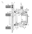
- FIG. 11 a wheel bearing device 11 that is a second embodiment of the wheel bearing device according to the present invention will be described with reference to FIG.
- the wheel bearing device 11 according to each of the following embodiments is used in place of the wheel bearing device 1 in the wheel bearing device 1 shown in FIGS. 1 and 2, and is used in the description thereof.
- the figure numbers and the reference numerals are used to indicate the same things, and in the following embodiments, specific description will be omitted regarding the same points as the embodiments already described, and different points will be mainly described. ..
- the wheel bearing device 11 includes an outer ring 2 which is an outer member, a hub wheel 3 which is an inner member, an inner ring 4, two inner row ball rows 5a (see FIG. 2) which are rolling rows, and an outer ball row. 5b (see FIG. 2), a cover 12, an annular inner seal member 13 provided on the cover 12, and an outer seal member 9 (see FIG. 2).
- the cover 12 which is a sealing member, blocks the inner opening 2a of the outer ring 2 to prevent foreign matter such as muddy water from entering from the outside.
- the cover 12 is formed into a cylindrical shape with a bottom by press working.
- the cover 12 is, for example, a ferritic stainless steel sheet (JIS standard SUS430 series or the like), an austenitic stainless steel sheet (JIS standard SUS304 series or the like), or a rust-proof cold-rolled steel sheet (JIS standard SPCC series or the like). It consists of
- the cover 12 is one in which the fitting portion 12a, the seal support portion 12b, and the bottom portion 12c are integrally connected.
- the fitting portion 12a and the seal support portion 12b are formed on the same axis in the cylindrical portion of the cover 12.
- the fitting portion 12a is formed at the opening-side end of the cover 12.
- the fitting portion 12a has an outer diameter larger than the inner diameter of the inner opening 2a of the outer ring 2.
- the fitting portion 12a has an outer diameter and an axial length that can be press-fitted into the inner opening 2a.
- the fitting portion 12 a is fitted into the inner opening 2 a of the outer ring 2.
- the seal support portion 12b supports the inner seal member 13.
- the seal support portion 12b is arranged adjacent to the inner side of the fitting portion 12a.
- the seal support portion 12b has an outer diameter smaller than that of the fitting portion 12a.
- the seal support portion 12b forms a space in which the inner seal member 13 can be disposed between the seal support portion 12b and the inner peripheral surface of the inner opening 2a.
- a bottom portion 12c is formed on the inner side of the seal support portion 12b. The bottom portion 12c covers the inner opening 2a of the outer ring 2.
- the annular inner seal member 13 closes the gap between the outer ring 2 and the cover 12.
- the inner seal member 13 is fixed to the outer peripheral surface of the seal support portion 12b of the cover 12 by, for example, vulcanization adhesion. That is, the inner seal member 13 is provided so as to be adjacent to the fitting portion 12a.
- the inner seal member 13 is, for example, NBR (acrylonitrile-butadiene rubber), HNBR (hydrogenated acrylonitrile-butadiene rubber) excellent in heat resistance, EPDM (ethylene propylene rubber), ACM (polyene excellent in heat resistance and chemical resistance). It is made of synthetic rubber such as acrylic rubber), FKM (fluorine rubber), or silicone rubber.
- the inner seal member 13 has an outer diameter larger than the inner diameter of the inner opening 2a of the outer ring 2.
- the inner seal member 13 projects outward in the radial direction from the fitting portion 12a of the cover 12.
- the inner seal member 13 is configured to come into close contact with the inner peripheral surface of the inner opening 2a when the fitting portion 12a is fitted into the inner opening 2a of the outer ring 2.
- the inner seal member 13 closes the gap between the outer ring 2 and the cover 12 by elastically deforming and crimping to the inner opening 2a.
- the inside of the bearing of the wheel bearing device 11 is sealed by the outer seal member 9, the cover 12, and the inner seal member 13.
- the atmosphere A inside the bearing is replaced with the atmosphere At having a predetermined composition, and the atmospheric pressure P inside the bearing is in the usage region.
- the pressure is adjusted to a predetermined atmospheric pressure Pt according to the environment.
- the wheel bearing device 11 is sealed by the cover 12, the inner seal member 13, and the outer seal member 9, so that the air pressure inside the bearing is maintained at a predetermined air pressure Pt according to the environment of the usage area.
- the management information of the atmosphere including the composition of the atmosphere At inside the bearing, the value of the atmospheric pressure Pt of the atmosphere At, and the like is provided at a location visible from the outside such as the outer peripheral surface of the outer ring 2.
- the dimension code C is printed by a laser or the like (see FIG. 1). The wheel bearing devices 1 and 11 can easily confirm the management information of the atmosphere inside the bearing, which is difficult to confirm by reading the two-dimensional code C, from the outside of the bearing.
- the wheel bearing device 1 is the wheel bearing device 1 according to the first embodiment, and the hub wheel 3 and the inner ring 4 are provided on the outer ring 2 and the inner side ball row 5a by the known manufacturing method. It is assumed that they are assembled so as to be rotatably supported via the outer ball row 5b. Further, the outer seal member 9 is incorporated in the outer opening 2b of the outer ring 2. On the other hand, the inner seal member 6 is not incorporated in the inner opening 2a of the outer ring 2. That is, in the wheel bearing device 1, only the outer opening 2b is sealed by the outer sealing member 9, and the inner opening 2a is released. The assembly of the wheel bearing device 1 is completed through the preliminary pressure adjusting step, the pressure adjusting step, the sealing step, and the atmosphere releasing step in the manufacturing method. The present manufacturing method can also be applied to the wheel bearing device 11 (see FIG. 3 ).
- the manufacturing devices used in the preliminary pressure adjusting process, the pressure adjusting process, the sealing process, and the atmosphere releasing process in the method for manufacturing the wheel bearing device 1 include a working chamber Rw and a front chamber Rf. And a rear room Rb.
- the atmosphere A inside the bearing is an atmosphere At having a predetermined composition (for example, an atmosphere of 100% nitrogen) and the atmospheric pressure P inside the bearing is assembled by each process in the manufacturing apparatus. It should be assembled so that a predetermined pressure Pt (for example, 1.1 atm) slightly higher (for example, 0.1 atm) than the atmospheric pressure Pa (for example, 1.0 atm) of the area to be covered.
- the atmosphere At having a predetermined composition is not limited to an atmosphere of 100% nitrogen, but an atmosphere in a completely dry state (humidity of 1% or less) or the like in a desired state according to the environment in which the wheel bearing device 1 is used.
- the atmosphere is good.
- the work room Rw is a housing that constitutes a work space in which the inner seal member 6 is fitted to the wheel bearing device 1.
- the work chamber Rw is provided with an opening/closing unit Rwi and a discharging unit Rwo that can be opened and closed.
- the work chamber Rw can form a closed work space by closing the input unit Rwi and the discharge unit Rwo.
- a seal member press-fitting jig J1 movable in the axial direction of the wheel bearing device 1 and a seal member supply device (not shown) are provided inside the working chamber Rw.
- the inner seal member 6 supplied from a seal member supply device (not shown) in the work space can be fitted to the wheel bearing device 1 by the seal member press fitting jig J1.
- the atmosphere inside the room can be replaced with the atmosphere At having a predetermined composition in the closed work space to adjust the pressure to a predetermined atmospheric pressure Pt.
- the work room Rw is configured as a main room for performing a predetermined work under a predetermined environment.
- the front chamber Rf is a casing that constitutes a space around the input part Rwi of the working chamber Rw and is filled with an atmosphere in the same state as the inside of the working chamber Rw.
- the front chamber Rf is provided so as to cover the input unit Rwi of the working chamber Rw. That is, the front chamber Rf is in communication with the working chamber Rw via the input unit Rwi.
- the front chamber Rf is provided with a front chamber input unit Rfi that can be opened and closed. Further, in the front chamber Rf, the input portion Rwi of the working chamber Rw also serves as the discharge portion of the front chamber Rf.
- the front chamber Rf can form a sealed space by closing the front chamber input unit Rfi and the input unit Rwi of the working chamber Rw.
- the pressure inside the sealed front chamber Rf can be adjusted to a predetermined pressure Pt, and the atmosphere in the room can be replaced with the atmosphere At having a predetermined composition.
- the front chamber Rf is disposed on the upstream side of the working chamber Rw, and is an upstream pressure regulating chamber for keeping the environment inside the working chamber Rw constant when the wheel bearing device 1 is loaded into the working chamber Rw. Is configured as.
- the rear chamber Rb is a housing that forms a space around the discharge portion Rwo of the work chamber Rw and is filled with the same atmosphere as in the work chamber Rw.
- the rear chamber Rb is provided so as to cover the discharge portion Rwo of the working chamber Rw. That is, the rear chamber Rb is in communication with the working chamber Rw via the discharge part Rwo.
- the rear chamber Rb is provided with a rear chamber discharge part Rbo that can be opened and closed. Further, in the rear chamber Rb, the discharge portion Rwo of the working chamber Rw also serves as the input portion Rwi of the rear chamber Rb.
- the rear chamber Rb can form a sealed space by closing the discharge portion Rwo and the rear chamber discharge portion Rbo of the working chamber Rw.
- the pressure in the rear chamber Rb can be adjusted to a predetermined atmospheric pressure Pt, and the atmosphere in the chamber can be replaced with the atmosphere At having a predetermined composition.
- the rear chamber Rb is disposed on the downstream side of the working chamber Rw, and is a downstream pressure adjusting chamber for keeping the environment in the working chamber Rw constant when the wheel bearing device 1 is discharged from the working chamber Rw. Is configured as.
- the front chamber Rf has the front chamber input portion Rfi opened.
- the interior of the front chamber Rf is in a state where the atmosphere Aa, which is the atmosphere in the area where the wheel bearing device 1 is assembled, is filled with the atmospheric pressure Pa.
- the working chamber Rw is closed by closing the input portion Rwi and the discharge portion Rwo.
- the rear chamber Rb of the working device is closed by closing the rear chamber discharge portion Rbo.
- the insides of the work chamber Rw and the rear chamber Rb are replaced with an atmosphere At having a predetermined composition (nitrogen 100%).
- the pressure inside the working chamber Rw and the rear chamber Rb is regulated to a predetermined atmospheric pressure Pt (1.1 atmospheric pressure) (see a thin ink portion).
- Pt 1.1 atmospheric pressure
- the wheel bearing device 1 is held by a holder J2 with its outer side end facing downward in the vertical direction. That is, the wheel bearing device 1 is held by the holder J2 with the inner opening 2a facing upward.
- the preliminary pressure-regulating step in the method for manufacturing the wheel bearing device 1 is a process of replacing the atmosphere of the front chamber Rf in which the wheel bearing device 1 is sealed and adjusting the pressure.
- the wheel bearing device 1 is moved from the front chamber input portion Rfi of the front chamber Rf into the front chamber Rf while being held by the holder J2 (see a black arrow).
- the wheel bearing device 1 is enclosed in the front chamber Rf by closing the front chamber inlet Rfi (see arrow).
- the atmosphere in the room is replaced with the atmosphere At having a predetermined composition.
- the front chamber Rf which has been replaced with the atmosphere At having a predetermined composition, is regulated to have a predetermined atmospheric pressure Pt (see a thin ink portion).
- Pt a predetermined atmospheric pressure
- the front chamber Rf is communicated with the working chamber Rw through the opening of the input portion Rwi of the working chamber Rw (see FIG. 6 ).
- the composition of the atmosphere in the working chamber Rw and its atmospheric pressure are equal to the composition of the atmosphere in the front chamber Rf and its atmospheric pressure, the composition of the atmosphere in the working chamber Rw and its atmospheric pressure fluctuate even if the charging part Rwi is opened. There is nothing to do.
- the pressure adjustment step in the method for manufacturing the wheel bearing device 1 is a step of performing pressure adjustment and atmosphere replacement in the working chamber Rw in which the wheel bearing device 1 is enclosed.
- the wheel bearing device 1 is moved from the input portion Rwi of the work chamber Rw into the work chamber Rw while being held by the holder J2 (see the black arrow).
- the wheel bearing device 1 is enclosed in the working chamber Rw by closing the closing portion Rwi (see arrow).
- the working chamber Rw is preliminarily replaced with an atmosphere At having a predetermined composition and is regulated to have a predetermined atmospheric pressure Pt (see a thin ink portion).
- the atmosphere A inside the bearing is replaced with the atmosphere At having a predetermined composition and the pressure is adjusted to a predetermined atmospheric pressure Pt when the bearing device 1 for a wheel is sealed in the working chamber Rw. ..
- the sealing step in the method of manufacturing the wheel bearing device 1 is a step of sealing the inner opening 2a in the working chamber Rw.
- the inner seal member 6 is supplied from the seal member supply device to the wheel bearing device 1 inside the working chamber Rw while being held by the holder J2.
- the supplied inner seal member 6 is fitted into the inner opening 2a from the axial upper side by the seal member press-fitting jig J1 (see the black arrow).
- the inside of the bearing is filled with an atmosphere At having a predetermined composition and is maintained at a predetermined atmospheric pressure Pt.
- the atmosphere releasing step in the method of manufacturing the wheel bearing device 1 is a step of releasing the rear chamber Rb in which the wheel bearing device 1 is enclosed to the atmosphere.
- the wheel bearing device 1 is moved from the discharge portion Rwo of the working chamber Rw into the rear chamber Rb while being held by the holder J2 (see a black arrow).
- the rear chamber Rb communicates with the work chamber Rw through the opening of the discharge portion Rwo of the work chamber Rw.
- the composition of the atmosphere in the rear chamber Rb and its atmospheric pressure are equal to the composition of the atmosphere in the working chamber Rw and its atmospheric pressure, the composition of the atmosphere in the working chamber Rw and its atmospheric pressure fluctuate even if the discharge portion Rwo is opened. There is nothing to do.
- the wheel bearing device 1 is enclosed in the rear chamber Rb by closing the discharge portion Rwo of the working chamber Rw (see arrow).
- the rear chamber Rb in which the wheel bearing device 1 is enclosed is released to the atmosphere by the opening of the rear chamber discharge portion Rbo (see arrow).
- the wheel bearing device 1 is discharged to the outside from the rear chamber discharge portion Rbo.
- FIG. 9 is a graph showing the amount of pressure adjustment of the pressure P inside the bearing for each atmospheric pressure Pu in the usage region when the wheel bearing device 1 is assembled in an area at an altitude of 1500 m where the atmospheric pressure is 0.84 atm. Is.
- the wheel bearing device 1 suppresses the generation of a force that presses the seal lips of the inner seal member 6 and the outer seal member 9 against the sliding surface and a force that separates the seal lip from the sliding surface during use.
- the pressure P inside the bearing is set to a pressure higher by 0.1 atm than the atmospheric pressure Pu in the usage area. (At this time, the pressure change due to the temperature change due to the altitude difference is also taken into consideration.)
- the wheel bearing device 1 when the wheel bearing device 1 is mounted in a vehicle running in an area of an altitude of 0 m where the atmospheric pressure is 1.0 atm, for example, the atmospheric pressure Pa in the area where the wheel bearing device 1 is assembled is shown. Since (0.84 atm) is lower than the atmospheric pressure Pu (1.0 atm) in the usage area, the wheel bearing device 1 uses the pressure P inside the bearing in the preliminary pressure adjusting process, the pressure adjusting process, and the sealing process. It is necessary to assemble so that the predetermined atmospheric pressure Pt (1.1 atmospheric pressure), which is higher by 0.1 atmospheric pressure than the local atmospheric pressure Pu, is obtained.
- Pt 1.1 atmospheric pressure
- the pressure P in the bearing is increased by 0.26 atm (pressure adjusting so as to be higher than the atmospheric pressure Pa in the area where the bearing is assembled). ) Will be done.
- the wheel bearing device 1 When the wheel bearing device 1 is installed in a vehicle traveling in an area of an altitude of 3000 m where the atmospheric pressure is 0.70 atm, for example, the atmospheric pressure Pa (0.84 atm) in the region where the wheel bearing device 1 is assembled is Since the pressure is higher than the atmospheric pressure Pu (0.70 atm) in the usage region, the wheel bearing device 1 is configured such that the pressure P inside the bearing is higher than the atmospheric pressure Pu in the usage region in the preliminary pressure adjusting process, the pressure adjusting process, and the sealing process. It is necessary to assemble it to a predetermined pressure Pt (0.80 atm) which is higher by 0.1 atm.
- the pressure P is reduced by 0.04 atm (pressure adjusting) so that the pressure P inside the bearing becomes lower than the atmospheric pressure Pa in the area where the bearing is assembled. To be done.
- the air pressure P inside the bearing is adjusted in the preliminary pressure adjusting process and the pressure adjusting process, and the air pressure P inside the bearing is maintained in the sealing process.
- the wheel bearing device 1 suppresses the pressure difference between the atmospheric pressure P inside the bearing and the atmospheric pressure Pu in the usage area within an allowable range, and prevents the rotational torque from rising due to the suction of the seal lip due to the pressure difference.
- the wheel bearing device 1 can prevent wear of the seal lip while suppressing oxidation inside the bearing, dew condensation, oxidation of the lubricant, and the like.
- the atmospheric pressure P inside the bearing is set to a predetermined pressure Pt based on the atmospheric pressure Pu in the usage area of the wheel bearing device 1 without changing the overall size or structure. Further, in the wheel bearing device 1, the atmosphere inside the bearing is stabilized by filling the inside of the bearing with an atmosphere having a predetermined composition and state.
- the wheel bearing devices 1 and 11 in the present application include an outer ring 2 that is an outer member and a hub ring 3 to which one inner ring 4 is fitted as an inner member, and the outer ring 2 and the inner ring 4 and the hub ring 3 are fitted together.
- the bearing device for a wheel of the third generation structure of the inner ring rotation specification (driven wheel type) configured by combining is used, a seal member which is composed of an outer member and an inner member, and whose opening is a sealing member or
- a bearing device for a wheel sealed with a cover a bearing device for a wheel of a first generation structure without a mounting flange, a bearing device for a wheel of a second generation structure of an outer ring rotation type or an inner ring rotation type, a drive It may be a wheel type wheel bearing device of the third generation structure, or a wheel bearing device of the fourth generation structure in which the bearing inner member and the outer ring of the constant velocity universal joint are integrated.
- the bearing device is not limited to the one for wheels as long as it is composed of an outer member and an inner member, and its opening is sealed with a seal member or a cover.
- the manufacturing method of the present application is not limited to the bearing device as long as the change causes a problem.
- the present invention can be applied to a method for manufacturing a wheel bearing device and a wheel bearing device.
Landscapes
- Engineering & Computer Science (AREA)
- General Engineering & Computer Science (AREA)
- Mechanical Engineering (AREA)
- Rolling Contact Bearings (AREA)
- Mounting Of Bearings Or Others (AREA)
- Sealing Of Bearings (AREA)
- Automatic Assembly (AREA)
Abstract
車輪用軸受装置に調圧用の機構を設けることなく、軸受内部の気圧と使用地域の気圧との圧力差を許容範囲内に収めることができる車輪用軸受装置の製造方法および車輪用軸受装置を提供する。 車輪用軸受装置(1)の製造方法であって、前記作業室(Rw)内にアウター側シール部材(9)が嵌合されている車輪用軸受装置(1)を作業室(Rw)内に密閉し、車輪用軸受装置(1)の使用地域の環境に応じた所定の気圧(Pt)に作業室(Rw)内を調圧する調圧工程と、調圧された作業室(Rw)内で、外輪(2)のインナー側開口部(2a)を密閉するカバー(12)または外輪(2)とハブ輪(3)または内輪(4)との間をシールするインナー側シール部材(6)をインナー側開口部(2a)に嵌合する密閉工程と、を有する。
Description
本発明は車輪用軸受装置の製造方法および車輪用軸受装置に関する。
従来、自動車等の懸架装置において車輪を回転自在に支持する車輪用軸受装置が知られている。例えば、車輪用軸受装置は、車輪に接続される内方部材であるハブ輪が転動体を介して外方部材に回転自在に支持されている。車輪用軸受装置は、外方部材と内方部材の内部に泥水および砂塵等の異物の入り込みを防止するために外方部材と内方部材との隙間にシール部材等を設けて密封性を向上させている。
このような密封性を高めた車輪用軸受装置は、外部の大気圧の変化によって軸受内部の気圧が変化する。例えば、車輪用軸受装置は、組み立てが行われた地域よりも標高の低い地域において使用される場合、外部の大気圧が軸受内部の気圧(圧力)よりも大きくなる。また、車輪用軸受装置は、組み立てが行われた地域よりも標高の高い地域において使用される場合、外部の大気圧が軸受内部の気圧よりも小さくなる。このため、車輪用軸受装置において、軸受組立地と使用地との気圧差によって、軸受内部が大気圧に対して負圧になると、シール部材のシールリップが摺動面に吸着して回転トルクが増大する。この課題を解決するために、内方部材に摺動自在のピストンを設けて、圧力に応じて軸受内部の体積が変動する車輪用軸受装置を採用することが考えられる。例えば、特許文献1に記載の如くである。
特許文献1に記載の車輪用軸受装置は、ハブ輪の内周面にピストンが軸方向に摺動自在に設けられている。そして、温度変化に伴い軸受内部の圧力が変化すると、ピストンが軸方向に変位することで当該軸受内部の空間の容積が変化する。しかし、このような車輪用軸受装置では、軸受内部に摺動自在のピストンが圧力調整用としてハブ輪に設けられているため、構造が複雑になる。また、ピストンの摺動部から泥水等が軸受内部に入り込む可能性があった。
本発明は以上の如き状況に鑑みてなされたものであり、車輪用軸受装置に調圧用の機構を設けることなく、軸受内部の気圧と使用地域の気圧との圧力差を許容範囲内に収めることができる車輪用軸受装置の製造方法および車輪用軸受装置を提供することを目的とする。
本発明の車輪用軸受装置の製造方法においては、内周に複列の外側軌道面が形成された外方部材と、前記複列の外側軌道面に対向する複列の内側軌道面が形成された内方部材と、前記外方部材と前記内方部材との両軌道面間に転動自在に収容された複列の転動体と、前記外方部材のアウター側の開口部とインナー側の開口部とにそれぞれ嵌合される密閉部材を有する車輪用軸受装置の製造方法であって、室内の気圧を調圧する作業室内に、アウター側の前記密閉部材とインナー側の前記密閉部材のうち、いずれか一方が嵌合されている前記車輪用軸受装置を封入し、前記車輪用軸受装置の使用地域の環境に応じた所定の気圧に前記作業室内を調圧する調圧工程と、調圧された前記作業室内で、前記外方部材の前記密閉部材が嵌合されていない側の開口部に前記密閉部材を嵌合する密閉工程と、を有することが好ましい。
本発明の車輪用軸受装置の製造方法においては、前記調圧工程において、前記作業室の雰囲気を所定の構成からなる雰囲気に置換した後に調圧するものである。
本発明の車輪用軸受装置の製造方法においては、前記調圧工程において、前記作業室の雰囲気を所定の湿度からなる雰囲気、または所定の窒素濃度に組成される雰囲気に置換した後に調圧するものである。
本発明の車輪用軸受装置の製造方法においては、前記調圧工程の前に、内部の気圧を調圧して前記作業室と連通する前室を用い、アウター側の前記密閉部材とインナー側の前記密閉部材のうち、いずれか一方が嵌合されている前記車輪用軸受装置を前記前室内に封入し、前記所定の気圧に前記前室内を調圧した後に前記車輪用軸受装置を前記作業室に移動させる予備調圧工程と、前記密閉工程の次に、内部の気圧を調圧して前記作業室と連通する後室を用い、前記所定の気圧に前記後室内を調圧した後に前記作業室内の前記車輪用軸受装置を前記後室に移動し、前記車輪用軸受装置を前記後室に封入した後に前記後室を大気解放する大気解放工程と、を有するものである。
本発明の車輪用軸受装置の製造方法においては、前記予備調圧工程と前記大気解放工程とにおいて、前記前室と前記後室との雰囲気を前記作業室と同一の組成からなる雰囲気に置換した後に調圧するものである。
本発明の車輪用軸受装置においては、内周に複列の外側軌道面が形成された外方部材と、前記複列の外側軌道面に対向する複列の内側軌道面が形成された内方部材と、前記外方部材と前記内方部材との両軌道面間に転動自在に収容された複列の転動体と、前記外方部材のアウター側の開口部とインナー側の開口部とにそれぞれ嵌合される密閉部材を有する車輪用軸受装置において、前記車輪用軸受装置の内部の気圧が前記車輪用軸受装置の使用地域の環境に応じた所定の気圧に調圧されているものである。
本発明の車輪用軸受装置においては、前記車輪用軸受装置の内部の気圧と前記車輪用軸受装置の内部の雰囲気の組成とに関する管理情報のうち、少なくとも一つが前記外方部材または前記内方部材に記載されているものである。
本発明の効果として、以下に示すような効果を奏する。
本発明の車輪用軸受装置の製造方法によれば、使用地域の環境に基づいた圧力に調圧した作業室内において、密閉部材によって車輪用軸受装置のインナー側開口部を密閉するので、軸受内部の気圧が使用地域の環境に基づいた所定の気圧に設定される。これにより、車輪用軸受装置に調圧用の機構を設けることなく、軸受内部の気圧と使用地域の気圧との圧力差を許容範囲内に収めることができる。
本発明の車輪用軸受装置の製造方法によれば、所定の成分構成や状態からなる雰囲気に置換した作業室内において、密閉部材によって車輪用軸受装置のインナー側開口部を密閉するので、軸受内部に所定の成分構成や状態からなる雰囲気が充填される。これにより、軸受内部の雰囲気状態が安定し、軸受内部の気圧と使用地域の気圧との圧力差を許容範囲内に収めることができる。
本発明の車輪用軸受装置の製造方法によれば、調圧された前室から調圧された作業室に車輪用軸受装置を移動させ、調圧された作業室から調圧された後室に車輪用軸受装置を移動させることで、車輪用軸受装置の搬入出時に作業室内の雰囲気の圧力や成分構成が変動しない。これにより、車輪用軸受装置の軸受内部の気圧や雰囲気状態の管理が容易になり、軸受内部の気圧と使用地域の気圧との圧力差を許容範囲内に収めることができる。
本発明の車輪用軸受装置によれば、軸受内部の気圧が使用地域の環境に基づいた所定の気圧を保持するように密閉部材で密閉されている。これにより、車輪用軸受装置に調圧用の機構を設けることなく、軸受内部の気圧と使用地域の気圧との圧力差を許容範囲内に保持することができる。
本発明の車輪用軸受装置によれば、軸受外部から軸受内部の雰囲気の組成や状態が容易に確認されるので、使用環境に応じた内部の雰囲気に調整された車輪用軸受装置を確実に選択することができる。これにより、車輪用軸受装置の軸受内部の気圧や雰囲気状態の管理が容易になり、軸受内部の気圧と使用地域の気圧との圧力差を許容範囲内に保持することができる。
以下に、図1と図2とを用いて、本発明に係る車輪用軸受装置の第一実施形態である車輪用軸受装置1について説明する。
図1と図2とに示すように、車輪用軸受装置1は、自動車等の車両の懸架装置において車輪を回転自在に支持するものである。車輪用軸受装置1は、外方部材である外輪2、内方部材であるハブ輪3、内輪4、転動列である二列のインナー側ボール列5a(図2参照)、アウター側ボール列5b(図2参照)、インナー側シール部材6(図2参照)、アウター側シール部材9(図2参照)を具備する。ここで、インナー側とは、車体に取り付けた際の車輪用軸受装置1の車体側を表し、アウター側とは、車体に取り付けた際の車輪用軸受装置1の車輪側を表す。また、軸方向とは、車輪用軸受装置1の回転軸に沿った方向を表す。
図2に示すように、外輪2は、例えばS53C等の炭素0.40~0.80wt%を含む中高炭素鋼で構成されている。外輪2のインナー側端部には、インナー側シール部材6が嵌合可能なインナー側開口部2aが形成されている。外輪2のアウター側端部には、アウター側シール部材9が嵌合可能なアウター側開口部2bが形成されている。外輪2の内周面には、環状に形成されているインナー側の外側軌道面2cと、アウター側の外側軌道面2dとが形成されている。インナー側の外側軌道面2cとアウター側の外側軌道面2dとには、例えば高周波焼入れによって表面硬さを58~64HRCの範囲とする硬化層が形成されている。外輪2の外周面には、図示しない車体側の部材(ナックル)に取り付けるための車体取り付けフランジ2eが一体に形成されている。
ハブ輪3は、例えばS53C等の炭素0.40~0.80wt%を含む中高炭素鋼で構成されている。ハブ輪3のインナー側端部には、外周面にアウター側端部よりも縮径された小径段部3aが形成されている。ハブ輪3のアウター側端部には、車輪を取り付けるための車輪取り付けフランジ3bが一体的に形成されている。車輪取り付けフランジ3bには、円周等配位置に複数のハブボルト3eが設けられている。また、ハブ輪3には、外輪2のアウター側の外側軌道面2dに対向するようにアウター側の内側軌道面3cが設けられている。また、ハブ輪3には、車輪取り付けフランジ3bの基部側にアウター側シール部材9のリップ摺動面3dが形成されている。ハブ輪3には、小径段部3aに内輪4が設けられている。
内輪4は、転動列であって車載時に車体側に配置されるインナー側ボール列5aと車載時に車輪側に配置されるアウター側ボール列5bとに予圧を与えるものである。内輪4は、例えばSUJ2等の高炭素クロム軸受鋼から構成され、ズブ焼入れにより芯部まで58~64HRCの範囲で硬化処理されている。内輪4の外周面には、周方向に環状の内側軌道面4aが形成されている。内輪4は、圧入および加締加工によりハブ輪3の小径段部3aに固定されている。つまり、ハブ輪3のインナー側には、内輪4によって内側軌道面4aが構成されている。ハブ輪3は、インナー側端部の内輪4の内側軌道面4aが外輪2のインナー側の外側軌道面2cに対向している。
転動列であるインナー側ボール列5aとアウター側ボール列5bとは、転動体である複数のボール5が保持器10によって環状に保持されている。インナー側ボール列5aとアウター側ボール列5bとは、例えばSUJ2等の高炭素クロム軸受鋼から構成され、ズブ焼入れにより芯部まで62~67HRCの範囲で硬化処理されている。インナー側ボール列5aは、内輪4の内側軌道面4aと、外輪2のインナー側の外側軌道面2cとの間に転動自在に挟まれている。アウター側ボール列5bは、ハブ輪3の内側軌道面3cと、外輪2のアウター側の外側軌道面2dとの間に転動自在に挟まれている。
車輪用軸受装置1は、外輪2と、ハブ輪3および内輪4と、インナー側ボール列5aと、アウター側ボール列5bとから複列アンギュラ玉軸受が構成されている。なお、本実施形態において、車輪用軸受装置1には、複列アンギュラ玉軸受が構成されているが、複列円錐ころ軸受等の軸受で構成されていてもよい。なお、本実施形態において、アウター側ボール列5bのピッチ円直径は、インナー側ボール列5aのピッチ円直径よりも大きいがこれに限るものではない。
密閉部材であるインナー側シール部材6は、外輪2のインナー側開口部2aと内輪4との隙間を塞ぐパックシールである。インナー側シール部材6は、例えば二枚のシールリップを接触させる2サイドリップタイプのエンコーダ付パックシールから構成されている。インナー側シール部材6は、略円筒状のシール板7と略円筒状のスリンガ8とを具備する。
シール板7は、芯金とシールリップとから構成されている。芯金は金属製であり、例えば、フェライト系ステンレス鋼板(JIS規格のSUS430系等)やオーステナイト系ステンレス鋼板(JIS規格のSUS304系等)、あるいは、防錆処理された冷間圧延鋼板(JIS規格のSPCC系等)から構成されている。芯金は、円環状の鋼板の外縁部がプレス加工によって屈曲され、軸方向断面視で略L字状に形成されている。シール板7は、外輪2のインナー側開口部2aに嵌合されて固定されている。
シール板7のインナー側面には、複数のシールリップが例えば加硫接着されている。複数のシールリップは、例えば、NBR(アクリロニトリル-ブタジエンゴム)、耐熱性に優れたHNBR(水素化アクリロニトリル・ブタジエンゴム)、EPDM(エチレンプロピレンゴム)、耐熱性、耐薬品性に優れたACM(ポリアクリルゴム)、FKM(フッ素ゴム)、あるいはシリコンゴム等の合成ゴムから構成されている。
スリンガ8は、例えば、シール板7と同等の鋼板から構成されている。スリンガ8は、円環状の鋼板の外縁部と内縁部とがプレス加工によって屈曲され、軸方向断面視で略L字状に形成されている。スリンガ8は、シール板7よりもインナー側の内輪4に嵌合されて固定されている。この際、スリンガ8は、シール板7と軸方向に対向するように配置されている。このように、インナー側シール部材6は、外輪2のインナー側開口部2aに嵌合されたシール板7と内輪4に嵌合されたスリンガ8とが対向するように配置され、パックシールを構成している。
シール板7の複数のシールリップは、摺動面であるスリンガ8にグリースの油膜を介して接触または近接し、車輪用軸受装置1の内部のグリースの外部への漏れを防止し、車輪用軸受装置1の外部から泥水や粉塵等の内部への入り込みを防止している。これにより、インナー側シール部材6は、外輪2のインナー側開口部2aからの潤滑グリースの漏れおよび外部からの雨水や粉塵等の入り込みを防止する。
密閉部材であるアウター側シール部材9は、主に外輪2とハブ輪3との隙間を塞ぐシール部材である。アウター側シール部材9は、例えばインナー側シール部材6のシール板7と同等の金属板が略円筒状に形成された芯金に、例えばNBR(アクリロニトリル-ブタジエンゴム)等の合成ゴムからなる複数のシールリップが加硫接着されている。アウター側シール部材9は、外輪2のアウター側開口部2bに円筒部分が嵌合され、ハブ輪3のリップ摺動面3dに複数のシールリップが油膜を介して接触または近接することでハブ輪3に対して摺動可能に構成されている。
車輪用軸受装置1は、外輪2からなる外方部材とハブ輪3および内輪4からなる内方部材との間の空間(以下、単に「軸受内部」と記す)が、インナー側シール部材6とアウター側シール部材9とで密閉されている。車輪用軸受装置1は、インナー側シール部材6の嵌合によって密閉される際に、軸受内部の雰囲気Aが所定の組成からなる雰囲気Atに置換され、軸受内部の気圧Pが使用地域(使用される地域)の環境に応じた所定の気圧Ptに調圧される。車輪用軸受装置1は、インナー側シール部材6とアウター側シール部材9とで密閉されることで軸受内部の気圧Pが使用地域の環境に応じた所定の気圧Ptに維持される。
車輪用軸受装置1における「使用地域の環境に応じた所定の気圧Pt」(以下、単に「所定の気圧Pt」と記す)とは、車輪用軸受装置1が組み立てられる地域の大気圧Paと車輪用軸受装置1が使用地域の大気圧Puが異なる場合に、軸受内部の気圧Pと使用地域の大気圧Puとの圧力差によってインナー側シール部材6とアウター側シール部材9のシール性が低下したり、ハブ輪3(内輪4)の回転抵抗が増大したりしない気圧を言う。また、所定の気圧Ptは、組み立てられる地域の温度と使用地域の温度との温度差によって生じる気体の体積変化による圧力差も考慮されている。所定の気圧Ptは、使用地域の大気圧Puに対して若干の正圧となるように設定されることが望ましい。
次に、図3を用いて、本発明に係る車輪用軸受装置の第二実施形態である車輪用軸受装置11について説明する。なお、以下の各実施形態に係る車輪用軸受装置11は、図1と図2に示す車輪用軸受装置1において、車輪用軸受装置1に替えて適用されるものとして、その説明で用いた名称、図番、符号を用いることで、同じものを指すこととし、以下の実施形態において、既に説明した実施形態と同様の点に関してはその具体的説明を省略し、相違する部分を中心に説明する。
車輪用軸受装置11は、外方部材である外輪2、内方部材であるハブ輪3、内輪4、転動列である二列のインナー側ボール列5a(図2参照)、アウター側ボール列5b(図2参照)、カバー12、カバー12に設けられている円環状のインナー側シール部材13、アウター側シール部材9(図2参照)を具備する。
図3に示すように、密閉部材であるカバー12は、外輪2のインナー側開口部2aを塞いで外部から泥水等の異物の入り込みを防止する。カバー12は、プレス加工によって有底円筒状に形成されている。カバー12は、例えばフェライト系ステンレス鋼板(JIS規格のSUS430系等)やオーステナイト系ステンレス鋼板(JIS規格のSUS304系等)、あるいは、防錆処理された冷間圧延鋼板(JIS規格のSPCC系等)から構成されている。カバー12は、嵌合部12a、シール支持部12bおよび底部12cが一体に連結されたものである。
カバー12の円筒部分には、嵌合部12aとシール支持部12bとが同一軸心上に形成されている。嵌合部12aは、カバー12の開口側端部に形成されている。嵌合部12aは、外輪2のインナー側開口部2aの内径よりも大きい外径に形成されている。嵌合部12aは、インナー側開口部2aに圧入嵌合可能な外径および軸方向長さを有している。嵌合部12aは、外輪2のインナー側開口部2aに嵌合される。
シール支持部12bは、インナー側シール部材13を支持する。シール支持部12bは、嵌合部12aのインナー側に隣接して配置されている。シール支持部12bは、嵌合部12aよりも小さい外径に形成されている。これにより、シール支持部12bは、インナー側開口部2aの内周面との間にインナー側シール部材13を配置可能な空間を構成している。シール支持部12bのインナー側には、底部12cが形成されている。底部12cは、外輪2のインナー側開口部2aを覆っている。
環状のインナー側シール部材13は、外輪2とカバー12との間の隙間を塞ぐものである。インナー側シール部材13は、カバー12のシール支持部12bの外周面に、例えば加硫接着により固着されている。つまり、インナー側シール部材13は、嵌合部12aと隣接するようにして設けられている。インナー側シール部材13は、例えばNBR(アクリロニトリル-ブタジエンゴム)、耐熱性に優れたHNBR(水素化アクリロニトリル・ブタジエンゴム)、EPDM(エチレンプロピレンゴム)、耐熱性、耐薬品性に優れたACM(ポリアクリルゴム)、FKM(フッ素ゴム)、あるいはシリコンゴム等の合成ゴムから構成されている。
インナー側シール部材13は、外輪2のインナー側開口部2aの内径よりも大きい外径に形成されている。インナー側シール部材13は、カバー12の嵌合部12aよりも径方向外側に突出している。インナー側シール部材13は、嵌合部12aが外輪2のインナー側開口部2aに嵌合された際、インナー側開口部2aの内周面に密着するように構成されている。インナー側シール部材13は、インナー側開口部2aに弾性変形して圧着されることで、外輪2とカバー12との隙間を塞いでいる。
車輪用軸受装置11は、軸受内部が、アウター側シール部材9とカバー12およびインナー側シール部材13とで密閉されている。車輪用軸受装置11は、カバー12およびインナー側シール部材13の嵌合によって密閉される際に、軸受内部の雰囲気Aが所定の組成からなる雰囲気Atに置換され、軸受内部の気圧Pが使用地域の環境に応じた所定の気圧Ptに調圧される。車輪用軸受装置11は、カバー12およびインナー側シール部材13とアウター側シール部材9とで密閉されることで軸受内部の気圧が使用地域の環境に応じた所定の気圧Ptに維持される。また、車輪用軸受装置1、11は、外輪2の外周面等の外部から視認可能な個所に、軸受内部の雰囲気Atの組成、雰囲気Atの気圧Ptの値等からなる雰囲気の管理情報が2次元コードCとしてレーザ等によって印字されている(図1参照)。車輪用軸受装置1、11は、2次元コードCの読み取りによって確認が難しい軸受内部の雰囲気の管理情報を軸受外部から容易に確認することができる。
次に、図4から図8を用いて、車輪用軸受装置1の製造方法ついて説明する。本製造方法の説明において車輪用軸受装置1は、第1実施形態に係る車輪用軸受装置1であり、公知の製造方法によって外輪2にハブ輪3と内輪4とが、インナー側ボール列5aとアウター側ボール列5bとを介して回転自在に支持されている状態に組み立てられているものとする。さらに、外輪2のアウター側開口部2bには、アウター側シール部材9が組み込まれているものとする。一方、外輪2のインナー側開口部2aには、インナー側シール部材6が組み込まれていないものとする。つまり、車輪用軸受装置1は、アウター側開口部2bのみがアウター側シール部材9によって密閉され、インナー側開口部2aが解放されている。車輪用軸受装置1は、その製造方法において予備調圧工程と、調圧工程と、密閉工程と、大気解放工程とを経て組み立てが完了する。なお、本製造方法は、車輪用軸受装置11についても適用可能である(図3参照)。
図4に示すように、車輪用軸受装置1の製造方法における予備調圧工程と、調圧工程と、密閉工程と、大気解放工程とに用いられる製造装置は、作業室Rwと、前室Rfと、後室Rbとから構成されている。本実施形態において車輪用軸受装置1は、製造装置における各工程によって軸受内部の雰囲気Aが、所定の組成からなる雰囲気At(例えば窒素100%の雰囲気)であり、軸受内部の気圧Pが、組み立てられる地域の大気圧Pa(例えば1.0気圧)よりも若干(例えば0.1気圧)高い所定の気圧Pt(例えば1.1気圧)になるように組み立てられるものとする。なお、所定の組成からなる雰囲気Atは、窒素100%の雰囲気だけでなく、絶乾状態(湿度1%以下)の雰囲気等、車輪用軸受装置1が使用される環境に応じた所望の状態の雰囲気でよい。
作業室Rwは、車輪用軸受装置1にインナー側シール部材6を嵌合する作業空間を構成する筐体である。作業室Rwには、開閉可能な投入部Rwiと排出部Rwoとが設けられている。作業室Rwは、投入部Rwiと排出部Rwoを閉状態にすることで密閉された作業空間を構成することができる。また、作業室Rwの内部には、車輪用軸受装置1の軸方向に移動自在なシール部材圧入治具J1と図示しないシール部材供給装置が設けられている。作業室Rwは、その作業空間において図示しないシール部材供給装置から供給されるインナー側シール部材6をシール部材圧入治具J1によって車輪用軸受装置1に嵌合することができる。作業室Rwは、密閉された作業空間において室内の雰囲気を所定の組成からなる雰囲気Atに置換し、所定の気圧Ptに調圧することができる。作業室Rwは、所定の環境下において所定の作業を行う主室として構成されている。
前室Rfは、作業室Rwの投入部Rwiの周辺に作業室Rwの室内と同じ状態の雰囲気が充填された空間を構成する筐体である。前室Rfは、作業室Rwの投入部Rwiを覆うように設けられている。つまり、前室Rfは、投入部Rwiを介して作業室Rwに連通されている。前室Rfには、開閉可能な前室投入部Rfiが設けられている。また、前室Rfは、作業室Rwの投入部Rwiが前室Rfの排出部を兼ねている。前室Rfは、前室投入部Rfiと作業室Rwの投入部Rwiとを閉状態にすることで密閉された空間を構成することができる。また、密閉された前室Rfの室内を所定の気圧Ptに調圧し、室内の雰囲気を所定の組成からなる雰囲気Atに置換することができる。このように、前室Rfは、作業室Rwの上流側に配置され、作業室Rwに車輪用軸受装置1を投入する際に作業室Rw内の環境を一定に保つための上流側調圧室として構成されている。
後室Rbは、作業室Rwの排出部Rwoの周辺に作業室Rw内と同じ状態の雰囲気が充填された空間を構成する筐体である。後室Rbは、作業室Rwの排出部Rwoを覆うように設けられている。つまり、後室Rbは、排出部Rwoを介して作業室Rwに連通されている。後室Rbには、開閉可能な後室排出部Rboが設けられている。また、後室Rbは、作業室Rwの排出部Rwoが後室Rbの投入部Rwiを兼ねている。後室Rbは、作業室Rwの排出部Rwoと後室排出部Rboとを閉状態にすることで密閉された空間を構成することができる。また、後室Rbの室内を所定の気圧Ptに調圧し、室内の雰囲気を所定の組成からなる雰囲気Atに置換することができる。このように、後室Rbは、作業室Rwの下流側に配置され、作業室Rwから車輪用軸受装置1を排出する際に作業室Rw内の環境を一定に保つための下流側調圧室として構成されている。
車輪用軸受装置1の製造方法において、前室Rfは、前室投入部Rfiが開口されている。前室Rfの室内は、車輪用軸受装置1が組み立てられる地域の大気である雰囲気Aaが大気圧Paで満たされている状態である。作業室Rwは、投入部Rwiと排出部Rwoとが閉口されて密閉されている。同様に、作業装置の後室Rbは、後室排出部Rboが閉口されて密閉されている。また、作業室Rwと後室Rbとの室内は、所定の組成(窒素100%)からなる雰囲気Atに置換されている。さらに、作業室Rwと後室Rbとの室内は、所定の気圧Pt(1.1気圧)に調圧されている(薄墨部分参照)。車輪用軸受装置1は、アウター側端を上下方向下側に向けた状態で保持具J2によって保持されている。つまり、車輪用軸受装置1は、インナー側開口部2aを上方向に向けた状態で保持具J2に保持されている。
図5に示すように、車輪用軸受装置1の製造方法における予備調圧工程は、車輪用軸受装置1が密閉されている前室Rfの雰囲気の置換および調圧を行う工程である。予備調圧工程において、車輪用軸受装置1は、保持具J2に保持された状態で、前室Rfの前室投入部Rfiから前室Rfの室内に移動される(黒塗り矢印参照)。車輪用軸受装置1は、前室投入部Rfiの閉口によって前室Rfの室内に封入される(矢印参照)。
車輪用軸受装置1を密閉した前室Rfは、室内の雰囲気が所定の組成からなる雰囲気Atに置換される。所定の組成からなる雰囲気Atに置換された前室Rfは、所定の気圧Ptになるように調圧される(薄墨部分参照)。前室Rfは、調圧が完了すると作業室Rwの投入部Rwiの開口によって作業室Rwと連通される(図6参照)。この際、作業室Rwの雰囲気の組成とその気圧は、前室Rfの雰囲気の組成とその気圧に等しいので、投入部Rwiを開口しても作業室Rw内の雰囲気の組成とその気圧が変動することがない。
図6に示すように、車輪用軸受装置1の製造方法における調圧工程は、車輪用軸受装置1が封入されている作業室Rwの雰囲気の置換および調圧を行う工程である。調圧工程において、車輪用軸受装置1は、保持具J2に保持された状態で、作業室Rwの投入部Rwiから作業室Rwの室内に移動される(黒塗り矢印参照)。車輪用軸受装置1は、投入部Rwiの閉口によって作業室Rwの室内に封入される(矢印参照)。作業室Rwは、予め所定の組成からなる雰囲気Atに置換され、かつ所定の気圧Ptになるように調圧されている(薄墨部分参照)。つまり、車輪用軸受装置1は、作業室Rwの室内に封入された時点で、軸受内部の雰囲気Aが所定の組成からなる雰囲気Atに置換されるとともに、所定の気圧Ptに調圧されている。
図7に示すように、車輪用軸受装置1の製造方法における密閉工程は、作業室Rwの室内でインナー側開口部2aを密閉する工程である。密閉工程において、作業室Rwの室内の車輪用軸受装置1には、保持具J2に保持された状態で、シール部材供給装置からインナー側シール部材6が供給される。車輪用軸受装置1は、供給されたインナー側シール部材6がシール部材圧入治具J1によって軸方向上側からインナー側開口部2aに嵌合される(黒塗り矢印参照)。これにより、車輪用軸受装置1は、軸受内部の空間がインナー側シール部材6とアウター側シール部材9とで密閉される。車輪用軸受装置1は、軸受内部が所定の組成からなる雰囲気Atで充満され、かつ所定の気圧Ptの状態で維持されている。
図8に示すように、車輪用軸受装置1の製造方法における大気解放工程は、車輪用軸受装置1が封入されている後室Rbを大気解放する工程である。大気解放工程において、車輪用軸受装置1は、保持具J2に保持された状態で、作業室Rwの排出部Rwoから後室Rbの室内に移動される(黒塗り矢印参照)。後室Rbは、作業室Rwの排出部Rwoの開口によって作業室Rwと連通される。この際、後室Rbの雰囲気の組成とその気圧は、作業室Rwの雰囲気の組成とその気圧に等しいので、排出部Rwoを開口しても作業室Rw内の雰囲気の組成とその気圧が変動することがない。車輪用軸受装置1は、作業室Rwの排出部Rwoの閉口によって後室Rb内に封入される(矢印参照)。車輪用軸受装置1を封入した後室Rbは、後室排出部Rboの開口によって大気解放される(矢印参照)。車輪用軸受装置1は、後室排出部Rboから室外に排出される。
次に、図9を用いて、車輪用軸受装置1の軸受内部の気圧Pの設定について具体的に説明する。図9は、大気圧が0.84気圧である標高1500mの地域で車輪用軸受装置1が組み立てられる場合に、使用地域の大気圧Pu毎の軸受内部の気圧Pの調圧量について表したグラフである。本実施形態において、車輪用軸受装置1は、使用時にインナー側シール部材6とアウター側シール部材9のシールリップを摺動面に押さえつける力や、摺動面から離間させる力の発生が抑制されるように、軸受内部の気圧Pが使用地域の大気圧Puよりも0.1気圧だけ高い気圧に設定されるものとする。(このとき、標高差に伴う、気温変化による圧力変化も考慮される。)
図9に示すように、車輪用軸受装置1が例えば大気圧が1.0気圧である標高0mの地域で走行する車両に搭載される場合、車輪用軸受装置1が組み立てられる地域の大気圧Pa(0.84気圧)が使用地域の大気圧Pu(1.0気圧)よりも低いため、車輪用軸受装置1は、予備調圧工程、調圧工程および密閉工程において軸受内部の気圧Pが使用地域の大気圧Puよりも0.1気圧だけ高い所定の気圧Pt(1.1気圧)になるように組み立てる必要がある。従って、車輪用軸受装置1は、予備調圧工程、調圧工程において、軸受内部の気圧Pが組み立てられる地域の大気圧Paよりも高い気圧になるように0.26気圧だけ加圧(調圧)される。
車輪用軸受装置1が例えば大気圧が0.70気圧である標高3000mの地域で走行する車両に搭載される場合、車輪用軸受装置1が組み立てられる地域の大気圧Pa(0.84気圧)が使用地域の大気圧Pu(0.70気圧)よりも高いため、車輪用軸受装置1は、予備調圧工程、調圧工程および密閉工程において軸受内部の気圧Pが使用地域の大気圧Puよりも0.1気圧だけ高い所定の気圧Pt(0.80気圧)になるように組み立てる必要がある。従って、車輪用軸受装置1は、予備調圧工程、調圧工程において、軸受内部の気圧Pが組み立てられる地域の大気圧Paよりも低い気圧になるように0.04気圧だけ減圧(調圧)される。
このように構成することで、車輪用軸受装置1は、予備調圧工程および調圧工程において軸受内部の気圧Pが調圧され、密閉工程において軸受内部の気圧Pが保持される。これにより、車輪用軸受装置1は、軸受内部の気圧Pと使用地域の大気圧Puとの圧力差を許容範囲内に抑制し、圧力差によるシールリップの吸着による回転トルクの上昇を防止することができる。また、車輪用軸受装置1は、軸受内部の酸化、結露および潤滑剤の酸化等を抑制しつつ、シールリップの摩耗も防止することができる。また、車輪用軸受装置1は、全体の大きさや構造を変更することなく軸受内部の気圧Pが車輪用軸受装置1の使用地域の大気圧Puに基づいた所定の気圧Ptに設定される。また、車輪用軸受装置1は、軸受内部に所定の組成や状態からなる雰囲気が充填されることで軸受内部の雰囲気状態が安定する。
本願における車輪用軸受装置1、11は、外方部材である外輪2と内方部材として一つの内輪4が嵌合されたハブ輪3を備え、外輪2と、内輪4およびハブ輪3の嵌合体で構成された内輪回転仕様の第3世代構造の車輪用軸受装置(従動輪タイプ)としているが、外方部材と内方部材とで構成され、その開口部を密閉部材であるシール部材またはカバーで密閉された車輪用軸受装置であれば、取付フランジを持たない、第1世代構造の車輪用軸受装置や、外輪回転、あるいは、内輪回転タイプの第2世代構造の車輪用軸受装置、駆動輪タイプの第3世代構造の車輪用軸受装置、軸受内方部材と等速自在継手の外輪を一体化した第4世代構造の車輪用軸受装置であってもよい。また、外方部材と内方部材とで構成され、その開口部をシール部材またはカバーで密閉されたものであれば、軸受装置として、車輪用に限定されるものでもなく、同様に、内圧の変化が課題となるものであれば、本願製造方法は、軸受装置に限定されるものでもない。
以上、本発明の実施の形態について説明を行ったが、本発明はこうした実施の形態に何等限定されるものではなく、あくまで例示であって、本発明の要旨を逸脱しない範囲内において、さらに種々なる形態で実施し得ることは勿論のことであり、本発明の範囲は、特許請求の範囲の記載によって示され、さらに特許請求の範囲に記載の均等の意味、および範囲内のすべての変更を含む。
本発明は、車輪用軸受装置の製造方法および車輪用軸受装置に利用可能である。
1 車輪用軸受装置
2 外輪
2a インナー側開口部
3 ハブ輪
4 内輪
6 インナー側シール部材
9 アウター側シール部材
Rw 作業室
2 外輪
2a インナー側開口部
3 ハブ輪
4 内輪
6 インナー側シール部材
9 アウター側シール部材
Rw 作業室
Claims (7)
- 内周に複列の外側軌道面が形成された外方部材と、
前記複列の外側軌道面に対向する複列の内側軌道面が形成された内方部材と、
前記外方部材と前記内方部材との両軌道面間に転動自在に収容された複列の転動体と、
前記外方部材のアウター側の開口部とインナー側の開口部とにそれぞれ嵌合される密閉部材を有する車輪用軸受装置の製造方法であって、
室内の気圧を調圧する作業室内に、アウター側の前記密閉部材とインナー側の前記密閉部材のうち、いずれか一方が嵌合されている前記車輪用軸受装置を封入し、前記車輪用軸受装置の使用地域の環境に応じた所定の気圧に前記作業室内を調圧する調圧工程と、
調圧された前記作業室内で、前記外方部材の前記密閉部材が嵌合されていない側の開口部に前記密閉部材を嵌合する密閉工程と、を有する車輪用軸受装置の製造方法。 - 前記調圧工程において、前記作業室の雰囲気を所定の構成からなる雰囲気に置換した後に調圧する請求項1に記載の車輪用軸受装置の製造方法。
- 前記調圧工程において、前記作業室の雰囲気を所定の湿度からなる雰囲気、または所定の窒素濃度に組成される雰囲気に置換した後に調圧する請求項1に記載の車輪用軸受装置の製造方法。
- 前記調圧工程の前に、内部の気圧を調圧して前記作業室と連通する前室を用い、アウター側の前記密閉部材とインナー側の前記密閉部材のうち、いずれか一方が嵌合されている前記車輪用軸受装置を前記前室内に封入し、前記所定の気圧に前記前室内を調圧した後に前記車輪用軸受装置を前記作業室に移動させる予備調圧工程と、
前記密閉工程の次に、内部の気圧を調圧して前記作業室と連通する後室を用い、前記所定の気圧に前記後室内を調圧した後に前記作業室内の前記車輪用軸受装置を前記後室に移動し、前記車輪用軸受装置を前記後室に封入した後に前記後室を大気解放する大気解放工程と、を有する請求項1から請求項3のいずれか一項に記載の車輪用軸受装置の製造方法。 - 前記予備調圧工程と前記大気解放工程とにおいて、前記前室と前記後室との雰囲気を前記作業室と同一の組成からなる雰囲気に置換した後に調圧する請求項4に記載の車輪用軸受装置の製造方法。
- 内周に複列の外側軌道面が形成された外方部材と、
前記複列の外側軌道面に対向する複列の内側軌道面が形成された内方部材と、
前記外方部材と前記内方部材との両軌道面間に転動自在に収容された複列の転動体と、
前記外方部材のアウター側の開口部とインナー側の開口部とにそれぞれ嵌合される密閉部材を有する車輪用軸受装置において、
前記車輪用軸受装置の内部の気圧が前記車輪用軸受装置の使用地域の環境に応じた所定の気圧に調圧されている車輪用軸受装置。 - 前記車輪用軸受装置の内部の気圧と前記車輪用軸受装置の内部の雰囲気の組成に関する管理情報のうち、少なくとも一つが記載されている請求項6に記載の車輪用軸受装置。
Priority Applications (3)
| Application Number | Priority Date | Filing Date | Title |
|---|---|---|---|
| DE112020000504.6T DE112020000504T5 (de) | 2019-01-25 | 2020-01-23 | Herstellungsverfahren für eine Fahrzeugrad-Lagervorrichtung und Fahrzeugrad-Lagervorrichtung |
| US17/424,226 US12031586B2 (en) | 2019-01-25 | 2020-01-23 | Method for manufacturing bearing device for vehicle wheel |
| CN202080009878.5A CN113348310B (zh) | 2019-01-25 | 2020-01-23 | 车轮用轴承装置的制造方法及车轮用轴承装置 |
Applications Claiming Priority (2)
| Application Number | Priority Date | Filing Date | Title |
|---|---|---|---|
| JP2019011474A JP7330707B2 (ja) | 2019-01-25 | 2019-01-25 | 車輪用軸受装置の製造方法 |
| JP2019-011474 | 2019-01-25 |
Publications (1)
| Publication Number | Publication Date |
|---|---|
| WO2020153417A1 true WO2020153417A1 (ja) | 2020-07-30 |
Family
ID=71735486
Family Applications (1)
| Application Number | Title | Priority Date | Filing Date |
|---|---|---|---|
| PCT/JP2020/002240 Ceased WO2020153417A1 (ja) | 2019-01-25 | 2020-01-23 | 車輪用軸受装置の製造方法および車輪用軸受装置 |
Country Status (5)
| Country | Link |
|---|---|
| US (1) | US12031586B2 (ja) |
| JP (2) | JP7330707B2 (ja) |
| CN (1) | CN113348310B (ja) |
| DE (1) | DE112020000504T5 (ja) |
| WO (1) | WO2020153417A1 (ja) |
Families Citing this family (2)
| Publication number | Priority date | Publication date | Assignee | Title |
|---|---|---|---|---|
| JP7330707B2 (ja) * | 2019-01-25 | 2023-08-22 | Ntn株式会社 | 車輪用軸受装置の製造方法 |
| DE102025138329A1 (de) | 2024-10-24 | 2026-04-30 | Aktiebolaget Skf | Reibungsarme Dichtvorrichtung und zugehöriges Wälzlager |
Citations (5)
| Publication number | Priority date | Publication date | Assignee | Title |
|---|---|---|---|---|
| JP2006224902A (ja) * | 2005-02-21 | 2006-08-31 | Jtekt Corp | ハブユニット |
| JP2009068581A (ja) * | 2007-09-12 | 2009-04-02 | Ntn Corp | 軸受 |
| JP2010038250A (ja) * | 2008-08-05 | 2010-02-18 | Jtekt Corp | 転がり軸受装置 |
| JP2013213571A (ja) * | 2012-04-04 | 2013-10-17 | Jtekt Corp | 車輪用転がり軸受装置の製造方法 |
| JP2019173878A (ja) * | 2018-03-28 | 2019-10-10 | Ntn株式会社 | 車輪用軸受装置 |
Family Cites Families (18)
| Publication number | Priority date | Publication date | Assignee | Title |
|---|---|---|---|---|
| BE789908A (fr) * | 1972-02-29 | 1973-02-01 | Federal Mogul Corp | Palier pour vitesses elevees equipe d'un dispositif d'etancheite sensible a la pression de l'air |
| SU1733752A1 (ru) * | 1989-05-31 | 1992-05-15 | С.И.Иванов и С.Ф.Левкин | Способ сборки уплотнени в подшипнике |
| JP4883693B2 (ja) * | 2006-12-18 | 2012-02-22 | Ntn株式会社 | 車輪用軸受装置の組立方法 |
| JP2008180617A (ja) * | 2007-01-25 | 2008-08-07 | Ntn Corp | 回転速度検出装置付き車輪用軸受装置 |
| US8757887B2 (en) * | 2007-03-22 | 2014-06-24 | Ntn Corporation | Bearing device for a wheel |
| JP2009144739A (ja) * | 2007-12-11 | 2009-07-02 | Jtekt Corp | 車両用軸受装置 |
| JP2009154793A (ja) * | 2007-12-27 | 2009-07-16 | Jtekt Corp | 転がり軸受装置及び圧力調整装置付き転がり軸受装置 |
| CN203189533U (zh) * | 2012-04-27 | 2013-09-11 | 日本精工株式会社 | 密封装置及带密封的轴承组件 |
| US20140020250A1 (en) * | 2012-07-17 | 2014-01-23 | Schaeffler Technologies AG & Co. KG | Friction torque barcode |
| ITTO20130026A1 (it) * | 2013-01-11 | 2014-07-12 | Skf Ab | Gruppo cuscinetto-mozzo di peso leggero e procedimenti per il suo assemblaggio |
| JP6107205B2 (ja) * | 2013-02-15 | 2017-04-05 | 株式会社ジェイテクト | ハブ輪の製造方法および車両用軸受装置の製造方法 |
| DE102013210523B4 (de) * | 2013-06-06 | 2024-04-18 | Aktiebolaget Skf | Wälzlager |
| JP2015158228A (ja) * | 2014-02-24 | 2015-09-03 | Ntn株式会社 | 密封装置およびこれを備えた車輪用軸受装置 |
| JP2017125531A (ja) * | 2016-01-13 | 2017-07-20 | 株式会社ジェイテクト | 車輪用軸受装置 |
| JP6964391B2 (ja) * | 2016-03-10 | 2021-11-10 | Ntn株式会社 | 車輪用軸受装置とその製造方法 |
| JP6654941B2 (ja) * | 2016-03-18 | 2020-02-26 | Ntn株式会社 | 車輪用軸受装置 |
| JP2017227301A (ja) | 2016-06-24 | 2017-12-28 | 日本精工株式会社 | 車輪支持用転がり軸受ユニット |
| JP7330707B2 (ja) * | 2019-01-25 | 2023-08-22 | Ntn株式会社 | 車輪用軸受装置の製造方法 |
-
2019
- 2019-01-25 JP JP2019011474A patent/JP7330707B2/ja active Active
-
2020
- 2020-01-23 WO PCT/JP2020/002240 patent/WO2020153417A1/ja not_active Ceased
- 2020-01-23 US US17/424,226 patent/US12031586B2/en active Active
- 2020-01-23 CN CN202080009878.5A patent/CN113348310B/zh active Active
- 2020-01-23 DE DE112020000504.6T patent/DE112020000504T5/de active Pending
-
2023
- 2023-08-09 JP JP2023130534A patent/JP2023164814A/ja active Pending
Patent Citations (5)
| Publication number | Priority date | Publication date | Assignee | Title |
|---|---|---|---|---|
| JP2006224902A (ja) * | 2005-02-21 | 2006-08-31 | Jtekt Corp | ハブユニット |
| JP2009068581A (ja) * | 2007-09-12 | 2009-04-02 | Ntn Corp | 軸受 |
| JP2010038250A (ja) * | 2008-08-05 | 2010-02-18 | Jtekt Corp | 転がり軸受装置 |
| JP2013213571A (ja) * | 2012-04-04 | 2013-10-17 | Jtekt Corp | 車輪用転がり軸受装置の製造方法 |
| JP2019173878A (ja) * | 2018-03-28 | 2019-10-10 | Ntn株式会社 | 車輪用軸受装置 |
Also Published As
| Publication number | Publication date |
|---|---|
| US20220065290A1 (en) | 2022-03-03 |
| US12031586B2 (en) | 2024-07-09 |
| JP2020118258A (ja) | 2020-08-06 |
| JP2023164814A (ja) | 2023-11-14 |
| CN113348310B (zh) | 2023-09-15 |
| DE112020000504T5 (de) | 2022-04-07 |
| JP7330707B2 (ja) | 2023-08-22 |
| CN113348310A (zh) | 2021-09-03 |
Similar Documents
| Publication | Publication Date | Title |
|---|---|---|
| JP6603078B2 (ja) | 車輪用軸受装置 | |
| US8267591B2 (en) | Wheel bearing seal and a wheel bearing apparatus provided with the wheel bearing seal | |
| US11009075B2 (en) | Bearing device for vehicle wheel | |
| WO2013154170A1 (ja) | 車輪用軸受の密封装置 | |
| JP2013124764A (ja) | 車輪用軸受の密封装置 | |
| JP2023164814A (ja) | 車輪用軸受装置 | |
| JP2011007272A (ja) | 車輪用軸受装置 | |
| JP2011069422A (ja) | 車輪用軸受装置 | |
| US20160001597A1 (en) | Wheel Bearing Apparatus | |
| JP6114605B2 (ja) | 車輪用軸受の密封装置 | |
| JP2016003709A (ja) | 車輪用軸受装置 | |
| JP2011190910A (ja) | 車輪用軸受装置 | |
| JP2011080570A (ja) | 車輪用軸受装置 | |
| JP2010159792A (ja) | 車輪用軸受装置 | |
| JP2017067103A (ja) | 車輪用軸受装置 | |
| JP6951839B2 (ja) | 車輪用軸受装置 | |
| JP2015227673A (ja) | 車輪用軸受装置 | |
| US20170144482A1 (en) | Wheel Bearing Apparatus | |
| JP2015158228A (ja) | 密封装置およびこれを備えた車輪用軸受装置 | |
| JP2013204733A (ja) | 車輪用軸受の密封装置 | |
| JP7260310B2 (ja) | 車輪用軸受装置の製造方法 | |
| JP2018100684A (ja) | 車輪用軸受装置 | |
| JP2001116055A (ja) | 複列円すいころ軸受 | |
| US8202006B2 (en) | Sealing device, rolling bearing, and rolling bearing for wheel | |
| JP2019173878A (ja) | 車輪用軸受装置 |
Legal Events
| Date | Code | Title | Description |
|---|---|---|---|
| 121 | Ep: the epo has been informed by wipo that ep was designated in this application |
Ref document number: 20744829 Country of ref document: EP Kind code of ref document: A1 |
|
| 122 | Ep: pct application non-entry in european phase |
Ref document number: 20744829 Country of ref document: EP Kind code of ref document: A1 |