WO2020152540A1 - 全固体電池及びその作製方法 - Google Patents
全固体電池及びその作製方法 Download PDFInfo
- Publication number
- WO2020152540A1 WO2020152540A1 PCT/IB2020/050243 IB2020050243W WO2020152540A1 WO 2020152540 A1 WO2020152540 A1 WO 2020152540A1 IB 2020050243 W IB2020050243 W IB 2020050243W WO 2020152540 A1 WO2020152540 A1 WO 2020152540A1
- Authority
- WO
- WIPO (PCT)
- Prior art keywords
- active material
- electrode active
- solid
- negative electrode
- material particles
- Prior art date
- Legal status (The legal status is an assumption and is not a legal conclusion. Google has not performed a legal analysis and makes no representation as to the accuracy of the status listed.)
- Ceased
Links
Images








Classifications
-
- H—ELECTRICITY
- H01—ELECTRIC ELEMENTS
- H01M—PROCESSES OR MEANS, e.g. BATTERIES, FOR THE DIRECT CONVERSION OF CHEMICAL ENERGY INTO ELECTRICAL ENERGY
- H01M10/00—Secondary cells; Manufacture thereof
- H01M10/05—Accumulators with non-aqueous electrolyte
- H01M10/058—Construction or manufacture
- H01M10/0585—Construction or manufacture of accumulators having only flat construction elements, i.e. flat positive electrodes, flat negative electrodes and flat separators
-
- H—ELECTRICITY
- H01—ELECTRIC ELEMENTS
- H01M—PROCESSES OR MEANS, e.g. BATTERIES, FOR THE DIRECT CONVERSION OF CHEMICAL ENERGY INTO ELECTRICAL ENERGY
- H01M4/00—Electrodes
- H01M4/02—Electrodes composed of, or comprising, active material
- H01M4/36—Selection of substances as active materials, active masses, active liquids
- H01M4/58—Selection of substances as active materials, active masses, active liquids of inorganic compounds other than oxides or hydroxides, e.g. sulfides, selenides, tellurides, halogenides or LiCoFy; of polyanionic structures, e.g. phosphates, silicates or borates
- H01M4/583—Carbonaceous material, e.g. graphite-intercalation compounds or CFx
-
- H—ELECTRICITY
- H01—ELECTRIC ELEMENTS
- H01M—PROCESSES OR MEANS, e.g. BATTERIES, FOR THE DIRECT CONVERSION OF CHEMICAL ENERGY INTO ELECTRICAL ENERGY
- H01M10/00—Secondary cells; Manufacture thereof
- H01M10/05—Accumulators with non-aqueous electrolyte
- H01M10/052—Li-accumulators
-
- H—ELECTRICITY
- H01—ELECTRIC ELEMENTS
- H01M—PROCESSES OR MEANS, e.g. BATTERIES, FOR THE DIRECT CONVERSION OF CHEMICAL ENERGY INTO ELECTRICAL ENERGY
- H01M10/00—Secondary cells; Manufacture thereof
- H01M10/05—Accumulators with non-aqueous electrolyte
- H01M10/052—Li-accumulators
- H01M10/0525—Rocking-chair batteries, i.e. batteries with lithium insertion or intercalation in both electrodes; Lithium-ion batteries
-
- H—ELECTRICITY
- H01—ELECTRIC ELEMENTS
- H01M—PROCESSES OR MEANS, e.g. BATTERIES, FOR THE DIRECT CONVERSION OF CHEMICAL ENERGY INTO ELECTRICAL ENERGY
- H01M10/00—Secondary cells; Manufacture thereof
- H01M10/05—Accumulators with non-aqueous electrolyte
- H01M10/054—Accumulators with insertion or intercalation of metals other than lithium, e.g. with magnesium or aluminium
-
- H—ELECTRICITY
- H01—ELECTRIC ELEMENTS
- H01M—PROCESSES OR MEANS, e.g. BATTERIES, FOR THE DIRECT CONVERSION OF CHEMICAL ENERGY INTO ELECTRICAL ENERGY
- H01M10/00—Secondary cells; Manufacture thereof
- H01M10/05—Accumulators with non-aqueous electrolyte
- H01M10/056—Accumulators with non-aqueous electrolyte characterised by the materials used as electrolytes, e.g. mixed inorganic/organic electrolytes
- H01M10/0561—Accumulators with non-aqueous electrolyte characterised by the materials used as electrolytes, e.g. mixed inorganic/organic electrolytes the electrolyte being constituted of inorganic materials only
- H01M10/0562—Solid materials
-
- H—ELECTRICITY
- H01—ELECTRIC ELEMENTS
- H01M—PROCESSES OR MEANS, e.g. BATTERIES, FOR THE DIRECT CONVERSION OF CHEMICAL ENERGY INTO ELECTRICAL ENERGY
- H01M4/00—Electrodes
- H01M4/02—Electrodes composed of, or comprising, active material
- H01M4/13—Electrodes for accumulators with non-aqueous electrolyte, e.g. for lithium-accumulators; Processes of manufacture thereof
-
- H—ELECTRICITY
- H01—ELECTRIC ELEMENTS
- H01M—PROCESSES OR MEANS, e.g. BATTERIES, FOR THE DIRECT CONVERSION OF CHEMICAL ENERGY INTO ELECTRICAL ENERGY
- H01M4/00—Electrodes
- H01M4/02—Electrodes composed of, or comprising, active material
- H01M4/36—Selection of substances as active materials, active masses, active liquids
- H01M4/362—Composites
- H01M4/366—Composites as layered products
-
- H—ELECTRICITY
- H01—ELECTRIC ELEMENTS
- H01M—PROCESSES OR MEANS, e.g. BATTERIES, FOR THE DIRECT CONVERSION OF CHEMICAL ENERGY INTO ELECTRICAL ENERGY
- H01M4/00—Electrodes
- H01M4/02—Electrodes composed of, or comprising, active material
- H01M4/36—Selection of substances as active materials, active masses, active liquids
- H01M4/38—Selection of substances as active materials, active masses, active liquids of elements or alloys
- H01M4/386—Silicon or alloys based on silicon
-
- H—ELECTRICITY
- H01—ELECTRIC ELEMENTS
- H01M—PROCESSES OR MEANS, e.g. BATTERIES, FOR THE DIRECT CONVERSION OF CHEMICAL ENERGY INTO ELECTRICAL ENERGY
- H01M4/00—Electrodes
- H01M4/02—Electrodes composed of, or comprising, active material
- H01M4/62—Selection of inactive substances as ingredients for active masses, e.g. binders, fillers
-
- H—ELECTRICITY
- H01—ELECTRIC ELEMENTS
- H01M—PROCESSES OR MEANS, e.g. BATTERIES, FOR THE DIRECT CONVERSION OF CHEMICAL ENERGY INTO ELECTRICAL ENERGY
- H01M4/00—Electrodes
- H01M4/02—Electrodes composed of, or comprising, active material
- H01M4/62—Selection of inactive substances as ingredients for active masses, e.g. binders, fillers
- H01M4/624—Electric conductive fillers
- H01M4/625—Carbon or graphite
-
- H—ELECTRICITY
- H01—ELECTRIC ELEMENTS
- H01M—PROCESSES OR MEANS, e.g. BATTERIES, FOR THE DIRECT CONVERSION OF CHEMICAL ENERGY INTO ELECTRICAL ENERGY
- H01M4/00—Electrodes
- H01M4/02—Electrodes composed of, or comprising, active material
- H01M4/64—Carriers or collectors
- H01M4/66—Selection of materials
- H01M4/663—Selection of materials containing carbon or carbonaceous materials as conductive part, e.g. graphite, carbon fibres
-
- H—ELECTRICITY
- H01—ELECTRIC ELEMENTS
- H01M—PROCESSES OR MEANS, e.g. BATTERIES, FOR THE DIRECT CONVERSION OF CHEMICAL ENERGY INTO ELECTRICAL ENERGY
- H01M50/00—Constructional details or processes of manufacture of the non-active parts of electrochemical cells other than fuel cells, e.g. hybrid cells
- H01M50/10—Primary casings; Jackets or wrappings
- H01M50/102—Primary casings; Jackets or wrappings characterised by their shape or physical structure
- H01M50/103—Primary casings; Jackets or wrappings characterised by their shape or physical structure prismatic or rectangular
-
- H—ELECTRICITY
- H01—ELECTRIC ELEMENTS
- H01M—PROCESSES OR MEANS, e.g. BATTERIES, FOR THE DIRECT CONVERSION OF CHEMICAL ENERGY INTO ELECTRICAL ENERGY
- H01M50/00—Constructional details or processes of manufacture of the non-active parts of electrochemical cells other than fuel cells, e.g. hybrid cells
- H01M50/10—Primary casings; Jackets or wrappings
- H01M50/102—Primary casings; Jackets or wrappings characterised by their shape or physical structure
- H01M50/105—Pouches or flexible bags
-
- H—ELECTRICITY
- H01—ELECTRIC ELEMENTS
- H01M—PROCESSES OR MEANS, e.g. BATTERIES, FOR THE DIRECT CONVERSION OF CHEMICAL ENERGY INTO ELECTRICAL ENERGY
- H01M50/00—Constructional details or processes of manufacture of the non-active parts of electrochemical cells other than fuel cells, e.g. hybrid cells
- H01M50/50—Current conducting connections for cells or batteries
- H01M50/543—Terminals
- H01M50/545—Terminals formed by the casing of the cells
-
- H—ELECTRICITY
- H01—ELECTRIC ELEMENTS
- H01M—PROCESSES OR MEANS, e.g. BATTERIES, FOR THE DIRECT CONVERSION OF CHEMICAL ENERGY INTO ELECTRICAL ENERGY
- H01M50/00—Constructional details or processes of manufacture of the non-active parts of electrochemical cells other than fuel cells, e.g. hybrid cells
- H01M50/50—Current conducting connections for cells or batteries
- H01M50/543—Terminals
- H01M50/547—Terminals characterised by the disposition of the terminals on the cells
- H01M50/548—Terminals characterised by the disposition of the terminals on the cells on opposite sides of the cell
-
- H—ELECTRICITY
- H01—ELECTRIC ELEMENTS
- H01M—PROCESSES OR MEANS, e.g. BATTERIES, FOR THE DIRECT CONVERSION OF CHEMICAL ENERGY INTO ELECTRICAL ENERGY
- H01M50/00—Constructional details or processes of manufacture of the non-active parts of electrochemical cells other than fuel cells, e.g. hybrid cells
- H01M50/50—Current conducting connections for cells or batteries
- H01M50/543—Terminals
- H01M50/552—Terminals characterised by their shape
- H01M50/553—Terminals adapted for prismatic, pouch or rectangular cells
-
- H—ELECTRICITY
- H01—ELECTRIC ELEMENTS
- H01M—PROCESSES OR MEANS, e.g. BATTERIES, FOR THE DIRECT CONVERSION OF CHEMICAL ENERGY INTO ELECTRICAL ENERGY
- H01M4/00—Electrodes
- H01M4/02—Electrodes composed of, or comprising, active material
- H01M2004/026—Electrodes composed of, or comprising, active material characterised by the polarity
- H01M2004/027—Negative electrodes
-
- H—ELECTRICITY
- H01—ELECTRIC ELEMENTS
- H01M—PROCESSES OR MEANS, e.g. BATTERIES, FOR THE DIRECT CONVERSION OF CHEMICAL ENERGY INTO ELECTRICAL ENERGY
- H01M4/00—Electrodes
- H01M4/02—Electrodes composed of, or comprising, active material
- H01M2004/026—Electrodes composed of, or comprising, active material characterised by the polarity
- H01M2004/028—Positive electrodes
-
- H—ELECTRICITY
- H01—ELECTRIC ELEMENTS
- H01M—PROCESSES OR MEANS, e.g. BATTERIES, FOR THE DIRECT CONVERSION OF CHEMICAL ENERGY INTO ELECTRICAL ENERGY
- H01M2300/00—Electrolytes
- H01M2300/0017—Non-aqueous electrolytes
- H01M2300/0065—Solid electrolytes
- H01M2300/0068—Solid electrolytes inorganic
-
- Y—GENERAL TAGGING OF NEW TECHNOLOGICAL DEVELOPMENTS; GENERAL TAGGING OF CROSS-SECTIONAL TECHNOLOGIES SPANNING OVER SEVERAL SECTIONS OF THE IPC; TECHNICAL SUBJECTS COVERED BY FORMER USPC CROSS-REFERENCE ART COLLECTIONS [XRACs] AND DIGESTS
- Y02—TECHNOLOGIES OR APPLICATIONS FOR MITIGATION OR ADAPTATION AGAINST CLIMATE CHANGE
- Y02E—REDUCTION OF GREENHOUSE GAS [GHG] EMISSIONS, RELATED TO ENERGY GENERATION, TRANSMISSION OR DISTRIBUTION
- Y02E60/00—Enabling technologies; Technologies with a potential or indirect contribution to GHG emissions mitigation
- Y02E60/10—Energy storage using batteries
-
- Y—GENERAL TAGGING OF NEW TECHNOLOGICAL DEVELOPMENTS; GENERAL TAGGING OF CROSS-SECTIONAL TECHNOLOGIES SPANNING OVER SEVERAL SECTIONS OF THE IPC; TECHNICAL SUBJECTS COVERED BY FORMER USPC CROSS-REFERENCE ART COLLECTIONS [XRACs] AND DIGESTS
- Y02—TECHNOLOGIES OR APPLICATIONS FOR MITIGATION OR ADAPTATION AGAINST CLIMATE CHANGE
- Y02P—CLIMATE CHANGE MITIGATION TECHNOLOGIES IN THE PRODUCTION OR PROCESSING OF GOODS
- Y02P70/00—Climate change mitigation technologies in the production process for final industrial or consumer products
- Y02P70/50—Manufacturing or production processes characterised by the final manufactured product
Definitions
- One embodiment of the present invention relates to an object, a method, or a manufacturing method. Alternatively, the present invention relates to a process, machine, manufacture or composition (composition of matter).
- One embodiment of the present invention relates to a semiconductor device, a display device, a light-emitting device, a power storage device, a lighting device, an electronic device, or a manufacturing method thereof. In particular, it relates to an electronic device and its operating system.
- an electronic device refers to all devices including a power storage device, and an electro-optical device including a power storage device, an information terminal device including a power storage device, and the like are all electronic devices.
- An electronic device carried by a user or an electronic device worn by a user operates using a primary battery or a secondary battery, which is an example of a power storage device, as a power source.
- the electronic device carried by the user is desired to be used for a long time, and therefore a large-capacity secondary battery may be used.
- a large-capacity secondary battery is built in an electronic device, the large-capacity secondary battery is large and heavy. Therefore, a small or thin secondary battery with a large capacity that can be built into a portable electronic device is being developed.
- Lithium ion secondary batteries that use a liquid such as an organic solvent as a medium for moving lithium ions that are carrier ions are widely used.
- a secondary battery using a liquid uses a liquid, there is a problem of decomposition reaction of the electrolytic solution depending on a use temperature range and a use potential, and a problem of leakage to the outside of the secondary battery.
- a secondary battery using a liquid as an electrolyte has a risk of ignition due to leakage.
- a power storage device called a solid battery using a solid electrolyte is known as a secondary battery that does not use a liquid.
- Patent Document 1 and Patent Document 2 are disclosed.
- Patent Document 3 describes that any one of a solvent, a gel and a solid electrolyte is used as an electrolyte of a lithium ion secondary battery.
- Patent Document 4 discloses an example in which graphene oxide is used for a positive electrode active material layer of a solid-state battery.
- Patent Document 5 and the like are also disclosed as a solid-state battery using graphene.
- an all-solid-state secondary battery having higher safety than conventional lithium-ion secondary batteries.
- micro short circuit (hereinafter referred to as a micro short circuit) also occurs in the all solid state secondary battery. Therefore, it is an object to suppress the occurrence of a short circuit or a micro short circuit between the positive electrode and the negative electrode in the all solid state secondary battery.
- a negative electrode active material particle or a plurality of negative electrode active material particles is bound or fixed with a graphene compound.
- the interface between the solid electrolyte and the negative electrode or the interface between the solid electrolyte and the positive electrode has the highest resistance.
- at least the negative electrode active material particles are wrapped with a graphene compound to increase conductivity.
- the positive electrode active material particles are wrapped with a graphene compound to increase conductivity. Since the graphene compound allows carrier ions such as lithium ions to pass therethrough, it does not hinder the movement of lithium ions between the positive electrode and the negative electrode during charging or discharging.
- the micro short-circuit refers to a minute short circuit inside the secondary battery, and it is not such that the positive electrode and the negative electrode of the secondary battery are short-circuited and charging/discharging cannot be performed, but a minute short circuit.
- a short-circuit current slightly flows for a period of 10 nanoseconds or more and less than 1 microsecond.
- the cause of the micro short circuit is that the current is locally concentrated in a part of the positive electrode and a part of the negative electrode due to the uneven distribution of the positive electrode active material particles due to the charging and discharging being performed a plurality of times, and a part of the separator. May occur where there is no function, or by-products (precipitates, etc.) occur.
- the negative electrode surface or the inside is wrapped with a graphene compound and fixed to increase conductivity.
- One of the structures disclosed in this specification includes at least positive electrode active material particles containing carrier ions, a plurality of negative electrode active material particles, a plurality of solid electrolyte particles, and a graphene compound, and the graphene compound is a negative electrode. It is an all-solid-state battery in which active material particles are fixed and carrier ions pass through graphene during charging and are incorporated into the negative electrode active material particles.
- another structure of the present invention includes a plurality of positive electrode active material particles containing carrier ions, a plurality of negative electrode active material particles, a plurality of solid electrolyte particles, and a plurality of graphene compounds. Is an all-solid-state battery in which the negative electrode active material particles are fixed with one or more graphene compounds.
- graphene has a carbon hexagonal lattice structure and includes single-layer graphene or multilayer graphene including two or more layers and 100 or less layers.
- Single-layer graphene (one graphene) refers to a sheet of carbon molecules of one atomic layer having an sp 2 bond.
- graphene is not limited to be composed only of carbon, and a part thereof may be bonded to oxygen, hydrogen, or a functional group, and can be called a graphene compound.
- the graphene compound includes graphene quantum dots.
- a graphene compound may have excellent electrical properties such as high conductivity and excellent physical properties such as high flexibility and high mechanical strength. Further, the graphene compound has a planar shape. The graphene compound enables surface contact with low contact resistance. Further, even if it is thin, it may have very high conductivity, and a small amount can efficiently form a conductive path in the active material layer.
- a graphene compound may be formed as a film by covering the entire surface of the active material by using a spray drying apparatus.
- RGO refers to, for example, a compound obtained by reducing graphene oxide (GO).
- the surface layer of the positive electrode active material particles has a higher fluorine concentration than the inside and has a different composition from the inside. Further, it is preferable that its composition has a stable crystal structure at room temperature. Therefore, the surface layer portion may have a crystal structure different from the inside. For example, at least a part of the surface layer portion of the positive electrode active material particles may have a rock salt type crystal structure. When the surface layer portion and the inside have different crystal structures, it is preferable that the crystal orientations of the surface layer portion and the inside are substantially the same.
- the surface layer of the positive electrode active material particles needs to have at least the element M, and also has the element A in the discharged state, and has a path for insertion/desorption of the element A.
- the element A is a metal that becomes carrier ions.
- an alkali metal such as lithium, sodium, and potassium
- a Group 2 element such as calcium, beryllium, and magnesium can be used.
- the carrier ion is sodium ion.
- the element M is, for example, a transition metal.
- the transition metal for example, at least one of cobalt, manganese, and nickel can be used.
- the positive electrode material of one embodiment of the present invention has, for example, one or more of cobalt, nickel, and manganese as the element M, and particularly preferably has cobalt.
- an element such as aluminum which does not change in valence and can have the same valence as the element M, more specifically, a trivalent typical element may be included.
- a plurality of groups in which a plurality of positive electrode active material particles containing carrier ions and a plurality of first solid electrolyte particles are wrapped with a first graphene compound are adjacent to each other, and a plurality of negative electrode active materials are provided.
- the all-solid-state battery has particles and a plurality of second solid electrolyte particles wrapped with a second graphene compound, and has third solid electrolyte particles between the second graphene compound overlapping the group of the first graphene compound.
- the first, second, and third solid electrolyte particles have the same component.
- the common material is used, so that the manufacturing cost can be reduced.
- different materials may be used for the first, second, and third solid electrolyte particles.
- a material having a good compatibility with the positive electrode active material particles used is used for the first solid electrolyte particles
- a material having a good compatibility with the negative electrode active material particles is used for the second solid electrolyte particles.
- Good compatibility means that undesired by-products do not occur during contact and charge/discharge.
- the safety device can be simplified, and the manufacturing cost and the productivity are excellent.
- graphene or a graphene compound is formed by performing reduction treatment or the like on graphene oxide.
- the sulfide-based solid electrolyte or the oxide-based solid electrolyte can be used as the solid electrolyte particles.
- a polymer solid electrolyte such as PEO (polyethylene oxide) formed by a coating method may be used.
- a composite solid electrolyte including the above-mentioned inorganic solid electrolyte and polymer solid electrolyte may be used.
- the layered rock salt type crystal structure of the complex oxide containing lithium and a transition metal has a rock salt type ionic arrangement in which cations and anions are alternately arranged, and transition metal and lithium are It means a crystal structure that allows two-dimensional diffusion of lithium because it is regularly arranged to form a two-dimensional plane. There may be a defect such as a cation or anion defect. Strictly speaking, the layered rock-salt crystal structure may be a structure in which the rock-salt crystal lattice is distorted.
- the rock salt type crystal structure means a structure in which cations and anions are alternately arranged. There may be a cation or anion deficiency.
- the pseudo-spinel type crystal structure is a crystal structure similar to the CdCl 2 type crystal structure although Li is randomly present between the layers.
- the crystal structure similar to the CdCl 2 type is close to the crystal structure of (Li 0.06 NiO 2 ) when lithium nickel oxide is charged to a charge depth of 0.94, but contains a large amount of pure lithium cobalt oxide or cobalt. It is known that layered rock salt type positive electrode active material particles usually do not have this crystal structure.
- the space layer of the rock salt type crystal having the property) is different from that of the layered rock salt type crystal and the pseudo spinel type crystal, and the rocksalt type crystal has a different Miller index of the crystal plane satisfying the above condition.
- the crystal orientations may be substantially the same. is there.
- the theoretical capacity of the positive electrode active material refers to the amount of electricity when all of the lithium capable of insertion and desorption in the positive electrode active material is desorbed.
- the theoretical capacity of LiCoO 2 is 274 mAh/g
- the theoretical capacity of LiNiO 2 is 274 mAh/g
- the theoretical capacity of LiMn 2 O 4 is 148 mAh/g.
- charging refers to moving lithium ions from a positive electrode to a negative electrode in a battery and moving electrons from the negative electrode to the positive electrode in an external circuit.
- the positive electrode active material releasing the lithium ions is called charging.
- a positive electrode active material having a charge depth of 0.7 or more and 0.9 or less may be referred to as a positive electrode active material charged at high voltage.
- discharging means moving lithium ions from the negative electrode to the positive electrode in the battery, and moving electrons from the positive electrode to the negative electrode in an external circuit.
- the positive electrode active material inserting lithium ions is called discharge.
- a positive electrode active material having a charge depth of 0.06 or less, or a positive electrode active material in which 90% or more of the charging capacity is discharged from a state of being charged at a high voltage is referred to as a fully discharged positive electrode active material. ..
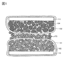
- FIG. 1 is an example of a schematic cross-sectional view of a secondary battery showing one embodiment of the present invention.
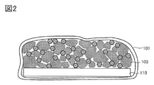
- FIG. 2 is an example of a negative electrode showing one embodiment of the present invention.
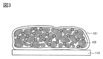
- FIG. 3 is an example of a negative electrode showing one embodiment of the present invention.
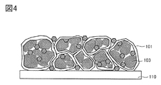
- FIG. 4 is an example of a negative electrode showing one embodiment of the present invention.
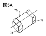
- FIG. 5A is a perspective view of the all-solid-state battery
- FIG. 5B is a sectional view thereof.
- 6A, 6B, 6C, and 6D are perspective views of the all-solid-state battery.
- 7A and 7B are perspective views of the all-solid-state battery.
- 8A, 8B, and 8C are examples of vehicles.
- Solid-state batteries include thin-film all-solid-state batteries and bulk all-solid-state batteries.
- the thin-film all-solid-state battery is an all-solid-state battery obtained by stacking thin films
- the bulk-type all-solid-state battery is an all-solid battery obtained by stacking fine particles.
- FIG. 1 is an example of a bulk type all-solid-state battery.
- the positive electrode active material particles 104 are provided in the vicinity of the positive electrode current collector 111, and the negative electrode active material particles 103 are provided in the vicinity of the negative electrode current collector 110, and the solid electrolyte is filled so as to fill the gaps between them.
- the particles 105 are arranged.
- titanium dioxide TiO 2
- lithium titanium oxide Li 4 Ti 5 O 12
- lithium-graphite intercalation compound Li x C 6
- niobium pentoxide Nb 2 O 5
- Oxides such as tungsten oxide (WO 2 ) and molybdenum oxide (MoO 2 ) can be used.
- the first graphene compound 101 is provided so as to surround the negative electrode current collector 110 and the plurality of negative electrode active material particles 103.
- the negative electrode active material particles or the plurality of negative electrode active material particles are fixed to the negative electrode current collector 110 using the first graphene compound 101.
- generation of by-products precipitates, etc.
- generation of micro shorts is suppressed. can do.
- the first graphene compound 101 also includes a plurality of solid electrolyte particles together with the plurality of negative electrode active material particles 103.
- a layer composed of a plurality of solid electrolyte particles 105 is provided between a positive electrode current collector 111 and a negative electrode current collector 110, and the solid electrolyte particles 105 and the first graphene compound 101 surround the layer.
- An example is shown in which the same component as the solid electrolyte particles used is used.
- a structure including at least the positive electrode current collector 111 and the positive electrode active material particles 104 functions as a positive electrode, and the positive electrode is surrounded by the second graphene compound 102.
- FIG. 1 illustrates an example in which a material having the same components as the solid electrolyte particles 105 and the solid electrolyte particles wrapped with the second graphene compound 102 is used.
- the distance between the first graphene compound 101 and the second graphene compound 102 depends on the material of the solid electrolyte particles 105, but is 0.1 ⁇ m or more and 1 mm or less, preferably 1 ⁇ m or more and 100 ⁇ m or less.
- FIG. 2 shows a schematic cross-sectional view after encapsulating the solid electrolyte particles, the negative electrode active material particles 103, and the negative electrode current collector 110 with the first graphene compound 101. After obtaining the state shown in FIG. 2, a firing or pressing process may be performed.
- the reduced graphene oxide that surrounds the negative electrode current collector 110, the solid electrolyte particles, and the negative electrode active material particles 103 ( RGO) is attached.
- graphene having an alkali metal or graphene having an element other than carbon such as oxygen may be referred to as a graphene analog.
- the graphene compound also includes a graphene analog.
- Graphene compounds include graphene quantum dots.
- each solid electrolyte particle is illustrated as being the same.
- a plurality of types of particles may be filled between the positive electrode current collector 111 and the negative electrode current collector 110 by a pressure press so that voids are eliminated as much as possible.
- the laminate shown in FIG. 1 is obtained.
- the laminated body is subjected to a heat treatment or a pressing step to improve the denseness.
- an all-solid-state battery can be manufactured.
- This embodiment mode can be freely combined with Embodiment Mode 1.
- FIG. 4 illustrates a structure in which a plurality of groups surrounded by the first graphene, specifically, the solid electrolyte particles and the negative electrode active material particles 103 are surrounded by the first graphene compound 101. In FIG. 4, seven groups are shown. Further, solid electrolyte particles are arranged in the gaps.
- An all-solid-state battery can be manufactured by stacking the negative electrode shown in FIG. 4 and the positive electrode shown in Embodiment Mode 1 in combination.
- an all-solid-state battery may be manufactured by forming a positive electrode without wrapping the positive electrode current collector with the second graphene compound 102 and then stacking the positive electrode current collector with the negative electrode in FIG.
- Embodiment Mode can be freely combined with Embodiment Mode 1 or Embodiment Mode 2.
- lithium fluoride LiF is prepared as the fluorine source and the lithium source
- magnesium fluoride MgF 2 is prepared as the fluorine source and the magnesium source (step S11 in FIG. 11).
- ketone such as acetone
- alcohol such as ethanol and isopropanol
- ether dioxane
- acetonitrile N-methyl-2-pyrrolidone (NMP) and the like
- NMP N-methyl-2-pyrrolidone
- acetone is used (see step S11 in FIG. 11).
- a lithium source is prepared as shown in step S25.
- a composite oxide containing lithium, a transition metal and oxygen which is synthesized in advance is used as the step S25.
- lithium cobalt oxide particles (trade name: Cell Seed C-10N) manufactured by Nippon Kagaku Kogyo Co., Ltd. can be used as the lithium cobalt oxide synthesized in advance.
- This has an average particle diameter (D50) of about 12 ⁇ m, and in the impurity analysis by glow discharge mass spectrometry (GD-MS), magnesium concentration and fluorine concentration are 50 ppm wt or less, calcium concentration, aluminum concentration and silicon concentration are 100 ppm wt.
- lithium cobalt oxide having a nickel concentration of 150 ppm wt or less, a sulfur concentration of 500 ppm wt or less, an arsenic concentration of 1100 ppm wt or less, and other element concentrations other than lithium, cobalt and oxygen of 150 ppm wt or less.
- the mixture 902 and a composite oxide containing lithium, a transition metal and oxygen are mixed (step S31 in FIG. 11).
- the mixing in step S31 is preferably performed under milder conditions than the mixing in step S12 so as not to destroy the particles of the composite oxide.
- the number of rotations is shorter or the time is shorter than that in the mixing in step S12.
- the dry method is more mild than the wet method.
- a ball mill, a bead mill, or the like can be used for mixing. When using a ball mill, for example, it is preferable to use zirconia balls as the medium.
- step S32 in FIG. 11 The materials mixed above are collected (step S32 in FIG. 11) to obtain a mixture 903 (step S33 in FIG. 11).
- the mixture 903 is heated.
- This step may be referred to as annealing or second heating in order to distinguish it from the previous heating step.
- Anneal is preferably performed at an appropriate temperature and time.
- the appropriate temperature and time vary depending on the conditions such as the size and composition of the particles of the composite oxide containing lithium, transition metal and oxygen in step S25. For smaller particles, lower temperatures or shorter times may be more preferable than larger particles.
- the annealing temperature is preferably 600° C. or higher and 950° C. or lower.
- the annealing time is, for example, preferably 1 hour or more and 10 hours or less, more preferably about 2 hours.
- the temperature reduction time after annealing is preferably, for example, 10 hours or more and 50 hours or less.
- magnesium and halogen have a higher concentration in the surface layer portion and near the grain boundaries than in the inside.
- the magnesium concentration in the surface layer portion and near the grain boundaries is high, the change in crystal structure can be suppressed more effectively.
- step S35 in FIG. 11 The material annealed as described above is collected (step S35 in FIG. 11) to obtain the mixture 904 (step S36 in FIG. 11).
- step S50 The materials mixed in step S50 are collected in step S51 to obtain a mixture 905 (step S52 in FIG. 11).
- a metal source is prepared.
- a solvent used for the sol-gel method is prepared.
- the metal source metal alkoxide, metal hydroxide, metal oxide or the like can be used.
- the metal Z is aluminum, for example, the number of cobalt atoms contained in lithium cobalt oxide may be 1, and the concentration of aluminum contained in the metal source may be 0.001 times or more and 0.02 times or less.
- the metal Z is nickel, the number of cobalt atoms contained in lithium cobalt oxide may be set to 1 and the concentration of nickel contained in the metal source may be 0.001 times or more and 0.02 times or less.
- the concentration of aluminum contained in the metal source is 0.001 times or more and 0.02 times or less, and the metal source has The nickel concentration may be 0.001 times or more and 0.02 times or less.
- sol-gel method is applied, and aluminum isopropoxide is used as the metal source and isopropanol is used as the solvent.
- step S53 in FIG. 11 the aluminum alkoxide is dissolved in alcohol, and lithium cobalt oxide particles are further mixed.
- Requirement of metal alkoxide varies depending on the particle size of lithium cobalt oxide.
- the particle size (D50) of lithium cobalt oxide is about 20 ⁇ m
- the number of cobalt atoms of lithium cobalt oxide is 1
- the aluminum concentration of aluminum isopropoxide is 0.001. It is preferable to add it so as to be not less than twice and not more than 0.02 times.
- the stirring can be performed, for example, with a magnetic stirrer.
- the stirring time may be a time sufficient for the water and metal alkoxide in the atmosphere to undergo a hydrolysis and polycondensation reaction, for example, 4 hours, 25° C., humidity 90% RH (Relative Humidity, relative humidity) conditions You can do it below.
- the stirring may be performed in an atmosphere in which humidity control and temperature control are not performed, for example, in an air atmosphere in the draft chamber. In such a case, it is preferable to make the stirring time longer, for example, 12 hours or more at room temperature.
- the sol-gel reaction By reacting water vapor in the atmosphere with metal alkoxide, the sol-gel reaction can proceed more slowly than when liquid water is added. Further, by reacting the metal alkoxide with water at room temperature, the sol-gel reaction can proceed more slowly than in the case of heating at a temperature higher than the boiling point of the solvent alcohol, for example. By slowly advancing the sol-gel reaction, a coating layer having a uniform thickness and good quality can be formed.
- Precipitate is recovered from the mixed liquid after the above processing (step S54 in FIG. 11).
- filtration, centrifugation, evaporation to dryness, or the like can be applied.
- the precipitate can be washed with the same alcohol as the solvent in which the metal alkoxide is dissolved.
- the solvent and the precipitate need not be separated in this step, and the precipitate may be recovered in the drying step of the next step (step S54), for example.
- step S54 in FIG. 11 vacuum or ventilation drying can be performed at 80° C. for 1 hour or more and 4 hours or less.
- the heating temperature is less than 1000°C, preferably 700°C or more and 950°C or less, and more preferably about 850°C.
- heating is preferably performed in an atmosphere containing oxygen.
- the heating temperature in step S55 is preferably lower than the heating temperature in step S34.
- any of the mixtures 902, 903, 904, 905, and 906 obtained by the above manufacturing process can be used as a positive electrode active material.
- the mixture 902 is a positive electrode active material material having a lithium component, a magnesium component, and a fluorine component
- the mixtures 903 and 904 are positive electrode active material materials having a lithium component, a cobalt component, a magnesium component, and a fluorine component.
- the mixture 905 is a positive electrode active material having a lithium component, a cobalt component, a magnesium component, a nickel component, and a fluorine component
- the mixture 906 is a lithium component, a cobalt component, a magnesium component, a nickel component, an aluminum component, and It is a positive electrode active material having a fluorine component.
- a solid-state battery can be manufactured by combining with the first embodiment.
- the sealed container of the all-solid-state battery it is preferable to use a package having excellent airtightness, and a ceramic package or a resin package is used. Moreover, it is preferable that the sealing is performed in a closed atmosphere, for example, in a glove box, by blocking the outside air.
- FIG. 5A shows a perspective view of an all solid state secondary battery having external electrodes 71 and 72 and sealed with a package member.
- Such an all-solid-state secondary battery can be directly mounted on a circuit board or the like.
- the laminated structure has a structure in which a package member 70a having a flat plate provided with an electrode layer 73a, a frame-shaped package member 70b, and a package member 70c having a flat plate provided with the electrode layer 73b are surrounded and sealed. ing.
- an insulating material such as a resin material or ceramic can be used.
- the external electrode 71 is electrically connected to the positive electrode layer 50a via the electrode layer 73a and functions as a positive electrode.
- the external electrode 72 is electrically connected to the negative electrode layer 50c via the electrode layer 73b and functions as a negative electrode.
- 6A, 6B, 6C, and 6D show an example of manufacturing a laminated secondary battery which is different from the packaging method shown in FIG. 5A.
- FIG. 6A shows an external view of the positive electrode 503 and the negative electrode 506.
- the positive electrode 503 has a positive electrode current collector 501, and the positive electrode active material layer 502 is formed on the surface of the positive electrode current collector 501. Further, the positive electrode 503 has a region where the positive electrode current collector 501 is partially exposed (hereinafter referred to as a tab region).
- the negative electrode 506 has a negative electrode current collector 504, and the negative electrode active material layer 505 is formed on the surface of the negative electrode current collector 504.
- the negative electrode 506 has a region where the negative electrode current collector 504 is partially exposed, that is, a tab region.
- the area and shape of the tab regions included in the positive electrode and the negative electrode are not limited to the example shown in FIG. 6A.
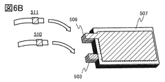
- FIG. 6B shows the negative electrode 506, the solid electrolyte layer 507, and the positive electrode 503 that are stacked.
- FIG. 6B shows the negative electrode 506, the solid electrolyte layer 507, and the positive electrode 503 that are stacked.
- an example in which five negative electrodes and four positive electrodes are used is shown.
- the tab regions of the positive electrode 503 are joined together, and the positive electrode lead electrode 510 is joined to the tab region of the positive electrode on the outermost surface.
- ultrasonic welding may be used.
- the tab regions of the negative electrode 506 are joined together, and the negative electrode lead electrode 511 is joined to the tab region of the outermost negative electrode.
- the solid electrolyte layer 507 may be a material layer (ceramic or the like) containing a solid component capable of conducting lithium ions.
- the solid electrolyte layer 507 is formed by slurrying ceramic powder or glass powder into a sheet.
- the definition of ceramic is a material of inorganic compounds such as oxides, carbides, nitrides, borides, regardless of metal or non-metal. Glass is amorphous and is defined as a material having a glass transition phenomenon, but a material obtained by making it into a microcrystal is sometimes called ceramic glass.
- the ceramic glass has crystallinity, it can be confirmed by an X-ray diffraction method.
- the solid electrolyte an oxide solid electrolyte, a sulfide solid electrolyte, or the like can be used.
- the positive electrode active material layer 502 and the negative electrode active material layer 505 also contain a solid electrolyte and may contain a conductive auxiliary agent.
- the conductive additive may be a material having electronic conductivity, and for example, a carbon material, a metal material or the like can be used.
- oxide solid electrolyte used as the negative electrode active material particles examples include Nb 2 O 5 , Li 4 Ti 5 O 12 and SiO.
- SiO refers to, for example, silicon monoxide.
- SiO refers to a material having a larger composition of silicon as compared with SiO 2, and can also be represented as SiO x .
- x preferably has a value near 1.
- x is preferably 0.2 or more and 1.5 or less, and more preferably 0.3 or more and 1.2 or less.
- the exterior body 509 is bent at the portion indicated by the broken line. Then, the outer peripheral portion of the exterior body 509 is joined.
- a laminated film in which a metal foil and an organic resin film are stacked for example, an aluminum foil or a stainless foil is used, and for bonding, for example, thermocompression bonding or the like may be used.
- the laminated secondary battery 500 shown in FIG. 6D can be manufactured.
- two laminated films may be stacked and the peripheral edge portions may be adhered and sealed.
- a plurality of laminate type secondary batteries 500 can be mounted as one battery module in an electric vehicle or the like.
- FIG. 7A is a perspective view showing a state in which three laminate type secondary batteries 500 are sandwiched and fixed between the first plate 521 and the second plate 524.
- FIG. 7B by fixing the distance between the first plate 521 and the second plate 524 using the fixtures 525a and 525b, it is possible to pressurize the three secondary batteries 500. it can.
- FIGS. 7A and 7B show an example in which three laminate type secondary batteries 500 are used, the number is not particularly limited, and four or more secondary batteries 500 can be used. It can be used as a power source for a small vehicle, and if it is used 100 or more, it can also be used as a large-sized vehicle power source. Further, a protective circuit for preventing overcharge or a temperature sensor for monitoring a temperature rise may be provided in the laminated secondary battery 500.
- the shape of the secondary battery is not limited to the laminate type, and may be a coin type, a cylinder type, a square type, or the like.
- an all-solid-state battery by applying a predetermined pressure in the stacking direction of the stacked positive and negative electrodes, it is possible to maintain a good contact state of the interface inside.
- a predetermined pressure in the stacking direction of the positive electrode and the negative electrode expansion of the all-solid-state battery in the stacking direction due to charge/discharge can be suppressed, and the reliability of the all-solid-state battery can be improved.
- Vehicles include, for example, automobiles, motorcycles, bicycles, and the like.
- FIG. 8 illustrates a vehicle using the all solid state secondary battery which is one embodiment of the present invention.
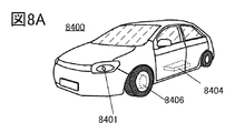
- a vehicle 8400 shown in FIG. 8A is an electric vehicle that uses an electric motor as a power source for traveling. Alternatively, it is a hybrid vehicle in which an electric motor and an engine can be appropriately selected and used as a power source for traveling.
- the automobile 8400 has a power storage system including an all-solid-state secondary battery 8404.
- the all-solid-state secondary battery 8404 can not only drive the electric motor 8406 but can also supply power to a light-emitting device such as a headlight 8401 or a room light (not shown). Further, in order to prevent the electric power supply from being stopped and the hazard lamp from being turned off due to an abnormality in the all-solid-state secondary battery 8404, it is preferable that the vehicle be provided with a secondary battery that is independent from that for driving.
- the all-solid-state secondary battery 8404 can supply power to a display device such as a speedometer and a tachometer of the automobile 8400.
- the all-solid-state secondary battery 8404 can supply power to a navigation system included in the automobile 8400.
- the automobile 8500 shown in FIG. 8B can be charged by receiving power supply from an external charging facility to the all-solid-state secondary battery of the automobile 8500 by a plug-in method, a contactless power feeding method, or the like.
- FIG. 8B shows a state in which an all-solid secondary battery 8024 mounted on an automobile 8500 is being charged from a ground-installed charging device 8021 via a cable 8022.
- the charging method, the standard of the connector and the like may be appropriately performed by a predetermined method such as CHAdeMO (registered trademark) or combo.
- the charging device 8021 may be a charging station provided in a commercial facility or may be a home power source.
- the plug-in technology can charge the all-solid-state secondary battery 8024 mounted on the automobile 8500 by external power supply. Charging can be performed by converting AC power into DC power via a converter such as an ACDC converter.
- the all-solid secondary battery 8024 the all-solid secondary battery described in Embodiment 2 is used.
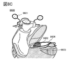
- FIG. 8C is an example of a motorcycle using the all-solid-state secondary battery of one embodiment of the present invention.
- the scooter 8600 shown in FIG. 8C includes an all-solid-state secondary battery 8602, a side mirror 8601, and a direction indicator light 8603.
- the all-solid secondary battery 8602 can supply electricity to the direction indicator light 8603.
- the scooter 8600 shown in FIG. 8C can store the all-solid-state secondary battery 8602 in the under-seat storage 8604.
- the all-solid-state secondary battery 8602 can be stored in the under-seat storage 8604 even if the under-seat storage 8604 is small.
- the mobile phone 2100 can execute various applications such as mobile phone, e-mail, text browsing and creation, music playback, Internet communication, and computer games.
- the operation button 2103 can have various functions such as power on/off operation, wireless communication on/off operation, manner mode execution/cancellation, and power saving mode execution/cancellation in addition to time setting. ..
- the function of the operation button 2103 can be freely set by the operating system incorporated in the mobile phone 2100.
- the mobile phone 2100 can execute near field communication that is a communication standard. For example, by communicating with a headset capable of wireless communication, a hands-free call can be made.
- the mobile phone 2100 preferably has a sensor.
- a human body sensor such as a fingerprint sensor, a pulse sensor, a body temperature sensor, a touch sensor, a pressure sensor, an acceleration sensor, or the like is preferably mounted as the sensor.
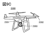
- FIG. 9C is an unmanned aerial vehicle 2300 having a plurality of rotors 2302.
- the unmanned aerial vehicle 2300 includes a solid-state battery 2301 which is one embodiment of the present invention, a camera 2303, and an antenna (not illustrated).
- the unmanned aerial vehicle 2300 can be remotely controlled via an antenna. Since the solid state battery of one embodiment of the present invention has high safety, it can be used safely for a long period of time and is suitable as a solid state battery to be mounted on the unmanned aerial vehicle 2300.
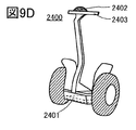
- FIG. 9D shows an electric motorcycle 2400 using the solid-state battery of one embodiment of the present invention.
- the electric motorcycle 2400 includes a solid-state battery 2401, which is one embodiment of the present invention, a display portion 2402, and a handle 2403.
- the solid-state battery 2401 can supply electricity to a motor that serves as a power source.
- the display unit 2402 can display the remaining amount of the solid battery 2401, the speed of the electric motorcycle 2400, the horizontal state, and the like.
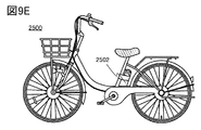
- FIG. 9E is an example of an electric bicycle using the solid-state battery of one embodiment of the present invention.
- the electric bicycle 2500 includes a battery pack 2502.
- the battery pack 2502 includes the solid-state battery of one embodiment of the present invention.
- the battery pack 2502 can supply electricity to a motor that assists the driver. Further, the battery pack 2502 can be removed from the electric bicycle 2500 and carried. Further, the battery pack 2502 and the electric bicycle 2500 may have a display portion that can display the remaining battery level and the like.
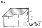
- the house illustrated in FIG. 10 includes a power storage system 2612 including a solid-state battery which is one embodiment of the present invention and a solar panel 2610.
- the power storage system 2612 is electrically connected to the solar panel 2610 via a wiring 2611 and the like. Further, the power storage system 2612 and the ground-installed charging device 2604 may be electrically connected. Electric power obtained from the solar panel 2610 can be charged into the power storage system 2612. Further, the electric power stored in the power storage system 2612 can be charged into the solid state battery 2602 included in the vehicle 2603 through the charging device 2604.
- the electric power stored in the power storage system 2612 can also supply electric power to other electronic devices in the house. Therefore, even when power cannot be supplied from a commercial power source due to a power failure or the like, the electronic device can be used by using the power storage system 2612 according to one embodiment of the present invention as an uninterruptible power source.
- 50a positive electrode layer, 50b: solid electrolyte layer, 50c: negative electrode layer, 70a: package member, 70b: package member, 70c: package member, 71: external electrode, 72: external electrode, 73a: electrode layer, 73b: electrode layer , 101: first graphene compound, 102: second graphene compound, 103: negative electrode active material particles, 104: positive electrode active material particles, 105: solid electrolyte particles, 110: negative electrode current collector, 111: positive electrode current collector Current collector, 500: secondary battery, 501: positive electrode current collector, 502: positive electrode active material layer, 503: positive electrode, 504: negative electrode current collector, 505: negative electrode active material layer, 506: negative electrode, 507: solid electrolyte layer , 509: exterior body, 510: positive electrode lead electrode, 511: negative electrode lead electrode, 521: plate, 524: plate, 525a: fixing device, 525b: fixing device, 902: mixture, 903: mixture, 904: mixture, 905
Landscapes
- Chemical & Material Sciences (AREA)
- Chemical Kinetics & Catalysis (AREA)
- Electrochemistry (AREA)
- General Chemical & Material Sciences (AREA)
- Engineering & Computer Science (AREA)
- Manufacturing & Machinery (AREA)
- Materials Engineering (AREA)
- Inorganic Chemistry (AREA)
- General Physics & Mathematics (AREA)
- Condensed Matter Physics & Semiconductors (AREA)
- Physics & Mathematics (AREA)
- Composite Materials (AREA)
- Secondary Cells (AREA)
- Battery Electrode And Active Subsutance (AREA)
Abstract
Description
図2は本発明の一態様を示す負極の一例である。
図3は本発明の一態様を示す負極の一例である。
図4は本発明の一態様を示す負極の一例である。
図5Aは全固体電池の斜視図であり、図5Bはその断面図を示す図である。
図6A、図6B、図6C、図6Dは、全固体電池の斜視図を示す図である。
図7A、図7Bは全固体電池の斜視図を示す図である。
図8A、図8B、図8Cは車両の一例である。
図9A、図9B、図9C、図9D、図9Eは電子機器の一例を示す斜視図である。
図10は蓄電装置の一例を示す斜視図である。
図11は、正極活物質の作製方法の一例を説明する図である。
本実施の形態では、正極と、酸化物固体電解質と、負極と、該負極の表面に対して、還元された酸化グラフェンを付着させて固定し、充放電よる膨張収縮を抑え、且つ、イオン伝導度を向上させた全固体二次電池を作製する一例を示す。
本実施の形態では、実施の形態1と一部異なる例を図3を用いて以下に説明する。
本実施の形態では、実施の形態1と一部異なる例を図4を用いて以下に説明する。
本実施の形態では、正極の作製方法の一例を示す。
次に、冷却された粒子を回収する(図11のステップS56)。さらに、粒子をふるいにかけることが好ましい。上記の工程で、正極活物質とすることのできる混合物906を作製することができる(図11のステップS57)。
実施の形態1に示した図1は固体電池の断面構造の概念を示す図であり、正極用集電体111と負極用集電体110の間に固体電解質粒子105を有する。第1のグラフェン化合物101での包み方は、図2、図3、図4のいずれか一を選択することができる。
本実施の形態では、車両に本発明の一態様である全固体二次電池を搭載する例を示す。車両として例えば自動車、二輪車、自転車、等が挙げられる。
本実施の形態では、図9および図10を用いて、先の実施の形態で説明した固体電池を電子機器に実装する例について説明する。
Claims (9)
- キャリアイオンを含む正極活物質粒子と、
複数の負極活物質粒子と、
複数の固体電解質粒子と、
グラフェン化合物と、を少なくとも有し、
前記グラフェン化合物は前記負極活物質粒子を固定し、充電時にキャリアイオンは前記グラフェン化合物を通過して前記負極活物質粒子に取り込まれる全固体電池。 - キャリアイオンを含む複数の正極活物質粒子と、
複数の負極活物質粒子と、
複数の固体電解質粒子と、
複数のグラフェン化合物と、を有し、
1つまたは複数の負極活物質粒子を1つまたは複数のグラフェン化合物で固定する全固体電池。 - キャリアイオンを含む複数の正極活物質粒子と、
複数の負極活物質粒子と、
複数の固体電解質粒子と、
複数のグラフェン化合物と、を有し、
1つまたは複数の正極活物質粒子を1つまたは複数のグラフェン化合物で固定する全固体電池。 - キャリアイオンを含む複数の正極活物質粒子と複数の第1の固体電解質粒子との両方を第1のグラフェン化合物で少なくとも一部または全部包み、
複数の負極活物質粒子と複数の第2の固体電解質粒子との両方を第2のグラフェン化合物で少なくとも一部または全部包み、
前記第1のグラフェンと重なる前記第2のグラフェン化合物の間に第3の固体電解質粒子を有する全固体電池。 - キャリアイオンを含む複数の正極活物質粒子と複数の第1の固体電解質粒子を第1のグラフェン化合物で包んだ複数の群が互いに隣接し、
複数の負極活物質粒子と複数の第2の固体電解質粒子を第2のグラフェン化合物で包み、
前記第1のグラフェン化合物の群と重なる前記第2のグラフェン化合物の間に第3の固体電解質粒子を有する全固体電池。 - 請求項4または請求項5において、前記第1、第2、及び第3の固体電解質粒子は同一成分を有する全固体電池。
- 請求項1乃至5のいずれか一において、キャリアイオンはリチウムイオンまたはナトリウムイオンである全固体電池。
- 請求項1乃至7のいずれか一において、前記正極活物質粒子は、コバルト、ニッケル、マグネシウム、マンガン、アルミニウムのいずれか一を含む全固体電池。
- 請求項1乃至8のいずれか一において、前記負極活物質粒子は、シリコン、チタン、炭素のいずれか一を含む全固体電池。
Priority Applications (8)
| Application Number | Priority Date | Filing Date | Title |
|---|---|---|---|
| KR1020217026227A KR20210118118A (ko) | 2019-01-25 | 2020-01-14 | 전고체 전지 및 그 제작 방법 |
| US17/424,296 US12142765B2 (en) | 2019-01-25 | 2020-01-14 | All-solid-state battery and manufacturing method thereof |
| JP2020567661A JP7508377B2 (ja) | 2019-01-25 | 2020-01-14 | 全固体電池 |
| CN202080010797.7A CN113348568A (zh) | 2019-01-25 | 2020-01-14 | 全固态电池及其制造方法 |
| DE112020000514.3T DE112020000514T5 (de) | 2019-01-25 | 2020-01-14 | Gesamtfestkörperbatterie und Herstellungsverfahren dafür |
| JP2024098674A JP7720451B2 (ja) | 2019-01-25 | 2024-06-19 | 電池 |
| US18/935,745 US20250062349A1 (en) | 2019-01-25 | 2024-11-04 | All-solid-state battery and manufacturing method thereof |
| JP2025125794A JP2025157555A (ja) | 2019-01-25 | 2025-07-28 | 電池 |
Applications Claiming Priority (2)
| Application Number | Priority Date | Filing Date | Title |
|---|---|---|---|
| JP2019-010953 | 2019-01-25 | ||
| JP2019010953 | 2019-01-25 |
Related Child Applications (2)
| Application Number | Title | Priority Date | Filing Date |
|---|---|---|---|
| US17/424,296 A-371-Of-International US12142765B2 (en) | 2019-01-25 | 2020-01-14 | All-solid-state battery and manufacturing method thereof |
| US18/935,745 Continuation US20250062349A1 (en) | 2019-01-25 | 2024-11-04 | All-solid-state battery and manufacturing method thereof |
Publications (1)
| Publication Number | Publication Date |
|---|---|
| WO2020152540A1 true WO2020152540A1 (ja) | 2020-07-30 |
Family
ID=71736438
Family Applications (1)
| Application Number | Title | Priority Date | Filing Date |
|---|---|---|---|
| PCT/IB2020/050243 Ceased WO2020152540A1 (ja) | 2019-01-25 | 2020-01-14 | 全固体電池及びその作製方法 |
Country Status (6)
| Country | Link |
|---|---|
| US (2) | US12142765B2 (ja) |
| JP (3) | JP7508377B2 (ja) |
| KR (1) | KR20210118118A (ja) |
| CN (1) | CN113348568A (ja) |
| DE (1) | DE112020000514T5 (ja) |
| WO (1) | WO2020152540A1 (ja) |
Families Citing this family (8)
| Publication number | Priority date | Publication date | Assignee | Title |
|---|---|---|---|---|
| US12272784B2 (en) * | 2020-08-27 | 2025-04-08 | Toyota Motor Engineering & Manufacturing North America, Inc. | Ceramic-soft composites for solid-state silicon anodes |
| KR102703495B1 (ko) * | 2021-11-03 | 2024-09-05 | 이상천 | 에너지밀도 및 안전도가 향상된 그래핀 전고체 배터리 및 그 제조방법 |
| GB2620391A (en) * | 2022-07-04 | 2024-01-10 | Petroliam Nasional Berhad Petronas | Lithium battery |
| CN115069103A (zh) * | 2022-08-09 | 2022-09-20 | 南通市盛远石墨烯新材料有限公司 | 一种高分散稳定型石墨烯复合导电浆料制备设备 |
| KR102493809B1 (ko) * | 2022-09-26 | 2023-01-30 | 황성원 | 고체 전해질, 전고체 리튬이차전지 및 이의 제조방법 |
| KR102545572B1 (ko) * | 2022-09-27 | 2023-06-29 | (주)바이오제네시스 | 하이브리드 그래핀 양극이 포함된 배터리 |
| WO2025009876A1 (ko) * | 2023-07-03 | 2025-01-09 | 주식회사 그래피니드테크놀로지 | 전극 첨가제, 이를 포함하는 리튬 이차전지용 음극 및 리튬 이차전지용 음극의 제조방법 |
| CN118598662A (zh) * | 2024-05-24 | 2024-09-06 | 华中科技大学 | 碱金属电池用固态电解质的一体化烧结成型方法及产品 |
Citations (3)
| Publication number | Priority date | Publication date | Assignee | Title |
|---|---|---|---|---|
| JP2013229315A (ja) * | 2012-03-29 | 2013-11-07 | Semiconductor Energy Lab Co Ltd | リチウムイオン二次電池の作製方法 |
| JP2016528678A (ja) * | 2013-07-03 | 2016-09-15 | カリフォルニア インスティチュート オブ テクノロジー | セパレータフリー型シリコン‐硫黄電池用カーボンナノチューブ‐グラフェンハイブリッド構造 |
| JP2018098200A (ja) * | 2016-12-09 | 2018-06-21 | 株式会社半導体エネルギー研究所 | 二次電池およびその作製方法 |
Family Cites Families (11)
| Publication number | Priority date | Publication date | Assignee | Title |
|---|---|---|---|---|
| JPWO2011145462A1 (ja) * | 2010-05-17 | 2013-07-22 | 住友電気工業株式会社 | 非水電解質電池用正極体及びその製造方法、並びに非水電解質電池 |
| WO2011158948A1 (en) | 2010-06-18 | 2011-12-22 | Semiconductor Energy Laboratory Co., Ltd. | Method of manufacturing power storage device |
| US8691441B2 (en) | 2010-09-07 | 2014-04-08 | Nanotek Instruments, Inc. | Graphene-enhanced cathode materials for lithium batteries |
| US9558860B2 (en) | 2010-09-10 | 2017-01-31 | Samsung Electronics Co., Ltd. | Graphene-enhanced anode particulates for lithium ion batteries |
| US8404001B2 (en) | 2011-04-15 | 2013-03-26 | Semiconductor Energy Laboratory Co., Ltd. | Method for manufacturing positive electrode and power storage device |
| KR101972609B1 (ko) | 2011-06-03 | 2019-04-25 | 가부시키가이샤 한도오따이 에네루기 켄큐쇼 | 전극의 제조 방법 |
| CN105174252B (zh) * | 2011-06-24 | 2018-12-14 | 株式会社半导体能源研究所 | 多层石墨烯及蓄电装置 |
| JP6218349B2 (ja) * | 2011-09-30 | 2017-10-25 | 株式会社半導体エネルギー研究所 | 蓄電装置 |
| US9646771B2 (en) | 2012-03-26 | 2017-05-09 | Semiconductor Energy Laboratory Co., Ltd. | Power storage element including positive electrode and negative electrode in the same plane over substrate and power storage device |
| WO2014020654A1 (ja) * | 2012-07-30 | 2014-02-06 | 株式会社 日立製作所 | 全固体イオン二次電池 |
| CN107579239B (zh) | 2017-09-13 | 2019-11-12 | 山东大学 | 一种石墨烯/固态电解质复合包覆硅复合负极及其制备方法 |
-
2020
- 2020-01-14 KR KR1020217026227A patent/KR20210118118A/ko active Pending
- 2020-01-14 DE DE112020000514.3T patent/DE112020000514T5/de active Pending
- 2020-01-14 JP JP2020567661A patent/JP7508377B2/ja active Active
- 2020-01-14 CN CN202080010797.7A patent/CN113348568A/zh active Pending
- 2020-01-14 US US17/424,296 patent/US12142765B2/en active Active
- 2020-01-14 WO PCT/IB2020/050243 patent/WO2020152540A1/ja not_active Ceased
-
2024
- 2024-06-19 JP JP2024098674A patent/JP7720451B2/ja active Active
- 2024-11-04 US US18/935,745 patent/US20250062349A1/en active Pending
-
2025
- 2025-07-28 JP JP2025125794A patent/JP2025157555A/ja active Pending
Patent Citations (3)
| Publication number | Priority date | Publication date | Assignee | Title |
|---|---|---|---|---|
| JP2013229315A (ja) * | 2012-03-29 | 2013-11-07 | Semiconductor Energy Lab Co Ltd | リチウムイオン二次電池の作製方法 |
| JP2016528678A (ja) * | 2013-07-03 | 2016-09-15 | カリフォルニア インスティチュート オブ テクノロジー | セパレータフリー型シリコン‐硫黄電池用カーボンナノチューブ‐グラフェンハイブリッド構造 |
| JP2018098200A (ja) * | 2016-12-09 | 2018-06-21 | 株式会社半導体エネルギー研究所 | 二次電池およびその作製方法 |
Also Published As
| Publication number | Publication date |
|---|---|
| KR20210118118A (ko) | 2021-09-29 |
| CN113348568A (zh) | 2021-09-03 |
| US12142765B2 (en) | 2024-11-12 |
| JP7508377B2 (ja) | 2024-07-01 |
| JP2025157555A (ja) | 2025-10-15 |
| US20250062349A1 (en) | 2025-02-20 |
| JPWO2020152540A1 (ja) | 2020-07-30 |
| JP2024111153A (ja) | 2024-08-16 |
| US20220115661A1 (en) | 2022-04-14 |
| DE112020000514T5 (de) | 2021-10-07 |
| JP7720451B2 (ja) | 2025-08-07 |
Similar Documents
| Publication | Publication Date | Title |
|---|---|---|
| JP7720451B2 (ja) | 電池 | |
| JP7466718B2 (ja) | リチウムイオン二次電池 | |
| CN110277556B (zh) | 活性物质、电极、二次电池、电池组以及车辆 | |
| CN110364696B (zh) | 电极、二次电池、电池组和车辆 | |
| CN110911659B (zh) | 活性物质、电极、二次电池、电池包及车辆 | |
| JP2023015339A (ja) | 固体電池 | |
| JP2021093356A (ja) | 正極活物質、二次電池、電子機器 | |
| JP7638634B2 (ja) | 二次電池 | |
| CN113165908A (zh) | 正极活性物质及二次电池 | |
| WO2022034414A1 (ja) | 二次電池、電子機器、車両、及び正極活物質の作製方法 | |
| JP2022045353A (ja) | 二次電池の作製方法、および二次電池 | |
| JP6622242B2 (ja) | 電極構造体、電極、二次電池、組電池、電池パック、及び車両 | |
| WO2021245562A1 (ja) | 正極活物質、正極活物質層、二次電池、電子機器、及び車両 | |
| WO2022038449A1 (ja) | 二次電池、電子機器および車両 | |
| WO2022038454A1 (ja) | 正極活物質の作製方法 | |
| WO2022038451A1 (ja) | 正極活物質の作製方法、および二次電池の作製方法 | |
| WO2021144660A1 (ja) | 正極活物質、二次電池、電子機器、および車両 | |
| JP2022035302A (ja) | 二次電池およびその作製方法、および車両 | |
| JP2022045263A (ja) | 正極活物質、二次電池、二次電池の作製方法、電子機器、及び車両 | |
| US20240234718A1 (en) | Method for forming positive electrode active material, positive electrode, lithium-ion secondary battery, moving vehicle, power storage device, and electronic device | |
| KR20230138499A (ko) | 양극 활물질의 제작 방법, 이차 전지, 및 차량 | |
| WO2022023865A1 (ja) | 二次電池及びその作製方法 | |
| WO2023079399A1 (ja) | 二次電池 | |
| WO2017195071A1 (ja) | 蓄電装置用負極、蓄電装置、および電気機器 |
Legal Events
| Date | Code | Title | Description |
|---|---|---|---|
| 121 | Ep: the epo has been informed by wipo that ep was designated in this application |
Ref document number: 20744476 Country of ref document: EP Kind code of ref document: A1 |
|
| ENP | Entry into the national phase |
Ref document number: 2020567661 Country of ref document: JP Kind code of ref document: A |
|
| ENP | Entry into the national phase |
Ref document number: 20217026227 Country of ref document: KR Kind code of ref document: A |
|
| 122 | Ep: pct application non-entry in european phase |
Ref document number: 20744476 Country of ref document: EP Kind code of ref document: A1 |