WO2020148967A1 - 画像形成装置、画像形成プログラム、および画像形成方法 - Google Patents
画像形成装置、画像形成プログラム、および画像形成方法 Download PDFInfo
- Publication number
- WO2020148967A1 WO2020148967A1 PCT/JP2019/042788 JP2019042788W WO2020148967A1 WO 2020148967 A1 WO2020148967 A1 WO 2020148967A1 JP 2019042788 W JP2019042788 W JP 2019042788W WO 2020148967 A1 WO2020148967 A1 WO 2020148967A1
- Authority
- WO
- WIPO (PCT)
- Prior art keywords
- image forming
- drum
- forming apparatus
- mode
- control unit
- Prior art date
- Legal status (The legal status is an assumption and is not a legal conclusion. Google has not performed a legal analysis and makes no representation as to the accuracy of the status listed.)
- Ceased
Links
Images







Classifications
-
- G—PHYSICS
- G03—PHOTOGRAPHY; CINEMATOGRAPHY; ANALOGOUS TECHNIQUES USING WAVES OTHER THAN OPTICAL WAVES; ELECTROGRAPHY; HOLOGRAPHY
- G03G—ELECTROGRAPHY; ELECTROPHOTOGRAPHY; MAGNETOGRAPHY
- G03G15/00—Apparatus for electrographic processes using a charge pattern
- G03G15/50—Machine control of apparatus for electrographic processes using a charge pattern, e.g. regulating differents parts of the machine, multimode copiers, microprocessor control
-
- B—PERFORMING OPERATIONS; TRANSPORTING
- B41—PRINTING; LINING MACHINES; TYPEWRITERS; STAMPS
- B41J—TYPEWRITERS; SELECTIVE PRINTING MECHANISMS, i.e. MECHANISMS PRINTING OTHERWISE THAN FROM A FORME; CORRECTION OF TYPOGRAPHICAL ERRORS
- B41J29/00—Details of, or accessories for, typewriters or selective printing mechanisms not otherwise provided for
-
- B—PERFORMING OPERATIONS; TRANSPORTING
- B41—PRINTING; LINING MACHINES; TYPEWRITERS; STAMPS
- B41J—TYPEWRITERS; SELECTIVE PRINTING MECHANISMS, i.e. MECHANISMS PRINTING OTHERWISE THAN FROM A FORME; CORRECTION OF TYPOGRAPHICAL ERRORS
- B41J29/00—Details of, or accessories for, typewriters or selective printing mechanisms not otherwise provided for
- B41J29/38—Drives, motors, controls or automatic cut-off devices for the entire printing mechanism
-
- G—PHYSICS
- G03—PHOTOGRAPHY; CINEMATOGRAPHY; ANALOGOUS TECHNIQUES USING WAVES OTHER THAN OPTICAL WAVES; ELECTROGRAPHY; HOLOGRAPHY
- G03G—ELECTROGRAPHY; ELECTROPHOTOGRAPHY; MAGNETOGRAPHY
- G03G15/00—Apparatus for electrographic processes using a charge pattern
- G03G15/55—Self-diagnostics; Malfunction or lifetime display
- G03G15/553—Monitoring or warning means for exhaustion or lifetime end of consumables, e.g. indication of insufficient copy sheet quantity for a job
- G03G15/556—Monitoring or warning means for exhaustion or lifetime end of consumables, e.g. indication of insufficient copy sheet quantity for a job for toner consumption, e.g. pixel counting, toner coverage detection or toner density measurement
-
- G—PHYSICS
- G06—COMPUTING OR CALCULATING; COUNTING
- G06K—GRAPHICAL DATA READING; PRESENTATION OF DATA; RECORD CARRIERS; HANDLING RECORD CARRIERS
- G06K15/00—Arrangements for producing a permanent visual presentation of the output data, e.g. computer output printers
- G06K15/002—Interacting with the operator
-
- G—PHYSICS
- G06—COMPUTING OR CALCULATING; COUNTING
- G06K—GRAPHICAL DATA READING; PRESENTATION OF DATA; RECORD CARRIERS; HANDLING RECORD CARRIERS
- G06K15/00—Arrangements for producing a permanent visual presentation of the output data, e.g. computer output printers
- G06K15/02—Arrangements for producing a permanent visual presentation of the output data, e.g. computer output printers using printers
- G06K15/14—Arrangements for producing a permanent visual presentation of the output data, e.g. computer output printers using printers by electrographic printing, e.g. xerography; by magnetographic printing
-
- G—PHYSICS
- G06—COMPUTING OR CALCULATING; COUNTING
- G06K—GRAPHICAL DATA READING; PRESENTATION OF DATA; RECORD CARRIERS; HANDLING RECORD CARRIERS
- G06K15/00—Arrangements for producing a permanent visual presentation of the output data, e.g. computer output printers
- G06K15/40—Details not directly involved in printing, e.g. machine management, management of the arrangement as a whole or of its constitutive parts
- G06K15/407—Managing marking material, e.g. checking available colours
- G06K15/4075—Determining remaining quantities of ink or toner
Definitions
- the present disclosure relates to an image forming apparatus, an image forming program, and an image forming method.
- electrophotographic image forming apparatuses such as LED printers have been known.
- This type of image forming apparatus has an apparatus main body, a drum cartridge and a developing cartridge that can be attached to and detached from the apparatus main body.
- a conventional image forming apparatus having an apparatus main body, a drum cartridge, and a developing cartridge is described in, for example, Japanese Patent Application Laid-Open No. 2004-242242.
- the developing cartridge and the drum cartridge are detachably attached to the apparatus body while the developing cartridge is attached to the drum cartridge.
- the developing cartridge and the drum cartridge are consumable items that can be replaced.
- the image forming apparatus described in Patent Document 1 has a life determining unit and a notification unit.
- the life determining means determines the life of the drum cartridge.
- the notification unit reports a message indicating that the drum cartridge is at the end of life when the life determining unit determines that the drum cartridge is at the end of life. As a result, the user can recognize the replacement of the drum cartridge.
- the image forming apparatus described in Patent Document 1 includes a toner consumption amount estimation unit that estimates the toner consumption amount.
- the present disclosure aims to provide a technology that can reduce the user's time and effort when exchanging a consumable cartridge.
- an image forming apparatus having the following configuration. That is, this image forming apparatus includes a frame, a drum cartridge, a developing cartridge, and a controller.
- the drum cartridge is a drum cartridge mounted on the frame and has a photosensitive drum.
- the developing cartridge is a developing cartridge mounted on the frame and has a housing capable of containing toner.
- the control unit causes the image forming apparatus to execute print processing.
- the control unit can execute a drum replacement necessity determination process and a mode switching process.
- the drum replacement necessity determination process determines whether or not the drum cartridge needs to be replaced based on the life information of the drum cartridge.
- the mode switching process switches between the normal print mode and the extended print mode.
- the image forming apparatus In the normal print mode, when it is determined that the drum cartridge does not need to be replaced, the image forming apparatus can be caused to execute a print process. In the extended print mode, when the drum cartridge needs to be replaced, a print process is executed in the image forming apparatus on condition that the developing cartridge mounted on the frame is not replaced with another developing cartridge. It is possible to
- control section is a processor of a main body section of the image forming apparatus.
- the control unit is further mounted on the frame when it is determined that the drum cartridge needs to be replaced. It is possible to execute a toner identification information acquisition process of acquiring and storing the toner identification information which is the identification information of the developed developing cartridge. Further, in the mode switching process, when the control unit determines that the toner identification information of the developing cartridge mounted on the frame is not changed in a state in which the drum cartridge needs to be replaced, the extension printing is performed. It is possible to switch to mode.
- the developing cartridge has a toner memory in which the toner identification information is stored.
- the control unit can acquire the toner identification information from the toner memory.
- the controller causes the frame to change to the frame when it is determined in the toner identification information acquisition process that the drum cartridge needs to be replaced.
- the toner identification information of the mounted developing cartridge is read from the toner memory.
- the control unit further executes a latest toner identification information acquisition process and an extended print mode availability determination process.
- the toner identification information acquisition process the toner identification information of the developing cartridge mounted in the frame is read from the toner memory after the toner identification information acquisition process.
- the extended print mode availability determination process is performed when the toner identification information read in the toner identification information acquisition process and the toner identification information read in the latest toner identification information acquisition process match. Allow setting to extended print mode.
- the control unit executes extension print mode availability determination processing.
- the extension print mode propriety determination process when there is no change in the toner identification information of the developing cartridge mounted on the frame in a state in which the drum cartridge needs to be replaced, the extension print mode is set.
- the setting to the extended print mode is not permitted. The extended print mode availability determination processing is executed.
- the control unit further executes a user selection acceptance process.
- the user selection receiving process when the drum cartridge needs to be replaced, if there is no change in the toner identification information of the developing cartridge mounted on the frame, the transition to the extended print mode is permitted. Ask the user whether to do it.
- the control unit further executes a user preset acceptance process.
- the user preset acceptance process when the toner identification information of the developing cartridge mounted on the frame is not changed in a state where the drum cartridge needs to be replaced, the extension print mode is uniformly changed. The user is allowed to set in advance whether or not the transfer is permitted.
- the image forming apparatus according to any one of the first aspect to the eighth aspect further includes a transport mechanism that transports the printing paper.
- the drum cartridge has a charger that charges the surface of the photosensitive drum.
- the control unit can further execute a print request acceptance process and an extended print command process.
- the print request reception process receives a print request.
- the extended print command processing when the print request is accepted in the state where the extended print mode is set, the same charging bias as in the normal print mode is applied to the charger, and the transport mechanism is operated.
- the print sheet is conveyed at the same sheet feed speed as in the normal print mode, and the image forming apparatus is caused to execute the print processing.
- the extension print mode includes a normal extension mode and a limited extension mode.
- the normal extension mode it is possible to cause the image forming apparatus to execute the printing process with the same charging bias as in the normal printing mode and at the same sheet feeding speed as in the normal printing mode.
- the limited extension mode it is possible to cause the image forming apparatus to execute the printing process with a charging bias lower than that in the normal printing mode and at a sheet feeding speed slower than that in the normal printing mode.
- the control unit can further execute a determination process and an extension mode determination process.
- the determination process evaluates the magnitude of a parameter that affects the life of the photosensitive drum.
- the extension mode determination process when the determination process determines that the first condition is satisfied, the extension print mode is set to the normal extension mode, and the determination process determines a second condition different from the first condition. If it is determined that the condition is satisfied, the extension print mode is set to the limited extension mode.
- the first condition and the second condition are the number of times the discharge abnormality of the charger that charges the photosensitive drum is detected and the identification information, respectively. Is a condition relating to at least one of the number of prints using the developing cartridge, the number of prints in a high temperature and high humidity environment, the number of prints in a low temperature and low humidity environment, the number of paper jam occurrences, and the number of double-sided prints. ..
- the drum cartridge has a drum memory in which drum identification information capable of identifying the drum cartridge is stored.
- the drum memory is associated with the drum identification information, the number of times the discharge abnormality of the charger is detected, the number of prints using the developing cartridge whose identification information does not match predetermined information, and printing in a high temperature and high humidity environment. It is possible to store at least one of the number of sheets, the number of printed sheets in a low temperature and low humidity environment, the number of paper jam occurrences, and the number of double-sided printed sheets.
- the control unit can further execute a determination process and a print disable mode determination process.
- the determination process evaluates the magnitude of a parameter that affects the life of the photosensitive drum. If it is determined in the determination process that the first condition is not satisfied and the second condition that is different from the first condition is not satisfied, the print-disable mode determination process is performed by the image forming apparatus.
- the print disable mode is set to disable printing.
- the drum cartridge uses the cumulative rotation speed of the photosensitive drum or the photosensitive drum.
- the drum life information indicating at least one of the cumulative number of printed sheets that has been printed is stored, and the control unit stores the cumulative rotation number based on the cumulative number of rotations stored in the drum memory or the cumulative number of printed sheets. If the number of printed sheets or the cumulative number of printed sheets is equal to or more than a predetermined threshold value, it is determined that the drum cartridge needs to be replaced.
- an image forming program capable of causing an image forming apparatus including a frame, a drum cartridge, and a developing cartridge to execute print processing according to a set mode.
- the drum cartridge is a drum cartridge mounted on the frame and has a photosensitive drum.
- the developing cartridge is a developing cartridge mounted on the frame and has a housing capable of containing toner.
- the image forming program causes a control unit mounted on the image forming apparatus or an external control unit to execute the following a) and b).
- a drum replacement necessity determination process for determining whether or not the drum cartridge needs to be replaced is executed based on the life information of the drum cartridge.
- a mode switching process for switching between the normal print mode and the extended print mode is executed.
- the image forming apparatus In the normal print mode, when it is determined that the drum cartridge does not need to be replaced, the image forming apparatus can be caused to execute a print process. In the extension print mode, a print process is executed in the image forming apparatus on condition that the developing cartridge mounted on the frame is not replaced with another developing cartridge when the drum cartridge needs to be replaced. It is possible to
- an image forming method capable of causing an image forming apparatus including a frame, a drum cartridge, and a developing cartridge to execute print processing according to a set mode.
- the drum cartridge is a drum cartridge mounted on the frame and has a photosensitive drum.
- the developing cartridge is a developing cartridge mounted on the frame and has a housing capable of containing toner.
- the image forming method has the following steps a) and b). In a), it is determined whether or not the drum cartridge needs to be replaced based on the life information of the drum cartridge. In b), the normal print mode and the extended print mode are switched.
- the image forming apparatus In the normal print mode, when it is determined that the drum cartridge does not need to be replaced, the image forming apparatus can be caused to execute a print process. In the extended print mode, a print process is executed in the image forming apparatus on condition that the developing cartridge mounted on the frame is not replaced with another developing cartridge when the drum cartridge needs to be replaced. It is possible to
- the drum cartridge is not replaced. It is possible to continue the printing process. In other words, it is possible to extend the life of the drum cartridge and continue the printing process while the same developing cartridge is used before and after the end of the life of the drum cartridge. As a result, it is possible to perform the replacement work of the drum cartridge and the developing cartridge at the same time, and to order the replacement drum cartridge and the developing cartridge at the same time. Will be reduced.
- the fifth aspect of the present application it is possible to easily know whether or not the same developing cartridge is used before and after the end of the life of the drum cartridge, by using the toner identification information read from the toner memory.
- the drum cartridge already used beyond its life is extended. Disables printing from the perspective that its use is undesirable. Therefore, it is possible to prevent the quality of printing from being deteriorated due to the drum cartridge being used over its life.
- the image forming apparatus by allowing the user to select whether or not to permit the transition to the extended print mode, the image forming apparatus can be operated according to the user's intention.
- whether or not to permit the transition to the extended print mode can be uniformly determined in advance, and the user's labor and burden can be reduced.
- the eleventh aspect of the present application it is possible to switch between the normal extension mode and the limited extension mode depending on the situation. Therefore, it is possible to prevent the quality of printing from being deteriorated due to the drum cartridge being used over its life.
- the fourteenth aspect of the present application it is possible to disable printing depending on the result of the determination process depending on the situation. Therefore, it is possible to prevent the print quality from being deteriorated due to the print processing being performed over its life when the print processing is unfavorable.
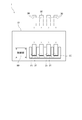
- FIG. 3 is a schematic diagram of an image forming apparatus.
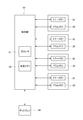
- FIG. 3 is a block diagram showing an electrical configuration of the image forming apparatus.
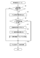
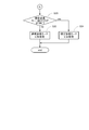
- 6 is a flowchart illustrating a trigger for activating a life management module executed by a control unit.
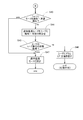
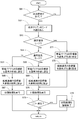
- 6 is a flowchart showing a flow of a life management module executed by a control unit.
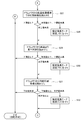
- 6 is a flowchart showing a flow of a drum operation mode determination process executed by a control unit.
- 6 is a flowchart showing a continuation of the processing of FIG. 5.
- 7 is a flowchart showing a continuation of the processing of FIG. 6.
- 7 is a flowchart showing a continuation of the processing of FIG. 6.
- 7 is a flowchart showing a flow of extension mode determination processing executed by a control unit.
- FIG. 10 is a flowchart showing a continuation of the processing of FIG. 9.
- 11 is a flowchart showing a continuation of the processing of FIG. 10.
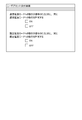
- 6 is a flowchart showing a process executed by a control unit during printing. It is the figure which showed the example of the selection screen displayed on a display, when a control part performs a user selection reception process. It is the figure which showed the example of the selection screen displayed on a display, when a control part performs a user preset reception process.
- FIG. 9 is a schematic diagram of an image forming apparatus according to a modification.
- FIG. 1 is a schematic diagram of the image forming apparatus 1.
- the image forming apparatus 1 is an electrophotographic printer. Examples of the image forming apparatus 1 include a laser printer or an LED printer. As shown in FIG. 1, the image forming apparatus 1 includes a casing 10, four drum cartridges 20, four developing cartridges 30, four light source units 40, a transfer belt 60, a controller 80, and a display 90.
- the casing 10 has a frame 11 and a cover 12.
- the four drum cartridges 20, the four developing cartridges 30, the four light source units 40, the transfer belt 60, and the controller 80 are housed in the casing 10. Further, the display 90 is located on the outer surface of the casing 10.
- the frame 11 has four cartridge holding portions 13. Each cartridge holding portion 13 has an opening 130.
- the cover 12 is rotatable between a closed position shown by a chain double-dashed line in FIG. 1 and an open position shown by a solid line. When the cover 12 is placed in the closed position, the four openings 130 are covered by the cover 12. When the cover 12 is arranged in the open position, the four openings 130 are opened.
- the drum cartridge 20 can be attached/detached to/from the cartridge holding portion 13 with the developing cartridge 30 attached.
- the process cartridge, in which the developing cartridge 30 is mounted on the drum cartridge 20 is attachable/detachable to/from the cartridge holding portion 13.
- the drum cartridge 20 has a photosensitive drum 21.
- the photoconductor drum 21 is a cylindrical member.
- the photoconductor drum 21 is rotatable about the drum shaft.
- the outer peripheral surface of the photosensitive drum 21 is covered with a photosensitive material.
- the drum cartridge 20 has a charger 24.
- the charger 24 extends parallel to the drum shaft of the photoconductor drum 21. Electric power from the image forming apparatus 1 is supplied to the charger 24.
- the drum cartridge 20 has a drum memory 22.
- the drum memory 22 is a recording medium capable of reading and writing information.
- the drum memory 22 is, for example, a flash ROM or an EEPROM.
- the drum memory 22 stores information about the drum cartridge 20. Specifically, the drum memory 22 stores at least one of drum identification information that can identify the individual drum cartridge 20, drum life information, and various information that affects the life of the photoconductor drum 21. I remember.
- the drum identification information is, for example, a serial number.
- the drum life information is at least one of the cumulative number of revolutions of the photosensitive drum 21 and the cumulative number of printed sheets printed using the photosensitive drum 21. In the present embodiment, both of these pieces of information are stored in the drum memory 22 as drum life information.
- the cumulative number of times the discharge abnormality of the charger 24 that charges the photoconductor drum 21 is detected and the identification information does not match the predetermined information.
- the cumulative number of printed sheets using the developing cartridge 30, the number of printed sheets in a high temperature and high humidity environment, the cumulative number of printed sheets in a low temperature and low humidity environment, the cumulative number of paper jam occurrences, and the cumulative number of double-sided printed sheets are stored.
- the developing cartridge 30 can be attached to and detached from the drum cartridge 20.
- the developing cartridge 30 has a housing 39 that can store toner that is a developer.
- the four developing cartridges 30 store toners of different colors (for example, cyan, magenta, yellow, and black colors).
- the developing cartridge 30 of this embodiment has a developing roller 31.
- the developing roller 31 is a cylindrical member.
- the developing roller 31 is rotatable about the developing shaft.
- the developing cartridge 30 has a toner memory 32.
- the toner memory 32 is a recording medium capable of reading and writing information.
- the toner memory 32 is, for example, a flash ROM or an EEPROM.
- the toner memory 32 stores at least one of toner identification information that can identify each developing cartridge 30 and toner life information.
- the toner identification information is, for example, a serial number.
- As the toner life information various known information that can determine whether or not it is time to replace the developing cartridge 30 can be adopted.
- the toner identification information may be, for example, at least one of the cumulative rotation number of the developing roller 31, the cumulative number of printed sheets of the developing roller 31, and the cumulative number of output dots.
- the light source unit 40 faces the surface of the photosensitive drum 21 when the drum cartridge 20 is mounted on the frame 11.
- the light source unit 40 is attached to the frame 11 or the cover 12.
- the light source unit 40 has a plurality of light sources.
- the plurality of light sources are arranged in parallel with the drum axis of the photosensitive drum 21.
- the light source can irradiate the outer peripheral surface of the photoconductor drum 21 with light.
- the light source is, for example, an LED (light emitting diode).
- the light source unit 40 is electrically connected to the control unit 80.
- the control unit 80 causes the plurality of light sources of the light source unit 40 to emit light according to the input image data.
- the light source emits light toward the outer peripheral surface of the photoconductor drum 21.
- the photosensitive material on the outer peripheral surface of the photosensitive drum 21 is exposed according to the image data.
- the light source unit is not limited to the configuration in which the plurality of light sources are arranged in parallel with the drum axis of the photosensitive drum 21. That is, instead of this, the light source unit 40 may be configured to include a light source (laser emission unit), a polygon mirror, a lens, and a reflecting mirror.
- the transfer belt 60 is a belt that comes into contact with the photosensitive drum 21.
- the transfer belt 60 has an annular shape (endless belt).
- the outer peripheral surface of the photosensitive drum 21 contacts the outer surface of the transfer belt 60.
- the drive roller 61 drives the transfer belt 60.
- the controller 80 rotates the transport roller and the drive roller 61.
- the driven roller 62 rotates as the transfer belt 60 moves as the drive roller 61 is driven.
- a combination of the conveying roller, the driving roller 61, and the transfer belt 60 corresponds to the "conveying mechanism" of this embodiment.
- the control unit 80 has a processor 81 such as a CPU and a main body memory 82.
- the main body memory 82 is a recording medium capable of reading and writing information.
- the main body memory 82 is, for example, a flash ROM or an EEPROM. As shown in FIG. 1, in the present embodiment, the main body memory 82 is located on the control unit 80, but instead of this, the main body memory 82 may be located outside the control unit 80.
- the main body memory 82 stores a computer program for controlling the operation of the image forming apparatus 1. Further, the main body memory 82 can store drum identification information, drum life information, various information affecting the life of the photosensitive drum 21, toner identification information, and toner life information.
- the processor 81 executes various processes according to a computer program stored in the main body memory 82. The processor 81 performs a drum replacement necessity determination process, a mode switching process, a toner identification information acquisition process, a latest toner identification information acquisition process, an extended print mode availability determination process, a user selection acceptance process, a print request acceptance process, an extension print command, which will be described later. The processing, the determination processing, and the extension mode determination processing are executed.
- the display 90 displays information regarding the operation of the image forming apparatus 1 and errors (warnings) according to a command from the control unit 80.
- the display 90 is electrically connected to the control unit 80.
- FIG. 2 shows the electrical connection between the control unit 80 and the drum memory 22 and the toner memory 32 when the drum cartridge 20 with the developing cartridge 30 attached is attached to the frame 11. 2 also shows the connection between the control unit 80 and the display 90.
- the drum memory 22 is electrically connected to the control unit 80 via the electrical connector for drum of the frame 11. This allows the processor 81 to read information from the drum memory 22 and write information to the drum memory 22.
- the toner memory 32 is electrically connected to the control unit 80 via the electrical connector for toner of the frame 11. .. This allows the processor 81 to read information from the toner memory 32 and write information to the toner memory 32.
- the toner memory 32 may be electrically connected to the control unit 80 via the drum memory 22.
- the control unit 80 drives a motor (not shown) when executing print processing.
- the photosensitive drum 21 and the developing roller 31 are rotated by the driving force of this motor. Further, the control unit 80 supplies electric power to the charger 24. As a result, the surface of the photoconductor drum 21 is charged. Further, the control unit 80 causes the light source of the light source unit 40 to emit light. The light from the light source is applied to the outer peripheral surface of the photosensitive drum 21. As a result, an electrostatic latent image of an image to be printed is formed on the outer peripheral surface of the photoconductor drum 21.
- the toner in the developing cartridge 30 is supplied onto the electrostatic latent image on the photosensitive drum 21 via the developing roller 31.
- a toner image is formed on the outer peripheral surface of the photosensitive drum 21.
- the printing paper is conveyed between the photoconductor drum 21 and the transfer belt 60.
- the toner image is transferred from the outer peripheral surface of the photoconductor drum 21 to the printing paper.
- the print sheet is conveyed to the fixing unit in the image forming apparatus 1.
- the toner image transferred onto the printing paper is thermally fixed on the printing paper.
- the image is printed on the printing paper.
- the image forming apparatus 1 also has a temperature and humidity sensor (not shown).
- the control unit 80 can determine whether or not the environment is high temperature and high humidity by comparing the detection value output from the temperature and humidity sensor with a preset threshold value. Further, the control unit 80 can determine whether the environment is low temperature and low humidity by comparing the detection value output from the temperature and humidity sensor with another preset threshold value.
- FIG. 3 is a flowchart illustrating a life management module activation process executed by the control unit 80.
- the control unit 80 determines whether the image forming apparatus 1 is powered on (step S1) or whether the cover 12 of the casing 10 is opened/closed (step S2). to continue. Then, when the control unit 80 determines that the power of the image forming apparatus 1 is turned on (step S1: yes) or the cover 12 of the casing 10 has been opened/closed (step S2: yes), the life of the image forming apparatus 1 is reduced.
- the execution of the management module (step S3) is started.
- the control unit 80 performs one of these operations while the image forming apparatus 1 is not powered on (step S1:no) and the cover 12 is not opened/closed (step S2:no). Do not run the life management module until.
- FIG. 4 is a flowchart showing the flow of the life management module executed by the control unit 80.
- the control unit 80 determines whether or not the replacement time arrival flag is ON in the previously performed life management module (step S4). Specifically, the control unit 80 refers to the information stored in the main body memory 82 to make the determination in step S4. When the control unit 80 determines that the life replacement time arrival flag is ON (step S4: yes), the control unit 80 skips the processes of steps S5 to S9 described below and proceeds to the process of step S10. Transition. On the other hand, when the control unit 80 determines that the life replacement time arrival flag is OFF (step S4: no), the control unit 80 subsequently performs the processes of steps S5 to S9.
- the control unit 80 communicates with the drum memory 22 in step S5 to read the drum life information from the drum memory 22 (step S5). More specifically, the control unit 80 of the present embodiment reads the cumulative rotation speed of the photoconductor drum 21 and the cumulative print number of the photoconductor drum 21 from the drum memory 22 of the drum cartridge 20 mounted on the frame 11. ..
- the control unit 80 After acquiring the drum life information, the control unit 80 subsequently determines whether or not the drum cartridge 20 needs to be replaced based on the life information of the drum cartridge 20 (step S6). In other words, the control unit 80 uses the drum life information to determine whether it is time to replace the drum cartridge 20 (drum replacement necessity determination process). In the present embodiment, the control unit 80 controls the drum cartridge 20 when the cumulative number of rotations of the photosensitive drum 21 is equal to or higher than the first threshold value or the cumulative number of printed sheets of the photosensitive drum 21 is equal to or higher than the second threshold value. It is determined that the replacement is necessary (step S6: yes).
- Step S6 no).
- the first threshold is a threshold for determining whether or not the cumulative number of rotations of the photosensitive drum 21 exceeds the upper limit.
- the second threshold is a threshold for determining whether or not the cumulative number of printed sheets using the photoconductor drum 21 exceeds the upper limit.
- step S6 When it is determined that the replacement time of the drum cartridge 20 has been reached (step S6: yes), the control unit 80 subsequently turns on the replacement time arrival flag (step S7). Then, the control unit 80 reads the toner identification information from the toner memory 32 attached to the frame 11 in order to identify the developing cartridge 30 attached to the frame 11 when the replacement time arrives (step S8: toner identification information). (Acquisition process), and this is stored in the drum memory 22 (step S9).
- the control unit 80 stores the toner identification information read from the toner memory 32 in the drum memory 22, and then shifts to a drum operation mode determination process described in detail later (step S10).
- step S6 determines that the replacement time of the drum cartridge 20 has not been reached (step S6: no)
- step S7 to S9 the process of steps S7 to S9 is not performed and the process proceeds to the drum operation mode determination process ( Step S10).
- FIG. 5 is a flowchart showing the flow of the drum operation mode determination processing executed by the control unit 80.
- the control unit 80 determines whether or not the replacement time arrival flag is ON in the previously performed life management module (step S11). Specifically, the control unit 80 refers to the information stored in the main body memory 82 to make the determination in step S11. When the control unit 80 determines that the replacement time arrival flag is OFF (step S11: no), the control unit 80 sets the mode when the printing process is performed to the normal print mode (step S12).
- the normal print mode is a mode in which when a print request is made, a normal charging bias is applied to the charger 24, and the print mechanism is caused to carry print paper at a normal paper feed speed.
- the control unit 80 causes the image forming apparatus 1 to execute the printing process according to the set normal print mode.
- step S11 determines in the determination of step S11 that the replacement timing arrival flag is ON (step S11: yes).
- the control unit 80 determines that the developing cartridge 30 mounted on the drum cartridge 20 is new. The following processing is performed in order to detect whether or not
- control unit 80 communicates with the drum memory 22 and reads the toner identification information from the drum memory 22 (step S13). As a result, the control unit 80 identifies the developing cartridge 30 mounted on the frame 11 at the time when the replacement time is reached. Subsequently, the control unit 80 communicates with the toner memory 32 to read the toner identification information from the toner memory 32 (step S14: latest toner identification information acquisition processing). As a result, the control unit 80 identifies the developing cartridge 30 currently mounted on the frame 11.
- Step S15 extension print mode availability determination processing. In other words, the control unit 80 determines whether the developing cartridge 30 mounted on the frame 11 at the time when the replacement time is reached is replaced with a new developing cartridge 30.
- step S15 when the toner identification information does not match at the time when the replacement time has arrived and at the present time (step S15: no), the drum cartridge 20 which has already been used over its life is further extended and used. Is not desirable.
- the control unit 80 disables the printing process and prompts the user to replace the drum cartridge 20 (step S16). Specifically, the control unit 80 causes the display 90 to display a specific message or image to notify the user that the drum cartridge 20 needs to be replaced.
- step S15 when the toner identification information is the same at the time when the replacement time is reached and at the present time (step S15: yes), the development mounted on the frame 11 when the life of the drum cartridge 20 is reached. In some cases, it is better to permit the printing process as long as the cartridge 30 can be used continuously. In this case, the control unit 80 proceeds to extension mode determination processing (step S17) in order to determine (select) a suitable mode for extending the life of the drum cartridge 20 and performing printing processing.
- extension mode determination process executed by the control unit 80 will be described with reference to FIGS. 9 to 11.
- 9 to 11 are flowcharts showing the flow of the extension mode determination process executed by the control unit 80.
- the control unit 80 reads, from the drum memory 22, the cumulative number of times the discharge abnormality of the charger 24 that charges the photosensitive drum 21 is detected (step S21).
- the control unit 80 disables the print process (print disable mode: print disable mode determination process).
- the print processing mode is not set to any extension mode. This is because it is not preferable to use the drum cartridge 20 in which abnormal discharge frequently occurs over its life.
- the control unit 80 turns on the limited extension mode setting flag (step S22).
- step S21 when the cumulative number of discharge abnormalities read in step S21 is less than the predetermined value, the control unit 80 proceeds to step S23 in order to evaluate the magnitude of other parameters that affect the life of the photosensitive drum 21. Transition.
- This step S21 and the process of evaluating the magnitude of the parameter read at this time correspond to the "determination process" of this embodiment.
- the control unit 80 reads from the drum memory 22 the cumulative number of printed sheets using the developing cartridge 30 whose identification information does not match the predetermined information (step S23).
- the control unit 80 disables the print processing (print disable mode: print disable mode determination processing).
- the print processing mode is not set to any extension mode. This is because, for example, if the drum cartridge 20 whose manufacturer is unknown is used in the printing process, damage to the photosensitive drum 21 cannot be predicted.
- the control unit 80 turns on the limited extension mode setting flag (step S24).
- step S23 when the cumulative number of printed sheets read in step S23 is less than the predetermined value, the control unit 80 proceeds to step S25 in order to evaluate the magnitude of other parameters that affect the life of the photosensitive drum 21. ..
- This step S23 and the process of evaluating the magnitude of the parameter read at this time correspond to the "determination process" of this embodiment.
- the control unit 80 reads the cumulative number of printed sheets in the hot and humid environment from the drum memory 22 (step S25).
- the control unit 80 disables the print processing (print disable mode: print disable mode determination processing).
- the print processing mode is not set to any extension mode. This is because if the drum cartridge 20 is used for a printing process in a high temperature and high humidity environment, the photoconductor drum 21 may be deteriorated.
- the control unit 80 turns on the limited extension mode setting flag (step S26).
- control unit 80 when the cumulative number of printed sheets read in step S25 is less than the predetermined value, the control unit 80 also evaluates the magnitudes of other parameters that affect the life of the photosensitive drum 21, in step 27 (see FIG. 10). See). This step S25 and the process of evaluating the size of the parameter read at this time correspond to the "determination process" of this embodiment.
- the control unit 80 reads the cumulative number of printed sheets in the low temperature and low humidity environment from the drum memory 22 (step S27).
- the control unit 80 disables the print processing (print disable mode: print disable mode determination processing).
- the print processing mode is not set to any extension mode. This is because if the drum cartridge 20 is used for a printing process in a low temperature and low humidity environment, the photoconductor drum 21 may be deteriorated.
- the control unit 80 turns on the limited extension mode setting flag (step S28).
- step S27 when the cumulative number of printed sheets read in step S27 is less than the predetermined value, the control unit 80 proceeds to step S29 in order to evaluate the magnitude of other parameters that affect the life of the photosensitive drum 21. ..
- This step S27 and the process of evaluating the magnitude of the parameter read at this time correspond to the "determination process" of this embodiment.
- the control unit 80 reads the cumulative number of times of paper jam occurrence from the drum memory 22 (step S29).
- the control unit 80 disables the print processing when the cumulative number of paper jam occurrences read in step S29 is equal to or more than the upper limit value (print disable mode: print disable mode determination process).
- the print processing mode is not set to any extension mode. This is because if the paper jam frequently occurs, the deterioration of the photoconductor drum 21 may progress.
- the control unit 80 turns on the limited extension mode setting flag (step S30).
- step S29 when the cumulative number of paper jam occurrences read in step S29 is less than the predetermined value, the control unit 80 proceeds to step S31 in order to evaluate the magnitude of other parameters that affect the life of the photosensitive drum 21. And transition.
- This step S29 and the process of evaluating the size of the parameter read at this time correspond to the "determination process" of this embodiment.
- the control unit 80 reads the cumulative number of double-sided prints from the drum memory 22 (step S31).
- the control unit 80 disables the print process (print disable mode: print disable mode determination process).
- print disable mode print disable mode determination process
- the print processing mode is not set to any extension mode. This is because, if the number of sheets printed on one side is large, the amount of paper dust generated is large and the deterioration of the photosensitive drum 21 may easily proceed.
- the control unit 80 turns on the limited extension mode setting flag when the cumulative number of double-sided prints read in step S31 is equal to or more than the lower limit value and less than the predetermined value (step S32).
- control unit 80 determines the extension mode by combining the results of evaluation of a plurality of parameters so far (selection). , And the subsequent steps S33 to S35 (see FIG. 11) are performed.
- step S33 the control unit 80 determines whether or not the limited extension mode setting flag is ON as a result of performing a plurality of determination processes so far (step S33).
- step S33: yes the control unit 80 temporarily sets the print processing mode to the limited extension mode (step S34). Specifically, the control unit 80 writes, in the main body memory 82, information indicating that the print processing mode is temporarily set to the limited extension mode.
- the limited extension mode when a print request is made, a charging bias lower than the normal charging bias is applied to the charger 24, and the feeding mechanism is operated at a feeding speed slower than the ordinary feeding speed. In this mode, the printing paper is conveyed.
- step S35 the control unit 80 provisionally sets the print processing mode to the normal extension mode (step S35). Specifically, the control unit 80 writes, in the main body memory 82, information indicating that the print processing mode is temporarily set to the normal extension mode. Note that in the normal extension mode, when a print request is made, the same charging bias as in the normal print mode is applied to the charger 24, and printing paper is fed to the transport mechanism at the same paper feed speed as in the normal print mode. This is the mode of transporting.
- FIG. 6 is a flowchart showing the continuation of the processing of FIG. 7 and 8 are flowcharts showing the continuation of the process of FIG. 6, respectively.
- the control unit 80 determines whether or not the print processing mode is provisionally set to the normal extension mode (step S41). When the print processing mode is temporarily set to the normal extension mode (step S41: yes), the control unit 80 proceeds to a series of processing shown in FIG. On the other hand, the control unit 80 does not provisionally set the print processing mode to the normal extension mode (step S41: no). Subsequently, it is determined whether or not the print processing mode is provisionally set to the limited extension mode (step S42). When the print processing mode is provisionally set to the limited extension mode (step S42: yes), the control unit 80 then proceeds to the series of processing shown in FIG.
- step S42 when the print processing mode is not temporarily set to the limited extension mode (step S42: no), the control unit 80 disables the print processing and prompts the user to replace the drum cartridge 20 (step S16). .. That is, in this case, the requirement for extending the life of the drum cartridge 20 is not satisfied. Therefore, the user is notified that the drum cartridge 20 needs to be replaced without extending the life.
- step S43 the control unit 80 notifies the user that the normal extension mode is already in effect and determines whether or not consent has been obtained. Specifically, by referring to the information stored in the main body memory 82, the control unit 80 performed the operation to permit the mode shift by the user in step S45 executed in the past (step S45: yes). It is determined whether or not.
- step S43: no the control unit 80 notifies the user of the shift to the normal extension mode, and inquires about the possibility. Is performed (step S44).
- control unit 80 causes the display 90 to display a specific display screen as shown in FIG. 13, thereby notifying the user that the normal extension mode is about to be switched, and at the same time, notifying the user of the possibility.
- a selection is made (step S45: user selection acceptance process).
- step S45: yes When the user's consent is obtained as a result of the processing of steps S44 to S45 (step S45: yes), the control unit 80 sets the print processing mode to the normal extension mode (step S47). Specifically, the control unit 80 writes information indicating the normal extension mode in the main body memory 82.
- step S45: no the control unit 80 prohibits printing and prompts the user to replace the drum cartridge 20 (step S46). Specifically, by displaying a specific display screen on the display 90, the user is notified that the drum cartridge 20 needs to be replaced.
- control unit 80 when the control unit 80 has executed the previous life management module and has already notified the user of the shift to the normal extension mode and has obtained consent (step S43: yes), the control unit 80 notifies the user again.
- the print processing mode is set to the normal extension mode without making an inquiry (step S47).
- the control unit 80 When the print processing mode is temporarily set to the limited print mode, the control unit 80 notifies the user that the limited extension mode has already been entered and determines whether or not consent has been obtained (step S48). Specifically, the control unit 80 refers to the information stored in the main body memory 82 to perform the operation for permitting the mode shift by the user in step S50 executed in the past (step S50: yes). It is determined whether or not. When the control unit 80 has not yet notified the user of the shift to the limited extension mode (step S48: no), the control unit 80 notifies the user of the shift to the limited extension mode and inquires whether or not the shift is possible. Is performed (step S49).
- control unit 80 causes the display 90 to display a specific display screen similar to that shown in FIG. 13, thereby notifying the user that the limited extension mode is about to be switched and selecting the permission/prohibition to the user. (Step S50: user selection acceptance process).
- step S50 When the user's consent is obtained as a result of the processing in steps S49 to S50 (step S50: yes), the control unit 80 sets the print processing mode to the limited extension mode (step S53). Specifically, the control unit 80 writes information indicating the limited extension mode in the main body memory 82.
- step S50: no the control unit 80 prohibits printing and prompts the user to replace the drum cartridge 20 (step S52). Specifically, by displaying a specific display screen on the display 90, the user is notified that the drum cartridge 20 needs to be replaced.
- control unit 80 informs the user of the fact that the user intends to shift to the limited extension mode and obtains consent (step S49: yes), and notifies the user again.
- the print processing mode is set to the limited extension mode without making an inquiry (step S53).
- FIG. 12 is a flowchart showing the flow of the printing process executed by the control unit 80.
- control unit 80 determines whether or not there is a print request (step S61: print request acceptance process). When there is a print request (step S61: yes), the control unit 80 reads the mode set as the print processing mode from the main body memory 82 (step S62).
- step S62 When the print processing mode read in step S62 is neither the limited extension mode (step S63:no) nor the normal extension mode (step S64:no), the control unit 80 controls the steps S65 to S67.
- the control unit 80 sets the target value of the charging bias applied to the charger 24 to the normal state, and supplies power to the charger 24 (step S65). Further, the control unit 80 sets the target value of the paper feed speed for sending the printing paper to the transport mechanism to the normal state, and operates the transport mechanism (step S66). In such a state, the control unit 80 causes the image forming apparatus 1 to execute the print processing (step S67).
- step S64 the control unit 80 executes the print processing in the normal extension mode by the processing of steps S68 to S70. Specifically, the control unit 80 sets the target value of the charging bias applied to the charger 24 to the normal state, and supplies power to the charger 24 (step S68). Further, the control unit 80 sets the target value of the paper feeding speed for sending the printing paper to the transport mechanism to the normal state, and operates the transport mechanism (step S69). In such a state, the control unit 80 causes the image forming apparatus 1 to execute print processing (step S70: extended print command processing).
- step S73 when a predetermined error such as a discharge error occurs during the execution of the printing process in step S70 (step S73: yes), the control unit 80 forcibly terminates the printing process (step S74). ..
- a predetermined error such as a discharge error occurs during the execution of the printing process in step S70
- step S74 the control unit 80 forcibly terminates the printing process.
- step S63 the control unit 80 executes the print processing in the limited extension mode by the processing of steps S71, S72, and S70.
- the control unit 80 sets the target value of the charging bias applied to the charger 24 to a value lower than usual (in the present embodiment, half the normal value), and supplies power to the charger 24 ( Step S71).
- the control unit 80 sets the target value of the paper feed speed for sending the printing paper to the transport mechanism to be slower than usual (in this embodiment, half the normal speed) to operate the transport mechanism. (Step S72). In such a state, the control unit 80 causes the image forming apparatus 1 to execute the print processing (step S70).
- step S73 when a predetermined error such as a discharge error occurs during the execution of the printing process in step S70 (step S73: yes), the control unit 80 forcibly terminates the printing process (step S74). ..
- a predetermined error such as a discharge error occurs during the execution of the printing process in step S70 (step S73: yes)
- the control unit 80 forcibly terminates the printing process (step S74). ..
- a predetermined error is detected while the life of the drum cartridge 20 is extended and the printing process is being executed in the limited extension mode, printing is immediately switched to printing disabled. As a result, safety can be improved.
- the image forming apparatus 1 of this embodiment includes the frame 11, the drum cartridge 20, the developing cartridge 30, and the control unit 80.
- the control unit 80 can execute the drum replacement necessity determination process and the mode switching process for switching between the normal print mode and the extended print mode.
- the replacement work of the drum cartridge 20 and the development cartridge 30 can be performed at the same time, and the replacement drum cartridge 20 and the development cartridge 30 can be ordered at the same time, which is troublesome and burdensome for the user.
- Transportation costs are reduced. Further, since the drum cartridge 20 and the developing cartridge 30 can be ordered at the same time, the transportation cost can be reduced.
- the image forming apparatus 1 of the present embodiment can execute the toner identification information acquisition process, the latest toner identification information acquisition process, and the extended print mode availability determination process. As a result, by using the toner identification information read from the toner memory 32, it is possible to easily know whether the same developing cartridge 30 is used before and after the end of the life of the drum cartridge 20.
- the extended print mode availability determination process performed by the control unit 80 when the toner identification information of the developing cartridge 30 mounted on the frame 11 is not changed in the state where the drum cartridge 20 needs to be replaced, the extended print mode is determined. Allow setting to mode.
- the extended print mode availability determination process performed by the control unit 80 when the toner identification information of the developing cartridge 30 mounted on the frame 11 is changed while the drum cartridge 20 needs to be replaced, Do not allow setting to extended print mode.
- the drum cartridge 20 that has already been used beyond the end of its life should be extended and used again. Disables printing from the perspective of being undesirable. Therefore, it is possible to prevent the quality of printing from being deteriorated due to the drum cartridge 20 being used far beyond its life.
- control unit 80 can execute a user selection reception process. This allows the user to operate the image forming apparatus 1 according to the intention of the user by allowing the user to select whether or not to permit the transition to the extended print mode.
- the extended print mode of this embodiment includes a normal extended mode and a limited extended mode.
- the control unit 80 can execute a determination process for evaluating the size of a parameter that affects the life of the photosensitive drum 21.
- the control unit 80 sets the printing process mode to the normal extension mode.
- the control unit 80 sets the print processing mode to the limited extension mode.
- the first condition and the second condition are the number of times the discharge abnormality of the charger 24 that charges the photosensitive drum 21 is detected, and the number of sheets printed using the developing cartridge 30 whose identification information does not match the predetermined information. It is a condition relating to at least one of the number of printed sheets in a high temperature and high humidity environment, the number of printed sheets in a low temperature and low humidity environment, the number of paper jam occurrences, and the number of double-sided printed sheets. As a result, it is possible to set the appropriate extension mode and perform printing in accordance with the size of the parameter that affects the life of the drum cartridge 20.
- the present application discloses a program for causing the control unit 80 mounted in the image forming apparatus 1 or an external control unit to execute the drum replacement necessity determination process and the mode switching process.
- an image forming method capable of causing the image forming apparatus 1 to execute a printing process according to a set mode, and a) replacing the drum cartridge 20 based on life information of the drum cartridge 20.
- An image forming method is disclosed in which it is determined whether or not it is necessary and b) the normal print mode and the extended print mode are switched according to the condition.
- the control unit 80 causes the display 90 to display a selection screen as shown in FIG. 14 in the user preset reception process. In the example of FIG. 14, when the user selects either “ON” or “OFF” in the check box format on the selection screen, whether or not to permit the transition to the extension mode is uniformly set.
- the control unit 80 determines whether the toner identification information acquired in the toner identification information acquisition process and the toner identification information read in the latest toner identification information acquisition process match. It was performed (extended print mode availability determination processing). However, instead of this, the control unit 80 may perform the following processing. That is, the control unit 80 may sequentially store the identification information of the developing cartridges 30 mounted on the frame 11 in the main body memory 82, instead of performing the toner identification information acquisition process. In that case, the control unit 80 refers to the history of the toner identification information stored in the main body memory 82 in the extended print mode availability determination process, and compares this with the toner identification information read in the latest toner identification information acquisition process. It may be determined whether or not they match.
- the control unit 80 may perform the following processing instead of determining whether the developing cartridge 30 has been replaced with a new one based on the read toner identification information. That is, the control unit 80 detects that the developing cartridge 30 is "new" by a mechanical method, and stores the cumulative number of times the new cartridge is detected in the memory. Then, after the replacement time arrival flag of the drum cartridge 20 is turned on, the life of the drum cartridge 20 can be extended and printing processing can be performed while the cumulative number of times a new article is detected has not increased. On the other hand, if the number of times a new article has been detected increases after the replacement time arrival flag of the drum cartridge 20 is turned on, printing is disabled.
- control unit 80 may perform a process of causing the user to set the upper limit value of the number of printed sheets in the extended print mode.
- control unit 80 counts only the cumulative number of paper jam occurrences at positions where the life of the photoconductor drum 21 is adversely affected to determine whether the first condition or the second condition is satisfied. It may be determined whether or not.
- the processing, the determination processing, and the extension mode determination processing are performed by the processor 81 of the main body of the image forming apparatus 1, the present invention is not limited to this. That is, for example, the drum cartridge 20 may include a drum side processor, and the drum side processor may perform the above-described various processes. Alternatively, a driver of a computer outside the image forming apparatus 1 or a CPU mounted on a wireless communication terminal such as a smartphone may perform the above various processes.
- the pair of cartridges of each color is individually mounted on the frame 11 in a state where the drum cartridge 20 and the developing cartridge 30 form a pair.
- the developing cartridges 30 of the respective colors may be mounted on the common drum cartridge 20. In that case, when the replacement time comes, the drum cartridges 20 having the photosensitive drums 21 of all colors are collectively replaced with new ones.
- the control unit performs the following processing.
- the print processing mode is set to the limited extension mode.
- the example disclosed in this embodiment is a developing cartridge having a developing roller.
- a developing cartridge having no developing roller may be used.
- the developing roller may be included in the drum cartridge.
- one drum cartridge 20 is provided for one developing cartridge 30.
- a drawer (drum cartridge) having four photosensitive drums 21 may have one drum memory 22.
- the drawer can mount four developing cartridges 30.
- the drawer can mount the developing cartridge 30 on each of the four photoconductor drums 21.
- the drum memory 22 stores the above-mentioned information about the drum cartridge for each of the four photosensitive drums 21.
- the configuration of the image forming apparatus and the details of the processing may be appropriately changed without departing from the gist of the present application.
- the number of determination processes may be more or less than those described above.
- the respective elements appearing in the above-described embodiments and modified examples may be appropriately combined as long as no contradiction occurs.
Landscapes
- Engineering & Computer Science (AREA)
- Physics & Mathematics (AREA)
- General Physics & Mathematics (AREA)
- General Engineering & Computer Science (AREA)
- Theoretical Computer Science (AREA)
- Microelectronics & Electronic Packaging (AREA)
- Control Or Security For Electrophotography (AREA)
- Electrophotography Configuration And Component (AREA)
- Accessory Devices And Overall Control Thereof (AREA)
Abstract
消耗品であるカートリッジの交換に際しての、ユーザの手間と負担を軽減することができる技術を提供する。制御部80は、ドラム交換要否判定処理と、モード切替処理とを実行可能である。ドラム交換要否判定処理は、ドラムカートリッジ20の寿命情報に基づいてドラムカートリッジ20の交換が必要か否かを判定する。モード切替処理は、通常印刷モードと、延長印刷モードとを切り替える。通常印刷モードは、ドラムカートリッジ20の交換が不要と判定された場合、画像形成装置1に印刷処理を実行させることが可能である。延長印刷モードは、ドラムカートリッジ20の交換が必要な状態において、フレーム11に装着された現像カートリッジ30が別の現像カートリッジ30に取り替えられていないことを条件として、画像形成装置1に印刷処理を実行させることが可能である。
Description
本開示は、画像形成装置、画像形成プログラム、および画像形成方法に関する。
従来、LEDプリンタ等の電子写真方式の画像形成装置が知られている。この種の画像形成装置は、装置本体と、装置本体に対して着脱可能なドラムカートリッジおよび現像カートリッジとを有する。装置本体と、ドラムカートリッジおよび現像カートリッジとを有する従来の画像形成装置については、例えば、特許文献1に記載されている。
特許文献1に記載の画像形成装置では、現像カートリッジがドラムカートリッジに装着された状態で、装置本体に、現像カートリッジとドラムカートリッジとが着脱可能に装着される。現像カートリッジおよびドラムカートリッジは、それぞれ、交換可能な消耗品である。また、特許文献1に記載の画像形成装置は、寿命判定手段と、報知部とを有する。寿命判定手段は、ドラムカートリッジの寿命を判定する。報知部は、寿命判定手段によってドラムカートリッジが寿命であると判定された場合に、ドラムカートリッジが寿命であることを示すメッセージを報知する。その結果、ユーザは、ドラムカートリッジの交換を認識することができる。
また、特許文献1に記載の画像形成装置は、トナー消費量を推定するトナー消費量推定手段を備える。
しかしながら、特許文献1に記載のような画像形成装置では、現像カートリッジが寿命であることが報知されてから、短時間の間に、次はドラムカートリッジが寿命であることが報知される場合がある。この場合、現像カートリッジとドラムカートリッジのそれぞれの交換タイミングが異なるため、例えば、新品の現像カートリッジと新品のドラムカートリッジとの発注を頻繁に行ったりする必要が生じ、ユーザに手間や負担が掛かってしまう。また、各カートリッジを個別に発注したのでは、輸送コストが増大する。
本開示は、消耗品であるカートリッジの交換に際しての、ユーザの手間と負担を軽減することができる技術を提供することを目的とする。
本願の第1の観点によれば、以下の構成の画像形成装置が提供される。即ち、この画像形成装置は、フレームと、ドラムカートリッジと、現像カートリッジと、制御部とを備える。前記ドラムカートリッジは、前記フレームに対して装着されるドラムカートリッジであって、感光体ドラムを有する。前記現像カートリッジは、前記フレームに対して装着される現像カートリッジであって、トナーを収容可能な筐体を有する。前記制御部は、前記画像形成装置に印刷処理を実行させる。前記制御部は、ドラム交換要否判定処理と、モード切替処理とを実行可能である。前記ドラム交換要否判定処理は、前記ドラムカートリッジの寿命情報に基づいて前記ドラムカートリッジの交換が必要か否かを判定する。前記モード切替処理は、通常印刷モードと、延長印刷モードとを切り替える。前記通常印刷モードは、前記ドラムカートリッジの交換が不要と判定された場合、前記画像形成装置に印刷処理を実行させることが可能である。前記延長印刷モードは、前記ドラムカートリッジの交換が必要な状態において、前記フレームに装着された前記現像カートリッジが別の現像カートリッジに取り替えられていないことを条件として、前記画像形成装置に印刷処理を実行させることが可能である。
本願の第2の観点では、第1の観点の画像形成装置において、前記制御部は、前記画像形成装置の本体部のプロセッサである。
本願の第3の観点では、第1の観点または第2の観点の画像形成装置において、前記制御部は、さらに、前記ドラムカートリッジの交換が必要となったと判定された場合に、前記フレームに装着された前記現像カートリッジの識別情報であるトナー識別情報を取得し記憶するトナー識別情報取得処理を実行可能である。また、前記モード切替処理では、前記ドラムカートリッジの交換が必要な状態において、前記フレームに装着された前記現像カートリッジの前記トナー識別情報に変更がないと前記制御部が判断した場合に、前記延長印刷モードに切替え可能である。
本願の第4の観点では、第3の観点の画像形成装置において、前記現像カートリッジは、前記トナー識別情報が記憶されたトナーメモリを有する。前記制御部は、前記トナーメモリから前記トナー識別情報を取得可能である。
本願の第5の観点では、第4の観点の画像形成装置において、前記制御部は、前記トナー識別情報取得処理において、前記ドラムカートリッジの交換が必要となったと判定された場合に、前記フレームに装着された前記現像カートリッジの前記トナー識別情報を前記トナーメモリから読み出す。前記制御部は、さらに、最新トナー識別情報取得処理と、延長印刷モード可否判定処理とを実行する。前記トナー識別情報取得処理は、前記トナー識別情報取得処理よりも後に、前記フレームに装着されている前記現像カートリッジの前記トナー識別情報を前記トナーメモリから読み出す。前記延長印刷モード可否判定処理は、前記トナー識別情報取得処理において読み出された前記トナー識別情報と、前記最新トナー識別情報取得処理において読み出された前記トナー識別情報とが一致する場合に、前記延長印刷モードへの設定を許可する。
本願の第6の観点では、第3の観点または第4の観点の画像形成装置において、前記制御部は、延長印刷モード可否判定処理を実行する。前記延長印刷モード可否判定処理では、前記ドラムカートリッジの交換が必要となった状態において、前記フレームに装着された前記現像カートリッジの前記トナー識別情報に変更がない場合に、前記延長印刷モードへの設定を許可する一方、前記ドラムカートリッジの交換が必要となった状態において、前記フレームに装着された前記現像カートリッジの前記トナー識別情報に変更があった場合に、前記延長印刷モードへの設定を許可しない延長印刷モード可否判定処理を実行する。
本願の第7の観点では、第6の観点に係る画像形成装置において、前記制御部は、さらにユーザ選択受付処理を実行する。前記ユーザ選択受付処理では、前記ドラムカートリッジの交換が必要となった状態において、前記フレームに装着された前記現像カートリッジの前記トナー識別情報に変更がない場合に、前記延長印刷モードへの移行を許可するか否かをユーザに問い合わせる。
本願の第8の観点では、第6の観点に係る画像形成装置において、前記制御部は、さらにユーザプリセット受付処理を実行する。前記ユーザプリセット受付処理では、前記ドラムカートリッジの交換が必要となった状態において、前記フレームに装着された前記現像カートリッジの前記トナー識別情報に変更がない場合に、一律に、前記延長印刷モードへの移行を許可するか否かを、ユーザに予め設定させる。
本願の第9の観点では、第1の観点から第8の観点のいずれか1つの画像形成装置において、印刷用紙を搬送する搬送機構をさらに備える。また、前記ドラムカートリッジは、前記感光体ドラムの表面を帯電させる帯電器を有する。前記制御部は、さらに、印刷要求受付処理と、延長印刷指令処理とを実行可能である。前記印刷要求受付処理は、印刷要求を受け付ける。前記延長印刷指令処理は、前記延長印刷モードに設定された状態において、印刷要求が受け付けられた場合に、前記帯電器に前記通常印刷モードと同一の帯電バイアスを作用させ、かつ、前記搬送機構に前記通常印刷モードと同一の給紙速度で印刷用紙を搬送させて、前記画像形成装置に印刷処理を実行させる。
本願の第10の観点では、第1の観点から第8の観点のいずれか1つの画像形成装置において、前記延長印刷モードには、通常延長モードと、限定延長モードとが含まれる。前記通常延長モードでは、前記通常印刷モードと同一の帯電バイアスで、かつ、前記通常印刷モードと同一の給紙速度で、前記画像形成装置に印刷処理を実行させることが可能である。前記限定延長モードでは、前記通常印刷モードよりも低い帯電バイアスで、かつ、前記通常印刷モードよりも遅い給紙速度で、前記画像形成装置に印刷処理を実行させることが可能である。
本願の第11の観点では、第10の観点の画像形成装置において、前記制御部は、さらに、判断処理と、延長モード判定処理とを実行可能である。前記判断処理は、前記感光体ドラムの寿命に影響するパラメータの大きさを評価する。前記延長モード判定処理は、前記判断処理により第1条件を満たすと判断された場合には、前記延長印刷モードを前記通常延長モードとし、前記判断処理により前記第1条件とは異なる第2条件を満たすと判断された場合には、前記延長印刷モードを前記限定延長モードとする。
本願の第12の観点では、第11の観点の画像形成装置において、前記第1条件および前記第2条件は、それぞれ、前記感光体ドラムを帯電させる帯電器の放電異常を検知した回数、識別情報が所定の情報と一致しない前記現像カートリッジを用いての印刷枚数、高温多湿環境での印刷枚数、低温低湿環境での印刷枚数、紙詰まり発生回数、および両面印刷枚数の少なくとも何れかに関する条件である。
本願の第13の観点では、第12の観点の画像形成装置において、前記ドラムカートリッジは、前記ドラムカートリッジを識別可能なドラム識別情報が記憶されたドラムメモリを有する。前記ドラムメモリは、前記ドラム識別情報に対応付けて、前記帯電器の放電異常を検知した回数、識別情報が所定の情報と一致しない前記現像カートリッジを用いての印刷枚数、高温多湿環境での印刷枚数、低温低湿環境での印刷枚数、紙詰まり発生回数、および両面印刷枚数の少なくともいずれかを記憶可能である。
本願の第14の観点では、第10の観点の画像形成装置において、前記制御部は、さらに、判断処理と、印刷不可モード判定処理とを実行可能である。前記判断処理は、前記感光体ドラムの寿命に影響するパラメータの大きさを評価する。前記印刷不可モード判定処理は、前記判断処理により第1条件を満たさないと判断され、かつ、前記第1条件とは異なる第2条件を満たさないと判断された場合には、前記画像形成装置による印刷を不可とする印刷不可モードとする。
本願の第15の観点によれば、第1から第14の観点のいずれか1つの画像形成装置において、前記ドラムカートリッジは、前記感光体ドラムの累積回転数、または、前記感光体ドラムを使って印刷を行った累積印刷枚数の少なくともいずれかを表すドラム寿命情報を記憶し、前記制御部は、前記ドラムメモリに記憶された前記累積回転数、または、前記累積印刷枚数に基づいて、前記累積回転数、または、前記累積印刷枚数が所定の閾値以上である場合に、前記ドラムカートリッジの交換が必要な状態であると判定する。
本願の第16の観点によれば、フレームと、ドラムカートリッジと、現像カートリッジとを備える画像形成装置に、設定されたモードに従って印刷処理を実行させることが可能な画像形成プログラムが提供される。前記ドラムカートリッジは、前記フレームに対して装着されるドラムカートリッジであって、感光体ドラムを有する。前記現像カートリッジは、前記フレームに対して装着される現像カートリッジであって、トナーを収容可能な筐体を有する。前記画像形成プログラムは、前記画像形成装置に搭載される制御部または外部の制御部に、次のa)およびb)を実行させる。a)では、前記ドラムカートリッジの寿命情報に基づいて前記ドラムカートリッジの交換が必要か否かを判定するドラム交換要否判定処理を実行させる。b)では、通常印刷モードと、延長印刷モードとを切り替えるモード切替処理を実行させる。前記通常印刷モードでは、前記ドラムカートリッジの交換が不要と判定された場合、前記画像形成装置に印刷処理を実行させることが可能である。前記延長印刷モードでは、前記ドラムカートリッジの交換が必要な状態において、前記フレームに装着された前記現像カートリッジが別の現像カートリッジに取り替えられていないことを条件として、前記画像形成装置に印刷処理を実行させることが可能である。
本願の第17の観点によれば、フレームと、ドラムカートリッジと、現像カートリッジとを備える画像形成装置に、設定されたモードに従って印刷処理を実行させることが可能な画像形成方法が提供される。前記ドラムカートリッジは、前記フレームに対して装着されるドラムカートリッジであって、感光体ドラムを有する。前記現像カートリッジは、前記フレームに対して装着される現像カートリッジであって、トナーを収容可能な筐体を有する。前記画像形成方法は、次のa)およびb)の工程を有する。a)では、前記ドラムカートリッジの寿命情報に基づいて前記ドラムカートリッジの交換が必要か否かを判定する。b)では、通常印刷モードと、延長印刷モードとを切り替える。前記通常印刷モードでは、前記ドラムカートリッジの交換が不要と判定された場合、前記画像形成装置に印刷処理を実行させることが可能である。前記延長印刷モードでは、前記ドラムカートリッジの交換が必要な状態において、前記フレームに装着された前記現像カートリッジが別の現像カートリッジに取り替えられていないことを条件として、前記画像形成装置に印刷処理を実行させることが可能である。
本願の第1の観点から第16の観点によれば、消耗品であるカートリッジの交換に際しての、ユーザの手間と負担を軽減することができる技術が提供される。
本願の第1の観点によれば、ドラムカートリッジの交換が必要となった後も、ドラムカートリッジの寿命到達時点でフレームに装着していた現像カートリッジを使い続ける限りにおいて、ドラムカートリッジを交換することなく印刷処理を継続して行うことが可能となる。別の言い方をすれば、ドラムカートリッジの寿命到達の前後で同じ現像カートリッジを使用している間は、ドラムカートリッジの寿命を延長して印刷処理を続けることが可能となる。その結果、ドラムカートリッジおよび現像カートリッジの交換作業を同時期に行ったり、交換用のドラムカートリッジおよび現像カートリッジの発注を同時期に行ったりすることが可能となり、ユーザの手間と負担や、輸送コストが軽減される。
本願の第5の観点によれば、トナーメモリから読み出されるトナー識別情報を利用して、ドラムカートリッジの寿命到達の前後で同じ現像カートリッジが使用されているか否かを容易に知ることができる。
本願の第6の観点によれば、ドラムカートリッジが寿命に到達した後に、フレームに装着された現像カートリッジが交換された場合には、既に寿命を超えて使用しているドラムカートリッジをさらに延長して使用することは望ましくないという観点から、印刷を不能にする。よって、ドラムカートリッジが寿命をはるかに超えて使用されて印刷の品質が落ちてしまうことを防止できる。
本願の第7の観点によれば、ユーザに、延長印刷モードへの移行を許可するか否かを選択させることにより、ユーザの意志に応じて画像形成装置を運用することが可能となる。
ここで、延長印刷モード可否判定処理が実行される度に、ユーザに延長印刷モードへの移行を許可するか否かを選択させると、ユーザが操作を煩わしく感じる虞がある。この点、本願の第8の観点によれば、前もって、延長印刷モードへの移行を許可するか否かを一律に定めることができ、ユーザの手間や負担が軽減される。
本願の第11の観点によれば、状況に応じて、通常延長モードと限定延長モードとを切り替えることができる。よって、ドラムカートリッジが寿命を超えて使用されて印刷の品質が落ちてしまうことを抑制できる。
本願の第12の観点によれば、ドラムカートリッジの寿命に影響するパラメータの大きさに応じて、適切な方の延長モードに設定して印刷を行うことができる。
本願の第14の観点によれば、判断処理の結果に状況に応じて、印刷を不可とすることが可能である。よって、印刷処理に好ましくない状況のときに寿命を超えて印刷処理が行われて印刷の品質が落ちてしまうことを抑制できる。
以下、本開示の実施形態について、添付図面を参照しつつ説明する。
<1.実施形態>
<1-1.画像形成装置の構成について>
図1は、画像形成装置1の概略図である。画像形成装置1は、電子写真方式のプリンタである。画像形成装置1の例としては、レーザープリンタ、または、LEDプリンタが挙げられる。図1に示すように、画像形成装置1は、ケーシング10、4つのドラムカートリッジ20、4つの現像カートリッジ30、4つの光源ユニット40、転写ベルト60、制御部80、およびディスプレイ90を備えている。
<1-1.画像形成装置の構成について>
図1は、画像形成装置1の概略図である。画像形成装置1は、電子写真方式のプリンタである。画像形成装置1の例としては、レーザープリンタ、または、LEDプリンタが挙げられる。図1に示すように、画像形成装置1は、ケーシング10、4つのドラムカートリッジ20、4つの現像カートリッジ30、4つの光源ユニット40、転写ベルト60、制御部80、およびディスプレイ90を備えている。
ケーシング10は、フレーム11とカバー12とを有する。4つのドラムカートリッジ20、4つの現像カートリッジ30、4つの光源ユニット40、転写ベルト60、および制御部80は、ケーシング10に収容される。また、ディスプレイ90は、ケーシング10の外表面に位置する。フレーム11は、4つのカートリッジ保持部13を有する。各カートリッジ保持部13は、開口130を有する。カバー12は、図1中に二点鎖線で示した閉鎖位置と、実線で示した開放位置との間で、回動可能である。カバー12が閉鎖位置に配置されたときには、4つの開口130が、カバー12により覆われる。カバー12が開放位置に配置されたときには、4つの開口130が開放される。
ドラムカートリッジ20は、現像カートリッジ30を装着した状態で、カートリッジ保持部13に着脱可能である。別の言い方をすれば、ドラムカートリッジ20に現像カートリッジ30が装着されたものであるプロセスカートリッジは、カートリッジ保持部13に着脱可能である。
ドラムカートリッジ20は、感光体ドラム21を有する。感光体ドラム21は、円筒状の部材である。感光体ドラム21は、ドラム軸について回転可能である。感光体ドラム21の外周面は、感光材料に覆われている。また、ドラムカートリッジ20は、帯電器24を有する。帯電器24は、感光体ドラム21のドラム軸と平行に延びている。帯電器24には、画像形成装置1からの電力が供給される。さらに、ドラムカートリッジ20は、ドラムメモリ22を有する。ドラムメモリ22は、情報の読み出しおよび書き込みが可能な記録媒体である。ドラムメモリ22は、例えばフラッシュROMまたはEEPROMである。
ドラムメモリ22は、ドラムカートリッジ20に関する情報を記憶している。具体的には、ドラムメモリ22は、少なくとも、個々のドラムカートリッジ20を識別可能なドラム識別情報と、ドラム寿命情報と、感光体ドラム21の寿命に影響する各種情報とのいずれか1つを、記憶している。ドラム識別情報は、例えば、シリアルナンバーである。ドラム寿命情報は、感光体ドラム21の累積回転数、および感光体ドラム21を使って印刷を行った累積印刷枚数の少なくともいずれかである。本実施形態では、これらの両方の情報がドラム寿命情報としてドラムメモリ22に記憶されている。本実施形態のドラムメモリ22には、感光体ドラム21の寿命に影響する情報として、感光体ドラム21を帯電させる帯電器24の放電異常を検知した累積回数、識別情報が所定の情報と一致しない現像カートリッジ30を用いての累積印刷枚数、高温多湿環境での印刷枚数、低温低湿環境での累積印刷枚数、紙詰まりの累積発生回数、および累積の両面印刷枚数が記憶される。
現像カートリッジ30は、ドラムカートリッジ20に着脱可能である。現像カートリッジ30は、現像剤であるトナーを収容可能な筐体39を有する。4つの現像カートリッジ30は、互いに異なる色(例えば、シアン、マゼンタ、イエロー、およびブラックの各色)のトナーを収容する。また、本実施形態の現像カートリッジ30は、現像ローラ31を有する。現像ローラ31は、円筒状の部材である。現像ローラ31は、現像軸について回転可能である。ドラムカートリッジ20に現像カートリッジ30が装着されると、感光体ドラム21の外周面は、現像ローラ31の外周面と接触する。また、現像カートリッジ30は、トナーメモリ32を有する。トナーメモリ32は、情報の読み出しおよび書き込みが可能な記録媒体である。トナーメモリ32は、例えば、フラッシュROMまたはEEPROMである。
トナーメモリ32は、少なくとも、個々の現像カートリッジ30を識別可能なトナー識別情報と、トナー寿命情報とのいずれか1つを記憶している。トナー識別情報は、例えば、シリアルナンバーである。トナー寿命情報としては、現像カートリッジ30の交換時期か否かを判定可能な公知の様々な情報を採用し得る。トナー識別情報は、例えば、現像ローラ31の累積回転数、現像ローラ31の累積印刷枚数、および累積の出力ドット数の少なくともいずれかとしてもよい。
光源ユニット40は、フレーム11にドラムカートリッジ20が装着されたときに、感光体ドラム21の表面と向かい合う。光源ユニット40は、フレーム11またはカバー12に取り付けられる。光源ユニット40は、複数の光源を有する。複数の光源は、感光体ドラム21のドラム軸と平行に配列されている。光源は、感光体ドラム21の外周面に、光を照射可能である。光源は、例えばLED(発光ダイオード)である。
光源ユニット40は、制御部80と電気的に接続されている。制御部80は、入力された画像データに応じて、光源ユニット40の複数の光源を発光させる。これにより、光源は、感光体ドラム21の外周面に向けて光を照射する。その結果、感光体ドラム21の外周面の感光材料が、画像データに応じて露光される。なお、光源ユニットは、複数の光源が感光体ドラム21のドラム軸と平行に配列されている構成に限るものではない。すなわち、これに代えて、光源ユニット40は、光源(レーザ発光部)とポリゴンミラーとレンズと反射鏡とを備える構成としてもよい。
転写ベルト60は、感光体ドラム21と接触するベルトである。転写ベルト60は、環状(無端帯)である。感光体ドラム21の外周面は、転写ベルト60の外表面と接触する。印刷処理時には、複数の搬送ローラ(図示省略)の回転により送られてきた印刷用紙が、転写ベルト60と感光体ドラム21との間へ搬送される。駆動ローラ61は、転写ベルト60を駆動する。制御部80は、上記搬送ローラおよび駆動ローラ61を回転させる。従動ローラ62は、駆動ローラ61の駆動に伴う転写ベルト60の移動に従い、回転する。上記搬送ローラ、駆動ローラ61、および転写ベルト60を合わせたものが、本実施形態の「搬送機構」に相当する。
制御部80は、CPU等のプロセッサ81と、本体メモリ82とを有する。本体メモリ82は、情報の読み出しおよび書き込みが可能な記録媒体である。本体メモリ82は、例えばフラッシュROMまたはEEPROMである。図1に示すように、本実施形態では、本体メモリ82は、制御部80上に位置するが、これに代えて、本体メモリ82が、制御部80の外部に位置していてもよい。
本体メモリ82は、画像形成装置1の動作を制御するためのコンピュータプログラムを記憶している。また、本体メモリ82は、ドラム識別情報、ドラム寿命情報、感光体ドラム21の寿命に影響する各種情報、トナー識別情報、およびトナー寿命情報を記憶可能である。プロセッサ81は、本体メモリ82に記憶されたコンピュータプログラムに従って、種々の処理を実行する。プロセッサ81は、後述するドラム交換要否判定処理、モード切替処理、トナー識別情報取得処理、最新トナー識別情報取得処理、延長印刷モード可否判定処理、ユーザ選択受付処理、印刷要求受付処理、延長印刷指令処理、判断処理、および延長モード判定処理を実行する。
ディスプレイ90は、制御部80からの指令に従って、画像形成装置1の動作、およびエラー(警告)等に関する情報を表示する。ディスプレイ90は、制御部80に電気的に接続される。
図2は、現像カートリッジ30が装着された状態のドラムカートリッジ20がフレーム11に装着されたときの、制御部80と、ドラムメモリ22およびトナーメモリ32との電気的接続を示している。また、図2は、制御部80とディスプレイ90との接続も示している。現像カートリッジ30が装着された状態のドラムカートリッジ20がフレーム11に装着されると、ドラムメモリ22は、フレーム11のドラム用電気的コネクタを介して、制御部80と電気的に接続される。これにより、プロセッサ81は、ドラムメモリ22からの情報の読み出しおよびドラムメモリ22への情報の書き込みが可能となる。また、ドラムカートリッジ20に装着された状態の現像カートリッジ30がフレーム11に装着されると、トナーメモリ32は、フレーム11のトナー用電気的コネクタを介して、制御部80と電気的に接続される。これにより、プロセッサ81は、トナーメモリ32からの情報の読み出しおよびトナーメモリ32への情報の書き込みが可能となる。なお、トナーメモリ32は、ドラムメモリ22を介して、制御部80と電気的に接続されてもよい。
制御部80は、印刷処理の実行時に、図示を省略したモータを駆動させる。感光体ドラム21および現像ローラ31は、このモータの駆動力によって、回転する。また、制御部80は、帯電器24に電力を供給する。これにより、感光体ドラム21の表面が帯電する。さらに、制御部80は、光源ユニット40の光源を発光させる。光源の光は、感光体ドラム21の外周面に照射される。これにより、印刷すべき画像の静電潜像が、感光体ドラム21の外周面に形成される。現像カートリッジ30のトナーは、現像ローラ31を介して、感光体ドラム21の静電潜像上に供給される。これにより、トナー像が、感光体ドラム21の外周面に形成される。その後、印刷用紙は、感光体ドラム21と転写ベルト60との間へ搬送される。これにより、感光体ドラム21の外周面から印刷用紙へ、トナー像が転写される。印刷用紙にトナー像が転写された状態で、印刷用紙は、画像形成装置1内の定着ユニットに搬送される。これにより、印刷用紙に転写されたトナー像が、印刷用紙上に熱定着される。その結果、印刷用紙に画像が印刷される。
また、画像形成装置1は、図示を省略した温湿度センサを有する。制御部80は、温湿度センサから出力される検出値を、予め設定された閾値と比較することにより、高温多湿環境か否かを判定できる。また、制御部80は、温湿度センサから出力される検出値を、予め設定された他の閾値と比較することにより、低温低湿環境か否かを判定できる。
<1-2.画像形成装置の処理について>
続いて、画像形成装置1の制御部80が実行する処理について、図3から図14を参照して説明する。
続いて、画像形成装置1の制御部80が実行する処理について、図3から図14を参照して説明する。
<1-2-1.寿命管理モジュールの起動>
図3は、制御部80が実行する寿命管理モジュールの起動処理を説明するフローチャートである。図3に示すように、制御部80は、画像形成装置1の電源がONとされたか否か(ステップS1)、あるいはケーシング10のカバー12の開閉操作があったか否か(ステップS2)の判定を続ける。そして、制御部80は、画像形成装置1の電源がONとされたか(ステップS1:yes)、あるいはケーシング10のカバー12の開閉操作があった(ステップS2:yes)と判定した場合に、寿命管理モジュールの実行(ステップS3)を開始する。
図3は、制御部80が実行する寿命管理モジュールの起動処理を説明するフローチャートである。図3に示すように、制御部80は、画像形成装置1の電源がONとされたか否か(ステップS1)、あるいはケーシング10のカバー12の開閉操作があったか否か(ステップS2)の判定を続ける。そして、制御部80は、画像形成装置1の電源がONとされたか(ステップS1:yes)、あるいはケーシング10のカバー12の開閉操作があった(ステップS2:yes)と判定した場合に、寿命管理モジュールの実行(ステップS3)を開始する。
制御部80は、画像形成装置1の電源がONとされず(ステップS1:no)、またカバー12の開閉操作もされない(ステップS2:no)間は、次にこれらのいずれかの操作があるまで寿命管理モジュールを実行しない。
<1-2-2.寿命管理モジュール>
続いて、制御部80が実行する寿命管理モジュールについて、図4を参照して説明する。図4は、制御部80が実行する寿命管理モジュールの流れを示したフローチャートである。
続いて、制御部80が実行する寿命管理モジュールについて、図4を参照して説明する。図4は、制御部80が実行する寿命管理モジュールの流れを示したフローチャートである。
初めに、制御部80は、以前に行った寿命管理モジュールにおいて、交換時期到達フラグがONになっているか否かを判定する(ステップS4)。詳細には、制御部80は、本体メモリ82に記憶された情報を参照することにより、ステップS4の判定をする。制御部80が、寿命交換時期到達フラグがONであると判定した場合(ステップS4:yes)、制御部80は、以降で示すステップS5~S9の処理は行わずに、ステップS10の処理へと移行する。一方、制御部80が、寿命交換時期到達フラグがOFFであると判定した場合(ステップS4:no)、制御部80は、続いてステップS5~S9の処理を行う。
制御部80は、ステップS5において、ドラムメモリ22と通信して、ドラムメモリ22からドラム寿命情報を読み出す(ステップS5)。より具体的には、本実施形態の制御部80は、フレーム11に装着されたドラムカートリッジ20のドラムメモリ22から、感光体ドラム21の累積回転数、および感光体ドラム21の累積印刷枚数を読み出す。
制御部80は、ドラム寿命情報を取得した後、続いて、ドラムカートリッジ20の寿命情報に基づいてドラムカートリッジ20の交換が必要か否かを判定する(ステップS6)。別の言い方をすれば、制御部80は、ドラム寿命情報を利用して、ドラムカートリッジ20の交換時期に到達したか否かを判定する(ドラム交換要否判定処理)。本実施形態では、制御部80は、感光体ドラム21の累積回転数が第1閾値以上であるか、あるいは感光体ドラム21の累積印刷枚数が第2閾値以上である場合に、ドラムカートリッジ20の交換が必要と判定する(ステップS6:yes)。一方、制御部80は、感光体ドラム21の累積回転数が第1閾値以下であり、かつ、感光体ドラム21の累積印刷枚数が第2閾値以下である場合に、ドラムカートリッジ20の交換が不要と判定する(ステップS6:no)。なお、第1閾値は、感光体ドラム21の累積回転数が上限を超えたか否かを判定するための閾値である。また、第2閾値は、感光体ドラム21を用いての累積印刷枚数が上限を超えたか否かを判定するための閾値である。
制御部80は、ドラムカートリッジ20の交換時期に到達したと判定した場合に(ステップS6:yes)、続いて交換時期到達フラグをONとする(ステップS7)。そして、制御部80は、交換時期到達時点でフレーム11に装着されていた現像カートリッジ30を特定するために、フレーム11に装着されたトナーメモリ32からトナー識別情報を読み出し(ステップS8:トナー識別情報取得処理)、これをドラムメモリ22に記憶する(ステップS9)。
制御部80は、トナーメモリ32から読み出したトナー識別情報をドラムメモリ22に記憶した後、後に詳述するドラム動作モード決定処理へと移行する(ステップS10)。
制御部80は、ドラムカートリッジ20の交換時期に到達していないと判定した場合(ステップS6:no)、上記のステップS7~S9の処理は行わずに、ドラム動作モード決定処理へと移行する(ステップS10)。
<1-2-3.ドラム動作モード決定処理>
続いて、制御部80が実行するドラム動作モード決定処理について、図5から図8を参照して説明する。図5は、制御部80が実行するドラム動作モード決定処理の流れを示したフローチャートである。
続いて、制御部80が実行するドラム動作モード決定処理について、図5から図8を参照して説明する。図5は、制御部80が実行するドラム動作モード決定処理の流れを示したフローチャートである。
初めに、制御部80は、以前に行った寿命管理モジュールにおいて、交換時期到達フラグがONになっているか否かを判定する(ステップS11)。詳細には、制御部80は、本体メモリ82に記憶された情報を参照することにより、ステップS11の判定をする。制御部80が、交換時期到達フラグがOFFであると判定した場合(ステップS11:no)、制御部80は、印刷処理が行われるときのモードを通常印刷モードに設定する(ステップS12)。なお、通常印刷モードは、印刷要求があった場合に、帯電器24に通常の帯電バイアスを作用させ、かつ、上記搬送機構に通常の給紙速度で印刷用紙を搬送させる、モードである。制御部80がステップS12を実行した後に、制御部80は、設定された通常印刷モードに従って画像形成装置1に印刷処理を実行させる。
制御部80が、ステップS11の判断において、交換時期到達フラグがONであると判定した場合(ステップS11:yes)、制御部80は、ドラムカートリッジ20に装着されている現像カートリッジ30が新たなものに置き換わっているか否かを検知するために、以下の処理を行う。
即ち、制御部80は、ドラムメモリ22と通信して、ドラムメモリ22からトナー識別情報を読み出す(ステップS13)。これにより、制御部80は、交換時期到達時点でフレーム11に装着されていた現像カートリッジ30を特定する。続いて、制御部80は、トナーメモリ32と通信して、トナーメモリ32からトナー識別情報を読み出す(ステップS14:最新トナー識別情報取得処理)。これにより、制御部80は、現時点でフレーム11に装着されている現像カートリッジ30を特定する。
制御部80は、ステップS13~S14の処理の後、トナー識別情報取得処理において取得されたトナー識別情報と、最新トナー識別情報取得処理において読み出されたトナー識別情報とが、一致するか否かの判断を行う(ステップS15:延長印刷モード可否判定処理)。別の言い方をすれば、制御部80は、交換時期到達時点でフレーム11に装着されていた現像カートリッジ30が、新たな現像カートリッジ30に置き換えられているか否かの判断を行う。
ステップS15の判断の結果、交換時期到達時点と現在とで、トナー識別情報が一致しなかった場合(ステップS15:no)、既に寿命を超えて使用されているドラムカートリッジ20をさらに延長して使用することは望ましくない。この場合、制御部80は、印刷処理を不可とするとともに、ユーザにドラムカートリッジ20の交換を促す(ステップS16)。具体的には、制御部80は、ディスプレイ90に特定のメッセージまたは画像を表示させることで、ユーザにドラムカートリッジ20の交換が必要な旨を報知する。
一方、ステップS15の判断の結果、交換時期到達時点と現在とで、トナー識別情報が一致していた場合(ステップS15:yes)、ドラムカートリッジ20の寿命到達時点でフレーム11に装着されていた現像カートリッジ30が今後も使い続けられる限りにおいて、印刷処理を許可する方がよい場合もある。この場合、制御部80は、ドラムカートリッジ20の寿命を延長して印刷処理が行われるときの好適なモードを判定(選択)するために、延長モード判定処理(ステップS17)に移行する。
<1-2-4.延長モード判定処理>
続いて、制御部80が実行する延長モード判定処理について、図9から図11を参照して説明する。図9から図11は、制御部80が実行する延長モード判定処理の流れを示したフローチャートである。
続いて、制御部80が実行する延長モード判定処理について、図9から図11を参照して説明する。図9から図11は、制御部80が実行する延長モード判定処理の流れを示したフローチャートである。
初めに、制御部80は、ドラムメモリ22から、感光体ドラム21を帯電させる帯電器24の放電異常を検知した累積回数を読み出す(ステップS21)。制御部80は、ステップS21で読み出した放電異常の累積回数が上限値以上の場合には、印刷処理を不可とする(印刷不可モード:印刷不可モード判定処理)。別の言い方をすれば、印刷処理のモードをいずれの延長モードにも設定しない。放電異常が頻繁に発生するドラムカートリッジ20を、寿命を超えて用いるのは好ましくないためである。一方、制御部80は、ステップS21で読み出した放電異常の累積回数が所定値以上でありかつ上限値未満である場合には、限定延長モード設定フラグをONとする(ステップS22)。また、制御部80は、ステップS21で読み出した放電異常の累積回数が所定値未満の場合、感光体ドラム21の寿命に影響する他のパラメータの大きさについても評価するために、ステップS23へと移行する。このステップS21と、このときに読み出したパラメータの大きさの評価を行う処理とが、本実施形態の「判断処理」に相当する。
続いて、制御部80は、ドラムメモリ22から、識別情報が所定の情報と一致しない現像カートリッジ30を用いての累積印刷枚数を読み出す(ステップS23)。制御部80は、ステップS23で読み出した累積印刷枚数が上限値以上の場合には、印刷処理を不可とする(印刷不可モード:印刷不可モード判定処理)。別の言い方をすれば、印刷処理のモードをいずれの延長モードにも設定しない。例えば製造元が不明のドラムカートリッジ20が印刷処理に用いられると、感光体ドラム21へのダメージが予測不能なためである。一方、制御部80は、ステップS23で読み出した累積印刷枚数が所定値以上でありかつ上限値未満である場合には、限定延長モード設定フラグをONとする(ステップS24)。また、制御部80は、ステップS23で読み出した累積印刷枚数が所定値未満の場合、感光体ドラム21の寿命に影響する他のパラメータの大きさについても評価するために、ステップS25へと移行する。このステップS23と、このときに読み出したパラメータの大きさの評価を行う処理とが、本実施形態の「判断処理」に相当する。
続いて、制御部80は、ドラムメモリ22から、高温多湿環境での累積印刷枚数を読み出す(ステップS25)。制御部80は、ステップS25で読み出した累積印刷枚数が上限値以上の場合には、印刷処理を不可とする(印刷不可モード:印刷不可モード判定処理)。別の言い方をすれば、印刷処理のモードをいずれの延長モードにも設定しない。高温多湿環境でドラムカートリッジ20が印刷処理に用いられると、感光体ドラム21の劣化が進行している可能性があるためである。一方、制御部80は、ステップS25で読み出した累積印刷枚数が所定値以上でありかつ上限値未満である場合には、限定延長モード設定フラグをONとする(ステップS26)。また、制御部80は、ステップS25で読み出した累積印刷枚数が所定値未満の場合、感光体ドラム21の寿命に影響する他のパラメータの大きさについても評価するために、ステップ27(図10を参照)へと移行する。このステップS25と、このときに読み出したパラメータの大きさの評価を行う処理とが、本実施形態の「判断処理」に相当する。
続いて、制御部80は、ドラムメモリ22から、低温低湿環境での累積印刷枚数を読み出す(ステップS27)。制御部80は、ステップS27で読み出した累積印刷枚数が上限値以上の場合には、印刷処理を不可とする(印刷不可モード:印刷不可モード判定処理)。別の言い方をすれば、印刷処理のモードをいずれの延長モードにも設定しない。低温低湿環境でドラムカートリッジ20が印刷処理に用いられると、感光体ドラム21の劣化が進行している可能性があるためである。一方、制御部80は、ステップS27で読み出した累積印刷枚数が所定値以上でありかつ上限値未満である場合には、限定延長モード設定フラグをONとする(ステップS28)。また、制御部80は、ステップS27で読み出した累積印刷枚数が所定値未満の場合、感光体ドラム21の寿命に影響する他のパラメータの大きさについても評価するために、ステップS29へと移行する。このステップS27と、このときに読み出したパラメータの大きさの評価を行う処理とが、本実施形態の「判断処理」に相当する。
続いて、制御部80は、ドラムメモリ22から、紙詰まりの累積発生回数を読み出す(ステップS29)。制御部80は、ステップS29で読み出した紙詰まりの累積発生回数が上限値以上の場合には、印刷処理を不可とする(印刷不可モード:印刷不可モード判定処理)。別の言い方をすれば、印刷処理のモードをいずれの延長モードにも設定しない。紙詰まりが頻繁に発生すると、感光体ドラム21の劣化が進行する可能性があるためである。一方、制御部80は、ステップS29で読み出した紙詰まりの累積発生回数が所定値以上でありかつ上限値未満の場合には、限定延長モード設定フラグをONとする(ステップS30)。また、制御部80は、ステップS29で読み出した紙詰まりの累積発生回数が所定値未満の場合、感光体ドラム21の寿命に影響する他のパラメータの大きさについても評価するために、ステップS31へと移行する。このステップS29と、このときに読み出したパラメータの大きさの評価を行う処理とが、本実施形態の「判断処理」に相当する。
続いて、制御部80は、ドラムメモリ22から、累積の両面印刷枚数を読み出す(ステップS31)。制御部80は、ステップS31で読み出した累積の両面印刷枚数が下限値未満の場合には、印刷処理を不可とする(印刷不可モード:印刷不可モード判定処理)。別の言い方をすれば、印刷処理のモードをいずれの延長モードにも設定しない。片面印刷枚数が多いと、それだけ紙粉の発生量が多く、感光体ドラム21の劣化が進行しやすい可能性があるためである。一方、制御部80は、ステップS31で読み出した累積の両面印刷枚数が下限値以上でありかつ所定値未満である場合には、限定延長モード設定フラグをONとする(ステップS32)。また、制御部80は、ステップS31で読み出した累積の両面印刷枚数が所定値以上の場合には、これまでに複数のパラメータを評価した結果を総合して延長モードを判定(選択)するために、以降のステップS33~S35(図11を参照)の処理へと移行する。
制御部80は、ステップS33において、これまでに複数の判断処理を行った結果、限定延長モード設定フラグがONとなっているか否かを判定する(ステップS33)。制御部80は、限定延長モード設定フラグがONである場合(ステップS33:yes)、印刷処理のモードを限定延長モードに仮設定する(ステップS34)。具体的には、制御部80は、本体メモリ82に、印刷処理のモードを限定延長モードに仮設定する旨の情報を書き込む。なお、限定延長モードは、印刷要求があった場合に、帯電器24に通常の帯電バイアスよりも低い帯電バイアスを作用させ、かつ、上記搬送機構に通常の給紙速度よりも遅い給紙速度で印刷用紙を搬送させる、モードである。
制御部80は、限定延長モード設定フラグがOFFとなっている場合(ステップS33:no)、印刷処理のモードを通常延長モードに仮設定する(ステップS35)。具体的には、制御部80は、本体メモリ82に、印刷処理のモードを通常延長モードに仮設定する旨の情報を書き込む。なお、通常延長モードは、印刷要求があった場合に、帯電器24に通常印刷モードと同一の帯電バイアスを作用させ、かつ、上記搬送機構に通常印刷モードと同一の給紙速度で印刷用紙を搬送させる、モードである。
<1-2-5.ドラム動作モード決定処理の続き>
次に、図6から図8を参照して、ドラム動作モード決定処理の続きについて説明する。図6は、図5の処理の続きを示したフローチャートである。図7および図8は、それぞれ図6の処理の続きを示したフローチャートである。
次に、図6から図8を参照して、ドラム動作モード決定処理の続きについて説明する。図6は、図5の処理の続きを示したフローチャートである。図7および図8は、それぞれ図6の処理の続きを示したフローチャートである。
上記の延長モード判定処理が終了した後、制御部80は、印刷処理のモードが通常延長モードに仮設定されているか否かを判定する(ステップS41)。制御部80は、印刷処理のモードが通常延長モードに仮設定されている場合(ステップS41:yes)、続いて図7に示す一連の処理に移行する。一方、制御部80は、印刷処理のモードが通常延長モードに仮設定されていない場合(ステップS41:no)。続いて、印刷処理のモードが限定延長モードに仮設定されているか否かを判定する(ステップS42)。制御部80は、印刷処理のモードが限定延長モードに仮設定されている場合(ステップS42:yes)、続いて図8に示す一連の処理に移行する。一方、制御部80は、印刷処理のモードが限定延長モードに仮設定されていない場合(ステップS42:no)、印刷処理を不可とするとともに、ユーザにドラムカートリッジ20の交換を促す(ステップS16)。すなわち、この場合、ドラムカートリッジ20の寿命を延長するための要件を満たしていない。そのため、寿命を延長することなく、ユーザにドラムカートリッジ20の交換が必要であることを報知する。
続いて、図7に示す一連の処理について説明する。制御部80は、印刷処理のモードが通常印刷モードに仮設定されている場合、ユーザに既に通常延長モードに移行しようとする旨を通知し承諾を得ているかの判定をする(ステップS43)。詳細には、制御部80は、本体メモリ82に記憶された情報を参照することにより、過去に実行したステップS45においてユーザがモード移行を許可する旨の操作(ステップS45:yes)を行っていたか否かを、判定する。制御部80は、ユーザに未だ通常延長モードに移行しようとする旨を通知していなかった場合(ステップS43:no)、ユーザに、通常延長モードに移行しようとする旨を通知し、可否の問合せを行う(ステップS44)。具体的には、制御部80は、ディスプレイ90に図13に示すような特定の表示画面を表示させることで、通常延長モードに切り替えられようとしている旨をユーザに報知するとともに、可否をユーザに選択させる(ステップS45:ユーザ選択受付処理)。
制御部80は、ステップS44~S45の処理の結果、ユーザの承諾を得られたら(ステップS45:yes)、印刷処理のモードを通常延長モードに設定する(ステップS47)。具体的には、制御部80は、本体メモリ82に、通常延長モードを示す情報を書き込む。一方、制御部80は、ステップS45の処理の結果、ユーザの承諾を得られなかったら(ステップS45:no)、印刷不可とし、ユーザにドラムカートリッジ20の交換を促す(ステップS46)。具体的には、ディスプレイ90に特定の表示画面を表示させることで、ユーザにドラムカートリッジ20の交換が必要な旨を報知する。
また、制御部80は、以前の寿命管理モジュールの実行時に、ユーザに既に通常延長モードに移行しようとする旨を通知し承諾を得ている場合(ステップS43:yes)、ユーザへの再度の通知・問合せは行わずに、印刷処理のモードを通常延長モードに設定する(ステップS47)。
続いて、図8に示す一連の処理について説明する。制御部80は、印刷処理のモードが限定印刷モードに仮設定されている場合、ユーザに既に限定延長モードに移行しようとする旨を通知し承諾を得ているかの判定をする(ステップS48)。詳細には、制御部80は、本体メモリ82に記憶された情報を参照することにより、過去に実行したステップS50においてユーザがモード移行を許可する旨の操作(ステップS50:yes)を行っていたか否かを、判定する。制御部80は、ユーザに未だ限定延長モードに移行しようとする旨を通知していなかった場合(ステップS48:no)、ユーザに、限定延長モードに移行しようとする旨を通知し、可否の問合せを行う(ステップS49)。具体的には、制御部80は、ディスプレイ90に図13と同様の特定の表示画面を表示させることで、限定延長モードに切り替えられようとしている旨をユーザに報知するとともに、可否をユーザに選択させる(ステップS50:ユーザ選択受付処理)。
制御部80は、ステップS49~S50の処理の結果、ユーザの承諾を得られたら(ステップS50:yes)、印刷処理のモードを限定延長モードに設定する(ステップS53)。具体的には、制御部80は、本体メモリ82に、限定延長モードを示す情報を書き込む。一方、制御部80は、ステップS50の処理の結果、ユーザの承諾を得られなかったら(ステップS50:no)、印刷不可とし、ユーザにドラムカートリッジ20の交換を促す(ステップS52)。具体的には、ディスプレイ90に特定の表示画面を表示させることで、ユーザにドラムカートリッジ20の交換が必要な旨を報知する。
また、制御部80は、以前の寿命管理モジュールの実行時に、ユーザに既に限定延長モードに移行しようとする旨を通知し承諾を得ている場合(ステップS49:yes)、ユーザへの再度の通知または問合せは行わずに、印刷処理のモードを限定延長モード設定する(ステップS53)。
<1-2-6.印刷時の処理>
続いて、制御部80が実行する印刷時の処理について、図12を参照して説明する。図12は、制御部80が実行する印刷処理の流れを示したフローチャートである。
続いて、制御部80が実行する印刷時の処理について、図12を参照して説明する。図12は、制御部80が実行する印刷処理の流れを示したフローチャートである。
初めに、制御部80は、印刷要求があったか否かを判定する(ステップS61:印刷要求受付処理)。制御部80は、印刷要求があった場合(ステップS61:yes)、本体メモリ82から、印刷処理のモードとして設定されているモードを読み出す(ステップS62)。
ステップS62で読み出された印刷処理のモードが、限定延長モードではなく(ステップS63:no)、かつ、通常延長モードでもなかった(ステップS64:no)場合、制御部80は、ステップS65~S67の処理により、通常印刷モードでの印刷処理を実行する。具体的には、制御部80は、帯電器24に作用させる帯電バイアスの目標値を通常の状態に設定して、帯電器24に電力を供給する(ステップS65)。また、制御部80は、上記搬送機構に印刷用紙を送らせる給紙速度の目標値を通常の状態に設定して、上記搬送機構を動作させる(ステップS66)。斯かる状態で、制御部80は、画像形成装置1に印刷処理を実行させる(ステップS67)。
ステップS62で取得された印刷処理のモードが、通常延長モードであった(ステップS64:yes)場合、制御部80は、ステップS68~S70の処理により、通常延長モードでの印刷処理を実行する。具体的には、制御部80は、帯電器24に作用させる帯電バイアスの目標値を通常の状態に設定して、帯電器24に電力を供給する(ステップS68)。また、制御部80は、上記搬送機構に印刷用紙を送らせる給紙速度の目標値を通常の状態に設定して、上記搬送機構を動作させる(ステップS69)。斯かる状態で、制御部80は、画像形成装置1に印刷処理を実行させる(ステップS70:延長印刷指令処理)。ただし、制御部80は、ステップS70で印刷処理を実行している途中で、放電エラー等の所定のエラーが発生した場合には(ステップS73:yes)、印刷処理を強制終了させる(ステップS74)。これにより、ドラムカートリッジ20の寿命を延長して通常延長モードで印刷処理を実行中に所定のエラーが検出された場合には、即座に印刷不可に切り替える。その結果、安全性を向上させることができる。
ステップS62で取得された印刷処理のモードが、限定延長モードであった場合(ステップS63:yes)、制御部80は、ステップS71,S72,S70の処理により、限定延長モードでの印刷処理を実行する。具体的には、制御部80は、帯電器24に作用させる帯電バイアスの目標値を通常よりも低く(本実施形態では、通常の半分に)設定して、帯電器24に電力を供給する(ステップS71)。また、制御部80は、上記搬送機構に印刷用紙を送らせる給紙速度の目標値を通常よりも遅く(本実施形態では、通常の半分の速度に)設定して、上記搬送機構を動作させる(ステップS72)。斯かる状態で、制御部80は、画像形成装置1に印刷処理を実行させる(ステップS70)。これにより、通常印刷モードよりも低い帯電バイアスを作用させて印刷処理を行っても、給紙速度を通常印刷モードよりも遅くしているので、印刷画像の品質が劣化し難い。ただし、制御部80は、ステップS70で印刷処理を実行している途中で、放電エラー等の所定のエラーが発生した場合には(ステップS73:yes)、印刷処理を強制終了させる(ステップS74)。これにより、ドラムカートリッジ20の寿命を延長して限定延長モードで印刷処理を実行中に所定のエラーが検出された場合には、即座に印刷不可に切り替える。その結果、安全性を向上させることができる。
以上に示したように、本実施形態の画像形成装置1は、フレーム11と、ドラムカートリッジ20と、現像カートリッジ30と、制御部80とを備える。制御部80は、ドラム交換要否判定処理と、通常印刷モードと延長印刷モードとを切り替えるモード切替処理とを、実行可能である。これにより、ドラムカートリッジ20の交換が必要となった後も、ドラムカートリッジ20の寿命到達時点でフレーム11に装着していた現像カートリッジ30を使い続ける限りにおいて、ドラムカートリッジ20を交換することなく印刷処理を継続して行うことが可能となる。別の言い方をすれば、ドラムカートリッジ20の寿命到達の前後で同じ現像カートリッジ30を使用している間は、ドラムカートリッジ20の寿命を延長して印刷処理を続けることが可能となる。その結果、ドラムカートリッジ20および現像カートリッジ30の交換作業を同時期に行ったり、交換用のドラムカートリッジ20および現像カートリッジ30の発注を同時期に行ったりすることが可能となり、ユーザの手間と負担や、輸送コストが軽減される。また、ドラムカートリッジ20と現像カートリッジ30とを、同時期に発注できるので、輸送コストが軽減される。
また、本実施形態の画像形成装置1は、トナー識別情報取得処理と、最新トナー識別情報取得処理と、延長印刷モード可否判定処理とを実行可能である。これにより、トナーメモリ32から読み出されるトナー識別情報を利用して、ドラムカートリッジ20の寿命到達の前後で同じ現像カートリッジ30が使用されているかを容易に知ることができる。
また、制御部80が行う延長印刷モード可否判定処理では、ドラムカートリッジ20の交換が必要となった状態において、フレーム11に装着された現像カートリッジ30のトナー識別情報に変更がない場合に、延長印刷モードへの設定を許可する。一方で、制御部80が行う延長印刷モード可否判定処理では、ドラムカートリッジ20の交換が必要となった状態において、フレーム11に装着された現像カートリッジ30のトナー識別情報に変更があった場合に、延長印刷モードへの設定を許可しない。これにより、ドラムカートリッジ20が寿命に到達した後に、フレーム11に装着された現像カートリッジ30が交換された場合には、既に寿命を超えて使用しているドラムカートリッジ20をさらに延長して使用することは望ましくないという観点から、印刷を不能にする。よって、ドラムカートリッジ20が寿命をはるかに超えて使用されて印刷の品質が落ちてしまうことを防止できる。
また、制御部80は、ユーザ選択受付処理を実行可能である。これにより、ユーザに、延長印刷モードへの移行を許可するか否かを選択させることで、ユーザの意志に応じて画像形成装置1を運用することが可能となる。
また、本実施形態の延長印刷モードには、通常延長モードと、限定延長モードとが含まれる。制御部80は、感光体ドラム21の寿命に影響するパラメータの大きさを評価する判断処理を実行可能である。また、制御部80は、判断処理により第1条件を満たすと判断された場合には、印刷処理のモードを通常延長モードにする。一方で、制御部80は、判断処理により第1条件とは異なる第2条件を満たすと判断された場合には、印刷処理のモードを限定延長モードにする。これにより、状況に応じて、通常延長モードと限定延長モードとを切り替えることができる。よって、ドラムカートリッジ20が寿命を超えて使用されて印刷の品質が落ちてしまうことを抑制できる。
また、上記第1条件および第2条件は、それぞれ、感光体ドラム21を帯電させる帯電器24の放電異常を検知した回数、識別情報が所定の情報と一致しない現像カートリッジ30を用いての印刷枚数、高温多湿環境での印刷枚数、低温低湿環境での印刷枚数、紙詰まり発生回数、および両面印刷枚数の少なくともいずれかに関する条件である。これにより、ドラムカートリッジ20の寿命に影響するパラメータの大きさに応じて、適切な方の延長モードに設定して印刷を行うことができる。
また、本願においては、画像形成装置1に搭載される制御部80または外部の制御部に、ドラム交換要否判定処理と、モード切替処理とを実行させるプログラムを開示する。
また、本願においては、画像形成装置1に、設定されたモードに従って印刷処理を実行させることが可能な画像形成方法であって、a)ドラムカートリッジ20の寿命情報に基づいてドラムカートリッジ20の交換が必要か否かを判定し、b)条件に応じて通常印刷モードと延長印刷モードとを切り替える、画像形成方法を開示する。
以上に本開示の好適な実施形態について説明した。しかしながら、本開示はこれに限るものではなく、上述した実施形態に対して種々の変更を加えることが可能である。
<2.第1変形例>
上記の実施形態では、延長印刷モードが切り替えられようとすると、その都度、ユーザにモードの移行を許可するか否かを問い合わせていた(ユーザ選択受付処理)。しかしながら、ユーザ選択受付処理に代えて、ユーザプリセット受付処理が印刷処理の実行前に予め行われることにしてもよい。制御部80が行うユーザプリセット受付処理では、ドラムカートリッジ20の交換が必要となった状態において、フレーム11に装着された現像カートリッジ30のトナー識別情報に変更がない場合に、一律に、延長印刷モードへの移行を許可するか否かを、ユーザに予め設定させる。具体的には、制御部80は、ユーザプリセット受付処理において、図14に示すような選択画面をディスプレイ90に表示させる。図14の例では、ユーザが選択画面上でチェックボックス形式により「ON」および「OFF」のいずれかを選択することにより、延長モードへの移行を許可するか否かが一律に設定される。
上記の実施形態では、延長印刷モードが切り替えられようとすると、その都度、ユーザにモードの移行を許可するか否かを問い合わせていた(ユーザ選択受付処理)。しかしながら、ユーザ選択受付処理に代えて、ユーザプリセット受付処理が印刷処理の実行前に予め行われることにしてもよい。制御部80が行うユーザプリセット受付処理では、ドラムカートリッジ20の交換が必要となった状態において、フレーム11に装着された現像カートリッジ30のトナー識別情報に変更がない場合に、一律に、延長印刷モードへの移行を許可するか否かを、ユーザに予め設定させる。具体的には、制御部80は、ユーザプリセット受付処理において、図14に示すような選択画面をディスプレイ90に表示させる。図14の例では、ユーザが選択画面上でチェックボックス形式により「ON」および「OFF」のいずれかを選択することにより、延長モードへの移行を許可するか否かが一律に設定される。
<3.第2変形例>
上記の実施形態では、制御部80は、トナー識別情報取得処理において取得されたトナー識別情報と、最新トナー識別情報取得処理において読み出されたトナー識別情報とが、一致するか否かの判断を行っていた(延長印刷モード可否判定処理)。しかしながら、これに代えて、制御部80が以下のような処理を行うことにしてもよい。即ち、制御部80は、上記トナー識別情報取得処理を行うことに代えて、フレーム11に装着された現像カートリッジ30の識別情報を順次、本体メモリ82に記憶することとしてもよい。その場合、制御部80は、延長印刷モード可否判定処理において、本体メモリ82に記憶されたトナー識別情報の履歴を参照し、これと最新トナー識別情報取得処理において読み出されたトナー識別情報とが、一致するか否かの判断を行うこととすればよい。
上記の実施形態では、制御部80は、トナー識別情報取得処理において取得されたトナー識別情報と、最新トナー識別情報取得処理において読み出されたトナー識別情報とが、一致するか否かの判断を行っていた(延長印刷モード可否判定処理)。しかしながら、これに代えて、制御部80が以下のような処理を行うことにしてもよい。即ち、制御部80は、上記トナー識別情報取得処理を行うことに代えて、フレーム11に装着された現像カートリッジ30の識別情報を順次、本体メモリ82に記憶することとしてもよい。その場合、制御部80は、延長印刷モード可否判定処理において、本体メモリ82に記憶されたトナー識別情報の履歴を参照し、これと最新トナー識別情報取得処理において読み出されたトナー識別情報とが、一致するか否かの判断を行うこととすればよい。
<4.第3変形例>
制御部80が、読み出したトナー識別情報に基づいて現像カートリッジ30が新たなものに置き換えられたか否かを判断することに代えて、以下のような処理を行うこととしてもよい。即ち、制御部80が、現像カートリッジ30が「新品」であることを機械的な手法により検知し、新品を検知した累積回数をメモリに記憶することとする。そして、ドラムカートリッジ20の交換時期到達フラグがONとなった後に、新品を検知した累積回数が増加していない間はドラムカートリッジ20の寿命を延長して印刷処理を行うことを可能とする。一方、ドラムカートリッジ20の交換時期到達フラグがONとなった後に、新品を検知した回数が増加した場合に、印刷不可とする。
制御部80が、読み出したトナー識別情報に基づいて現像カートリッジ30が新たなものに置き換えられたか否かを判断することに代えて、以下のような処理を行うこととしてもよい。即ち、制御部80が、現像カートリッジ30が「新品」であることを機械的な手法により検知し、新品を検知した累積回数をメモリに記憶することとする。そして、ドラムカートリッジ20の交換時期到達フラグがONとなった後に、新品を検知した累積回数が増加していない間はドラムカートリッジ20の寿命を延長して印刷処理を行うことを可能とする。一方、ドラムカートリッジ20の交換時期到達フラグがONとなった後に、新品を検知した回数が増加した場合に、印刷不可とする。
<5.第4変形例>
制御部80が、上記の処理に代えてまたはこれに加えて、延長印刷モードでの印刷枚数の上限値をユーザに設定させる処理を行うことにしてもよい。
制御部80が、上記の処理に代えてまたはこれに加えて、延長印刷モードでの印刷枚数の上限値をユーザに設定させる処理を行うことにしてもよい。
<6.第5変形例>
制御部80が、紙詰まりの累積発生回数のうち、感光体ドラム21の寿命に悪影響を及ぼす位置で生じた紙詰まりの累積発生回数のみを計上して、第1条件あるいは第2条件を満たすか否かの判断を行うことにしてもよい。
制御部80が、紙詰まりの累積発生回数のうち、感光体ドラム21の寿命に悪影響を及ぼす位置で生じた紙詰まりの累積発生回数のみを計上して、第1条件あるいは第2条件を満たすか否かの判断を行うことにしてもよい。
<7.第6変形例>
上記の実施形態では、ドラム交換要否判定処理、モード切替処理、トナー識別情報取得処理、最新トナー識別情報取得処理、延長印刷モード可否判定処理、ユーザ選択受付処理、印刷要求受付処理、延長印刷指令処理、判断処理、および延長モード判定処理は、画像形成装置1の本体部のプロセッサ81が行うものとしたが、これに限定されない。即ち、例えば、ドラムカートリッジ20がドラム側プロセッサを備えることとし、当該ドラム側プロセッサが上記の各種処理を行うことにしてもよい。あるいは、画像形成装置1外にあるコンピュータのドライバや、スマートフォン等の無線通信端末に搭載されるCPUが、上記の各種処理を行うことにしてもよい。
上記の実施形態では、ドラム交換要否判定処理、モード切替処理、トナー識別情報取得処理、最新トナー識別情報取得処理、延長印刷モード可否判定処理、ユーザ選択受付処理、印刷要求受付処理、延長印刷指令処理、判断処理、および延長モード判定処理は、画像形成装置1の本体部のプロセッサ81が行うものとしたが、これに限定されない。即ち、例えば、ドラムカートリッジ20がドラム側プロセッサを備えることとし、当該ドラム側プロセッサが上記の各種処理を行うことにしてもよい。あるいは、画像形成装置1外にあるコンピュータのドライバや、スマートフォン等の無線通信端末に搭載されるCPUが、上記の各種処理を行うことにしてもよい。
<8.第7変形例>
上記の実施形態では、ドラムカートリッジ20と現像カートリッジ30とが対をなした状態で、各色のカートリッジの対が個別にフレーム11に装着されていた。しかしながら、これに代えて、図15のように、各色の現像カートリッジ30が共通のドラムカートリッジ20に装着されることにしてもよい。その場合、交換時期が到来したら、全ての色の感光体ドラム21を有するドラムカートリッジ20が、一括で、新しいものへと交換される。斯かる構成の画像形成装置に本願の観点を適用した場合、制御部は以下のように処理を行う。即ち、複数の感光体ドラム21が交換時期に到達しており、かつ、第1条件を満たす感光体ドラム21と第2条件を満たす感光体ドラム21とが混在する場合、1つでも第2条件を満たす感光体ドラム21があれば、印刷処理のモードを限定延長モードに設定する。
上記の実施形態では、ドラムカートリッジ20と現像カートリッジ30とが対をなした状態で、各色のカートリッジの対が個別にフレーム11に装着されていた。しかしながら、これに代えて、図15のように、各色の現像カートリッジ30が共通のドラムカートリッジ20に装着されることにしてもよい。その場合、交換時期が到来したら、全ての色の感光体ドラム21を有するドラムカートリッジ20が、一括で、新しいものへと交換される。斯かる構成の画像形成装置に本願の観点を適用した場合、制御部は以下のように処理を行う。即ち、複数の感光体ドラム21が交換時期に到達しており、かつ、第1条件を満たす感光体ドラム21と第2条件を満たす感光体ドラム21とが混在する場合、1つでも第2条件を満たす感光体ドラム21があれば、印刷処理のモードを限定延長モードに設定する。
なお、本実施形態に開示の実施例は、現像ローラを有する現像カートリッジである。現像ローラを有さない現像カートリッジが用いられてもよい。この場合、現像ローラは、ドラムカートリッジに備えられてもよい。
なお、本実施形態では、1つの現像カートリッジ30に対して、1つのドラムカートリッジ20が設けられていた。4つの感光体ドラム21を有するドロワ(ドラムカートリッジ)が、1つのドラムメモリ22を有してもよい。この場合、ドロワは、4つの現像カートリッジ30を装着可能である。詳細には、ドロワは、4つの感光体ドラム21それぞれに対して、現像カートリッジ30を装着することができる。なお、ドラムメモリ22は、4つの感光体ドラム21それぞれについて、上述のドラムカートリッジに関する情報を記憶する。
また、画像形成装置の構成や、処理の細部については、本願の趣旨を逸脱しない範囲で、適宜に変更してもよい。例えば、判断処理の数は上述したものよりも多くても少なくてもよい。また、上記の実施形態や変形例に登場した各要素を、矛盾が生じない範囲で、適宜に組み合わせてもよい。
1 画像形成装置
10 ケーシング
11 フレーム
12 カバー
13 カートリッジ保持部
20 ドラムカートリッジ
21 感光体ドラム
22 ドラムメモリ
24 帯電器
27 ステップ
30 現像カートリッジ
31 現像ローラ
32 トナーメモリ
39 筐体
40 光源ユニット
60 転写ベルト
61 駆動ローラ
62 従動ローラ
80 制御部
81 プロセッサ
82 本体メモリ
90 ディスプレイ
130 開口
10 ケーシング
11 フレーム
12 カバー
13 カートリッジ保持部
20 ドラムカートリッジ
21 感光体ドラム
22 ドラムメモリ
24 帯電器
27 ステップ
30 現像カートリッジ
31 現像ローラ
32 トナーメモリ
39 筐体
40 光源ユニット
60 転写ベルト
61 駆動ローラ
62 従動ローラ
80 制御部
81 プロセッサ
82 本体メモリ
90 ディスプレイ
130 開口
Claims (17)
- 画像形成装置であって、
フレームと、
前記フレームに対して装着されるドラムカートリッジであって、感光体ドラムを有するドラムカートリッジと、
前記フレームに対して装着される現像カートリッジであって、トナーを収容可能な筐体を有する現像カートリッジと、
前記画像形成装置に印刷処理を実行させることが可能な制御部と、
を備え、
前記制御部は、
前記ドラムカートリッジの寿命情報に基づいて前記ドラムカートリッジの交換が必要か否かを判定するドラム交換要否判定処理と、
前記ドラムカートリッジの交換が不要と判定された場合、前記画像形成装置に印刷処理を実行させることが可能な通常印刷モードと、
前記ドラムカートリッジの交換が必要な状態において、前記フレームに装着された前記現像カートリッジが別の現像カートリッジに取り替えられていないことを条件として、前記画像形成装置に印刷処理を実行させることが可能な延長印刷モードと、
を切り替えるモード切替処理と、
を実行可能であることを特徴とする、画像形成装置。 - 請求項1に記載の画像形成装置において、
前記制御部は、前記画像形成装置の本体部のプロセッサであることを特徴とする、画像形成装置。 - 請求項1または請求項2に記載の画像形成装置であって、
前記制御部は、さらに、
前記ドラムカートリッジの交換が必要となったと判定された場合に、前記フレームに装着された前記現像カートリッジの識別情報であるトナー識別情報を取得し記憶するトナー識別情報取得処理
を実行可能であり、
前記モード切替処理では、前記ドラムカートリッジの交換が必要な状態において、前記フレームに装着された前記現像カートリッジの前記トナー識別情報に変更がないと前記制御部が判断した場合に、前記延長印刷モードに切替え可能であることを特徴とする画像形成装置。 - 請求項3に記載の画像形成装置であって、
前記現像カートリッジは、前記トナー識別情報が記憶されたトナーメモリを有し、 前記制御部は、前記トナーメモリから前記トナー識別情報を取得可能であることを特徴とする画像形成装置。 - 請求項4に記載の画像形成装置であって、
前記制御部は、
前記トナー識別情報取得処理において、前記ドラムカートリッジの交換が必要となったと判定された場合に、前記フレームに装着された前記現像カートリッジの前記トナー識別情報を前記トナーメモリから読み出し、
前記制御部は、さらに、
前記トナー識別情報取得処理よりも後に、前記フレームに装着されている前記現像カートリッジの前記トナー識別情報を前記トナーメモリから読み出す最新トナー識別情報取得処理と、
前記トナー識別情報取得処理において読み出された前記トナー識別情報と、前記最新トナー識別情報取得処理において読み出された前記トナー識別情報とが一致する場合に、前記延長印刷モードへの設定を許可する延長印刷モード可否判定処理と、
を実行することを特徴とする画像形成装置。 - 請求項3または請求項4に記載の画像形成装置において、
前記制御部は、
前記ドラムカートリッジの交換が必要となった状態において、前記フレームに装着された前記現像カートリッジの前記トナー識別情報に変更がない場合に、前記延長印刷モードへの設定を許可する一方、
前記ドラムカートリッジの交換が必要となった状態において、前記フレームに装着された前記現像カートリッジの前記トナー識別情報に変更があった場合に、前記延長印刷モードへの設定を許可しない延長印刷モード可否判定処理
を実行することを特徴とする、画像形成装置。 - 請求項6に記載の画像形成装置において、
前記制御部は、さらに、
前記ドラムカートリッジの交換が必要となった状態において、前記フレームに装着された前記現像カートリッジの前記トナー識別情報に変更がない場合に、前記延長印刷モードへの移行を許可するか否かをユーザに問い合わせるユーザ選択受付処理
を実行することを特徴とする、画像形成装置。 - 請求項6に記載の画像形成装置において、
前記制御部は、さらに、
前記ドラムカートリッジの交換が必要となった状態において、前記フレームに装着された前記現像カートリッジの前記トナー識別情報に変更がない場合に、一律に、前記延長印刷モードへの移行を許可するか否かを、ユーザに予め設定させるユーザプリセット受付処理
を実行することを特徴とする、画像形成装置。 - 請求項1から請求項8のいずれか1項に記載の画像形成装置であって、
印刷用紙を搬送する搬送機構をさらに備え、
前記ドラムカートリッジは、前記感光体ドラムの表面を帯電させる帯電器を有し、 前記制御部は、さらに、
印刷要求を受け付ける印刷要求受付処理と、
前記延長印刷モードに設定された状態において、印刷要求が受け付けられた場合に、前記帯電器に前記通常印刷モードと同一の帯電バイアスを作用させ、かつ、前記搬送機構に前記通常印刷モードと同一の給紙速度で印刷用紙を搬送させて、前記画像形成装置に印刷処理を実行させる延長印刷指令処理と、
を実行可能であることを特徴とする画像形成装置。 - 請求項1から請求項8のいずれか1項に記載の画像形成装置であって、
前記延長印刷モードには、
前記通常印刷モードと同一の帯電バイアスで、かつ、前記通常印刷モードと同一の給紙速度で、前記画像形成装置に印刷処理を実行させることが可能な通常延長モードと、 前記通常印刷モードよりも低い帯電バイアスで、かつ、前記通常印刷モードよりも遅い給紙速度で、前記画像形成装置に印刷処理を実行させることが可能な限定延長モードと、
が含まれることを特徴とする、画像形成装置。 - 請求項10に記載の画像形成装置であって、
前記制御部は、さらに、
前記感光体ドラムの寿命に影響するパラメータの大きさを評価する判断処理と、 前記判断処理により第1条件を満たすと判断された場合には、前記延長印刷モードを前記通常延長モードとし、
前記判断処理により前記第1条件とは異なる第2条件を満たすと判断された場合には、前記延長印刷モードを前記限定延長モードとする、延長モード判定処理と、
を実行可能であることを特徴とする、画像形成装置。 - 請求項11に記載の画像形成装置であって、
前記第1条件および前記第2条件は、それぞれ、前記感光体ドラムを帯電させる帯電器の放電異常を検知した回数、識別情報が所定の情報と一致しない前記現像カートリッジを用いての印刷枚数、高温多湿環境での印刷枚数、低温低湿環境での印刷枚数、紙詰まり発生回数、および両面印刷枚数の少なくとも何れかに関する条件であることを特徴とする、画像形成装置。 - 請求項12に記載の画像形成装置であって、
前記ドラムカートリッジは、前記ドラムカートリッジを識別可能なドラム識別情報が記憶されたドラムメモリを有し、
前記ドラムメモリは、前記ドラム識別情報に対応付けて、前記帯電器の放電異常を検知した回数、識別情報が所定の情報と一致しない前記現像カートリッジを用いての印刷枚数、高温多湿環境での印刷枚数、低温低湿環境での印刷枚数、紙詰まり発生回数、および両面印刷枚数の少なくともいずれかを記憶可能であることを特徴とする画像形成装置。 - 請求項10に記載の画像形成装置であって、
前記制御部は、さらに、
前記感光体ドラムの寿命に影響するパラメータの大きさを評価する判断処理と、 前記判断処理により第1条件を満たさないと判断され、かつ、前記第1条件とは異なる第2条件を満たさないと判断された場合には、前記画像形成装置による印刷を不可とする印刷不可モードとする印刷不可モード判定処理と、
を実行可能であることを特徴とする、画像形成装置。
- 請求項1から請求項14のいずれか一項に記載の画像形成装置であって、
前記ドラムカートリッジは、前記感光体ドラムの累積回転数、または、前記感光体ドラムを使って印刷を行った累積印刷枚数の少なくともいずれかを表すドラム寿命情報を記憶し、
前記制御部は、前記ドラムメモリに記憶された前記累積回転数、または、前記累積印刷枚数に基づいて、前記累積回転数、または、前記累積印刷枚数が所定の閾値以上である場合に、前記ドラムカートリッジの交換が必要な状態であると判定することを特徴とする画像形成装置。
- フレームと、
前記フレームに対して装着されるドラムカートリッジであって、感光体ドラムを有するドラムカートリッジと、
前記フレームに対して装着される現像カートリッジであって、トナーを収容可能な筐体を有する現像カートリッジと、
を備える画像形成装置に、設定されたモードに従って印刷処理を実行させることが可能な画像形成プログラムであって、
前記画像形成装置に搭載される制御部または外部の制御部に、
a)前記ドラムカートリッジの寿命情報に基づいて前記ドラムカートリッジの交換が必要か否かを判定するドラム交換要否判定処理と、
b)前記ドラムカートリッジの交換が不要と判定された場合、前記画像形成装置に印刷処理を実行させることが可能な通常印刷モードと、
前記ドラムカートリッジの交換が必要な状態において、前記フレームに装着された前記現像カートリッジが別の現像カートリッジに取り替えられていないことを条件として、前記画像形成装置に印刷処理を実行させることが可能な延長印刷モードと、
を切り替えるモード切替処理と、
を実行させることを特徴とする画像形成プログラム。 - フレームと、
前記フレームに対して装着されるドラムカートリッジであって、感光体ドラムを有するドラムカートリッジと、
前記フレームに対して装着される現像カートリッジであって、トナーを収容可能な筐体を有する現像カートリッジと、
を備える画像形成装置に、設定されたモードに従って印刷処理を実行させることが可能な画像形成方法であって、
a)前記ドラムカートリッジの寿命情報に基づいて前記ドラムカートリッジの交換が必要か否かを判定し、
b)前記ドラムカートリッジの交換が不要と判定された場合、前記画像形成装置に印刷処理を実行させることが可能な通常印刷モードと、
前記ドラムカートリッジの交換が必要な状態において、前記フレームに装着された前記現像カートリッジが別の現像カートリッジに取り替えられていないことを条件として、前記画像形成装置に印刷処理を実行させることが可能な延長印刷モードと、
を切り替える、ことを特徴とする画像形成方法。
Priority Applications (1)
| Application Number | Priority Date | Filing Date | Title |
|---|---|---|---|
| US17/370,110 US11899387B2 (en) | 2019-01-15 | 2021-07-08 | Image-forming device performing printing process according to mode switched between normal printing mode and extended printing mode |
Applications Claiming Priority (2)
| Application Number | Priority Date | Filing Date | Title |
|---|---|---|---|
| JP2019-004290 | 2019-01-15 | ||
| JP2019004290A JP7211089B2 (ja) | 2019-01-15 | 2019-01-15 | 画像形成装置、画像形成プログラム、および画像形成方法 |
Related Child Applications (1)
| Application Number | Title | Priority Date | Filing Date |
|---|---|---|---|
| US17/370,110 Continuation US11899387B2 (en) | 2019-01-15 | 2021-07-08 | Image-forming device performing printing process according to mode switched between normal printing mode and extended printing mode |
Publications (1)
| Publication Number | Publication Date |
|---|---|
| WO2020148967A1 true WO2020148967A1 (ja) | 2020-07-23 |
Family
ID=71614475
Family Applications (1)
| Application Number | Title | Priority Date | Filing Date |
|---|---|---|---|
| PCT/JP2019/042788 Ceased WO2020148967A1 (ja) | 2019-01-15 | 2019-10-31 | 画像形成装置、画像形成プログラム、および画像形成方法 |
Country Status (3)
| Country | Link |
|---|---|
| US (1) | US11899387B2 (ja) |
| JP (1) | JP7211089B2 (ja) |
| WO (1) | WO2020148967A1 (ja) |
Families Citing this family (1)
| Publication number | Priority date | Publication date | Assignee | Title |
|---|---|---|---|---|
| JP7413798B2 (ja) | 2020-01-29 | 2024-01-16 | ブラザー工業株式会社 | 画像形成装置、画像形成システム、画像形成装置の制御方法及びプログラム |
Citations (6)
| Publication number | Priority date | Publication date | Assignee | Title |
|---|---|---|---|---|
| JPS6426865A (en) * | 1987-04-23 | 1989-01-30 | Ricoh Kk | Image forming device |
| US20040001722A1 (en) * | 2002-06-27 | 2004-01-01 | Toshiba Tec Kabushiki Kaisha | Apparatus and method of providing replacement instructions for consumable items used in an image forming apparatus |
| US20060285132A1 (en) * | 2005-06-21 | 2006-12-21 | Samsung Electronics Co., Ltd. | Electrophotographic image forming apparatus |
| JP2007178579A (ja) * | 2005-12-27 | 2007-07-12 | Ricoh Co Ltd | 画像形成装置 |
| JP2010250227A (ja) * | 2009-04-20 | 2010-11-04 | Ricoh Co Ltd | 画像形成装置、画像形成装置に含まれる消耗部品の劣化検知方法及び制御プログラム |
| JP2015152761A (ja) * | 2014-02-14 | 2015-08-24 | 富士ゼロックス株式会社 | 画像形成装置 |
Family Cites Families (17)
| Publication number | Priority date | Publication date | Assignee | Title |
|---|---|---|---|---|
| US5008711A (en) | 1987-04-23 | 1991-04-16 | Ricoh Company, Ltd. | Image forming apparatus |
| JP4077965B2 (ja) * | 1998-11-27 | 2008-04-23 | キヤノン株式会社 | 画像形成装置 |
| JP2001175133A (ja) * | 1999-12-15 | 2001-06-29 | Canon Inc | 現像剤の残量及びその他の消耗品の使用状況報知システム及び画像形成装置 |
| JP3848056B2 (ja) * | 2000-05-26 | 2006-11-22 | シャープ株式会社 | 画像形成装置 |
| JP2002006695A (ja) * | 2000-06-26 | 2002-01-11 | Canon Inc | 画像形成装置および画像形成方法 |
| JP2004170955A (ja) * | 2002-11-08 | 2004-06-17 | Canon Inc | 画像形成装置及びカートリッジ、画像形成システム、カートリッジ用メモリ媒体 |
| JP4710965B2 (ja) | 2008-11-28 | 2011-06-29 | ブラザー工業株式会社 | 画像形成装置および感光体ユニット |
| JP5764926B2 (ja) | 2010-12-28 | 2015-08-19 | 富士ゼロックス株式会社 | 画像形成装置及び消耗品管理システム |
| JP5704977B2 (ja) * | 2011-03-09 | 2015-04-22 | キヤノン株式会社 | 画像形成装置 |
| JP5426624B2 (ja) * | 2011-08-19 | 2014-02-26 | 株式会社沖データ | 画像形成装置 |
| JP2013050601A (ja) | 2011-08-31 | 2013-03-14 | Brother Ind Ltd | 画像形成装置 |
| JP7030443B2 (ja) * | 2017-08-07 | 2022-03-07 | キヤノン株式会社 | 画像形成装置およびその制御方法 |
| JP7159673B2 (ja) * | 2018-07-25 | 2022-10-25 | ブラザー工業株式会社 | 画像形成装置 |
| JP7139796B2 (ja) * | 2018-08-31 | 2022-09-21 | ブラザー工業株式会社 | 画像形成装置 |
| JP7289732B2 (ja) * | 2019-06-07 | 2023-06-12 | キヤノン株式会社 | 画像形成装置 |
| JP7512585B2 (ja) * | 2019-11-18 | 2024-07-09 | ブラザー工業株式会社 | 画像形成装置 |
| JP7371452B2 (ja) * | 2019-11-19 | 2023-10-31 | ブラザー工業株式会社 | 画像形成装置 |
-
2019
- 2019-01-15 JP JP2019004290A patent/JP7211089B2/ja active Active
- 2019-10-31 WO PCT/JP2019/042788 patent/WO2020148967A1/ja not_active Ceased
-
2021
- 2021-07-08 US US17/370,110 patent/US11899387B2/en active Active
Patent Citations (6)
| Publication number | Priority date | Publication date | Assignee | Title |
|---|---|---|---|---|
| JPS6426865A (en) * | 1987-04-23 | 1989-01-30 | Ricoh Kk | Image forming device |
| US20040001722A1 (en) * | 2002-06-27 | 2004-01-01 | Toshiba Tec Kabushiki Kaisha | Apparatus and method of providing replacement instructions for consumable items used in an image forming apparatus |
| US20060285132A1 (en) * | 2005-06-21 | 2006-12-21 | Samsung Electronics Co., Ltd. | Electrophotographic image forming apparatus |
| JP2007178579A (ja) * | 2005-12-27 | 2007-07-12 | Ricoh Co Ltd | 画像形成装置 |
| JP2010250227A (ja) * | 2009-04-20 | 2010-11-04 | Ricoh Co Ltd | 画像形成装置、画像形成装置に含まれる消耗部品の劣化検知方法及び制御プログラム |
| JP2015152761A (ja) * | 2014-02-14 | 2015-08-24 | 富士ゼロックス株式会社 | 画像形成装置 |
Also Published As
| Publication number | Publication date |
|---|---|
| US20210341869A1 (en) | 2021-11-04 |
| JP2020112718A (ja) | 2020-07-27 |
| US11899387B2 (en) | 2024-02-13 |
| JP7211089B2 (ja) | 2023-01-24 |
Similar Documents
| Publication | Publication Date | Title |
|---|---|---|
| US20140064756A1 (en) | Image forming apparatus and method | |
| JP3912026B2 (ja) | 画像形成装置 | |
| US8971733B2 (en) | Image forming unit and image forming apparatus | |
| CN102135741B (zh) | 图像形成装置以及图像形成方法 | |
| JP5109457B2 (ja) | 画像形成装置 | |
| US11875069B2 (en) | Image forming apparatus performing printing permission process to permit printing | |
| US7286775B2 (en) | Image formation device enabling switching display of remaining developing agent in monochrome printing mode | |
| JP5515926B2 (ja) | 画像形成装置 | |
| JP2008233370A (ja) | 画像形成装置 | |
| US7251421B2 (en) | Image forming apparatus for performing calibration without reducing throughput in printing | |
| JP2016133529A (ja) | 画像形成装置 | |
| US11899387B2 (en) | Image-forming device performing printing process according to mode switched between normal printing mode and extended printing mode | |
| JP2021081537A (ja) | 画像形成装置 | |
| EP1571499A2 (en) | An image forming apparatus and an image forming method | |
| JP7139796B2 (ja) | 画像形成装置 | |
| JP4363402B2 (ja) | モノクロ印刷モードでの装着された現像剤の残量総量表示が可能な画像形成装置 | |
| EP1571498A1 (en) | Image forming apparatus with test patch image formation | |
| JP2009020366A (ja) | 画像形成装置、消耗品ユニットの管理方法及び管理プログラム | |
| JP2008058726A (ja) | 画像形成装置 | |
| JP6514652B2 (ja) | 画像形成装置 | |
| US20180352113A1 (en) | Image forming apparatus | |
| JPH09329998A (ja) | 画像形成装置、その異常処理方法および記憶媒体 | |
| JP7367320B2 (ja) | 現像カートリッジ、ドラムカートリッジ、ベルトユニットおよび画像形成装置 | |
| JP2025146521A (ja) | 画像形成装置 | |
| JP2005250196A (ja) | 画像形成装置および画像形成方法 |
Legal Events
| Date | Code | Title | Description |
|---|---|---|---|
| 121 | Ep: the epo has been informed by wipo that ep was designated in this application |
Ref document number: 19910289 Country of ref document: EP Kind code of ref document: A1 |
|
| NENP | Non-entry into the national phase |
Ref country code: DE |
|
| 122 | Ep: pct application non-entry in european phase |
Ref document number: 19910289 Country of ref document: EP Kind code of ref document: A1 |