WO2020137369A1 - 樹脂ウィンド用ワイパ構造及びワイパラバー - Google Patents
樹脂ウィンド用ワイパ構造及びワイパラバー Download PDFInfo
- Publication number
- WO2020137369A1 WO2020137369A1 PCT/JP2019/047003 JP2019047003W WO2020137369A1 WO 2020137369 A1 WO2020137369 A1 WO 2020137369A1 JP 2019047003 W JP2019047003 W JP 2019047003W WO 2020137369 A1 WO2020137369 A1 WO 2020137369A1
- Authority
- WO
- WIPO (PCT)
- Prior art keywords
- wiper
- lip
- resin window
- thickness
- resin
- Prior art date
Links
- 239000011347 resin Substances 0.000 title claims abstract description 131
- 229920005989 resin Polymers 0.000 title claims abstract description 131
- 229920001971 elastomer Polymers 0.000 title abstract description 18
- 239000011247 coating layer Substances 0.000 claims description 18
- 239000011521 glass Substances 0.000 description 48
- 239000000428 dust Substances 0.000 description 18
- 238000011156 evaluation Methods 0.000 description 9
- 239000000463 material Substances 0.000 description 8
- 238000000034 method Methods 0.000 description 7
- 238000005229 chemical vapour deposition Methods 0.000 description 6
- 238000013461 design Methods 0.000 description 5
- 238000003780 insertion Methods 0.000 description 5
- 230000037431 insertion Effects 0.000 description 5
- 238000002474 experimental method Methods 0.000 description 4
- VYPSYNLAJGMNEJ-UHFFFAOYSA-N Silicium dioxide Chemical compound O=[Si]=O VYPSYNLAJGMNEJ-UHFFFAOYSA-N 0.000 description 3
- 244000043261 Hevea brasiliensis Species 0.000 description 2
- 238000000354 decomposition reaction Methods 0.000 description 2
- 239000002184 metal Substances 0.000 description 2
- 229920003052 natural elastomer Polymers 0.000 description 2
- 229920001194 natural rubber Polymers 0.000 description 2
- 239000004576 sand Substances 0.000 description 2
- 238000013459 approach Methods 0.000 description 1
- QVGXLLKOCUKJST-UHFFFAOYSA-N atomic oxygen Chemical compound [O] QVGXLLKOCUKJST-UHFFFAOYSA-N 0.000 description 1
- 230000000052 comparative effect Effects 0.000 description 1
- 230000003247 decreasing effect Effects 0.000 description 1
- 238000010586 diagram Methods 0.000 description 1
- 239000007789 gas Substances 0.000 description 1
- 239000000203 mixture Substances 0.000 description 1
- 239000001301 oxygen Substances 0.000 description 1
- 229910052760 oxygen Inorganic materials 0.000 description 1
- 238000005268 plasma chemical vapour deposition Methods 0.000 description 1
- 229920001084 poly(chloroprene) Polymers 0.000 description 1
- 239000002994 raw material Substances 0.000 description 1
- 230000000717 retained effect Effects 0.000 description 1
- 238000006748 scratching Methods 0.000 description 1
- 230000002393 scratching effect Effects 0.000 description 1
- 150000003377 silicon compounds Chemical class 0.000 description 1
- 229910052814 silicon oxide Inorganic materials 0.000 description 1
Images


Classifications
-
- B—PERFORMING OPERATIONS; TRANSPORTING
- B60—VEHICLES IN GENERAL
- B60S—SERVICING, CLEANING, REPAIRING, SUPPORTING, LIFTING, OR MANOEUVRING OF VEHICLES, NOT OTHERWISE PROVIDED FOR
- B60S1/00—Cleaning of vehicles
- B60S1/02—Cleaning windscreens, windows or optical devices
- B60S1/04—Wipers or the like, e.g. scrapers
- B60S1/32—Wipers or the like, e.g. scrapers characterised by constructional features of wiper blade arms or blades
- B60S1/38—Wiper blades
- B60S1/3801—Wiper blades characterised by a blade support harness consisting of several articulated elements
-
- B—PERFORMING OPERATIONS; TRANSPORTING
- B60—VEHICLES IN GENERAL
- B60S—SERVICING, CLEANING, REPAIRING, SUPPORTING, LIFTING, OR MANOEUVRING OF VEHICLES, NOT OTHERWISE PROVIDED FOR
- B60S1/00—Cleaning of vehicles
- B60S1/02—Cleaning windscreens, windows or optical devices
- B60S1/56—Cleaning windscreens, windows or optical devices specially adapted for cleaning other parts or devices than front windows or windscreens
- B60S1/58—Cleaning windscreens, windows or optical devices specially adapted for cleaning other parts or devices than front windows or windscreens for rear windows
- B60S1/583—Cleaning windscreens, windows or optical devices specially adapted for cleaning other parts or devices than front windows or windscreens for rear windows including wiping devices
-
- B—PERFORMING OPERATIONS; TRANSPORTING
- B60—VEHICLES IN GENERAL
- B60S—SERVICING, CLEANING, REPAIRING, SUPPORTING, LIFTING, OR MANOEUVRING OF VEHICLES, NOT OTHERWISE PROVIDED FOR
- B60S1/00—Cleaning of vehicles
- B60S1/02—Cleaning windscreens, windows or optical devices
- B60S1/04—Wipers or the like, e.g. scrapers
- B60S1/32—Wipers or the like, e.g. scrapers characterised by constructional features of wiper blade arms or blades
- B60S1/38—Wiper blades
- B60S2001/3812—Means of supporting or holding the squeegee or blade rubber
- B60S2001/3817—Means of supporting or holding the squeegee or blade rubber chacterised by a backing strip to aid mounting of squeegee in support
-
- B—PERFORMING OPERATIONS; TRANSPORTING
- B60—VEHICLES IN GENERAL
- B60S—SERVICING, CLEANING, REPAIRING, SUPPORTING, LIFTING, OR MANOEUVRING OF VEHICLES, NOT OTHERWISE PROVIDED FOR
- B60S1/00—Cleaning of vehicles
- B60S1/02—Cleaning windscreens, windows or optical devices
- B60S1/04—Wipers or the like, e.g. scrapers
- B60S1/32—Wipers or the like, e.g. scrapers characterised by constructional features of wiper blade arms or blades
- B60S1/38—Wiper blades
- B60S2001/3827—Wiper blades characterised by the squeegee or blade rubber or wiping element
- B60S2001/3836—Wiper blades characterised by the squeegee or blade rubber or wiping element characterised by cross-sectional shape
Definitions
- the present invention relates to a wiper structure for a resin window and a wiper bar.
- the rear window may use a plate material made of resin rather than inorganic glass.
- the wiper has a long elastic wiper bar such as rubber. The wiper bar reciprocally swings along the surface of the glass plate while pressing the glass plate or the like to wipe off rainwater, dirt, and the like on the surface of the glass plate.
- the wiper If the wiper is not operated for a relatively long period of time, fine dust such as sand easily accumulates on the wiper bar surface and the glass plate surface. If the wiper is operated while the dust is accumulated, the dust may be pressed (rubbed) on the glass plate by the wiper bar and may damage the surface of the glass plate.
- the plate material made of inorganic glass has a higher surface hardness and a smaller coefficient of dynamic friction during wiper operation than a plate material made of resin. Therefore, the wiper bar slides on the surface of the inorganic glass plate with a small frictional force, so that the surface is hardly scratched.
- the plate material made of resin has a lower surface hardness and a larger coefficient of dynamic friction during wiper operation than the plate material made of inorganic glass. Therefore, the wiper bar slides with a larger frictional force than the inorganic glass plate, and the surface is likely to have noticeable scratches (scratches due to dust). Therefore, there is a demand for a wiper structure and a wiper bar that are resistant to scratching a resin plate material.
- Japanese Patent Laid-Open No. 2004-243917 discloses a wiper blade design method and a wiper blade. For example, slip analysis of a wiper blade (corresponding to a wiper bar) is performed on the generated wiper blade model. Then, the design parameter of the wiper blade is determined by obtaining the value of the design parameter when the characteristic value satisfies the optimum condition. As a result, the ratio of the height of the neck portion to the thickness of the neck portion of the wiper blade (neck height/neck thickness) is set in the range of 2.7 to 3.7. The ratio of the height of the tip portion to the thickness of the tip portion (lip portion) of the wiper blade (lip height/lip thickness) is set in the range of 2.9 to 3.6. Thus, the design of the wiper blade is determined such that the characteristic value satisfies the optimum condition.
- the design method of the wiper blade and the wiper blade are intended for the inorganic glass, and there is no description or suggestion about the resin window in JP 2004-243917 A.
- a wiper blade corresponding to a wiper bar
- a lip shape ratio lip height/lip thickness
- the resin window may be markedly scratched. is there.
- Japanese Patent Laid-Open No. 2009-56925 discloses a resin window in which a protrusion is integrally formed in the vicinity of the upper portion of the lip portion when the wiper in a substantially horizontal posture is stopped.
- the protruding portion has a protruding height that allows the lip portion to ride over when the wiper is operated.
- the ridge and the wiper blade scatter dust accumulated on the surface of the wiper blade.
- dust is retained, so that the surface of the resin window may be markedly scratched.
- the length of the lip portion of a wiper blade (corresponding to a wiper bar) is set to be the shortest at the tip farthest from the swing shaft of the wiper, and the wiper swing is set.
- a wiper device for a vehicle is disclosed which is gradually lengthened as it approaches an axis of motion. This vehicle wiper device is used for a plate material made of inorganic glass.
- Japanese Utility Model Publication No. 63-98266 there is no description or suggestion of the resin window. When this wiper device is used for a resin window, the surface of the resin window may be conspicuously scratched unless the length of the lip portion is set to a specific appropriate length.
- the wiper structure and the wiper bar that can further suppress the noticeable scratch on the surface of the resin window have been conventionally required.
- a resin window wiper structure includes a resin window and a wiper that wipes a part of the surface of the resin window.
- the wiper has an elastic wiper bar and a wiper holder that holds the wiper bar. Further, the wiper has a wiper arm that reciprocally swings the wiper holder and the wiper bar along the surface of the resin window while pressing the wiper holder toward the resin window.
- the wiper bar has a holding base portion, a lip portion, a body portion, and a neck portion. The holding base is held by the wiper holder. The lip portion contacts the resin window. The body portion extends from the lip portion toward the holding base portion and becomes thicker from the lip portion toward the holding base portion.
- the neck portion connects the body connecting portion of the body portion and the holding connecting portion of the holding base portion, and is thinner than the thickness of the body connecting portion and the thickness of the holding connecting portion.
- the ratio of the lip thickness in the thickness direction to the lip length in the direction toward the surface of the resin window is greater than 0 and 2.3 or less.
- the resin window generally has a higher friction coefficient than glass plates. Therefore, when the surface of the resin window is wiped by the wiper, the lip portion of the wiper bar falls down and the contact area between the lip portion and the resin window becomes large. On the other hand, in this feature, the lip length is shorter than the lip thickness. Therefore, the contact area between the wiper bar and the resin window when the lip portion is tilted is small. Moreover, the inventors of the present invention have made earnest studies and found that it is preferable that the ratio between the lip thickness and the lip length is greater than 0 and 2.3 or less. As a result, the surface of the resin window can be wiped with the wiper bar without making a noticeable scratch on the surface of the resin window.
- the resin window has a coating layer on the surface.
- the dynamic friction coefficient of the coating layer with respect to the wiper bar is in the range of 0.3 to 0.6. Therefore, the tilt angle of the lip portion of the wiper bar with respect to the coating layer of the resin window is determined. Thus, the surface of the coating layer can be wiped by the wiper bar without making the coating layer noticeably scratched.
- the resin window wiper bar has a holding base portion that is held by the wiper holder and a lip portion that is located on the opposite side of the holding base portion.
- the wiper bar has a body portion and a neck portion.
- the body portion extends from the lip portion toward the holding base portion and becomes thicker from the lip portion toward the holding base portion.
- the neck portion connects the body connecting portion of the body portion and the holding connecting portion of the holding base portion, and is thinner than the thickness of the body connecting portion and the thickness of the holding connecting portion.
- the ratio of the lip thickness in the thickness direction to the lip length which is the length from the body portion is larger than 0 and 2.3 or less.
- the lip length is shorter than the lip thickness. Therefore, the contact area between the wiper bar and the resin window when the lip portion is tilted is small. Moreover, the inventors of the present invention have made earnest studies and found that it is preferable that the ratio between the lip thickness and the lip length is greater than 0 and 2.3 or less. As a result, the surface of the resin window can be wiped with the wiper bar without making a noticeable scratch on the surface of the resin window.
- FIG. 3 is a perspective view of a vehicle having a rear window and a wiper. It is a rear view of the rear window and the wiper in FIG. 1, and is a figure explaining the operation
- FIG. 4 is a sectional view taken along line IV-IV in FIG. 3. It is a figure explaining the shape and structure of a wiper bar. It is a figure explaining the relationship between the wiping speed of a wiper, the coefficient of friction of an inorganic glass plate, and the coefficient of friction of resin window.
- FIG. 10 is an enlarged view of the area X in FIG.
- FIG. 12 is an enlarged view of a region XII in FIG. 11, in which the contact width, which is the length of the lip contacting the surface of the inorganic glass plate in the wiping direction during wiper operation, is relatively short, and the dust is relatively short-term and comparative.
- the state state in which a conspicuous scratch is not easily attached to the inorganic glass surface
- the contact width which is the length of the lip portion in contact with the resin window surface in the wiping direction during wiper operation. It is a figure explaining the state where is relatively long.
- FIG. 14 is an enlarged view of a region XIV in FIG. 13, in which the contact width, which is the length of the lip portion in contact with the resin window surface in the wiping direction during wiper operation, is relatively long, and dust is relatively long and relatively long. It is a figure explaining the example of the state (state in which a conspicuous scratch is easily attached to the resin window surface) pressed against the resin window surface at a long distance.
- the rear window of the vehicle 1 (hereinafter referred to as the resin window 10) and the arrangement of the wiper 20 will be described.
- the rear window of the vehicle 1 shown in the example of FIG. 1 is a resin window 10 made of resin, and a wiper 20 is arranged with respect to the resin window 10.
- the wiper 20 has a wiper bar 23 (see FIG. 3) held in a substantially horizontal direction at a wiper stop position (shown by a solid line).
- the wiper 20 swings back and forth around the wiper swing shaft 20J at an angle ⁇ to wipe a part of the surface of the resin window 10.
- the wiper 20 has a wiper bar 23, a wiper holder 22, a wiper arm 21, and the like.
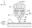
- 4 is a cross-sectional view taken along the line IV-IV in FIG. 3.
- the pressing force Fz for pressing the wiper bar 23 against the resin window 10 is zero, and the wiper bar 23 is moved along the surface of the resin window 10.
- An example of a state in which the speed V1 is zero is shown.
- the wiper bar 23 (also referred to as a wiper blade) is an elastic body held in contact with the resin window 10.
- a plate 24 (see FIG. 4) made of metal, for example, is inserted into the plate insertion groove 23H1 (see FIG. 5) of the wiper bar 23.
- the wiper holder 22 holds the wiper bar 23 so that the wiper bar 23 contacts the resin window 10.
- the wiper arm 21 supports the wiper holder 22, and the supported wiper holder 22 is pressed against the resin window 10 side with a predetermined pressing force Fz.
- the wiper arm 21 reciprocally swings along the surface of the resin window 10 while pressing the wiper holder 22 holding the wiper bar 23 toward the resin window 10 during the wiper operation.
- the maximum movement speed of the wiper 20 is the wiper 20.
- the angle ⁇ during wiper operation is about 90°
- the angular velocity ⁇ 1 during wiper operation is about 90°/sec
- the distance N1 is about 50 cm.
- the surface pressure of the wiper bar 23 (corresponding to the pressing force Fz) is pressed against the surface of the resin window 10 at about 5 to 40 N/m.
- the resin window 10 has a resin base 10A and a coating layer 10B, as shown in FIG.
- the coating layer 10B is formed on the surface of the resin window 10 on the wiper 20 side, and is formed mainly by the chemical vapor deposition method (CVD method) for the purpose of improving the surface hardness.
- CVD method chemical vapor deposition method
- a SiOx film obtained by a plasma CVD method can have various characteristics by selecting conditions such as a silicon compound as a raw material, oxygen as a decomposition gas, decomposition temperature, and charging voltage.
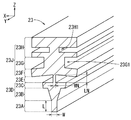
- the front shape of the wiper bar 23 shown in FIG. 5 has the same shape as the cross-sectional shape orthogonal to the longitudinal direction of the wiper bar 23.
- the wiper bar 23 has a lip portion 23A, a body portion 23D, a neck portion 23E, a holding base portion 23J, and the like in order from the side closer to the resin window 10 (see FIG. 4).
- the material of the wiper bar 23 is, for example, natural rubber or a blend of natural rubber and chloroprene rubber.
- the “one end side” is the side close to the resin window 10 in FIG. 4, and the “other end side” is the side far from the resin window 10 in FIG. 4.
- the lip portion 23A has a lip thickness as a rubber thickness in a direction along the surface of the resin window 10 (X-axis direction, see FIG. 4) in a sectional shape orthogonal to the longitudinal direction of the wiper bar 23.
- Has W The lip portion 23A has a lip length L as a rubber length in a direction toward the surface of the resin window 10 (a direction opposite to the Z-axis direction, see FIG. 4), and one end side is in contact with the resin window 10. (See FIG. 4).
- the wiper bar 23 has a constant lip thickness W over the lip length L, and the ratio (L/W) of the lip length L to the lip thickness W is greater than 0 and 2.3 or less. It is set.
- An example of the wiper bar 23 is shown in which the lip length L/lip thickness W ⁇ 1.7 is set. The reason for setting this range will be described later.
- the body portion 23D has a lower body portion 23B and an upper body portion (body connection portion) 23C from the side close to the lip portion 23A.
- one end side of the body portion 23D is connected to the other end side of the lip portion 23A, and the other end side of the body portion 23D is connected to one end of the neck portion 23E. Is connected to the side of.
- the lower body portion 23B is formed in a tapered shape so that the rubber thickness increases toward the other end side.
- the rubber thickness of the body portion 23D connected to the other end side of the lip portion 23A is substantially the same as the rubber thickness (lip thickness W) of the lip portion 23A.
- the rubber thickness of the upper body 23C is set thicker than the rubber thickness of the lower body 23B.
- the rubber thickness is set to the neck thickness WN and the rubber length is set to the neck length LN in a sectional shape orthogonal to the longitudinal direction of the wiper bar 23.
- the neck thickness WN is set thinner than the rubber thickness on the other end side of the body portion 23D, and set thinner than the rubber thickness on the one end side (holding connection portion) of the holding base portion 23J.
- the one end side of the neck portion 23E is connected to the other end side of the body portion 23D, and the other end side of the neck portion 23E is connected to the one end side of the holding base portion 23J.
- the holding base portion 23J has a bottom portion 23F, a connecting portion 23G, and a head portion 23H from the side close to the lip portion 23A in the cross-sectional shape orthogonal to the longitudinal direction of the wiper bar 23.
- the rubber thickness of the bottom portion 23F is set to be thicker than the rubber thickness of the upper body portion 23C.
- the connecting portion 23G between the bottom portion 23F and the head portion 23H forms a holder insertion groove 23G1 extending in the longitudinal direction of the wiper bar 23, and the holder insertion groove 23G1 has a wiper holder 22 as shown in FIG. The tip of the is inserted.
- a plate insertion groove 23H1 extending along the longitudinal direction of the wiper bar 23 is formed in the head portion 23H.
- a plate 24 made of metal or the like is inserted into the plate insertion groove 23H1.
- the head 23H of the holding base 23J is held by the wiper holder 22 shown in FIG.
- FIG. 6 shows the wiping speed/dynamic friction coefficient characteristics showing the relationship between the wiping speed of the wiper and the dynamic friction coefficient.
- the dynamic friction coefficient ⁇ b of the inorganic glass plate is around 0.1, and the dynamic friction coefficient ⁇ a of the resin window is about 0.3 to The range is about 0.6. That is, the dynamic friction coefficient ⁇ a of the resin window is about 3 to 6 times as large as the dynamic friction coefficient ⁇ b of the inorganic glass plate.
- the resin window has a high-hardness coating layer (the above-mentioned coating layer) formed by the chemical vapor deposition method (CVD method) on the surface on the wiper side.
- CVD method chemical vapor deposition method
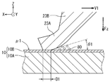
- the inorganic glass plate 210 (having a dynamic friction coefficient ⁇ b of about 0.1) and the lip portion L/W (see FIG. 5 for L and W) ⁇ 2.5 the wiper bar 123 are used.
- the case of combination will be described. In this case, the surface of the inorganic glass plate 210 is less likely to be scratched.
- the wiper bar 123 shown in FIGS. 11 and 12 is different from the wiper bar 23 of the present embodiment (see FIGS. 5 to 10; the example of lip length L/lip thickness W ⁇ 1.7) in the lip portion 123A. The difference is that the ratio (L/W) of lip length (see lip length L shown in FIG. 5) to lip thickness (see lip thickness W shown in FIG.
- the pressing force Fz for pressing the wiper bar 123 toward the inorganic glass plate 210 and the moving speed V1 for moving the wiper bar 123 along the surface of the inorganic glass plate 210 are the wiper bar 23 (FIGS. 9 and 10) described later in the present embodiment. In the case of the reference), the pressing force Fz against the resin window 10 and the moving speed V1 are the same.
- the wiper bar 123 shown in FIGS. 11 and 12 has a lip length L/lip thickness W (see FIG. 5 for L and W) of about 2.5 and a dynamic friction coefficient ⁇ b of the inorganic glass plate 210 of about 0.1. Is. Therefore, as shown in FIGS. 11 and 12, when the wiper bar 123 is moved along the surface of the inorganic glass plate 210 at the moving speed V1 while being pressed against the inorganic glass plate 210 with the pressing force Fz, The lip portion 123A of the wiper bar 123 moves relatively smoothly along the surface of the inorganic glass plate 210.
- the contact angle ⁇ b which is the angle between the surface of the inorganic glass plate 210 and the vicinity of the contact point of the lip portion 123A with the surface of the inorganic glass plate 210, is, for example, about 30°.
- the contact width Db which is the length (length in the moving direction) of the contact point with the glass plate 210, is, for example, about 1 to 2 mm. In this case, as shown in FIG.
- the contact width Db is relatively short and the dust 80 Since the period and distance of pressing to the inorganic glass plate 210 are short and the surface hardness of the inorganic glass plate 210 is relatively high, the surface of the inorganic glass plate 210 is less likely to be scratched.
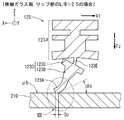
- the resin window 110 (having a dynamic friction coefficient ⁇ a of about 0.3 to about 0.6) and L/W of the lip portion (see FIG. 5 for L and W) ⁇ 2.5 A case where the wiper bar 123 is combined will be described. In this case, the surface of the resin window 110 is easily scratched.
- the wiper bar 123 shown in FIGS. 13 and 14 is the same as the wiper bar 123 shown in FIGS. 11 and 12, but the resin window 110 is used in FIGS. 13 and 14 instead of the inorganic glass plate.
- the pressing force Fz and the moving speed V1 in FIGS. 13 and 14 are the same as the pressing force Fz and the moving speed V1 in FIGS. 11 and 12.
- the dynamic friction coefficient ⁇ a (about 0.3 to about 0.6) of the resin window 110 is larger than the dynamic friction coefficient ⁇ b (about 0.1) of the inorganic glass plate 210. Therefore, even when the same wiper bar 123 as in FIGS. 11 and 12 is used, the lip portion 123A is pulled by a larger force on the side opposite to the moving direction. As a result, the amount of deflection of the lip portion 123A increases, and the contact angle ⁇ a becomes smaller.
- the resin window 110 has a resin base 110A and a coating layer 110B.
- the dynamic friction coefficient ⁇ a of the surface of the coating layer 110B on the side of the wiper bar 123 is about 0.3 to about 0.6. While the lip length L/lip thickness W (L and W, see FIG. 5) is set to about 2.5, the wiper bar 123 is pressed against the resin window 110 by the pressing force Fz, and at the moving speed V1 of the resin window 110. When the surface is moved, the lip portion 123A of the wiper bar 123 does not move as smoothly as in the case of the inorganic glass plate 210 (the dynamic friction coefficient ⁇ b is about 0.1). Therefore, the contact angle ⁇ a shown in FIGS.
- the contact width Da shown in FIGS. 13 and 14 is considerably longer than the contact width Db (see FIGS. 11 and 12) in the case of the inorganic glass plate 210.
- the contact width Da is the contact width in the case of the inorganic glass plate 210. Since it is considerably longer than Db (see FIG.
- the period and distance for which the dust 80 is pressed against the resin window 110 is considerably longer than that of the inorganic glass plate 210. Further, since the surface hardness of the resin window 110 is lower than that of the inorganic glass plate, the surface of the resin window 110 is easily scratched.
- the wiper bar 23 can suppress the above-mentioned conspicuous scratches from being attached to the resin window 10. ..
- the target resin window 10 has a resin base portion 10A and a coating layer 10B, as shown in FIGS. 9 and 10.
- the coating layer 10B is formed by the chemical vapor deposition method (CVD method) and has a hardness higher than that of the resin base portion 10A.
- the dynamic friction coefficient of the surface of the coating layer 10B is about 0.3 to about 0.6.
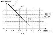
- FIG. 7 shows a moving direction of a portion where the lip portion 23A is in contact with the resin window 10 when the wiper bar is moved with respect to the resin window 10 at the pressing force Fz and the moving speed V1 described above.
- the result obtained by experiment is shown about the contact width/damage evaluation level characteristic which is the relationship between the contact width D1 which is the length (see FIG. 10) and the scratch evaluation level.
- the scratch evaluation levels 0 to 5 are set based on the number of scratches that can be visually confirmed in a unit area. For example, the scratch evaluation level 5 indicates that the number of scratches in the unit area is the smallest, and the scratch evaluation level 3 or higher is set as the pass level (it is considered that the resin window is less likely to have noticeable scratches). ..
- the scratch evaluation level which is the pass level. It was confirmed to be 3 or more.
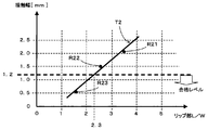
- FIG. 8 is based on the result of FIG. 7, and when the wiper bar is moved to the resin window 10 at the pressing force Fz and the moving speed V1 described above, the lip length L/L of the lip portion 23A.
- the result obtained by the experiment about the lip part L/W/contact width characteristic which is the relationship between the lip thickness W (L and W are shown in FIG. 5) and the contact width is shown.
- the lip portion L/W should be 2.3 or less. That is, it was confirmed that when the lip portion L/W is set to be larger than 0 and 2.3 or less, the contact width can be 1.2 mm or less, and the scratch evaluation level 3 or more can be secured.
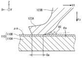
- the resin window 10 (the coefficient of dynamic friction ⁇ 1 is about 0.3 to about 0.6) and L/W of the lip portion 23A (see FIG. 5 for L and W) ⁇ 1.7.
- the case where the Waipara bar 23 of is combined will be described. In this case, the surface of the resin window 10 is unlikely to be markedly scratched.
- the pressing force Fz and the moving speed V1 in FIGS. 9 and 10 are the same as the pressing force Fz and the moving speed V1 in FIGS. 11 to 14. From the results of FIG. 7 and FIG. 8, it is sufficient to set the lip portion L/W to be larger than 0 and 2.3 or less. Therefore, an example in which the lip portion L/W is set to 1.7 will be described. ..
- the above-described coating layer 10B is formed on the surface of the resin window 10.
- the wiper bar 23 having the lip portion L/W (lip length L/lip thickness W) set to about 1.7 is pressed against the resin window 10 with the pressing force Fz.
- the lip portion 23A of the wiper bar 23 moves smoothly as in the case of the inorganic glass plate 210 (see FIGS. 11 and 12).
- the contact angle ⁇ 1 shown in FIGS. 9 and 10 is the same as the contact angle ⁇ b in the case of the inorganic glass plate 210 (see FIGS. 11 and 12).
- the contact width D1 shown in FIGS. 9 and 10 is 1.2 mm or less. In this case, as shown in FIG.
- the contact width D1 is 1.2 mm or less, The period and distance in which the dust 80 is pressed against the resin window 10 becomes shorter. As a result, the surface of the resin window 10 is less likely to be scratched.
- the lip portion L/W may be larger than 0 and not more than 2.3, and if the lip portion L/W is made smaller from 2.3 to 0, the results are shown in FIGS. 9 and 10. Since the contact angle ⁇ 1 indicated by is gradually increased, the contact width D1 is also gradually decreased (see FIG. 8). Therefore, as shown in FIG. 7, the scratch evaluation level also gradually increases, so when the lip portion L/W is reduced from 2.3 to 0, the surface of the resin window 10 becomes conspicuous. The scratches are less likely to attach.
Landscapes
- Engineering & Computer Science (AREA)
- Mechanical Engineering (AREA)
- Window Of Vehicle (AREA)
- Ink Jet (AREA)
Priority Applications (3)
| Application Number | Priority Date | Filing Date | Title |
|---|---|---|---|
| DE112019006506.8T DE112019006506T5 (de) | 2018-12-25 | 2019-12-02 | Wischerstruktur für ein Harzfenster und Wischergummi |
| US17/417,158 US20220073034A1 (en) | 2018-12-25 | 2019-12-02 | Wiper structure for resin window and wiper rubber |
| CN201980085710.XA CN113226866A (zh) | 2018-12-25 | 2019-12-02 | 树脂窗用刮水器构造和刮水器刮片 |
Applications Claiming Priority (2)
| Application Number | Priority Date | Filing Date | Title |
|---|---|---|---|
| JP2018240946A JP2020100338A (ja) | 2018-12-25 | 2018-12-25 | 樹脂ガラス用ワイパ構造及びワイパラバー |
| JP2018-240946 | 2018-12-25 |
Publications (1)
| Publication Number | Publication Date |
|---|---|
| WO2020137369A1 true WO2020137369A1 (ja) | 2020-07-02 |
Family
ID=71125830
Family Applications (1)
| Application Number | Title | Priority Date | Filing Date |
|---|---|---|---|
| PCT/JP2019/047003 WO2020137369A1 (ja) | 2018-12-25 | 2019-12-02 | 樹脂ウィンド用ワイパ構造及びワイパラバー |
Country Status (5)
Families Citing this family (2)
| Publication number | Priority date | Publication date | Assignee | Title |
|---|---|---|---|---|
| JP2023095727A (ja) * | 2021-12-24 | 2023-07-06 | キヤノン株式会社 | ワイパー装置 |
| EP4454956A1 (en) * | 2021-12-24 | 2024-10-30 | Canon Kabushiki Kaisha | Wiper device |
Citations (12)
| Publication number | Priority date | Publication date | Assignee | Title |
|---|---|---|---|---|
| JPS58188739A (ja) * | 1982-04-28 | 1983-11-04 | Honda Motor Co Ltd | 自動二輪車におけるワイパ装置 |
| JPH06135300A (ja) * | 1992-10-29 | 1994-05-17 | Nissan Motor Co Ltd | ワイパー装置 |
| JPH0769176A (ja) * | 1994-06-17 | 1995-03-14 | Jidosha Denki Kogyo Co Ltd | ワイパブレード |
| JP2001206200A (ja) * | 2000-01-26 | 2001-07-31 | Denso Corp | 撥水コートウインドシールド |
| JP2003253214A (ja) * | 2002-03-05 | 2003-09-10 | Akurosu Kk | コーティング組成物およびワイパーブレード |
| JP2003341482A (ja) * | 2002-05-29 | 2003-12-03 | Toyota Industries Corp | ワイパー装置及びその払拭方法 |
| JP2005145166A (ja) * | 2003-11-12 | 2005-06-09 | Shin Etsu Polymer Co Ltd | ワイパーブレード |
| JP2006117105A (ja) * | 2004-10-21 | 2006-05-11 | Jidosha Denki Kogyo Co Ltd | ワイパブレード |
| JP2012091670A (ja) * | 2010-10-27 | 2012-05-17 | Honda Motor Co Ltd | 車両用ワイパー |
| JP2014218103A (ja) * | 2013-05-02 | 2014-11-20 | 株式会社レニアス | 発熱層を有する車両用樹脂ガラスとその製造方法 |
| JP2017109683A (ja) * | 2015-12-18 | 2017-06-22 | 株式会社小糸製作所 | 発熱体を備えた車窓用樹脂ガラス |
| JP2017149380A (ja) * | 2016-02-26 | 2017-08-31 | イビデン株式会社 | 樹脂製リアウインドウ及び樹脂製ウインドウ |
Family Cites Families (11)
| Publication number | Priority date | Publication date | Assignee | Title |
|---|---|---|---|---|
| JPH0831924B2 (ja) | 1986-10-14 | 1996-03-27 | キヤノン株式会社 | 通信装置 |
| JP2682110B2 (ja) * | 1989-02-28 | 1997-11-26 | 橋本フォーミング工業株式会社 | 合成樹脂製ウインドウの製造方法 |
| US5251357A (en) * | 1991-05-03 | 1993-10-12 | Alberee Ltd., Inc. | Windshield wiper blade with deformable internal cavity |
| JPH0577691A (ja) * | 1991-09-17 | 1993-03-30 | Asmo Co Ltd | ワイパブレードラバーおよびその製造方法 |
| JPH07246916A (ja) * | 1994-03-11 | 1995-09-26 | Nissan Motor Co Ltd | ワイパー装置 |
| JP2004243917A (ja) | 2003-02-14 | 2004-09-02 | Yokohama Rubber Co Ltd:The | ワイパブレードの設計方法およびワイパブレード |
| JP2009056925A (ja) * | 2007-08-31 | 2009-03-19 | Daikyo Nishikawa Kk | 車両用ウインドガラス |
| US8443483B2 (en) * | 2010-08-30 | 2013-05-21 | GM Global Technology Operations LLC | Wiper blade for vehicle window wiper |
| DE102013201093B4 (de) * | 2013-01-24 | 2020-10-22 | Robert Bosch Gmbh | Wischgummi mit Austauschhinweis |
| CN103612618A (zh) * | 2013-12-03 | 2014-03-05 | 贵阳万江航空机电有限公司 | 一种新型结构的汽车刮水器刮片胶条 |
| JP6230432B2 (ja) * | 2014-01-30 | 2017-11-15 | 株式会社ミツバ | ワイパブレード |
-
2018
- 2018-12-25 JP JP2018240946A patent/JP2020100338A/ja active Pending
-
2019
- 2019-12-02 CN CN201980085710.XA patent/CN113226866A/zh active Pending
- 2019-12-02 WO PCT/JP2019/047003 patent/WO2020137369A1/ja active Application Filing
- 2019-12-02 DE DE112019006506.8T patent/DE112019006506T5/de not_active Ceased
- 2019-12-02 US US17/417,158 patent/US20220073034A1/en not_active Abandoned
Patent Citations (12)
| Publication number | Priority date | Publication date | Assignee | Title |
|---|---|---|---|---|
| JPS58188739A (ja) * | 1982-04-28 | 1983-11-04 | Honda Motor Co Ltd | 自動二輪車におけるワイパ装置 |
| JPH06135300A (ja) * | 1992-10-29 | 1994-05-17 | Nissan Motor Co Ltd | ワイパー装置 |
| JPH0769176A (ja) * | 1994-06-17 | 1995-03-14 | Jidosha Denki Kogyo Co Ltd | ワイパブレード |
| JP2001206200A (ja) * | 2000-01-26 | 2001-07-31 | Denso Corp | 撥水コートウインドシールド |
| JP2003253214A (ja) * | 2002-03-05 | 2003-09-10 | Akurosu Kk | コーティング組成物およびワイパーブレード |
| JP2003341482A (ja) * | 2002-05-29 | 2003-12-03 | Toyota Industries Corp | ワイパー装置及びその払拭方法 |
| JP2005145166A (ja) * | 2003-11-12 | 2005-06-09 | Shin Etsu Polymer Co Ltd | ワイパーブレード |
| JP2006117105A (ja) * | 2004-10-21 | 2006-05-11 | Jidosha Denki Kogyo Co Ltd | ワイパブレード |
| JP2012091670A (ja) * | 2010-10-27 | 2012-05-17 | Honda Motor Co Ltd | 車両用ワイパー |
| JP2014218103A (ja) * | 2013-05-02 | 2014-11-20 | 株式会社レニアス | 発熱層を有する車両用樹脂ガラスとその製造方法 |
| JP2017109683A (ja) * | 2015-12-18 | 2017-06-22 | 株式会社小糸製作所 | 発熱体を備えた車窓用樹脂ガラス |
| JP2017149380A (ja) * | 2016-02-26 | 2017-08-31 | イビデン株式会社 | 樹脂製リアウインドウ及び樹脂製ウインドウ |
Also Published As
| Publication number | Publication date |
|---|---|
| US20220073034A1 (en) | 2022-03-10 |
| CN113226866A (zh) | 2021-08-06 |
| JP2020100338A (ja) | 2020-07-02 |
| DE112019006506T5 (de) | 2021-09-23 |
Similar Documents
| Publication | Publication Date | Title |
|---|---|---|
| US8347450B2 (en) | Wiper blade | |
| WO2020137369A1 (ja) | 樹脂ウィンド用ワイパ構造及びワイパラバー | |
| US20130305478A1 (en) | Wiper blade | |
| JP2007153324A (ja) | ワイパーブレード | |
| JP2010023710A (ja) | ブレードラバーの製造方法およびワイパブレード | |
| US8627539B2 (en) | Connector device for coupling wiper arm | |
| JP2006111258A (ja) | 自動車用ワイパー | |
| JP2015500174A (ja) | ウィンドスクリーン用ワイパーアーム | |
| WO2013073649A1 (ja) | カウルルーバ | |
| JP2018172063A (ja) | 車体構造 | |
| JP2008168796A (ja) | 車両用ワイパ装置 | |
| KR101729145B1 (ko) | 압력 분산형 와이퍼 블레이드 | |
| GB2287179A (en) | Wiper for motor vehicles | |
| US20130312210A1 (en) | Wiper blade | |
| US20160221539A1 (en) | Wiper lip for a windshield wiper device | |
| CN100532166C (zh) | 刮水器装置 | |
| JP4420403B2 (ja) | カウル構造 | |
| US11247640B2 (en) | Wiper apparatus having arrangement structure between wiper arm tip and vertebra | |
| JP2009113737A (ja) | 車両用ワイパ装置 | |
| JP2016113146A (ja) | ワイパーブレード | |
| KR20150068041A (ko) | 차량용 와이퍼의 구조 | |
| KR101845444B1 (ko) | 와이퍼 블레이드용 코팅 조성물 | |
| JP2019031142A (ja) | ワイパブレード | |
| JP6228842B2 (ja) | ワイパブレード及び車両用ワイパ装置 | |
| US20250042366A1 (en) | End cap and windscreen-wiper blade for a motor vehicle |
Legal Events
| Date | Code | Title | Description |
|---|---|---|---|
| 121 | Ep: the epo has been informed by wipo that ep was designated in this application |
Ref document number: 19904351 Country of ref document: EP Kind code of ref document: A1 |
|
| 122 | Ep: pct application non-entry in european phase |
Ref document number: 19904351 Country of ref document: EP Kind code of ref document: A1 |