WO2020137117A1 - 円筒型スパッタリングターゲットの製造方法 - Google Patents
円筒型スパッタリングターゲットの製造方法 Download PDFInfo
- Publication number
- WO2020137117A1 WO2020137117A1 PCT/JP2019/041241 JP2019041241W WO2020137117A1 WO 2020137117 A1 WO2020137117 A1 WO 2020137117A1 JP 2019041241 W JP2019041241 W JP 2019041241W WO 2020137117 A1 WO2020137117 A1 WO 2020137117A1
- Authority
- WO
- WIPO (PCT)
- Prior art keywords
- backing tube
- target material
- target
- bonding
- scraping plate
- Prior art date
- Legal status (The legal status is an assumption and is not a legal conclusion. Google has not performed a legal analysis and makes no representation as to the accuracy of the status listed.)
- Ceased
Links
Images



Classifications
-
- C—CHEMISTRY; METALLURGY
- C23—COATING METALLIC MATERIAL; COATING MATERIAL WITH METALLIC MATERIAL; CHEMICAL SURFACE TREATMENT; DIFFUSION TREATMENT OF METALLIC MATERIAL; COATING BY VACUUM EVAPORATION, BY SPUTTERING, BY ION IMPLANTATION OR BY CHEMICAL VAPOUR DEPOSITION, IN GENERAL; INHIBITING CORROSION OF METALLIC MATERIAL OR INCRUSTATION IN GENERAL
- C23C—COATING METALLIC MATERIAL; COATING MATERIAL WITH METALLIC MATERIAL; SURFACE TREATMENT OF METALLIC MATERIAL BY DIFFUSION INTO THE SURFACE, BY CHEMICAL CONVERSION OR SUBSTITUTION; COATING BY VACUUM EVAPORATION, BY SPUTTERING, BY ION IMPLANTATION OR BY CHEMICAL VAPOUR DEPOSITION, IN GENERAL
- C23C14/00—Coating by vacuum evaporation, by sputtering or by ion implantation of the coating forming material
- C23C14/22—Coating by vacuum evaporation, by sputtering or by ion implantation of the coating forming material characterised by the process of coating
- C23C14/34—Sputtering
- C23C14/3407—Cathode assembly for sputtering apparatus, e.g. Target
-
- C—CHEMISTRY; METALLURGY
- C23—COATING METALLIC MATERIAL; COATING MATERIAL WITH METALLIC MATERIAL; CHEMICAL SURFACE TREATMENT; DIFFUSION TREATMENT OF METALLIC MATERIAL; COATING BY VACUUM EVAPORATION, BY SPUTTERING, BY ION IMPLANTATION OR BY CHEMICAL VAPOUR DEPOSITION, IN GENERAL; INHIBITING CORROSION OF METALLIC MATERIAL OR INCRUSTATION IN GENERAL
- C23C—COATING METALLIC MATERIAL; COATING MATERIAL WITH METALLIC MATERIAL; SURFACE TREATMENT OF METALLIC MATERIAL BY DIFFUSION INTO THE SURFACE, BY CHEMICAL CONVERSION OR SUBSTITUTION; COATING BY VACUUM EVAPORATION, BY SPUTTERING, BY ION IMPLANTATION OR BY CHEMICAL VAPOUR DEPOSITION, IN GENERAL
- C23C14/00—Coating by vacuum evaporation, by sputtering or by ion implantation of the coating forming material
- C23C14/22—Coating by vacuum evaporation, by sputtering or by ion implantation of the coating forming material characterised by the process of coating
- C23C14/34—Sputtering
-
- H—ELECTRICITY
- H01—ELECTRIC ELEMENTS
- H01J—ELECTRIC DISCHARGE TUBES OR DISCHARGE LAMPS
- H01J37/00—Discharge tubes with provision for introducing objects or material to be exposed to the discharge, e.g. for the purpose of examination or processing thereof
- H01J37/32—Gas-filled discharge tubes
- H01J37/34—Gas-filled discharge tubes operating with cathodic sputtering
- H01J37/3411—Constructional aspects of the reactor
- H01J37/3414—Targets
- H01J37/3423—Shape
-
- H—ELECTRICITY
- H01—ELECTRIC ELEMENTS
- H01J—ELECTRIC DISCHARGE TUBES OR DISCHARGE LAMPS
- H01J37/00—Discharge tubes with provision for introducing objects or material to be exposed to the discharge, e.g. for the purpose of examination or processing thereof
- H01J37/32—Gas-filled discharge tubes
- H01J37/34—Gas-filled discharge tubes operating with cathodic sputtering
- H01J37/3488—Constructional details of particle beam apparatus not otherwise provided for, e.g. arrangement, mounting, housing, environment; special provisions for cleaning or maintenance of the apparatus
- H01J37/3491—Manufacturing of targets
-
- H—ELECTRICITY
- H01—ELECTRIC ELEMENTS
- H01J—ELECTRIC DISCHARGE TUBES OR DISCHARGE LAMPS
- H01J37/00—Discharge tubes with provision for introducing objects or material to be exposed to the discharge, e.g. for the purpose of examination or processing thereof
- H01J37/32—Gas-filled discharge tubes
- H01J37/34—Gas-filled discharge tubes operating with cathodic sputtering
- H01J37/3411—Constructional aspects of the reactor
- H01J37/3435—Target holders (includes backing plates and endblocks)
Definitions
- the present invention relates to a method for manufacturing a cylindrical sputtering target used in a sputtering device.
- the present application claims priority to Japanese Patent Application No. 2018-242356 filed in Japan on Dec. 26, 2018, and the content thereof is incorporated herein.
- a sputtering device that performs sputtering while rotating a cylindrical sputtering target.
- a cylindrical sputtering target used in this type of sputtering apparatus has an inner peripheral surface of a cylindrical target material bonded to an outer peripheral surface of a cylindrical backing tube, as disclosed in Patent Document 1.
- the same or similar undercoating joining material as the joining material is applied to the outer circumferential surface of the cylindrical backing tube and the inner circumferential surface of the cylindrical target material to form the undercoating film.
- a cylindrical backing tube is inserted into the target material, a gap for a joint portion is provided between the two, and the target material and the cylindrical backing tube are kept in a heated state, and the molten state is joined to the gap.
- a joining method is known in which a material is supplied to fill a gap. Indium (In) is often used as the bonding material.
- the surface of the target material and the surface-treated bonding material of the cylindrical backing tube undergoes cooling after the surface-treatment and reheating before bonding for filling the bonding material into the gap between the both, and the surface is oxidized, An oxide film is formed.
- the oxide film formed on the surface of the undercoating bonding material hinders the contact between the filling bonding material and the undercoating bonding material, resulting in a defective bonding.
- the target material has become longer with the increase in the size of the substrate to be sputtered, and from the viewpoint of improving production efficiency, there is a tendency to increase the power density during sputtering film formation, and it is also desired to improve the bonding strength. There is.
- Patent Document 2 As a countermeasure against this, for example, in Patent Document 2, after a molten bonding material is filled in a gap between a cylindrical target material and a cylindrical backing tube, a steel wire or a steel plate is inserted to fill the space between them. It is disclosed that the filled bonding material and the base treatment bonding material are integrated by stirring.
- Patent Document 3 a powder substance having a specific gravity lower than that of a solder material, which is a bonding material, is placed in the space between the cylindrical target material and the cylindrical backing tube, and then molten solder is injected into the space to form the powder material. While being floated on the liquid surface of the solder material, the powder material is injected while being vibrated to physically agitate the solder material.
- Patent Document 4 a solid bonding material is filled in the gap between the cylindrical target material and the cylindrical backing tube, and the bonding material is heated and melted to reduce the contact area between the surface to be treated and the atmosphere. It suppresses the generation of oxide film on the surface of the target material and the surface of the cylindrical backing tube which has been subjected to the surface treatment.
- Patent Document 2 it takes time and labor for stirring the bonding material. Moreover, in order to remove the oxide film of the applied bonding material over the entire surface, it is necessary to stir the entire gap between the target material and the backing tube, and there is a possibility that defective bonding will occur in the part where stirring is insufficient. Is high. The same is true for Patent Document 3, and a vibration source for vibrating the powder substance is required as a separate device, and if the agitation of the solder material due to the vibration of the powder substance is not sufficient, it may lead to defective bonding. There is.
- Patent Document 4 if an oxide film adheres to the outer peripheral surface of the solid bonding material and the inner and outer peripheral surfaces of the target material and the backing tube before bonding, it is difficult to avoid defective bonding. Therefore, before placing the target material in the backing tube, it is necessary to remove the oxide film formed on the surface of the bonding material, the target material, and the inner and outer peripheral surfaces of the backing tube.
- the present invention prevents the occurrence of bonding defects due to the oxide film on the surface of the bonding material that has been subjected to the base treatment, without increasing the need for a special process for removing the oxide film, and improves the yield.
- the purpose is to let.
- the gap between the cylindrical target material and the outer peripheral surface of the cylindrical backing tube inserted inside the cylindrical target material is filled with a bonding material.
- a scraping plate that can be disposed so as to project in the radial direction in the gap is provided along the circumferential direction, and the undercoating layer is heated to The surface is at least in a semi-molten state, and the backing tube is inserted into the target material while scraping off the oxide film formed on the surface of the undercoat layer by the scraping plate.
- the surface of the base treatment layer formed in the base treatment step is oxidized during cooling after applying the base treatment bonding material and during reheating during the bonding step, and as a result, an oxide film is formed on the surface of the base treatment layer. ..
- the oxide film on the surface of the undercoating layer is removed by the scraping plate with the surface of the undercoating layer being at least in a semi-molten state during the joining process. Integrating the joining material and the undercoating joining material is not hindered by the oxide film, and the joining can be performed firmly.
- the oxide film can be removed by inserting the backing tube into the target material, it is possible to reliably remove the oxide film without the need for a special treatment step for removing the oxide film, and the work is easy. Is.
- the target material is composed of a plurality of divided target materials divided in a lengthwise direction, and a plate-shaped annular member is provided between the divided target materials.
- a spacer is provided, and the inner peripheral portion of the annular spacer is formed as the scraping plate by protruding inward in the radial direction, and the inner periphery of the annular spacer is inserted when the backing tube is inserted into the target material. It is advisable to scrape off the oxide film of the undercoat layer on the outer peripheral surface of the backing tube.
- annular spacer is provided between the divided target materials to prevent the bonding material from flowing out. Since the annular spacer can be used as a scraping plate, the work of removing the oxide film can be further simplified and the oxide film can be efficiently removed.
- the scraping plate may be provided at an end of the target material on the side where the backing tube is inserted. ..
- the oxide film of the undercoating layer on the outer peripheral surface of the backing tube can be scraped off by the scraping plate at the end of the target material.
- the oxide film on the entire outer peripheral surface of the backing tube can be removed.
- the scraping plate is provided at an end of the backing tube on the side where the backing tube is inserted into the target material.
- the outer peripheral portion of the scraping plate may scrape off the oxide film of the undercoat layer on the inner peripheral surface of the target material.
- an oxide film can be scraped off by the operation which inserts a backing tube into a target material, without a separate process of removing an oxide film, workability is good, and generation
- FIG. 4 is a vertical cross-sectional view showing a state where the backing tube of FIG. 3 is lowered. It is a top view which shows a scraping board. It is a longitudinal cross-sectional view which shows the state in the middle of manufacture in the manufacturing method of 2nd Embodiment. It is a longitudinal cross-sectional view which shows the state in the middle of manufacture in the manufacturing method of 3rd Embodiment.
- a cylindrical backing tube 3 is inserted into a cylindrical target material 2, and the inner peripheral surface of the target material 2 and the cylindrical backing tube 3 (backing tube) The outer peripheral surface of 3) is joined via the joining portion 4.
- the target material 2 and the backing tube 3 are arranged with their central axes aligned.
- the target material 2 is long, it is generally configured by connecting a plurality of divided target materials 2a divided in the length direction.
- the target material 2 is an inner diameter made of a metal such as copper or silver, or a ceramic such as AZO which is an oxide sintered body of Al or Zn.
- a tubular member of 120 mm to 140 mm can be used, and the backing tube 3 is made of titanium, stainless steel, or copper or copper alloy and has an outer diameter of 119 mm to 139 mm and a length of 0.5 m to 4 m.
- the target material 2 is arranged on the outer periphery of the cylindrical backing tube 3 in a state in which a plurality of short divided target materials 2a having a length of about 30 cm are connected.
- a gap of about 0.5 mm to 1 mm is formed in the radial direction between the outer peripheral surfaces of the two, and the gap has a rod shape (not shown) for holding the gap.
- a spacer (not shown) may be inserted, and in this case, the target material 2 and the backing tube 3 are integrated by the joint portion 4 together with this rod-shaped spacer.
- the joining portion 4 for example, an indium alloy or pure indium having an indium content of 60 mass% or more, a tin alloy or pure tin having a tin content of 60 mass% or more is used.
- the bonding portion 4 is composed of a base material bonding material applied to the target material 2 and the backing tube 3, and a filling bonding material filled in the gaps between them, and is provided by integrally solidifying them.
- ⁇ Production method of cylindrical sputtering target> A first embodiment of the method for manufacturing the cylindrical sputtering target 1 will be described.
- the outer peripheral surface of the cylindrical backing tube 3 and the inner peripheral surface of the target material 2 are used as joint surfaces, and they are joined by a joint material provided between these joint surfaces.
- the heating process of the target material 2 and the backing tube 3, the base treatment process of applying the base treatment bonding material to the target material 2 and the backing tube 3, and the applied base treatment bonding material are performed.
- Undercoating bonding material cooling step of cooling and solidifying reheating step of reheating the solidified undercoating bonding material, bonding material filling step of filling the gap between the target material 2 and the backing tube 3 with the bonding material (bonding) Step), and a bonding material cooling step of cooling and filling the filled bonding material.
- the steps will be described below in order.
- the target material 2 and the backing tube 3 are heated, and the inner peripheral surface of the target material 2 and the outer peripheral surface of the backing tube 3, which are the joint surfaces of these, are heated to a temperature equal to or higher than the melting point (or liquidus temperature) of the base treated joint material. To do.
- the molten undercoating bonding material is applied to the inner circumferential surface of the heated target material 2 and the outer circumferential surface of the backing tube 3 to form the undercoating layers 41a and 41b, respectively.
- stains and oxidation on the inner peripheral surface of the target material 2 and the outer peripheral surface of the backing tube 3 are performed by applying the base treatment bonding material while applying ultrasonic vibration with an ultrasonic soldering iron (not shown) equipped with a heater. The removal of the film is promoted and the surface-treated bonding material can be made to fit on these surfaces.
- the base treatment step may be performed in the air, but when it is performed in an inert atmosphere such as argon or nitrogen, the surface treatment layers 41a and 41b formed of the base treatment bonding material are prevented from being oxidized. Therefore, it is desirable to carry out in such an atmosphere.
- an inert atmosphere such as argon or nitrogen
- the cooling process for the base treatment bonding material is performed by an appropriate cooling means after the base treatment process.
- the undercoating bonding material is solidified, and the undercoating layers 41a and 41b are formed on the inner peripheral surface of the target material 2 and the outer peripheral surface of the backing tube 3.
- the oxide film 42 is formed through the next reheating step.
- the undercoating layer 41a of the target material 2 is thicker than the undercoating layer of the backing tube 3. It is good to do it.
- the undercoating layer 41b of the backing tube 3 has a thickness of 10 ⁇ m or more and 50 ⁇ m, while the undercoating layer 41a of the target material 2 has a thickness of 100 ⁇ m or more and 800 ⁇ m or less.
- the target material 2 on which the base treatment layer 41a is formed is vertically mounted.
- a recess 12 is provided on the surface of the mounting table 11, and the target material 2 is arranged so as to surround the recess 12.
- the lower end of the backing tube 3 is closed with a stopper 6 to prevent the bonding material from entering the backing tube 3.
- the filling material 40 is filled in the recess 12 in a molten state.
- the filling bonding material 40 the same material as the base treatment bonding material is used, and in this example, pure indium or indium alloy is filled. In this case, the annular spacer 5 is interposed between the divided target materials 2a connected vertically.
- the annular spacer 5 absorbs a dimensional error in the lengthwise direction of the divided target material 2a and the surface roughness of the end surface, and has a function of coaxially arranging the divided target material 2a and a gap generated between the divided target materials 2a. It has the function of packing to close, and the divided target materials 2a can be accurately connected to each other in the length direction (height direction).
- the annular spacer 5 may be formed of an elastic resin material or the like, and is formed of PTFE (polytetrafluoroethylene) in this embodiment.
- the inner peripheral portion of the annular spacer 5 projects inward in the radial direction of the divided target material 2a, and the inner diameter thereof is substantially the same as the outer diameter of the backing tube 3 (matched diameter, slightly smaller diameter or slightly larger diameter). ), and functions as a scraping plate in the joining step described later. Since the annular spacer 5 is removed after joining the target material 2 and the backing tube 3, the outer diameter of the annular spacer 5 is set to be larger than the outer diameter of the target material 2 for easy removal.
- the annular spacer (scraping plate) 5 is provided with a hole 51 and a cutout 52.
- the holes 51 and the notches 52 are configured such that the molten filling bonding material can flow through the holes 51 and the notches 52 in the joining step described later.
- the holes 51 and the notches 52 may be provided in any shape other than the shape shown in FIG. 5, the formation position, and the number. If the molten filling bonding material can pass, the holes 51 and the cut portions 52 may be formed. Only one of 51 and the cutout 52 may be formed.
- a tray 7 for receiving the filling bonding material 40 overflowing from the gap between the target material 2 and the backing tube 3 is provided at the upper end of the target material 2. Then, as shown in FIG.
- the backing tube 3 is coaxially arranged above the target material 2, and these are heated by a heater (not shown) arranged around the target material 2. For example, by heating at 180 to 300° C. for 1 to 2 hours, the base treatment layers 41a and 41b are brought into a molten or at least semi-molten state. As described above, since the undercoating layer 41a of the target material 2 is formed to be thick, the oxide film 42 is easily destroyed by being drooped down by its own weight during melting and flowing down.
- the backing tube 3 is inserted into the inside of the target material 2 from above the target material 2 while keeping a constant gap, and the lower end side of the backing tube 3 is inserted into the recess 12 of the mounting table 11. .. Then, as shown in FIG. 4, when the lower end of the backing tube 3 is inserted into the recess 12, the inner peripheral surface of the target material 2 and the outer peripheral surface of the backing tube 3 are extruded so that the filling bonding material 40 in a molten state is pushed out from the recess 12. And the filling bonding material 40 is filled between the inner peripheral surface of the target material 2 and the outer peripheral surface of the backing tube 3.
- the volume of the recess 12 of the mounting table 11 depends on the gap formed between the outer peripheral surface of the backing tube 3 and the inner peripheral surface of the target material 2 when the lower end of the backing tube 3 is inserted near the bottom surface. It is sufficient if the volume is equal to or larger than the volume, and it is preferable that the filling bonding material 40 rising in the gap slightly overflows to the upper end side of the target material 2. In this case, it can be confirmed that the filling bonding material 40 is filled between the target material 2 and the backing tube 3 without any gap in a state where the filling bonding material 40 overflows the tray 7 at the upper end of the target material 2.
- the scraping plate 5 provided on the target material 2 is formed so that the inner diameter thereof is substantially the same as the outer diameter of the backing tube 3, so that the scraping plate 5 is inserted when the backing tube 3 is inserted.
- the outer peripheral surface of the backing tube 3 is rubbed by the inner peripheral portion of the backing tube 5, and the oxide film 42 on the outer peripheral surface is scraped off.
- the oxide film 42 scraped off becomes a broken state as a film, is pushed up by the filling bonding material 40 rising in the gap, and is discharged into the receiving tray 7. Further, even if part of the oxide film 42 remains in the filling bonding material 40, the oxide film 42 is dispersed in the filling bonding material 40 and is integrated and filled in the gap.
- the undercoating layer 41b without the oxide film 42 remains thin, and the filling bonding material 40 is formed on the undercoating layer 41b. Blend evenly and integrate.
- the filling bonding material 40 is filled into the gap between the target material 2 and the backing tube 3 without any gap.
- the above-mentioned reheating step and bonding material filling step may be performed in an inert atmosphere to suppress the oxidation of the bonding material and further bond The strength can be improved.
- the target material 2 is composed of three divided target materials 2a, and the inner peripheral portion is formed so that each annular spacer 5 between each divided target material 2a functions as a scraping plate.
- each annular spacer 5 between each divided target material 2a functions as a scraping plate.
- one of the annular spacers 5 is made to have the function, and the other annular spacer has the same inner peripheral edge as the divided target material 2a.
- It may be formed to have an inner diameter, or the inner peripheral portions of all the annular spacers may be made to project radially inward from the divided target material 2a so as to function as a scraping plate.
- the annular spacer 5 is used as a scraping plate, and at the time of the bonding step, the oxide film 42 of the base treatment bonding material 41b that is at least in a semi-molten state on the outer peripheral surface of the backing tube 3 is scraped and destroyed.
- the filling bonding material 40 is filled in the gap between the backing tube 3 and the target material 2. Therefore, the filling bonding material 40 and the base treatment bonding material 41b are not hindered from being integrated by the oxide film 42, and the bonding strength of these materials can be improved and integrated, and a cylindrical sputtering target of excellent quality can be obtained. 1 can be manufactured.
- the oxide film 42 can be removed by the operation of inserting the backing tube 3 into the target material 2, and the oxide film 42 can be efficiently removed without performing a special process.
- FIG. 6 shows a state in the middle of manufacturing in the manufacturing method of the second embodiment of the present invention.
- the same parts as those in the above-described embodiment are denoted by the same reference numerals, and the description thereof will be omitted.
- the tray 71 on the upper end (the end on the side where the backing tube 3 is inserted) of the target material 2 is used as a scraping plate. That is, the inner peripheral portion of the tray 71 is projected inward in the radial direction, and its inner diameter is formed to be substantially the same as the outer diameter of the backing tube 3.
- the scraping plate (sink) 71 is used to scrape off the oxide film 42 of the base treatment layer 41b on the outer peripheral surface of the backing tube 3. ..
- the oxide film 42 is scraped off by the inner peripheral portion of the receiving tray 71.
- the tray 71 is provided with cuts or holes through which the filling bonding material 40 can pass. Since the oxide film 42 is scraped by the tray 71, the scraped oxide film remains on the scraping plate 71, and a part of the oxide film is mixed in the gap between the target material 2 and the backing tube 3. Things will be less.
- the scraping plate 5 by the annular spacer between the divided target materials 2a of the above-described first embodiment is also installed together with the saucer (scraping plate) 71 at the upper end.
- the scraping plates 5 and 71 can surely remove the oxide film 42.
- FIG. 7 shows a state in the middle of manufacturing in the manufacturing method of the third embodiment of the present invention.
- the oxide film 42 of the undercoating layer 41a on the inner peripheral surface of the target material 2 is removed by dripping down by its own weight at the time of melting by making the undercoating layer 41a thick and flowing down.
- the oxide film 42 is removed in the joining step without thickening the base treatment layer 41a. That is, the scraping plate 8 is provided at the lower end of the backing tube 3 (the end on the side where the backing tube 3 is inserted into the target material 2 ), and when the backing tube 3 is inserted into the target material 2, the scraping plate 8 is attached to the outer peripheral part of the scraping plate 8.
- the oxide film 42 of the undercoat layer 41a on the inner peripheral surface of the target material 2 is scraped off.
- the scraping plate 8 may be fixed to the plug 6 described above.
- the scraping plate 8 is formed so that the outer diameter thereof is substantially the same as the inner diameter of the target material 2 (matching diameter, slightly smaller diameter or slightly larger diameter).
- the oxide film 42 scraped from the inner peripheral surface of the target material 2 by the scraping plate 8 flows into the recess 12 and mixes with the filling bonding material 40 filled in the recess 12, but is destroyed as a film. Therefore, it is not formed into a film again.
- the undercoating bonding material is applied to both the target material 2 and the backing tube 3.
- the application of the base treatment bonding material may be omitted.
- the undercoating bonding material may be applied to at least one of the target material 2 and the backing tube 3 to form the undercoating layers 41a and 41b.
- a scraping plate may be provided on a member of the target material 2 or the backing tube 3 on which the undercoating layer is not formed.
- the target material is composed of three divided target materials, and an annular spacer as a scraping plate made of PTFE (polytetrafluoroethylene) is provided between these divided target materials, and the backing tube has a lower end at its lower end.
- a scraping plate made of PTFE (polytetrafluoroethylene) was provided.
Landscapes
- Chemical & Material Sciences (AREA)
- Engineering & Computer Science (AREA)
- Physics & Mathematics (AREA)
- Plasma & Fusion (AREA)
- Analytical Chemistry (AREA)
- Chemical Kinetics & Catalysis (AREA)
- Materials Engineering (AREA)
- Mechanical Engineering (AREA)
- Metallurgy (AREA)
- Organic Chemistry (AREA)
- Physical Vapour Deposition (AREA)
Abstract
ターゲット材の内周面とバッキングチューブの外周面との少なくとも何れか一方に下地処理接合材を塗布して下地処理層を形成する下地処理工程と、下地処理工程の後、ターゲット材内にバッキングチューブを挿入し、前記ターゲット材とバッキングチューブとの隙間に充填用接合材を充填する接合工程とを有し、前記接合工程において、ターゲット材或いはバッキングチューブの何れか一方又は双方に、隙間内に径方向に突出して配置可能な掻き取り板を周方向に沿って設けるとともに、下地処理層を加熱してその表面を少なくとも半溶融状態としておき、掻き取り板により下地処理層の表面に形成された酸化膜を掻き取りながらターゲット材内にバッキングチューブを挿入する。
Description
本発明は、スパッタリング装置に用いられる円筒型スパッタリングターゲットの製造方法に関する。
本願は、2018年12月26日に日本に出願された特願2018-242356号について優先権を主張し、その内容をここに援用する。
本願は、2018年12月26日に日本に出願された特願2018-242356号について優先権を主張し、その内容をここに援用する。
円筒型スパッタリングターゲットを回転させながらスパッタを行うスパッタリング装置が知られている。この種のスパッタリング装置に用いられる円筒型スパッタリングターゲットは、特許文献1に示されるように、円筒型バッキングチューブの外周面に円筒型のターゲット材の内周面が接合されている。
この接合においては、接合面となる円筒型バッキングチューブの外周面及び円筒型ターゲット材の内周面に接合材と同じまたは類似の下地処理接合材を塗布して下地処理被膜を形成する。その後、ターゲット材に円筒型バッキングチューブを挿入して、両者の間に接合部のための隙間を設けるとともに、ターゲット材と円筒型バッキングチューブとを加熱した状態としておき、その隙間に溶融状態の接合材を供給して隙間を充填する接合方法が知られている。接合材としてはインジウム(In)を用いることが多い。
この接合においては、接合面となる円筒型バッキングチューブの外周面及び円筒型ターゲット材の内周面に接合材と同じまたは類似の下地処理接合材を塗布して下地処理被膜を形成する。その後、ターゲット材に円筒型バッキングチューブを挿入して、両者の間に接合部のための隙間を設けるとともに、ターゲット材と円筒型バッキングチューブとを加熱した状態としておき、その隙間に溶融状態の接合材を供給して隙間を充填する接合方法が知られている。接合材としてはインジウム(In)を用いることが多い。
この場合、ターゲット材及び円筒型バッキングチューブの下地処理接合材の表面は、下地処理後の冷却及び両者の隙間へ接合材を充填するための接合前の再加熱等を経て、表面が酸化し、酸化膜が形成される。
この下地処理接合材の表面に形成された酸化膜により、充填する接合材と下地処理接合材との接触が阻害され、接合不良が生じやすい。接合不良となった円筒型スパッタリングターゲットは、全体を加熱して接合材を溶融させた後、ターゲット材をバッキングチューブから取り外し、再度、接合をやり直す作業が必要となる。一方、スパッタされる基板の大型化に伴ってターゲット材は長尺化しており、生産効率の向上の観点から、スパッタ成膜時のパワー密度を上げる傾向にあり、接合強度の向上も望まれている。
この下地処理接合材の表面に形成された酸化膜により、充填する接合材と下地処理接合材との接触が阻害され、接合不良が生じやすい。接合不良となった円筒型スパッタリングターゲットは、全体を加熱して接合材を溶融させた後、ターゲット材をバッキングチューブから取り外し、再度、接合をやり直す作業が必要となる。一方、スパッタされる基板の大型化に伴ってターゲット材は長尺化しており、生産効率の向上の観点から、スパッタ成膜時のパワー密度を上げる傾向にあり、接合強度の向上も望まれている。
この対策として、例えば特許文献2においては、円筒型ターゲット材と円筒型バッキングチューブとの隙間に溶融状態の接合材を充填した後に、鋼線や鋼板を差し込んでこれらの間に充填された接合材を撹拌し、充填した接合材と下地処理接合材とを一体化することが開示されている。
特許文献3では、円筒型ターゲット材と円筒型バッキングチューブとの空間に接合材である半田材よりも比重が軽い粉体物質を入れておき、次いで、溶融半田を空間に注入して粉体物質を半田材の液面に浮かせた状態で、粉体物質を振動させながら注入することで半田材を物理的に撹拌している。
特許文献4では、円筒型ターゲット材と円筒型バッキングチューブとの隙間に固体の接合材を充填し、この接合材を加熱して溶融することにより、下地処理面と大気中との接触面積を減らし、ターゲット材と円筒型バッキングチューブの下地処理面の酸化膜の発生を抑制している。
特許文献3では、円筒型ターゲット材と円筒型バッキングチューブとの空間に接合材である半田材よりも比重が軽い粉体物質を入れておき、次いで、溶融半田を空間に注入して粉体物質を半田材の液面に浮かせた状態で、粉体物質を振動させながら注入することで半田材を物理的に撹拌している。
特許文献4では、円筒型ターゲット材と円筒型バッキングチューブとの隙間に固体の接合材を充填し、この接合材を加熱して溶融することにより、下地処理面と大気中との接触面積を減らし、ターゲット材と円筒型バッキングチューブの下地処理面の酸化膜の発生を抑制している。
しかしながら、特許文献2の場合には、接合材を撹拌するための作業の手間がかかる。しかも、塗布された接合材の酸化膜を全面に亘って除去するために、ターゲット材とバッキングチューブとの隙間全体を撹拌する必要があり、撹拌が不十分な部分では接合不良が発生する可能性が高い。
特許文献3についても同様であり、粉体物質を振動させるための振動源が別の装置として必要になり、粉体物質の振動による半田材の撹拌が十分でない場合には、接合不良につながることがある。
特許文献4の製造方法においては、接合時前に、固体の接合材の外周面やターゲット材及びバッキングチューブの内外周面に酸化膜が付着していると、接合不良の回避が難しくなる。そのため、ターゲット材をバッキングチューブ内に配置する前に、接合材の表面や、ターゲット材、バッキングチューブの内外周面に形成された酸化膜を除去する必要が生じる。
特許文献3についても同様であり、粉体物質を振動させるための振動源が別の装置として必要になり、粉体物質の振動による半田材の撹拌が十分でない場合には、接合不良につながることがある。
特許文献4の製造方法においては、接合時前に、固体の接合材の外周面やターゲット材及びバッキングチューブの内外周面に酸化膜が付着していると、接合不良の回避が難しくなる。そのため、ターゲット材をバッキングチューブ内に配置する前に、接合材の表面や、ターゲット材、バッキングチューブの内外周面に形成された酸化膜を除去する必要が生じる。
本発明は、このような事情に鑑み、酸化膜を除去するための特別の工程を別途必要とすることなく、下地処理した接合材表面の酸化膜による接合不良の発生を防止して歩留まりを向上させることを目的としている。
(1)本発明の一態様に係る円筒型スパッタリングターゲットの製造方法は、円筒型ターゲット材と前記円筒型ターゲット材の内側に挿入した円筒型バッキングチューブの外周面との隙間を接合材で充填して接合する円筒型スパッタリングターゲットの製造方法であって、前記ターゲット材の内周面と前記バッキングチューブの外周面との少なくとも何れか一方に下地処理接合材を塗布して下地処理層を形成する下地処理工程と、下地処理工程の後、前記ターゲット材内に前記バッキングチューブを挿入し、前記ターゲット材と前記バッキングチューブとの隙間に充填用接合材を充填する接合工程とを有し、前記接合工程において、前記ターゲット材或いは前記バッキングチューブの何れか一方又は双方に、前記隙間内に径方向に突出して配置可能な掻き取り板を周方向に沿って設けるとともに、前記下地処理層を加熱してその表面を少なくとも半溶融状態としておき、前記掻き取り板により前記下地処理層の表面に形成された酸化膜を掻き取りながら前記ターゲット材内に前記バッキングチューブを挿入する。
上記下地処理工程で形成される下地処理層は、下地処理接合材塗布後の冷却中及び接合工程に際しての再加熱中に表面が酸化され、その結果、下地処理層表面に酸化膜が形成される。しかし、上記(1)の態様によれば、接合工程時に下地処理層の表面を少なくとも半溶融状態として掻き取り板で下地処理層表面の酸化膜を除去するようにしているので、新たに充填される接合材と下地処理接合材との一体化が酸化膜で阻害されることがなく強固に接合できる。しかも、ターゲット材にバッキングチューブを挿入する操作によって酸化膜を除去できるので、酸化膜を除去するための特別の処理工程を別途必要とすることなく酸化膜を確実に除去可能であり、作業が容易である。
(2)上記(1)に記載の円筒型スパッタリングターゲットの製造方法では、前記ターゲット材を長さ方向に分割した複数の分割ターゲット材により構成し、前記分割ターゲット材同士の間に板状の環状スペーサを設けるとともに、前記環状スペーサの内周部を径方向内方に突出させて前記掻き取り板として形成しておき、前記ターゲット材に前記バッキングチューブを挿入する際に、前記環状スペーサの内周部で前記バッキングチューブの外周面上の前記下地処理層の酸化膜を掻き取るとよい。
上記(2)の構成によれば、複数の分割ターゲット材により長尺のターゲット材を構成する場合、分割ターゲット材の間には接合材の流出を防止するための環状スペーサが設けられるが、この環状スペーサを掻き取り板として利用できるため、酸化膜の除去作業をより一層簡便にし、効率的に酸化膜を除去できる。
(3)上記(1)または(2)に記載の円筒型スパッタリングターゲットの製造方法では、前記掻き取り板を前記ターゲット材の前記バッキングチューブが挿入される側の端部に設けておいてもよい。
上記(3)の構成によれば、ターゲット材にバッキングチューブを挿入する際に、ターゲット材の端部の掻き取り板によってバッキングチューブの外周面の下地処理層の酸化膜を掻き取ることができるので、バッキングチューブの外周面全面の酸化膜を除去することできる。
上記(3)の構成によれば、ターゲット材にバッキングチューブを挿入する際に、ターゲット材の端部の掻き取り板によってバッキングチューブの外周面の下地処理層の酸化膜を掻き取ることができるので、バッキングチューブの外周面全面の酸化膜を除去することできる。
(4)上記(1)から(3)のいずれかに記載の円筒型スパッタリングターゲットの製造方法では、前記掻き取り板を前記バッキングチューブの前記ターゲット材に挿入する側の端部に設けておき、前記ターゲット材に前記バッキングチューブを挿入する際に、前記掻き取り板の外周部で前記ターゲット材の内周面上の前記下地処理層の酸化膜を掻き取るようにしてもよい。
上記(4)の構成によれば、ターゲット材にバッキングチューブを挿入する際に、バッキングチューブの端部の掻き取り板によってターゲット材の内周面の下地処理層の酸化膜を掻き取ることができるので、ターゲット材の内周面全面の酸化膜を除去することできる。
上記(4)の構成によれば、ターゲット材にバッキングチューブを挿入する際に、バッキングチューブの端部の掻き取り板によってターゲット材の内周面の下地処理層の酸化膜を掻き取ることができるので、ターゲット材の内周面全面の酸化膜を除去することできる。
(5)上記(1)から(4)の何れかに記載の円筒型スパッタリングターゲットの製造方法では、前記掻き取り板に前記充填用接合材が通過可能な穴又は切り込み部を形成しておくとよい。
上記(5)の構成によれば、ターゲット材とバッキングチューブとの接合工程時において、ターゲット材とバッキングチューブとの隙間に掻き取り板を配置したときに、穴又は切り込み部により接合材の流路が確保されるので、これら穴、切り込み部を介して接合材を隙間の全体に確実に充填することができる。
上記(5)の構成によれば、ターゲット材とバッキングチューブとの接合工程時において、ターゲット材とバッキングチューブとの隙間に掻き取り板を配置したときに、穴又は切り込み部により接合材の流路が確保されるので、これら穴、切り込み部を介して接合材を隙間の全体に確実に充填することができる。
本発明によれば、酸化膜を除去する工程を別途必要とすることなく、ターゲット材にバッキングチューブを挿入する操作で酸化膜を掻き取ることができて、作業性が良く、接合不良の発生を防止し、歩留まりを向上させることができる。
以下、本発明に係る円筒型スパッタリングターゲットの製造方法の実施形態について、図面を参照しながら説明する。
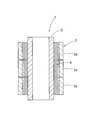
円筒型スパッタリングターゲット1は、例えば図1に示すように、円筒型のターゲット材2内に円筒型のバッキングチューブ3が挿入され、これらターゲット材2の内周面と円筒型バッキングチューブ3(バッキングチューブ3)の外周面との間が接合部4を介して接合される。この場合、ターゲット材2とバッキングチューブ3とは、中心軸が一致した状態で配置される。
円筒型スパッタリングターゲット1は、例えば図1に示すように、円筒型のターゲット材2内に円筒型のバッキングチューブ3が挿入され、これらターゲット材2の内周面と円筒型バッキングチューブ3(バッキングチューブ3)の外周面との間が接合部4を介して接合される。この場合、ターゲット材2とバッキングチューブ3とは、中心軸が一致した状態で配置される。
ターゲット材2は長尺状であることから、一般に長さ方向に分割された複数の分割ターゲット材2aを接続することで構成される。
ターゲット材2及びバッキングチューブ3の材質や寸法は特に限定されないが、例えば、ターゲット材2は、銅、銀等の金属、Al,Znの酸化物焼結体であるAZO等のセラミックスなどからなる内径120mm~140mmの筒状部材を用いることができ、バッキングチューブ3は、チタン、ステンレス鋼、または銅あるいは銅合金からなる外径119mm~139mm、長さ0.5m~4mの筒状部材を用いることができる。この場合、ターゲット材2は、長さ30cm程度の短尺の分割ターゲット材2aを複数連結した状態で円筒型バッキングチューブ3の外周に配置される。ターゲット材2内にバッキングチューブ3を挿入した状態で、両者の外周面の間には半径方向に0.5mm~1mm程度の隙間が形成され、この隙間には、隙間保持のための図示しない棒状スペーサ(図示略)が挿入されていてもよく、この場合、この棒状スペーサとともにターゲット材2及びバッキングチューブ3とが接合部4により一体化される。
接合部4は、例えばインジウム含有量が60質量%以上のインジウム合金又は純インジウム、錫含有量が60質量%以上の錫合金又は純錫等が用いられる。接合部4は、ターゲット材2、バッキングチューブ3に塗布される下地処理接合材と、これらの隙間に充填される充填用接合材とからなり、これらが一体化して固化することにより設けられる。
<円筒型スパッタリングターゲットの製造方法>
円筒型スパッタリングターゲット1の製造方法の第1実施形態について説明する。この製造方法は、円筒型バッキングチューブ3の外周面とターゲット材2の内周面とを接合面とし、これら接合面間に設けた接合材で接合する。
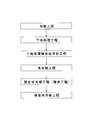
図2に示すように、第1実施形態では、ターゲット材2及びバッキングチューブ3の加熱工程、ターゲット材2及びバッキングチューブ3に下地処理接合材を塗布する下地処理工程、塗布した下地処理接合材を冷却して固化する下地処理接合材冷却工程、固化した下地処理接合材を再加熱する再加熱工程、充填用接合材をターゲット材2とバッキングチューブ3との隙間に充填する接合材充填工程(接合工程)、充填された接合材を冷却して固化する接合材冷却工程を有している。以下、工程順に説明する。
円筒型スパッタリングターゲット1の製造方法の第1実施形態について説明する。この製造方法は、円筒型バッキングチューブ3の外周面とターゲット材2の内周面とを接合面とし、これら接合面間に設けた接合材で接合する。
図2に示すように、第1実施形態では、ターゲット材2及びバッキングチューブ3の加熱工程、ターゲット材2及びバッキングチューブ3に下地処理接合材を塗布する下地処理工程、塗布した下地処理接合材を冷却して固化する下地処理接合材冷却工程、固化した下地処理接合材を再加熱する再加熱工程、充填用接合材をターゲット材2とバッキングチューブ3との隙間に充填する接合材充填工程(接合工程)、充填された接合材を冷却して固化する接合材冷却工程を有している。以下、工程順に説明する。
(加熱工程)
ターゲット材2及びバッキングチューブ3を加熱し、これらの接合面となるターゲット材2の内周面及びバッキングチューブ3の外周面を下地処理接合材の融点(又は液相線温度)以上の温度に加熱する。
ターゲット材2及びバッキングチューブ3を加熱し、これらの接合面となるターゲット材2の内周面及びバッキングチューブ3の外周面を下地処理接合材の融点(又は液相線温度)以上の温度に加熱する。
(下地処理工程)
加熱工程において、加熱状態としたターゲット材2の内周面及びバッキングチューブ3の外周面に、それぞれ溶融状態の下地処理接合材を塗布して下地処理層41a,41bをそれぞれ形成する。この場合、ヒータを搭載した超音波はんだコテ(図示略)で超音波振動を加えながら下地処理接合材を塗り込むことにより、ターゲット材2の内周面及びバッキングチューブ3の外周面における汚れや酸化膜の除去などが促進され、これらの表面に下地処理接合材をなじませることができる。
下地処理工程は、大気中で実施してもよいが、アルゴン、窒素等の不活性雰囲気にて実施すると、下地処理接合材によって形成される下地処理層41a,41bの表面の酸化を抑制することができるので、そのような雰囲気で実施することが望ましい。
加熱工程において、加熱状態としたターゲット材2の内周面及びバッキングチューブ3の外周面に、それぞれ溶融状態の下地処理接合材を塗布して下地処理層41a,41bをそれぞれ形成する。この場合、ヒータを搭載した超音波はんだコテ(図示略)で超音波振動を加えながら下地処理接合材を塗り込むことにより、ターゲット材2の内周面及びバッキングチューブ3の外周面における汚れや酸化膜の除去などが促進され、これらの表面に下地処理接合材をなじませることができる。
下地処理工程は、大気中で実施してもよいが、アルゴン、窒素等の不活性雰囲気にて実施すると、下地処理接合材によって形成される下地処理層41a,41bの表面の酸化を抑制することができるので、そのような雰囲気で実施することが望ましい。
(下地処理接合材冷却工程)
下地処理接合材冷却工程は、下地処理工程後に適宜の冷却手段により行う。これにより、下地処理接合材が固化し、ターゲット材2の内周面及びバッキングチューブ3の外周面に下地処理層41a,41bが形成された状態になる。そして、次の再加熱工程を経て、酸化膜42が形成される。
本実施形態と後述する第2実施形態においては、ターゲット材2には掻き取り板を用いて酸化膜を除去しないため、ターゲット材2の下地処理層41aは、バッキングチューブ3の下地処理層より厚くしておくとよい。例えば、バッキングチューブ3の下地処理層41bが10μm以上50μmの厚さに対して、ターゲット材2の下地処理層41aは100μm以上800μm以下の厚さとする。
下地処理接合材冷却工程は、下地処理工程後に適宜の冷却手段により行う。これにより、下地処理接合材が固化し、ターゲット材2の内周面及びバッキングチューブ3の外周面に下地処理層41a,41bが形成された状態になる。そして、次の再加熱工程を経て、酸化膜42が形成される。
本実施形態と後述する第2実施形態においては、ターゲット材2には掻き取り板を用いて酸化膜を除去しないため、ターゲット材2の下地処理層41aは、バッキングチューブ3の下地処理層より厚くしておくとよい。例えば、バッキングチューブ3の下地処理層41bが10μm以上50μmの厚さに対して、ターゲット材2の下地処理層41aは100μm以上800μm以下の厚さとする。
(再加熱工程)
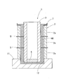
図3に示す載置台11に、下地処理層41aを形成したターゲット材2を垂直に載置する。載置台11の表面には凹部12が設けられ、この凹部12を囲むようにターゲット材2を配置する。なお、バッキングチューブ3の下端部を栓6で塞ぎ、バッキングチューブ3内への接合材の浸入を防ぐようにしておく。
凹部12には充填用接合材40を溶融状態で充填する。この充填用接合材40としては、下地処理接合材と同じ材料を用いるようにし、本例では純インジウム又はインジウム合金を充填している。
この場合、上下に連結される分割ターゲット材2aの間には、環状スペーサ5を介在させる。環状スペーサ5は、分割ターゲット材2aの長さ方向の寸法誤差や端面の表面粗さを吸収し、これら分割ターゲット材2aを同軸上に配置できる機能と、分割ターゲット材2aの間に生じる隙間を塞ぐパッキンの機能とを有しており、分割ターゲット材2a同士を長さ方向(高さ方向)に正確に接続できる。
環状スペーサ5は、弾性を有する樹脂材料などにより形成されていてもよく、本実施形態ではPTFE(ポリテトラフルオロエチレン)により形成されている。そして、環状スペーサ5は、内周部が分割ターゲット材2aの径方向内方に突出し、その内径がバッキングチューブ3の外径とほぼ同じ内径(一致した径か、わずかに小径又はわずかに大径)に形成され、後述の接合工程における掻き取り板として機能するようになっている。なお、ターゲット材2とバッキングチューブ3とを接合した後には環状スペーサ5は取り外されるため、取り出しやすいように、環状スペーサ5の外径はターゲット材2の外径よりも大きく設定される。
図3に示す載置台11に、下地処理層41aを形成したターゲット材2を垂直に載置する。載置台11の表面には凹部12が設けられ、この凹部12を囲むようにターゲット材2を配置する。なお、バッキングチューブ3の下端部を栓6で塞ぎ、バッキングチューブ3内への接合材の浸入を防ぐようにしておく。
凹部12には充填用接合材40を溶融状態で充填する。この充填用接合材40としては、下地処理接合材と同じ材料を用いるようにし、本例では純インジウム又はインジウム合金を充填している。
この場合、上下に連結される分割ターゲット材2aの間には、環状スペーサ5を介在させる。環状スペーサ5は、分割ターゲット材2aの長さ方向の寸法誤差や端面の表面粗さを吸収し、これら分割ターゲット材2aを同軸上に配置できる機能と、分割ターゲット材2aの間に生じる隙間を塞ぐパッキンの機能とを有しており、分割ターゲット材2a同士を長さ方向(高さ方向)に正確に接続できる。
環状スペーサ5は、弾性を有する樹脂材料などにより形成されていてもよく、本実施形態ではPTFE(ポリテトラフルオロエチレン)により形成されている。そして、環状スペーサ5は、内周部が分割ターゲット材2aの径方向内方に突出し、その内径がバッキングチューブ3の外径とほぼ同じ内径(一致した径か、わずかに小径又はわずかに大径)に形成され、後述の接合工程における掻き取り板として機能するようになっている。なお、ターゲット材2とバッキングチューブ3とを接合した後には環状スペーサ5は取り外されるため、取り出しやすいように、環状スペーサ5の外径はターゲット材2の外径よりも大きく設定される。
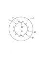
また、図5に示すように、環状スペーサ(掻き取り板)5には、穴51及び切り込み部52が設けられている。これら穴51及び切り込み部52は、後述の接合工程において、溶融した充填用接合材が穴51及び切り込み部52を通過して流通できるようになっている。なお、穴51及び切り込み部52は、図5に示された形状以外の任意の形状や形成位置及び数により設けるようにしてもよいし、溶融した充填用接合材が通過できるのであれば、穴51又は切り込み部52のいずれか一方のみが形成されるものであってもよい。
また、ターゲット材2の上端に、ターゲット材2とバッキングチューブ3との隙間からあふれ出た充填用接合材40を受けるための受け皿7を設けておく。
そして、図3に示すように、ターゲット材2の上方にバッキングチューブ3を同軸上に配置するとともに、これらをターゲット材2の周囲に配置したヒータ(図示略)により加熱する。例えば、180~300℃で1時間~2時間加熱することにより、下地処理層41a,41bを溶融又は少なくとも半溶融状態とする。前述したように、ターゲット材2の下地処理層41aは厚肉に形成されているので、溶融時に自重で垂れ下がって流れ落ちることにより、酸化膜42が破壊されやすい。
また、ターゲット材2の上端に、ターゲット材2とバッキングチューブ3との隙間からあふれ出た充填用接合材40を受けるための受け皿7を設けておく。
そして、図3に示すように、ターゲット材2の上方にバッキングチューブ3を同軸上に配置するとともに、これらをターゲット材2の周囲に配置したヒータ(図示略)により加熱する。例えば、180~300℃で1時間~2時間加熱することにより、下地処理層41a,41bを溶融又は少なくとも半溶融状態とする。前述したように、ターゲット材2の下地処理層41aは厚肉に形成されているので、溶融時に自重で垂れ下がって流れ落ちることにより、酸化膜42が破壊されやすい。
(接合材充填工程(接合工程))
図3に示すように、バッキングチューブ3を、ターゲット材2の上方から隙間を一定に保ちつつターゲット材2の内側に挿入し、このバッキングチューブ3の下端側を載置台11の凹部12に挿入する。
そして、図4に示すように、凹部12にバッキングチューブ3下端を挿入すると、溶融状態の充填用接合材40が凹部12から押し出されるようにターゲット材2の内周面とバッキングチューブ3の外周面との隙間を上昇し、ターゲット材2の内周面とバッキングチューブ3の外周面との間に充填用接合材40が充填される。
なお、載置台11の凹部12の容積は、バッキングチューブ3の下端が底面付近まで挿入されたときに、バッキングチューブ3の外周面とターゲット材2の内周面との間に形成される隙間の容積以上あればよく、隙間内を上昇した充填用接合材40がターゲット材2の上端側に若干オーバーフローする程度がよい。
この場合、充填用接合材40がターゲット材2の上端の受け皿7にあふれてきた状態でターゲット材2とバッキングチューブ3との間に充填用接合材40が隙間なく充填されたことが確認できる。
図3に示すように、バッキングチューブ3を、ターゲット材2の上方から隙間を一定に保ちつつターゲット材2の内側に挿入し、このバッキングチューブ3の下端側を載置台11の凹部12に挿入する。
そして、図4に示すように、凹部12にバッキングチューブ3下端を挿入すると、溶融状態の充填用接合材40が凹部12から押し出されるようにターゲット材2の内周面とバッキングチューブ3の外周面との隙間を上昇し、ターゲット材2の内周面とバッキングチューブ3の外周面との間に充填用接合材40が充填される。
なお、載置台11の凹部12の容積は、バッキングチューブ3の下端が底面付近まで挿入されたときに、バッキングチューブ3の外周面とターゲット材2の内周面との間に形成される隙間の容積以上あればよく、隙間内を上昇した充填用接合材40がターゲット材2の上端側に若干オーバーフローする程度がよい。
この場合、充填用接合材40がターゲット材2の上端の受け皿7にあふれてきた状態でターゲット材2とバッキングチューブ3との間に充填用接合材40が隙間なく充填されたことが確認できる。
接合工程において、ターゲット材2に設けられている掻き取り板5は、その内径がバッキングチューブ3の外径とほぼ同じに形成されているので、バッキングチューブ3が挿入される際に、掻き取り板5の内周部でバッキングチューブ3の外周面上が擦られ、この外周面上の酸化膜42が掻き取られる。掻き取られた酸化膜42は、膜としては破壊された状態となり、隙間内を上昇してくる充填用接合材40により押し上げられて、受け皿7内に排出される。また、酸化膜42の一部が充填用接合材40内に残ったとしても、充填用接合材40に分散しながら一体になって隙間内に充填される。
一方、掻き取り板5により酸化膜42が除去された後のバッキングチューブ3の外周面には、酸化膜42のない下地処理層41bが薄く残り、この下地処理層41bに充填用接合材40が均一になじんで一体化する。
一方、掻き取り板5により酸化膜42が除去された後のバッキングチューブ3の外周面には、酸化膜42のない下地処理層41bが薄く残り、この下地処理層41bに充填用接合材40が均一になじんで一体化する。
このようにしてバッキングチューブ3の下端が凹部12の底面付近まで挿入することにより、ターゲット材2とバッキングチューブ3との隙間に充填用接合材40が隙間なく充填される。
なお、必ずしも限定されるものではないが、前述の再加熱工程、接合材充填工程(少なくとも充填完了までの間)は、不活性雰囲気にて実施するとよく、接合材の酸化を抑制し、さらなる接合強度の向上が可能となる。
なお、必ずしも限定されるものではないが、前述の再加熱工程、接合材充填工程(少なくとも充填完了までの間)は、不活性雰囲気にて実施するとよく、接合材の酸化を抑制し、さらなる接合強度の向上が可能となる。
(接合材冷却工程)
ターゲット材2とバッキングチューブ3との隙間に充填用接合材40を充填した後、これを冷却して固化させることで、これらターゲット材2とバッキングチューブ3とが接合部4により一体化する。
その後、環状スペーサ5や受け皿7、はみ出した接合材等を除去し、清掃することにより円筒型スパッタリングターゲット1が得られる。このとき、環状スペーサ5を除去することで、環状スペーサ5を設けていた部分は接合部4の厚さが薄くなっている。
ターゲット材2とバッキングチューブ3との隙間に充填用接合材40を充填した後、これを冷却して固化させることで、これらターゲット材2とバッキングチューブ3とが接合部4により一体化する。
その後、環状スペーサ5や受け皿7、はみ出した接合材等を除去し、清掃することにより円筒型スパッタリングターゲット1が得られる。このとき、環状スペーサ5を除去することで、環状スペーサ5を設けていた部分は接合部4の厚さが薄くなっている。
なお、図3等に示す例では、ターゲット材2を3個の分割ターゲット材2aからなる構成とし、各分割ターゲット材2aの間の各環状スペーサ5を掻き取り板として機能させるように内周部を分割ターゲット材2aから突出させたが、掻き取り板としては、いずれか1個の環状スペーサ5にその機能を持たせるようにして、他の環状スペーサは、内周縁を分割ターゲット材2aと同じ内径に形成してもよいし、すべての環状スペーサの内周部を分割ターゲット材2aから径方向内方に突出させて掻き取り板として機能させるようにしてもよい。
以上説明した方法により、環状スペーサ5を掻き取り板として利用し、接合工程時にバッキングチューブ3の外周面上で少なくとも半溶融状態とした下地処理接合材41bの酸化膜42を掻き取って破壊しつつ、このバッキングチューブ3とターゲット材2との隙間に充填用接合材40を充填する。このため、充填用接合材40と下地処理接合材41bとの一体化が酸化膜42により阻害されることがなく、これらの接合強度を向上しつつ一体化でき、優れた品質の円筒型スパッタリングターゲット1を製造できる。
しかも、ターゲット材2にバッキングチューブ3を挿入する操作で酸化膜42を除去でき、特別な工程を経ることなく酸化膜42を効率的に除去できる。
しかも、ターゲット材2にバッキングチューブ3を挿入する操作で酸化膜42を除去でき、特別な工程を経ることなく酸化膜42を効率的に除去できる。
図6は、本発明の第2実施形態の製造方法の製造途中の状態を示している。なお、第2実施形態以降において、前記実施形態と同一部分は同一符号によって表し、その説明を省略する。以下、図6の第2実施形態においても同様とする。
第2実施形態では、ターゲット材2の上端(バッキングチューブ3が挿入される側の端部)の受け皿71を掻き取り板として利用するものである。すなわち、受け皿71の内周部を径方向内方に突出させ、その内径をバッキングチューブ3の外径とほぼ同じに形成している。そして、ターゲット材2の上方からバッキングチューブ3を挿入する際に、この掻き取り板(受け皿)71によりバッキングチューブ3の外周面の下地処理層41bの酸化膜42を掻き取るようにしたものである。この場合、隙間を上昇した充填用接合材40を受け皿71で受けつつ、この受け皿71の内周部で酸化膜42を掻き取る。受け皿71には、前述した環状スペーサ5と同様に、充填用接合材40が通過可能な切り込みや穴が設けられる。この受け皿71で酸化膜42を掻き取るため、掻き取られた酸化膜は掻き取り板71の上に残ることになり、ターゲット材2とバッキングチューブ3との隙間に酸化膜の一部が混入することは少なくなる。
なお、図6には、前述した第1実施形態の分割ターゲット材2aの間の環状スペーサによる掻き取り板5も、上端の受け皿(掻き取り板)71と合わせて設置しており、これら複数の掻き取り板5,71によって確実に酸化膜42を除去することができる。
第2実施形態では、ターゲット材2の上端(バッキングチューブ3が挿入される側の端部)の受け皿71を掻き取り板として利用するものである。すなわち、受け皿71の内周部を径方向内方に突出させ、その内径をバッキングチューブ3の外径とほぼ同じに形成している。そして、ターゲット材2の上方からバッキングチューブ3を挿入する際に、この掻き取り板(受け皿)71によりバッキングチューブ3の外周面の下地処理層41bの酸化膜42を掻き取るようにしたものである。この場合、隙間を上昇した充填用接合材40を受け皿71で受けつつ、この受け皿71の内周部で酸化膜42を掻き取る。受け皿71には、前述した環状スペーサ5と同様に、充填用接合材40が通過可能な切り込みや穴が設けられる。この受け皿71で酸化膜42を掻き取るため、掻き取られた酸化膜は掻き取り板71の上に残ることになり、ターゲット材2とバッキングチューブ3との隙間に酸化膜の一部が混入することは少なくなる。
なお、図6には、前述した第1実施形態の分割ターゲット材2aの間の環状スペーサによる掻き取り板5も、上端の受け皿(掻き取り板)71と合わせて設置しており、これら複数の掻き取り板5,71によって確実に酸化膜42を除去することができる。
図7は、本発明の第3実施形態の製造方法の製造途中の状態を示している。
前述した第1、第2実施形態では、ターゲット材2の内周面の下地処理層41aの酸化膜42は、下地処理層41aを厚肉にすることで溶融時に自重で垂れ下がって流れ落ちることにより除去することを狙っていたが、第3実施形態では、下地処理層41aを厚肉にせず接合工程において酸化膜42を除去するようにしている。すなわち、掻き取り板8をバッキングチューブ3の下端(ターゲット材2に挿入する側の端部)に設けておき、ターゲット材2にバッキングチューブ3を挿入する際に、掻き取り板8の外周部でターゲット材2の内周面上の下地処理層41aの酸化膜42を掻き取るようにしたものである。
この場合、前述した栓6に掻き取り板8を固定すればよい。この掻き取り板8は、外径がターゲット材2の内径とほぼ同じ(一致した径か、わずかに小径又はわずかに大径)に形成される。
前述した第1、第2実施形態では、ターゲット材2の内周面の下地処理層41aの酸化膜42は、下地処理層41aを厚肉にすることで溶融時に自重で垂れ下がって流れ落ちることにより除去することを狙っていたが、第3実施形態では、下地処理層41aを厚肉にせず接合工程において酸化膜42を除去するようにしている。すなわち、掻き取り板8をバッキングチューブ3の下端(ターゲット材2に挿入する側の端部)に設けておき、ターゲット材2にバッキングチューブ3を挿入する際に、掻き取り板8の外周部でターゲット材2の内周面上の下地処理層41aの酸化膜42を掻き取るようにしたものである。
この場合、前述した栓6に掻き取り板8を固定すればよい。この掻き取り板8は、外径がターゲット材2の内径とほぼ同じ(一致した径か、わずかに小径又はわずかに大径)に形成される。
掻き取り板8によりターゲット材2の内周面から掻き取られた酸化膜42は、凹部12に流れ込み、この凹部12に充填されている充填用接合材40に混入するが、膜としては破壊されているので、再び膜状に形成されることはない。
また、図7に示したように、ターゲット材2とバッキングチューブ3との双方に掻き取り板5,8を設けることにより、ターゲット材2及びバッキングチューブ3の両方の下地処理層41a,41bの酸化膜42を掻き取ることができる。この場合、相互の掻き取り板5,8は、弾性により撓んで互いに乗り越えながら破損を防止しつつ、ターゲット材2及びバッキングチューブ3の下地処理接合材41a,41b表面の酸化膜42を除去することができる。
なお、前述の実施形態では、ターゲット材2とバッキングチューブ3との両方に下地処理接合材を塗布したが、いずれかの表面が充填用接合材40と濡れやすい状態であれば、その表面については下地処理接合材の塗布を省略してもよい。言い換えれば、接合工程時において、下地処理接合材は、ターゲット材2とバッキングチューブ3との少なくとも何れか一方に塗布して下地処理層41a,41bを形成するようにしてもよい。
その場合、ターゲット材2或いはバッキングチューブ3のうち、下地処理層が形成されていない部材に掻き取り板を設ければよい。
その場合、ターゲット材2或いはバッキングチューブ3のうち、下地処理層が形成されていない部材に掻き取り板を設ければよい。
本発明の効果を確認するため、実験を行った。ターゲット材及びバッキングチューブに表1の材種のものを用い、それぞれ下地処理接合材を塗布したものと塗布しなかったものとを用意した。なお実施例4のターゲット種であるSIZとは、Si、In、Zrの酸化物焼結体であり、実施例5のAZOとはAl、Znの酸化物焼結体であり、実施例6のCuNiとはCu、Niの合金であり、実施例7のCuCuOとはCu、CuOの焼結体であり、実施例8~11、比較例2のCuGaはCu、Gaの合金である。下地処理接合材としては表1に記載の通り、純インジウム、錫合金、純錫を用いた。下地処理に際しては、表面温度が240℃~260℃に達するまで温風にて加熱し、大気雰囲気中で下地処理接合材を塗布して、超音波はんだコテを用いながら処理した後、常温まで冷却した。
そして、掻き取り板をターゲット材又はバッキングチューブのいずれか、あるいは双方に設けて接合し、接合後の接合面積率を測定した。この場合、ターゲット材は3個の分割ターゲット材により構成し、これら分割ターゲット材の間にPTFE(ポリテトラフルオロエチレン)からなる掻き取り板としての環状スペーサを設け、バッキングチューブには、その下端にPTFE(ポリテトラフルオロエチレン)からなる掻き取り板を設けた。また、充填用接合材は下地処理接合材と同じものを用いた。
接合後、超音波探傷検査装置により接合面積率を計測した。接合面積率は、ターゲット材とバッキングチューブとの接合面の総面積に対して、接合不良個所を除いた接合済面積の比率である。接合面積率が90%以上で合格とできる。
その結果を表1に示す。
そして、掻き取り板をターゲット材又はバッキングチューブのいずれか、あるいは双方に設けて接合し、接合後の接合面積率を測定した。この場合、ターゲット材は3個の分割ターゲット材により構成し、これら分割ターゲット材の間にPTFE(ポリテトラフルオロエチレン)からなる掻き取り板としての環状スペーサを設け、バッキングチューブには、その下端にPTFE(ポリテトラフルオロエチレン)からなる掻き取り板を設けた。また、充填用接合材は下地処理接合材と同じものを用いた。
接合後、超音波探傷検査装置により接合面積率を計測した。接合面積率は、ターゲット材とバッキングチューブとの接合面の総面積に対して、接合不良個所を除いた接合済面積の比率である。接合面積率が90%以上で合格とできる。
その結果を表1に示す。

表1からわかるように、ターゲット材又はバッキングチューブのいずれかに掻き取り板を設けて接合した実施例は、いずれも接合面積率が90%以上であった。その中でも、ターゲット材とバッキングチューブとの両方に下地処理として接合材を塗布した後、両方に掻き取り板を設置して接合した実施例1、4~9、12,13は、接合面積率が特に高い(97.5%以上)ものであった。
これに対して、ターゲット材又はバッキングチューブのいずれにも掻き取り板を設けなかった比較例1及び比較例2は、低い接合面積率であった。
これに対して、ターゲット材又はバッキングチューブのいずれにも掻き取り板を設けなかった比較例1及び比較例2は、低い接合面積率であった。
本発明の製造方法によれば、酸化膜を除去する工程を別途必要とすることなく、ターゲット材にバッキングチューブを挿入する操作で酸化膜を掻き取ることができて、作業性が良く、接合不良の発生を防止し、歩留まりを向上させることができる。
1 円筒型スパッタリングターゲット
2 円筒型ターゲット材
2a 分割ターゲット材
3 円筒型バッキングチューブ
4 接合部
40 充填用接合材
41a,41b 下地処理層
5 環状スペーサ(掻き取り板)
51 穴
52 切り込み部
6 栓
7 受け皿
71 受け皿(掻き取り板)
8 掻き取り板
11 載置台
12 凹部
2 円筒型ターゲット材
2a 分割ターゲット材
3 円筒型バッキングチューブ
4 接合部
40 充填用接合材
41a,41b 下地処理層
5 環状スペーサ(掻き取り板)
51 穴
52 切り込み部
6 栓
7 受け皿
71 受け皿(掻き取り板)
8 掻き取り板
11 載置台
12 凹部
Claims (5)
- 円筒型ターゲット材と前記円筒型ターゲット材の内側に挿入した円筒型バッキングチューブの外周面との隙間を接合材で充填して接合する円筒型スパッタリングターゲットの製造方法であって、
前記ターゲット材の内周面と前記バッキングチューブの外周面との少なくとも何れか一方に下地処理接合材を塗布して下地処理層を形成する下地処理工程と、
下地処理工程の後、前記ターゲット材内に前記バッキングチューブを挿入し、前記ターゲット材と前記バッキングチューブとの隙間に充填用接合材を充填する接合工程とを有し、
前記接合工程において、前記ターゲット材或いは前記バッキングチューブの何れか一方又は双方に、前記隙間内に径方向に突出して配置可能な掻き取り板を周方向に沿って設けるとともに、前記下地処理層を加熱してその表面を少なくとも半溶融状態としておき、前記掻き取り板により前記下地処理層の表面に形成された酸化膜を掻き取りながら前記ターゲット材内に前記バッキングチューブを挿入することを特徴とする円筒型スパッタリングターゲットの製造方法。 - 前記ターゲット材を長さ方向に分割した複数の分割ターゲット材により構成し、前記分割ターゲット材同士の間に板状の環状スペーサを設けるとともに、前記環状スペーサの内周部を径方向内方に突出させて前記掻き取り板として形成しておき、前記ターゲット材に前記バッキングチューブを挿入する際に、前記環状スペーサの内周部で前記バッキングチューブの外周面上の前記下地処理層の酸化膜を掻き取ることを特徴とする請求項1に記載の円筒型スパッタリングターゲットの製造方法。
- 前記掻き取り板を前記ターゲット材の前記バッキングチューブが挿入される側の端部に設けておくことを特徴とする請求項1又は2に記載の円筒型スパッタリングターゲットの製造方法。
- 前記掻き取り板を前記バッキングチューブの前記ターゲット材に挿入する側の端部に設けておき、前記ターゲット材に前記バッキングチューブを挿入する際に、前記掻き取り板の外周部で前記ターゲット材の内周面上の前記下地処理層の酸化膜を掻き取ることを特徴とする請求項1から3のいずれか一項に記載の円筒型スパッタリングターゲットの製造方法。
- 前記掻き取り板に前記充填用接合材が通過可能な穴又は切り込み部を形成しておくことを特徴とする請求項1から4のいずれか一項に記載の円筒型スパッタリングターゲットの製造方法。
Priority Applications (2)
| Application Number | Priority Date | Filing Date | Title |
|---|---|---|---|
| CN201980071856.9A CN112969811A (zh) | 2018-12-26 | 2019-10-21 | 圆筒型溅射靶的制造方法 |
| KR1020217019644A KR20210107691A (ko) | 2018-12-26 | 2019-10-21 | 원통형 스퍼터링 타깃의 제조 방법 |
Applications Claiming Priority (2)
| Application Number | Priority Date | Filing Date | Title |
|---|---|---|---|
| JP2018242356A JP7172580B2 (ja) | 2018-12-26 | 2018-12-26 | 円筒型スパッタリングターゲットの製造方法 |
| JP2018-242356 | 2018-12-26 |
Publications (1)
| Publication Number | Publication Date |
|---|---|
| WO2020137117A1 true WO2020137117A1 (ja) | 2020-07-02 |
Family
ID=71126492
Family Applications (1)
| Application Number | Title | Priority Date | Filing Date |
|---|---|---|---|
| PCT/JP2019/041241 Ceased WO2020137117A1 (ja) | 2018-12-26 | 2019-10-21 | 円筒型スパッタリングターゲットの製造方法 |
Country Status (4)
| Country | Link |
|---|---|
| JP (1) | JP7172580B2 (ja) |
| KR (1) | KR20210107691A (ja) |
| CN (1) | CN112969811A (ja) |
| WO (1) | WO2020137117A1 (ja) |
Cited By (1)
| Publication number | Priority date | Publication date | Assignee | Title |
|---|---|---|---|---|
| CN113174579A (zh) * | 2021-05-31 | 2021-07-27 | 广州市尤特新材料有限公司 | 除氧化物的旋转靶材绑定方法、计算机可读存储介质及绑定装置 |
Citations (4)
| Publication number | Priority date | Publication date | Assignee | Title |
|---|---|---|---|---|
| JP2010070842A (ja) * | 2008-08-20 | 2010-04-02 | Tosoh Corp | 円筒形スパッタリングターゲットの製造方法 |
| KR20140129677A (ko) * | 2013-04-30 | 2014-11-07 | 한순석 | 스퍼터링용 로터리 타겟 어셈블리의 접합방법 |
| JP2018135590A (ja) * | 2017-02-23 | 2018-08-30 | 住友金属鉱山株式会社 | 円筒形スパッタリングターゲット、焼結体及び円筒形スパッタリングターゲットの製造方法 |
| WO2018186385A1 (ja) * | 2017-04-07 | 2018-10-11 | 三菱マテリアル株式会社 | 円筒型スパッタリングターゲット及びその製造方法 |
Family Cites Families (9)
| Publication number | Priority date | Publication date | Assignee | Title |
|---|---|---|---|---|
| JPS5758264A (en) | 1980-09-25 | 1982-04-07 | Olympus Optical Co Ltd | Cassette tape recorder |
| JP2622716B2 (ja) * | 1988-05-14 | 1997-06-18 | 株式会社ジャパンエナジー | 浸漬ボンディング方法及び装置 |
| KR101225844B1 (ko) * | 2010-07-13 | 2013-01-23 | 플란제 에스이 | 스퍼터링용 로터리 타겟의 접합 조성물 및 이를 이용한 로터리 타겟의 접합방법 |
| JP5672066B2 (ja) | 2011-02-25 | 2015-02-18 | 東ソー株式会社 | 円筒形ターゲットの製造方法 |
| US20120222956A1 (en) * | 2011-03-03 | 2012-09-06 | Applied Materials, Inc. | Method and apparatus for forming a cylindrical target assembly |
| JP6089983B2 (ja) | 2012-07-18 | 2017-03-08 | 三菱マテリアル株式会社 | 円筒形スパッタリングターゲットおよびその製造方法 |
| JP6861035B2 (ja) | 2017-01-13 | 2021-04-21 | 三井金属鉱業株式会社 | 円筒形スパッタリングターゲットの製造方法 |
| JP2018168417A (ja) * | 2017-03-29 | 2018-11-01 | 三菱マテリアル株式会社 | 円筒型スパッタリングターゲットの製造方法、及び、円筒型スパッタリングターゲット |
| JP2018178251A (ja) * | 2017-04-07 | 2018-11-15 | 三菱マテリアル株式会社 | 円筒型スパッタリングターゲット及びその製造方法 |
-
2018
- 2018-12-26 JP JP2018242356A patent/JP7172580B2/ja active Active
-
2019
- 2019-10-21 WO PCT/JP2019/041241 patent/WO2020137117A1/ja not_active Ceased
- 2019-10-21 KR KR1020217019644A patent/KR20210107691A/ko not_active Withdrawn
- 2019-10-21 CN CN201980071856.9A patent/CN112969811A/zh active Pending
Patent Citations (4)
| Publication number | Priority date | Publication date | Assignee | Title |
|---|---|---|---|---|
| JP2010070842A (ja) * | 2008-08-20 | 2010-04-02 | Tosoh Corp | 円筒形スパッタリングターゲットの製造方法 |
| KR20140129677A (ko) * | 2013-04-30 | 2014-11-07 | 한순석 | 스퍼터링용 로터리 타겟 어셈블리의 접합방법 |
| JP2018135590A (ja) * | 2017-02-23 | 2018-08-30 | 住友金属鉱山株式会社 | 円筒形スパッタリングターゲット、焼結体及び円筒形スパッタリングターゲットの製造方法 |
| WO2018186385A1 (ja) * | 2017-04-07 | 2018-10-11 | 三菱マテリアル株式会社 | 円筒型スパッタリングターゲット及びその製造方法 |
Cited By (2)
| Publication number | Priority date | Publication date | Assignee | Title |
|---|---|---|---|---|
| CN113174579A (zh) * | 2021-05-31 | 2021-07-27 | 广州市尤特新材料有限公司 | 除氧化物的旋转靶材绑定方法、计算机可读存储介质及绑定装置 |
| CN113174579B (zh) * | 2021-05-31 | 2023-10-03 | 广州市尤特新材料有限公司 | 除氧化物的旋转靶材绑定方法、计算机可读存储介质及绑定装置 |
Also Published As
| Publication number | Publication date |
|---|---|
| JP2020105542A (ja) | 2020-07-09 |
| KR20210107691A (ko) | 2021-09-01 |
| JP7172580B2 (ja) | 2022-11-16 |
| CN112969811A (zh) | 2021-06-15 |
Similar Documents
| Publication | Publication Date | Title |
|---|---|---|
| JP6861035B2 (ja) | 円筒形スパッタリングターゲットの製造方法 | |
| TWI505899B (zh) | A bonding method, a bonding structure, and a method for manufacturing the same | |
| CN110337507A (zh) | 圆筒型溅射靶及其制造方法 | |
| CN105575830B (zh) | 半导体装置和制造半导体装置的方法 | |
| JP5428741B2 (ja) | 円筒形スパッタリングターゲットの製造方法 | |
| JPH0860351A (ja) | 回転カソード用スパッタリングターゲットの製造方法 | |
| TWI611536B (zh) | 半導體裝置及半導體裝置的製造方法 | |
| JP6575301B2 (ja) | 封止用ペースト、ろう接合材とその製造方法、封止用蓋材とその製造方法、及びパッケージ封止方法 | |
| WO2020137117A1 (ja) | 円筒型スパッタリングターゲットの製造方法 | |
| JP7120111B2 (ja) | 円筒型スパッタリングターゲットの製造方法 | |
| JP6734746B2 (ja) | 円筒形スパッタリングターゲットの製造方法 | |
| JP2006007288A (ja) | はんだペースト用Au−Sn合金粉末 | |
| JP2017008339A (ja) | 円筒形スパッタリングターゲットの製造方法 | |
| CN107611038A (zh) | 一种在晶圆片上印刷预焊料工艺 | |
| WO2018186385A1 (ja) | 円筒型スパッタリングターゲット及びその製造方法 | |
| JP6488896B2 (ja) | パッケージ封止方法及び封止用ペースト | |
| TWI655717B (zh) | Sealing paste, hard soldering material, manufacturing method thereof, sealing cover material, manufacturing method thereof, and package sealing method | |
| TW201541594A (zh) | 有芯構造焊料凸塊及其製造方法 | |
| JP4267684B1 (ja) | パッケージ封止用のリッド及びその製造方法 | |
| TW201619399A (zh) | 基於金-錫-銀之焊料合金、使用彼密封或連接之電子裝置及配備該電子裝置之電子設備 | |
| JP2015136735A (ja) | ボール状Au−Sn−Ag系はんだ合金並びにこのボール状Au−Sn−Ag系はんだ合金を用いて封止された電子部品及び電子部品搭載装置 | |
| JP6774702B2 (ja) | 円筒形スパッタリングターゲットの製造方法 | |
| JP2019079965A (ja) | 柱状導体構造 | |
| JP2010226064A (ja) | パッケージ封止用のリッド及びその製造方法 | |
| JP6774910B2 (ja) | 円筒形スパッタリングターゲットの製造方法 |
Legal Events
| Date | Code | Title | Description |
|---|---|---|---|
| 121 | Ep: the epo has been informed by wipo that ep was designated in this application |
Ref document number: 19901919 Country of ref document: EP Kind code of ref document: A1 |
|
| ENP | Entry into the national phase |
Ref document number: 20217019644 Country of ref document: KR Kind code of ref document: A |
|
| NENP | Non-entry into the national phase |
Ref country code: DE |
|
| 122 | Ep: pct application non-entry in european phase |
Ref document number: 19901919 Country of ref document: EP Kind code of ref document: A1 |