WO2020129731A1 - 運転支援装置 - Google Patents
運転支援装置 Download PDFInfo
- Publication number
- WO2020129731A1 WO2020129731A1 PCT/JP2019/048088 JP2019048088W WO2020129731A1 WO 2020129731 A1 WO2020129731 A1 WO 2020129731A1 JP 2019048088 W JP2019048088 W JP 2019048088W WO 2020129731 A1 WO2020129731 A1 WO 2020129731A1
- Authority
- WO
- WIPO (PCT)
- Prior art keywords
- vehicle
- reliability
- update amount
- yaw rate
- value
- Prior art date
- Legal status (The legal status is an assumption and is not a legal conclusion. Google has not performed a legal analysis and makes no representation as to the accuracy of the status listed.)
- Ceased
Links
Images


Classifications
-
- B—PERFORMING OPERATIONS; TRANSPORTING
- B60—VEHICLES IN GENERAL
- B60R—VEHICLES, VEHICLE FITTINGS, OR VEHICLE PARTS, NOT OTHERWISE PROVIDED FOR
- B60R21/00—Arrangements or fittings on vehicles for protecting or preventing injuries to occupants or pedestrians in case of accidents or other traffic risks
- B60R21/01—Electrical circuits for triggering passive safety arrangements, e.g. airbags, safety belt tighteners, in case of vehicle accidents or impending vehicle accidents
- B60R21/013—Electrical circuits for triggering passive safety arrangements, e.g. airbags, safety belt tighteners, in case of vehicle accidents or impending vehicle accidents including means for detecting collisions, impending collisions or roll-over
-
- B—PERFORMING OPERATIONS; TRANSPORTING
- B60—VEHICLES IN GENERAL
- B60R—VEHICLES, VEHICLE FITTINGS, OR VEHICLE PARTS, NOT OTHERWISE PROVIDED FOR
- B60R21/00—Arrangements or fittings on vehicles for protecting or preventing injuries to occupants or pedestrians in case of accidents or other traffic risks
- B60R21/01—Electrical circuits for triggering passive safety arrangements, e.g. airbags, safety belt tighteners, in case of vehicle accidents or impending vehicle accidents
- B60R21/013—Electrical circuits for triggering passive safety arrangements, e.g. airbags, safety belt tighteners, in case of vehicle accidents or impending vehicle accidents including means for detecting collisions, impending collisions or roll-over
- B60R21/0132—Electrical circuits for triggering passive safety arrangements, e.g. airbags, safety belt tighteners, in case of vehicle accidents or impending vehicle accidents including means for detecting collisions, impending collisions or roll-over responsive to vehicle motion parameters, e.g. to vehicle longitudinal or transversal deceleration or speed value
-
- B—PERFORMING OPERATIONS; TRANSPORTING
- B60—VEHICLES IN GENERAL
- B60T—VEHICLE BRAKE CONTROL SYSTEMS OR PARTS THEREOF; BRAKE CONTROL SYSTEMS OR PARTS THEREOF, IN GENERAL; ARRANGEMENT OF BRAKING ELEMENTS ON VEHICLES IN GENERAL; PORTABLE DEVICES FOR PREVENTING UNWANTED MOVEMENT OF VEHICLES; VEHICLE MODIFICATIONS TO FACILITATE COOLING OF BRAKES
- B60T7/00—Brake-action initiating means
- B60T7/12—Brake-action initiating means for automatic initiation; for initiation not subject to will of driver or passenger
-
- B—PERFORMING OPERATIONS; TRANSPORTING
- B60—VEHICLES IN GENERAL
- B60W—CONJOINT CONTROL OF VEHICLE SUB-UNITS OF DIFFERENT TYPE OR DIFFERENT FUNCTION; CONTROL SYSTEMS SPECIALLY ADAPTED FOR HYBRID VEHICLES; ROAD VEHICLE DRIVE CONTROL SYSTEMS FOR PURPOSES NOT RELATED TO THE CONTROL OF A PARTICULAR SUB-UNIT
- B60W30/00—Purposes of road vehicle drive control systems not related to the control of a particular sub-unit, e.g. of systems using conjoint control of vehicle sub-units
- B60W30/08—Active safety systems predicting or avoiding probable or impending collision or attempting to minimise its consequences
- B60W30/095—Predicting travel path or likelihood of collision
-
- G—PHYSICS
- G08—SIGNALLING
- G08G—TRAFFIC CONTROL SYSTEMS
- G08G1/00—Traffic control systems for road vehicles
- G08G1/16—Anti-collision systems
Definitions
- a driving support device that calculates the route of the own vehicle and determines whether or not there is a collision between the route of the own vehicle and an object around the own vehicle.
- Patent Document 1 a driving assistance process for determining whether there is a possibility of collision between an object around the own vehicle and the own vehicle, and avoiding or mitigating collision with the object when it is determined that the object and the own vehicle collide
- a driving support device for carrying out the above-mentioned method with respect to the own vehicle.
- the driving support device increases the warning to the driver and the braking force of the brake as the driving support process.
- a driving support device that calculates the course of the own vehicle based on the yaw rate of the own vehicle and determines the possibility of collision between the own vehicle and the object based on the course of the own vehicle and the position of the object.
- a driving support device for example, when it is determined that the position of the object is on the course of the own vehicle, it is determined that the own vehicle and the object may collide with each other.
- the driving support device that determines the possibility of collision between an own vehicle and an object by using the own vehicle's path based on the own vehicle's yaw rate, the calculated vehicle's path changes as the yaw rate changes. Therefore, in a situation where the yaw rate changes greatly while the vehicle is traveling, it is possible that the object is not located on the actual path of the vehicle even if the object is located on the currently calculated path of the vehicle. In this case, the driving support process may actually be performed on an object having a low possibility of collision, and there is a concern that unnecessary driving support process may be performed on the own vehicle.
- the present disclosure has been made in view of the above problems, and an object of the present disclosure is to provide a driving support device that can suppress unnecessary operation of driving support processing for a vehicle.
- the present disclosure calculates a vehicle course based on the yaw rate of the vehicle, and based on the possibility of collision with an object in a target area including the vehicle course, collision with the object is performed.
- the present invention relates to a driving support device that performs driving support processing for avoiding or relaxing.
- the driving assistance device based on a steering parameter including at least one of a yaw rate change rate that is a time change rate of the yaw rate and a steering speed, a reliability calculation unit that calculates reliability indicating the certainty of the vehicle course.
- a restriction unit that restricts execution of the driving support process based on the calculated reliability.
- the reliability indicating the certainty of the course of the vehicle is calculated based on the steering parameter that is at least one of the yaw rate change rate and the steering speed. Then, the driving support process is limited according to the calculated reliability. As a result, the driving support process is restricted in accordance with the certainty of the route of the host vehicle, so that unnecessary operation of the driving support process can be suppressed.
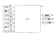
- FIG. 1 is a block diagram of a driving support device
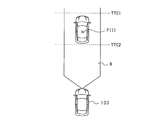
- FIG. 2 is a diagram for explaining an operation area set in front of the own vehicle
- FIG. 3 is a diagram for explaining changes in the course of the own vehicle
- FIG. 4 is a diagram for explaining the update amount map
- FIG. 5 is a diagram illustrating a change in operating conditions based on reliability
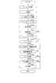
- FIG. 6 is a flowchart illustrating the procedure of PCS control.
- FIG. 7 is a timing chart explaining the limitation of the PCS control according to the present embodiment
- FIG. 8 is a diagram illustrating an update amount map according to the modification
- FIG. 9 is a flowchart illustrating the procedure of PCS control according to the second embodiment.
- the driving support device is installed in a vehicle, and when it is determined that there is a possibility of collision between an object around the own vehicle and the own vehicle, the collision between the own vehicle and the object is avoided or mitigated.
- PCS control pre-crash safety control
- the PCS control corresponds to the driving support process.
- the ECU 10 which is a driving support device, is a computer including a CPU, a ROM, a RAM, an I/O, and the like.
- the CPU realizes each function by executing a program installed in the ROM.
- a millimeter wave radar 21 and an image sensor 22 are connected to the ECU 10 as a sensor device that detects the position of an object located in front of the vehicle.
- the millimeter-wave radar 21 detects the position of the object around the vehicle as the first position by, for example, transmitting a high-frequency signal in the millimeter-wave band and receiving a reflected wave generated by reflecting the millimeter wave on the object. To do.
- the millimeter-wave radar 21 is provided at the front end of the vehicle, and an area within a predetermined detection angle is a detection area where an object can be detected.
- the image sensor 22 includes an image capturing unit that acquires a captured image in front of the vehicle, and detects the position of an object included in the captured image as the second position.
- the image sensor 22 is attached to a predetermined height at the center of the vehicle in the vehicle width direction, and acquires a region that spreads in a predetermined angle range toward the front of the vehicle as a captured image.
- the image sensor 22 extracts the feature points of the object in the captured image, and detects the position and shape of the object using the extracted feature points.
- the imaging unit is, for example, a monocular camera or a compound eye camera.
- the ECU 10 is connected with various sensors 23 to 27 that detect the driving state of the vehicle.
- the accelerator sensor 23 is provided on the accelerator pedal, and detects whether or not the driver has operated the accelerator pedal and the amount of the operation.
- the brake sensor 24 is provided on the brake pedal, and detects whether or not the driver has operated the brake pedal and the amount of the operation.
- the steer sensor 25 detects the steering amount ⁇ associated with the steering operation by the driver.
- the vehicle speed sensor 26 detects the own vehicle speed Vc based on the rotation speed of the wheels.
- the yaw rate sensor 27 detects a yaw rate ⁇ that indicates a change over time in the direction when the vehicle turns.
- An alarm device 31, a brake device 32, and a seat belt device 33 are connected to the ECU 10.
- the alarm device 31 is a speaker or a display installed in the vehicle compartment, and outputs an alarm sound, an alarm message, or the like according to a control command from the ECU 10.
- the brake device 32 applies a braking force to the vehicle.
- the seat belt device 33 is a pretensioner that pulls in a seat belt provided in each seat of the vehicle.
- the ECU 10 acquires an object position P(i), which is the position of an object around the vehicle, based on the detection results of the millimeter wave radar 21 and the image sensor 22.
- the ECU 10 is based on the same object as the first position of the object detected by the millimeter wave radar 21 and the second position of the object detected by the image sensor 22 that are located in the vicinity. Corresponds as.
- the state in which the position of the object is accurately obtained by the millimeter wave radar 21 and the image sensor 22 is referred to as a fusion state.
- the ECU 10 acquires, as an object position P(i), a position where an area set based on the first position and an area set based on the second position intersect with each other with respect to the object determined to be in the fusion state.
- the ECU 10 calculates the relative position of the object with respect to the own vehicle and the relative speed of the object with respect to the own vehicle for each object for which the object position P(i) is acquired.
- the ECU 10 determines whether or not there is a possibility of collision between the own vehicle 100 and the object 200, using the own vehicle course A that is the course of the own vehicle 100 and the object position P(i).
- the ECU 10 calculates the turning radius of the own vehicle 100 using the own vehicle speed Vc detected by the vehicle speed sensor 26 and the yaw rate ⁇ detected by the yaw rate sensor 27, and uses the calculated turning radius as the own vehicle course A. .. It can be considered that the larger the yaw rate ⁇ , the larger the change in the direction of the vehicle 100. Therefore, the ECU 10 calculates the vehicle course A so that the turning radius becomes smaller as the yaw rate ⁇ increases.
- the ECU 10 determines that the own vehicle 100 and the object 200 may collide when the object position P(i) is located on the own vehicle path A.
- the host vehicle course A is linearly calculated, but a target area in which the vehicle width of the host vehicle 100 is taken into consideration may be set as the host vehicle course A.
- the ECU 10 determines whether to activate each of the devices 31 to 33 when determining that the own vehicle 100 and the object 200 may collide with each other. Specifically, as shown in FIG. 2, the ECU 10 determines that the object position P(i) of the object 200 determined to have a possibility of colliding with the own vehicle 100 is within the operation area B defined in front of the own vehicle. When the predicted collision time (hereinafter referred to as TTC) has reached the operation timing associated with each of the devices 31 to 33, each of the devices 31 to 33 is operated.
- TTC predicted collision time
- the operation area B is an area virtually defined in front of the own vehicle, and is, for example, an area smaller than the detection areas of the millimeter wave radar 21 and the image sensor 22.
- TTC is a predicted time until the vehicle 100 and the object 200 collide, and in the present embodiment, the inter-vehicle distance from the vehicle 100 to the object 200 is divided by the relative speed of the object with respect to the vehicle 100. It is calculated by The operation timing is a timing at which the operation of each of the devices 31 to 33 is started, and the TTC at which the operation of each of the devices 31 to 33 is started becomes larger when the operation timing is earlier than when it is late.
- the operation timing is set for each of the alarm device 31, the brake device 32, and the seat belt device 33.
- the operation timing T1 of the alarm device 31 is set to the earliest timing.
- the ECU 10 activates the alarm device 31.
- the warning device 31 notifies the driver of the danger of collision.
- the ECU 10 operates the brake device 32 when the TTC is equal to or less than the operation timing T2 of the brake device 32.
- the operation of the brake device 32 by the ECU 10 includes automatic braking for operating the brake device 32 when the driver is not stepping on the brake pedal and braking force by the brake device 32 when the driver is stepping on the brake pedal. And brake assist to increase.
- the operation timing T2 of the braking device 32 may be provided separately for the brake assist and the automatic braking, or may be the same timing.
- the operation timing of the seat belt device 33 is set to the same value as the operation timing T2 of the brake device 32. For example, with the start of operation of the brake device 32, a preliminary operation of retracting the seat belt by the seat belt device 33 is performed.
- FIG. 3 is a diagram illustrating, as an example, a change in the vehicle course A when the vehicle 100 travels on a curved road that curves to the right.
- the actual travel route of the vehicle 100 is shown by a solid line, and the vehicle course A calculated at each time is shown by a broken line.
- the driver turns the steering wheel to the right to turn the vehicle 100 to the right, and the vehicle 100 turns to the right.
- the yaw rate ⁇ increases.
- the yaw rate ⁇ becomes constant because the direction of the host vehicle 100 becomes constant.
- the yaw rate ⁇ of the own vehicle 100 decreases due to the steering wheel turning back by the driver.
- the turning radius of the host vehicle path A becomes smaller as the yaw rate ⁇ increases.
- the own vehicle course A(t1) calculated at time t1 has a larger turning radius than the traveling route of the own vehicle 100. Therefore, during the period in which the host vehicle 100 travels through the curve entrance, there is a concern that the PCS control may be activated for the object 200A located radially outside the travel route of the host vehicle 100.
- the turning radius of the host vehicle path A becomes smaller as the yaw rate ⁇ decreases.
- the own vehicle course A(t2) calculated at time t2 has a smaller turning radius than the traveling route of the own vehicle 100. Therefore, during the period in which the host vehicle travels through the curve exit, there is a concern that the PCS control may be activated for the object 200B located radially inside the travel route of the host vehicle 100.
- the ECU 10 calculates the reliability E of the vehicle course A using the yaw rate change rate C and the steering speed D that are steering parameters. Then, when it is determined that there is a possibility of collision between the own vehicle 100 and the object 200, the operation of the PCS control is limited based on the calculated reliability E.
- the ECU 10 corresponds to the reliability calculation unit.
- the reliability E is reduced according to the passage of time in the period in which the vehicle 100 is changing the turning state, and the reliability E is reduced in the period in which the vehicle 100 is not changing the turning state. Increase reliability as time goes on.
- the ECU 10 adds the update amount ⁇ E calculated using the yaw rate change rate C and the steering speed D to the previous reliability value E(i ⁇ 1) as shown in the following equation (1).
- the current value E(i) of the reliability is calculated.
- E(i) E(i-1)+ ⁇ E (1)
- the maximum value max (eg, 100) of the reliability E may be used as the previous value E(i-1) of the reliability.
- the ECU 10 calculates the update amount ⁇ E used for updating the previous value E(i-1) of the reliability using the update amount map stored in the ROM.
- FIG. 4 shows an update amount map.
- This update amount map is a map in which the horizontal axis represents the yaw rate change rate C and the vertical axis represents the update amount ⁇ E.
- the update amount ⁇ E has a negative value when the yaw rate change rate C is larger than the reference value SP, and the update amount ⁇ E has a positive value when the yaw rate change rate C is smaller than the reference value SP. Therefore, the relationship between the yaw rate change rate C and the update amount ⁇ E is defined.
- the ECU 10 corresponds to the update amount calculation unit.
- the update amount map has an up region G1 in which a positive update amount ⁇ E is set and a down region G2 in which a negative update amount ⁇ E is set, with a reference value SP that is a predetermined yaw rate change rate C as a boundary. ..
- the reference value SP is set as the yaw rate change rate C when the turning state change of the vehicle 100 starts to occur.
- the positive update amount ⁇ E set in the up region G1 decreases toward the positive side with the limit of zero as the yaw rate change rate C increases.
- the negative update amount ⁇ E set in the down region G2 increases toward the negative side as the yaw rate change rate C increases.
- FIG. 4 shows the up area G1 (SP2) and the down area G2 (SP2) when the reference value is “SP2”.
- the steering speed D fluctuates according to the steering operation by the driver, the steering speed D is more likely to change than the yaw rate change rate C. Therefore, when the steering speed D is low, the possibility that the steering speed D does not reflect the change in the yaw rate ⁇ of the host vehicle 100 is higher than that when the steering speed D is high. Therefore, the ECU 10 calculates the update amount ⁇ E using the update amount map in which the reference value SP is set to a smaller value as the steering speed D is higher.
- the ECU 10 calculates the update amount ⁇ E using the update amount map that is set to the small reference value SP (SP1). Accordingly, in the update amount map, the range of the yaw rate change rate C associated with the down region G2 is widened, so that the update amount ⁇ E tends to have a large negative value.
- the ECU 10 calculates the update amount ⁇ E using the update amount map set to the large reference value SP (SP3). To do. As a result, the range of the yaw rate change rate C associated with the down region G2 is narrowed, and the update amount ⁇ is unlikely to have a large negative value.
- the ECU 10 determines that the previous reliability value E(i-1) has reached the upper limit value and adds the positive update amount ⁇ E to the previous reliability value E(i-1). Maintains the current reliability value E(i) at the upper limit.
- the previous value E(i-1) of the reliability has reached the lower limit value and the negative update amount ⁇ E is added to the previous value E(i-1) of the reliability, The value E(i) is kept at the lower limit.
- the ECU 10 limits the operation of the PCS control according to the calculated reliability E.
- the ECU 10 delays the operation area B, which is the position condition of the object for operating the devices 31 to 33, and the operation timing of the devices 31 to 33, as the operation limit of the PCS control.
- the ECU 10 corresponds to the restriction unit.
- the ECU 10 When the reliability E is smaller than the reliability determination value TH1, the ECU 10 reduces the operation area B in the vehicle width direction with respect to the center in the vehicle width direction as shown in FIG. Is greater than or equal to the reliability determination value TH1, the operation area B is not reduced.
- the ECU 10 when reducing the operation area B in the vehicle width direction, the ECU 10 increases the reduction amount in the vehicle width direction as the reliability E decreases.
- the operation area B is reduced, the object 200 that is subject to the operation condition of operating the devices 31 to 33 among the objects 200 ahead of the own vehicle is restricted more than when the operation area B is not reduced, and thus each device 31 is reduced. ⁇ 33 becomes difficult to operate.
- the ECU 10 When the reliability E is smaller than the reliability determination value TH1, the ECU 10 operates the devices 31 to 33 more than when the reliability E is the reliability determination value TH1 or more, as shown in FIG. 5B. Delay the timing. In this embodiment, when delaying the operation timing of each of the devices 31 to 33, the ECU 10 increases the operation timing delay amount as the reliability E decreases. In the example of FIG. 5B, since the reliability E is smaller than the reliability determination value TH1, the operation timing of the brake device 32 is delayed from TTC2 to TTC3. Delaying the operation timing of each device 31 to 33 makes it difficult for each device 31 to 33 to operate.
- the ECU 10 may not delay the operation timing of each of the devices 31 to 33 using the reliability E after starting the operation of each of the devices 31 to 33. This is to prevent the operation timing of each device 31-33 from being changed and the operation of each device 31-33 from being interrupted.
- step S11 the steering amount ⁇ acquired by the steering sensor 25, the own vehicle speed Vc detected by the vehicle speed sensor 26, and the yaw rate ⁇ detected by the yaw rate sensor 27 are acquired.
- step S12 the vehicle course A is calculated using the vehicle speed Vc and the yaw rate ⁇ acquired in step S11.
- step S13 the yaw rate change rate C and the steering speed D are used to calculate the update amount ⁇ E of the reliability E.
- the yaw rate change rate C is calculated by dividing the absolute value of the current value of the yaw rate ⁇ acquired in step S11 by the previous time value by the control cycle. Further, a value obtained by dividing the absolute value of the current value of the steering amount ⁇ obtained in step S11 by subtracting the previous value by the control cycle is set as the steering speed D.
- the update amount ⁇ E for this time is calculated by referring to the update amount ⁇ E corresponding to the calculated set of the yaw rate change rate C and the steering speed D from the update amount map.
- step S14 a value obtained by adding the update amount ⁇ E calculated in step S13 to the previous value E(i-1) of the reliability E is calculated as the current reliability value E(i).
- step S15 it is determined whether or not the current value E(i) of the reliability calculated in step S14 is smaller than the reliability determination value TH1. If it is determined that the current reliability value E(i) is smaller than the reliability determination value TH1, the process proceeds to step S16, and the operation area B is reduced in the vehicle width direction according to the current reliability value E(i). However, the operation timing of each of the devices 31 to 33 is delayed.
- the restriction flag F indicating that the PCS control is restricted is set to the high state. The restriction flag F is in a high state when the PCS control is restricted, and is in a low state when the PCS control is not restricted.
- step S16 when it is determined in step S16 that the reliability E is equal to or higher than the reliability determination value TH1, the process proceeds to step S17 without changing the operation timing of the operation area B and the devices 31 to 33. In this case, the restriction flag F is set to the low state.
- step S17 it is determined whether the object may collide with the own vehicle by using the own vehicle course A calculated in step S12 and the object position P(i).
- step S17 it is determined whether the object may collide with the own vehicle by using the own vehicle course A calculated in step S12 and the object position P(i).
- the determination in step S17 is negative, the processing of FIG. 6 is once ended.
- step S18 it is decided whether or not the current object position P(i) is within the operation area B. If it is determined that the object position P(i) is not within the operation area B, the processing of FIG. 6 is once ended.
- step S19 it is determined whether or not the current TTC has passed the operation timing of each of the devices 31 to 33.
- the process of FIG. 6 is once ended.
- step S19 If it is determined in step S19 that the current TTC has passed the operation timing of any of the devices 31 to 33, the process proceeds to step S20.
- step S20 PCS control is performed by operating the devices 31 to 33 whose TTC has reached the operation timing. Then, the process of FIG. 6 is once ended.
- FIG. 7A shows the transition of the yaw rate ⁇ of the vehicle 100 according to the steering operation by the driver
- FIG. 7B shows the transition of the yaw rate change rate C
- FIG. 7C shows the transition of the reliability E
- FIG. 7D shows the restriction flag F.
- the yaw rate change rate C is calculated as the absolute value of the change in the yaw rate ⁇ .
- the yaw rate ⁇ increases due to the change in the orientation of the vehicle 100 due to the driver turning the steering wheel. Therefore, during the period from time t11 to t13, the negative update amount ⁇ E is added based on the yaw rate change rate C, so that the reliability E decreases as time passes. Then, at time t12, the reliability E becomes smaller than the reliability determination value TH1, and the restriction flag F changes from the low state to the high state, and the PCS control is restricted.
- the steering angle is kept constant by the driver's operation, so that the orientation of the vehicle 100 is kept constant.
- the yaw rate ⁇ becomes constant due to the constant orientation of the host vehicle 100, and after time t13, the positive update amount ⁇ E is added based on the yaw rate change rate C, so that the reliability increases with time. E increases.
- the reliability E becomes equal to or higher than the reliability determination value TH1
- the limit flag F changes from the high state to the low state, and the limitation of the PCS control is released.
- the yaw rate change rate C is maintained at zero by keeping the orientation of the vehicle 100 constant, so that the reliability E continues to increase.
- the reliability E reaches the maximum value max.
- the yaw rate ⁇ decreases as the driver turns back the steering wheel, and the yaw rate change rate C increases.
- the reliability E decreases with the passage of time. Then, at time t17, the reliability E becomes smaller than the reliability determination value TH1, whereby the restriction flag F changes from the low state to the high state, and the PCS control is restricted.
- the reliability E is increased by adding the positive update amount ⁇ E based on the yaw rate change rate C. Then, at time t19, the reliability E becomes equal to or higher than the reliability determination value TH1, the limit flag F changes from the high state to the low state, and the limitation of the PCS control is released.
- the ECU 10 calculates the reliability E indicating the certainty of the vehicle course A based on the yaw rate change rate C indicating the time change of the yaw rate ⁇ and the steering speed D.
- the execution of the PCS control is restricted based on the calculated reliability E.
- the PCS control is restricted according to the certainty of the course of the host vehicle, so that unnecessary operation of the PCS control can be suppressed.
- the ECU 10 reduces the reliability E according to the passage of time during the period when the turning state change in which the yaw rate change rate C is larger than the reference value SP is occurring, and sets the time during the period when the turning state change is not occurring.
- the reliability E is increased according to the progress of. This makes it possible to properly calculate the reliability E when the vehicle 100 changes between the straight traveling state and the turning state.
- the ECU 10 calculates the update amount ⁇ E of the reliability E based on the yaw rate change rate C in a predetermined cycle, and adds the update amount ⁇ E to the previous value E(i-1) of the reliability to obtain the reliability.
- the current value E(i) of the degree is calculated.
- the update amount ⁇ E is calculated as a negative value
- the update amount ⁇ E is calculated as a positive value.
- the ECU 10 sets the reference value SP to a smaller value as the steering speed D increases.
- the higher the steering speed D the more easily the update amount ⁇ E becomes a negative value, so that the reliability E can be calculated more appropriately.
- the effect of suppressing unnecessary operation of PCS control can be enhanced.
- the update amount ⁇ E associated with each of the up area G1 and the down area G2 may be a constant value.
- FIG. 8 is a diagram showing an update amount map according to this embodiment.
- the update amount map includes the up region G1 in which the positive update amount ⁇ E is set and the down region G2 in which the negative update amount ⁇ E is set.
- the up region G1 the same positive update amount ⁇ E is set regardless of the yaw rate change rate C
- the down region G2 the negative update amount ⁇ E of the same value is set regardless of the yaw rate change rate C. Has been defined.
- the ECU 10 calculates the update amount ⁇ E using the update amount map in which the reference value SP is set to a smaller value as the steering speed D is higher. As a result, the update amount ⁇ E calculated by the ECU 10 easily becomes a negative value.
- the ECU 10 may set the update amount ⁇ E by using either the yaw rate change rate C or the steering speed D as a steering parameter. Even in this case, the larger the value used as the steering parameter in the yaw rate change rate C or the steering speed D, the smaller the update amount ⁇ E is set. Also in the present embodiment described above, the same effect as in the first embodiment can be obtained.
- the ECU 10 further reduces the calculated reliability E when it determines that the vehicle 100 is meandering, thereby strengthening the limitation of the PCS control operation.
- the ECU 10 corresponds to the meandering traveling determination unit and the correction unit.
- step S30 it is determined whether or not the vehicle 100 is meandering.
- the detection history of the yaw rate ⁇ detected by the yaw rate sensor 27 is recorded for each control cycle, and this detection history is used to determine whether or not the vehicle 100 meanders.
- the direction of the yaw rate ⁇ detected in each control cycle does not greatly change to the left and right, so the left and right change width of the yaw rate ⁇ is less than or equal to a predetermined change width determination value. ..
- the host vehicle 100 when the host vehicle 100 is meandering, the direction of the yaw rate ⁇ detected in each control cycle changes greatly to the left and right, so the left and right change width of the yaw rate ⁇ becomes larger than the change width determination value. Therefore, if both the left and right change widths of the yaw rate ⁇ recorded in the detection history are larger than the change width determination value, it may be determined that the host vehicle 100 is in the meandering traveling state. In addition to this, it may be determined whether or not the own vehicle 100 is meandering based on a change in a captured image in front of the own vehicle captured by the image sensor 22.
- step S31 is positively determined, and the process proceeds to step S32.
- step S32 the current reliability value E(i) calculated in step S15 is corrected to the lower side.
- the current reliability value E(i) is corrected to the lower side by multiplying the current reliability value E(i) by the subtraction coefficient ⁇ .
- the subtraction coefficient ⁇ is a value larger than 0 and smaller than 1.
- step S15 When the process goes to step S15 via step S32, the current reliability value E(i) becomes smaller than that when it is determined that the vehicle 100 is not meandering. As a result, the current reliability value E(i) is likely to be smaller than the reliability determination value TH1, and the operation of the PCS control is likely to be restricted. Further, in step S16, the reduction amount of the operation area B in the vehicle width direction and the delay amount of the operation timing of each of the devices 31 to 33 become larger than when the own vehicle 100 is determined not to meander. ..
- step S30 determines whether the vehicle is traveling meandering. If it is determined in step S30 that the vehicle is not traveling meandering, a negative determination is made in step S31, and the process proceeds to step S15.
- the ECU 10 further reduces the reliability E when it determines that the vehicle 100 is meandering.
- the limitation of the operation of the PCS control is further strengthened, so that the unnecessary operation of the PCS control can be appropriately suppressed.
- the ECU 10 does not calculate the current value E(i) of the reliability by updating the previous value E(i-1) of the reliability, but instead of calculating the reliability E by using the steering parameter for each control cycle. May be calculated. In this case, the larger the steering parameter, the smaller the reliability E may be.
- the ECU 10 may determine the possibility of collision between the vehicle and the object by using the object course A2 calculated using the time change of the object position P(i). Specifically, the ECU 10 calculates the object path by acquiring the object position P(i) in time series and approximating the change in the acquired object position P(i). The ECU 10 may determine that the own vehicle 100 and the object 200 may collide with each other when the calculated vehicle course and the calculated object course intersect.
- the ECU 10 may limit the operation of the PCS control by prohibiting the operation of each of the devices 31 to 33 when the reliability E becomes smaller than a predetermined value. In this case, when it is determined in step S15 that the current reliability value E(i) is equal to or less than the operation prohibition determination value lower than the reliability determination value TH1, the operation of each of the devices 31 to 33 is performed in step S16. Should be banned.
- control device and the method described in the present disclosure are provided by a dedicated computer provided by configuring a processor and a memory programmed to execute one or more functions embodied by a computer program, May be realized.
- control unit and the method described in the present disclosure may be realized by a dedicated computer provided by configuring a processor with one or more dedicated hardware logic circuits.
- control unit and the method thereof described in the present disclosure are based on a combination of a processor and a memory programmed to execute one or a plurality of functions and a processor configured by one or more hardware logic circuits. It may be implemented by one or more dedicated computers configured.
- the computer program may be stored in a computer-readable non-transition tangible recording medium as an instruction executed by a computer.
Landscapes
- Engineering & Computer Science (AREA)
- Mechanical Engineering (AREA)
- Transportation (AREA)
- Automation & Control Theory (AREA)
- Physics & Mathematics (AREA)
- General Physics & Mathematics (AREA)
- Regulating Braking Force (AREA)
- Traffic Control Systems (AREA)
- Control Of Driving Devices And Active Controlling Of Vehicle (AREA)
Applications Claiming Priority (2)
| Application Number | Priority Date | Filing Date | Title |
|---|---|---|---|
| JP2018238837A JP7183769B2 (ja) | 2018-12-20 | 2018-12-20 | 運転支援装置 |
| JP2018-238837 | 2018-12-20 |
Publications (1)
| Publication Number | Publication Date |
|---|---|
| WO2020129731A1 true WO2020129731A1 (ja) | 2020-06-25 |
Family
ID=71100832
Family Applications (1)
| Application Number | Title | Priority Date | Filing Date |
|---|---|---|---|
| PCT/JP2019/048088 Ceased WO2020129731A1 (ja) | 2018-12-20 | 2019-12-09 | 運転支援装置 |
Country Status (2)
| Country | Link |
|---|---|
| JP (1) | JP7183769B2 (enExample) |
| WO (1) | WO2020129731A1 (enExample) |
Cited By (2)
| Publication number | Priority date | Publication date | Assignee | Title |
|---|---|---|---|---|
| JPWO2022255005A1 (enExample) * | 2021-05-31 | 2022-12-08 | ||
| US12384360B2 (en) * | 2021-11-26 | 2025-08-12 | Toyota Jidosha Kabushiki Kaisha | Vehicle driving assistance apparatus |
Families Citing this family (1)
| Publication number | Priority date | Publication date | Assignee | Title |
|---|---|---|---|---|
| JP7756523B2 (ja) | 2021-09-13 | 2025-10-20 | Astemo株式会社 | 車両制御装置 |
Citations (5)
| Publication number | Priority date | Publication date | Assignee | Title |
|---|---|---|---|---|
| JP2006119845A (ja) * | 2004-10-20 | 2006-05-11 | Honda Motor Co Ltd | 車両用制御対象判定装置 |
| JP2014191597A (ja) * | 2013-03-27 | 2014-10-06 | Nippon Soken Inc | 運転支援装置 |
| WO2016084501A1 (ja) * | 2014-11-28 | 2016-06-02 | 株式会社デンソー | 予測進路推定装置及び予測進路推定方法 |
| JP2017016272A (ja) * | 2015-06-29 | 2017-01-19 | トヨタ自動車株式会社 | 衝突予測装置 |
| WO2017110703A1 (ja) * | 2015-12-25 | 2017-06-29 | 株式会社デンソー | 運転支援装置及び運転支援方法 |
-
2018
- 2018-12-20 JP JP2018238837A patent/JP7183769B2/ja active Active
-
2019
- 2019-12-09 WO PCT/JP2019/048088 patent/WO2020129731A1/ja not_active Ceased
Patent Citations (5)
| Publication number | Priority date | Publication date | Assignee | Title |
|---|---|---|---|---|
| JP2006119845A (ja) * | 2004-10-20 | 2006-05-11 | Honda Motor Co Ltd | 車両用制御対象判定装置 |
| JP2014191597A (ja) * | 2013-03-27 | 2014-10-06 | Nippon Soken Inc | 運転支援装置 |
| WO2016084501A1 (ja) * | 2014-11-28 | 2016-06-02 | 株式会社デンソー | 予測進路推定装置及び予測進路推定方法 |
| JP2017016272A (ja) * | 2015-06-29 | 2017-01-19 | トヨタ自動車株式会社 | 衝突予測装置 |
| WO2017110703A1 (ja) * | 2015-12-25 | 2017-06-29 | 株式会社デンソー | 運転支援装置及び運転支援方法 |
Cited By (4)
| Publication number | Priority date | Publication date | Assignee | Title |
|---|---|---|---|---|
| JPWO2022255005A1 (enExample) * | 2021-05-31 | 2022-12-08 | ||
| JP7814385B2 (ja) | 2021-05-31 | 2026-02-16 | パナソニック インテレクチュアル プロパティ コーポレーション オブ アメリカ | 監視システム、監視方法、監視装置および機能制限装置 |
| US12384360B2 (en) * | 2021-11-26 | 2025-08-12 | Toyota Jidosha Kabushiki Kaisha | Vehicle driving assistance apparatus |
| US20250346224A1 (en) * | 2021-11-26 | 2025-11-13 | Toyota Jidosha Kabushiki Kaisha | Vehicle driving assistance apparatus |
Also Published As
| Publication number | Publication date |
|---|---|
| JP2020100230A (ja) | 2020-07-02 |
| JP7183769B2 (ja) | 2022-12-06 |
Similar Documents
| Publication | Publication Date | Title |
|---|---|---|
| US10854081B2 (en) | Driving assistance device and driving assistance method | |
| JP6491596B2 (ja) | 車両制御装置及び車両制御方法 | |
| US12005894B2 (en) | Vehicle pre-collision detection and response device | |
| JP6036839B2 (ja) | 運転支援装置及び運転支援方法 | |
| US10967857B2 (en) | Driving support device and driving support method | |
| CN105339228B (zh) | 静止目标识别的自适应巡航控制 | |
| US10665107B2 (en) | Moving object control apparatus and method of controlling moving object | |
| US20160193999A1 (en) | Vehicle travel safety device, vehicle travel safety method, and vehicle travel safety program | |
| CN111712416B (zh) | 汽车车道变更控制方法及汽车车道变更控制装置 | |
| WO2016158223A1 (ja) | 運転支援装置及び運転支援方法 | |
| JP6740970B2 (ja) | 走行支援装置 | |
| US10723350B2 (en) | Driving assistance apparatus and driving assistance method | |
| WO2017111135A1 (ja) | 走行支援装置及び走行支援方法 | |
| WO2018101208A1 (ja) | 走行制御装置 | |
| JP6693380B2 (ja) | 車両制御装置 | |
| JP6347242B2 (ja) | 車両の制御装置 | |
| JP7183769B2 (ja) | 運転支援装置 | |
| JP2022147629A (ja) | 運転支援装置 | |
| JP6627093B2 (ja) | 車両制御装置、車両制御方法、及び、車両制御用プログラム | |
| US11724694B2 (en) | Traveling assistance apparatus | |
| KR102413579B1 (ko) | 운전자 편의 장치 및 그의 타겟 추정 방법 | |
| JP2019219855A (ja) | 衝突回避支援装置 | |
| US12434673B2 (en) | Driving support apparatus, driving support method, and non-transitory computer-readable storage medium |
Legal Events
| Date | Code | Title | Description |
|---|---|---|---|
| 121 | Ep: the epo has been informed by wipo that ep was designated in this application |
Ref document number: 19898791 Country of ref document: EP Kind code of ref document: A1 |
|
| NENP | Non-entry into the national phase |
Ref country code: DE |
|
| 122 | Ep: pct application non-entry in european phase |
Ref document number: 19898791 Country of ref document: EP Kind code of ref document: A1 |