WO2020129665A1 - コネクタ構造体 - Google Patents
コネクタ構造体 Download PDFInfo
- Publication number
- WO2020129665A1 WO2020129665A1 PCT/JP2019/047581 JP2019047581W WO2020129665A1 WO 2020129665 A1 WO2020129665 A1 WO 2020129665A1 JP 2019047581 W JP2019047581 W JP 2019047581W WO 2020129665 A1 WO2020129665 A1 WO 2020129665A1
- Authority
- WO
- WIPO (PCT)
- Prior art keywords
- outer conductor
- dielectric
- shield
- wire
- crimping
- Prior art date
- Legal status (The legal status is an assumption and is not a legal conclusion. Google has not performed a legal analysis and makes no representation as to the accuracy of the status listed.)
- Ceased
Links
Images


Classifications
-
- H—ELECTRICITY
- H01—ELECTRIC ELEMENTS
- H01R—ELECTRICALLY-CONDUCTIVE CONNECTIONS; STRUCTURAL ASSOCIATIONS OF A PLURALITY OF MUTUALLY-INSULATED ELECTRICAL CONNECTING ELEMENTS; COUPLING DEVICES; CURRENT COLLECTORS
- H01R13/00—Details of coupling devices of the kinds covered by groups H01R12/70 or H01R24/00 - H01R33/00
- H01R13/648—Protective earth or shield arrangements on coupling devices, e.g. anti-static shielding
- H01R13/658—High frequency shielding arrangements, e.g. against EMI [Electro-Magnetic Interference] or EMP [Electro-Magnetic Pulse]
- H01R13/6591—Specific features or arrangements of connection of shield to conductive members
- H01R13/6592—Specific features or arrangements of connection of shield to conductive members the conductive member being a shielded cable
-
- H—ELECTRICITY
- H01—ELECTRIC ELEMENTS
- H01R—ELECTRICALLY-CONDUCTIVE CONNECTIONS; STRUCTURAL ASSOCIATIONS OF A PLURALITY OF MUTUALLY-INSULATED ELECTRICAL CONNECTING ELEMENTS; COUPLING DEVICES; CURRENT COLLECTORS
- H01R4/00—Electrically-conductive connections between two or more conductive members in direct contact, i.e. touching one another; Means for effecting or maintaining such contact; Electrically-conductive connections having two or more spaced connecting locations for conductors and using contact members penetrating insulation
- H01R4/10—Electrically-conductive connections between two or more conductive members in direct contact, i.e. touching one another; Means for effecting or maintaining such contact; Electrically-conductive connections having two or more spaced connecting locations for conductors and using contact members penetrating insulation effected solely by twisting, wrapping, bending, crimping, or other permanent deformation
- H01R4/18—Electrically-conductive connections between two or more conductive members in direct contact, i.e. touching one another; Means for effecting or maintaining such contact; Electrically-conductive connections having two or more spaced connecting locations for conductors and using contact members penetrating insulation effected solely by twisting, wrapping, bending, crimping, or other permanent deformation by crimping
- H01R4/183—Electrically-conductive connections between two or more conductive members in direct contact, i.e. touching one another; Means for effecting or maintaining such contact; Electrically-conductive connections having two or more spaced connecting locations for conductors and using contact members penetrating insulation effected solely by twisting, wrapping, bending, crimping, or other permanent deformation by crimping for cylindrical elongated bodies, e.g. cables having circular cross-section
- H01R4/184—Electrically-conductive connections between two or more conductive members in direct contact, i.e. touching one another; Means for effecting or maintaining such contact; Electrically-conductive connections having two or more spaced connecting locations for conductors and using contact members penetrating insulation effected solely by twisting, wrapping, bending, crimping, or other permanent deformation by crimping for cylindrical elongated bodies, e.g. cables having circular cross-section comprising a U-shaped wire-receiving portion
-
- H—ELECTRICITY
- H01—ELECTRIC ELEMENTS
- H01R—ELECTRICALLY-CONDUCTIVE CONNECTIONS; STRUCTURAL ASSOCIATIONS OF A PLURALITY OF MUTUALLY-INSULATED ELECTRICAL CONNECTING ELEMENTS; COUPLING DEVICES; CURRENT COLLECTORS
- H01R13/00—Details of coupling devices of the kinds covered by groups H01R12/70 or H01R24/00 - H01R33/00
- H01R13/646—Details of coupling devices of the kinds covered by groups H01R12/70 or H01R24/00 - H01R33/00 specially adapted for high-frequency, e.g. structures providing an impedance match or phase match
- H01R13/6473—Impedance matching
-
- H—ELECTRICITY
- H01—ELECTRIC ELEMENTS
- H01R—ELECTRICALLY-CONDUCTIVE CONNECTIONS; STRUCTURAL ASSOCIATIONS OF A PLURALITY OF MUTUALLY-INSULATED ELECTRICAL CONNECTING ELEMENTS; COUPLING DEVICES; CURRENT COLLECTORS
- H01R13/00—Details of coupling devices of the kinds covered by groups H01R12/70 or H01R24/00 - H01R33/00
- H01R13/648—Protective earth or shield arrangements on coupling devices, e.g. anti-static shielding
- H01R13/658—High frequency shielding arrangements, e.g. against EMI [Electro-Magnetic Interference] or EMP [Electro-Magnetic Pulse]
- H01R13/6581—Shield structure
- H01R13/6582—Shield structure with resilient means for engaging mating connector
-
- H—ELECTRICITY
- H01—ELECTRIC ELEMENTS
- H01R—ELECTRICALLY-CONDUCTIVE CONNECTIONS; STRUCTURAL ASSOCIATIONS OF A PLURALITY OF MUTUALLY-INSULATED ELECTRICAL CONNECTING ELEMENTS; COUPLING DEVICES; CURRENT COLLECTORS
- H01R13/00—Details of coupling devices of the kinds covered by groups H01R12/70 or H01R24/00 - H01R33/00
- H01R13/648—Protective earth or shield arrangements on coupling devices, e.g. anti-static shielding
- H01R13/658—High frequency shielding arrangements, e.g. against EMI [Electro-Magnetic Interference] or EMP [Electro-Magnetic Pulse]
- H01R13/6591—Specific features or arrangements of connection of shield to conductive members
- H01R13/65912—Specific features or arrangements of connection of shield to conductive members for shielded multiconductor cable
- H01R13/65914—Connection of shield to additional grounding conductors
-
- H—ELECTRICITY
- H01—ELECTRIC ELEMENTS
- H01R—ELECTRICALLY-CONDUCTIVE CONNECTIONS; STRUCTURAL ASSOCIATIONS OF A PLURALITY OF MUTUALLY-INSULATED ELECTRICAL CONNECTING ELEMENTS; COUPLING DEVICES; CURRENT COLLECTORS
- H01R4/00—Electrically-conductive connections between two or more conductive members in direct contact, i.e. touching one another; Means for effecting or maintaining such contact; Electrically-conductive connections having two or more spaced connecting locations for conductors and using contact members penetrating insulation
- H01R4/10—Electrically-conductive connections between two or more conductive members in direct contact, i.e. touching one another; Means for effecting or maintaining such contact; Electrically-conductive connections having two or more spaced connecting locations for conductors and using contact members penetrating insulation effected solely by twisting, wrapping, bending, crimping, or other permanent deformation
- H01R4/18—Electrically-conductive connections between two or more conductive members in direct contact, i.e. touching one another; Means for effecting or maintaining such contact; Electrically-conductive connections having two or more spaced connecting locations for conductors and using contact members penetrating insulation effected solely by twisting, wrapping, bending, crimping, or other permanent deformation by crimping
- H01R4/20—Electrically-conductive connections between two or more conductive members in direct contact, i.e. touching one another; Means for effecting or maintaining such contact; Electrically-conductive connections having two or more spaced connecting locations for conductors and using contact members penetrating insulation effected solely by twisting, wrapping, bending, crimping, or other permanent deformation by crimping using a crimping sleeve
Definitions
- the technology disclosed in the present specification relates to a connector structure in which a connector is connected to a terminal of a shielded electric wire.
- This connector structure includes a shielded electric wire in which a core wire, an insulating coating, a shield part, and a sheath are laminated from inside to outside, an inner conductor connected to the core wire, and an insulating dielectric material surrounding the outer circumference of the inner conductor. And an outer conductor that is crimped to the outer circumference of the shield part and surrounds the covered electric wire and the dielectric.
- the covered electric wire exposed from the sheath and the shield portion of the covered electric wire is electromagnetically shielded by being surrounded by the outer conductor.
- the portion of the outer conductor corresponding to the covered electric wire exposed from the shield is drawn inward in the radial direction of the outer conductor.
- the technique disclosed in the present specification has been completed based on the above circumstances, and an object thereof is to provide a connector structure in which a change in characteristic impedance is suppressed while suppressing an increase in size. To do.
- a technique disclosed in the present specification is a connector structure, in which a shielded electric wire in which an outer circumference of a coated wire in which an outer circumference of a core wire is surrounded by an insulating coating is surrounded by a shield portion, and a core wire connected to the core wire
- An inner conductor having a connecting portion and a connecting portion that is connected to the counterpart terminal and is connected to the core wire connecting portion, at least an insulating dielectric that surrounds the outer periphery of the connecting portion of the inner conductor, and the shield portion.
- the corresponding portion is formed with a protrusion in which the inner surface of the outer conductor protrudes from the other portion inward in the radial direction of the outer conductor, and the outer surface of the outer conductor has the diameter of the outer conductor. It has not collapsed inward.
- the inner surface of the outer conductor can be brought close to the covered electric wire without drawing the outer conductor. As a result, it is possible to prevent the characteristic impedance of the covered electric wire from changing without increasing the size of the outer conductor.
- the inner surface of the tubular portion can be brought close to the covered electric wire by a simple processing method of folding back the protruding portion, so that the manufacturing cost of the connector structure can be reduced.
- the outer conductor has a shield connecting portion that is crimped from the outside to the shield portion, and a dielectric crimping portion that is crimped from the outside to at least a part of the dielectric body, and the shield connecting portion and the dielectric body.
- a rear outer conductor having a rear cylindrical portion surrounding the covered electric wire between the crimping portion and a front cylindrical portion surrounding the dielectric, and a rear outer conductor crimping crimping from the outside to the dielectric crimping portion.
- a front outer conductor having a portion, and the protruding portion is formed on the rear tubular portion.
- the rear outer conductor and the front outer conductor can be connected to each other without applying heat, so that it is possible to suppress the occurrence of a defect in the dielectric due to heat.
- the outer conductor has a front cylindrical portion that surrounds the dielectric, and has a front outer conductor that has a dielectric locking portion that locks at least a part of the dielectric, and is crimped to the shield portion from the outside. It has a shield connecting portion and at least a front outer conductor crimping portion that is crimped from the outside of the dielectric locking portion, and surrounds the covered electric wire between the shield connecting portion and the front outer conductor crimping portion.
- the rear outer conductor having a rear cylindrical portion and the protruding portion are formed on the rear cylindrical portion.
- the rear outer conductor and the front outer conductor can be connected to each other without applying heat, so that it is possible to suppress the occurrence of a defect in the dielectric due to heat.
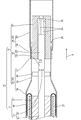
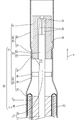
- Sectional drawing which shows the female connector structure which concerns on Embodiment 1.
- Sectional drawing which shows the process of fitting a sleeve on a shield electric wire.
- Sectional drawing which shows the process of peeling the sheath of a shielded electric wire.
- Sectional drawing which shows the process of folding back a braided wire on a sleeve
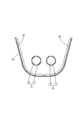
- a perspective view showing a process of inserting a female terminal into a dielectric.
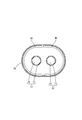
- Perspective view showing a state in which a female terminal is inserted into a dielectric
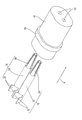
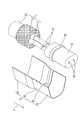
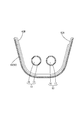
- FIG. 3 is a perspective view showing a process of crimping the rear outer conductor with the protruding portion folded back to the braided wire and the dielectric.
- Sectional drawing which shows the process of crimping
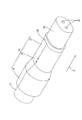
- Perspective view showing a state in which the rear outer conductor is crimped
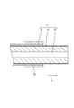
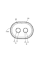
- Sectional drawing which shows a covered electric wire and a protrusion part
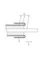
- Sectional drawing which shows the female connector structure which concerns on Embodiment 2.
- Sectional drawing which shows the protrusion part which concerns on Embodiment 3.
- the female connector structure 10 has a female connector 12 connected to the end of a shielded electric wire 11.
- the female connector 12 includes a female terminal 18 (an example of an inner conductor), a dielectric 19, a rear outer conductor 33, and a front outer conductor 34.
- the direction in which the shielded electric wire 11 extends is the front.
- only some of the members may be denoted by the reference numerals, and other members may not be denoted by the reference numerals.
- Shielded wire 11 As shown in FIG. 7, in the shielded electric wire 11, a plurality (two in the present embodiment) of the covered electric wires 13 are surrounded by a braided wire 14 (an example of a shield part) made of a fine metal wire, and the braided wire 14 is surrounded. Is surrounded by a sheath 15 made of an insulating material.
- Each covered electric wire 13 includes a core wire 16 and an insulating coating 17 surrounding the outer circumference of the core wire 16.
- any metal such as copper, copper alloy, aluminum, aluminum alloy, or the like can be selected as necessary.
- the core wire 16 may be made of one metal element wire, or may be made of a stranded wire in which a plurality of metal element wires are twisted together.
- the insulating coating 17 and the sheath 15 are made of insulating synthetic resin.
- the end of the shielded electric wire 11 is subjected to a terminal treatment such as peeling, and the respective ends of the core wire 16, the insulation coating 17, and the braided wire 14 are exposed.
- the female connector 12 includes a female terminal 18 (an example of an inner conductor), an insulating dielectric 19 that surrounds the outer periphery of the female terminal 18, and an outer conductor 20 that surrounds the outer periphery of the dielectric 19.
- the outer conductor 20 has a rear outer conductor 33 and a front outer conductor 34 electrically connected to the front end portion of the rear outer conductor 33.
- the female terminal 18 is formed by pressing a metal plate material into a predetermined shape.
- the metal forming the female terminal 18 any metal such as copper, copper alloy, aluminum, and aluminum alloy can be selected as necessary.
- the female terminal 18 is connected to the end of each covered electric wire 13.
- the female terminal 18 is connected to the wire barrel 22 (an example of a core wire connecting portion) that is crimped so as to be wound around the outer periphery of the core wire 16, and the connecting tubular portion 23 that is connected to the front of the wire barrel 22 and into which a mating terminal (not shown) is inserted. (An example of a connecting portion).
- a plurality of elastic contact pieces 24 extending in the front-rear direction are provided in the connecting tubular portion 23 by forming a plurality of slits extending rearward from the front end portion of the connecting tubular portion 23.
- the plurality of elastic contact pieces 24 are reduced in diameter toward the front, and are elastically deformable in the radial direction of the connecting tubular portion 23.
- the braided wire 14 is formed by braiding a plurality of thin metal wires in a tubular shape. A portion of the braided wire 14 exposed from the end of the sheath 15 is folded back to the end of the sheath 15 and overlapped on the outer side of a sleeve 27 described later.
- annular sleeve 27 is fitted on the outside of the end of the sheath 15, and the braided wire 14 is overlaid on the outside of the sleeve 27 as described above.
- the sleeve 27 according to the present embodiment is formed in a substantially annular shape by crimping an elongated metal plate material so as to wind around the outer periphery of the sheath 15.
- Dielectric 19 As shown in FIG. 1, the periphery of the connecting cylinder portion 23 of the female terminal 18 is surrounded by the dielectric material 19.
- the dielectric 19 is formed by injection molding an insulating synthetic resin.
- a wire barrel 22 projects rearward from the rear end of the dielectric 19.
- the dielectric 19 as a whole extends in the front-rear direction and has a cross-sectional shape that is an elongated oval shape in the left-right direction.
- the dielectric 19 is opened in the front-rear direction, and a plurality of (two in the present embodiment) cavities 32 in which the connection tubular portions 23 of the female terminals 18 are respectively housed are formed side by side in the left-right direction. ..
- a mating terminal is inserted through the front opening of the cavity 32.
- the wire barrel 22 is led out from the opening on the rear side of the cavity 32.
- a flange 28 protruding outward in the radial direction of the dielectric 19 is formed in a portion of the dielectric 19 approximately one-third from the rear end in the front-rear direction.
- Rear outer conductor 33 As shown in FIGS. 1 and 7, the rear outer conductor 33 is formed by pressing a metal plate material into a predetermined shape. As the metal forming the rear outer conductor 33, any metal such as copper, copper alloy, aluminum, and aluminum alloy can be selected as necessary.
- the rear outer conductor 33 is connected to the shield connecting portion 35 that is crimped from the outside to the braided wire 14 folded back on the sleeve 27, and is connected to the front of the shield connecting portion 35, and the outer circumference of the covered electric wire 13 exposed from the braided wire 14
- the rear outer conductor 33 is crimped to the outer periphery of the braided wire 14 and is crimped from the outside to a position near the rear end of the dielectric 19 in a form in which the left and right edges are attached to each other.
- the dielectric pressure-bonding portion 37 is pressure-bonded to a portion of the dielectric 19 that is behind the flange 28. The front end of the dielectric pressure-bonding portion 37 comes into contact with the flange 28 from the rear, whereby the rear outer conductor 33 and the dielectric 19 can be positioned in the front-rear direction.
- the outer diameter dimension of the shield connecting portion 35 is larger than that of the dielectric crimping portion 37. Is also set large.
- the rear tubular portion 36 which is located between the shield connecting portion 35 and the dielectric pressure-bonding portion 37, is formed in a shape in which the diameter is reduced toward the front.
- a projecting portion 40 that projects inward in the radial direction of the rear tubular portion from the inner wall of the rear tubular portion 36 is formed in the rear tubular portion 36 at a position corresponding to the covered electric wire 13 exposed forward from the braided wire 14. ..
- the protruding portion 40 faces at least a part of the covered electric wire 13 exposed from the braided wire 14.
- the protruding portion 40 may face all portions of the covered electric wire 13 exposed from the braided wire 14.
- the protruding portion 40 is formed by protruding from the left and right side edges of the rear tubular portion 36 and then folded back along the inner surface of the rear tubular portion 36.
- the front outer conductor 34 is formed by pressing a metal plate material into a predetermined shape.
- any metal such as copper, copper alloy, aluminum, and aluminum alloy can be selected as necessary.
- the front outer conductor 34 is connected to the front tubular portion 38 that surrounds the outer periphery of the dielectric body 19, and the front of the front tubular portion 38.
- the front outer conductor 34 is formed on the dielectric crimping portion 37 that is crimped to a portion near the rear end portion of the dielectric material 19. It has an outer conductor crimping portion 39 after crimping.
- the front end portion of the front tubular portion 38 is formed to extend forward of the front end portion of the dielectric body 19.
- the rear outer conductor crimp portion 39 is crimped onto the dielectric crimp portion 37 of the rear outer conductor 33 behind the flange 28 of the dielectric material 19.
- the diameter of the rear outer conductor crimping portion 39 is smaller than that of the front cylindrical portion 38.
- the sleeve 27 is fitted on the outer circumference of the sheath 15 at a position retracted from the end portion of the shielded electric wire 11 by a predetermined length dimension.
- the braided wire 14 is exposed from the sheath 15 by peeling off a portion of the sheath 15 that is in front of the front end portion of the sleeve 27.
- the braided wire 14 is cut into a predetermined length, and the covered electric wire 13 is exposed from the braided wire 14.
- the sleeve 27 serves as a mark for the position where the sheath 15 is peeled off.
- the braided wire 14 is folded back and overlapped on the sleeve 27.
- the insulation coating 17 is peeled off with a predetermined length to expose the core wire 16 from the insulation coating 17.
- the female terminal 18 is inserted into the cavity 32 of the dielectric 19 from the rear.
- the wire barrel 22 of the female terminal 18 projects rearward from the rear end of the dielectric 19.
- the female terminal 18 is connected to the end of the coated electric wire 13 by crimping the wire barrel 22 to the outer periphery of the core wire 16 exposed from the front end of the insulating coating 17 (see FIG. 7 ).
- the protruding portions 40 protruding from the left and right edges of the rear tubular portion 36 provided on the rear outer conductor 33 are folded back along the inner surface of the rear tubular portion 36.
- the shield connecting portion 35 of the rear outer conductor 33 is crimped from the outside to the braided wire 14 folded back on the sleeve 27. Further, the dielectric pressure-bonding portion 37 of the rear outer conductor 33 is pressure-bonded to the portion of the dielectric 19 rearward of the flange 28 from the outside.
- the step of crimping the shield connecting portion 35 to the braided wire 14 and the step of crimping the dielectric crimping portion 37 to the dielectric 19 may be performed in the same step. Further, the step of crimping the shield connecting portion 35 to the braided wire 14 and the step of crimping the dielectric crimping portion 37 to the dielectric 19 may be performed separately.
- the shield crimp portion 35 may be crimped to the braided wire 14 first, and then the dielectric crimp portion 37 may be crimped to the dielectric material 19. Alternatively, the dielectric crimp portion 37 may be crimped to the dielectric material 19 and then the shield connection may be performed.
- the portion 35 may be crimped to the braided wire 14.
- the front outer conductor 34 is formed into a tubular shape. As shown in FIG. 1, the cylindrical front outer conductor 34 is assembled to the dielectric 19 from the front of the dielectric 19. The rear outer conductor crimping portion 39 of the front outer conductor 34 is crimped to the dielectric 19 and then crimped to the dielectric crimping portion 37 of the outer conductor 33 from the outside. Through the above steps, the female connector structure 10 is completed (see FIG. 1).
- the female connector structure 10 is connected to the core wire 16 and the shielded electric wire 11 in which the outer circumference of the covered wire 13 formed by surrounding the outer circumference of the core wire 16 with the insulating coating 17 is surrounded by the braided wire 14.
- a female terminal 18 having a wire barrel 22 and a connecting tubular portion 23 connected to the other terminal in a continuous manner with the wire barrel 22, and an insulating dielectric that surrounds at least the outer periphery of the connecting tubular portion 23 of the female terminal 18.
- the braided wire A portion corresponding to the covered electric wire 13 exposed from 14 is formed with a protrusion 40 in which the inner surface of the outer conductor 20 protrudes from the other portion inward in the radial direction of the outer conductor 20, and the outer conductor 20.
- the outer surface of is not depressed inward in the radial direction of the outer conductor 20.
- the inner surface of the outer conductor 20 can be brought closer to the covered electric wire 13 without drawing the outer conductor 20. As a result, it is possible to prevent the characteristic impedance of the covered electric wire 13 from changing without increasing the size of the outer conductor 20.
- the protruding portion 40 is formed so as to protrude from the end edge of the outer conductor 20 and is folded back so as to overlap with the inner surface of the outer conductor 20. body.
- the inner surface of the outer conductor 20 can be brought closer to the covered electric wire 13 by a simple processing method in which the protruding portion 40 protruding from the end edge of the outer conductor 20 is folded back. Manufacturing cost can be reduced.
- the outer conductor 20 has the shield connecting portion 35 that is crimped to the braided wire 14 from the outside, and the dielectric crimping portion 37 that is crimped from the outside to at least a part of the dielectric 19.
- a rear outer conductor 33 having a rear tubular portion 36 surrounding the covered electric wire 13 and a front tubular portion 38 surrounding the dielectric 19 are provided between the shield connecting portion 35 and the dielectric pressure-bonding portion 37.
- a front outer conductor 34 having a rear outer conductor crimping portion 39 that is crimped from the outside to the body crimping portion 37, and a projecting portion 40 is formed on the rear tubular portion 36.
- the rear outer conductor 33 and the front outer conductor 34 do not have to be welded, the rear outer conductor 33 and the front outer conductor 34 can be connected without applying heat. As a result, it is possible to prevent the dielectric 19 from being defective due to heat.
- the front outer conductor 34 has a dielectric locking portion 51 that is connected to the rear of the front tubular portion 38 and that has a diameter smaller than that of the front tubular portion 38.
- the inner diameter dimension of the front tubular portion 38 is set to be the same as or slightly larger than the outer diameter dimension of the flange 28.
- the front end portion of the front tubular portion 38 is formed to extend forward of the front end portion of the dielectric body 19.
- the inner wall surface of the dielectric locking portion 51 is locked to the flange 28 of the dielectric 19 and a portion behind the flange 28.
- the rear outer conductor 33 is connected to the front of the rear tubular portion 36 and is crimped from the outside to the dielectric locking portion 51 locked at a position near the rear end of the dielectric 19. It has a crimp portion 52.
- the protruding portion 40 is formed on the rear tubular portion 36.
- the rear outer conductor 33 is crimped to the outer periphery of the braided wire 14 in a form in which the left and right edges are attached to each other, and is crimped from the outside to a position near the rear end of the dielectric locking portion 51.
- the front outer conductor crimping portion 52 is crimped to a portion of the dielectric 19 that is behind the flange 28.
- the front outer conductor crimping portion 52 is crimped from the outside of the dielectric locking portion 51, whereby the front outer conductor crimping portion 52 and the dielectric locking portion 51 are fixed to the dielectric 19, and the front outer The conductor 34 and the rear outer conductor 33 are electrically connected.
- the outer diameter dimension of the shield connecting portion 35 is the outer diameter dimension of the front outer conductor crimping portion 52. Is set larger than.
- the outer conductor 20 has the front cylindrical portion 38 that surrounds the dielectric 19, and the front outer conductor 34 that has the dielectric locking portion 51 that locks at least a part of the dielectric 19.
- the braided wire 14 has a shield connecting portion 35 that is crimped from the outside, and at least a front outer conductor crimping portion 52 that is crimped from the outside of the dielectric locking portion 51.
- the shield connecting portion 35 and the front outer conductor are crimped.
- a rear outer conductor 33 having a rear tube portion 36 surrounding the covered electric wire 13 is provided between the portion 52 and the rear outer conductor 33, and a protrusion 40 is formed on the rear tube portion 36.
- the rear outer conductor 33 and the front outer conductor 34 do not have to be welded, the rear outer conductor 33 and the front outer conductor 34 can be connected without applying heat. As a result, it is possible to prevent the dielectric 19 from being defective due to heat.
- the protruding portion 62A that projects from one of the left and right side edges of the rear tubular portion 61 is folded back along the inner wall surface of the rear tubular portion 61. ..
- a protruding portion 62B protruding from the other of the left and right side edges of the rear tubular portion 61 is folded back so as to overlap the protruding portion 62A.
- the inward protruding dimension of the protruding portions 62A and 62B from the rear tubular portion 61 is twice the thickness dimension of the rear tubular portion 61.
- the inner surface of the rear tubular portion 61 can be brought closer to the covered electric wire 13, and thus the characteristic impedance of the covered electric wire 13 can be suppressed from changing.
- the shielded electric wire may have one or three or more covered electric wires.
- the shield layer is not limited to the braided wire 14, and any material such as a metal foil or a resin tape to which a metal foil is attached can be appropriately selected.
- the sheath may be omitted.
- the crimping member formed separately from the rear outer conductor 33 is crimped to the shield connecting portion from outside the shield connecting portion while the shield connecting portion 35 is fitted on the outer periphery of the braided wire 14.
- the braided wire 14 and the shield connecting portion 35 may be electrically connected.
- the connector structure may be a male terminal structure including male terminals.
- the protruding portion may be configured such that only a part of the metal plate material forming the rear outer conductor is formed so as to protrude inward in the radial direction.
- the protruding portion 62A and the protruding portion 62B overlap each other, but the present invention is not limited to this, and three or more protruding portions may overlap each other.
- Female connector structure (an example of connector structure) 11: Shielded wire 12: Female connector 13: Coated wire 14: Braided wire (an example of shield part) 15: sheath 16: core wire 17: insulating coating 18: female terminal (an example of inner conductor) 19: Dielectric 20: Outer conductor 22: Wire barrel (an example of core wire connection part) 23: Connection tube part (an example of connection part) 24: Elastic contact piece 27: Sleeve 28: Flange 32: Cavity 33, 60: Rear outer conductor 34: Front outer conductor 35: Shield connection part 36, 61: Rear cylinder part 37: Dielectric pressure bonding part 38: Front cylinder part 39 : Rear outer conductor crimping portion 40, 62A, 62B: Projection portion 51: Dielectric locking portion 52: Front outer conductor crimping portion
Landscapes
- Details Of Connecting Devices For Male And Female Coupling (AREA)
- Coupling Device And Connection With Printed Circuit (AREA)
Priority Applications (2)
| Application Number | Priority Date | Filing Date | Title |
|---|---|---|---|
| US17/312,914 US11749953B2 (en) | 2018-12-21 | 2019-12-05 | Connector structure |
| CN201980083350.XA CN113196584B (zh) | 2018-12-21 | 2019-12-05 | 连接器结构体 |
Applications Claiming Priority (2)
| Application Number | Priority Date | Filing Date | Title |
|---|---|---|---|
| JP2018239932A JP7103204B2 (ja) | 2018-12-21 | 2018-12-21 | コネクタ構造体 |
| JP2018-239932 | 2018-12-21 |
Publications (1)
| Publication Number | Publication Date |
|---|---|
| WO2020129665A1 true WO2020129665A1 (ja) | 2020-06-25 |
Family
ID=71100822
Family Applications (1)
| Application Number | Title | Priority Date | Filing Date |
|---|---|---|---|
| PCT/JP2019/047581 Ceased WO2020129665A1 (ja) | 2018-12-21 | 2019-12-05 | コネクタ構造体 |
Country Status (4)
| Country | Link |
|---|---|
| US (1) | US11749953B2 (enExample) |
| JP (1) | JP7103204B2 (enExample) |
| CN (1) | CN113196584B (enExample) |
| WO (1) | WO2020129665A1 (enExample) |
Cited By (2)
| Publication number | Priority date | Publication date | Assignee | Title |
|---|---|---|---|---|
| EP4075603A1 (en) * | 2021-04-15 | 2022-10-19 | TE Connectivity Germany GmbH | Electrical crimp ferrule, method for ferrule mounting and method for assembling an electrical connecting device |
| WO2024084912A1 (ja) * | 2022-10-18 | 2024-04-25 | 住友電装株式会社 | シールド電線、及びコネクタ |
Families Citing this family (4)
| Publication number | Priority date | Publication date | Assignee | Title |
|---|---|---|---|---|
| DE102021117039A1 (de) * | 2021-07-01 | 2023-01-05 | Te Connectivity Germany Gmbh | Elektrische Mehradernkabel-Crimpferrule sowie Crimpverfahren |
| JP2025164562A (ja) * | 2024-04-19 | 2025-10-30 | イリソ電子工業株式会社 | 端子ユニット及びこれを備えるコネクタ |
| JP2025164560A (ja) * | 2024-04-19 | 2025-10-30 | イリソ電子工業株式会社 | 端子ユニット及びこれを備えるコネクタ |
| JP2025164561A (ja) * | 2024-04-19 | 2025-10-30 | イリソ電子工業株式会社 | 端子ユニット及びこれを備えるコネクタ |
Citations (2)
| Publication number | Priority date | Publication date | Assignee | Title |
|---|---|---|---|---|
| JPH0269484U (enExample) * | 1988-11-15 | 1990-05-25 | ||
| US20120252265A1 (en) * | 2011-03-31 | 2012-10-04 | John Mezzalingua Associates, Inc. | Connector assembly for corrugated coaxial cable |
Family Cites Families (30)
| Publication number | Priority date | Publication date | Assignee | Title |
|---|---|---|---|---|
| US4611878A (en) * | 1983-01-31 | 1986-09-16 | Amp Incorporated | Electrical plug connector |
| US5180316A (en) * | 1991-03-25 | 1993-01-19 | Molex Incorporated | Shielded electrical connector |
| JP3365550B2 (ja) * | 1999-05-07 | 2003-01-14 | 住友電装株式会社 | シールド端子 |
| JP2003297493A (ja) * | 2002-04-05 | 2003-10-17 | Auto Network Gijutsu Kenkyusho:Kk | 同軸コネクタ |
| FR2877150B1 (fr) * | 2004-10-27 | 2007-01-19 | Radiall Sa | Procede de montage d'un connecteur electrique sur un cable coaxial, et un tel connecteur |
| AU2006218395A1 (en) * | 2005-03-03 | 2006-09-08 | South Dakota Soybean Processors, Llc | Novel polyols derived from a vegetable oil using an oxidation process |
| JP2007294238A (ja) * | 2006-04-25 | 2007-11-08 | Yazaki Corp | 端子取付方法及び端子付き同軸ケーブル |
| US7422480B1 (en) * | 2007-04-20 | 2008-09-09 | Delphi Technologies, Inc. | Shielded electric connector and cable assembly and method for making same |
| JP4834605B2 (ja) * | 2007-05-15 | 2011-12-14 | 株式会社オートネットワーク技術研究所 | 外導体端子 |
| JP2009099266A (ja) * | 2007-10-12 | 2009-05-07 | Yazaki Corp | 同軸ケーブル用シールド端子 |
| US8052166B2 (en) * | 2008-03-10 | 2011-11-08 | Hendrickson Usa, Llc. | Tie-plate and frame hanger of a suspension assembly |
| JP5287314B2 (ja) * | 2009-02-09 | 2013-09-11 | 株式会社オートネットワーク技術研究所 | ケーブルコネクタおよびケーブルコネクタ付きケーブル |
| JP5219877B2 (ja) * | 2009-02-16 | 2013-06-26 | 矢崎総業株式会社 | 同軸ケーブル用コネクタ |
| CN102859795B (zh) * | 2010-03-30 | 2015-08-19 | 古河电气工业株式会社 | 压接端子、连接构造体和连接器 |
| US9166306B2 (en) * | 2010-04-02 | 2015-10-20 | John Mezzalingua Associates, LLC | Method of terminating a coaxial cable |
| JP2012009229A (ja) * | 2010-06-23 | 2012-01-12 | Jst Mfg Co Ltd | 同軸ケーブル用コンタクト及び端末処理方法 |
| JP5833436B2 (ja) * | 2011-12-28 | 2015-12-16 | 矢崎総業株式会社 | シールドコネクタ |
| DE102012110217B4 (de) * | 2012-10-25 | 2016-03-24 | Ims Connector Systems Gmbh | Koaxialkabelbuchse mit Lotdepot und Verfahren zur Herstellung |
| US8991045B2 (en) * | 2013-03-12 | 2015-03-31 | Delphi Technologies, Inc. | Grounding arrangement and method for a shielded cable |
| EP2797173B8 (en) * | 2013-04-26 | 2019-01-09 | Aptiv Technologies Limited | Electrical terminal with a locking lance and manufacturing process thereof |
| CN203326194U (zh) * | 2013-06-19 | 2013-12-04 | 胡汝刚 | 一种具有高可靠的射频同轴连接器 |
| US9972932B2 (en) * | 2013-08-19 | 2018-05-15 | Fci Americas Technology Llc | Electrical connector with high retention force |
| US9153878B2 (en) * | 2013-10-29 | 2015-10-06 | Delphi Technologies, Inc. | Termination assembly for a shielded cable and method of assembling |
| JP6749039B2 (ja) * | 2013-11-13 | 2020-09-02 | 矢崎総業株式会社 | 端子付き電線 |
| DE102013223570B4 (de) * | 2013-11-19 | 2021-06-24 | Te Connectivity Germany Gmbh | Stiftkontakt mit einem als Stanzbiegeteil gefertigten Kontaktkörper und einem massiven Kontaktstift |
| DE202015000751U1 (de) | 2015-01-30 | 2015-03-06 | Rosenberger Hochfrequenztechnik Gmbh & Co. Kg | Steckverbinderanordnung mit Kompensationscrimp |
| DE202015000750U1 (de) * | 2015-01-30 | 2015-02-25 | Rosenberger Hochfrequenztechnik Gmbh & Co. Kg | Steckverbinderanordnung mit Kompensationshülse |
| JP6404867B2 (ja) * | 2016-01-12 | 2018-10-17 | 矢崎総業株式会社 | シールドコネクタ |
| JP2018113176A (ja) * | 2017-01-12 | 2018-07-19 | 住友電装株式会社 | シールド導電路 |
| US10992087B2 (en) * | 2018-12-13 | 2021-04-27 | Amphenol Corporation | Contact member for electrical connector |
-
2018
- 2018-12-21 JP JP2018239932A patent/JP7103204B2/ja active Active
-
2019
- 2019-12-05 CN CN201980083350.XA patent/CN113196584B/zh not_active Expired - Fee Related
- 2019-12-05 US US17/312,914 patent/US11749953B2/en active Active
- 2019-12-05 WO PCT/JP2019/047581 patent/WO2020129665A1/ja not_active Ceased
Patent Citations (2)
| Publication number | Priority date | Publication date | Assignee | Title |
|---|---|---|---|---|
| JPH0269484U (enExample) * | 1988-11-15 | 1990-05-25 | ||
| US20120252265A1 (en) * | 2011-03-31 | 2012-10-04 | John Mezzalingua Associates, Inc. | Connector assembly for corrugated coaxial cable |
Cited By (4)
| Publication number | Priority date | Publication date | Assignee | Title |
|---|---|---|---|---|
| EP4075603A1 (en) * | 2021-04-15 | 2022-10-19 | TE Connectivity Germany GmbH | Electrical crimp ferrule, method for ferrule mounting and method for assembling an electrical connecting device |
| CN115224497A (zh) * | 2021-04-15 | 2022-10-21 | 泰连德国有限公司 | 电压接套圈、套圈安装方法和组装电连接装置的方法 |
| US12062875B2 (en) | 2021-04-15 | 2024-08-13 | Te Connectivity Germany Gmbh | Integrated cable processing device |
| WO2024084912A1 (ja) * | 2022-10-18 | 2024-04-25 | 住友電装株式会社 | シールド電線、及びコネクタ |
Also Published As
| Publication number | Publication date |
|---|---|
| US20220069528A1 (en) | 2022-03-03 |
| JP7103204B2 (ja) | 2022-07-20 |
| CN113196584A (zh) | 2021-07-30 |
| CN113196584B (zh) | 2023-06-06 |
| JP2020102367A (ja) | 2020-07-02 |
| US11749953B2 (en) | 2023-09-05 |
Similar Documents
| Publication | Publication Date | Title |
|---|---|---|
| JP7103204B2 (ja) | コネクタ構造体 | |
| CN103918129B (zh) | 屏蔽线的编织屏蔽层与加蔽线之间的连接方法及其连接结构 | |
| CN113196590B (zh) | 连接器结构体及连接器结构体的制造方法 | |
| JP4926890B2 (ja) | 同軸ケーブルの端末処理構造 | |
| JP7240607B2 (ja) | ケーブル付きコネクタ | |
| JP6922884B2 (ja) | コネクタ、及びコネクタ構造体 | |
| WO2009113686A1 (ja) | フープ材、内導体端子の作成方法、及び同軸コネクタ | |
| TW201413744A (zh) | 具至少一絕緣導體之通訊纜線 | |
| JPH06314577A (ja) | シールド電線接続用端子 | |
| CN113196589B (zh) | 连接器结构体及连接器结构体的制造方法 | |
| CN105765789B (zh) | 具有端子的电线和具有端子的电线的制造方法 | |
| JP4530890B2 (ja) | 同軸ケーブルの端末処理構造及び同軸ケーブル用シールド端子 | |
| CN111834793B (zh) | 差动信号传输线缆用连接器及其壳结构 | |
| WO2017115710A1 (ja) | 端子付電線の製造方法及び端子付電線 | |
| WO2016031795A1 (ja) | 端子付き電線の製造方法 | |
| FR3028677A1 (fr) | Assemblage d'un ensemble de raccordement electrique | |
| JP6752045B2 (ja) | シールド端子の接続方法及びシールド電線の端末構造 | |
| CN115911928A (zh) | 一种车载连接器端子及其装配方法 | |
| JP2004192926A (ja) | フレキシブル高周波同軸ケーブルと同軸型コネクタとの接続構造 | |
| JP7171293B2 (ja) | シールドコネクタ | |
| JP2023131888A (ja) | シールド電線の端末構造、端子付き電線、コネクタ構造 | |
| JP2010140809A (ja) | 同軸ケーブル用コネクタ | |
| WO2016167120A1 (ja) | 端子および端子付き電線 | |
| JP2020042913A (ja) | 同軸線用の端子ユニット |
Legal Events
| Date | Code | Title | Description |
|---|---|---|---|
| 121 | Ep: the epo has been informed by wipo that ep was designated in this application |
Ref document number: 19900319 Country of ref document: EP Kind code of ref document: A1 |
|
| NENP | Non-entry into the national phase |
Ref country code: DE |
|
| 122 | Ep: pct application non-entry in european phase |
Ref document number: 19900319 Country of ref document: EP Kind code of ref document: A1 |