WO2020129623A1 - コネクタ構造体、及びコネクタ構造体の製造方法 - Google Patents
コネクタ構造体、及びコネクタ構造体の製造方法 Download PDFInfo
- Publication number
- WO2020129623A1 WO2020129623A1 PCT/JP2019/047256 JP2019047256W WO2020129623A1 WO 2020129623 A1 WO2020129623 A1 WO 2020129623A1 JP 2019047256 W JP2019047256 W JP 2019047256W WO 2020129623 A1 WO2020129623 A1 WO 2020129623A1
- Authority
- WO
- WIPO (PCT)
- Prior art keywords
- dielectric
- outer conductor
- pressure
- rear outer
- wire
- Prior art date
Links
Images


Classifications
-
- H—ELECTRICITY
- H01—ELECTRIC ELEMENTS
- H01R—ELECTRICALLY-CONDUCTIVE CONNECTIONS; STRUCTURAL ASSOCIATIONS OF A PLURALITY OF MUTUALLY-INSULATED ELECTRICAL CONNECTING ELEMENTS; COUPLING DEVICES; CURRENT COLLECTORS
- H01R43/00—Apparatus or processes specially adapted for manufacturing, assembling, maintaining, or repairing of line connectors or current collectors or for joining electric conductors
- H01R43/04—Apparatus or processes specially adapted for manufacturing, assembling, maintaining, or repairing of line connectors or current collectors or for joining electric conductors for forming connections by deformation, e.g. crimping tool
- H01R43/048—Crimping apparatus or processes
-
- H—ELECTRICITY
- H01—ELECTRIC ELEMENTS
- H01R—ELECTRICALLY-CONDUCTIVE CONNECTIONS; STRUCTURAL ASSOCIATIONS OF A PLURALITY OF MUTUALLY-INSULATED ELECTRICAL CONNECTING ELEMENTS; COUPLING DEVICES; CURRENT COLLECTORS
- H01R13/00—Details of coupling devices of the kinds covered by groups H01R12/70 or H01R24/00 - H01R33/00
- H01R13/648—Protective earth or shield arrangements on coupling devices, e.g. anti-static shielding
- H01R13/658—High frequency shielding arrangements, e.g. against EMI [Electro-Magnetic Interference] or EMP [Electro-Magnetic Pulse]
- H01R13/6591—Specific features or arrangements of connection of shield to conductive members
- H01R13/6592—Specific features or arrangements of connection of shield to conductive members the conductive member being a shielded cable
-
- H—ELECTRICITY
- H01—ELECTRIC ELEMENTS
- H01R—ELECTRICALLY-CONDUCTIVE CONNECTIONS; STRUCTURAL ASSOCIATIONS OF A PLURALITY OF MUTUALLY-INSULATED ELECTRICAL CONNECTING ELEMENTS; COUPLING DEVICES; CURRENT COLLECTORS
- H01R13/00—Details of coupling devices of the kinds covered by groups H01R12/70 or H01R24/00 - H01R33/00
- H01R13/648—Protective earth or shield arrangements on coupling devices, e.g. anti-static shielding
- H01R13/658—High frequency shielding arrangements, e.g. against EMI [Electro-Magnetic Interference] or EMP [Electro-Magnetic Pulse]
- H01R13/6591—Specific features or arrangements of connection of shield to conductive members
- H01R13/65912—Specific features or arrangements of connection of shield to conductive members for shielded multiconductor cable
- H01R13/65914—Connection of shield to additional grounding conductors
-
- H—ELECTRICITY
- H01—ELECTRIC ELEMENTS
- H01R—ELECTRICALLY-CONDUCTIVE CONNECTIONS; STRUCTURAL ASSOCIATIONS OF A PLURALITY OF MUTUALLY-INSULATED ELECTRICAL CONNECTING ELEMENTS; COUPLING DEVICES; CURRENT COLLECTORS
- H01R24/00—Two-part coupling devices, or either of their cooperating parts, characterised by their overall structure
- H01R24/38—Two-part coupling devices, or either of their cooperating parts, characterised by their overall structure having concentrically or coaxially arranged contacts
- H01R24/40—Two-part coupling devices, or either of their cooperating parts, characterised by their overall structure having concentrically or coaxially arranged contacts specially adapted for high frequency
-
- H—ELECTRICITY
- H01—ELECTRIC ELEMENTS
- H01R—ELECTRICALLY-CONDUCTIVE CONNECTIONS; STRUCTURAL ASSOCIATIONS OF A PLURALITY OF MUTUALLY-INSULATED ELECTRICAL CONNECTING ELEMENTS; COUPLING DEVICES; CURRENT COLLECTORS
- H01R43/00—Apparatus or processes specially adapted for manufacturing, assembling, maintaining, or repairing of line connectors or current collectors or for joining electric conductors
- H01R43/04—Apparatus or processes specially adapted for manufacturing, assembling, maintaining, or repairing of line connectors or current collectors or for joining electric conductors for forming connections by deformation, e.g. crimping tool
- H01R43/048—Crimping apparatus or processes
- H01R43/05—Crimping apparatus or processes with wire-insulation stripping
-
- H—ELECTRICITY
- H01—ELECTRIC ELEMENTS
- H01R—ELECTRICALLY-CONDUCTIVE CONNECTIONS; STRUCTURAL ASSOCIATIONS OF A PLURALITY OF MUTUALLY-INSULATED ELECTRICAL CONNECTING ELEMENTS; COUPLING DEVICES; CURRENT COLLECTORS
- H01R43/00—Apparatus or processes specially adapted for manufacturing, assembling, maintaining, or repairing of line connectors or current collectors or for joining electric conductors
- H01R43/28—Apparatus or processes specially adapted for manufacturing, assembling, maintaining, or repairing of line connectors or current collectors or for joining electric conductors for wire processing before connecting to contact members, not provided for in groups H01R43/02 - H01R43/26
-
- H—ELECTRICITY
- H01—ELECTRIC ELEMENTS
- H01R—ELECTRICALLY-CONDUCTIVE CONNECTIONS; STRUCTURAL ASSOCIATIONS OF A PLURALITY OF MUTUALLY-INSULATED ELECTRICAL CONNECTING ELEMENTS; COUPLING DEVICES; CURRENT COLLECTORS
- H01R2101/00—One pole
-
- H—ELECTRICITY
- H01—ELECTRIC ELEMENTS
- H01R—ELECTRICALLY-CONDUCTIVE CONNECTIONS; STRUCTURAL ASSOCIATIONS OF A PLURALITY OF MUTUALLY-INSULATED ELECTRICAL CONNECTING ELEMENTS; COUPLING DEVICES; CURRENT COLLECTORS
- H01R2105/00—Three poles
-
- H—ELECTRICITY
- H01—ELECTRIC ELEMENTS
- H01R—ELECTRICALLY-CONDUCTIVE CONNECTIONS; STRUCTURAL ASSOCIATIONS OF A PLURALITY OF MUTUALLY-INSULATED ELECTRICAL CONNECTING ELEMENTS; COUPLING DEVICES; CURRENT COLLECTORS
- H01R24/00—Two-part coupling devices, or either of their cooperating parts, characterised by their overall structure
- H01R24/20—Coupling parts carrying sockets, clips or analogous contacts and secured only to wire or cable
-
- H—ELECTRICITY
- H01—ELECTRIC ELEMENTS
- H01R—ELECTRICALLY-CONDUCTIVE CONNECTIONS; STRUCTURAL ASSOCIATIONS OF A PLURALITY OF MUTUALLY-INSULATED ELECTRICAL CONNECTING ELEMENTS; COUPLING DEVICES; CURRENT COLLECTORS
- H01R4/00—Electrically-conductive connections between two or more conductive members in direct contact, i.e. touching one another; Means for effecting or maintaining such contact; Electrically-conductive connections having two or more spaced connecting locations for conductors and using contact members penetrating insulation
- H01R4/10—Electrically-conductive connections between two or more conductive members in direct contact, i.e. touching one another; Means for effecting or maintaining such contact; Electrically-conductive connections having two or more spaced connecting locations for conductors and using contact members penetrating insulation effected solely by twisting, wrapping, bending, crimping, or other permanent deformation
- H01R4/18—Electrically-conductive connections between two or more conductive members in direct contact, i.e. touching one another; Means for effecting or maintaining such contact; Electrically-conductive connections having two or more spaced connecting locations for conductors and using contact members penetrating insulation effected solely by twisting, wrapping, bending, crimping, or other permanent deformation by crimping
- H01R4/20—Electrically-conductive connections between two or more conductive members in direct contact, i.e. touching one another; Means for effecting or maintaining such contact; Electrically-conductive connections having two or more spaced connecting locations for conductors and using contact members penetrating insulation effected solely by twisting, wrapping, bending, crimping, or other permanent deformation by crimping using a crimping sleeve
Definitions
- the technology disclosed in the present specification relates to a connector structure in which a connector is connected to a shielded electric wire, and a method for manufacturing the connector structure.
- This connector structure includes an inner conductor, a dielectric that surrounds the inner conductor, a contact member that covers the outer periphery of the dielectric, and a connecting member that is connected to the shield portion of the coaxial cable.
- the front end portion of the connecting member is welded to the rear end portion of the contact member while being externally fitted thereto. As a result, the contact member and the connecting member are electrically connected.
- the contact member and the connecting member are welded together while the dielectric is housed inside the contact member. Therefore, there is a possibility that the heat generated during welding between the contact member and the connecting member may cause a defect such as deformation of the dielectric.
- the technology disclosed in the present specification has been completed based on the above circumstances, and an object thereof is to provide a connector structure in which the occurrence of defects in the dielectric due to heat is suppressed.
- the technique disclosed in the present specification is a connector structure, in which the outer periphery of a core wire extending in the front-rear direction is surrounded by an insulating coating, and the outer periphery of the coated wire is surrounded by a shield portion, and the core wire is An inner conductor that has a core wire connecting portion to be connected and that has a connecting portion that is connected to the core wire connecting portion and is connected to a mating terminal, and an insulating dielectric that surrounds at least the outer periphery of the connecting portion of the inner conductor.
- a rear outer conductor having a shield connecting portion electrically connected to the shield portion, and a dielectric crimping portion for crimping from outside to at least a part of the dielectric body, and surrounding the outer periphery of the dielectric body.
- a front outer conductor having a rear outer conductor engaging portion that engages from outside with at least a part of the dielectric pressure-bonding portion.
- the technique disclosed in the present specification is a method for manufacturing a connector structure, in which a shielded wire in which the outer circumference of a core wire extending in the front-rear direction is surrounded by an insulating coating and the outer circumference of the covered wire is surrounded by a shield portion.
- a shielded wire in which the outer circumference of a core wire extending in the front-rear direction is surrounded by an insulating coating and the outer circumference of the covered wire is surrounded by a shield portion.
- the rear outer conductor and the front outer conductor are crimped to at least a part of the dielectric body by the dielectric crimping portion of the rear conductor, and at least a part of the dielectric crimping portion of the rear outer conductor.
- the crimping parts are connected by being locked.
- the rear outer conductor and the front outer conductor can be connected to each other without heating, so that it is possible to prevent the dielectric from being defective due to heat.
- the rear outer conductor locking portion has a rear outer conductor crimping piece that is crimped so as to wind around the outer periphery of the dielectric crimping portion.
- the rear outer conductor and the front outer conductor can be reliably connected.
- the rear outer conductor locking portion is provided with an expansion suppressing portion protruding toward the dielectric pressure bonding portion in a state where the rear outer conductor locking portion is pressure bonded to the outer periphery of the dielectric pressure bonding portion.
- the expansion suppressing portion is fitted into a concave portion provided in the dielectric pressure-bonding portion and is locked to an inner wall of the concave portion in the circumferential direction of the dielectric.
- connection protrusion that protrudes toward the other is provided on one of the rear outer conductor locking portion and the dielectric crimp portion.
- the rear outer conductor locking portion and the connecting protrusion provided on one of the dielectric pressure-bonding portions abut against the other, thereby ensuring reliable electrical connection between the rear outer conductor and the front outer conductor. Can be connected to each other. Thereby, the electrical connection reliability between the rear outer conductor and the front outer conductor can be improved.
- a locking projection provided on one of the dielectric and the dielectric pressure-bonding portion and a locking recess provided on the other are recessed and convex-fitted. doing.
- the rear outer conductor and the dielectric can be positioned in the front-rear direction. As a result, it is possible to improve the positional accuracy of the components that make up the connector structure.
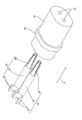
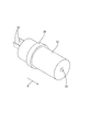
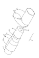
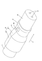
- FIG. 1 is a perspective view showing a female connector structure according to the first embodiment.
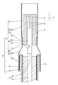
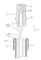
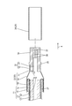
- Sectional drawing which shows a female connector structure
- Sectional drawing which shows the state which fitted the sleeve to the shield electric wire in the manufacturing process of a female connector structure.
- Sectional drawing which shows the state where the sheath of the shielded wire has been peeled off
- Sectional drawing which shows the state which folded the braided wire on the sleeve.
- Perspective view showing a state in which a female terminal is inserted into a dielectric
- Sectional drawing which shows the process of crimping a wire barrel to a core wire.
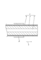
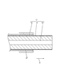
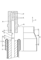
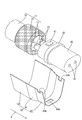
- Sectional drawing which shows the process of crimping a back outer conductor to a braided wire and a dielectric material. Sectional drawing which shows the process of crimping a front outer conductor to a rear outer conductor
- a perspective view showing a process of inserting a female terminal into a dielectric in a female connector structure concerning Embodiment 2 Perspective view showing a state in which a female terminal is inserted into a dielectric
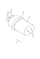
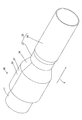
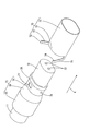
- FIG. 3 is a perspective view showing a female connector structure according to the second embodiment.
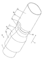
- FIG. 3 is a perspective view showing a female connector structure according to a third embodiment.
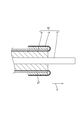
- a perspective view showing a process of crimping a rear outer conductor crimping piece to the rear outer conductor A perspective view showing a process of crimping a rear outer conductor crimping piece of a front outer conductor to a rear outer conductor in the female connector structure according to the fourth embodiment. Sectional drawing which shows the state in which the rear outer conductor crimping piece of the front outer conductor was crimped to the rear outer conductor.
- the female connector structure 10 has a female connector 12 connected to the end of a shielded electric wire 11.
- the female connector 12 includes a female terminal 18 (an example of an inner conductor), a dielectric 19, a rear outer conductor 33, and a front outer conductor 34.
- the direction in which the shielded electric wire 11 extends is the front.
- only some of the members may be denoted by the reference numerals, and other members may not be denoted by the reference numerals.
- Shielded wire 11 As shown in FIG. 2, in the shielded electric wire 11, a plurality (two in the present embodiment) of covered electric wires 13 are surrounded by a braided wire 14 (an example of a shield part) made of a fine metal wire, and the braided wire 14 is surrounded. Is surrounded by a sheath 15 made of an insulating material.
- Each covered electric wire 13 includes a core wire 16 and an insulating coating 17 surrounding the outer circumference of the core wire 16.
- any metal such as copper, copper alloy, aluminum, aluminum alloy, or the like can be selected as necessary.
- the core wire 16 may be made of one metal element wire, or may be made of a stranded wire in which a plurality of metal element wires are twisted together.
- the insulating coating 17 and the sheath 15 are made of insulating synthetic resin.
- the end of the shielded electric wire 11 is subjected to a terminal treatment such as peeling, and the respective ends of the core wire 16, the insulation coating 17, and the braided wire 14 are exposed.
- the female connector 12 includes a female terminal 18 (an example of an inner conductor), an insulating dielectric 19 that surrounds the outer periphery of the female terminal 18, and an outer conductor 20 that surrounds the outer periphery of the dielectric 19.
- the outer conductor 20 has a rear outer conductor 33 and a front outer conductor 34 electrically connected to the front end portion of the rear outer conductor 33.
- the female terminal 18 is formed by pressing a metal plate material into a predetermined shape.
- the metal forming the female terminal 18 any metal such as copper, copper alloy, aluminum, and aluminum alloy can be selected as necessary.
- the female terminal 18 is connected to the end of each covered electric wire 13.
- the female terminal 18 is connected to the wire barrel 22 (an example of a core wire connecting portion) that is crimped so as to be wound around the outer periphery of the core wire 16, and the connecting tubular portion 23 that is connected to the front of the wire barrel 22 and into which a mating terminal (not shown) is inserted. (An example of a connecting portion).
- a plurality of elastic contact pieces 24 extending in the front-rear direction are provided in the connecting tubular portion 23 by forming a plurality of slits extending rearward from the front end portion of the connecting tubular portion 23.
- the plurality of elastic contact pieces 24 are reduced in diameter toward the front, and are elastically deformable in the radial direction of the connecting tubular portion 23.
- the braided wire 14 is formed by braiding a plurality of thin metal wires in a tubular shape. A portion of the braided wire 14 exposed from the end of the sheath 15 is folded back to the end of the sheath 15 and overlapped on the outer side of a sleeve 27 described later.
- annular sleeve 27 is fitted on the outside of the end of the sheath 15, and the braided wire 14 is overlaid on the outside of the sleeve 27 as described above.
- the sleeve 27 according to the present embodiment is formed in a substantially annular shape by crimping an elongated metal plate material so as to wind around the outer periphery of the sheath 15.
- Dielectric 19 As shown in FIG. 2, the periphery of the connecting tubular portion 23 of the female terminal 18 is surrounded by the dielectric material 19.
- the dielectric 19 is formed by injection molding an insulating synthetic resin.
- a wire barrel 22 projects rearward from the rear end of the dielectric 19.
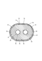
- the dielectric 19 extends in the front-rear direction as a whole and has a cross-sectional shape that is an elongated oval shape in the left-right direction.
- the dielectric 19 is opened in the front-rear direction, and a plurality of (two in the present embodiment) cavities 32 in which the connection tubular portions 23 of the female terminals 18 are respectively housed are formed side by side in the left-right direction. ..
- a mating terminal is inserted through the front opening of the cavity 32.
- the wire barrel 22 is led out from the opening on the rear side of the cavity 32.
- a flange 28 protruding outward in the radial direction of the dielectric 19 is formed in a portion of the dielectric 19 approximately one-third from the rear end in the front-rear direction.
- Rear outer conductor 33 As shown in FIGS. 2 and 9, the rear outer conductor 33 is formed by pressing a metal plate material into a predetermined shape. As the metal forming the rear outer conductor 33, any metal such as copper, copper alloy, aluminum, and aluminum alloy can be selected as necessary.
- the rear outer conductor 33 is connected to the shield connecting portion 35 that is crimped from the outside to the braided wire 14 folded back on the sleeve 27, and is connected to the front of the shield connecting portion 35, and the outer circumference of the covered electric wire 13 exposed from the braided wire 14
- the rear outer conductor 33 is crimped to the outer periphery of the braided wire 14 and is crimped from the outside to a position near the rear end of the dielectric 19 in a form in which the left and right edges are attached to each other.
- the dielectric pressure-bonding portion 37 is pressure-bonded to a portion of the dielectric 19 that is behind the flange 28. The front end of the dielectric pressure-bonding portion 37 comes into contact with the flange 28 from the rear, whereby the rear outer conductor 33 and the dielectric 19 can be positioned in the front-rear direction.
- the outer diameter dimension of the shield connecting portion 35 is larger than that of the dielectric crimping portion 37. Is also set large.
- the rear tubular portion 36 which is located between the shield connecting portion 35 and the dielectric pressure-bonding portion 37, is formed in a shape in which the diameter is reduced toward the front.
- the front outer conductor 34 is formed by pressing a metal plate material into a predetermined shape.
- any metal such as copper, copper alloy, aluminum, and aluminum alloy can be selected as necessary.
- the front outer conductor 34 is connected to a front cylindrical portion 38 (an example of a cylindrical portion) that surrounds the outer periphery of the dielectric 19 and a dielectric that is connected to the rear of the front cylindrical portion 38 and pressure-bonded to a portion near the rear end of the dielectric 19. It has a rear outer conductor locking portion 39 that is crimped on the body crimping portion 37.
- the front end portion of the front tubular portion 38 is formed to extend forward of the front end portion of the dielectric body 19.
- the rear outer conductor locking portion 39 is crimped onto the dielectric crimp portion 37 of the rear outer conductor 33 behind the flange 28 of the dielectric material 19.
- the diameter of the rear outer conductor locking portion 39 is smaller than that of the front cylindrical portion 38.
- the sleeve 27 is fitted on the outer periphery of the sheath 15 at a position retracted from the end portion of the shielded electric wire 11 by a predetermined length dimension.
- the braided wire 14 is exposed from the sheath 15 by peeling off a portion of the sheath 15 in front of the front end portion of the sleeve 27.
- the braided wire 14 is cut into a predetermined length, and the covered electric wire 13 is exposed from the braided wire 14.
- the sleeve 27 serves as a mark for the position where the sheath 15 is peeled off.
- the braided wire 14 is folded back and overlapped on the sleeve 27.
- the insulation coating 17 is peeled off with a predetermined length to expose the core wire 16 from the insulation coating 17.
- the female terminal 18 is inserted into the cavity 32 of the dielectric 19 from the rear.
- the wire barrel 22 of the female terminal 18 projects rearward from the rear end of the dielectric 19.
- the female barrel 18 is connected to the end of the coated electric wire 13 by crimping the wire barrel 22 to the outer periphery of the core wire 16 exposed from the front end of the insulating coating 17 (see FIG. 9 ).
- the shield connecting portion 35 of the rear outer conductor 33 is crimped from the outside to the braided wire 14 folded back on the sleeve 27. Further, the dielectric pressure-bonding portion 37 of the rear outer conductor 33 is pressure-bonded to the portion of the dielectric 19 rearward of the flange 28 from the outside.
- the step of crimping the shield connecting portion 35 to the braided wire 14 and the step of crimping the dielectric crimping portion 37 to the dielectric 19 may be performed in the same step. Further, the step of crimping the shield connecting portion 35 to the braided wire 14 and the step of crimping the dielectric crimping portion 37 to the dielectric 19 may be performed separately.
- the shield crimp portion 35 may be crimped to the braided wire 14 first, and then the dielectric crimp portion 37 may be crimped to the dielectric material 19. Alternatively, the dielectric crimp portion 37 may be crimped to the dielectric material 19 and then the shield connection may be performed.
- the portion 35 may be crimped to the braided wire 14.
- the front outer conductor 34 is formed into a tubular shape. As shown in FIG. 10, the cylindrical outer front conductor 34 is assembled to the dielectric 19 from the front of the dielectric 19. The rear outer conductor locking portion 39 of the front outer conductor 34 is pressure-bonded to the dielectric material 19, and then the dielectric outer-layer 33 of the outer conductor 33 is pressure-bonded from the outside. By the above, the female connector structure 10 is completed (see FIGS. 1 and 2).
- the female connector structure 10 includes the shielded electric wire 11 in which the outer circumference of the core wire 16 extending in the front-rear direction is surrounded by the insulating coating 17 and the outer circumference of the covered wire 13 is surrounded by the braided wire 14, and the core wire.
- a female terminal 18 having a wire barrel 22 connected to 16 and a connecting tube portion 23 connected to the mating terminal connected to the wire barrel 22 and at least surrounding the outer periphery of the connecting tube portion 23 of the female terminal 18.
- a rear outer conductor 33 having an insulating dielectric 19 and a shield connecting portion 35 electrically connected to the braided wire 14, and a dielectric crimping portion 37 crimping from at least a part of the dielectric 19 from the outside.
- a front outer conductor 34 that has a front cylindrical portion 38 that surrounds the outer periphery of the dielectric 19 and a rear outer conductor locking portion 39 that locks at least a part of the dielectric pressure bonding portion 37 from the outside.
- the outer circumference of the coated wire 13 in which the outer circumference of the core wire 16 extending in the front-rear direction is surrounded by the insulating coating 17 is surrounded by the braided wire 14.
- a step of peeling off the insulation coating 17 of the shielded electric wire 11 to expose the core wire 16, a step of disposing the female terminal 18 on the insulating dielectric 19 with the wire barrel 22 exposed, and an insulation coating At least the step of connecting the wire barrel 22 of the female terminal 18 to the core wire 16 exposed from 17, the step of connecting the rear outer conductor 33 to the braided wire 14, and the dielectric pressure-bonding portion 37 of the rear outer conductor 33 are at least the dielectric.
- the rear outer conductor 33 and the front outer conductor 34 are crimped to at least a part of the dielectric 19 by the dielectric crimping portion 37 of the rear outer conductor 33, and at least the dielectric crimping portion 37.
- the rear outer conductor locking portion 39 is connected to a part of the above by being connected.
- the rear outer conductor 33 and the front outer conductor 34 can be connected without welding.
- the rear outer conductor 33 and the front outer conductor 34 can be connected to each other without heating, so that the dielectric 19 can be prevented from being defective due to heat.
- the dielectric 51 has a substantially cylindrical shape extending in the front-rear direction.
- the dielectric 51 is formed with one cavity 32 that is open in the front and rear.
- One female terminal 18 is accommodated in the cavity 32.
- the rear outer conductor 52 includes a shield connecting portion 53 having a substantially cylindrical shape, and a dielectric crimping portion (not shown) formed coaxially with the shield connecting portion 53 and having a substantially cylindrical shape.
- the front outer conductor 55 has a front cylindrical portion 56 having a substantially cylindrical shape, and a rear outer conductor locking portion 57 formed coaxially with the front cylindrical portion 56 and having a substantially cylindrical shape.
- the dielectric body 51 according to the present embodiment can be effectively applied to the female connector structure 50 including the shielded electric wire 11 in which one covered electric wire 13 is arranged in the sheath 15.
- the rear outer conductor locking portion 60 has a pair of rear end portions that are crimped so as to be wound around the outer periphery of the dielectric crimp portion 37 from the left side and the right side, respectively.
- a rear outer conductor crimping piece 61 is provided. The edges of the pair of rear outer conductor crimping pieces 61 are in a state of abutting each other.
- the rear outer conductor 33 and the front outer conductor 62 can be reliably connected.
- a pair of rear outer conductor crimping pieces 72 are provided at the rear end portion of the rear outer conductor locking portion 71 of the front outer conductor 70 according to the present embodiment.
- an expansion suppressing portion 74 folded back inward in the radial direction of the front tubular portion 73 is provided.
- the expansion suppressing portion 74 is formed to project toward the dielectric crimping portion 76. ing.
- a recess 77 is formed in the dielectric pressure-bonding portion 76 of the rear outer conductor 75 at a position corresponding to the expansion suppressing portion 74.
- the recess 77 has a rectangular shape when viewed from above.
- connection protrusion 78 is configured to contact the inner surface of the rear outer conductor crimping piece 72 in a state where the rear outer conductor crimping piece 72 is crimped to the outer periphery of the dielectric crimping portion 76.
- the rear outer conductor 75 and the front outer conductor 70 can be electrically connected.
- the electrical connection reliability between the rear outer conductor 75 and the front outer conductor 70 can be improved.
- a fifth embodiment of the technique disclosed in this specification will be described with reference to FIGS. 18 to 19.
- a locking projection 81 that projects upward is provided at a position behind the flange 28.
- a locking projection (not shown) protruding downward is provided at a position behind the flange 28.
- the locking protrusion 81 provided on the upper side of the dielectric 80 and the locking protrusion 81 provided on the lower side are formed at symmetrical positions in the vertical direction.
- the upper locking protrusion 81 and the lower locking protrusion have a rectangular shape when viewed in the vertical direction.
- a locking concave portion 84A is formed at a position corresponding to the locking convex portion 81 when the dielectric pressure bonding portion 83 is pressure-bonded to the dielectric 80.
- a locking recess 84A is formed in the upper portion of the dielectric pressure-bonding portion 83 in a state where the left and right edges of the rear outer conductor 82 are butted against each other.
- the locking recess 84A has a rectangular shape when viewed from above.
- the inner shape of the locking concave portion 84A is the same as or slightly larger than the outer shape of the locking convex portion 81.
- the locking projection 81 is fitted into the locking recess 84A.
- the protruding end surface of the locking convex portion 81 is formed flush with the outer surface of the dielectric pressure-bonded portion 83.
- the dielectric pressure-bonding portion 83 of the rear outer conductor 82 is locked at a position corresponding to the locking projection formed on the lower side of the dielectric 80 while the dielectric pressure-bonding portion 83 is pressure-bonded to the dielectric 80.
- a recess 84B is formed.
- the locking recess 84B has a rectangular shape when viewed from below.
- the inner shape of the locking concave portion 84B is the same as or slightly larger than the outer shape of the locking convex portion formed on the lower side of the dielectric 80.
- the protruding end surface of the locking protrusion formed on the lower side of the dielectric 80 is formed flush with the outer surface of the dielectric pressure-bonded portion 83.
- the locking projection 81 formed on the upper side of the dielectric 80 and the locking recess 84A are fitted in the concave and convex, and the locking projection formed on the lower side of the dielectric 80 is engaged.
- the stopper recesses 84B By fitting the stopper recesses 84B into the recesses and protrusions, the relative positional accuracy between the rear outer conductor 82 and the dielectric 80 can be improved.
- the shielded electric wire may have three or more covered electric wires.
- the shield layer is not limited to the braided wire 14, and any material such as a metal foil or a resin tape to which a metal foil is attached can be appropriately selected.
- the sheath may be omitted.
- the braided wire 14 exposed by peeling off the sheath may be configured not to be folded back to the end of the sheath.
- the crimping member formed separately from the rear outer conductor 33 is crimped to the shield connecting portion from outside the shield connecting portion while the shield connecting portion 35 is fitted on the outer periphery of the braided wire 14.
- the braided wire 14 and the shield connecting portion 35 may be electrically connected.
- the connector structure may be a male terminal structure including male terminals.
- the rear outer conductor crimping piece 72 may be provided on its inner surface with a connecting projection that projects toward the dielectric crimping portion 76.
- the dielectric 80 may be provided with the locking concave portion, and the dielectric pressure-bonding portion may be provided with the locking convex portion. Further, the number of the locking concave portions and the number of the locking convex portions may each be one, or may be three or more.
Landscapes
- Engineering & Computer Science (AREA)
- Manufacturing & Machinery (AREA)
- Coupling Device And Connection With Printed Circuit (AREA)
- Manufacturing Of Electrical Connectors (AREA)
- Details Of Connecting Devices For Male And Female Coupling (AREA)
Abstract
雌コネクタ構造体10は、芯線16の外周を絶縁被覆17で包囲してなる被覆電線13の外周が編組線14で包囲されたシールド電線11と、芯線16に接続されるワイヤーバレル22を有すると共にワイヤーバレル22に連なって相手側端子と接続する接続筒部23を有する雌端子18と、少なくとも、雌端子18のうち接続筒部23の外周を包囲する絶縁性の誘電体19と、編組線14に電気的に接続されるシールド接続部35を有すると共に、少なくとも誘電体19の一部に外方から圧着する誘電体圧着部37を有する後外導体33と、誘電体19の外周を包囲する前筒部38を有すると共に、少なくとも誘電体圧着部37の一部に外方から係止する後外導体係止部39を有する前外導体34と、を備える。
Description
本明細書に開示された技術は、シールド電線にコネクタが接続されてなるコネクタ構造体、及びコネクタ構造体の製造方法に関する。
同軸ケーブルの端末にコネクタが接続されてなるコネクタ構造体として、国際公開第2017/144070号に記載のものが知られている。このコネクタ構造体は、内導体と、内導体を包囲する誘電体と、誘電体の外周を覆う接触部材と、同軸ケーブルのシールド部に接続される接続部材と、を備える。接触部材の後端部には接続部材の前端部が外嵌された状態で、溶接されるようになっている。これにより、接触部材と接続部材とが電気的に接続される。
しかしながら、上記の構成によれば、誘電体が接触部材の内部に収容された状態で、接触部材と接続部材とが溶接されるようになっている。このため、接触部材と接続部材との溶接時の熱によって、誘電体が変形する等の不具合が生じる虞がある。
本明細書に開示された技術は上記のような事情に基づいて完成されたものであって、熱によって誘電体に不具合が生じることが抑制されたコネクタ構造体を提供することを目的とする。
本明細書に開示された技術は、コネクタ構造体であって、前後方向に延びる芯線の外周を絶縁被覆で包囲してなる被覆電線の外周がシールド部で包囲されたシールド電線と、前記芯線に接続される芯線接続部を有すると共に前記芯線接続部に連なって相手側端子と接続する接続部を有する内導体と、少なくとも、前記内導体のうち前記接続部の外周を包囲する絶縁性の誘電体と、前記シールド部に電気的に接続されるシールド接続部を有すると共に、少なくとも前記誘電体の一部に外方から圧着する誘電体圧着部を有する後外導体と、前記誘電体の外周を包囲する筒部を有すると共に、少なくとも前記誘電体圧着部の一部に外方から係止する後外導体係止部を有する前外導体と、を備える。
また、本明細書に開示された技術は、コネクタ構造体の製造方法であって、前後方向に延びる芯線の外周を絶縁被覆で包囲してなる被覆電線の外周がシールド部で包囲されたシールド電線の前記絶縁被覆の前端部を皮剥ぎして前記芯線を露出させる工程と、絶縁性の誘電体に、芯線接続部を露出させた状態で内導体を配設する工程と、前記絶縁被覆から露出した前記芯線に、前記内導体の芯線接続部を接続する工程と、前記シールド部に後外導体を接続する工程と、前記後外導体の誘電体圧着部を、少なくとも前記誘電体の一部に外方から圧着する工程と、前記誘電体を前外導体の内部に収容する工程と、前記前外導体に設けられた後外導体係止部を、少なくとも前記誘電体圧着部の一部に係止する工程と、を備える。
上記の技術によれば、後外導体と、前外導体とは、少なくとも誘電体の一部に、後導体の誘電体圧着部が圧着すると共に、少なくとも誘電体圧着部の一部に後外導体圧着部が係止することにより、接続されている。これにより、加熱することなく、後外導体と前外導体とを接続することができるので、熱によって誘電体に不具合が生じることを抑制することができる。
本明細書に開示された技術の実施態様としては以下の態様が好ましい。
前記後外導体係止部は、前記誘電体圧着部の外周に巻き付くように圧着する後外導体圧着片を有する。
上記の構成によれば、後外導体と前外導体とを確実に接続することができる。
前記後外導体係止部には、前記後外導体係止部が前記誘電体圧着部の外周に圧着した状態で、前記誘電体圧着部に向かって突出する拡開抑制部が設けられており、前記拡開抑制部は、前記誘電体圧着部に設けられた凹部内に嵌入して、前記誘電体の周方向について前記凹部の内壁に係止している。
上記の構成によれば、誘電体の周方向について、拡開抑制部が凹部の内壁と係止しているので、後外導体係止部が拡開変形することを抑制することができる。
前記後外導体係止部、及び前記誘電体圧着部の一方には、他方に向かって突出する接続突部が設けられている。
上記の構成によれば、後外導体係止部、及び誘電体圧着部の一方に設けられた接続突部が、他方に当接することにより、後外導体と、前外導体とを確実に電気的に接続することができる。これにより、後外導体と前外導体との電気的な接続信頼性を向上させることができる。
前記誘電体に前記誘電体圧着部が圧着した状態で、前記誘電体及び前記誘電体圧着部の一方に設けられた係止凸部と、他方に設けられた係止凹部とが、凹凸嵌合している。
上記の構成によれば、後外導体と、誘電体とを、前後方向について位置決めすることができる。これにより、コネクタ構造体を構成する部品の位置精度を向上させることができる。
本明細書に開示された技術によれば、熱によって誘電体に不具合が生じることを抑制することができる。
<実施形態1>
本明細書に開示された技術の実施形態1を図1から図10を参照しつつ説明する。本実施形態に係る雌コネクタ構造体10は、シールド電線11の端末に雌コネクタ12が接続されてなる。雌コネクタ12は、雌端子18(内導体の一例)と、誘電体19と、後外導体33と、前外導体34と、を備える。以下の説明では、シールド電線11の延びる方向(矢線Aで示す方向)を前方とする。また、複数の同一部材については、一部の部材にのみ符号を付し、他の部材については符号を省略する場合がある。
本明細書に開示された技術の実施形態1を図1から図10を参照しつつ説明する。本実施形態に係る雌コネクタ構造体10は、シールド電線11の端末に雌コネクタ12が接続されてなる。雌コネクタ12は、雌端子18(内導体の一例)と、誘電体19と、後外導体33と、前外導体34と、を備える。以下の説明では、シールド電線11の延びる方向(矢線Aで示す方向)を前方とする。また、複数の同一部材については、一部の部材にのみ符号を付し、他の部材については符号を省略する場合がある。
シールド電線11
図2に示すように、シールド電線11は、複数(本実施形態では2本)の被覆電線13の外周を、金属細線からなる編組線14(シールド部の一例)で包囲すると共に、編組線14の外周を絶縁材料からなるシース15で包囲してなる。各被覆電線13は、芯線16と、芯線16の外周を包囲する絶縁被覆17と、を備える。芯線16を構成する金属は、銅、銅合金、アルミニウム、アルミニウム合金等、必要に応じて任意の金属を選択することができる。芯線16は、1本の金属素線からなるものであってもよく、また、複数本の金属素線が撚り合わされた撚り線からなるものであってもよい。絶縁被覆17、及びシース15は、絶縁性の合成樹脂からなる。
図2に示すように、シールド電線11は、複数(本実施形態では2本)の被覆電線13の外周を、金属細線からなる編組線14(シールド部の一例)で包囲すると共に、編組線14の外周を絶縁材料からなるシース15で包囲してなる。各被覆電線13は、芯線16と、芯線16の外周を包囲する絶縁被覆17と、を備える。芯線16を構成する金属は、銅、銅合金、アルミニウム、アルミニウム合金等、必要に応じて任意の金属を選択することができる。芯線16は、1本の金属素線からなるものであってもよく、また、複数本の金属素線が撚り合わされた撚り線からなるものであってもよい。絶縁被覆17、及びシース15は、絶縁性の合成樹脂からなる。
シールド電線11の端末においては、皮剥ぎ等の端末処理が施され、芯線16、絶縁被覆17、及び編組線14のそれぞれの端末が露出している。
雌コネクタ12
雌コネクタ12は、雌端子18(内導体の一例)と、雌端子18の外周を包囲する絶縁性の誘電体19と、誘電体19の外周を包囲する外導体20と、を備える。外導体20は、後外導体33と、後外導体33の前端部に電気的に接続された前外導体34とを、有する。
雌コネクタ12は、雌端子18(内導体の一例)と、雌端子18の外周を包囲する絶縁性の誘電体19と、誘電体19の外周を包囲する外導体20と、を備える。外導体20は、後外導体33と、後外導体33の前端部に電気的に接続された前外導体34とを、有する。
雌端子18
図6に示すように、雌端子18は、金属板材を所定の形状にプレス加工してなる。雌端子18を構成する金属としては、銅、銅合金、アルミニウム、アルミニウム合金等、必要に応じて任意の金属を選択することができる。雌端子18は、各被覆電線13の端末に接続されている。雌端子18は、芯線16の外周に巻き付くように圧着するワイヤーバレル22(芯線接続部の一例)と、ワイヤーバレル22の前方に連なって、図示しない相手側端子が挿入される接続筒部23(接続部の一例)と、を有する。
図6に示すように、雌端子18は、金属板材を所定の形状にプレス加工してなる。雌端子18を構成する金属としては、銅、銅合金、アルミニウム、アルミニウム合金等、必要に応じて任意の金属を選択することができる。雌端子18は、各被覆電線13の端末に接続されている。雌端子18は、芯線16の外周に巻き付くように圧着するワイヤーバレル22(芯線接続部の一例)と、ワイヤーバレル22の前方に連なって、図示しない相手側端子が挿入される接続筒部23(接続部の一例)と、を有する。
接続筒部23には、接続筒部23の前端部から後方に向かって延びる複数のスリットが形成されることにより、前後方向に延びる複数の弾性接触片24が設けられている。複数の弾性接触片24は、前方に向かうに従って縮径しており、接続筒部23の径方向について弾性変形可能に形成されている。相手側端子が接続筒部23内に挿入されることにより、相手側端子と弾性接触片24とが弾性的に接触し、これにより、相手側端子と雌端子18とが電気的に接続されるようになっている。
編組線14
編組線14は、複数の金属細線を筒状に編んでなる。編組線14のうちシース15の端末から露出した部分は、シース15の端末側に折り返されて、後述するスリーブ27の外側に重ねられている。
編組線14は、複数の金属細線を筒状に編んでなる。編組線14のうちシース15の端末から露出した部分は、シース15の端末側に折り返されて、後述するスリーブ27の外側に重ねられている。
スリーブ27
シース15の端末の外側には、環状をなすスリーブ27が外嵌されている、スリーブ27の外側には、上記したように編組線14が重ねられている。本実施形態に係るスリーブ27は、細長く延びた金属板材を、シース15の外周に巻き付くように圧着させることにより、略環状に形成してなる。
シース15の端末の外側には、環状をなすスリーブ27が外嵌されている、スリーブ27の外側には、上記したように編組線14が重ねられている。本実施形態に係るスリーブ27は、細長く延びた金属板材を、シース15の外周に巻き付くように圧着させることにより、略環状に形成してなる。
誘電体19
図2に示すように、雌端子18のうち接続筒部23の周囲は、誘電体19によって包囲されるようになっている。誘電体19は絶縁性の合成樹脂を射出成型してなる。誘電体19の後端部からは、ワイヤーバレル22が後方に突出している。図6及び図7に示すように、誘電体19は、全体として前後方向に延びると共に、断面形状が、左右方向に細長い長円形状をなしている。
図2に示すように、雌端子18のうち接続筒部23の周囲は、誘電体19によって包囲されるようになっている。誘電体19は絶縁性の合成樹脂を射出成型してなる。誘電体19の後端部からは、ワイヤーバレル22が後方に突出している。図6及び図7に示すように、誘電体19は、全体として前後方向に延びると共に、断面形状が、左右方向に細長い長円形状をなしている。
誘電体19は、前後方向に開口すると共に、内部に雌端子18の接続筒部23がそれぞれ収容される複数(本実施形態では2つ)のキャビティ32が、左右方向に並んで形成されている。キャビティ32の前側の開口からは、相手側端子が挿入されるようになっている。キャビティ32の後側の開口からは、上記したように、ワイヤーバレル22が後方に導出されている。
誘電体19のうち、前後方向について後端部から略三分の一の部分には、誘電体19の径方向について外方に突出したフランジ28が形成されている。
後外導体33
図2及び図9に示すように、後外導体33は、金属板材を所定の形状にプレス加工してなる。後外導体33を構成する金属は銅、銅合金、アルミニウム、アルミニウム合金等、任意の金属を必要に応じて選択できる。後外導体33は、スリーブ27の上に折り返された編組線14に外方から圧着するシールド接続部35と、シールド接続部35の前方に連なって、編組線14から露出した被覆電線13の外周を包囲する後筒部36と、後筒部36の前方に連なって、誘電体19の後端部寄りの位置に外方から圧着する誘電体圧着部37と、を有する。
図2及び図9に示すように、後外導体33は、金属板材を所定の形状にプレス加工してなる。後外導体33を構成する金属は銅、銅合金、アルミニウム、アルミニウム合金等、任意の金属を必要に応じて選択できる。後外導体33は、スリーブ27の上に折り返された編組線14に外方から圧着するシールド接続部35と、シールド接続部35の前方に連なって、編組線14から露出した被覆電線13の外周を包囲する後筒部36と、後筒部36の前方に連なって、誘電体19の後端部寄りの位置に外方から圧着する誘電体圧着部37と、を有する。
後外導体33は、左右の両側縁が付き合わされた形態で、編組線14の外周に圧着すると共に、誘電体19の後端部寄りの位置に外方から圧着している。誘電体圧着部37は、誘電体19のうちフランジ28よりも後方の部分に圧着している。誘電体圧着部37の前端部が、フランジ28に後方から当接することにより、後外導体33と、誘電体19との、前後方向の位置決めを行うことができる。
後外導体33が編組線14の外周に圧着すると共に誘電体19の後端部寄りの位置に圧着した状態で、シールド接続部35の外径寸法は、誘電体圧着部37の外径寸法よりも大きく設定されている。シールド接続部35と誘電体圧着部37との間に位置する後筒部36は、前方に向かうに従って縮径した形状に形成されている。
前外導体34
図2に示すように、前外導体34は、金属板材を所定の形状にプレス加工してなる。前外導体34を構成する金属は銅、銅合金、アルミニウム、アルミニウム合金等、任意の金属を必要に応じて選択できる。前外導体34は、誘電体19の外周を包囲する前筒部38(筒部の一例)と、前筒部38の後方に連なって、誘電体19の後端部寄りの部分に圧着した誘電体圧着部37の上に圧着する後外導体係止部39を有する。前筒部38の前端部は、誘電体19の前端部よりも前方に延びて形成されている。後外導体係止部39は、誘電体19のフランジ28よりも後方において、後外導体33の誘電体圧着部37の上に圧着している。後外導体係止部39は、前筒部38よりも縮径されている。
図2に示すように、前外導体34は、金属板材を所定の形状にプレス加工してなる。前外導体34を構成する金属は銅、銅合金、アルミニウム、アルミニウム合金等、任意の金属を必要に応じて選択できる。前外導体34は、誘電体19の外周を包囲する前筒部38(筒部の一例)と、前筒部38の後方に連なって、誘電体19の後端部寄りの部分に圧着した誘電体圧着部37の上に圧着する後外導体係止部39を有する。前筒部38の前端部は、誘電体19の前端部よりも前方に延びて形成されている。後外導体係止部39は、誘電体19のフランジ28よりも後方において、後外導体33の誘電体圧着部37の上に圧着している。後外導体係止部39は、前筒部38よりも縮径されている。
雌コネクタ構造体10の製造工程
続いて、本実施形態に係る雌コネクタ構造体10の製造工程の一例について説明する。なお、雌コネクタ構造体10の製造工程は以下の記載に限定されない。
続いて、本実施形態に係る雌コネクタ構造体10の製造工程の一例について説明する。なお、雌コネクタ構造体10の製造工程は以下の記載に限定されない。
図3に示すように、シールド電線11の端末部分から所定の長さ寸法だけ後退した位置に、シース15の外周にスリーブ27を外嵌させる。図4に示すように、シース15のうち、スリーブ27の前端部よりも前方の部分を皮剥ぎすることにより、編組線14をシース15から露出させる。編組線14を所定の長さに切断し、編組線14から被覆電線13を露出させる。スリーブ27は、シース15を皮剥ぎする位置の目印となっている。図5に示すように、編組線14を後方に折り返して、スリーブ27の上に重ねる。被覆電線13の端末において、所定の長さで絶縁被覆17を皮剥ぎすることにより、芯線16を絶縁被覆17から露出させる。
図6に示すように、誘電体19のキャビティ32内に、雌端子18を後方から挿入する。図8に示すように、誘電体19の後端部からは、雌端子18のワイヤーバレル22が後方に突出している。絶縁被覆17の前端部から露出した芯線16の外周にワイヤーバレル22を圧着させることにより、被覆電線13の端末に雌端子18を接続する(図9参照)。
図9に示すように、後外導体33のシールド接続部35を、スリーブ27の上に折り返された編組線14に、外方から圧着する。また、後外導体33の誘電体圧着部37を誘電体19のうちフランジ28よりも後方の部分に、外方から圧着する。
シールド接続部35を編組線14に圧着する工程と、誘電体圧着部37を誘電体19に圧着する工程は、同一の工程内で実行してもよい。また、シールド接続部35を編組線14に圧着する工程と、誘電体圧着部37を誘電体19に圧着する工程は、別々に実行してもよい。例えば、先にシールド接続部35を編組線14に圧着した後に誘電体圧着部37を誘電体19に圧着してもよいし、先に誘電体圧着部37を誘電体19に圧着した後にシールド接続部35を編組線14に圧着してもよい。
前外導体34を筒状に形成する。図10に示すように、筒状に形成された前外導体34を、誘電体19の前方から、誘電体19に組み付ける。前外導体34の後外導体係止部39を、誘電体19に圧着した後外導体33の誘電体圧着部37に、外方から圧着させる。以上により、雌コネクタ構造体10が完成する(図1及び図2参照)。
本実施形態の作用効果
続いて、本実施形態の作用効果について説明する。本実施形態によれば、雌コネクタ構造体10は、前後方向に延びる芯線16の外周を絶縁被覆17で包囲してなる被覆電線13の外周が編組線14で包囲されたシールド電線11と、芯線16に接続されるワイヤーバレル22を有すると共にワイヤーバレル22に連なって相手側端子と接続する接続筒部23を有する雌端子18と、少なくとも、雌端子18のうち接続筒部23の外周を包囲する絶縁性の誘電体19と、編組線14に電気的に接続されるシールド接続部35を有すると共に、少なくとも誘電体19の一部に外方から圧着する誘電体圧着部37を有する後外導体33と、誘電体19の外周を包囲する前筒部38を有すると共に、少なくとも誘電体圧着部37の一部に外方から係止する後外導体係止部39を有する前外導体34と、を備える。
続いて、本実施形態の作用効果について説明する。本実施形態によれば、雌コネクタ構造体10は、前後方向に延びる芯線16の外周を絶縁被覆17で包囲してなる被覆電線13の外周が編組線14で包囲されたシールド電線11と、芯線16に接続されるワイヤーバレル22を有すると共にワイヤーバレル22に連なって相手側端子と接続する接続筒部23を有する雌端子18と、少なくとも、雌端子18のうち接続筒部23の外周を包囲する絶縁性の誘電体19と、編組線14に電気的に接続されるシールド接続部35を有すると共に、少なくとも誘電体19の一部に外方から圧着する誘電体圧着部37を有する後外導体33と、誘電体19の外周を包囲する前筒部38を有すると共に、少なくとも誘電体圧着部37の一部に外方から係止する後外導体係止部39を有する前外導体34と、を備える。
また、本明細書に開示された、雌コネクタ構造体10の製造方法は、前後方向に延びる芯線16の外周を絶縁被覆17で包囲してなる被覆電線13の外周が編組線14で包囲されたシールド電線11の、絶縁被覆17を皮剥ぎして芯線16を露出させる工程と、絶縁性の誘電体19に、ワイヤーバレル22を露出させた状態で雌端子18を配設する工程と、絶縁被覆17から露出した芯線16に、雌端子18のワイヤーバレル22を接続する工程と、編組線14に後外導体33を接続する工程と、後外導体33の誘電体圧着部37を、少なくとも誘電体19の一部に外方から圧着する工程と、誘電体19を前外導体34の内部に収容する工程と、前外導体34に設けられた後外導体係止部39を、少なくとも誘電体圧着部37の一部に係止する工程と、を備える。
上記の構成によれば、後外導体33と、前外導体34とは、少なくとも誘電体19の一部に、後外導体33の誘電体圧着部37が圧着すると共に、少なくとも誘電体圧着部37の一部に後外導体係止部39が係止することにより、接続されている。これにより、後外導体33と前外導体34とを、溶接によらずに、接続することができる。この結果、後外導体33と前外導体34とを、加熱することなく、接続することができるので、熱によって誘電体19に不具合が生じることを抑制することができる。
<実施形態2>
次に、本明細書に開示された技術の実施形態2を図11から図13を参照しつつ説明する。本実施形態に係る雌コネクタ構造体50においては、誘電体51は、前後方向に延びる、略円筒形状をなしている。誘電体51には、前後に開口する、1つのキャビティ32が形成されている。キャビティ32内には、1つの雌端子18が収容されている。
次に、本明細書に開示された技術の実施形態2を図11から図13を参照しつつ説明する。本実施形態に係る雌コネクタ構造体50においては、誘電体51は、前後方向に延びる、略円筒形状をなしている。誘電体51には、前後に開口する、1つのキャビティ32が形成されている。キャビティ32内には、1つの雌端子18が収容されている。
後外導体52は、略円筒形状をなすシールド接続部53と、このシールド接続部53と同軸上に形成されると共に略円筒形状をなす誘電体圧着部(図示せず)と、を備える。
前外導体55は、略円筒形状をなす前筒部56と、この前筒部56と同軸状に形成されると共に略円筒形状をなす後外導体係止部57と、を有する。
本実施形態に係る誘電体51は、シース15内に1つの被覆電線13が配されたシールド電線11を備えた雌コネクタ構造体50に対して、有効に適用することができる。
上記以外の構成については、実施形態1と略同様なので、同一部材については同一符号を付し、重複する説明を省略する。
<実施形態3>
次に、本明細書に開示された技術の実施形態3に係る雌コネクタ構造体63について図14から図15を参照しつつ説明する。本実施形態に係る前外導体62おいては、後外導体係止部60の後端部には、誘電体圧着部37の外周に左方及び右方からそれぞれ巻き付くように圧着する一対の後外導体圧着片61が設けられている。一対の後外導体圧着片61の端縁同士は互いに突き合わされた状態になっている。
次に、本明細書に開示された技術の実施形態3に係る雌コネクタ構造体63について図14から図15を参照しつつ説明する。本実施形態に係る前外導体62おいては、後外導体係止部60の後端部には、誘電体圧着部37の外周に左方及び右方からそれぞれ巻き付くように圧着する一対の後外導体圧着片61が設けられている。一対の後外導体圧着片61の端縁同士は互いに突き合わされた状態になっている。
上記の構成によれば、後外導体33と前外導体62とを確実に接続することができる。
上記以外の構成については、実施形態1と略同様なので、同一部材については同一符号を付し、重複する説明を省略する。
<実施形態4>
次に、本明細書に開示された技術の実施形態4について図16から図17を参照しつつ説明する。本実施形態に係る前外導体70の後外導体係止部71後端部には、一対の後外導体圧着片72が設けられている。一対の後外導体圧着片72の各端部には、前筒部73の径方向の内側に折り返された拡開抑制部74が設けられている。後外導体圧着片72が後外導体75の誘電体圧着部76の外周に巻き付くように圧着した状態で、拡開抑制部74は、誘電体圧着部76に向かって突出するように形成されている。
次に、本明細書に開示された技術の実施形態4について図16から図17を参照しつつ説明する。本実施形態に係る前外導体70の後外導体係止部71後端部には、一対の後外導体圧着片72が設けられている。一対の後外導体圧着片72の各端部には、前筒部73の径方向の内側に折り返された拡開抑制部74が設けられている。後外導体圧着片72が後外導体75の誘電体圧着部76の外周に巻き付くように圧着した状態で、拡開抑制部74は、誘電体圧着部76に向かって突出するように形成されている。
後外導体75の誘電体圧着部76には、拡開抑制部74に対応する位置に、凹部77が形成されている。凹部77は、上方から見て四角形状をなしている。後外導体圧着片72が誘電体圧着部76の外周に圧着した状態で、拡開抑制部74は、凹部77内に上方から嵌入するようになっている。これにより、誘電体19の周方向について、拡開抑制部74が凹部77の内壁に係止するようになっている。これにより、後外導体圧着片72(後外導体係止部71)が拡開変形することが抑制されるようになっている。
また、誘電体圧着部76の外面には、外方に突出する複数(本実施形態では4つ)の接続突部78が、誘電体圧着部76の周方向に間隔を空けて並んで形成されている。後外導体圧着片72が誘電体圧着部76の外周に圧着した状態で、接続突部78は、後外導体圧着片72の内面に当接するようになっている。これにより、後外導体75と、前外導体70とを電気的に接続することができる。この結果、後外導体75と前外導体70との電気的な接続信頼性を向上させることができる。
上記以外の構成については、実施形態3と略同様なので、同一部材については同一符号を付し、重複する説明を省略する。
<実施形態5>
次に、本明細書に開示された技術の実施形態5について図18から図19を参照しつつ説明する。本実施形態に係る誘電体80の上面には、フランジ28の後方の位置に、上方に突出する係止凸部81が設けられている。また、誘電体80の下面には、フランジ28の後方の位置に、下方に突出する係止凸部(図示せず)が設けられている。誘電体80の上側に設けられた係止凸部81と、下側に設けられた係止凸部とは、上下方向について対称な位置に形成されている。上側の係止凸部81及び下側の係止凸部は、上下方向から見て長方形状をなしている。
次に、本明細書に開示された技術の実施形態5について図18から図19を参照しつつ説明する。本実施形態に係る誘電体80の上面には、フランジ28の後方の位置に、上方に突出する係止凸部81が設けられている。また、誘電体80の下面には、フランジ28の後方の位置に、下方に突出する係止凸部(図示せず)が設けられている。誘電体80の上側に設けられた係止凸部81と、下側に設けられた係止凸部とは、上下方向について対称な位置に形成されている。上側の係止凸部81及び下側の係止凸部は、上下方向から見て長方形状をなしている。
後外導体82の誘電体圧着部83には、誘電体圧着部83が誘電体80に圧着した状態で、係止凸部81に対応する位置に、係止凹部84Aが形成されている。後外導体82の左右両側縁が突き合わされた状態で、誘電体圧着部83の上部に、係止凹部84Aが形成されるようになっている。係止凹部84Aは、上方から見て長方形状をなしている。係止凹部84Aの内形状は、係止凸部81の外形状と同じか、やや大きく形成されている。誘電体圧着部83が誘電体80に圧着した状態で、係止凸部81が係止凹部84A内に嵌入するようになっている。誘電体圧着部83が誘電体80に圧着した状態で、係止凸部81の突出端面は、誘電体圧着部83の外面と面一に形成されている。
後外導体82の誘電体圧着部83には、誘電体圧着部83が誘電体80に圧着した状態で、誘電体80の下側に形成された係止凸部に対応する位置に、係止凹部84Bが形成されている。係止凹部84Bは、下方から見て長方形状をなしている。係止凹部84Bの内形状は、誘電体80の下側に形成された係止凸部の外形状と同じか、やや大きく形成されている。誘電体圧着部83が誘電体80に圧着した状態で、誘電体80の下側に形成された係止凸部が係止凹部84B内に嵌入するようになっている。誘電体圧着部83が誘電体80に圧着した状態で、誘電体80の下側に形成された係止凸部の突出端面は、誘電体圧着部83の外面と面一に形成されている。
上記以外の構成については、実施形態1と略同様なので、同一部材については同一符号を付し、重複する説明を省略する。
上記の構成によれば、誘電体80の上側に形成された係止凸部81と係止凹部84Aとが凹凸嵌合すると共に、誘電体80の下側に形成された係止凸部と係止凹部84Bとが凹凸嵌合することにより、後外導体82と誘電体80との相対的な位置精度を向上させることができる。
<他の実施形態>
本明細書に開示された技術は上記記述及び図面によって説明した実施形態に限定されるものではなく、例えば次のような実施形態も本明細書に開示された技術の技術的範囲に含まれる。
本明細書に開示された技術は上記記述及び図面によって説明した実施形態に限定されるものではなく、例えば次のような実施形態も本明細書に開示された技術の技術的範囲に含まれる。
(1)シールド電線は、3本以上の被覆電線を有する構成としてもよい。
(2)シールド層は編組線14に限られず、金属箔、又は、樹脂テープに金属箔が貼着されたもの等、任意の材料を適宜に選択することができる。
(3)シースは省略してもよい。
(4)シースを皮剥ぎして露出させた編組線14は、シースの端末に折り返さない構成としてもよい。
(5)編組線14の外周にシールド接続部35が外嵌された状態で、後外導体33と別体に形成された圧着部材が、シールド接続部の外方からシールド接続部に圧着することにより、編組線14とシールド接続部35とが電気的に接続される構成としてもよい。
(6)コネクタ構造体は、雄端子を備えた雄端子構造体としてもよい。
(7)実施形態4において、後外導体圧着片72の内面に、誘電体圧着部76に向かって突出する接続突部が設けられる構成としてもよい。
(8)実施形態5において、誘電体80に係止凹部が設けられ、誘電体圧着部に係止凸部が設けられる構成としてもよい。また、係止凹部と係止凸部の個数は、それぞれ、1つでもよく、また、3つ以上でもよい。
10,50,63:雌コネクタ構造体(コネクタ構造体の一例)
11:シールド電線
12:雌コネクタ
13:被覆電線
14:編組線(シールド部の一例)
15:シース
16:芯線
17:絶縁被覆
18:雌端子(内導体の一例)
19,51,80:誘電体
20:外導体
22:ワイヤーバレル(芯線接続部の一例)
23:接続筒部(接続部の一例)
24:弾性接触片
27:スリーブ
28:フランジ
32:キャビティ
33,52,75,82:後外導体
34,55,62,70:前外導体
35,53:シールド接続部
36:後筒部
37,54,76,83:誘電体圧着部
38,56,73:前筒部(筒部の一例)
39,57,60,71:後外導体係止部
61,72:後外導体圧着片
74:拡開抑制部
77:凹部
78:接続突部
81:係止凸部
84A,84B:係止凹部
Claims (6)
- 前後方向に延びる芯線の外周を絶縁被覆で包囲してなる被覆電線の外周がシールド部で包囲されたシールド電線と、
前記芯線に接続される芯線接続部を有すると共に前記芯線接続部に連なって相手側端子と接続する接続部を有する内導体と、
少なくとも、前記内導体のうち前記接続部の外周を包囲する絶縁性の誘電体と、
前記シールド部に電気的に接続されるシールド接続部を有すると共に、少なくとも前記誘電体の一部に外方から圧着する誘電体圧着部を有する後外導体と、
前記誘電体の外周を包囲する筒部を有すると共に、少なくとも前記誘電体圧着部の一部に外方から係止する後外導体係止部を有する前外導体と、
を備えたコネクタ構造体。 - 前記後外導体係止部は、前記誘電体圧着部の外周に巻き付くように圧着する後外導体圧着片を有する、請求項1に記載のコネクタ構造体。
- 前記後外導体係止部には、前記後外導体係止部が前記誘電体圧着部の外周に圧着した状態で、前記誘電体圧着部に向かって突出する拡開抑制部が設けられており、
前記拡開抑制部は、前記誘電体圧着部に設けられた凹部内に嵌入して、前記誘電体の周方向について前記凹部の内壁に係止している、請求項2に記載のコネクタ構造体。 - 前記後外導体係止部、及び前記誘電体圧着部の一方には、他方に向かって突出する接続突部が設けられている、請求項1から請求項3のいずれか一項に記載のコネクタ構造体。
- 前記誘電体に前記誘電体圧着部が圧着した状態で、前記誘電体及び前記誘電体圧着部の一方に設けられた係止凸部と、他方に設けられた係止凹部とが、凹凸嵌合している、請求項1から請求項4のいずれか一項に記載のコネクタ構造体。
- コネクタ構造体の製造方法であって、
前後方向に延びる芯線の外周を絶縁被覆で包囲してなる被覆電線の外周がシールド部で包囲されたシールド電線の前記絶縁被覆の前端部を皮剥ぎして前記芯線を露出させる工程と、
絶縁性の誘電体に、芯線接続部を露出させた状態で内導体を配設する工程と、
前記絶縁被覆から露出した前記芯線に、前記内導体の芯線接続部を接続する工程と、
前記シールド部に後外導体を接続する工程と、
前記後外導体の誘電体圧着部を、少なくとも前記誘電体の一部に外方から圧着する工程と、
前記誘電体を前外導体の内部に収容する工程と、
前記前外導体に設けられた後外導体係止部を、少なくとも前記誘電体圧着部の一部に係止する工程と、を備えたコネクタ構造体の製造方法。
Priority Applications (2)
| Application Number | Priority Date | Filing Date | Title |
|---|---|---|---|
| US17/312,676 US11837834B2 (en) | 2018-12-21 | 2019-12-03 | Connector structure, and connector structure manufacturing method |
| CN201980081862.2A CN113196589B (zh) | 2018-12-21 | 2019-12-03 | 连接器结构体及连接器结构体的制造方法 |
Applications Claiming Priority (2)
| Application Number | Priority Date | Filing Date | Title |
|---|---|---|---|
| JP2018239930A JP7135836B2 (ja) | 2018-12-21 | 2018-12-21 | コネクタ構造体、及びコネクタ構造体の製造方法 |
| JP2018-239930 | 2018-12-21 |
Publications (1)
| Publication Number | Publication Date |
|---|---|
| WO2020129623A1 true WO2020129623A1 (ja) | 2020-06-25 |
Family
ID=71101718
Family Applications (1)
| Application Number | Title | Priority Date | Filing Date |
|---|---|---|---|
| PCT/JP2019/047256 WO2020129623A1 (ja) | 2018-12-21 | 2019-12-03 | コネクタ構造体、及びコネクタ構造体の製造方法 |
Country Status (4)
| Country | Link |
|---|---|
| US (1) | US11837834B2 (ja) |
| JP (1) | JP7135836B2 (ja) |
| CN (1) | CN113196589B (ja) |
| WO (1) | WO2020129623A1 (ja) |
Cited By (2)
| Publication number | Priority date | Publication date | Assignee | Title |
|---|---|---|---|---|
| JP2021180115A (ja) * | 2020-05-14 | 2021-11-18 | 株式会社オートネットワーク技術研究所 | シールド導電路 |
| EP4184727A3 (en) * | 2021-11-17 | 2023-07-26 | TE Connectivity Germany GmbH | Method for crimping an electrical cable and electrical cable |
Citations (5)
| Publication number | Priority date | Publication date | Assignee | Title |
|---|---|---|---|---|
| US7249970B1 (en) * | 2006-12-29 | 2007-07-31 | Ezconn Corporation | Connector for coaxial cable |
| JP2009224033A (ja) * | 2008-03-13 | 2009-10-01 | Yazaki Corp | 電子部品実装・絶縁体一体型内導体端子、及び同軸コネクタ |
| JP2011009111A (ja) * | 2009-06-26 | 2011-01-13 | Yazaki Corp | 同軸ケーブル用コネクタ |
| JP2014232585A (ja) * | 2013-05-28 | 2014-12-11 | 矢崎総業株式会社 | シールド端子及びシールド端子の接続構造 |
| JP2018125242A (ja) * | 2017-02-03 | 2018-08-09 | 株式会社オートネットワーク技術研究所 | シールド端子 |
Family Cites Families (15)
| Publication number | Priority date | Publication date | Assignee | Title |
|---|---|---|---|---|
| US4990104A (en) * | 1990-05-31 | 1991-02-05 | Amp Incorporated | Snap-in retention system for coaxial contact |
| JP3365550B2 (ja) * | 1999-05-07 | 2003-01-14 | 住友電装株式会社 | シールド端子 |
| JP2002042990A (ja) * | 2000-07-21 | 2002-02-08 | Sumitomo Wiring Syst Ltd | シールド端子 |
| JP2006024499A (ja) * | 2004-07-09 | 2006-01-26 | Yazaki Corp | 同軸ケーブル用コネクタ |
| JP4753887B2 (ja) * | 2006-04-07 | 2011-08-24 | 株式会社オーディオテクニカ | マイクロホンのコネクタおよびそのシールド方法 |
| US7785118B2 (en) * | 2007-07-31 | 2010-08-31 | Tyco Electronics Corporation | Coaxial cable connector having a compensating tab |
| JP4926890B2 (ja) * | 2007-08-28 | 2012-05-09 | 矢崎総業株式会社 | 同軸ケーブルの端末処理構造 |
| JP5275138B2 (ja) * | 2009-05-29 | 2013-08-28 | 矢崎総業株式会社 | シールドケーブル用コネクタ、及びシールドケーブルの組付け方法 |
| CN103490200B (zh) * | 2013-09-27 | 2015-07-29 | 苏州华旃航天电器有限公司 | 一种具有冲压接触元件的射频同轴电连接器 |
| WO2017144070A1 (de) | 2016-02-26 | 2017-08-31 | Rosenberger Hochfrequenztechnik Gmbh & Co. Kg | Aussenleiteranordnung für einen koaxial-steckverbinder |
| EP3403296B1 (de) * | 2016-02-26 | 2020-06-24 | Rosenberger Hochfrequenztechnik GmbH & Co. KG | Aussenleiteranordnung für einen koaxial-steckverbinder |
| US9787017B1 (en) * | 2016-03-17 | 2017-10-10 | Te Connectivity Corporation | Electrical connector with two-piece cavity insert |
| US9673578B1 (en) * | 2016-05-06 | 2017-06-06 | Te Connectivity Corporation | Cable-mounted electrical connector |
| US9667000B1 (en) * | 2016-06-09 | 2017-05-30 | Delphi Technologies, Inc. | Radio frequency coaxial connector assembly and method of manufacturing same |
| US9929519B1 (en) * | 2016-09-22 | 2018-03-27 | Te Connectivity Corporation | Electrical cable connector and method of assembling the same |
-
2018
- 2018-12-21 JP JP2018239930A patent/JP7135836B2/ja active Active
-
2019
- 2019-12-03 CN CN201980081862.2A patent/CN113196589B/zh active Active
- 2019-12-03 US US17/312,676 patent/US11837834B2/en active Active
- 2019-12-03 WO PCT/JP2019/047256 patent/WO2020129623A1/ja active Application Filing
Patent Citations (5)
| Publication number | Priority date | Publication date | Assignee | Title |
|---|---|---|---|---|
| US7249970B1 (en) * | 2006-12-29 | 2007-07-31 | Ezconn Corporation | Connector for coaxial cable |
| JP2009224033A (ja) * | 2008-03-13 | 2009-10-01 | Yazaki Corp | 電子部品実装・絶縁体一体型内導体端子、及び同軸コネクタ |
| JP2011009111A (ja) * | 2009-06-26 | 2011-01-13 | Yazaki Corp | 同軸ケーブル用コネクタ |
| JP2014232585A (ja) * | 2013-05-28 | 2014-12-11 | 矢崎総業株式会社 | シールド端子及びシールド端子の接続構造 |
| JP2018125242A (ja) * | 2017-02-03 | 2018-08-09 | 株式会社オートネットワーク技術研究所 | シールド端子 |
Cited By (5)
| Publication number | Priority date | Publication date | Assignee | Title |
|---|---|---|---|---|
| JP2021180115A (ja) * | 2020-05-14 | 2021-11-18 | 株式会社オートネットワーク技術研究所 | シールド導電路 |
| WO2021230039A1 (ja) * | 2020-05-14 | 2021-11-18 | 株式会社オートネットワーク技術研究所 | シールド導電路 |
| JP7406711B2 (ja) | 2020-05-14 | 2023-12-28 | 株式会社オートネットワーク技術研究所 | シールド導電路 |
| EP4184727A3 (en) * | 2021-11-17 | 2023-07-26 | TE Connectivity Germany GmbH | Method for crimping an electrical cable and electrical cable |
| JP7476283B2 (ja) | 2021-11-17 | 2024-04-30 | ティーイー コネクティビティ ジャーマニー ゲゼルシャフト ミット ベシュレンクテル ハフツンク | 電気ケーブルを圧着するための方法および電気ケーブル |
Also Published As
| Publication number | Publication date |
|---|---|
| JP7135836B2 (ja) | 2022-09-13 |
| CN113196589B (zh) | 2023-08-15 |
| US20220069533A1 (en) | 2022-03-03 |
| CN113196589A (zh) | 2021-07-30 |
| JP2020102365A (ja) | 2020-07-02 |
| US11837834B2 (en) | 2023-12-05 |
Similar Documents
| Publication | Publication Date | Title |
|---|---|---|
| WO2020129624A1 (ja) | コネクタ構造体、及びコネクタ構造体の製造方法 | |
| JP5244427B2 (ja) | 電子部品実装・絶縁体一体型内導体端子、及び同軸コネクタ | |
| JP7240607B2 (ja) | ケーブル付きコネクタ | |
| CN113196585B (zh) | 连接器及连接器结构体 | |
| JP6922884B2 (ja) | コネクタ、及びコネクタ構造体 | |
| WO2020129665A1 (ja) | コネクタ構造体 | |
| WO2020129623A1 (ja) | コネクタ構造体、及びコネクタ構造体の製造方法 | |
| JP5195244B2 (ja) | 端子金具及び端子金具付き電線 | |
| WO2016031795A1 (ja) | 端子付き電線の製造方法 | |
| JP2000100525A (ja) | シールドコネクタ及びその製造方法 | |
| JP2021086677A (ja) | シールド電線の接続構造 | |
| JP5344899B2 (ja) | 同軸ケーブル用コネクタ | |
| JP4868458B2 (ja) | シールド電線の端子接続構造 | |
| JP5222169B2 (ja) | シールドコネクタ | |
| JP2010177126A (ja) | ケーブルコネクタ、ケーブルコネクタ付きケーブル、ケーブルコネクタ付きケーブルの製造方法 | |
| JP2023131888A (ja) | シールド電線の端末構造、端子付き電線、コネクタ構造 | |
| WO2020137859A1 (ja) | コネクタ、及びコネクタ構造体 | |
| JP2022181652A (ja) | 電磁シールドコネクタ | |
| JP2005149972A (ja) | 同軸コネクタのカシメ方法 | |
| JP2012256440A (ja) | 端子金具付き電線及び端子金具 |
Legal Events
| Date | Code | Title | Description |
|---|---|---|---|
| 121 | Ep: the epo has been informed by wipo that ep was designated in this application |
Ref document number: 19900958 Country of ref document: EP Kind code of ref document: A1 |
|
| NENP | Non-entry into the national phase |
Ref country code: DE |
|
| 122 | Ep: pct application non-entry in european phase |
Ref document number: 19900958 Country of ref document: EP Kind code of ref document: A1 |