WO2020129112A1 - 回転電機 - Google Patents
回転電機 Download PDFInfo
- Publication number
- WO2020129112A1 WO2020129112A1 PCT/JP2018/046283 JP2018046283W WO2020129112A1 WO 2020129112 A1 WO2020129112 A1 WO 2020129112A1 JP 2018046283 W JP2018046283 W JP 2018046283W WO 2020129112 A1 WO2020129112 A1 WO 2020129112A1
- Authority
- WO
- WIPO (PCT)
- Prior art keywords
- heat sink
- electric machine
- axial direction
- machine according
- rotary electric
- Prior art date
Links
Images


Classifications
-
- H—ELECTRICITY
- H02—GENERATION; CONVERSION OR DISTRIBUTION OF ELECTRIC POWER
- H02K—DYNAMO-ELECTRIC MACHINES
- H02K11/00—Structural association of dynamo-electric machines with electric components or with devices for shielding, monitoring or protection
- H02K11/30—Structural association with control circuits or drive circuits
- H02K11/33—Drive circuits, e.g. power electronics
-
- H—ELECTRICITY
- H02—GENERATION; CONVERSION OR DISTRIBUTION OF ELECTRIC POWER
- H02K—DYNAMO-ELECTRIC MACHINES
- H02K9/00—Arrangements for cooling or ventilating
- H02K9/28—Cooling of commutators, slip-rings or brushes e.g. by ventilating
-
- H—ELECTRICITY
- H02—GENERATION; CONVERSION OR DISTRIBUTION OF ELECTRIC POWER
- H02K—DYNAMO-ELECTRIC MACHINES
- H02K2211/00—Specific aspects not provided for in the other groups of this subclass relating to measuring or protective devices or electric components
- H02K2211/03—Machines characterised by circuit boards, e.g. pcb
-
- H—ELECTRICITY
- H02—GENERATION; CONVERSION OR DISTRIBUTION OF ELECTRIC POWER
- H02K—DYNAMO-ELECTRIC MACHINES
- H02K5/00—Casings; Enclosures; Supports
- H02K5/04—Casings or enclosures characterised by the shape, form or construction thereof
- H02K5/20—Casings or enclosures characterised by the shape, form or construction thereof with channels or ducts for flow of cooling medium
- H02K5/207—Casings or enclosures characterised by the shape, form or construction thereof with channels or ducts for flow of cooling medium with openings in the casing specially adapted for ambient air
-
- H—ELECTRICITY
- H02—GENERATION; CONVERSION OR DISTRIBUTION OF ELECTRIC POWER
- H02K—DYNAMO-ELECTRIC MACHINES
- H02K9/00—Arrangements for cooling or ventilating
- H02K9/02—Arrangements for cooling or ventilating by ambient air flowing through the machine
- H02K9/04—Arrangements for cooling or ventilating by ambient air flowing through the machine having means for generating a flow of cooling medium
- H02K9/06—Arrangements for cooling or ventilating by ambient air flowing through the machine having means for generating a flow of cooling medium with fans or impellers driven by the machine shaft
Definitions
- This application relates to a rotating electric machine.
- the rotating electric machine includes a rotating electric machine main body including a rotor and a stator, and a power supply unit including an inverter that supplies electric power to the rotating electric machine main body and a control circuit. Due to space saving and ease of installation, and shortening of the wiring harness that connects the rotating electric machine main unit and the inverter, a rotating electric machine of the electro-mechanical integrated type that integrates the rotating electric machine main unit and the power supply unit has been developed. Being developed.
- the inverter is attached to the end of the rotary electric machine.
- Fins are formed on the heat sink of the inverter, and cooling air generated by a blower fan attached to the end of the rotor passes through the fins to cool the inverter.
- the heat sink of the power module and its fins extend in the circumferential direction and the radial direction, and the fins project in the axial direction. Therefore, the power module, the heat sink, and the fin are arranged so as to spread in the circumferential direction, and the arrangement area in the circumferential direction is large. Therefore, when mounting a plurality of power modules, there is a problem that the outer diameter of the power supply unit becomes large.
- the heat sink and the fins of the power module extend in the circumferential direction and the axial direction, and the fins protrude inward in the radial direction. Therefore, the power module, the heat sink, and the fin are arranged so as to spread in the circumferential direction, and the arrangement area in the circumferential direction is large. Therefore, when mounting a plurality of power modules, there is a problem that the outer diameter of the power supply unit becomes large.
- the rotary electric machine A stator with windings of multiple phases, A rotor arranged radially inward of the stator, A rotating shaft that rotates integrally with the rotor, A bracket that accommodates the stator and the rotor and rotatably supports the rotation shaft, A power module provided with a power semiconductor element for turning on and off the energization of the winding, A heat sink thermally connected to the heat sink fixing surface of the power module, A control circuit for controlling the power semiconductor device, The heat sink fixing surface extends in a radial direction and an axial direction, Two or more power modules are provided, The two power modules are arranged such that the heat sink fixing surfaces face each other in the circumferential direction, one or more heat sinks are arranged between the two power modules, and a flow of a refrigerant in a radial direction.
- a road is formed.
- the heat sink fixing surface of the power module extends in the radial direction and the axial direction, and the heat sink is arranged on one side or the other side in the circumferential direction of the heat sink fixing surface.
- Two power modules are arranged with their heat sink fixing surfaces facing each other in the circumferential direction, one or more heat sinks are arranged between the two power modules, and a flow path in which the refrigerant flows in the radial direction is formed. ing. Therefore, in the two power modules, the arrangement space of the heat sink and the coolant passage can be made common and integrated. Further, the two power modules can be arranged to face each other in the circumferential direction. Therefore, it is possible to suppress an increase in the circumferential arrangement area of the power module and the heat sink, and it is possible to prevent the outer diameter of the rotating electric machine from increasing due to the mounting of the power module and the heat sink.
- FIG. 3 is a perspective view of the rotary electric machine according to the first embodiment.
- FIG. 3 is a cross-sectional view of the rotary electric machine according to the first embodiment, taken along a plane passing through the axis of the rotary shaft.
- FIG. 3 is a perspective view of one power module and heat sink according to the first embodiment.
- FIG. 3 is a circuit diagram of a power semiconductor element provided in one power module according to the first embodiment.
- FIG. 4 is a side view of the paired power modules and the heat sink according to the first embodiment as viewed from the outside in the radial direction.
- FIG. 6 is a cross-sectional view of a main part of the rotary electric machine according to Embodiment 2 taken along a plane passing through the axis of a rotary shaft.
- FIG. 9 is a cross-sectional view of a main part of the rotary electric machine according to Embodiment 3 taken along a plane passing through the axis of a rotary shaft.
- FIG. 9 is a cross-sectional view of a main part of the rotary electric machine according to Embodiment 3 taken along a plane passing through the axis of a rotary shaft.
- FIG. 9 is a cross-sectional view of a main part of the rotary electric machine according to Embodiment 4 taken along a plane passing through the axis of a rotary shaft.
- FIG. 11 is a cross-sectional view of a main part of the rotary electric machine according to Embodiment 4 taken along a plane passing through the axis of a rotary shaft.
- FIG. 13 is a main-portion cross-sectional view of the rotary electric machine according to Embodiment 5 taken along a plane passing through the axis of a rotary shaft.
- FIG. 13 is a main-portion cross-sectional view of the rotary electric machine according to Embodiment 5 taken along a plane passing through the axis of a rotary shaft.
- FIG. 16 is a main-portion cross-sectional view of the rotary electric machine according to Embodiment 6 taken along a plane passing through the axis of the rotary shaft.
- FIG. 16 is a main-portion cross-sectional view of the rotary electric machine according to Embodiment 6 taken along a plane passing through the axis of the rotary shaft.
- FIG. 16 is a main-portion cross-sectional view of the rotary electric machine according to Embodiment 6 taken along a plane passing through the axis of the rotary shaft.
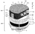
- FIG. 1 is a perspective view of the rotary electric machine 100.
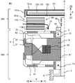
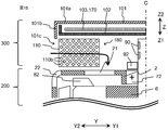
- FIG. 2 is a schematic cross-sectional view of the rotary electric machine 100 taken along a plane passing through the heat sink 110 and the axis C of the rotary shaft 4.
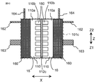
- FIG. 3 is a perspective view of one power module 160 and the heat sink 110.
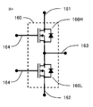
- FIG. 4 is a circuit diagram of a power semiconductor element provided in one power module 160
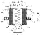
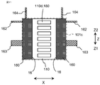
- FIG. 5 is a side view of the paired two power modules 160 and the heat sink 110 as viewed from the outside Y2 in the radial direction. is there.
- a direction parallel to the axis C of the rotating shaft 4 is defined as an axial direction Z, and one side Z1 of the axial direction is referred to as a front side Z1.
- the other side Z2 is referred to as the rear side Z2.
- the radial direction Y and the circumferential direction X are the radial direction and the circumferential direction with respect to the axis C of the rotary shaft 4.
- the rotating electric machine 100 includes a rotating electric machine body 200.
- the rotating electric machine main body 200 includes a stator 3 provided with windings of a plurality of phases, a rotor 6 arranged on a radially inner side Y1 of the stator 3, a rotary shaft 4 which rotates integrally with the rotor 6, and a stator. 3 and the rotor 6, and a bracket that rotatably supports the rotating shaft 4 is provided.
- the bracket is composed of the front side bracket 1 on the front side Z1 and the rear side bracket 2 on the rear side Z2.
- the front bracket 1 has a cylindrical outer peripheral wall and a disk-shaped side wall extending radially inward Y1 from the front side Z1 end of the outer peripheral wall, and the rotary shaft 4 is provided at the center of the side wall.
- a through hole is provided through which the front bearing 71 is fixed.
- the rear bracket 2 has a cylindrical outer peripheral wall and a disk-shaped side wall extending inward in the radial direction Y1 from the rear side Z2 end of the outer peripheral wall, and the rotary shaft 4 is provided at the center of the side wall.
- a through hole is provided through which the rear bearing 72 is fixed.
- the front side bracket 1 and the rear side bracket 2 are connected by a bolt 15 extending in the axial direction Z.
- the end of the rotary shaft 4 on the front side Z1 penetrates through the through hole of the front bracket 1 and projects further to the front side Z1 than the front bracket 1, and the pulley 9 is fixed to this projection.
- a belt is stretched between the pulley 9 and the pulley 9 fixed to the crankshaft of the engine (not shown), and the rotational driving force is transmitted between the rotary electric machine 100 and the engine.
- the rear side Z2 end of the rotary shaft 4 penetrates the through hole of the rear side bracket 2 and projects to the rear side Z2 more than the rear side bracket 2, and a pair of slip rings 90 are provided on this protruding part. ing.
- the pair of slip rings 90 are connected to the field winding 62 of the rotor 6.
- the rotor 6 includes a field winding 62 and a field iron core 61.
- the rotor 6 is of a Lundell type (also called a claw pole type).
- the field iron core 61 includes a cylindrical center portion, a front side claw portion extending from an end portion on the front side Z1 of the center portion to a radial outside Y2 of the center portion, and an end portion on the rear side Z2 of the center portion. And a rear side claw portion that extends to the outside Y2 in the radial direction of the center portion.
- the insulated copper wire of the field winding 62 is concentrically wound around the outer peripheral surface of the central portion of the field iron core 61.
- the front side claw portion and the rear side claw portion are alternately provided in the circumferential direction X, and have different magnetic poles.
- the front side claw portion and the rear side claw portion are provided in six or eight, respectively.
- the stator 3 is arranged so as to surround the rotor 6 with a minute gap, and has a cylindrical stator core 31 having slots, and a multi-phase winding wound around the slots of the stator core 31. 32, and.
- the plural-phase windings 32 are, for example, one set of three-phase windings, two sets of three-phase windings, one set of five-phase windings, or the like, and are set according to the type of the rotating electric machine.
- the multi-phase winding 32 has a front coil end portion protruding from the stator core 31 to the front side Z1, and a rear coil end portion protruding from the stator core 31 to the rear side Z2.
- the lead wires of the multi-phase windings 32 penetrate the rear bracket 2 and extend to the rear Z2 (not shown).
- the front bracket 1 and the rear bracket 2 are provided with a gap in the axial direction Z.
- the stator core 31 is sandwiched between the opening ends on the rear side Z2 of the front bracket 1 and the opening ends on the front side Z1 of the rear bracket 2 from both axial ends.
- a front side blower fan 81 having a plurality of blades is fixed to an end portion of the rotor 6 (field iron core 61) on the front side Z1, and a rear side Z2 end of the rotor 6 (field iron core 61) is fixed. Is attached with a rear side blower fan 82 having a plurality of blades, and they rotate integrally with the rotor 6.
- the rear bracket 2 is provided with a plurality of openings 22 (hereinafter, referred to as exhaust openings 22) dispersed in the circumferential direction at a portion on the radially outer side Y2 of the rear blower fan 82.
- a plurality of openings 21 (hereinafter, referred to as intake openings 21) are provided in a portion dispersed in the circumferential direction.
- the rotating electric machine 100 includes a power supply unit 300 that supplies electric power to the rotating electric machine main body 200.
- the power supply unit 300 is arranged on the rear side Z2 of the rotary electric machine main body 200 and is fixed to the rotary electric machine main body 200.
- the power supply unit 300 includes a plurality of power semiconductor elements, includes an inverter that performs DC/AC conversion between a DC power supply and windings of a plurality of phases, and a control circuit 170 that controls ON/OFF of the power semiconductor elements. ing.
- the inverter is composed of the power module 160 provided with the power semiconductor element.
- the power supply unit 300 also includes a heat sink 110 that is thermally connected to the heat sink fixing surface 16 of the power module 160, and a coolant flow path 180 through which a coolant flows in the arrangement space of the heat sink 110.
- the power supply unit 300 includes a pair of brushes (not shown) that come into contact with a pair of slip rings 90 provided on a protrusion of the rotary shaft 4 that protrudes from the rear bracket 2 to the rear Z2, and the brush and the slip ring 90.
- a power semiconductor element (not shown) for the field winding that turns on and off the power supplied to the field winding 62 via the field winding 62.
- the power semiconductor element (switching element) for the field winding is on/off controlled by the control circuit 170.
- a rotation sensor 92 for detecting rotation information of the rotary shaft 4 is provided on the rear side Z2 of the rotary shaft 4.
- a hall element, a resolver, a sensor IC, or the like is used as the rotation sensor 92.
- the rotation sensor 92 detects the rotation information of the rotary shaft 4 by magnetic induction or electromagnetic induction.
- the power supply unit 300 includes a cover 101.
- the cover 101 covers the rear side Z2 and the radially outer side Y2 of the control circuit 170, the power module 160, the heat sink 110, and the like.
- the cover 101 is formed in a bottomed tubular shape that opens to the front side Z1.
- the positive electrode power supply terminal 151 and the negative electrode power supply terminal 152 for connecting the inverter to the external DC power supply, and the control circuit 170 are connected to the external control device on the outer peripheral wall 101b of the cover 101 that covers the radially outer side Y2.
- a control connector 153 is provided for this purpose.
- a cover opening 101c is provided on the outer peripheral wall 101b of the cover 101, and is open to the outside. No opening is provided in the rear side bottom wall 101a of the cover 101 that covers the rear side Z2. The front side Z1 of the cover 101 is open, and the opening is covered by the rotary electric machine main body 200 (rear side bracket 2).
- the control circuit 170 includes a plate-shaped (disc-shaped in this example) circuit board 103.
- the control circuit 170 includes a case 102 that covers the circuit board 103.
- the circuit board 103 is composed of a printed board, a ceramic board, a metal board, or the like on which electronic components forming the control circuit 170 are mounted.
- the circuit board 103 is fixed to the case 102 by screws, heat caulking, rivets, bonding, or the like.
- the fixed points are arranged at intervals of 50 to 60 mm, for example. This interval is an example, and may be changed according to the vibration condition and the product shape.
- the circuit board 103 is arranged on the rear side Z2 of the rear side bracket 2 with a space.
- the circuit board 103 extends in the radial direction Y and the circumferential direction X.
- the surface of the circuit board 103 is orthogonal to the axial direction Z.
- the surface of the circuit board 103 may be inclined at an angle of, for example, 30 degrees or less with respect to the plane orthogonal to the axial direction Z.
- the case 102 covers the front side Z1 of the circuit board 103.
- the case 102 also includes a peripheral wall that covers the outer peripheral side of the circuit board 103.
- the rear side Z2 of the circuit board 103 is covered by the rear side bottom wall 101a of the cover 101.
- the case 102 is provided with an opening (not shown) through which a control connecting member 164 of the power module 160 described later penetrates.
- the control connection member 164 is connected to the circuit board 103.
- the rotary shaft 4 extends from the rear bracket 2 to the rear side Z2 from the front side Z1 surface of the circuit board 103 (immediately before the front side Z1 surface of the case 102 in this example). Therefore, the rotating shaft 4 does not penetrate the circuit board 103 and the case 102, and is arranged with a gap on the front side Z1 of the circuit board 103 and the case 102. According to this configuration, it is not necessary to provide the circuit board 103 and the case 102 with an opening for avoiding the rotation shaft 4. Therefore, the outer diameter of the circuit board 103 can be reduced, and the outer diameter of the power module 160 can be reduced in size and cost.
- the circuit board 103 may be provided with a through hole through which the rotary shaft 4 penetrates. Further, the circuit board 103 does not have to have a disc shape as long as it fits within a range overlapping the rear bracket 2 in the axial direction Z, and may be composed of two or more circuit boards. The materials of the circuit board may be different.
- the power supply unit 300 is connected to the positive side power semiconductor element 166H connected to the positive side of the DC power source and the negative side of the DC power source, as shown in FIG. 4, for one phase winding.
- One set of a series circuit in which the negative power semiconductor element 166L is connected in series is provided.
- a connection point where the positive power semiconductor element 166H and the negative power semiconductor element 166L are connected in series is connected to the winding of the corresponding phase.
- three sets of series circuits are provided when one set of three-phase windings is provided, and six sets of series circuits are provided when two sets of three-phase windings are provided.
- both or one of the positive and negative power semiconductor elements 166H and 166L may be respectively configured by two or more power semiconductor elements connected in parallel.
- Switching elements such as IGBT (Insulated Gate Bipolar Transistor) and power MOSFET (Power Metal Oxide Semiconductor Field Effect Transistor) are used for the power semiconductor element. These are used in inverters that drive devices such as motors, and control rated currents of several amps to several hundred amps. Silicon (Si), silicon carbide (SiC), gallium nitride (GaN), or the like may be used as the material of the power semiconductor element.
- IGBT Insulated Gate Bipolar Transistor
- MOSFET Power Metal Oxide Semiconductor Field Effect Transistor
- one power module 160 is provided with one series circuit of the positive power semiconductor element 166H and the negative power semiconductor element 166L. As shown in FIGS. 3 and 4, the power module 160 is connected to the positive electrode side connecting member 161 connected to the collector terminal of the positive power semiconductor element 166H and to the emitter terminal of the negative power semiconductor element 166L.
- the negative electrode side connecting member 162, the winding connecting member 163 connected to a connection point between the emitter terminal of the positive side power semiconductor element 166H and the collector terminal of the negative side power semiconductor element 166L, the positive side and And a control connection member 164 connected to the gate terminals and the like of the power semiconductor elements 166H and 166L on the negative electrode side.
- a metal such as copper or copper alloy having good conductivity and high thermal conductivity may be used. May be plated with a metal material such as Au, Ni or Sn. Further, the metal and plating materials of each terminal may be composed of two or more kinds. Note that one power module 160 may be provided with one power semiconductor element, or may be provided with three or more power semiconductor elements. The configurations of the connecting members and the like are changed according to the number of power semiconductor elements.
- the positive electrode side connecting member 161 is connected to the positive electrode side wiring member connected to the positive electrode side power supply terminal 151, and the negative electrode side connecting member 162 is connected to the positive electrode side wiring member connected to the negative electrode side power supply terminal 152.
- the connection member 163 is connected to a winding wiring member connected to the winding of the corresponding phase, and the control connection member 164 is connected to the control circuit 170.
- the power semiconductor element is bonded to the wiring pattern of the metal or ceramic substrate, the bus bar, etc. with a conductive material such as solder or silver paste.
- the metal substrate is made of a base material such as aluminum or copper.
- the ceramic substrate is made of alumina, aluminum nitride, silicon nitride or the like.
- the bus bar is made of iron, aluminum, copper or the like.
- the wiring pattern and bus bar are collectively referred to as a lead.
- the power module 160 has a heat sink fixing surface 16 to which the heat sink 110 is thermally connected.
- the power semiconductor element is fixed to one surface of the metal substrate, ceramic substrate, bus bar or the like, and the other surface of the metal substrate, ceramic substrate, bus bar or the like constitutes the heat sink fixing surface 16. doing.
- the heat sink fixing surface 16 may be provided on the same side as the surface of the metal substrate, the ceramic substrate, the bus bar or the like to which the power semiconductor element is fixed. Further, the two surfaces of the power module 160 which are opposite to each other may be the heat sink fixing surfaces 16, and the heat sink 110 may be thermally connected to each surface.
- a heat transfer material is interposed in the connection between the heat sink fixing surface 16 and the heat sink 110 in order to reduce the contact thermal resistance.
- an insulating material such as grease, an adhesive, a sheet or a gel, or a conductive member such as solder or silver paste is used as the heat transfer material.
- an insulating material is used as the heat transfer material.
- the power module 160 and the heat sink 110 are thermally connected via the heat transfer material, so that it is possible to reduce the number of members and bonding steps and reduce the thermal resistance.
- the leads and the heat sink 110 When the leads and the heat sink 110 have the same potential, they may be connected by a conductive member such as solder, or the leads joined to the power semiconductor element are mechanically pressed against the heat sink 110 by springs or screws. May be. By changing from joining to mechanical pressing, deterioration in temperature cycle and high temperature is reduced while reducing thermal resistance, and long-term reliability is improved. Further, the heat sink 110 may be integrated into a module with the power module 160.
- the power module 160 includes a sealing resin 165.
- the sealing resin 165 seals the power semiconductor element, the positive electrode side connecting member 161, the negative electrode side connecting member 162, the winding connecting member 163, the control connecting member 164, and other components.
- the sealing resin 165 include potting resins such as epoxy resin, silicone resin, urethane resin, coating materials for the surface of power semiconductor elements such as fluororesin, polybutylene terephthalate (PBT), polyphenylene sulfide (PPS), and polyether.
- a molding material such as ether ketone (PEEK) or acrylonitrile butadiene styrene (ABS) is used.
- the sealing resin 165 may be omitted as long as the power module 160 can be insulated and fixed by a method other than the sealing resin 165.
- the power module 160 and the heat sink 110 are arranged in the space between the rear bracket 2 and the circuit board 103 (in this example, the case 102) in the axial direction Z.
- the heat sink fixing surface 16 of the power module 160 extends in the radial direction Y and the axial direction Z.
- air as a coolant flows in the radial direction Y in the arrangement space of the heat sink 110.
- the refrigerant may be a medium other than air (for example, cooling water).
- the heat sink fixing surface 16 of the power module 160 extends in the radial direction Y and the axial direction Z, and the heat sink 110 is arranged on one side or the other side of the heat sink fixing surface 16 in the circumferential direction X. .. Therefore, it is possible to suppress the power module 160 and the heat sink 110 from extending in the circumferential direction X, and it is possible to suppress an increase in the layout area of the power module 160 and the heat sink 110 in the circumferential direction X. Therefore, it is possible to prevent the outer diameter of the power supply unit 300 from increasing due to the mounting of the power module 160 and the heat sink 110.
- the heat sink 110 is arranged on one side or the other side of the heat sink fixing surface 16 in the circumferential direction X. Since the coolant flow path 180 through which the coolant flows in the radial direction Y is provided in the arrangement space of the heat sink 110, the space between the rear bracket 2 and the circuit board 103 arranged at intervals in the axial direction Z is provided.
- the coolant flow channel 180 can be provided by utilizing it. Therefore, it is not necessary to reduce the layout area of the circuit board 103 in order to flow the refrigerant to the rear side Z2 of the power module 160.
- the refrigerant flows in the radial direction Y, the refrigerant can pass near the protrusion on the rear side Z2 of the rotating shaft 4 on the radially inner side Y1. Therefore, the slip ring 90 and the brush, the rotation sensor 92, and the rear bearing 72, which are provided near the protrusion on the rear side Z2 of the rotary shaft 4, can also be efficiently cooled.
- the heat sink fixing surface 16 is a flat surface and extends along a plane passing through the axis C.
- the heat sink fixing surface 16 may have irregularities or a curved surface as long as it extends in the radial direction Y and the axial direction Z. Further, the heat sink fixing surface 16 may be inclined at an angle of, for example, 30 degrees or less with respect to a plane passing through the axis C and intersecting with the heat sink fixing surface 16.
- the power module 160 is formed in a rectangular parallelepiped shape, and each of the connecting members 161 to 164 projects from the rectangular parallelepiped portion.
- the heat sink fixing surface 16 is one surface of a rectangular parallelepiped.
- Each side of the rectangular parallelepiped is arranged so as to be parallel or orthogonal to the axial direction Z.
- the width of the power module 160 in the circumferential direction X is smaller than the width in the radial direction Y and the width in the axial direction Z.
- each side of the rectangular parallelepiped may be arranged so as not to be parallel or orthogonal to the axial direction Z but to be inclined.
- the power module 160 may be formed in a shape other than the rectangular parallelepiped shape.
- the control connecting member 164 projects from the rear side Z2 surface of the power module 160 to the rear side Z2, and is connected to the circuit board 103 arranged on the rear side Z2 of the power module 160.
- the positive electrode side connecting member 161, the negative electrode side connecting member 162, and the winding connecting member 163 protrude from the surface of the power module 160 opposite to the heat sink fixing surface 16.
- the heat sink 110 is thermally connected to the heat sink fixing surface 16 of the power module 160.
- the heat sink 110 is arranged on one side or the other side of the heat sink fixing surface 16 in the circumferential direction X.
- the heat sink 110 has a role of radiating the heat generated when a current flows through the power semiconductor element and the conduction path and the heat coming from other components to the outside.
- the heat sink 110 is configured using a material having a thermal conductivity of 5 W/m ⁇ K or more, such as metal such as aluminum, aluminum alloy, copper, and copper alloy, ceramic, resin, or the like.
- the heat sink 110 includes a plate-shaped base portion 110a that is thermally connected to the heat sink fixing surface 16, and a plurality of protruding portions 110b that protrude from the base portion 110a to the side opposite to the heat sink fixing surface 16.
- the heat dissipation area can be increased by providing the plurality of protrusions 110b.
- each of the plurality of protrusions 110b is formed in a plate shape that extends in the circumferential direction X and the radial direction Y at intervals in the axial direction Z.
- the plurality of plate-shaped protrusions 110b are flat plates that extend in parallel to the circumferential direction X and the radial direction Y.
- the plurality of plate-shaped protrusions 110b need only extend in the circumferential direction X and the radial direction Y, and with respect to a plane parallel to the circumferential direction X and the radial direction Y (a plane orthogonal to the axial direction Z). For example, it may be inclined at an angle within 30 degrees.
- the base portion 110a extends in the radial direction Y and the axial direction Z, and is formed in a rectangular parallelepiped shape having a surface having the same area as the heat sink fixing surface 16 of the power module 160.
- the width of the base portion 110a in the circumferential direction X is shorter than the width in the radial direction Y and the width in the axial direction Z.
- the protrusion 110b is formed in a rectangular flat plate shape.
- the base portion 110a may be formed in a shape other than a rectangular parallelepiped shape as long as it has a surface fixed to the heat sink fixing surface 16, and the protrusion 110b is formed in a plate shape other than a rectangular flat plate shape. May be. Further, if heat dissipation can be ensured, the heat sink 110 may not be provided with the plurality of protrusions 110b.
- the width of the entire outer shape of the power module 160 and the heat sink 110 excluding the connecting members in the circumferential direction X is shorter than the width in the radial direction Y and the width in the axial direction Z. Therefore, by disposing the heat sink fixing surface 16 so as to extend in the radial direction Y and the axial direction Z, the arrangement area of the power module 160 and the heat sink 110 in the circumferential direction X can be reduced.
- two power modules 160 are arranged with their heat sink fixing surfaces 16 facing each other in the circumferential direction X. Between the two power modules 160, one or more heat sinks 110 are arranged, and a refrigerant flow path 180 through which the refrigerant flows in the radial direction is formed.
- two heat sinks 110 are arranged between the two power modules 160, and one heat sink 110 is thermally connected to each of the heat sink fixing surfaces 16 of the two power modules 160.
- the space between the two heat sinks 110 serves as a refrigerant flow path 180 in which the refrigerant flows in the radial direction.
- the two power modules 160 can share the coolant passage 180 through which the coolant flows in common. Further, since the two power modules 160 can be arranged close to each other in the circumferential direction X, the layout area of the power module 160 and the heat sink 110 in the circumferential direction X can be reduced, and the power supply unit 300 can be downsized.
- control circuit 170 can be arranged on the rear side Z2 of each power module 160, and the control connection member 164 from each power module 160 to the rear side Z2. It can be extended and connected to the control circuit 170.
- At least two power modules 160 may be arranged with the heat sink fixing surfaces 16 facing each other, and even in one power module 160 that is not paired, the heat sink fixing surfaces 16 extend in the radial direction Y and the axial direction Z. It may be arranged as follows.
- a cover opening 101c is provided in the portion of the cover 101 on the radially outer side Y2 of the heat sink 110. Therefore, the air as the refrigerant can be concentratedly flown in the flow path between the two heat sinks 110, and the cooling efficiency can be improved.
- a plurality of cover openings 101c may be provided according to the number of heat sinks 110 and power modules 160.
- the opening area of the cover opening portion 101c is equal to the area where the two power modules 160 and the heat sink 110 are arranged.
- the end surfaces of the two heat sinks 110 and the power module 160 on the radially outer side Y2 are made equal to the radial positions of the cover opening 101c so that the gaps between the cover opening 101c and the two heat sinks 110 and the power module 160 become small. It is arranged so that.
- the gap area between the outer edge of the cover opening 101c and the end surface of the two heat sinks 110 and the radially outer side Y2 of the power module 160 is larger than the opening area of the space between the two heat sinks 110 on the radially outer side Y2. It is getting smaller. Therefore, the air can efficiently flow in the space between the two heat sinks 110.
- the case 102 is arranged on the rear side Z2 of the arrangement space of the heat sink 110, and the rear bracket 2 is arranged on the front side Z1 of the arrangement space of the heat sink 110. And the cooling efficiency can be improved.
- the coolant flow path 180 air as a coolant passes through the cover opening 101c of the cover 101 and is sucked from the outside, and then the space for disposing the heat sink 110 is changed. It flows to the inside Y1 in the radial direction, and then flows to the front side Z1 through the intake opening 21 on the rear side Z2 of the rear bracket 2. The air may flow in the opposite direction.
- FIG. 6 is a schematic sectional view of rotary electric machine 100 according to the present embodiment, taken along a plane passing through heat sink 110 and axis C of rotating shaft 4.
- rotating electric machine 100 includes flow path forming member 104 that forms refrigerant flow path 180, and flow path forming member 104 includes power module 160 in axial direction Z and It is arranged between the heat sink 110 and the rear bracket 2.
- the flow path forming member 104 is arranged on the front side Z1 of the arrangement space of the heat sink 110, the refrigerant can be collected in the arrangement space of the heat sink 110, and the cooling efficiency can be improved.
- the flow path forming member 104 is formed in a plate shape extending in the radial direction Y and the circumferential direction X, and is formed in a region including the region where the heat sink 110 is arranged when viewed in the axial direction Z. It is arranged. Further, the flow path constituent member 104 is arranged so as to cover a part of the rear side Z2 of the rear bracket 2 on the rear side Z2 of the intake opening 21. According to this configuration, it is possible to prevent the refrigerant from being sucked into the intake opening portion 21 before reaching the end portion on the radially inner side Y1 of the arrangement space of the heat sink 110. Even if a part of the intake opening 21 is covered, the refrigerant flows through the intake openings 21 distributed in the circumferential direction X, so that the flow is not significantly hindered.
- the flow path forming member 104 includes the rear side Z2 of the rear bracket 2 on the rear side Z2. May be arranged so as not to cover. In this case, the pressure loss generated in the refrigerant flow channel 180 can be reduced, and the flow rate of the refrigerant passing through the refrigerant flow channel 180 can be increased. Further, the flow path forming member 104 may have holes.
- Embodiment 3 Next, rotary electric machine 100 according to the third embodiment will be described. The description of the same components as those in the first embodiment is omitted.
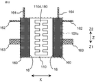
- 7 and 8 are side views of the paired two power modules 160 and the heat sink 110 according to the present embodiment as viewed from the outer side Y2 in the radial direction.
- the two power modules 160 are arranged with the heat sink fixing surfaces 16 facing each other in the circumferential direction X.
- the heat sink 110 is thermally connected to each of the two heat sink fixing surfaces 16, and a coolant passage 180 through which air as a coolant flows in the radial direction Y is formed between the two heat sinks 110.
- Each of the two heat sinks 110 has a plate-shaped base portion 110a thermally connected to the heat sink fixing surface 16, and a plurality of protruding portions 110b protruding from the base portion 110a to the side opposite to the heat sink fixing surface 16. Is equipped with.
- each of the plurality of protrusions 110b is formed in a plate shape that is spaced from each other in the axial direction Z and extends in the circumferential direction X and the radial direction Y.
- the plurality of protrusions 110b of one heat sink 110 and the plurality of protrusions 110b of the other heat sink 110 are arranged alternately in the axial direction Z. That is, the positions of the protruding portions 110b in the axial direction Z are staggered between the one heat sink 110 and the other heat sink 110.
- the tip of the protruding portion 110b of the one heat sink 110 is located in the recess of the other heat sink 110, so that the refrigerant easily flows through the tip of the protruding portion 110b, and the cooling efficiency can be improved. ..
- the protruding portion 110b of one heat sink 110 and the protruding portion 110b of the other heat sink 110 are arranged at intervals in the circumferential direction X.
- the protruding portion 110b of the one heat sink 110 and the protruding portion 110b of the other heat sink 110 are arranged so as to be spaced from each other and overlap in the axial direction Z.
- the protrusion height of the protrusion 110b can be increased to increase the heat dissipation area and enhance the cooling efficiency.
- the two power modules 160 may be brought close to each other in the circumferential direction X without increasing the projecting height of the projecting portion 110b. In this case, the arrangement area of the power module 160 and the heat sink 110 in the circumferential direction X is reduced.
- the power supply unit 300 can be downsized.
- Embodiment 4 Next, rotating electric machine 100 according to Embodiment 4 will be described. The description of the same components as those in the first embodiment is omitted.
- 9 and 10 are side views of the paired two power modules 160 and the heat sink 110 according to the present embodiment as viewed from the outer side Y2 in the radial direction.
- the end portions of the two heat sinks 110 on the front side Z1 are fixed to each other by the front side fixing member 112a, and the two heat sinks 110 are fixed.
- the respective ends of the rear side Z2 are fixed to each other by the rear side fixing member 112b.
- the front side fixing member 112a closes the opening on the front side Z1 in the space between the two heat sinks 110
- the rear side fixing member 112b closes the opening on the rear side Z2 in the space between the two heat sinks 110.
- the front side fixing member 112a and the rear side fixing member 112b can improve the mutual arrangement accuracy of the two power modules 160 and the heat sink 110. Further, the refrigerant can be prevented from leaking from the arrangement space of the heat sink 110 to the front side Z1 and the rear side Z2, and the cooling performance can be improved.
- Each fixing member 112a, 112b may be made of a resin material such as polybutylene terephthalate (PBT), polyphenylene sulfide (PPS), and ether ether ketone (PEEK), or iron, aluminum, copper, or the like. It may be made of pure metal or an alloy made of iron, aluminum, copper or the like.
- the fixing members 112a and 112b are fixed to the heat sink 110 by, for example, screwing, bonding, caulking, welding, or the like.
- each fixing member 112a, 112b is made of a material having a high thermal conductivity, for example, a thermal conductivity of 5 W/m2 ⁇ K or more
- the temperatures of the two heat sinks 110 facing each other should be equalized.
- the power modules 160 operate at different timings and have different energization timings, the temperature of the power semiconductor elements mounted on the power module 160 may fluctuate and the temperature of the heat sink 110 may fluctuate, but the fluctuation is suppressed. can do.
- the two heat sinks 110 can be fixed by the fixing member on one side, only one of the front side fixing member 112a and the rear side fixing member 112b may be provided.
- the refrigerant can pass through the refrigerant flow path 180 sufficiently, all the openings on the front side Z1 or the rear side Z2 of the space between the two heat sinks 110 need not be blocked by the fixing member. Of course, a part of the opening may be closed by the fixing member.
- the two heat sinks 110 may be fixed to each other in a state where the plate-shaped fixing member 112c is sandwiched by the tip ends of the protrusions 110b of the two heat sinks 110.
- the plate-shaped fixing member 112c can improve the mutual arrangement accuracy of the two power modules 160 and the heat sink 110. Further, since the opening on one side or the other side in the circumferential direction X of the space between the two plate-shaped projecting portions 110b adjacent to each other in the axial direction Z is closed by the plate-shaped fixing member 112c, the two plate-shaped is formed.
- the refrigerant that has flowed into the space between the protruding portions 110b can be prevented from leaking to the outside on the way, and the cooling performance can be improved.
- the plate-shaped fixing member 112c extends in the axial direction Z and the radial direction Y.
- Embodiment 5 Next, rotating electric machine 100 according to Embodiment 5 will be described. The description of the same components as those in the first embodiment is omitted.
- 11 and 12 are side views of the paired two power modules 160 and the heat sink 110 according to the present embodiment as seen from the outer side Y2 in the radial direction.
- the two power modules 160 are arranged with the heat sink fixing surfaces 16 facing each other in the circumferential direction X.
- One heat sink 110 is arranged between the two power modules 160, and one heat sink 110 is thermally connected to the heat sink fixing surfaces 16 of the two power modules 160, and one heat sink 110 is arranged in the radial direction Y.
- a coolant passage 110d is formed therethrough.
- the mutual placement accuracy of the two power modules 160 can be improved. Further, the refrigerant can be prevented from leaking out of the flow path formed in the heat sink 110 on the way, and the cooling performance can be improved. In addition, temperature variations between the two power modules 160 can be suppressed.
- a plurality of through holes 110d penetrating in the radial direction Y are arranged at intervals in the axial direction Z at the center of the heat sink 110 in the circumferential direction X.
- Each through hole 110d is formed in a rectangular tubular shape.
- a plurality of through-holes 110d provided in the central portion of the heat sink 110 in the circumferential direction X are connected in the axial direction Z with respect to the example of FIG.
- the number and shape of the through holes 110d (flow paths) penetrating in the radial direction Y may be set arbitrarily, and may be, for example, a plurality of cylindrical through holes arranged in a grid pattern.
- FIG. 13 to 15 are schematic cross-sectional views of the rotary electric machine 100 according to the present embodiment taken along a plane passing through the heat sink 110 and the axis C of the rotary shaft 4.
- the plate-shaped protrusion 110b extending in the circumferential direction X and the radial direction Y does not have to be continuous in the radial direction Y and may be located at any position in the radial direction. It may be divided into a plurality of Ys. According to this configuration, the surface area of the protrusion 110b can be increased by the amount of the break caused by the division, and the cooling performance can be improved. Further, at the break, the refrigerant can move to the front side Z1 and the cooling performance can be improved.
- the positions in the radial direction Y of the cuts of the plate-shaped protrusion 110b may not be the same between the protrusions 110b, and the diameter may be increased toward the front side Z1. You may move to the direction inner side Y1.
- the protrusion 110b does not have to be formed in a plate shape extending in the circumferential direction X and the radial direction Y, and is formed in a columnar shape having an arbitrary cross-sectional shape such as a square shape. May be done.
- the plurality of columnar protrusions 110b may be arranged in an arbitrary pattern such as a lattice pattern so that the coolant flows in the radial direction Y. With this configuration, the surface area of the protrusion 110b can be increased, and the refrigerant can be moved to the front side Z1 as well, so that the cooling performance can be improved.
- the projecting portion 110b is not limited to a quadrangular prism, and may be a triangular prism, a cylinder, or any other polygonal column, and may be a column shape or a cone shape.
- the plurality of protrusions 110b are not limited to the illustrated shapes and arrangements as long as they protrude from the base 110a to the side opposite to the heat sink fixing surface 16 and the refrigerant flows in the radial direction Y. May be
Landscapes
- Engineering & Computer Science (AREA)
- Power Engineering (AREA)
- Microelectronics & Electronic Packaging (AREA)
- Motor Or Generator Cooling System (AREA)
Abstract
パワーモジュール及びヒートシンクの搭載によって、回転電機の外径が拡大することを抑制できる回転電機を提供する。ヒートシンク固定面(16)は、径方向(Y)及び軸方向(Z)に延在し、パワーモジュール(160)は、2つ以上設けられ、2つのパワーモジュール(160)が、ヒートシンク固定面(16)を周方向(X)に互いに対向させて配置され、2つのパワーモジュール(160)の間に、1つ以上のヒートシンク(110)が配置されると共に、冷媒が径方向(Y)に流れる流路(180)が形成されている回転電機(100)。
Description
本願は、回転電機に関するものである。
回転電機は、回転子及び固定子から構成される回転電機本体部と、回転電機本体部に電力を供給するインバータ及び制御回路から構成される電力供給ユニットを備えている。省スペース性と搭載性の容易さ、また、回転電機本体部とインバータとを接続する配線ハーネスの短縮等から、回転電機本体部と電力供給ユニットとを一体化させた機電一体型の回転電機が開発されている。
例えば、特許文献1及び特許文献2に開示されている回転電機において、インバータは回転電機の端に取り付けられている。インバータのヒートシンクにはフィンが形成されており、回転子の端部に装着された送風ファンにより発生した冷却風がフィンを通過することでインバータを冷却している。
しかしながら、特許文献1の技術では、パワーモジュールのヒートシンク及びそのフィンは、周方向及び径方向に延在しており、フィンは軸方向に突出している。よって、パワーモジュール、ヒートシンク、及びフィンは、周方向に広がって配置されており、周方向の配置面積が大きくなっている。そのため、複数個のパワーモジュールを搭載しようとすると、電力供給ユニットの外径が大きくなる課題があった。
特許文献2の技術では、パワーモジュールのヒートシンク及びフィンは、周方向及び軸方向に延在しており、フィンは径方向内側に突出している。よって、パワーモジュール、ヒートシンク、及びフィンは、周方向に広がって配置されており、周方向の配置面積が大きくなっている。そのため、複数個のパワーモジュールを搭載しようとすると、電力供給ユニットの外径が大きくなる課題があった。
また、特許文献2の技術では、冷却風を、回転軸付近を軸方向に流す必要があるため、冷却効率を向上させるためには、電力供給ユニットの軸方向の端部に、開口部を設ける必要があり、制御回路等の部品の配置が制限される。
例えば、回転電機を、自動車のエンジンルームに搭載する場合、限られた空間に設置できることが求められている。回転電機の外径の制約がある場合は、パワーモジュール及びヒートシンクの搭載により、回転電機の外径が拡大することを抑制する必要がある。
そこで、パワーモジュール及びヒートシンクの搭載によって、回転電機の外径が拡大することを抑制することができる回転電機が望まれる。
本願に係る回転電機は、
複数相の巻線を備えた固定子と、
前記固定子の径方向内側に配置された回転子と、
前記回転子と一体回転する回転軸と、
前記固定子及び前記回転子を収容すると共に、前記回転軸を回転可能に支持するブラケットと、
前記巻線への通電をオンオフする電力用半導体素子を設けたパワーモジュールと、
前記パワーモジュールのヒートシンク固定面に熱的に接続されたヒートシンクと、
前記電力用半導体素子を制御する制御回路と、を備え、
前記ヒートシンク固定面は、径方向及び軸方向に延在し、
前記パワーモジュールは、2つ以上設けられ、
2つの前記パワーモジュールが、前記ヒートシンク固定面を周方向に互いに対向させて配置され、前記2つのパワーモジュールの間に、1つ以上の前記ヒートシンクが配置されると共に、冷媒が径方向に流れる流路が形成されているものである。
本願に係る回転電機によれば、パワーモジュールのヒートシンク固定面は、径方向及び軸方向に延在し、ヒートシンクは、ヒートシンク固定面の周方向の一方側又は他方側に配置される。2つのパワーモジュールが、ヒートシンク固定面を周方向に互いに対向させて配置され、2つのパワーモジュールの間に、1つの以上のヒートシンクが配置されると共に、冷媒が径方向に流れる流路が形成されている。よって、2つのパワーモジュールで、ヒートシンクの配置空間及び冷媒流路を共通化し、集約することができる。また、2つのパワーモジュールを、周方向に対向して配置できる。よって、パワーモジュール及びヒートシンクの周方向の配置面積が大きくなることを抑制でき、パワーモジュール及びヒートシンクの搭載によって、回転電機の外径が拡大することを抑制できる。
以下、本願に係る回転電機の好適な実施の形態につき図面を用いて説明する。各図において同一、または相当する部分については、同一符号を付して説明する。なお、各図間の図示では、対応する各構成部のサイズ及び縮尺は、それぞれ独立している。
1.実施の形態1
実施の形態1に係る回転電機100について図面を参照して説明する。図1は、回転電機100の斜視図である。図2は、回転電機100を、ヒートシンク110及び回転軸4の軸心Cを通る平面で切断した模式的な断面図である。図3は、1つのパワーモジュール160及びヒートシンク110の斜視図である。図4は、1つのパワーモジュール160に設けられた電力用半導体素子の回路図であり、図5は、対にされた2つのパワーモジュール160及びヒートシンク110を径方向外側Y2から見た側面図である。
実施の形態1に係る回転電機100について図面を参照して説明する。図1は、回転電機100の斜視図である。図2は、回転電機100を、ヒートシンク110及び回転軸4の軸心Cを通る平面で切断した模式的な断面図である。図3は、1つのパワーモジュール160及びヒートシンク110の斜視図である。図4は、1つのパワーモジュール160に設けられた電力用半導体素子の回路図であり、図5は、対にされた2つのパワーモジュール160及びヒートシンク110を径方向外側Y2から見た側面図である。
本願において、回転軸4の軸心Cに平行な方向を軸方向Zと定義し、軸方向の一方側Z1をフロント側Z1と称し、軸方向の一方側Z1とは反対側である軸方向の他方側Z2をリア側Z2と称する。径方向Y及び周方向Xは、回転軸4の軸心Cについての径方向及び周方向である。
<回転電機本体部200>
回転電機100は、回転電機本体部200を備えている。回転電機本体部200は、複数相の巻線を備えた固定子3と、固定子3の径方向内側Y1に配置された回転子6、回転子6と一体回転する回転軸4と、固定子3及び回転子6を収容すると共に、回転軸4を回転可能に支持するブラケットと、を備えている。
回転電機100は、回転電機本体部200を備えている。回転電機本体部200は、複数相の巻線を備えた固定子3と、固定子3の径方向内側Y1に配置された回転子6、回転子6と一体回転する回転軸4と、固定子3及び回転子6を収容すると共に、回転軸4を回転可能に支持するブラケットと、を備えている。
本実施の形態では、ブラケットは、フロント側Z1のフロント側ブラケット1及びリア側Z2のリア側ブラケット2から構成されている。フロント側ブラケット1は、円筒状の外周壁と、外周壁のフロント側Z1端部から径方向内側Y1に延びた円板状の側壁とを有しており、側壁の中心部に回転軸4が貫通し、フロント側ベアリング71が固定される貫通孔が設けられている。リア側ブラケット2は、円筒状の外周壁と、外周壁のリア側Z2端部から径方向内側Y1に延びた円板状の側壁とを有しており、側壁の中心部に回転軸4が貫通し、リア側ベアリング72が固定される貫通孔が設けられている。フロント側ブラケット1とリア側ブラケット2は、軸方向Zに延びたボルト15によって連結されている。
回転軸4のフロント側Z1の端部は、フロント側ブラケット1の貫通孔を貫通して、フロント側ブラケット1よりもフロント側Z1に突出しており、この突出部にプーリ9が固定されている。プーリ9と、エンジンのクランクシャフトに固定されたプーリ9との間にベルトが掛け渡され(不図示)、回転電機100とエンジンとの間で、回転駆動力の伝達を行う。
回転軸4のリア側Z2の端部は、リア側ブラケット2の貫通孔を貫通して、リア側ブラケット2よりもリア側Z2に突出しており、この突出部に一対のスリップリング90が設けられている。一対のスリップリング90は、回転子6の界磁巻線62に接続されている。
回転子6は、界磁巻線62と界磁鉄心61とを備えている。回転子6は、ランデル型(クローポール型ともいう)とされている。界磁鉄心61は、円筒状の中心部と、中心部のフロント側Z1の端部から中心部の径方向外側Y2まで延びたフロント側の爪部と、中心部のリア側Z2の端部から中心部の径方向外側Y2まで延びたリア側の爪部と、を備えている。界磁巻線62の絶縁処理された銅線は、界磁鉄心61の中心部の外周面に同心状に巻回されている。フロント側の爪部とリア側の爪部とは、周方向Xに交互に設けられており、互いに異なる磁極となる。例えば、フロント側の爪部とリア側の爪部は、それぞれ6個又は8個設けられる。
固定子3は、微小な隙間をあけて回転子6を取り囲むよう配設され、スロットを設けた円筒状の固定子鉄心31と、固定子鉄心31のスロットに巻装された複数相の巻線32と、を備えている。複数相の巻線32は、例えば、1組の3相巻線、2組の3相巻線、又は1組の5相巻線等とされ、回転電機の種類に応じて設定される。
複数相の巻線32は、固定子鉄心31からフロント側Z1に突出したフロント側コイルエンド部、固定子鉄心31からリア側Z2に突出したリア側コイルエンド部を有している。複数相の巻線32のリード線は、リア側ブラケット2を貫通して、リア側Z2に延びている(不図示)。
フロント側ブラケット1とリア側ブラケット2とは、軸方向Zに間隔を空けて設けられている。固定子鉄心31は、フロント側ブラケット1のリア側Z2の開口端部とリア側ブラケット2のフロント側Z1の開口端部とにより軸方向両端から挟持されている。
回転子6(界磁鉄心61)のフロント側Z1の端部には、複数のブレードを有するフロント側送風ファン81が固定され、回転子6(界磁鉄心61)のリア側Z2の端部には、複数のブレードを有するリア側送風ファン82が取り付けられ、それらは、回転子6と一体回転する。
リア側ブラケット2は、リア側送風ファン82の径方向外側Y2の部分に、周方向に分散して複数の開口部22(以下、排気開口部22と称す)を設けており、リア側Z2の部分に、周方向に分散して複数の開口部21(以下、吸気開口部21と称す)を設けている。
<電力供給ユニット300>
回転電機100は、回転電機本体部200に電力を供給する電力供給ユニット300を備えている。電力供給ユニット300は、回転電機本体部200のリア側Z2に配置され、回転電機本体部200に固定されている。電力供給ユニット300は、複数の電力用半導体素子を有し、直流電源と複数相の巻線との間で直流交流変換を行うインバータと、電力用半導体素子をオンオフ制御する制御回路170とを備えている。本実施の形態では、インバータは、電力用半導体素子を設けたパワーモジュール160により構成されている。また、電力供給ユニット300は、パワーモジュール160のヒートシンク固定面16に熱的に接続されたヒートシンク110と、ヒートシンク110の配置空間において、冷媒が流れる冷媒流路180と、を備えている。
回転電機100は、回転電機本体部200に電力を供給する電力供給ユニット300を備えている。電力供給ユニット300は、回転電機本体部200のリア側Z2に配置され、回転電機本体部200に固定されている。電力供給ユニット300は、複数の電力用半導体素子を有し、直流電源と複数相の巻線との間で直流交流変換を行うインバータと、電力用半導体素子をオンオフ制御する制御回路170とを備えている。本実施の形態では、インバータは、電力用半導体素子を設けたパワーモジュール160により構成されている。また、電力供給ユニット300は、パワーモジュール160のヒートシンク固定面16に熱的に接続されたヒートシンク110と、ヒートシンク110の配置空間において、冷媒が流れる冷媒流路180と、を備えている。
電力供給ユニット300は、リア側ブラケット2からリア側Z2に突出した回転軸4の突出部に設けられた一対のスリップリング90に接触する一対のブラシ(不図示)と、ブラシ及びスリップリング90を介して界磁巻線62に供給する電力をオンオフする界磁巻線用の電力用半導体素子(不図示)とを備えている。界磁巻線用の電力用半導体素子(スイッチング素子)は、制御回路170によりオンオフ制御される。また、回転軸4のリア側Z2の突出部には、回転軸4の回転情報を検出する回転センサ92が備えられている。回転センサ92には、ホール素子、レゾルバ、センサIC等が用いられる。回転センサ92は磁気誘導又は電磁誘導によって回転軸4の回転情報を検出している。
電力供給ユニット300は、カバー101を備えている。カバー101は、制御回路170、パワーモジュール160、及びヒートシンク110等のリア側Z2及び径方向外側Y2を覆っている。カバー101は、フロント側Z1に開口する有底筒状に形成されている。径方向外側Y2を覆うカバー101の外周壁101bには、インバータを外部の直流電源に接続するための正極側電源端子151及び負極側電源端子152、並びに制御回路170を外部の制御装置に接続するための制御用コネクタ153が設けられている。
カバー101の外周壁101bには、カバー開口部101cが設けられており、外側に開口している。リア側Z2を覆うカバー101のリア側底壁101aには、開口部が設けられていない。カバー101のフロント側Z1は開口しており、開口部は、回転電機本体部200(リア側ブラケット2)により覆われている。
制御回路170は、板状(本例では、円板状)の回路基板103を備えている。制御回路170は、回路基板103を覆うケース102を備えている。回路基板103は、制御回路170を構成する電子部品が実装されたプリント基板、セラミック基板、金属基板等により構成されている。特に、車載機器においては高い振動耐久性が必要なため、回路基板103は、ケース102に、ねじ、熱加締め、リベット、接着等により固定されている。固定点は、例えば50~60mm間隔で配置されている。この間隔は一例であり、振動条件及び製品形状に合わせて変えられてもよい。
回路基板103は、リア側ブラケット2のリア側Z2に間隔を空けて配置されている。回路基板103は、径方向Y及び周方向Xに延在している。本実施の形態では、回路基板103の表面は、軸方向Zに直交している。なお、回路基板103の表面は、軸方向Zに直交する平面に対して、例えば、30度以内の角度で傾いていてもよい。ケース102は、回路基板103のフロント側Z1を覆っている。また、ケース102は、回路基板103の外周側を覆う周壁を備えている。回路基板103のリア側Z2は、カバー101のリア側底壁101aにより覆われている。
ケース102は、後述するパワーモジュール160の制御用接続部材164が貫通する開口部(不図示)が設けられている。制御用接続部材164は、回路基板103に接続される。
回転軸4は、リア側ブラケット2から回路基板103のフロント側Z1の面(本例ではケース102のフロント側Z1の面の直前)まで、リア側Z2に延出している。よって、回転軸4は、回路基板103及びケース102を貫通しておらず、回路基板103及びケース102のフロント側Z1に隙間を空けて配置されている。この構成によれば、回路基板103及びケース102に、回転軸4をよけるための開口部を設ける必要がなくなる。よって、回路基板103の外径を減少させ、パワーモジュール160の外径を小型化、低コスト化することができる。
なお、リア側ブラケット2と軸方向Zに見て重複する範囲内に電子部品を配置できれば、回路基板103に回転軸4が貫通する貫通孔が設けられてもよい。また、回路基板103は、リア側ブラケット2と軸方向Zに見て重複する範囲内に収まれば、円板状でなくてもよく、2枚以上の回路基板により構成されてもよく、それぞれの回路基板の材料が異なっていてもよい。
電力供給ユニット300は、1つの相の巻線に対して、図4に示すような、直流電源の正極側に接続される正極側の電力用半導体素子166Hと、直流電源の負極側に接続される負極側の電力用半導体素子166Lとが直列接続された直列回路を1セット設けている。正極側の電力用半導体素子166Hと負極側の電力用半導体素子166Lとが直列接続されている接続点が、対応する相の巻線に接続される。例えば、1組の3相の巻線が設けられる場合は、3セットの直列回路が設けられ、2組の3相の巻線が設けられる場合は、6セットの直列回路が設けられる。なお、正極側及び負極側の電力用半導体素子166H、166Lの双方又は一方が、それぞれ、並列に接続された2つの以上の電力用半導体素子により構成されてもよい。
電力用半導体素子には、IGBT(Insulated Gate Bipolar Transistor)、パワーMOSFET(Power Metal Oxide Semiconductor Field Effect Transistor)等のスイッチング素子が用いられる。これらは、モータなどの機器を駆動するインバータに用いられるもので、数アンペアから数百アンペアの定格電流を制御するものである。電力用半導体素子の材料として、シリコン(Si)、シリコンカーバイド(SiC)、ガリウムナイトライド(GaN)などが用いられてもよい。
本実施の形態では、1つのパワーモジュール160は、正極側の電力用半導体素子166Hと負極側の電力用半導体素子166Lとの1つの直列回路を設けている。図3及び図4に示すように、パワーモジュール160は、正極側の電力用半導体素子166Hのコレクタ端子に接続された正極側接続部材161と、負極側の電力用半導体素子166Lのエミッタ端子に接続された負極側接続部材162と、正極側の電力用半導体素子166Hのエミッタ端子と負極側の電力用半導体素子166Lのコレクタ端子との接続点に接続された巻線接続部材163と、正極側及び負極側の電力用半導体素子166H、166Lのゲート端子等に接続された制御用接続部材164と、を備えている。正極側接続部材161、負極側接続部材162、巻線接続部材163、制御用接続部材164には、導電性が良好で熱伝導率の高い銅または銅合金などの金属を用いてもよく、表面はAu、Ni、Snなどの金属材料でめっきされていてもよい。また、各端子の金属及びめっきの材質は、2種類以上で構成されてもよい。なお、1つのパワーモジュール160には、1つの電力用半導体素子が設けられてもよく、或いは3つ以上の電力用半導体素子が設けられてもよい。電力用半導体素子の数に合わせて、接続部材等の構成が変更される。
正極側接続部材161は、正極側電源端子151に接続される正極側配線部材に接続され、負極側接続部材162は、負極側電源端子152に接続される正極側配線部材に接続され、巻線接続部材163は、対応する相の巻線に接続される巻線配線部材に接続され、制御用接続部材164は、制御回路170に接続される。
電力用半導体素子は、金属基板又はセラミック基板の配線パターン、バスバー等に、はんだ、銀ペースト等の導電性材料で接合されている。金属基板は、アルミ、銅等のベース材料で構成される。セラミック基板は、アルミナ、窒化アルミ、窒化ケイ素等で構成される。バスバーは、鉄、アルミ、銅等で構成される。配線パターン及びバスバーを合わせてリードと称す。
パワーモジュール160は、ヒートシンク110が熱的に接続されるヒートシンク固定面16を有している。本実施の形態では、電力用半導体素子は、金属基板、セラミック基板、バスバー等の一方側の面に固定され、金属基板、セラミック基板、バスバー等の他方側の面は、ヒートシンク固定面16を構成している。なお、電力用半導体素子が固定される金属基板、セラミック基板、バスバー等の面と同じ側に、ヒートシンク固定面16が設けられてもよい。また、互いに反対側になるパワーモジュール160の2つの面が、ヒートシンク固定面16とされてもよく、それぞれの面に、ヒートシンク110が熱的に接続されてもよい。
本実施の形態では、ヒートシンク固定面16とヒートシンク110と間の接続には、接触熱抵抗を低減するため、伝熱材が介在している。金属基板、セラミック基板の場合は、伝熱材には、例えばグリース、接着剤、シート、ゲル等の絶縁性を有する材料、又ははんだ、銀ペースト等の導電性部材が用いられる。ヒートシンク110との絶縁が必要なリードの場合は、伝熱材には、絶縁性を有する材料が用いられる。これらにより、パワーモジュール160とヒートシンク110が伝熱材を介して熱的に接続されるため、部材及び接合工程を削減し熱抵抗を低減できる。
リードとヒートシンク110が同電位の場合は、はんだ等の導電性部材で接続してもよく、或いは、電力用半導体素子に接合されたリードを、ばね又はねじ等によりヒートシンク110に機械的に押圧させてもよい。接合から機械的な押圧に変えることで、熱抵抗を低減しつつ、温度サイクル及び高温での劣化が軽減され、長期信頼性が向上する。また、ヒートシンク110は、パワーモジュール160と一体的にモジュール化されていてもよい。
パワーモジュール160は、封止樹脂165を備えている。封止樹脂165は、電力用半導体素子、正極側接続部材161、負極側接続部材162、巻線接続部材163、制御用接続部材164、及びその他の構成部品を封止する。封止樹脂165には、例えばエポキシ樹脂、シリコーン樹脂、ウレタン樹脂等のポッティング樹脂、フッ素樹脂等の電力用半導体素子の表面のコーティング材料、ポリブチレンテレフタレート(PBT)、ポリフェニレンサルファイド(PPS)、ポリエーテルエーテルケトン(PEEK)、アクリロニトリルブタジエンスチレン(ABS)等の成形材料が用いられる。封止樹脂165によって電力用半導体素子等の構成部品を覆うことで、例えば、異物が混入した場合、塩、泥等が入った水等がかかった場合でも絶縁性を確保することができる。また、エポキシ樹脂等の硬度が高い材料を使うことで、部品を固定でき耐振性を向上できる。なお、封止樹脂165以外の方法でパワーモジュール160を絶縁し固定できれば、封止樹脂165はなくてもよい。
<冷却機構の配置構成>
パワーモジュール160及びヒートシンク110は、軸方向Zにおけるリア側ブラケット2と回路基板103(本例では、ケース102)との間の空間に配置されている。パワーモジュール160のヒートシンク固定面16は、径方向Y及び軸方向Zに延在している。冷媒流路180では、ヒートシンク110の配置空間において径方向Yに冷媒としての空気が流れる。なお、冷媒は、空気以外の媒体(例えば、冷却水)であってもよい。
パワーモジュール160及びヒートシンク110は、軸方向Zにおけるリア側ブラケット2と回路基板103(本例では、ケース102)との間の空間に配置されている。パワーモジュール160のヒートシンク固定面16は、径方向Y及び軸方向Zに延在している。冷媒流路180では、ヒートシンク110の配置空間において径方向Yに冷媒としての空気が流れる。なお、冷媒は、空気以外の媒体(例えば、冷却水)であってもよい。
この構成によれば、パワーモジュール160のヒートシンク固定面16は、径方向Y及び軸方向Zに延在し、ヒートシンク110は、ヒートシンク固定面16の周方向Xの一方側又は他方側に配置される。よって、パワーモジュール160及びヒートシンク110が周方向Xに延在することを抑制することができ、パワーモジュール160及びヒートシンク110の周方向Xの配置面積が大きくなることを抑制できる。よって、パワーモジュール160及びヒートシンク110の搭載によって、電力供給ユニット300の外径が拡大することを抑制できる。
ヒートシンク110は、ヒートシンク固定面16の周方向Xの一方側又は他方側に配置される。そして、ヒートシンク110の配置空間において、冷媒が径方向Yに流れる冷媒流路180が設けられるので、軸方向Zに間隔を空けて配置されたリア側ブラケット2と回路基板103との間の空間を利用して冷媒流路180を設けることができる。そのため、冷媒をパワーモジュール160のリア側Z2に流すために、回路基板103の配置面積を小さくする必要がない。また、冷媒が径方向Yに流れるので、冷媒を、径方向内側Y1の回転軸4のリア側Z2の突出部付近を通過させることができる。そのため、回転軸4のリア側Z2の突出部付近に設けられたスリップリング90及びブラシ、回転センサ92、及びリア側ベアリング72も効率的に冷却させることができる。
本実施の形態では、ヒートシンク固定面16は、平面とされており、軸心Cを通る平面に沿って延在している。なお、ヒートシンク固定面16は、径方向Y及び軸方向Zに延在していれば、凹凸があってもよく、曲面でもよい。また、ヒートシンク固定面16は、軸心Cを通り、ヒートシンク固定面16に交差する平面に対して、例えば、30度以内の角度で傾いていてもよい。
本実施の形態では、パワーモジュール160は、直方体状に形成されており、各接続部材161~164が、直方体状の部分から突出している。ヒートシンク固定面16は、直方体の1つの面とされている。直方体の各辺は、軸方向Zに平行又は直交するように配置されている。パワーモジュール160の周方向Xの幅は、径方向Yの幅及び軸方向Zの幅よりも短くなっている。なお、直方体の各辺は、軸方向Zに平行又は直交せずに、傾いて配置されていてもよい。また、パワーモジュール160は、直方体状以外の形状に形成されてもよい。
制御用接続部材164は、パワーモジュール160のリア側Z2の面からリア側Z2に突出しており、パワーモジュール160のリア側Z2に配置された回路基板103に接続される。正極側接続部材161、負極側接続部材162、巻線接続部材163は、パワーモジュール160のヒートシンク固定面16とは反対側の面から突出している。
ヒートシンク110は、パワーモジュール160のヒートシンク固定面16に熱的に接続される。ヒートシンク110は、ヒートシンク固定面16の周方向Xの一方側又は他方側に配置される。ヒートシンク110は、電力用半導体素子、及び導通経路に電流が流れるときに発生する熱、他の部品から入ってくる熱を外部に放熱する役割を有している。ヒートシンク110は、例えば、アルミニウム、アルミニウム合金、銅、銅合金等の金属、セラミック、樹脂等の5W/m・K以上の熱伝導率を有する材料を用いて構成される。
ヒートシンク110は、ヒートシンク固定面16に熱的に接続される板状の基礎部110aと、基礎部110aからヒートシンク固定面16とは反対側に突出した複数の突出部110bとを備えている。複数の突出部110bを設けることより、放熱面積を増やすことができる。本実施の形態では、複数の突出部110bのそれぞれは、軸方向Zに互いに間隔を空けて、周方向X及び径方向Yに延在した板状に形成されている。本実施の形態では、複数の板状の突出部110bは、周方向X及び径方向Yに平行に延在した平板とされている。なお、複数の板状の突出部110bは、周方向X及び径方向Yに延在していればよく、周方向X及び径方向Yに平行な平面(軸方向Zに直交する平面)に対して、例えば、30度以内の角度で傾いていてもよい。
基礎部110aは、径方向Y及び軸方向Zに延在し、パワーモジュール160のヒートシンク固定面16と同等の面積の面を有する直方体状に形成されている。基礎部110aの周方向Xの幅は、径方向Yの幅及び軸方向Zの幅よりも短くなっている。突出部110bは、矩形平板状に形成されている。なお、基礎部110aは、ヒートシンク固定面16に固定される面を有していれば、直方体状以外の形状に形成されてもよく、突出部110bは、矩形平板状以外の板状に形成されてもよい。また、放熱性を確保できれば、ヒートシンク110に、複数の突出部110bが設けられなくてもよい。
各接続部材を除いたパワーモジュール160及びヒートシンク110の全体外形の周方向Xの幅は、径方向Yの幅及び軸方向Zの幅よりも短くなっている。よって、ヒートシンク固定面16が径方向Y及び軸方向Zに延在するように配置することで、パワーモジュール160及びヒートシンク110の周方向Xの配置面積を小さくできる。
本実施の形態では、図5に示すように、2つのパワーモジュール160が、ヒートシンク固定面16を周方向Xに互いに対向させて配置されている。2つのパワーモジュール160の間に、1つ以上のヒートシンク110が配置されると共に、冷媒が径方向に流れる冷媒流路180が形成されている。本実施の形態では、2つのパワーモジュール160の間に、2つのヒートシンク110が配置され、2つのパワーモジュール160のヒートシンク固定面16のそれぞれに、ヒートシンク110が1つずつ熱的に接続され、2つのヒートシンク110の間の空間が、冷媒が径方向に流れる冷媒流路180とされている。
この構成によれば、2つのパワーモジュール160で、冷媒が流れる冷媒流路180を共通化し、集約することができる。また、2つのパワーモジュール160を、周方向Xに近接して配置できるため、パワーモジュール160及びヒートシンク110の周方向Xの配置面積を減少させ、電力供給ユニット300を小型化できる。
2つのパワーモジュール160が周方向Xに並べて配置されるので、各パワーモジュール160のリア側Z2に制御回路170を配置することができ、各パワーモジュール160から制御用接続部材164をリア側Z2に延ばして制御回路170に接続することができる。
少なくとも、2つのパワーモジュール160が、ヒートシンク固定面16を対向させて並べられればよく、対にされなかった1つのパワーモジュール160も、ヒートシンク固定面16が、径方向Y及び軸方向Zに延在するように配置されればよい。
ヒートシンク110の径方向外側Y2のカバー101の部分には、カバー開口部101cが設けられている。よって、冷媒としての空気を2つのヒートシンク110の間の流路に集中的に流すことができ、冷却効率を高めることができる。なお、ヒートシンク110及びパワーモジュール160の数に合わせて、カバー開口部101cが複数設けられてもよい。
本実施の形態では、図5に示すように、カバー開口部101cの開口面積は、2つのパワーモジュール160及びヒートシンク110の配置領域と同等の面積とされている。カバー開口部101cと2つのヒートシンク110及びパワーモジュール160との隙間が小さくなるように、2つのヒートシンク110及びパワーモジュール160の径方向外側Y2の端面が、カバー開口部101cの径方向位置と同等になるように配置されている。カバー開口部101cの外縁部と、2つのヒートシンク110及びパワーモジュール160の径方向外側Y2の端面との間の隙間面積は、2つのヒートシンク110の間の空間の径方向外側Y2の開口面積よりも小さくなっている。よって、空気を2つのヒートシンク110の間の空間に効率的に流すことができる。
図2に示すように、ヒートシンク110の配置空間のリア側Z2にはケース102が配置され、ヒートシンク110の配置空間のフロント側Z1にはリア側ブラケット2が配置されているので、冷媒をヒートシンク110の配置空間に集めることができ、冷却効率を高めることができる。
本実施の形態では、図2に矢印で示すように、冷媒流路180では、冷媒としての空気が、カバー101のカバー開口部101cを通って外側から吸引された後、ヒートシンク110の配置空間を径方向内側Y1に流れ、その後、リア側ブラケット2のリア側Z2の吸気開口部21を通ってフロント側Z1に流れる。なお、空気は逆向きに流れてもよい。
カバー101に金属材料が用いられた場合、外部のノイズを反射あるいは吸収して電力供給ユニット300への影響を軽減し、また、電力供給ユニット300から出るノイズを反射あるいは吸収して周辺機器への影響を軽減することができる。
2.実施の形態2
次に、実施の形態2に係る回転電機100について説明する。上記の実施の形態1と同様の構成部分は説明を省略する。図6は、本実施の形態に係る回転電機100を、ヒートシンク110及び回転軸4の軸心Cを通る平面で切断した模式的な断面図である。
次に、実施の形態2に係る回転電機100について説明する。上記の実施の形態1と同様の構成部分は説明を省略する。図6は、本実施の形態に係る回転電機100を、ヒートシンク110及び回転軸4の軸心Cを通る平面で切断した模式的な断面図である。
本実施の形態では、図6に示すように、回転電機100は、冷媒流路180を形成する流路構成部材104を備えており、流路構成部材104は、軸方向Zにおけるパワーモジュール160及びヒートシンク110と、リア側ブラケット2との間に配置されている。
この構成によれば、ヒートシンク110の配置空間のフロント側Z1には流路構成部材104が配置されているので、冷媒をヒートシンク110の配置空間に集めることができ、冷却効率を高めることができる。
本実施の形態では、流路構成部材104は、径方向Y及び周方向Xに延びる板状に形成されており、軸方向Zに見て、ヒートシンク110が配置されている領域を包含する領域に配置されている。また、流路構成部材104は、リア側ブラケット2のリア側Z2の吸気開口部21の一部のリア側Z2を覆うように配置されている。この構成によれば、冷媒が、ヒートシンク110の配置空間の径方向内側Y1の端部まで到達する前に、吸気開口部21に吸入されることを防止できる。なお、吸気開口部21の一部が覆われていても、周方向Xに分散して設けられた吸気開口部21も通って冷媒が流れるため、流れの大きな妨げにはならない。
また、冷媒流路180を冷媒が十分通過し、ヒートシンク110の放熱性が十分確保できる場合、流路構成部材104がリア側ブラケット2のリア側Z2の吸気開口部21の一部のリア側Z2を覆わないように配置されてもよい。この場合、冷媒流路180で生じる圧力損失を低減でき、冷媒流路180を通過する冷媒の流量を増加することができる。さらに、流路構成部材104には穴が開いていてもよい。
3.実施の形態3
次に、実施の形態3に係る回転電機100について説明する。上記の実施の形態1と同様の構成部分は説明を省略する。図7及び図8は、本実施の形態に係る対にされた2つのパワーモジュール160及びヒートシンク110を径方向外側Y2から見た側面図である。
次に、実施の形態3に係る回転電機100について説明する。上記の実施の形態1と同様の構成部分は説明を省略する。図7及び図8は、本実施の形態に係る対にされた2つのパワーモジュール160及びヒートシンク110を径方向外側Y2から見た側面図である。
実施の形態1と同様に、2つのパワーモジュール160が、ヒートシンク固定面16を周方向Xに互いに対向させて配置されている。そして、2つのヒートシンク固定面16のそれぞれにヒートシンク110が熱的に接続され、2つのヒートシンク110の間に、冷媒としての空気が径方向Yに流れる冷媒流路180が形成されている。そして、2つのヒートシンク110のそれぞれは、ヒートシンク固定面16に熱的に接続される板状の基礎部110aと、基礎部110aからヒートシンク固定面16とは反対側に突出した複数の突出部110bとを備えている。各ヒートシンク110において、複数の突出部110bのそれぞれは、軸方向Zに互いに間隔を空けて、周方向X及び径方向Yに延在した板状に形成されている。
本実施の形態では、実施の形態1と異なり、一方のヒートシンク110の複数の突出部110bと、他方のヒートシンク110の複数の突出部110bとは、軸方向Zに互い違いに配置されている。すなわち、突出部110bの軸方向Zの位置が、一方のヒートシンク110と他方のヒートシンク110とで互い違いになっている。
この構成によれば、一方のヒートシンク110の突出部110bの先端部は、他方のヒートシンク110の凹部に位置するので、突出部110bの先端部を冷媒が流れ易くなり、冷却効率を高めることができる。
図7に示す例では、一方のヒートシンク110の突出部110bと他方のヒートシンク110の突出部110bとは、周方向Xに間隔を空けて配置されている。図8に示す例では、一方のヒートシンク110の突出部110bと他方のヒートシンク110の突出部110bとは、互いに間隔を空け、軸方向Zに見て重複するように配置されている。図8に示す例では、突出部110bの突出高さを高くして、放熱面積を増加させ、冷却効率を高めることができる。或いは、突出部110bの突出高さを高くせずに、2つのパワーモジュール160を周方向Xに近づけてもよく、この場合は、パワーモジュール160及びヒートシンク110の周方向Xの配置面積を減少させ、電力供給ユニット300を小型化できる。
4.実施の形態4
次に、実施の形態4に係る回転電機100について説明する。上記の実施の形態1と同様の構成部分は説明を省略する。図9及び図10は、本実施の形態に係る対にされた2つのパワーモジュール160及びヒートシンク110を径方向外側Y2から見た側面図である。
次に、実施の形態4に係る回転電機100について説明する。上記の実施の形態1と同様の構成部分は説明を省略する。図9及び図10は、本実施の形態に係る対にされた2つのパワーモジュール160及びヒートシンク110を径方向外側Y2から見た側面図である。
本実施の形態では、実施の形態1と異なり、図9に示すように、2つのヒートシンク110のそれぞれのフロント側Z1の端部が、フロント側固定部材112aにより互いに固定され、2つのヒートシンク110のそれぞれのリア側Z2の端部が、リア側固定部材112bにより互いに固定されている。そして、フロント側固定部材112aは、2つのヒートシンク110の間の空間のフロント側Z1の開口を塞ぎ、リア側固定部材112bは、2つのヒートシンク110の間の空間のリア側Z2の開口を塞いでいる。
この構成によれば、フロント側固定部材112a及びリア側固定部材112bにより、2つのパワーモジュール160及びヒートシンク110の相互の配置精度を高めることができる。また、冷媒がヒートシンク110の配置空間からフロント側Z1及びリア側Z2に漏れ出ないようにでき、冷却性能を高めることができる。
各固定部材112a、112bは、例えば、ポリブチレンテレフタレート(PBT)、ポリフェニレンサルファイド(PPS)、リエーテルエーテルケトン(PEEK)等の樹脂材料から構成されていてもよく、或いは、鉄、アルミ、銅、などの純金属、又は鉄、アルミ、銅等から成る合金から構成されてもよい。各固定部材112a、112bは、ヒートシンク110に、例えば、ねじ止め、接着、かしめ、溶接等によって固定される。
さらに、各固定部材112a、112bが、高い熱伝導率、例えば5W/m2・K以上の熱伝導率を有する材料にて構成されている場合、向かい合った2つのヒートシンク110の温度を均等化することができる。パワーモジュール160は、それぞれ異なるタイミングで動作して通電タイミングが異なることから、パワーモジュール160に搭載される電力用半導体素子の温度がばらつき、ヒートシンク110の温度がばらつく可能性があるが、ばらつきを抑制することができる。
片側の固定部材により2つのヒートシンク110を固定できる場合は、フロント側固定部材112a及びリア側固定部材112bの一方のみが設けられてもよい。また、冷媒流路180に十分に冷媒を通過させることができる場合は、2つのヒートシンク110の間の空間のフロント側Z1又はリア側Z2の開口の全てが、固定部材により塞がれなくてもよく、開口の一部が固定部材により塞がれてもよい。
或いは、図10に示すように、板状の固定部材112cが、2つのヒートシンク110のそれぞれの突出部110bの先端部により挟み込まれた状態で、2つのヒートシンク110を互いに固定してもよい。この構成によれば、板状の固定部材112cにより、2つのパワーモジュール160及びヒートシンク110の相互の配置精度を高めることができる。また、軸方向Zに隣り合う2つ板状の突出部110bの間の空間の周方向Xの一方側又は他方側の開口が、板状の固定部材112cにより塞がれるため、2つ板状の突出部110bの間の空間に流入した冷媒が途中で外部に漏れ出ないようにでき、冷却性能を高めることができる。板状の固定部材112cは、軸方向Z及び径方向Yに延在している。
5.実施の形態5
次に、実施の形態5に係る回転電機100について説明する。上記の実施の形態1と同様の構成部分は説明を省略する。図11及び図12は、本実施の形態に係る対にされた2つのパワーモジュール160及びヒートシンク110を径方向外側Y2から見た側面図である。
次に、実施の形態5に係る回転電機100について説明する。上記の実施の形態1と同様の構成部分は説明を省略する。図11及び図12は、本実施の形態に係る対にされた2つのパワーモジュール160及びヒートシンク110を径方向外側Y2から見た側面図である。
本実施の形態では、2つのパワーモジュール160が、ヒートシンク固定面16を周方向Xに互いに対向させて配置されている。2つのパワーモジュール160の間に、1つのヒートシンク110が配置され、2つのパワーモジュール160のヒートシンク固定面16に、1つのヒートシンク110が熱的に接続され、1つのヒートシンク110に、径方向Yに貫通する冷媒の流路110dが形成されている。
この構成によれば、2つのパワーモジュール160の相互の配置精度を高めることができる。また、冷媒が、ヒートシンク110に形成された流路から途中で漏れ出ないようにでき、冷却性能を高めることができる。また、2つのパワーモジュール160間の温度ばらつきを抑制することができる。
図11に示す例では、ヒートシンク110の周方向Xの中央部に、径方向Yに貫通する複数の貫通孔110dが、軸方向Zに間隔を空けて並べられている。各貫通孔110dは、矩形筒状に形成されている。図12に示す例では、図11の例に対して、ヒートシンク110の周方向Xの中央部に設けられた複数の貫通孔110dが、軸方向Zにつながっている。なお、径方向Yに貫通する貫通孔110d(流路)の数及び形状は、任意に設定されてもよく、例えば、格子状に配置された複数の円筒状の貫通孔であってもよい。
6.実施の形態6
次に、実施の形態6に係る回転電機100について説明する。上記の実施の形態1と同様の構成部分は説明を省略する。図13から図15は、本実施の形態に係る回転電機100を、ヒートシンク110及び回転軸4の軸心Cを通る平面で切断した模式的な断面図である。
次に、実施の形態6に係る回転電機100について説明する。上記の実施の形態1と同様の構成部分は説明を省略する。図13から図15は、本実施の形態に係る回転電機100を、ヒートシンク110及び回転軸4の軸心Cを通る平面で切断した模式的な断面図である。
図13及び図14の例に示すように、周方向X及び径方向Yに延在した板状の突出部110bは、径方向Yに連続していなくてもよく、任意の位置で、径方向Yに複数に分割されていてもよい。この構成によれば、分割により切れ目が生じた分、突出部110bの表面積を増加させることができ、冷却性能を高めることができる。さらに、切れ目で、冷媒は、フロント側Z1に移動することができ、冷却性能を高めることができる。
また、図14の例に示すように、板状の突出部110bの切れ目の径方向Yの位置は、突出部110bの間で、同じ位置でなくてもよく、フロント側Z1に向かうに従って、径方向内側Y1に移動してもよい。図14のように切れ目を配置することで、冷媒が、切れ目でフロント側Z1に移動する際の圧力損失を低減することができる。
或いは、図15の例に示すように、突出部110bは、周方向X及び径方向Yに延在した板状に形成されていなくてもよく、四角形状等の任意の断面形状の柱状に形成されてもよい。複数の柱状の突出部110bは、冷媒が径方向Yに流れるように、格子状等の任意のパターンで配置されていてもよい。この構成によれば、突出部110bの表面積を増加させることができると共に、冷媒をフロント側Z1にも移動させることができ、冷却性能を高めることができる。突出部110bは、四角柱に限られず、三角柱、円柱、その他多角形の柱状でもよく、柱状でなくても、錘状であってもよい。
なお、複数の突出部110bは、基礎部110aからヒートシンク固定面16とは反対側に突出し、冷媒が径方向Yに流れる形状であれば、図示した形状及び配置に限られず、任意の形状及び配置であってもよい。
本願は、様々な例示的な実施の形態及び実施例が記載されているが、1つ、または複数の実施の形態に記載された様々な特徴、態様、及び機能は特定の実施の形態の適用に限られるのではなく、単独で、または様々な組み合わせで実施の形態に適用可能である。従って、例示されていない無数の変形例が、本願明細書に開示される技術の範囲内において想定される。例えば、少なくとも1つの構成要素を変形する場合、追加する場合または省略する場合、さらには、少なくとも1つの構成要素を抽出し、他の実施の形態の構成要素と組み合わせる場合が含まれるものとする。
1 フロント側ブラケット、2 リア側ブラケット、3 固定子、4 回転軸、6 回転子、16 ヒートシンク固定面、32 巻線、100 回転電機、101 カバー、101c カバー開口部(開口部)、102 ケース、103 回路基板、104 流路構成部材、110 ヒートシンク、110a 基礎部、110b 突出部、112a フロント側固定部材(一方側固定部材)、112b リア側固定部材(他方側固定部材)、112c :固定部材、160 パワーモジュール、166H、166L 電力用半導体素子、170 制御回路、180 冷媒流路、200 回転電機本体部、300 電力供給ユニット、C 軸心、X 周方向、Y 径方向、Y1 径方向内側、Y2 径方向外側、Z 軸方向、Z1 フロント側(軸方向の一方側)、Z2 リア側(軸方向の他方側)
Claims (15)
- 複数相の巻線を備えた固定子と、
前記固定子の径方向内側に配置された回転子と、
前記回転子と一体回転する回転軸と、
前記固定子及び前記回転子を収容すると共に、前記回転軸を回転可能に支持するブラケットと、
前記巻線への通電をオンオフする電力用半導体素子を設けたパワーモジュールと、
前記パワーモジュールのヒートシンク固定面に熱的に接続されたヒートシンクと、
前記電力用半導体素子を制御する制御回路と、を備え、
前記ヒートシンク固定面は、径方向及び軸方向に延在し、
前記パワーモジュールは、2つ以上設けられ、
2つの前記パワーモジュールが、前記ヒートシンク固定面を周方向に互いに対向させて配置され、前記2つのパワーモジュールの間に、1つ以上の前記ヒートシンクが配置されると共に、冷媒が径方向に流れる流路が形成されている回転電機。 - 前記制御回路は、板状の回路基板を備え、前記回路基板は、前記ブラケットの軸方向の他方側に間隔を空けて配置されると共に、前記回転軸の径方向及び周方向に延在し、
前記パワーモジュールと前記ヒートシンクとは、軸方向における前記ブラケットと前記回路基板との間の空間に配置されている請求項1に記載の回転電機。 - 前記制御回路は、板状の回路基板を備え、前記回路基板は、前記ブラケットの軸方向の他方側に間隔を空けて配置されると共に、前記回転軸の径方向及び周方向に延在し、
前記回転軸は、前記ブラケットから前記回路基板の軸方向の一方側の面まで、軸方向の他方側に延出している請求項1又は2に記載の回転電機。 - 前記制御回路は、板状の回路基板を備え、前記回路基板は、前記ブラケットの軸方向の他方側に間隔を空けて配置されると共に、前記回転軸の径方向及び周方向に延在し、
前記制御回路は、前記回路基板の軸方向の一方側を覆うケースを備え、前記ケースの軸方向の一方側の面が、前記冷媒が流れる流路を構成する請求項1から3のいずれか一項に記載の回転電機。 - 前記パワーモジュール及び前記制御回路を覆うカバーを更に備え、
前記カバーには、前記冷媒が流れる開口部が少なくとも1つ以上設けられている請求項1から4のいずれか一項に記載の回転電機。 - 冷媒が流れる冷媒流路を形成する流路構成部材を更に備え、
前記流路構成部材は、軸方向における前記パワーモジュール及び前記ヒートシンクと、前記ブラケットとの間に配置される請求項1から5のいずれか一項に記載の回転電機。 - 前記ヒートシンクは、前記ヒートシンク固定面に熱的に接続される板状の基礎部と、前記基礎部から前記ヒートシンク固定面とは反対側に突出した複数の突出部とを備えている請求項1から6のいずれか一項に記載の回転電機。
- 前記複数の突出部のそれぞれは、軸方向に互いに間隔を空けて、周方向及び径方向に延在した板状に形成されている請求項7に記載の回転電機。
- 前記2つのパワーモジュールの間に、2つの前記ヒートシンクが配置され、前記2つのパワーモジュールの前記ヒートシンク固定面のそれぞれに、前記ヒートシンクが1つずつ熱的に接続され、前記2つのヒートシンクの間の空間が、前記冷媒が径方向に流れる流路とされている請求項1から8のいずれか一項に記載の回転電機。
- 前記2つのヒートシンクのそれぞれは、前記ヒートシンク固定面に熱的に接続される板状の基礎部と、前記基礎部から前記ヒートシンク固定面とは反対側に突出した複数の突出部とを備え、
一方の前記ヒートシンクの前記複数の突出部と、他方の前記ヒートシンクの前記複数の突出部とは、互いに対向して配置されている請求項9に記載の回転電機。 - 前記2つのヒートシンクのそれぞれは、前記ヒートシンク固定面に熱的に接続される板状の基礎部と、前記基礎部から前記ヒートシンク固定面とは反対側に突出した複数の突出部とを備え、
一方の前記ヒートシンクの前記複数の突出部と、他方の前記ヒートシンクの前記複数の突出部とは、軸方向に互い違いに配置されている請求項9に記載の回転電機。 - 前記2つのヒートシンクのそれぞれの軸方向の一方側の端部が、一方側固定部材により互いに固定され、前記一方側固定部材は、前記2つのヒートシンクの間の空間の軸方向の一方側の開口の少なくとも一部を塞いでいる請求項9から11のいずれか一項に記載の回転電機。
- 前記2つのヒートシンクのそれぞれの軸方向の他方側の端部が、他方側固定部材により互いに固定され、前記他方側固定部材は、前記2つのヒートシンクの間の空間の軸方向の他方側の開口の少なくとも一部を塞いでいる請求項9から12のいずれか一項に記載の回転電機。
- 前記2つのヒートシンクのそれぞれは、前記ヒートシンク固定面に熱的に接続される板状の基礎部と、前記基礎部から前記ヒートシンク固定面とは反対側に突出した複数の突出部とを備え、前記複数の突出部のそれぞれは、軸方向に互いに間隔を空けて形成され、
板状の固定部材が、前記2つのヒートシンクのそれぞれの前記複数の突出部の先端部により挟み込まれた状態で、前記2つのヒートシンクを相互に固定している請求項9から11のいずれか一項に記載の回転電機。 - 前記2つのパワーモジュールの間に、1つの前記ヒートシンクが配置され、前記2つのパワーモジュールの前記ヒートシンク固定面に、前記1つのヒートシンクが熱的に接続され、前記1つのヒートシンクに、径方向に貫通する前記冷媒の流路が形成されている請求項1から8のいずれか一項に記載の回転電機。
Priority Applications (4)
| Application Number | Priority Date | Filing Date | Title |
|---|---|---|---|
| CN201880100057.5A CN113169623A (zh) | 2018-12-17 | 2018-12-17 | 旋转电机 |
| JP2020560645A JP7113913B2 (ja) | 2018-12-17 | 2018-12-17 | 回転電機 |
| EP18943490.5A EP3902117A4 (en) | 2018-12-17 | 2018-12-17 | Rotating electric machine |
| PCT/JP2018/046283 WO2020129112A1 (ja) | 2018-12-17 | 2018-12-17 | 回転電機 |
Applications Claiming Priority (1)
| Application Number | Priority Date | Filing Date | Title |
|---|---|---|---|
| PCT/JP2018/046283 WO2020129112A1 (ja) | 2018-12-17 | 2018-12-17 | 回転電機 |
Publications (1)
| Publication Number | Publication Date |
|---|---|
| WO2020129112A1 true WO2020129112A1 (ja) | 2020-06-25 |
Family
ID=71100419
Family Applications (1)
| Application Number | Title | Priority Date | Filing Date |
|---|---|---|---|
| PCT/JP2018/046283 WO2020129112A1 (ja) | 2018-12-17 | 2018-12-17 | 回転電機 |
Country Status (4)
| Country | Link |
|---|---|
| EP (1) | EP3902117A4 (ja) |
| JP (1) | JP7113913B2 (ja) |
| CN (1) | CN113169623A (ja) |
| WO (1) | WO2020129112A1 (ja) |
Cited By (1)
| Publication number | Priority date | Publication date | Assignee | Title |
|---|---|---|---|---|
| JP2021090233A (ja) * | 2019-12-02 | 2021-06-10 | 三菱電機株式会社 | 回転電機 |
Citations (4)
| Publication number | Priority date | Publication date | Assignee | Title |
|---|---|---|---|---|
| JPH0236756A (ja) * | 1988-06-02 | 1990-02-06 | General Electric Co (Ge) | 電子転流式電動機、送風機と一体の該電動機、ならびに該電動機の静止および回転可能なアセンブリ |
| JP2014057514A (ja) * | 2009-06-24 | 2014-03-27 | Denso Corp | 駆動装置 |
| JP2016537959A (ja) | 2013-09-09 | 2016-12-01 | ヴァレオ エキプマン エレクトリク モトゥール | 自動車の回転電機のための電子アセンブリ |
| JP2017112807A (ja) | 2015-12-18 | 2017-06-22 | 株式会社デンソー | 制御装置一体型回転電機 |
Family Cites Families (16)
| Publication number | Priority date | Publication date | Assignee | Title |
|---|---|---|---|---|
| FR2775416B1 (fr) * | 1998-02-23 | 2000-06-23 | Gec Alsthom Transport Sa | Element de refroidissement pour dispositif electronique de puissance et dispositif electronique de puissance comprenant un tel element |
| US6674164B1 (en) * | 1999-04-26 | 2004-01-06 | Aerovironment, Inc. | System for uniformly interconnecting and cooling |
| JP3743433B2 (ja) * | 2003-03-25 | 2006-02-08 | 日産自動車株式会社 | 電力変換装置 |
| JP2005224044A (ja) * | 2004-02-06 | 2005-08-18 | Denso Corp | 車両用発電電動装置 |
| US7474529B2 (en) * | 2006-11-29 | 2009-01-06 | International Business Machines Corporation | Folded-sheet-metal heatsinks for closely packaged heat-producing devices |
| JP2009142084A (ja) * | 2007-12-06 | 2009-06-25 | Hitachi Ltd | 回転電機装置 |
| US20150042213A1 (en) * | 2013-08-07 | 2015-02-12 | Remy Technologies, Llc | Electric machine having venturi effect cooling enhancement |
| US9313923B2 (en) * | 2014-05-07 | 2016-04-12 | Lenovo Enterprise Solutions (Singapore) Pte. Ltd. | Multi-component heatsink with self-adjusting pin fins |
| JP6213397B2 (ja) * | 2014-07-03 | 2017-10-18 | 株式会社デンソー | 回転電機 |
| DE112015004094T5 (de) * | 2014-10-08 | 2017-07-06 | Remy Technologies Llc | Radial anpassbare Phasenanschlussdrahtverbindung |
| KR20170070760A (ko) * | 2015-12-14 | 2017-06-22 | 이래오토모티브시스템 주식회사 | 차량용 교류발전기 |
| KR20170070761A (ko) * | 2015-12-14 | 2017-06-22 | 이래오토모티브시스템 주식회사 | 알터네이터 분리형 정류기 어셈블리 |
| JP6485705B2 (ja) * | 2015-12-18 | 2019-03-20 | 株式会社デンソー | 電力変換装置および回転電機 |
| CN108781018B (zh) * | 2016-03-11 | 2021-09-21 | Itt制造企业有限责任公司 | 包括具有多层功率和控制印刷电路板组件的功率平面的用于驱动泵或旋转装置的电机组件 |
| JP6312093B2 (ja) * | 2016-03-11 | 2018-04-18 | 三菱電機株式会社 | 回転電機 |
| FR3063864B1 (fr) * | 2017-03-09 | 2019-07-05 | Aptiv Technologies Limited | Dispositif electronique pour vehicule automobile |
-
2018
- 2018-12-17 CN CN201880100057.5A patent/CN113169623A/zh active Pending
- 2018-12-17 JP JP2020560645A patent/JP7113913B2/ja active Active
- 2018-12-17 WO PCT/JP2018/046283 patent/WO2020129112A1/ja unknown
- 2018-12-17 EP EP18943490.5A patent/EP3902117A4/en active Pending
Patent Citations (4)
| Publication number | Priority date | Publication date | Assignee | Title |
|---|---|---|---|---|
| JPH0236756A (ja) * | 1988-06-02 | 1990-02-06 | General Electric Co (Ge) | 電子転流式電動機、送風機と一体の該電動機、ならびに該電動機の静止および回転可能なアセンブリ |
| JP2014057514A (ja) * | 2009-06-24 | 2014-03-27 | Denso Corp | 駆動装置 |
| JP2016537959A (ja) | 2013-09-09 | 2016-12-01 | ヴァレオ エキプマン エレクトリク モトゥール | 自動車の回転電機のための電子アセンブリ |
| JP2017112807A (ja) | 2015-12-18 | 2017-06-22 | 株式会社デンソー | 制御装置一体型回転電機 |
Cited By (1)
| Publication number | Priority date | Publication date | Assignee | Title |
|---|---|---|---|---|
| JP2021090233A (ja) * | 2019-12-02 | 2021-06-10 | 三菱電機株式会社 | 回転電機 |
Also Published As
| Publication number | Publication date |
|---|---|
| JP7113913B2 (ja) | 2022-08-05 |
| EP3902117A4 (en) | 2021-12-29 |
| EP3902117A1 (en) | 2021-10-27 |
| CN113169623A (zh) | 2021-07-23 |
| JPWO2020129112A1 (ja) | 2021-04-30 |
Similar Documents
| Publication | Publication Date | Title |
|---|---|---|
| EP1843453B1 (en) | Rotary electric machine | |
| JP4147987B2 (ja) | 多相式交流回転電機 | |
| JP6129286B1 (ja) | 電力供給ユニット一体型回転電機 | |
| JP6371001B2 (ja) | 電力変換装置 | |
| JP6621491B2 (ja) | 回転電機 | |
| US11552525B2 (en) | Rotating electrical machine including a refrigerant passage | |
| WO2020129112A1 (ja) | 回転電機 | |
| JP6964718B2 (ja) | 回転電機 | |
| JP7109587B2 (ja) | 回転電機 | |
| JP6696457B2 (ja) | 制御装置一体型回転電機 | |
| JP6824370B1 (ja) | 回転電機 | |
| WO2017002693A1 (ja) | 電動コンプレッサ | |
| JP2007166858A (ja) | 車両用電動発電機 | |
| JP7042864B2 (ja) | 回転電機 | |
| KR20170070762A (ko) | 알터네이터 정류기 어셈블리 | |
| JP2020137148A (ja) | 回転電機 | |
| JP6723398B1 (ja) | 回転電機 | |
| JP7042943B1 (ja) | 回転電機 | |
| JP2022112588A (ja) | 制御装置一体型回転電機 | |
| JP2004201467A (ja) | 多相交流回転電機搭載インバータ | |
| JP2004208467A (ja) | 多相交流回転電機搭載インバータ | |
| JP2023037707A (ja) | 回転電機 | |
| JP2010017004A (ja) | 車両用回転電機 |
Legal Events
| Date | Code | Title | Description |
|---|---|---|---|
| 121 | Ep: the epo has been informed by wipo that ep was designated in this application |
Ref document number: 18943490 Country of ref document: EP Kind code of ref document: A1 |
|
| ENP | Entry into the national phase |
Ref document number: 2020560645 Country of ref document: JP Kind code of ref document: A |
|
| NENP | Non-entry into the national phase |
Ref country code: DE |
|
| ENP | Entry into the national phase |
Ref document number: 2018943490 Country of ref document: EP Effective date: 20210719 |