WO2020122177A1 - 配線部材 - Google Patents
配線部材 Download PDFInfo
- Publication number
- WO2020122177A1 WO2020122177A1 PCT/JP2019/048690 JP2019048690W WO2020122177A1 WO 2020122177 A1 WO2020122177 A1 WO 2020122177A1 JP 2019048690 W JP2019048690 W JP 2019048690W WO 2020122177 A1 WO2020122177 A1 WO 2020122177A1
- Authority
- WO
- WIPO (PCT)
- Prior art keywords
- sheet
- linear transmission
- shaped
- transmission members
- shaped member
- Prior art date
- Legal status (The legal status is an assumption and is not a legal conclusion. Google has not performed a legal analysis and makes no representation as to the accuracy of the status listed.)
- Ceased
Links
Images


Classifications
-
- H—ELECTRICITY
- H01—ELECTRIC ELEMENTS
- H01B—CABLES; CONDUCTORS; INSULATORS; SELECTION OF MATERIALS FOR THEIR CONDUCTIVE, INSULATING OR DIELECTRIC PROPERTIES
- H01B7/00—Insulated conductors or cables characterised by their form
- H01B7/009—Cables with built-in connecting points or with predetermined areas for making deviations
-
- H—ELECTRICITY
- H02—GENERATION; CONVERSION OR DISTRIBUTION OF ELECTRIC POWER
- H02G—INSTALLATION OF ELECTRIC CABLES OR LINES, OR OF COMBINED OPTICAL AND ELECTRIC CABLES OR LINES
- H02G3/00—Installations of electric cables or lines or protective tubing therefor in or on buildings, equivalent structures or vehicles
- H02G3/02—Details
- H02G3/04—Protective tubing or conduits, e.g. cable ladders or cable troughs
- H02G3/0437—Channels
-
- H—ELECTRICITY
- H01—ELECTRIC ELEMENTS
- H01B—CABLES; CONDUCTORS; INSULATORS; SELECTION OF MATERIALS FOR THEIR CONDUCTIVE, INSULATING OR DIELECTRIC PROPERTIES
- H01B7/00—Insulated conductors or cables characterised by their form
- H01B7/0009—Details relating to the conductive cores
- H01B7/0018—Strip or foil conductors
-
- B—PERFORMING OPERATIONS; TRANSPORTING
- B60—VEHICLES IN GENERAL
- B60R—VEHICLES, VEHICLE FITTINGS, OR VEHICLE PARTS, NOT OTHERWISE PROVIDED FOR
- B60R16/00—Electric or fluid circuits specially adapted for vehicles and not otherwise provided for; Arrangement of elements of electric or fluid circuits specially adapted for vehicles and not otherwise provided for
- B60R16/02—Electric or fluid circuits specially adapted for vehicles and not otherwise provided for; Arrangement of elements of electric or fluid circuits specially adapted for vehicles and not otherwise provided for electric constitutive elements
- B60R16/0207—Wire harnesses
- B60R16/0215—Protecting, fastening and routing means therefor
-
- H—ELECTRICITY
- H01—ELECTRIC ELEMENTS
- H01B—CABLES; CONDUCTORS; INSULATORS; SELECTION OF MATERIALS FOR THEIR CONDUCTIVE, INSULATING OR DIELECTRIC PROPERTIES
- H01B7/00—Insulated conductors or cables characterised by their form
- H01B7/08—Flat or ribbon cables
-
- H—ELECTRICITY
- H02—GENERATION; CONVERSION OR DISTRIBUTION OF ELECTRIC POWER
- H02G—INSTALLATION OF ELECTRIC CABLES OR LINES, OR OF COMBINED OPTICAL AND ELECTRIC CABLES OR LINES
- H02G3/00—Installations of electric cables or lines or protective tubing therefor in or on buildings, equivalent structures or vehicles
- H02G3/30—Installations of cables or lines on walls, floors or ceilings
-
- H—ELECTRICITY
- H01—ELECTRIC ELEMENTS
- H01B—CABLES; CONDUCTORS; INSULATORS; SELECTION OF MATERIALS FOR THEIR CONDUCTIVE, INSULATING OR DIELECTRIC PROPERTIES
- H01B7/00—Insulated conductors or cables characterised by their form
- H01B7/08—Flat or ribbon cables
- H01B7/0846—Parallel wires, fixed upon a support layer
Definitions
- This invention relates to wiring members.
- Patent Document 1 includes a functional exterior member formed in a sheet shape, and an electric wire arranged so as to overlap the functional exterior member in at least a partial region along the longitudinal direction. Disclosed is a wire harness in which at least a part of an overlapping portion of an insulating coating and the functional exterior member is welded.
- the electric wire route may be disturbed or peeled off on the functional exterior member.
- one of the electric wires straddles another electric wire on the sheet-shaped functional exterior member according to the electric wire path, the connection destination position to the connector, and the like. In some cases, they may be arranged to intersect. At the intersection of the electric wires, the holding force of the electric wires straddling the other electric wires becomes weak. Therefore, when the functional exterior member is bent at the intersection of the electric wires, the electric wire path may be disturbed or peeled off on the functional exterior member.
- the present disclosure is such that when the wiring member having the linear transmission member fixed on the sheet-shaped member is bent, the route of the linear transmission member is disturbed on the sheet-shaped member, or the linear transmission member is changed from the sheet-shaped member.
- the purpose is to suppress separation and the like.
- the wiring member of the present disclosure includes a sheet-shaped member and a plurality of linear transmission members fixed on the sheet-shaped member, and a part of the plurality of linear transmission members is the other one.
- One of the plurality of linear transmission members is fixed on the sheet-shaped member so as to be branched at a branching portion with respect to the linear transmission member, and the arrangement order of the plurality of linear transmission members is changed. A portion where the portion intersects the other linear transmission member is located at the branch portion.
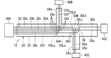
- FIG. 1 is a schematic plan view showing a wiring member according to the embodiment.
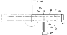
- FIG. 2 is a schematic plan view showing a state in which the above wiring member is folded.
- FIG. 3 is a schematic plan view showing a wiring member according to the first modification.
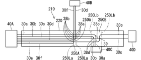
- FIG. 4 is a schematic plan view showing a wiring member according to the second modification.
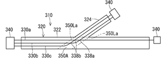
- FIG. 5 is a schematic plan view showing a wiring member according to the third modification.
- FIG. 6 is a schematic plan view showing a wiring member according to the fourth modification.
- FIG. 7 is a schematic plan view showing a wiring member according to the fifth modification.
- the wiring member of the present disclosure is as follows.
- the intersection of the plurality of linear transmission members may be located only in the branch portion. Disturbance of the path of the linear transmission member on the sheet-shaped member and separation of the linear transmission member from the sheet-shaped member are further suppressed.
- the intersection may change the arrangement order of the plurality of linear transmission members.
- a part may intersect with another linear transmission member.
- a portion where a part of the plurality of linear transmission members intersects with the other linear transmission member is defined as the branch portion.
- a part of the plurality of linear transmission members is branched on the sheet-shaped member with respect to the other linear transmission members.
- the branch portion may include an extension region from the linear transmission member that branches to the sheet member.
- a branch destination of the linear transmission member that is normally branched.
- the sheet-shaped member is bent at a position avoiding the branch destination portion of the branched linear transmission member. Therefore, if the branch portion includes an extension region from the branched linear transmission member to the sheet-shaped member, when the sheet-shaped member is bent, the sheet-shaped member is formed at the intersection of the plurality of linear transmission members. It is possible to suppress bending.
- a plurality of linear transmission members that are a part of the plurality of linear transmission members are arranged on the sheet-shaped member and the other linear transmission members.
- the sheet-shaped member may be branched and connected to a connector provided on a side edge of the sheet-shaped member, and the branched portion may include a region of the sheet-shaped member corresponding to the connector.
- a plurality of linear transmission members that are a part of the plurality of linear transmission members branch on the sheet-shaped member with respect to the other linear transmission members, and are provided at side edges of the sheet-shaped member.
- the wiring member is normally bent at a position avoiding the connector. Therefore, if the branch portion includes a region of the sheet-shaped member corresponding to the connector, the sheet-shaped member is bent at the intersection of the plurality of linear transmission members when the sheet-shaped member is bent. Can be suppressed.
- the wiring member of any one of (1) to (7) may further include a cover that covers the branched portion. At the intersections located at the branching portions, the cover further suppresses disturbance of the path of the linear transmission member on the sheet-shaped member and separation of the linear transmission member from the sheet-shaped member.
- the wiring member is located at the branching portion where it intersects with the linear transmission member.
- On the sheet-shaped member at a position where a part of the plurality of linear transmission members intersects with another linear transmission member so as to change the arrangement order of the plurality of linear transmission members. Therefore, the path of the linear transmission member is disturbed and the linear transmission member is prevented from being separated from the sheet-shaped member.
- FIG. 1 is a schematic plan view showing the wiring member 10
- FIG. 2 is a schematic plan view showing a state in which the wiring member 10 is folded.
- the linear transmission member 30 is a linear member that transmits electricity or light.
- the sheet-shaped member 20 is a sheet-shaped member.
- a plurality of linear transmission members 30 are fixed on the sheet-shaped member 20.
- a part of the plurality of linear transmission members 30 is fixed on the sheet-shaped member 20 so as to branch to the other linear transmission members 30 at the branch portions 50A and 50B.
- the branched portions 50A and 50B are areas where the linear transmission member 30 is grasped as being branched when viewed as the wiring member 10 as a whole.
- the plurality of linear transmission members 30 intersect each other on the sheet member 20, and the intersections 38a, 38b, 38c, 38d are located only at the branch portions 50A, 50B.
- the wiring member 10 With the wiring member 10 mounted on the vehicle, a plurality of connectors 40A, 40B, 40C, 40D are connected to the components mounted on the vehicle. As a result, electric signals are transmitted/received, electric power is transmitted/received, and optical signals are transmitted/received between the parts mounted on the vehicle. That is, the wiring member 10 is a wiring component that connects components mounted on the vehicle. In particular, in the wiring member 10, since the plurality of linear transmission members 30 are branched, it is possible to connect the plurality of components via the branched paths.
- the linear transmission member 30 may be a linear member that transmits electricity or light.
- the linear transmission member may be a general electric wire having a core wire and a coating around the core wire, or may be a bare conductor wire, a shield wire, an enamel wire, a nichrome wire, an optical fiber, or the like.
- the linear transmission member for transmitting electricity various signal lines and various power lines may be used.
- the linear transmission member that transmits electricity may be used as an antenna, a coil, or the like that sends or receives a signal or power to or from a space.
- the sheet-shaped member 20 is a flexible sheet-shaped member that can hold the electric wire 30 in a two-dimensionally positioned state and can be bent.
- the material forming the sheet-shaped member 20 is not particularly limited, but the sheet-shaped member 20 is preferably made of a material containing a resin such as PVC (polyvinyl chloride), PET (polyethylene terephthalate), and PP (polypropylene). It is formed.
- the sheet-shaped member 20 may be a sheet member whose inside is uniformly filled, or may be a non-woven sheet or the like.
- the sheet-shaped member 20 may include a material such as a metal.
- the sheet-shaped member 20 may be a single layer or a plurality of laminated layers. When a plurality of layers are laminated, for example, a resin layer and a resin layer may be laminated. Further, for example, it is conceivable that the resin layer and the metal layer are laminated.
- An electric wire 30 is fixed on one main surface of the sheet-shaped member 20. On one main surface of the sheet-shaped member 20, the electric wire 30 is fixed along a fixed path.
- a plurality of electric wires 30 are fixed on one main surface of the sheet-shaped member 20.
- the path of the electric wire 30 on the sheet-shaped member 20 may be a straight line or may be a path that bends in the middle.
- the plurality of electric wires 30 are branched in the middle.
- the sheet-shaped member 20 includes a first sheet-shaped portion 22 and second sheet-shaped portions 24a and 24b.
- the second sheet-shaped portions 24 a and 24 b are bent at the intermediate portion in the extending direction of the first sheet-shaped portion 22 and branched to the side of the first sheet-shaped portion 22.
- the first sheet-shaped portion 22 is formed in a strip shape that is elongated and extends straight.
- the first sheet-shaped portion may be curved.
- the second sheet-shaped portions 24a, 24b are formed in a strip shape that is elongated and extends straight.
- the second sheet-shaped portion 24 a is branched so as to extend outward from one side portion of the first sheet-shaped portion 22 toward one side of the first sheet-shaped portion 22.
- the second sheet-shaped portion 24b is branched so as to extend outward from the other side portion of the first sheet-shaped portion 22 toward the other side of the first sheet-shaped portion 22.
- the second sheet-shaped portions 24a and 24b are provided at different positions in the extending direction of the first sheet-shaped portion 22. More specifically, the second sheet-shaped portion 24a is provided at a position near one end of the first sheet-shaped portion 22, and the second sheet-shaped portion 24b is provided at a position near the other end of the first sheet-shaped portion 22. ing.
- two of the second sheet-shaped portions may be provided at the same position in the extending direction of the first sheet-shaped portion.
- the plurality of electric wires 30 may be distinguished from the electric wires 30a, 30b, 30c, 30d, 30e, 30f.
- the plurality of electric wires 30a, 30b, 30c, 30d, 30e, 30f are fixed to the first sheet-shaped portion 22 in parallel at one end side of the first sheet-shaped portion 22.
- the plurality of electric wires 30a, 30b, 30c, 30d, 30e, 30f are connected to the connector 40A at one end of the first sheet-shaped portion 22.
- the connector 40A has a configuration in which terminals are housed in a housing in a predetermined arrangement order.
- the arrangement of the plurality of electric wires 30a, 30b, 30c, 30d, 30e, 30f is determined according to how the terminals connected to the plurality of electric wires 30a, 30b, 30c, 30d, 30e, 30f are housed in the housing. ..
- the connector 40A may be fixed to the sheet-shaped member 20.
- the ends of the electric wires 30a, 30b, 30c, 30d, 30e, 30f may extend from the sheet-shaped member 20 and be connected to the connector 40A.
- the bend radius of the electric wires 30d and 30f may be larger than the distance between the electric wires 30a, 30b, 30c, 30d, 30e, and 30f. In that case, the electric wires 30d and 30f intersect the electric wires 30a, 30b, and 30c at positions deviated from their linear extensions. Since the electric wires 30d and 30f are orthogonal to the electric wires 30a, 30b, and 30c, the distribution range of the intersection portion 38a can be narrowed in the extending direction of the first sheet-shaped portion 22. By similarly configuring the other intersections to intersect at right angles, the distribution range of the intersections can be narrowed.
- intersection of the electric wire 30d and the other electric wires 30a, 30b, 30c is the intersection 38a.
- the intersection of the electric wire 30f with the other electric wires 30a, 30b, 30c, 30e, 30f is an intersection 38b.
- the intersections 38a and 38b are an example of locations where a part of the plurality of linear transmission members intersects with another linear transmission member so as to branch.
- the electric wires 30d and 30f branch on the first sheet-shaped portion 22 with respect to the other electric wires 30a, 30b, 30c, and 30e, and extend toward the second sheet-shaped portion 24a to extend above the second sheet-shaped portion 24a. Fixed in parallel with.
- the electric wires 30d and 30f are connected to the connector 40B at the ends of the second sheet-shaped portion 24a.
- the arrangement order of the electric wires 30d and 30f is also determined according to the arrangement in which the terminals connected to the ends of the electric wires 30d and 30f are housed in the connector 40B.
- intersection of the electric wire 30a with the other electric wires 30c and 30e is the intersection 38c.
- a portion where the electric wire 30b intersects with the other electric wires 30c and 30e is an intersection portion 38d.
- the intersections 38c and 38d are an example of locations where some of the plurality of linear transmission members intersect so as to branch to other linear transmission members.
- the remaining electric wires 30c and 30e extend toward the other end of the first sheet-shaped portion 22.
- the arrangement order of the electric wires 30c and 30e at the other end of the first sheet-shaped portion 22 is determined according to the arrangement in which the terminals connected to the ends of the electric wires 30a and 30b are accommodated in the connector 40D.
- the arrangement order of the electric wires 30c and 30e at the other end of the first sheet-shaped portion 22 and the electric wires 30c and 30e at the one end of the first sheet-shaped portion 22 are arranged.
- the order of arrangement is different.
- the electric wire 30e is bent midway so as to intersect the electric wire 30c so as to change the arrangement order of the plurality of electric wires 30c and 30e.
- the electric wire 30e is bent so as to cross the electric wire 30c near the intersections 38c and 38d, and extends in parallel with the electric wire 30c at a position near the other end of the first sheet-shaped portion 22.
- the electric wire 30e intersects the electric wire 30c in an orthogonal posture, and portions of the electric wire 30e on both sides intersecting the electric wire 30c extend in a parallel posture with respect to the electric wire 30c.
- a portion of the electric wire 30e that intersects the electric wire 30c and a portion that extends parallel to the electric wire 30c are curved in a curved line.
- This bending radius may be similar to the distance between the electric wires 30a, 30b, 30c, 30d, 30e, and 30f, may be smaller than the distance, or may be larger than the distance, as described above. Good.
- a crossing point 39 between the electric wire 30c and the electric wire 30e is an example of a crossing point between the electric wire 30c and the electric wire 30e so that the arrangement order of the electric wires 30c and 30e is changed.
- the electric wires 30c and 30e are fixed in parallel on the other end of the first sheet-shaped portion 22.
- the electric wires 30c and 30e are connected to the connector 40D at the other end of the first sheet-shaped portion 22.
- intersections 38a, 38b, 38c, 38d, 39 are located only at the branch points.
- the branching portion of the wiring member is a portion where some of the plurality of electric wires branch from other electric wires.
- the reason why the intersections 38a, 38b, 38c, 38d, 39 are located only at the branching portions is that the intersections 38a, This is for avoiding bending of 38b, 38c, 38d and 39. That is, when the plurality of electric wires 30 are fixed to the sheet-shaped member 20, when the plurality of electric wires 30 cross each other, the holding strength of the electric wires 30 located on the upper side apart from the sheet-shaped member 20 is increased. May be weak.
- the branch portions 50A and 50B may be regarded as an extension region from the second sheet-shaped portions 24a and 24b to the first sheet-shaped portion 22. If the first sheet-shaped portion 22 is bent in the area where the second sheet-shaped portions 24a and 24b are present, it is necessary to bend the second sheet-shaped portions 24a and 24b, and the bending work is troublesome. Also, the bent form is not stable. Therefore, even if the wiring member 10 is bent, it is usually avoided that the wiring member 10 is bent in the region where the second sheet-shaped portions 24a and 24b are present.
- the second sheet-shaped portion 24a is branched from one side of the first sheet-shaped portion 22.
- a quadrangle region surrounded by a pair of lines 50La extending from both side edges of the second sheet-shaped portion 24a to the first sheet-shaped portion 22 and both side edges of the first sheet-shaped portion 22 may be regarded as a branched portion 50A. ..
- the second sheet-shaped portion 24b is branched from the other side of the first sheet-shaped portion 22.
- a quadrangle region surrounded by a pair of lines 50Lb extending from both side edges of the second sheet-shaped portion 24b to the first sheet-shaped portion 22 and both side edges of the first sheet-shaped portion 22 may be regarded as a branched portion 50B. ..
- the intersections 38a, 38b are located in the branch portion 50A, and the intersections 38c, 38d, 39 are located in the branch portion 50B.
- the electric wire 30 and the sheet-shaped member 20 are sandwiched, and the electric wire 30 and the sheet-shaped member 20 are maintained in a fixed state.
- the electric wire 30 and the sheet-shaped member 20 are in a state of being fixed at the contact portion.
- the respective descriptions regarding the fixing of the contact portion can be applied to the fixing of the non-contact portion as long as the configuration is not applicable.
- the contact portion may be indirectly fixed, the contact portion may be directly fixed, or both may be used together in different areas.
- the contact portion indirect fixing means that the electric wire 30 and the sheet-shaped member 20 are indirectly fixed to each other through an intervening member such as an adhesive, a pressure-sensitive adhesive, or a double-sided pressure-sensitive adhesive tape provided therebetween.
- the direct fixing of the contact portion means that the electric wire 30 and the sheet-shaped member 20 are directly fixed to each other without an adhesive or the like provided separately.
- the direct fixing of the contact portion it is conceivable that the resin contained in at least one of the electric wire 30 and the sheet-shaped member 20 is melted and fixed to the contact portion. Below, it demonstrates as what the electric wire 30 and the sheet-shaped member 20 are in the state of a contact site direct fixation. The respective descriptions regarding the direct fixing of the contact portion can be applied to the indirect fixing of the contact portion as long as the configuration is not applicable.
- the resin When the state of directly fixing the contact portion is formed, the resin may be melted by heat or may be melted by a solvent, for example. That is, the state of directly fixing the contact portion may be a state of directly fixing the contact portion by heat or a state of directly fixing the contact portion by a solvent. It is preferable that the contact portion is directly fixed by heat.
- the structure for directly fixing the contact portion is not particularly limited, and various structures including known structures such as welding, fusion, and welding can be used.
- various welding configurations such as ultrasonic welding, heating/pressurizing welding, hot air welding, and high frequency welding can be adopted.
- the contact portion directly fixed state is formed by these configurations, the electric wire 30 and the sheet-shaped member 20 are brought into the contact portion directly fixed state by the configuration.
- the state where the contact portion is directly fixed is formed by ultrasonic welding
- the electric wire 30 and the sheet-shaped member 20 are brought into the state where the contact portion is directly fixed by ultrasonic welding.
- both the resin contained in the coating of the electric wire 30 and the resin contained in the sheet-shaped member 20 may be melted. In this case, both resins may be mixed and a clear interface may not be formed.
- both resins may be mixed with each other and a clear interface may not be formed.
- the wiring member 10 configured in this way is bent at a position avoiding the branch parts 50A and 50B.
- the first sheet-shaped portion 22 is bent at a position closer to one end side with respect to the branched portion 50A.
- the bending may be performed so that the wiring members 10 can be stacked.
- the wiring member 10 is usually bent at a position avoiding the branch portions 50A and 50B, and then packed, transported, and the like. Therefore, by arranging the intersections 38a, 38b, 38c, 38d, 39 of the electric wire 30 to be located only in the branch portions 50A, 50B, the wiring member 10 with the electric wire 30 fixed to the sheet-like member 20 is bent. At this time, the path of the electric wire 30 is disturbed on the sheet-shaped member 20 and the electric wire 30 is prevented from being separated from the sheet-shaped member 20.
- intersection point 39 where a part of the plurality of electric wires 30 intersects the other electric wire 30 is branched so that the arrangement order of the plurality of electric wires 30 (here, the electric wires 30c and 30e) is changed.
- the wiring member 10 By positioning the wiring member 10 in the portion 50B, it is possible to prevent the route of the electric wire 30 from being disturbed on the sheet-shaped member 20 and the electric wire 30 from being separated from the sheet-shaped member 20 when the wiring member 10 is bent.
- this configuration is adopted, even if the other crossing points 38a, 38b, 38c, 38d are located other than the branch portions 50A, 50B, the sheet-shaped member is used for the crossing point for changing the arrangement order.
- the present specification is a wiring member including a sheet-shaped member and a plurality of linear transmission members fixed on the sheet-shaped member, wherein a part of the plurality of linear transmission members is provided.
- the plurality of linear transmission members are fixed on the sheet-shaped member so as to be branched at a branching portion with respect to the other linear transmission members, and to change the arrangement order of the plurality of linear transmission members. It discloses that a part of which intersects with the other linear transmission member is located at a branch portion.
- the first sheet-shaped portion 22 is usually formed into the second sheet in order to reduce the number of bent portions of the sheet-shaped member 20. It is bent at a position avoiding the shaped portions 24a and 24b. Therefore, assuming that the branch portions 50A and 50B are extension regions from the second sheet-shaped portions 24a and 24b to the first sheet-shaped portion 22, when the wiring member 10 is bent, the electric wire 30 is placed on the sheet-shaped member 20. Is prevented from being disturbed or the electric wire 30 is separated from the sheet-shaped member 20.
- FIG. 3 is a schematic plan view showing the wiring member 110 according to the first modification.
- the wiring member 110 further includes a cover 160 that covers the branched portions 50A and 50B.
- the cover 160 that covers the branched portion 50A is larger than the branched portion 50A, and thus covers the entire branched portion 50A.
- the cover 160 that covers the branched portion 50B is larger than the branched portion 50B, and thus covers the entire branched portion 50B.
- the cover 160 does not need to cover the entire branched portions 50A and 50B, but may cover at least the intersections 38a, 38b, 38c, 38d and 39.
- the cover 160 may be a resin sheet of PVC, PE, PET, PP, PA or the like, or a metal sheet of aluminum or copper, for example.
- the cover 160 may be a fibrous material such as a woven fabric, a knitted fabric, or a non-woven fabric, or a molded material such as a member formed by extrusion molding or injection molding.
- the cover 160 may be a foam material that is foam-molded, or may be a solid material that is not foam-molded and is substantially solid. Further, the cover 160 may have only one layer or may have a plurality of layers.
- the cover 160 may be fixed to the sheet member 20 by any configuration.
- the cover 160 may be fixed to the sheet-shaped member 20 in a lateral region of the main surface of the sheet-shaped member 20 that avoids the path of the electric wire 30. Further, the cover 160 may be fixed to the sheet-shaped member 20 in the entire main surface area of the sheet-shaped member 20.
- the fixing mode of both the same structure as that of fixing the electric wire 30 to the sheet-shaped member 20 can be adopted. That is, the fixing mode of both may be fixed at the contact site, fixed at the non-contact site, or both may be used together. Further, as a mode of fixing the contact portion, the contact portion may be indirectly fixed, the contact portion may be directly fixed, or both may be used together in different areas.
- the cover 160 can be fixed to the sheet-like member 20 by ultrasonic welding, heating/pressurizing welding, hot air welding, high-frequency welding, or the like.
- the cover 160 may be provided only on a part thereof.
- FIG. 4 is a schematic plan view showing a wiring member 210 according to the second modification.
- the sheet-shaped member 220 corresponding to the sheet-shaped member 20 does not have the second sheet-shaped portions 24a and 24b. That is, the sheet-like member 220 is formed in a shape that extends so as to draw one line without branching as a whole, in this case, a strip shape that is elongated and extends straight.
- the plurality of electric wires 30a, 30b, 30c, 30d, 30e, 30f are fixed on the sheet-shaped member 220 along the same route as in the above embodiment.
- some of the electric wires 30d and 30f are branched from the other electric wires 30a, 30b, 30c, and 30e at the intermediate portion in the extending direction of the sheet-shaped member 220. Some of the electric wires 30d and 30f are branched and extend in a posture orthogonal to the other electric wires 30a, 30b, 30c and 30e.
- the branch portion 250A may be regarded as an extension region from the branched electric wires 30d and 30f to the sheet-shaped member 220. That is, when the plurality of electric wires 30d and 30f are branched, the electric wires 30d and 30f on both sides in the parallel direction are surrounded by a pair of wires 250La extending toward the sheet-like member 220 and both side edges of the sheet-like member 220.
- the area may be regarded as the branched portion 250A.
- the sheet-shaped member 220 When the wiring member 210 is folded into a compact form when it is packed, transported, or the like, the sheet-shaped member 220 is usually used to suppress the bending of the branch destination portions of the branched electric wires 30d and 30f. It is bent at a position avoiding the branch points of 30d and 30f. For this reason, when the sheet-shaped member 220 is bent, the sheet-shaped member 220 includes the intersections 38a of the plurality of electric wires 30 when the sheet-shaped member 220 is bent, including the extension regions from the electric wires 30d and 30f where the branch portion 250A branches to the sheet-shaped member 220. The bending at 38b can be suppressed. Thereby, when the wiring member 10 is bent, it is possible to prevent the path of the electric wire 30 from being disturbed on the sheet-shaped member 20 and the electric wire 30 from being separated from the sheet-shaped member 20.
- the intersection of the branching electric wire and another electric wire should be on the extension of the branching electric wire.
- the range surrounded by the linear extensions of the two branching electric wires on both sides in the parallel direction is a branching portion, and the intersecting point exists within the range. In such a branch portion, there may be a crossing point for changing the arrangement order of the electric wires.
- some of the electric wires 30a and 30b are different from the other electric wires 30c at a position that is an intermediate portion in the extending direction of the sheet-shaped member 220 and is displaced to the other end side of the sheet-shaped member 220 with respect to the electric wires 30d and 30f. , 30e.
- Some of the electric wires 30a and 30b are branched and extend in a posture orthogonal to the other electric wires 30c and 30e.
- the electric wires 30a and 30b are branched by the sheet-like member 220 with respect to the other electric wires 30c and 30e, extend toward the other side of the sheet-like member 220, and are fixed in parallel on the sheet-like member 220.
- a connector 40C is provided at the other edge of the sheet member 220.
- the connector 40C may be fixed to the edge portion of the sheet-shaped member 220 or may not be fixed.
- the connector 40C may be arranged so as to overlap the edge of the sheet-shaped member 220, or may be separated from the edge of the sheet-shaped member 220.
- the connector 40C may be arranged along the edge of the sheet-shaped member 220 as close as possible to the bending of the sheet-shaped member 220.
- the electric wires 30a and 30b are connected to such a connector 40C.
- the branch portion 250B is an area of the sheet-shaped member 220 corresponding to the connector 40C. That is, since the connector 40C is arranged along the other edge of the sheet-shaped member 220, the pair of lines 250Lb extending from both side edges of the connector 40C toward the sheet-shaped member 220 and the sheet-shaped member 220. A rectangular area surrounded by the both side edges of may be regarded as the branched portion 250B.
- some of the electric wires 30a and 30b of the plurality of electric wires 30 branch on the sheet-shaped member 20 with respect to the other electric wires 30c and 30e, and are connected to the connector 40C provided on the side edge of the sheet-shaped member 320. If so, the wiring member 210 is normally bent at a position avoiding the connector 40C. Therefore, if the branch portion 250B includes the region of the sheet-shaped member 220 corresponding to the connector 40C, the sheet-shaped member 220 will be bent at the intersections 38c and 38d of the plurality of electric wires 30 when the sheet-shaped member 220 is bent. It is possible to suppress bending.
- the crossing point 39 where a part of the plurality of electric wires 30 intersects the other electric wires 30 is changed so that the arrangement order of the plurality of electric wires 30 (here, the electric wires 30c and 30e) is changed.
- the branch portion 250B it is possible to prevent the electric wire 30 from being disturbed on the sheet-shaped member 20 and the electric wire 30 from being separated from the sheet-shaped member 20 even at such a crossing point 39.
- some of the electric wires 330a, 330b, 330c are branched from the other electric wire 330a.
- Some of the electric wires 330b and 330c intersect the other electric wire 330a at intersections 338a and 338b, branch off, extend on the second sheet-shaped portion 324, and are fixed to the second sheet-shaped portion 324. ..
- the intersections 338a and 338b are located at the intersections of the linear extension lines of the electric wires 330b and 330c and the linear extension line of the electric wire 330a.
- the electric wires 330a, 330b, 330c are appropriately connected to the connector 340.
- a part of a plurality of electric wires may intersect with another electric wire so as to change the arrangement order of the plurality of electric wires.
- FIG. 6 is a schematic plan view showing a wiring member 410 according to the fourth modification.
- the sheet-shaped member 420 includes an elongated first sheet-shaped portion 422 and a plurality of (here, two) second sheet-shaped portions 424a and 424b branched from the first sheet-shaped portion 422.
- the second sheet-shaped portions 424 a and 424 b extend obliquely from the end of the first sheet-shaped portion 422 with respect to the first sheet-shaped portion 422.
- a plurality of electric wires 430a, 430b, 430c are fixed in parallel to the first sheet-shaped portion 422.
- the plurality of electric wires 430a, 430b, 430c are branched into two at the end of the first sheet-shaped portion 422. That is, the electric wire 430b is bent in the middle with respect to the original portion and branched to the other electric wires 430a and 430c.
- the electric wire 430b is fixed on the second sheet-shaped portion 424a.
- the electric wires 430a and 430c are bent in the middle with respect to the original part and branched to the other electric wires 430b.
- the electric wires 430a and 430c are fixed in parallel on the second sheet-shaped portion 424b. Therefore, the electric wire 430a intersects the electric wire 430b, and this intersection is referred to as an intersection 438.
- the branch portion 450A has a line 450La in which an edge of the side edges of the second sheet-shaped portion 424a farther from the second sheet-shaped portion 424b extends to the first sheet-shaped portion 422, and the second sheet-shaped portion 424b.
- the edge farther from the second sheet-shaped portion 424a may be regarded as a region surrounded by the pair of lines 450Lb extending to the first sheet-shaped portion 422 side.
- the intersection 438 is located at the branch portion 450A.
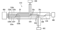
- the electric wires 530a, 530b, 530c, 530d, 530e, 530f are the same as the plurality of electric wires 30a, 30b, 30c, 30d, 30e, 30f in the embodiment.
- the connectors 40A, 40B, 40C and 40D are connected.
- This wiring member 510 is different from the wiring member 10 in the embodiment in that the electric wire 530f intersects with other electric wires 530b, 530c, 530d, 530e, 530f at a location 539b and the electric wire 530e is different from the other electric wire 530c. The intersection 539.
- Part of the electric wire 530f is bent between the end of the sheet-shaped member 20 and the branch portion 50A, and intersects with the other electric wires 530a, 530b, 530c, 530d, and 530e at an intersection 539b.
- the electric wire 530f is arranged in parallel with the electric wires 530a, 530b, 530c, 530d, and 530e before and after the intersection 539b.
- the arrangement order of the electric wires 530f for the electric wires 530a, 530b, 530c, 530d, and 530e is different before and after the intersection 539b.
- a crossing point 38c is a position where the electric wire 530a crosses the other electric wires 530c and 530e.
- a portion where the electric wire 530b intersects with the other electric wires 530c and 530e is an intersection portion 38d.
- the intersections 38c and 38d are an example of locations where some of the plurality of linear transmission members intersect so as to branch to other linear transmission members. The intersections 38c and 38d are located at the branch portion 50B.
- the electric wires 530c and 530e extend toward the other end of the sheet-shaped member 20. Similar to the first embodiment, the arrangement order of the electric wires 530c and 530e is different between one end portion and the other end portion of the sheet-shaped member 20. Therefore, the electric wire 530e is bent in the middle and intersects the electric wire 530c so as to change the arrangement order of the plurality of electric wires 530c and 530e. Here, the electric wire 530e is bent between the other end of the sheet-shaped member 20 and the branch portion 50B and intersects the electric wire 530c at the intersection 539b. The electric wire 530e is parallel to the electric wire 530c before and after the intersection 539.
- intersection portion 539 is a portion where a part of the plurality of linear transmission members intersects with the other linear transmission members so that the arrangement order of the plurality of linear transmission members is changed. Is.
- the intersection 539 is located on the sheet-shaped member 20 at a position avoiding the branched portions 50A and 50B.
- intersections 38a, 38c, 38d of the plurality of intersections of the plurality of linear transmission members are located in the branch portions 50A, 50B, and some other intersections 539b, Even when 539 is present at a position avoiding the branched portions 50A, 50B, when the wiring member 510 is bent, the electric wires 530a, 530b, 530c, 530d, 530e, 530f on the sheet member 20 are bent. Disturbance of the path and separation of the electric wires 530a, 530b, 530c, 530d, 530e, and 530f from the sheet-shaped member 20 are suppressed.
- intersections 38a, 38c, 38d and the intersections 539b, 539 are dispersed in a wider area, it becomes difficult to concentrate the intersections of the electric wires in a narrow area. This makes it difficult for the electric wires 530a, 530b, 530c, 530d, 530e, and 530f to separate from the sheet-like member 20, and to prevent the electric wires 530a, 530b, 530c, 530d, 530e, and 530f from being caught or fluttering.
Landscapes
- Engineering & Computer Science (AREA)
- Architecture (AREA)
- Civil Engineering (AREA)
- Structural Engineering (AREA)
- Mechanical Engineering (AREA)
- Details Of Indoor Wiring (AREA)
- Insulated Conductors (AREA)
- Installation Of Indoor Wiring (AREA)
Abstract
シート状部材上に線状伝送部材を固定した配線部材を折曲げる際に、シート状部材上で線状伝送部材の経路が乱れたり、シート状部材から線状伝送部材が分離したりすることを抑制することを目的とする。配線部材は、シート状部材と、前記シート状部材上に固定された複数の線状伝送部材と、を備える。前記複数の線状伝送部材のうちの一部が他の前記線状伝送部材に対して分岐部分で分岐するように前記シート状部材上に固定されている。前記複数の線状伝送部材の交差箇所が前記分岐部分に位置している。
Description
この発明は、配線部材に関する。
特許文献1は、シート状に形成された機能性外装部材と、長手方向に沿った少なくとも一部の領域で前記機能性外装部材に重なるように配設された電線と、を備え、前記電線の絶縁被覆と前記機能性外装部材とが重なる部分の少なくとも一部が溶着されている、ワイヤーハーネスを開示している。
特許文献1に開示されたワイヤーハーネスは、梱包、搬送時等において、シート状に形成された機能性外装部材を折曲げることで、コンパクトな形態にすることができる。
しかしながら、ワイヤーハーネスを折曲げると、機能性外装部材上で電線の経路が乱れたり、剥がれたりする恐れがある。例えば、特許文献1に開示のワイヤーハーネスでは、電線の経路、コネクタへの接続先位置等に応じて、シート状の機能性外装部材上で、いずれかの電線が他の電線を跨ぐようにして交差して配設される場合があり得る。電線の交差部分では、他の電線を跨ぐ電線の保持力が弱くなる。このため、電線の交差部分で、機能性外装部材が折曲げられると、機能性外装部材上で電線の経路が乱れたり、剥がれたりする恐れがある。
そこで、本開示は、シート状部材上に線状伝送部材を固定した配線部材を折曲げる際に、シート状部材上で線状伝送部材の経路が乱れたり、シート状部材から線状伝送部材が分離したりすることを抑制することを目的とする。
本開示の配線部材は、シート状部材と、前記シート状部材上に固定された複数の線状伝送部材と、を備え、前記複数の線状伝送部材のうちの一部が他の前記線状伝送部材に対して分岐部分で分岐するように、前記複数の線状伝送部材が前記シート状部材上に固定され、前記複数の線状伝送部材の交差箇所が前記分岐部分に位置しているものである。
また、本開示の配線部材は、シート状部材と、前記シート状部材上に固定された複数の線状伝送部材と、を備え、前記複数の線状伝送部材のうちの一部が他の前記線状伝送部材に対して分岐部分で分岐するように前記シート状部材上に固定され、前記複数の線状伝送部材の並び順を変更するように、前記複数の線状伝送部材のうちの一部が他の前記線状伝送部材に対して交差している箇所が分岐部分に位置しているものである。
本開示によれば、シート状部材上に線状伝送部材を固定した配線部材を折曲げる際に、シート状部材上で線状伝送部材の経路が乱れたり、シート状部材から線状伝送部材が分離したりすることが抑制される。
[本開示の実施形態の説明]
最初に本開示の実施態様を列記して説明する。
最初に本開示の実施態様を列記して説明する。
本開示の配線部材は、次の通りである。
(1)シート状部材と、前記シート状部材上に固定された複数の線状伝送部材と、を備え、前記複数の線状伝送部材のうちの一部が他の前記線状伝送部材に対して分岐部分で分岐するように、前記複数の線状伝送部材が前記シート状部材上に固定され、前記複数の線状伝送部材の交差箇所が前記分岐部分に位置している配線部材である。
配線部材においては、通常、分岐部分を避けた位置で折曲げられて、梱包、搬送等される。そこで、第1の態様のように、複数の線状伝送部材の交差箇所が分岐部分に位置している構成とすることで、シート状部材上に線状伝送部材を固定した配線部材を折曲げる際に、シート状部材上で線状伝送部材の経路が乱れたり、シート状部材から線状伝送部材が分離したりすることが抑制される。
(2)(1)の配線部材において、前記複数の線状伝送部材の交差箇所が前記分岐部分のみに位置していてもよい。シート状部材上で線状伝送部材の経路が乱れたり、シート状部材から線状伝送部材が分離したりすることがより抑制される。
(3)(1)又は(2)の配線部材において、前記交差箇所は、前記複数の線状伝送部材のうちの一部が他の前記線状伝送部材に対して分岐するように交差している箇所を含んでもよい。前記複数の線状伝送部材のうちの一部が他の前記線状伝送部材に対して分岐するように交差している箇所を、前記分岐部分に位置させることで、シート状部材上に線状伝送部材を固定した配線部材を折曲げる際に、シート状部材上で線状伝送部材の経路が乱れたり、シート状部材から線状伝送部材が分離したりすることが抑制される。
(4)(1)から(3)のいずれか1つの配線部材において、前記交差箇所は、前記複数の線状伝送部材の並び順を変更するように、前記複数の線状伝送部材のうちの一部が他の前記線状伝送部材に対して交差している箇所を含んでもよい。前記複数の線状伝送部材の並び順を変更するように、前記複数の線状伝送部材のうちの一部が他の前記線状伝送部材に対して交差している箇所を、前記分岐部分に位置させることで、シート状部材上に線状伝送部材を固定した配線部材を折曲げる際に、シート状部材上で線状伝送部材の経路が乱れたり、シート状部材から線状伝送部材が分離したりすることが抑制される。
(5)(1)から(4)のいずれか1つの配線部材において、前記シート状部材は、第1シート状部分と、前記第1シート状部分から分岐する第2シート状部分とを含み、前記複数の線状伝送部材のうちの一部は前記第1シート状部分で他の前記線状伝送部材に対して分岐して、前記第2シート状部分上に固定され、前記分岐部分は、前記第2シート状部分から前記第1シート状部分への延長領域を含んでもよい。シート状部材が、第1シート状部分と、第1シート状部分から分岐する第2シート状部分とを含む場合、通常、シート状部材の折曲げ箇所を少なくするため、第1シート状部材は、第2シート状部分を避けた位置で折曲げられる。このため、分岐部分が、前記第2シート状部分から前記第1シート状部分への延長領域を含めば、シート状部材を折曲げる際に、シート状部材が複数の線状伝送部材の交差箇所で折曲げられることを抑制できる。
(6)(1)から(5)のいずれか1つの配線部材において、前記複数の線状伝送部材のうちの一部が前記シート状部材上で他の前記線状伝送部材に対して分岐しており、前記分岐部分は、分岐する前記線状伝送部材から前記シート状部材への延長領域を含んでもよい。前記複数の線状伝送部材のうちの一部の線状伝送部材がシート状部材上で他の前記線状伝送部材に対して分岐している場合、通常、分岐する線状伝送部材の分岐先部分の折曲げを抑制するため、シート状部材は、分岐する線状伝送部材の分岐先部分を避けた位置で折曲げられる。このため、分岐部分が、分岐する前記線状伝送部材から前記シート状部材への延長領域を含めば、シート状部材を折曲げる際に、シート状部材が複数の線状伝送部材の交差箇所で折曲げられることを抑制できる。
(7)(1)から(6)のいずれか1つの配線部材において、前記複数の線状伝送部材のうちの一部である複数の線状伝送部材が前記シート状部材上で他の前記線状伝送部材に対して分岐し、前記シート状部材の側縁に設けられたコネクタに接続されており、前記分岐部分は、前記シート状部材のうち前記コネクタに対応する領域を含んでもよい。前記複数の線状伝送部材のうちの一部である複数の線状伝送部材が前記シート状部材上で他の前記線状伝送部材に対して分岐し、前記シート状部材の側縁に設けられたコネクタに接続されている場合、通常、配線部材は、コネクタを避けた位置で折曲げられる。このため、分岐部分が、前記シート状部材のうち前記コネクタに対応する領域を含めば、シート状部材を折曲げる際に、シート状部材が複数の線状伝送部材の交差箇所で折曲げられることを抑制できる。
(8)(1)から(7)のいずれか1つの配線部材において、前記分岐部分を覆うカバーをさらに備えてもよい。分岐部分に位置する交差箇所において、カバーによって、シート状部材上で線状伝送部材の経路が乱れたり、シート状部材から線状伝送部材が分離したりすることがより抑制される。
(9)シート状部材と、前記シート状部材上に固定された複数の線状伝送部材と、を備え、前記複数の線状伝送部材のうちの一部が他の前記線状伝送部材に対して分岐部分で分岐するように前記シート状部材上に固定され、前記複数の線状伝送部材の並び順を変更するように、前記複数の線状伝送部材のうちの一部が他の前記線状伝送部材に対して交差している箇所が分岐部分に位置している配線部材である。前記複数の線状伝送部材の並び順を変更するように、前記複数の線状伝送部材のうちの一部が他の前記線状伝送部材に対して交差している箇所において、シート状部材上で線状伝送部材の経路が乱れたり、シート状部材から線状伝送部材が分離したりすることが抑制される。
[本開示の実施形態の詳細]
本開示の配線部材の具体例を、以下に図面を参照しつつ説明する。なお、本開示はこれらの例示に限定されるものではなく、請求の範囲によって示され、請求の範囲と均等の意味および範囲内でのすべての変更が含まれることが意図される。
本開示の配線部材の具体例を、以下に図面を参照しつつ説明する。なお、本開示はこれらの例示に限定されるものではなく、請求の範囲によって示され、請求の範囲と均等の意味および範囲内でのすべての変更が含まれることが意図される。
[実施形態1]
以下、実施形態に係る配線部材について説明する。図1は配線部材10を示す概略平面図であり、図2は同配線部材10を折畳んだ状態を示す概略平面図である。
以下、実施形態に係る配線部材について説明する。図1は配線部材10を示す概略平面図であり、図2は同配線部材10を折畳んだ状態を示す概略平面図である。
配線部材10は、シート状部材20と、複数の線状伝送部材30とを備える。本例では、配線部材10は、コネクタ40A、40B、40C、40Dをも備える。
線状伝送部材30は、電気又は光を伝送する線状部材である。シート状部材20は、シート状の部材である。このシート状部材20上に、複数の線状伝送部材30が固定される。複数の線状伝送部材30のうちの一部は他の線状伝送部材30に対して分岐部分50A、50Bで分岐するように、シート状部材20上に固定されている。分岐部分50A、50Bは、配線部材10全体として見た場合に、線状伝送部材30が分岐していると把握される領域である。複数の線状伝送部材30は、シート状部材20上で交差しており、この交差箇所38a、38b、38c、38dが分岐部分50A、50Bのみに位置している。
コネクタ40A、40B、40C、40Dは、車両に搭載された部品に接続される部品である。複数の線状伝送部材30の端部がコネクタ40A、40B、40C、40Dのいずれかに接続されている。コネクタ40A、40B、40C、40Dが車両に搭載された相手側のコネクタに接続されることで、線状伝送部材30と当該部品とが電気的に接続され、或は、光信号を送受可能に接続される。
本配線部材10が車両に搭載された状態で、複数のコネクタ40A、40B、40C、40Dが車両に搭載された各部品に接続される。これにより、車両に搭載された部品の間で、電気信号の送受信、電力の送受、光信号の送受信がなされる。つまり、配線部材10は、車両に搭載された部品同士を接続する配線部品である。特に、配線部材10において、複数の線状伝送部材30が分岐していることから、複数の部品を分岐した経路を介して接続することが可能となる。
各部についてより具体的に説明する。
線状伝送部材30は、電気又は光等を伝送する線状の部材であればよい。例えば、線状伝送部材は、芯線と芯線の周囲の被覆とを有する一般電線であってもよいし、裸導線、シールド線、エナメル線、ニクロム線、光ファイバ等であってもよい。
電気を伝送する線状伝送部材としては、各種信号線、各種電力線であってもよい。電気を伝送する線状伝送部材は、信号又は電力を空間に対して送る又は空間から受けるアンテナ、コイル等として用いられてもよい。
ここでは線状伝送部材30が一般電線30(以下、単に電線30という)であるものとして説明する。電線30は、伝送線本体としての芯線と、芯線を覆う被覆としての絶縁被覆とを有する。電線に関する各説明は、適用不可能な構成を除き、線状伝送部材の各例示物に適用可能である。
芯線は、1本又は複数本の素線で構成される。素線は、銅、銅合金、アルミニウム、アルミニウム合金等の導体で形成される。芯線が複数本の素線で構成される場合、複数本の素線は撚られていてもよい。絶縁被覆は、PVC(ポリ塩化ビニル)、PE(ポリエチレン)などの樹脂材料が芯線の周囲に押出成形されるなどして形成される。ここでは電線30は、横断面が円形のいわゆる丸電線である。
シート状部材20は、電線30を2次元的に位置決めした状態で保持でき、かつ、折曲げ可能な柔軟なシート状部材である。
シート状部材20を構成する材料は特に限定されるものではないが、シート状部材20は、好ましくはPVC(ポリ塩化ビニル)、PET(ポリエチレンテレフタレート)、PP(ポリプロピレン)等の樹脂を含む材料によって形成される。シート状部材20は、内部が一様に埋ったシート部材であってもよいし、不織シート等であってもよい。シート状部材20は、金属などの材料を含むこともあり得る。シート状部材20は、単層であってもよいし、複数層積層されていてもよい。複数層積層されている場合、例えば、樹脂層と樹脂層とが積層されていることが考えられる。また例えば、樹脂層と金属層とが積層されていることが考えられる。
シート状部材20の一主面上に、電線30が固定されている。シート状部材20の一主面上において、電線30は一定の経路に沿って固定されている。
シート状部材20の一主面上には、複数の電線30が固定される。シート状部材20上における電線30の経路は、直線であってもよいし、途中で曲る経路であってもよい。シート状部材20の一主面上において、複数の電線30は途中で分岐している。
より具体的には、シート状部材20は、第1シート状部分22と、第2シート状部分24a、24bとを含む。第2シート状部分24a、24bは、第1シート状部分22の延在方向中間部で曲って第1シート状部分22の側方に分岐している。ここでは、第1シート状部分22は、細長く真っ直ぐ延びる帯状に形成されている。第1シート状部分は曲っていてもよい。第2シート状部分24a、24bは細長く真っ直ぐ延びる帯状に形成されている。第2シート状部分24aは、第1シート状部分22の一側部の延在方向中間部から第1シート状部分22の一側外方に向けて延在するように分岐している。第2シート状部分24bは、第1シート状部分22の他側部の延在方向中間部から第1シート状部分22の他側外方に向けて延在するように分岐している。ここでは、第2シート状部分24a、24bは、第1シート状部分22の延在方向において異なる箇所に設けられている。より具体的には、第2シート状部分24aは第1シート状部分22の一端寄りの位置に設けられ、第2シート状部分24bは第1シート状部分22の他端寄りの位置に設けられている。第2シート状部分が複数設けられる場合、そのうちの2つの第2シート状部分が第1シート状部分の延在方向において同じ位置に設けられていてもよい。また、第2シート状部分24a、24bは、第1シート状部分22の延在方向に対して直交する姿勢で延出している。第2シート状部分は、第1シート状部分の延在方向に対して斜め方向に延出していてもよい。第2シート状部分は、1つであってもよく、3つ以上であってもよい。
便宜上、複数の電線30を、電線30a、30b、30c、30d、30e、30fと区別する場合がある。複数の電線30a、30b、30c、30d、30e、30fは、第1シート状部分22の一端側では、並列状態で第1シート状部分22に固定されている。複数の電線30a、30b、30c、30d、30e、30fは、第1シート状部分22の一端部でコネクタ40Aに接続されている。コネクタ40Aは、端子が所定の並び順で、ハウジングに収容された構成とされている。複数の電線30a、30b、30c、30d、30e、30fの並びは、複数の電線30a、30b、30c、30d、30e、30fに接続される端子がハウジングに収容される並びに応じて決定されている。コネクタ40Aは、シート状部材20に固定されていてもよい。電線30a、30b、30c、30d、30e、30fの端部がシート状部材20から延出してコネクタ40Aに接続されていてもよい。これは、他のコネクタ40B、40C、40Dについても同様である。
第1シート状部分22の延在方向中間部で、一部の電線30d、30fが途中で元の部分から曲って他の電線30a、30b、30c、30eに対して分岐している。一部の電線30d、30fは、他の電線30a、30b、30c、30eに対して分岐して直交する姿勢で延在している。電線30d、30fの曲げ半径が、電線30a、30b、30c、30d、30e、30fの間隔と同程度又は当該間隔よりも小さいと、電線30d、30fと、電線30a、30b、30cとは、それぞれの直線延長上で交差する。電線30d、30fの曲げ半径は、電線30a、30b、30c、30d、30e、30fの間隔よりも大きくてもよい。その場合、電線30d、30fは、電線30a、30b、30cに対して、それらの直線延長上からずれた位置で交差する。電線30d、30fが電線30a、30b、30cに対して直交していることから、第1シート状部分22の延在方向において交差箇所38aの分布範囲を狭めることができる。他の交差箇所についても、同様に直交交差する構成とすることで、交差箇所の分布範囲を狭めることができる。ここでは、電線30dが、他の電線30a、30b、30cに対して交差する箇所が交差箇所38aである。また、電線30fが他の電線30a、30b、30c、30e、30fに対して交差する箇所が交差箇所38bである。交差箇所38a、38bは、複数の線状伝送部材のうちの一部が他の線状伝送部材に対して分岐するように交差している箇所の一例である。
電線30d、30fは、第1シート状部分22上で他の電線30a、30b、30c、30eに対して分岐し、第2シート状部分24aに向けて延出して当該第2シート状部分24a上に並列状態で固定される。電線30d、30fは、第2シート状部分24aの端部で、コネクタ40Bに接続される。電線30d、30fの並び順も、電線30d、30fの端部に接続される端子がコネクタ40B内に収容される配置に応じて決定される。
第1シート状部分22の延在方向中間部であって、上記電線30d、30fよりも第1シート状部分22の他端側にずれた位置で、一部の電線30a、30bが途中で元の部分から曲って、他の電線30c、30eに対して分岐している。一部の電線30a、30bは、他の電線30c、30eに対して分岐して直交する姿勢で延在している。電線30a、30bの曲げ半径は、上記と同様に、電線30a、30b、30c、30d、30e、30fの間隔と同程度であってもよいし、当該間隔よりも小さくてもよいし、当該間隔より大きくてもよい。ここでは、電線30aが、他の電線30c、30eに対して交差する箇所が交差箇所38cである。また、電線30bが他の電線30c、30eに対して交差する箇所が交差箇所38dである。交差箇所38c、38dは、複数の線状伝送部材のうちの一部が他の線状伝送部材に対して分岐するように交差している箇所の一例である。
電線30a、30bは、第1シート状部分22上で他の電線30c、30eに対して分岐し、第2シート状部分24bに向けて延出して当該第2シート状部分24b上で並列状態で固定される。電線30a、30bは、第2シート状部分24bの端部で、コネクタ40Cに接続される。電線30a、30bの並び順も、電線30a、30bの端部に接続される端子がコネクタ40C内に収容される配置に応じて決定される。
残りの電線30c、30eは、第1シート状部分22の他端部に向けて延在する。第1シート状部分22の他端部における電線30c、30eの並び順は、電線30a、30bの端部に接続される端子がコネクタ40D内に収容される配置に応じて決定される。ここでは、コネクタ40A、40Dにおける端子の収容位置に応じて、第1シート状部分22の他端部における電線30c、30eの並び順と第1シート状部分22の一端部における電線30c、30eの並び順とが変っている。そこで、複数の電線30c、30eの並び順を変更するように、電線30eが途中で曲って電線30cに対して交差している。ここでは、交差箇所38c、38dの近くで、電線30eが電線30cに対して交差するように曲げられ、第1シート状部分22の他端部寄りの位置で、電線30cに対して平行に延在している。ここでは、電線30eは、電線30cに対して直交姿勢で交差しており、電線30eのうち電線30cと交差する両側の部分は、電線30cに対して平行姿勢で延在している。電線30eのうち電線30cと交差する部分と、電線30cに対して平行に延在する部分との間は、曲線的に曲げられている。この曲げ半径は、上記と同様に、電線30a、30b、30c、30d、30e、30fの間隔と同程度であってもよいし、当該間隔よりも小さくてもよいし、当該間隔より大きくてもよい。電線30cと電線30eとの交差箇所39が、電線30c、30eの並び順を変更するように、電線30cと電線30eとが交差する箇所の一例である。電線30c、30eは、第1シート状部分22の他端部上で並列状態で固定される。電線30c、30eは、第1シート状部分22の他端部で、コネクタ40Dに接続される。
上記交差箇所38a、38b、38c、38d、39は、分岐部分のみに位置している。配線部材における分岐部分は、複数の電線のうちの一部が他の電線から分岐する部分である。ここで、交差箇所38a、38b、38c、38d、39を、分岐部分のみに位置させる理由は、配線部材10を梱包、搬送時等において折曲げてコンパクトな形態とする際に、交差箇所38a、38b、38c、38d、39が折曲げられるのを避けるためである。すなわち、複数の電線30はシート状部材20に固定されているところ、複数の電線30が交差していると、シート状部材20から離れて上側に位置している電線30については、保持強度が弱くなる恐れがある。このため、配線部材10が交差箇所38a、38b、38c、38d、39で折曲げられると、シート状部材20上で電線30の経路が乱れたり、電線30がシート状部材20から剥がれたりする恐れがある。そこで、交差箇所38a、38b、38c、38d、39を、分岐部分のみに位置させることで、梱包、搬送時等において、配線部材10が交差箇所38a、38b、38c、38d、39で折曲げられるのを避けるようにしている。
この点からして、一例として、分岐部分50A、50Bは、第2シート状部分24a、24bから第1シート状部分22への延長領域であると捉えてもよい。仮に、第1シート状部分22を、第2シート状部分24a、24bの存在領域で折曲げると、当該第2シート状部分24a、24bを折曲げる必要が生じ、折曲げ作業が面倒であるし、また、折曲げ形態も安定しない。このため、配線部材10を折曲げるとしても、通常、第2シート状部分24a、24bの存在領域で折曲げることは、避けられるからである。
ここでは、第1シート状部分22の一側から第2シート状部分24aが分岐している。第2シート状部分24aの両側縁を第1シート状部分22に延長した一対の線50Laと、第1シート状部分22の両側縁とで囲まれる四角形の領域を分岐部分50Aと捉えてもよい。また、第1シート状部分22の他側から第2シート状部分24bが分岐している。第2シート状部分24bの両側縁を第1シート状部分22に延長した一対の線50Lbと、第1シート状部分22の両側縁とで囲まれる四角形の領域を分岐部分50Bと捉えてもよい。交差箇所38a、38bは、分岐部分50A内に位置しており、交差箇所38c、38d、39は、分岐部分50B内に位置している。
なお、電線30とシート状部材20との固定する態様は、接触部位固定であってもよいし、非接触部位固定であってもよいし、両者が併用されていてもよい。ここで接触部位固定とは、電線30とシート状部材20とが接触する部分がくっついて固定されているものである。また、非接触部位固定とは、接触部位固定でない固定態様である。例えば、縫糸、別のシート部材、粘着テープなどが、電線30をシート状部材20に向けて押え込んだり、縫糸、別のシート部材、粘着テープなどが、電線30とシート状部材20とを囲む状態等となって、電線30とシート状部材20とを挟み込んだりして、電線30とシート状部材20とが固定された状態に維持するものである。本例では、電線30とシート状部材20とが、接触部位固定の状態にあるものとして想定している。接触部位固定に関する各説明は、適用不可能な構成でない限り、非接触部位固定にも適用可能である。
係る接触部位固定の態様として、接触部位間接固定であってもよいし、接触部位直接固定であってもよいし、異なる領域で両者が併用されていてもよい。ここで接触部位間接固定とは、電線30とシート状部材20とが、その間に設けられた接着剤、粘着剤、両面粘着テープなどの介在部材を介して間接的にくっついて固定されているものである。また接触部位直接固定とは、電線30とシート状部材20とが別に設けられた接着剤等を介さずに直接くっついて固定されているものである。接触部位直接固定では、例えば電線30とシート状部材20とのうち少なくとも一方に含まれる樹脂が溶かされることによってくっついて固定されることが考えられる。以下では、電線30とシート状部材20とが、接触部位直接固定の状態にあるものとして説明する。接触部位直接固定に関する各説明は、適用不可能な構成でない限り、接触部位間接固定にも適用可能である。
係る接触部位直接固定の状態が形成されるに当たり、樹脂は、例えば、熱によって溶かされることも考えられるし、溶剤によって溶かされることも考えられる。つまり、接触部位直接固定の状態としては、熱による接触部位直接固定の状態であってもよいし、溶剤による接触部位直接固定の状態であってもよい。好ましくは、熱による接触部位直接固定の状態であるとよい。
このとき接触部位直接固定の状態を形成する構成は特に限定されるものではなく、溶着、融着、溶接等の公知の構成を含む各種構成を用いることができる。例えば、溶着によって熱による接触部位直接固定の状態を形成する場合、超音波溶着、加熱加圧溶着、熱風溶着、高周波溶着など種々の溶着構成を採用することができる。またこれらの構成によって接触部位直接固定の状態が形成されると、電線30とシート状部材20とは、その構成による接触部位直接固定の状態とされる。具体的には、例えば、超音波溶着によって接触部位直接固定の状態が形成されると、電線30とシート状部材20とは、超音波溶着による接触部位直接固定の状態とされる。溶着によって熱による接触部位直接固定の状態を形成した部分(電線30とシート状部材20との固定部分)を溶着部、このうち、超音波溶着による固定部分を超音波溶着部、加熱加圧溶着による固定部分を加熱加圧溶着部等と称してもよい。
接触部位直接固定の場合、電線30の被覆に含まれる樹脂のみが溶けていてもよいし、シート状部材20に含まれる樹脂のみが溶けていてもよい。これらの場合において、溶けた方の樹脂が他方の外面にくっついた状態となり、比較的はっきりした界面が形成されることがある。また、接触部位直接固定の場合、電線30の被覆に含まれる樹脂とシート状部材20に含まれる樹脂の両方が溶けていてもよい。この場合、両方の樹脂が混ざり合ってはっきりした界面が形成されないことがある。特に、電線30の被覆とシート状部材20とが、同じ樹脂材料など相溶しやすい樹脂を含む場合などに、両方の樹脂が混ざり合ってはっきりした界面が形成されないことがある。
このように構成された配線部材10は、分岐部分50A、50Bを避けた位置で折曲げられる。例えば、図2に示すように、第1シート状部分22のうち分岐部分50Aに対して一端側寄りの位置で折曲げられる。なお、折曲げは、配線部材10を重ねることができる程度に折曲げられればよい。
以上のように構成された配線部材10によると、配線部材10においては、通常、分岐部分50A、50Bを避けた位置で折曲げられて、梱包、搬送等される。そこで、電線30の交差箇所38a、38b、38c、38d、39が分岐部分50A、50Bのみに位置している構成とすることで、シート状部材20に電線30を固定した配線部材10を折曲げる際に、シート状部材20上で電線30の経路が乱れたり、シート状部材20から電線30が分離したりすることが抑制される。
また、複数の電線30のうちの一部が他の電線に対して分岐するように交差する交差箇所38a、38b、38c、38dを、分岐部分50A、50Bに位置させることで、配線部材10を折曲げる際に、シート状部材20上で電線30の経路が乱れたり、シート状部材20から電線30が分離したりすることが抑制される。
また、複数の電線30(ここでは電線30c、30e)の並び順を変更するように、複数の電線30のうちの一部が他の電線30に対して交差している交差箇所39を、分岐部分50Bに位置させることで、配線部材10を折曲げる際に、シート状部材20上で電線30の経路が乱れたり、シート状部材20から電線30が分離したりすることが抑制される。この構成を採用する場合、他の交差箇所38a、38b、38c、38dについては、分岐部分50A、50B以外に位置していても、当該並び順を変更するための交差箇所については、シート状部材20上で電線30の経路が乱れたり、シート状部材20から電線30が分離したりすることを抑制することができる。よって、本明細書は、シート状部材と、前記シート状部材上に固定された複数の線状伝送部材と、を備える配線部材であって、前記複数の線状伝送部材のうちの一部が他の前記線状伝送部材に対して分岐部分で分岐するように前記シート状部材上に固定され、前記複数の線状伝送部材の並び順を変更するように、前記複数の線状伝送部材のうちの一部が他の前記線状伝送部材に対して交差している箇所が分岐部分に位置しているものを開示している。
また、第1シート状部分22から第2シート状部分24a、24bが分岐している場合、通常、シート状部材20の折曲げ箇所を少なくするため、第1シート状部分22は、第2シート状部分24a、24bを避けた位置で折曲げられる。そこで、分岐部分50A、50Bが第2シート状部分24a、24bから第1シート状部分22への延長領域であるとすれば、配線部材10を折曲げる際に、シート状部材20上で電線30の経路が乱れたり、シート状部材20から電線30が分離したりすることが抑制される。
{変形例}
上記実施形態を前提として、各種変形例について説明する。
上記実施形態を前提として、各種変形例について説明する。
図3は第1変形例に係る配線部材110を示す概略平面図である。配線部材110は、分岐部分50A、50Bを覆うカバー160をさらに備える。ここでは、分岐部分50Aを覆うカバー160は、分岐部分50Aよりも大きく、従って、分岐部分50Aの全体を覆っている。また、分岐部分50Bを覆うカバー160は、分岐部分50Bよりも大きく、従って、分岐部分50Bの全体を覆っている。カバー160が分岐部分50A、50B全体を覆っている必要は無く、少なくとも交差箇所38a、38b、38c、38d、39を覆っていればよい。
カバー160としては、例えば、PVC、PE、PET、PP、PA等の樹脂シートであってもよいし、アルミニウム又は銅などの金属シートであってもよい。また、カバー160は、織物、編物、不織布等の繊維材であってもよいし、押出成形又は射出成形等による部材等の成型材であってもよい。また、カバー160は、発泡成形された発泡材であってもよいし、発泡成形されずに一様に充実な充実材であってもよい。また、カバー160は、1層のみを有するものであってもよいし、複数層を有するものであってもよい。
シート状部材20に対するカバー160の固定は、いかなる構成によってなされてもよい。例えば、シート状部材20の主面のうち電線30の経路を避けた側方領域で、カバー160がシート状部材20に固定されてもよい。また、シート状部材20の主面全体領域で、カバー160がシート状部材20に固定されていてもよい。
両者の固定態様としては、電線30をシート状部材20に固定したのと同様の構成を採用することができる。すなわち、両者の固定態様は、接触部位固定であってもよいし、非接触部位固定であってもよいし、両者が併用されていてもよい。また、接触部位固定の態様として、接触部位間接固定であってもよいし、接触部位直接固定であってもよいし、異なる領域で両者が併用されていてもよい。例えば、カバー160をシート状部材20に対して、超音波溶着、加熱加圧溶着、熱風溶着、高周波溶着等によって固定することができる。
この変形例によると、分岐部分50A、50Bに位置する交差箇所38a、38b、38c、38d、39が、カバー160によって覆われている。このため、当該カバー160によって、電線30がシート状部材20から離れに難くなり、シート状部材20上で電線30の経路が乱れたり、シート状部材20から電線30が分離したりすることが、より抑制される。また、シート状部材20に対してカバー160によって剛性が付与されるため、シート状部材20のうちカバー160が設けられた部分で曲り難くなる。このため、配線部材110が、カバー160が設けられた部分、即ち、分岐部分50A、50Bで折り曲げられ難くなり、この点からも、シート状部材20上で電線30の経路が乱れたり、シート状部材20から電線30が分離したりすることが抑制される。
本変形例において、複数の分岐部分50A、50Bが設けられる場合、その一部にのみカバー160が設けられてもよい。
図4は第2変形例に係る配線部材210を示す概略平面図である。この配線部材210において、シート状部材20に対応するシート状部材220は、第2シート状部分24a、24bを有していない。つまり、シート状部材220は、全体的に分岐しないで1つのラインを描くように延びる形状、ここでは、細長く真っ直ぐ延びる帯状に形成されている。
複数の電線30a、30b、30c、30d、30e、30fは、シート状部材220上で、上記実施形態と同様の経路に沿って固定されている。
すなわち、シート状部材220の延在方向中間部で、一部の電線30d、30fが、他の電線30a、30b、30c、30eに対して分岐している。一部の電線30d、30fは、他の電線30a、30b、30c、30eに対して分岐して直交する姿勢で延在している。
電線30d、30fは、シート状部材220上で他の電線30a、30b、30c、30eに対して分岐し、シート状部材220の一側方から外方に延出している。上記実施形態とは異なり、第2シート状部分24aが存在しないことから、電線30d、30fは、シート状部材によっては規制されない状態で外方に延出している。この部分に、粘着テープ等の外装材が外装されてもよい。
この場合、分岐部分250Aは、分岐する電線30d、30fからシート状部材220への延長領域であると捉えてもよい。すなわち、複数の電線30d、30fが分岐する場合、その並列方向両側の電線30d、30fを、シート状部材220側に延長した一対の線250Laと、シート状部材220の両側縁とで囲まれる四角形の領域を分岐部分250Aと捉えてもよい。
配線部材210を梱包、搬送時等において折曲げてコンパクトな形態とする際に、通常、分岐する電線30d、30fの分岐先部分の折曲げを抑制するため、シート状部材220は、分岐する電線30d、30fの分岐先部分を避けた位置で折曲げられる。このため、分岐部分250Aが分岐する電線30d、30fからシート状部材220への延長領域を含めば、シート状部材220を折曲げる際に、シート状部材220が複数の電線30の交差箇所38a、38bで折曲げられることを抑制できる。これにより、配線部材10を折曲げる際に、シート状部材20上で電線30の経路が乱れたり、シート状部材20から電線30が分離したりすることが抑制される。
なお、分岐する電線が1つの場合、その分岐する電線と他の電線との交差箇所が、当該分岐する電線の延長上に存在すればよい。また、分岐する電線が3つ以上の場合、分岐する複数の電線の並列方向両側のものの直線延長上に囲まれる範囲を分岐部分として、その範囲内に交差箇所が存在すればよい。このような分岐部分には、電線の並び順を変更するための交差箇所が存在してもよい。
また、シート状部材220の延在方向中間部であって、上記電線30d、30fよりもシート状部材220の他端側にずれた位置で、一部の電線30a、30bが、他の電線30c、30eに対して分岐している。一部の電線30a、30bは、他の電線30c、30eに対して分岐して直交する姿勢で延在している。
電線30a、30bは、シート状部材220で他の電線30c、30eに対して分岐し、シート状部材220の他側に向けて延びてシート状部材220上で並列状態で固定される。シート状部材220の他側の縁部にはコネクタ40Cが設けられている。コネクタ40Cは、シート状部材220の縁部に固定されていてもよいし、固定されていなくてもよい。コネクタ40Cは、シート状部材220の縁部に重なって配置されていてもよいし、シート状部材220の縁部から離れていてもよい。コネクタ40Cは、シート状部材220の折曲げの妨げになる程度の近さで、シート状部材220の縁部に沿って配置されていればよい。電線30a、30bは、このようなコネクタ40Cに接続されている。
この場合、分岐部分250Bは、シート状部材220のうちコネクタ40Cに対応する領域である。すなわち、コネクタ40Cは、シート状部材220の他方の縁部に沿って配置されていることから、コネクタ40Cの両側縁部をシート状部材220に向けて延長した一対の線250Lbとシート状部材220の両側縁とで囲まれる四角形の領域を分岐部分250Bと捉えてもよい。
このように、複数の電線30の一部の電線30a、30bがシート状部材20上で他の電線30c,30eに対して分岐し、シート状部材320の側縁に設けられたコネクタ40Cに接続されている場合、通常、配線部材210は、コネクタ40Cを避けた位置で折曲げられる。このため、分岐部分250Bが、シート状部材220のうちコネクタ40Cに対応する領域を含めば、シート状部材220を折曲げる際に、シート状部材220が複数の電線30の交差箇所38c、38dで折曲げられることを抑制できる。
また、複数の電線30(ここでは電線30c、30e)の並び順を変更するように、複数の電線30のうちの一部が他の電線30に対して交差している交差箇所39を、上記分岐部分250Bに位置させることで、そのような交差箇所39についても、シート状部材20上で電線30の経路が乱れたり、シート状部材20から電線30が分離したりすることが抑制される。
図5は第3変形例に係る配線部材310を示す概略平面図である。この配線部材310では、シート状部材320は、細長い第1シート状部分322の一側部から第2シート状部分324が分岐して延在している。第2シート状部分324は、第1シート状部分322に対して斜めに延出している。
第1シート状部分322の延在方向中間部において、複数の電線330a、330b、330cのうちの一部の電線330b、330cが他の電線330aから分岐している。一部の電線330b、330cは、他の電線330aに対して交差箇所338a、338bで交差して分岐し、第2シート状部分324上に延びて当該第2シート状部分324に固定されている。ここでは、交差箇所338a、338bは、電線330b、330cの直線延長線、及び、電線330aの直線延長線の交差箇所に位置している。第1シート状部分322の端部、及び、第2シート状部分324の端部において、電線330a、330b、330cは、適宜コネクタ340に接続されている。
この場合、分岐部分350Aは、上記実施形態と同様に、第2シート状部分324の両側縁を第1シート状部分322に延長した一対の線350Laと、第1シート状部分322の両側縁とで囲まれる四角形(ここでは平行四辺形)の領域を分岐部分350Aと捉えてもよい。上記交差箇所338a、338bは、分岐部分350Aに位置している。
分岐部分350Aには、複数の電線の並び順を変更するように、複数の電線のうちの一部が他の電線に対して交差している箇所が位置していてもよい。
かかる配線部材310においても、分岐部分350Aの近く折曲げられることは避けられると考えられるため、シート状部材320上で電線330a、330b、330cの経路が乱れたり、シート状部材320から電線330a、330b、330cが分離したりすることが抑制される。
図6は第4変形例に係る配線部材410を示す概略平面図である。この配線部材410では、シート状部材420は、細長い第1シート状部分422と、当該第1シート状部分422から分岐する複数(ここでは2つ)の第2シート状部分424a、424bを備える。第2シート状部分424a、424bは、第1シート状部分422の端部から当該第1シート状部分422に対して斜めに延出している。
複数の電線430a、430b、430cが第1シート状部分422に対して並列状態で固定されている。複数の電線430a、430b、430cは、第1シート状部分422の端部で2つに分岐している。すなわち、電線430bが途中で元の部分に対して曲って他の電線430a、430cに対して分岐している。電線430bは、第2シート状部分424a上に固定されている。電線430a、430cが途中で元の部分に対して曲って他の電線430bに対して分岐している。電線430a、430cは、第2シート状部分424b上に並列状態で固定されている。このため、電線430aは、電線430bに対して交差しており、この交差箇所を交差箇所438とする。
第1シート状部分422の端部、及び、第2シート状部分424a、424bの端部において、電線430a、430b、430cは、適宜コネクタ440に接続されている。
この場合、分岐部分450Aは、第2シート状部分424aの両側縁のうち第2シート状部分424bから遠い側の縁を第1シート状部分422に延長した線450Laと、第2シート状部分424bの両側縁のうち第2シート状部分424aから遠い側の縁を第1シート状部分422側に延長した一対の線450Lbとで囲まれる領域と捉えてもよい。上記交差箇所438は、分岐部分450Aに位置している。
かかる配線部材410においても、分岐部分450Aの近く折曲げられることは避けられると考えられるため、シート状部材420上で電線430a、430b、430cの経路が乱れたり、シート状部材420から電線430a、430b、430cが分離したりすることが抑制される。
上記実施形態及び各変形例に限られず、シート状部材と、シート状部材上に固定された複数の線状伝送部材とを備える配線部材において、複数の線状伝送部材のうちの一部が他の線状伝送部材に対して分岐部分で分岐するように、複数の線状伝送部材がシート状部材上に固定される場合において、複数の線状伝送部材の交差箇所が分岐部分に位置していればよい。複数の線状伝送部材の交差箇所が分岐部分に位置していれば、その部分では、配線部材を折曲げる際に、シート状部材上で線状伝送部材の経路が乱れたり、シート状部材から線状伝送部材が分離したりすることが抑制されるからである。
例えば、図7に示す第5変形例に係る配線部材510では、電線530a、530b、530c、530d、530e、530fは、実施形態における複数の電線30a、30b、30c、30d、30e、30fと同様に、シート状部材20に固定されると共に、コネクタ40A、40B、40C、40Dを接続している。
本配線部材510が実施形態における配線部材10と異なるのは、電線530fが他の電線530b、530c、530d、530e、530fに対して交差する箇所539bと、電線530eが他の電線530cに対して交差する箇所539である。
上記第1実施形態と同様に、一部の電線530d、530fが途中で他の電線530a、530b、530c、530eに対して分岐している。一部の電線530dは、直角に曲りそのまま真っ直ぐ延在して、他の電線530a、530b、530cに対して分岐する。電線530dが電線530a、530b、530cに対して交差する箇所が交差箇所38aである。この交差箇所38aは、複数の線状伝送部材のうちの一部が他の線状伝送部材に対して分岐するように交差している箇所の一例である。この交差箇所38aは、第1実施形態と同様に分岐部分50Aに位置している。
一部の電線530fは、シート状部材20の端部と分岐部分50Aとの間で曲って、他の電線530a、530b、530c、530d、530eに対して交差箇所539bで交差している。電線530fは、交差箇所539bの前後で、電線530a、530b、530c、530d、530eに対して並行に並んでいる。しかしながら、電線530a、530b、530c、530d、530eに対する電線530fの並び順は、交差箇所539bの前後において異なる。このため、交差箇所539bは、複数の線状伝送部材の並び順を変更するように、複数の線状伝送部材のうちの一部が他の前記線状伝送部材に対して交差している箇所である。この交差箇所539bは、シート状部材20上のうち分岐部分50A、50Bを避けた部分に位置している。
実施形態1と同様に、一部の電線530a、530bが途中で元の部分から曲って、他の電線530c、530eに対して分岐している。電線530aが、他の電線530c、530eに対して交差する箇所が交差箇所38cである。また、電線530bが他の電線530c、530eに対して交差する箇所が交差箇所38dである。交差箇所38c、38dは、複数の線状伝送部材のうちの一部が他の線状伝送部材に対して分岐するように交差している箇所の一例である。交差箇所38c、38dは、分岐部分50Bに位置している。
電線530c、530eは、シート状部材20の他の端部に向けて延在する。実施形態1と同様に、電線530c、530eの並び順は、シート状部材20の一端部と他端部とで異なっている。そこで、複数の電線530c、530eの並び順を変更するように、電線530eが途中で曲って電線530cに対して交差している。ここでは、シート状部材20における他端部と分岐部分50Bとの間で、電線530eが曲って交差箇所539bで電線530cと交差している。電線530eは、電線530cに対して交差箇所539の前後で並行に並んでいる。しかしながら、電線530c、530eの並び順が、交差箇所539の前後で変っている。このため、交差箇所539は、複数の線状伝送部材の並び順を変更するように、複数の線状伝送部材のうちの一部が他の前記線状伝送部材に対して交差している箇所である。この交差箇所539は、シート状部材20上のうち分岐部分50A、50Bを避けた部分に位置している。
本変形例のように、複数の線状伝送部材の複数の交差箇所のうちの一部の交差箇所38a、38c、38dが分岐部分50A、50Bに位置し、他の一部の交差箇所539b、539が分岐部分50A、50Bを避けた位置に存在している場合であっても、配線部材510を折曲げる際に、シート状部材20上で電線530a、530b、530c、530d、530e、530fの経路が乱れたり、シート状部材20から電線530a、530b、530c、530d、530e、530fが分離したりすることが抑制される。配線部材10においては、通常、分岐部分50A、50Bを避けた位置で折曲げられて、梱包、搬送等されるため、分岐部分50A、50Bに位置する交差箇所38a、38c、38dでは、電線530a、530b、530c、530d、530e、530fの経路が乱れ、シート状部材20からの分離が抑制されるからである。
また、交差箇所38a、38c、38d及び交差箇所539b、539がより広い領域に分散される結果、電線の交差箇所が狭い領域に集中し難くなる。これにより、電線530a、530b、530c、530d、530e、530fがシート状部材20から離れ難くなり、電線530a、530b、530c、530d、530e、530fの引っ掛かり、ばたつき等が抑制される。
なお、上記実施形態及び各変形例で説明した各構成は、相互に矛盾しない限り適宜組合わせることができる。例えば、1つの配線部材において、第1シート状部分に対して直交して分岐する第2シート状部分と、斜めに分岐する第2シート状部分とが混在していてもよい。また、配線部材10において、第1シート状部分の側縁に追加してコネクタが設けられていてもよい。
以上のようにこの発明は詳細に説明されたが、上記した説明は、すべての局面において、例示であって、この発明がそれに限定されるものではない。例示されていない無数の変形例が、この発明の範囲から外れることなく想定され得るものと解される。
10;110;210;310;410 配線部材
20;220;320;420 シート状部材
22;322;422 第1シート状部分
24a、24b;324;424a、424b 第2シート状部分
30、30a、30b、30c、30d、30e、30f;330a、330b、330c;430a、430b、430c 電線
38a、38b、38c、38d、39;338a、338b;438 交差箇所
40C コネクタ
50A、50B;250A、250B;350A;450A 分岐部分
20;220;320;420 シート状部材
22;322;422 第1シート状部分
24a、24b;324;424a、424b 第2シート状部分
30、30a、30b、30c、30d、30e、30f;330a、330b、330c;430a、430b、430c 電線
38a、38b、38c、38d、39;338a、338b;438 交差箇所
40C コネクタ
50A、50B;250A、250B;350A;450A 分岐部分
Claims (9)
- シート状部材と、
前記シート状部材上に固定された複数の線状伝送部材と、
を備え、
前記複数の線状伝送部材のうちの一部が他の前記線状伝送部材に対して分岐部分で分岐するように前記複数の線状伝送部材が前記シート状部材上に固定され、
前記複数の線状伝送部材の交差箇所が前記分岐部分に位置している、配線部材。 - 請求項1に記載の配線部材であって、
前記複数の線状伝送部材の交差箇所が前記分岐部分のみに位置している、配線部材。 - 請求項1又は請求項2に記載の配線部材であって、
前記交差箇所は、前記複数の線状伝送部材のうちの一部が他の前記線状伝送部材に対して分岐するように交差している箇所を含む、配線部材。 - 請求項1から請求項3のいずれか1項に記載の配線部材であって、
前記交差箇所は、前記複数の線状伝送部材の並び順を変更するように、前記複数の線状伝送部材のうちの一部が他の前記線状伝送部材に対して交差している箇所を含む、配線部材。 - 請求項1から請求項4のいずれか1項に記載の配線部材であって、
前記シート状部材は、第1シート状部分と、前記第1シート状部分から分岐する第2シート状部分とを含み、
前記複数の線状伝送部材のうちの一部は前記第1シート状部分で他の前記線状伝送部材に対して分岐して、前記第2シート状部分上に固定され、
前記分岐部分は、前記第2シート状部分から前記第1シート状部分への延長領域を含む、配線部材。 - 請求項1から請求項5のいずれか1項に記載の配線部材であって、
前記複数の線状伝送部材のうちの一部が前記シート状部材上で他の前記線状伝送部材に対して分岐しており、
前記分岐部分は、分岐する前記線状伝送部材から前記シート状部材への延長領域を含む、配線部材。 - 請求項1から請求項6のいずれか1項に記載の配線部材であって、
前記複数の線状伝送部材のうちの一部である複数の線状伝送部材が前記シート状部材上で他の前記線状伝送部材に対して分岐し、前記シート状部材の側縁に設けられたコネクタに接続されており、
前記分岐部分は、前記シート状部材のうち前記コネクタに対応する領域を含む配線部材。 - 請求項1から請求項7のいずれか1項に記載の配線部材であって、
前記分岐部分を覆うカバーをさらに備える配線部材。 - シート状部材と、
前記シート状部材上に固定された複数の線状伝送部材と、
を備え、
前記複数の線状伝送部材のうちの一部が他の前記線状伝送部材に対して分岐部分で分岐するように前記シート状部材上に固定され、前記複数の線状伝送部材の並び順を変更するように、前記複数の線状伝送部材のうちの一部が他の前記線状伝送部材に対して交差している箇所が分岐部分に位置している、配線部材。
Priority Applications (4)
| Application Number | Priority Date | Filing Date | Title |
|---|---|---|---|
| CN201980081626.0A CN113169541B (zh) | 2018-12-12 | 2019-12-12 | 配线部件 |
| US17/311,501 US11552462B2 (en) | 2018-12-12 | 2019-12-12 | Wiring member |
| JP2020559312A JP7207421B2 (ja) | 2018-12-12 | 2019-12-12 | 配線部材 |
| DE112019006188.7T DE112019006188T5 (de) | 2018-12-12 | 2019-12-12 | Verkabelungselement |
Applications Claiming Priority (2)
| Application Number | Priority Date | Filing Date | Title |
|---|---|---|---|
| PCT/JP2018/045654 WO2020121432A1 (ja) | 2018-12-12 | 2018-12-12 | 配線部材 |
| JPPCT/JP2018/045654 | 2018-12-12 |
Publications (1)
| Publication Number | Publication Date |
|---|---|
| WO2020122177A1 true WO2020122177A1 (ja) | 2020-06-18 |
Family
ID=71076498
Family Applications (2)
| Application Number | Title | Priority Date | Filing Date |
|---|---|---|---|
| PCT/JP2018/045654 Ceased WO2020121432A1 (ja) | 2018-12-12 | 2018-12-12 | 配線部材 |
| PCT/JP2019/048690 Ceased WO2020122177A1 (ja) | 2018-12-12 | 2019-12-12 | 配線部材 |
Family Applications Before (1)
| Application Number | Title | Priority Date | Filing Date |
|---|---|---|---|
| PCT/JP2018/045654 Ceased WO2020121432A1 (ja) | 2018-12-12 | 2018-12-12 | 配線部材 |
Country Status (5)
| Country | Link |
|---|---|
| US (2) | US11824335B2 (ja) |
| JP (3) | JPWO2020121432A1 (ja) |
| CN (3) | CN113272920A (ja) |
| DE (1) | DE112019006188T5 (ja) |
| WO (2) | WO2020121432A1 (ja) |
Families Citing this family (3)
| Publication number | Priority date | Publication date | Assignee | Title |
|---|---|---|---|---|
| JP7358935B2 (ja) * | 2019-11-21 | 2023-10-11 | 株式会社オートネットワーク技術研究所 | 配線部材 |
| JP7615839B2 (ja) * | 2021-03-31 | 2025-01-17 | 住友電装株式会社 | ホース付き配線部材 |
| JP7643211B2 (ja) * | 2021-06-30 | 2025-03-11 | 株式会社オートネットワーク技術研究所 | 配線部材 |
Citations (2)
| Publication number | Priority date | Publication date | Assignee | Title |
|---|---|---|---|---|
| JPS58168010U (ja) * | 1982-05-06 | 1983-11-09 | 日本ユニバツク株式会社 | 熱可溶性接着剤付電線 |
| JPH04248209A (ja) * | 1991-01-24 | 1992-09-03 | Sumitomo Wiring Syst Ltd | 機器用配線材およびその製造方法 |
Family Cites Families (36)
| Publication number | Priority date | Publication date | Assignee | Title |
|---|---|---|---|---|
| GB1342716A (en) * | 1970-07-11 | 1974-01-03 | Rists Wires & Cables Ltd | Wiring harnesses |
| US4000558A (en) * | 1971-10-14 | 1977-01-04 | International Telephone And Telegraph Corporation | Process of fabricating wiring harness |
| GB1435899A (en) | 1972-09-07 | 1976-05-19 | Rists Wires & Cables Ltd | Wiring harness |
| GB1451638A (ja) * | 1973-02-23 | 1976-10-06 | ||
| US3960430A (en) * | 1974-10-29 | 1976-06-01 | Amp Incorporated | Flat wiring system and crimped connection |
| US4065199A (en) * | 1977-02-11 | 1977-12-27 | Methode Electronics, Inc. | Flat cable wiring harness and method of producing same |
| JPS58168010A (ja) | 1982-03-29 | 1983-10-04 | Olympus Optical Co Ltd | イメ−ジガイドフアイバ観察装置 |
| US4717357A (en) * | 1984-07-13 | 1988-01-05 | Thomas & Betts Corporation | System and method for electrical power installation |
| JPH06101247B2 (ja) | 1985-08-16 | 1994-12-12 | 矢崎総業株式会社 | フラツト状ワイヤハ−ネスおよびその製造方法 |
| JPS62256492A (ja) | 1986-04-28 | 1987-11-09 | アルプス電気株式会社 | 回路基板とその製造方法 |
| JPH067446B2 (ja) | 1987-07-01 | 1994-01-26 | 矢崎総業株式会社 | 回路導体 |
| US4874908A (en) * | 1987-07-08 | 1989-10-17 | Minnesota Mining And Manufacturing Company | Wiring harness |
| US5276759A (en) * | 1992-01-09 | 1994-01-04 | Raychem Corporation | Flat cable |
| US5534665A (en) * | 1994-04-29 | 1996-07-09 | General Motors Corporation | Wiring harness shroud |
| US6224395B1 (en) * | 1997-05-28 | 2001-05-01 | International Business Machines Corporation | Flex cables with increased three-dimensional conformity and design flexibility |
| US6439923B1 (en) * | 1999-11-24 | 2002-08-27 | Rostra Precision Controls, Inc. | Universal wiring harness for automatic transmission |
| JP3790954B2 (ja) * | 2000-02-14 | 2006-06-28 | 矢崎総業株式会社 | フラット回路体の梱包部材 |
| JP4098458B2 (ja) * | 2000-05-10 | 2008-06-11 | 矢崎総業株式会社 | ワイヤハーネスおよびその製造方法 |
| JP2002216871A (ja) * | 2001-01-19 | 2002-08-02 | Yazaki Corp | 電線付き導体薄膜シートと該電線付き導体薄膜シートの製造方法 |
| JP2002283934A (ja) * | 2001-01-22 | 2002-10-03 | Sumitomo Wiring Syst Ltd | 自動車に搭載される機器とワイヤハーネスの接続システム |
| JP3853600B2 (ja) * | 2001-03-08 | 2006-12-06 | 株式会社フジクラ | 光ファイバシートの配線方法および光ファイバシート |
| JP2002367453A (ja) * | 2001-06-12 | 2002-12-20 | Yazaki Corp | ワイヤハーネスの製造装置 |
| JP4248209B2 (ja) * | 2002-09-24 | 2009-04-02 | 株式会社日本自動車部品総合研究所 | 内燃機関の蒸発燃料処理 |
| JP2005322523A (ja) | 2004-05-10 | 2005-11-17 | Murata Kogyo Kk | ハーネス製造装置 |
| US9462684B2 (en) * | 2012-11-14 | 2016-10-04 | Hitachi Metals, Ltd. | Wiring material, method for fabricating the same, and secondary battery device and electronic equipment using the same |
| JP2014143079A (ja) * | 2013-01-24 | 2014-08-07 | Hitachi Metals Ltd | フラット配線材及びその製造方法 |
| JP6007857B2 (ja) * | 2013-05-10 | 2016-10-12 | 日立金属株式会社 | フラット配線部材およびその製造方法 |
| JP2015118731A (ja) * | 2013-12-16 | 2015-06-25 | 日立金属株式会社 | 配線材、二次電池装置、電子機器、及び配線材の製造方法 |
| JP2016015852A (ja) * | 2014-07-03 | 2016-01-28 | 株式会社オートネットワーク技術研究所 | 車両用配線装置 |
| JP6354529B2 (ja) | 2014-11-10 | 2018-07-11 | 株式会社オートネットワーク技術研究所 | ワイヤーハーネスの組み付け方法、干渉抑制部材及びワイヤーハーネスの組付構造 |
| JP6252538B2 (ja) | 2015-04-06 | 2017-12-27 | 株式会社オートネットワーク技術研究所 | 外装部材付配線モジュール |
| JP6339608B2 (ja) * | 2015-08-05 | 2018-06-06 | 矢崎総業株式会社 | ワイヤハーネス |
| JP6388054B2 (ja) * | 2016-11-11 | 2018-09-12 | 株式会社オートネットワーク技術研究所 | ワイヤーハーネスおよびワイヤーハーネスの製造方法 |
| JP6497420B2 (ja) | 2017-02-23 | 2019-04-10 | 株式会社オートネットワーク技術研究所 | ワイヤーハーネス |
| JP6562034B2 (ja) | 2017-05-12 | 2019-08-21 | 株式会社オートネットワーク技術研究所 | ワイヤーハーネスの固定構造 |
| CN107275902A (zh) * | 2017-07-25 | 2017-10-20 | 上饶市达淋新材料有限公司 | 汽车内电器连接用扁平线束 |
-
2018
- 2018-12-12 JP JP2020559600A patent/JPWO2020121432A1/ja active Pending
- 2018-12-12 US US17/296,666 patent/US11824335B2/en active Active
- 2018-12-12 CN CN201880099977.XA patent/CN113272920A/zh active Pending
- 2018-12-12 CN CN202410027358.7A patent/CN117912750A/zh active Pending
- 2018-12-12 WO PCT/JP2018/045654 patent/WO2020121432A1/ja not_active Ceased
-
2019
- 2019-12-12 WO PCT/JP2019/048690 patent/WO2020122177A1/ja not_active Ceased
- 2019-12-12 JP JP2020559312A patent/JP7207421B2/ja active Active
- 2019-12-12 DE DE112019006188.7T patent/DE112019006188T5/de active Pending
- 2019-12-12 CN CN201980081626.0A patent/CN113169541B/zh active Active
- 2019-12-12 US US17/311,501 patent/US11552462B2/en active Active
-
2023
- 2023-06-05 JP JP2023092149A patent/JP2023107843A/ja active Pending
Patent Citations (2)
| Publication number | Priority date | Publication date | Assignee | Title |
|---|---|---|---|---|
| JPS58168010U (ja) * | 1982-05-06 | 1983-11-09 | 日本ユニバツク株式会社 | 熱可溶性接着剤付電線 |
| JPH04248209A (ja) * | 1991-01-24 | 1992-09-03 | Sumitomo Wiring Syst Ltd | 機器用配線材およびその製造方法 |
Also Published As
| Publication number | Publication date |
|---|---|
| JPWO2020121432A1 (ja) | 2021-10-07 |
| CN117912750A (zh) | 2024-04-19 |
| US20220014002A1 (en) | 2022-01-13 |
| CN113169541A (zh) | 2021-07-23 |
| JP7207421B2 (ja) | 2023-01-18 |
| DE112019006188T5 (de) | 2021-10-14 |
| WO2020121432A1 (ja) | 2020-06-18 |
| US11552462B2 (en) | 2023-01-10 |
| CN113169541B (zh) | 2023-07-18 |
| US20220029396A1 (en) | 2022-01-27 |
| CN113272920A (zh) | 2021-08-17 |
| US11824335B2 (en) | 2023-11-21 |
| JPWO2020122177A1 (ja) | 2020-06-18 |
| JP2023107843A (ja) | 2023-08-03 |
Similar Documents
| Publication | Publication Date | Title |
|---|---|---|
| JP7259867B2 (ja) | 配線部材及び荷姿形態の配線部材 | |
| JP2023107843A (ja) | 配線部材 | |
| JP7419965B2 (ja) | 配線部材 | |
| US20220293299A1 (en) | Wiring member | |
| US12142396B2 (en) | Wiring member | |
| JP2023107811A (ja) | 配線部材 | |
| JP2023006422A (ja) | 配線部材 | |
| CN114667655A (zh) | 配线部件 | |
| JP7404802B2 (ja) | 配線部材の配置構造及び配線部材 | |
| US12128835B2 (en) | Wiring member with route bending | |
| JP7111185B2 (ja) | 配線部材 | |
| JP2023006176A (ja) | 配線部材 | |
| JP7275870B2 (ja) | 配線部材 | |
| CN114667577A (zh) | 配线部件 |
Legal Events
| Date | Code | Title | Description |
|---|---|---|---|
| 121 | Ep: the epo has been informed by wipo that ep was designated in this application |
Ref document number: 19895271 Country of ref document: EP Kind code of ref document: A1 |
|
| DPE1 | Request for preliminary examination filed after expiration of 19th month from priority date (pct application filed from 20040101) | ||
| ENP | Entry into the national phase |
Ref document number: 2020559312 Country of ref document: JP Kind code of ref document: A |
|
| 122 | Ep: pct application non-entry in european phase |
Ref document number: 19895271 Country of ref document: EP Kind code of ref document: A1 |