WO2020111040A1 - Dispositif de génération d'itinéraire - Google Patents
Dispositif de génération d'itinéraire Download PDFInfo
- Publication number
- WO2020111040A1 WO2020111040A1 PCT/JP2019/046102 JP2019046102W WO2020111040A1 WO 2020111040 A1 WO2020111040 A1 WO 2020111040A1 JP 2019046102 W JP2019046102 W JP 2019046102W WO 2020111040 A1 WO2020111040 A1 WO 2020111040A1
- Authority
- WO
- WIPO (PCT)
- Prior art keywords
- route
- ship
- generation device
- target
- vessel
- Prior art date
Links
Images


Classifications
-
- G—PHYSICS
- G08—SIGNALLING
- G08G—TRAFFIC CONTROL SYSTEMS
- G08G3/00—Traffic control systems for marine craft
-
- B—PERFORMING OPERATIONS; TRANSPORTING
- B63—SHIPS OR OTHER WATERBORNE VESSELS; RELATED EQUIPMENT
- B63B—SHIPS OR OTHER WATERBORNE VESSELS; EQUIPMENT FOR SHIPPING
- B63B49/00—Arrangements of nautical instruments or navigational aids
-
- B—PERFORMING OPERATIONS; TRANSPORTING
- B63—SHIPS OR OTHER WATERBORNE VESSELS; RELATED EQUIPMENT
- B63B—SHIPS OR OTHER WATERBORNE VESSELS; EQUIPMENT FOR SHIPPING
- B63B79/00—Monitoring properties or operating parameters of vessels in operation
- B63B79/40—Monitoring properties or operating parameters of vessels in operation for controlling the operation of vessels, e.g. monitoring their speed, routing or maintenance schedules
-
- B—PERFORMING OPERATIONS; TRANSPORTING
- B63—SHIPS OR OTHER WATERBORNE VESSELS; RELATED EQUIPMENT
- B63H—MARINE PROPULSION OR STEERING
- B63H25/00—Steering; Slowing-down otherwise than by use of propulsive elements; Dynamic anchoring, i.e. positioning vessels by means of main or auxiliary propulsive elements
- B63H25/42—Steering or dynamic anchoring by propulsive elements; Steering or dynamic anchoring by propellers used therefor only; Steering or dynamic anchoring by rudders carrying propellers
-
- G—PHYSICS
- G05—CONTROLLING; REGULATING
- G05D—SYSTEMS FOR CONTROLLING OR REGULATING NON-ELECTRIC VARIABLES
- G05D1/00—Control of position, course or altitude of land, water, air, or space vehicles, e.g. automatic pilot
- G05D1/02—Control of position or course in two dimensions
- G05D1/0206—Control of position or course in two dimensions specially adapted to water vehicles
-
- G—PHYSICS
- G08—SIGNALLING
- G08G—TRAFFIC CONTROL SYSTEMS
- G08G3/00—Traffic control systems for marine craft
- G08G3/02—Anti-collision systems
-
- B—PERFORMING OPERATIONS; TRANSPORTING
- B63—SHIPS OR OTHER WATERBORNE VESSELS; RELATED EQUIPMENT
- B63B—SHIPS OR OTHER WATERBORNE VESSELS; EQUIPMENT FOR SHIPPING
- B63B2213/00—Navigational aids and use thereof, not otherwise provided for in this class
Definitions
- the present invention relates to a route generation device that generates a route for a ship.
- Patent Document 1 discloses a small boat equipped with this type of marine vessel manipulating device.
- the small vessel of Patent Document 1 includes a controller.
- the controller sets, as the first target position, the current closest position in the bow direction among the positions along the berth.
- the controller determines, as a second target position, an offset amount and a position away from the first target position in a direction perpendicular to the edge of the berth.
- the controller controls the propulsion device so as to reach the second target position. After that, the controller controls the propulsion device so that the small boat reaches the first target position.
- This small vessel is controlled by the approach control when the distance from the current position to the first target position is not less than the predetermined threshold.
- the small boat is controlled by the adjustment control when the distance from the current position to the first target position is equal to or less than the predetermined threshold.
- the controller determines the target propulsion force and target rudder angle of the propulsion device based on the first target speed (target speed in the front-rear direction of the hull) and the target angular speed (target angular speed of the hull).
- the target propulsive force and the target rudder angle of the propulsion device are determined based on the first target speed, the second target speed (the target speed in the lateral direction of the hull), and the target angular speed.
- the controller reduces the target speed when the current position of the hull approaches the first target position.
- the controller sets the target speed to 0 when the distance between the current position of the hull and the first target position falls within a predetermined range including 0.
- the controller decreases the target angular velocity when the current heading of the hull approaches the target heading (the heading of the hull at the berthing location).
- the controller sets the target angular velocity to 0 when the difference between the current bearing of the hull and the target bearing falls within a predetermined range including 0.
- Patent Document 1 performs control to match the bearing of the boat with the target bearing (that is, the bearing of the boat at the first target position) while bringing the boat closer to the first target position. Due to the influence of the angular velocity, the actual movement trajectory of the ship may expand. Therefore, there are cases where the ship cannot be automatically docked with high accuracy, and there is room for improvement in this respect.
- the present invention has been made in view of the above circumstances, and an object thereof is to provide a route generation device capable of generating a route for automatically and automatically docking a ship.
- a route generation device having the following configuration. That is, this route generation device generates a route for the ship to dock at the berthing facility.
- the path includes a first position and a second position.
- the first position is a position offset from the docking position of the ship in the docking facility by a predetermined distance in a direction perpendicular to the direction of the docking facility.
- the second position is a docking position of the ship at the docking facility.
- the route is generated so that the boat moves from the first position to the second position in a direction along the berthing facility while maintaining the bearing of the boat.
- the vessel approaches from the first position to the second position perpendicularly to the direction of the berthing facility while matching the direction of the vessel with the direction along the berthing facility. Therefore, it is possible to accurately and automatically dock the ship while reducing the possibility of collision with the berthing facility.
- the above route generation device preferably has the following configuration. That is, the route is generated so as to connect a plurality of positions. The first position is immediately before the second position in the order in which the vessel should be realized on the route.
- the above route generation device preferably has the following configuration. That is, the path includes one or more intermediate positions.
- the intermediate position is in front of the first position in the order that the ship should realize.
- the route generation device can generate the route while switching the azimuth setting mode.
- the azimuth setting mode includes a post-turning parallel translation mode and a turning mode during movement.
- the in-situ post-turning parallel movement mode when the ship reaches the intermediate position, turns in-situ at the intermediate position so as to match the direction of the ship to the direction that the ship should realize at the next position, Move to the next position while maintaining the bearing after turning.
- the moving turning mode when the ship reaches the intermediate position, the ship moves from the intermediate position to the next position, and at the same time, adjusts the direction of the ship to the direction that the ship should realize at the next position. To turn.
- the above route generation device preferably has the following configuration. That is, the azimuth setting mode includes a forward turning mode after turning on the spot.
- the azimuth setting mode includes a forward turning mode after turning on the spot.
- the vessel In the in-situ after-turning forward mode, when the vessel reaches the intermediate position, the vessel turns in situ at the intermediate position so as to match the orientation of the vessel to the direction that faces the next position, and the direction after turning is changed. Move to the next position while holding.
- the azimuth setting mode is based on at least a linear distance between the intermediate position and the second position, or a linear distance between the intermediate position and the first position. It can be switchable.
- the azimuth setting mode is at least a distance on the route between the intermediate position and the second position, or between the intermediate position and the first position. It is also possible to switch based on the distance on the route.
- the azimuth setting mode is switched based on at least the magnitude of change in the direction of the route at the intermediate position.
- display data for displaying the first position and the second position, and the orientation that the ship should realize at each of the first position and the second position, in a graphic form is preferable to include a display data generation unit that generates the display data.
- the block diagram which shows the electric constitution of the marine vessel maneuvering control apparatus which concerns on one Embodiment of this invention.
- the figure which shows an example of the environment map which a local map production
- the flowchart which shows the process which a route production
- the flowchart which shows the subroutine which determines the target direction of a waypoint.
- the schematic diagram which shows a mode that a ship changes a direction, tracing the waypoint of a route.
- the figure which shows the example of the display content of the display based on display data.
- the schematic diagram which shows the example of the movement of the ship at the time of making it dock automatically.
- FIG. 1 is a block diagram showing an electrical configuration of a marine vessel maneuvering control device 1 according to an embodiment of the present invention.
- the marine vessel manipulating control device 1 shown in FIG. 1 is used by being mounted on a vessel 95.
- the marine vessel manipulating control device 1 can cause the marine vessel 95 to automatically sail.
- Automatic navigation includes automatically docking the ship 95.
- berthing as used in this specification includes the case where the vessel 95 arrives at a berthing facility.
- a "berthing facility” means a place where a ship can be worn, regardless of whether it is natural or artificial.
- the berthing facilities include quays, hoisting grounds, piers and floating piers.
- the structure of the ship 95 to which the marine vessel manipulating control device 1 is applied is not particularly limited, and may be, for example, a pleasure boat, a fishing boat, a water jet ship, an electric propulsion ship, a hybrid ship, or the like.
- the ship 95 includes the propulsion device 5.
- the propulsion device 5 includes a pair of screws 6L and 6R.
- the screws 6L and 6R are arranged on both left and right sides of the stern of the ship 95.
- the propulsion device 5 can rotate the screws 6L and 6R by the driving force of a driving source (engine or electric motor).
- the direction of the rotation axis of each of the screws 6L and 6R can be changed centering on the vertical axis.
- the direction of the rotation axis of each screw 6L, 6R, stop/forward/reverse rotation, and rotation speed can be changed independently of each other.
- the screws 6L and 6R can be configured as a stern drive screw or an outboard motor screw. Instead of the screws 6L and 6R, a pair of left and right water jets whose water jetting directions and speeds can be changed independently of each other may be arranged.
- the marine vessel manipulating control device 1 includes a route controller (route generating device) 2 and a control controller 3.
- the route controller 2 can generate a route for automatically moving the vessel 95.
- the route controller 2 includes an environment information input unit 21, a position/orientation information input unit 22, a map generation unit 31, a berth setting unit 41, a route generation unit 51, a display data generation unit 71, and an interface unit 81. , Is provided.
- the route controller 2 is configured as a computer including a CPU, ROM and RAM. A program for operating the route controller 2 is stored in the ROM. Through the cooperation of the above hardware and software, the route controller 2 is configured to include the environment information input unit 21, the position and orientation information input unit 22, the map generation unit 31, the berth setting unit 41, the route generation unit 51, and the display data generation unit. 71 and the interface unit 81.
- the environment data of the surroundings acquired by the LiDAR 11 included in the ship 95 is input.
- the LiDAR 11 can be installed, for example, near the bow.
- LiDAR 11 By irradiating pulsed light, LiDAR 11 detects the presence or absence of surrounding objects by reflected light. When there is an object, the LiDAR 11 detects the direction and distance of the object based on the direction of the pulsed light when the reflected light is received and the time until the light is received. The LiDAR 11 acquires point cloud data representing objects existing in the surroundings based on the detection result.
- the position data of the ship 95 acquired by the GNSS device 12 included in the ship 95 is input to the position/azimuth information input unit 22. Further, to the position/azimuth information input unit 22, the azimuth data of the ship 95 acquired by the azimuth sensor 13 included in the ship 95 is input.
- the GNSS device 12 receives the GNSS radio wave from the satellite and performs a known positioning calculation to acquire the current position of the ship 95.
- the GNSS positioning may be independent positioning, but it is preferable to use known DGNSS positioning or RTK (real time kinematic) positioning because the position of the ship 95 can be acquired with high accuracy.
- Azimuth sensor 13 acquires the direction of the bow of ship 95.
- the orientation sensor 13 can be, for example, a magnetic orientation sensor or a satellite compass.
- the map generator 31 generates an environment map.
- the environment map is a map used for planning a route.
- the map generator 31 includes a local map generator 32 and a wide area map generator 33.
- the local map generation unit 32 generates an environmental map of a local range including the docking position. In other words, the local map generator 32 generates an environment map near the berthing facility. In the following description, the environment map generated by the local map generation unit 32 may be referred to as a local map.
- FIG. 2 also shows the current position and orientation of the ship 95.
- the local map 36 includes a region (that is, the free space 37) in which the LiDAR 11 has determined that no object is detected and the ship 95 can navigate. Further, the local map 36 includes a point cloud indicating an object detected by the LiDAR 11. The area on the other side of the object detected by the LiDAR 11 as seen from the ship 95 is an occlusion area 38 in which the presence or absence of the object is unknown.
- the wide area map generator 33 generates an environment map that includes the area outside the range of the local map 36.
- the environment map generated by the wide area map generation unit 33 may be referred to as a wide area map.
- the wide area map includes an area in which it is determined that LiDAR 11 does not detect an object and the ship 95 can navigate, like the local map 36.
- the berthing point setting unit 41 of FIG. 1 detects a position that is a candidate for automatically docking the ship 95 from the local map 36. As shown in FIG. 2, on the local map 36, the point cloud that is considered to indicate the berthing facility appears in front of the occlusion area 38 so as to be aligned in one direction. Therefore, the docking point setting unit 41 detects the straight line 39 along the point group by using an appropriate calculation algorithm. This straight line 39 represents the direction of the berthing facility.
- the user via an interface unit 81 described later, is a target point for actually automatically docking the ship 95 at a position near the straight line 39 detected by the docking point setting unit 41 (in the following description, it is referred to as a docking point B1). (Sometimes called) can be set.
- the user sets the berthing point B1 near the berthing facility (specifically, the straight line 39) which is considered to be able to berth in consideration of the total length of the ship 95.
- FIG. 5 shows an example of the landing point B1 although the terrain is different from the example of FIG.
- the ship 95 berths in a direction along the direction of the berthing facility (the direction of the straight line 39). The user selects which direction the bow should be directed at the time of docking, in other words, whether the port or the starboard should be docked.
- the docking point B1 substantially corresponds to the docking position of the ship 95.
- the target position is the target position of the automatically sailing ship 95.
- the target azimuth is the azimuth targeted by the automatically sailing ship 95.
- the goal includes not only the final goal (berthing point B1) but also an intermediate goal before this.
- the route generation unit 51 calculates the route of the ship 95 to the dock B1 based on an appropriate route search algorithm. Both the local map 36 generated by the local map generation unit 32 and the wide area map generated by the wide area map generation unit 33 are used for the calculation of this route. When the route calculation is completed, the route generation unit 51 generates a plurality of waypoints A1, A2,... That define the route 56, as shown in FIG. Further, the route generation unit 51 determines information regarding the target position and the target azimuth for each of the waypoints A1, A2,....
- points at which the ship 95 is controlled so as to achieve the target position and the target bearing at the points such as waypoints A1, A2,...
- the waypoints A1, A2,... are intermediate control points
- the docking point B1 is the final control point.
- the path 56 is defined as a polygonal line so as to connect the target positions of the plurality of control points in order.
- Each control point contains information about the target position and the target direction.
- control is performed according to the order of the control points on the route 56 so that the ship 95 sequentially realizes the target position and target direction at each control point.
- FIG. 3 is a flowchart showing a process performed by the route generation unit 51 to generate the route 56.
- FIG. 4 is a flowchart showing a subroutine for determining the target azimuth of the waypoints A1, A2,....
- the route generation unit 51 starts the process of FIG.
- the route generation unit 51 is located at a position (first position P1) apart from the berthing point B1 (second position P2) to the berthing facility in a direction perpendicular to the direction of the berthing facility.
- the target position of the waypoint A7 is generated (step S101 in FIG. 3).
- This waypoint A7 is the N-1th control point when N control points are finally determined and the docking point B1 is considered as the Nth control point. That is, the waypoint A7 (first position P1) determined in step S101 is immediately before the docking point B1 (second position P2) in the order that the ship 95 should realize. However, since the route 56 has not been obtained at the time of step S101, the number of control points (in other words, the number of waypoints A1, A2,9) Is not fixed.
- the route generation unit 51 calculates the route of the ship 95 to the waypoint A7 generated in step S101 based on an appropriate route search algorithm.
- the wide area map generated by the wide area map generation unit 33 is used for the calculation of this route.
- the A-star algorithm is used in this embodiment. Since the wide area map is two-dimensional, the route search is performed two-dimensionally.
- the preset total length of the ship 95 is considered.
- step S102 the route generation unit 51 generates one or more target positions of the waypoints A1, A2,... Of the vessel 95 so that the route search result is represented by a broken line.
- the two waypoints A1 and A2 on the starting end side are omitted.
- the waypoints A1, A2,..., A6 whose target positions are determined in step S102 correspond to the first to N ⁇ 2th control points counted from the side close to the current position of the ship 95.
- the waypoints A1, A2,..., A6 excluding the waypoint A7 of the first position P1 correspond to intermediate positions.
- step S102 the target positions of all the control points (route points A1, A2,... And the berth point B1) are determined, and the route 56 is defined so as to connect these control points.
- the route 56 is defined so as to connect these control points.
- the target positions at the respective waypoints A1, A2,... are set, but the target orientation is not set.
- the route generation unit 51 determines a target azimuth for each of the waypoints A1, A2,... (Step S103). In the present embodiment, the route generation unit 51 determines a target azimuth for each of the plurality of waypoints A1, A2,... While appropriately switching the azimuth setting mode described later.
- step S103 Details of the process of step S103 are shown as a subroutine in FIG.
- the route generation unit 51 determines the target azimuth of the waypoint A7 that should be realized immediately before the berth B1 so that it is the same as the target azimuth at the berth B1 (step S201).
- step S202 With respect to the via point An-1 (n is an integer) immediately before the via point An for which the target azimuth was determined immediately before, the azimuth setting mode regarding the rule for determining the target azimuth is determined (step S202).
- Azimuth setting mode is selected from the following 4 depending on the situation. Hereinafter, each azimuth setting mode will be described in detail.
- the first azimuth setting mode is a parallel movement mode after turning on the spot.
- the vessel 95 when the vessel 95 reaches a certain waypoint An-1, the vessel 95 once stops and turns on the spot so that the direction of the vessel 95 is adjusted to the target direction at the next waypoint An. .. After the turning in the stopped state is completed, the ship 95 moves to the next waypoint An while maintaining the direction after the turning.
- the post-turning parallel translation mode is assumed to be performed when the ship 95 is sufficiently close to the berthing point B1 at the end of the automatic berthing.
- the second azimuth setting mode is the forward mode after turning on the spot.
- the vessel 95 when the vessel 95 reaches a certain waypoint An-1, the vessel 95 temporarily stops and turns on the spot so that the direction of the vessel 95 is aligned with the direction of the next waypoint An. After the turning in the stopped state is completed, the ship 95 moves to the next waypoint An while maintaining the direction after the turning. During this movement, the ship 95 will substantially move forward. It is assumed that the forward turn mode after turning on the spot is performed from the beginning of the automatic berthing to the middle.
- the third azimuth setting mode is a parallel movement maintaining mode.
- This mode when the vessel 95 arrives at a certain waypoint An-1 (in the parallel movement mode or the parallel movement maintaining mode after turning on the spot), while maintaining the bearing of the vessel 95 at that time as it is, To the transit point An.
- the parallel movement maintaining mode is assumed to be performed at the final stage of the automatic berthing, like the parallel movement mode after turning on the spot.
- the fourth azimuth setting mode is a turning mode during movement.
- this mode when the vessel 95 reaches a certain waypoint An-1, it moves toward the next waypoint An.
- the ship 95 turns so as to match the direction of the ship 95 with the target direction at the next waypoint An.
- the turning mode during movement since the ship 95 moves and turns at the same time, it can be performed more quickly than the parallel movement mode after turning on the spot and the forward movement mode after turning on the spot.
- the turning mode during movement is assumed to be performed from the beginning of the automatic berthing to the middle.
- ⁇ Which of the four azimuth setting modes will be selected is determined in consideration of the position of the waypoint An-1 and how sharply the route bends at the waypoint An-1.
- the parallel movement maintaining mode is selected.
- the parallel movement maintaining mode is set. It may be selected.
- the parallel movement mode after turning on the spot is selected at the first waypoint A5 where the above distance becomes a predetermined distance or more.
- the waypoint An-1 to be judged is further away from the docking point B1
- the forward turning mode is selected at the waypoint An-1. Otherwise, the moving turning mode is selected at the via point An-1.
- the route generation unit 51 obtains the target bearing of the target waypoint An-1 according to the selected bearing setting mode (step S203). Specifically, it is as follows.
- the target azimuth of the target waypoint An-1 is determined so as to match the direction from the immediately preceding waypoint An-2 to the target waypoint An-1. ..
- the route generation unit 51 inserts into the route 56 a control point (hereinafter, may be referred to as a transition point) to be realized immediately after the target waypoint An-1.
- the target position of this transition point is the same as the target position of the target waypoint An-1.
- the target azimuth at the transition point is determined so as to match the target azimuth at the immediately following waypoint An.
- the target azimuth of the target via point An-1 is the same as in the parallel movement mode after turning on the spot from the immediately preceding via point An-2 to the target via point An-1. It is set so as to match the azimuth facing.
- the route generation unit 51 inserts into the route 56 a control point (transition point) to be realized immediately after the target waypoint An-1.
- the target position of this transition point is the same as the target position of the target waypoint An-1.
- the target azimuth of the transition point is determined so as to coincide with the azimuth of the target waypoint An-1 toward the next waypoint An.
- the target azimuth of the target waypoint An-1 is set so as to match the target azimuth at the next waypoint An.
- the target azimuth of the target waypoint An-1 is set so as to match the direction from the immediately preceding waypoint An-2 to the target waypoint An-1.
- the route generation unit 51 determines whether or not the target azimuths have been determined for all the waypoints A1, A2,..., A7 ( Step S204). If there are remaining waypoints A1, A2,..., A7 for which the target orientation has not been determined, the process returns to step S202.
- the target bearing of the target waypoint An-1 depends on the target bearing at the next waypoint An. From this, in the flowchart of FIG. 4, the target bearings of the waypoints A1, A2,..., A7 are obtained in order from the side close to the berth B1 (in other words, in the reverse order of the order that the vessel 95 follows). ing.
- step S204 If it is determined in step S204 that the target bearings have been set for all the waypoints A1, A2,..., A7, the process exits the subroutine and returns to the main routine of FIG. Then, the processing of the main routine ends.
- FIG. An example of the route 56 generated by the above processing is shown in FIG. As shown in this example, at a position close to the berth position on the entire route 56 (from the route point A5 to the berth point B1), the ship 95 moves in the direction along the berthing facility while maintaining the bearing of the ship 95. Translate in parallel.
- the ship 95 turns while moving. Therefore, it is suitable for quick movement.
- the actual movement trajectory of the ship 95 is likely to swell as a broken line rather than the straight line as shown by the route 56 in FIG.
- the vessel 95 is temporarily stopped at the waypoint A4, and then the vessel 95 is turned toward the next waypoint A5 to adjust the direction of the vessel 95. , The ship 95 is moved to the next waypoint A5. Therefore, in the section 56b, it is possible to prevent the movement trajectory of the ship 95 from expanding.
- the turn-after-turn forward mode is suitable for navigation in complicated places.
- the display data generation unit 71 in FIG. 1 can generate display data for displaying the current position of the ship 95, an environment map, a docking position, and the like.
- FIG. 6 shows a display example of a display to be described later based on the display data.
- the display data indicates, for example, the vessel 95 at the current position by a symbolic figure, the route 56 by a polygonal line, and each waypoint A1, A2,... And the berth point B1 (the first position P1 and the second position P2. (Including), it can be used as data for graphically indicating the position and direction to be realized by the ship. This allows the user to easily understand the behavior of the ship 95 at the time of automatic berthing by looking at the image on the display.
- the interface unit 81 in FIG. 1 has a user interface function for the marine vessel manipulating control apparatus 1.
- the interface unit 81 can be configured to include, for example, a display and an input device.
- the user can input an instruction by referring to the display content on the display and operating the input device.
- the input device can be a keyboard, a mouse, a touch panel, or the like.
- the controller 3 is a computer including a CPU, a ROM and a RAM.
- the ROM stores a program for controlling the operation of the propulsion device 5 (in the present embodiment, the operation of each of the left and right screws 6L and 6R).
- the controller 3 controls the propulsion device 5 according to this program.
- the ship 95 includes an operation device 91 for operating the ship 95.
- the operation content of the operating device 91 is output to the control controller 3.
- the controller 3 controls the operation of the propulsion device 5 according to the input operation content. Therefore, the user can manually navigate the ship 95 by operating the operation device 91.
- the operation device 91 can be, for example, a handle, a control lever, a joystick, or the like.
- the control controller 3 sets the target position and the target azimuth determined respectively for the control points (that is, the waypoints A1, A2,..., The docking point B1, and the transition point). Utilizing this, the ship 95 can be automatically navigated.
- the controller 3 performs automatic navigation, the waypoints A1, A2,... And the transition points are treated in exactly the same way.
- Automatic navigation is performed as follows. That is, the controller 3 sets the control point located closest to the starting end of the path 56 as the target control point. The controller 3 calculates the thrust of the ship 95 necessary to eliminate the difference between the current position of the ship 95 and the target position of the target control point. Further, the controller 3 calculates the turning moment of the ship 95 necessary to eliminate the difference between the current heading of the ship 95 and the target direction of the target control point. Then, the controller 3 gives the propulsion device 5 an instruction to realize the obtained thrust and turning moment. When the current position of the ship 95 matches the target position of the control point of interest and the current bearing of the ship 95 matches the target direction of the control point of interest, the controller 3 sets the control point of interest on the route 56. Change to the control point that should be realized after the point. By repeating the above processing, the vessel 95 can be automatically sailed to the berth B1 along the route 56 while appropriately controlling the direction of the vessel 95.
- the controller 3 may calculate the speed and angular velocity of the ship 95 from the change in the position of the ship 95 and perform speed control using the calculated data.
- the change in the position of the ship 95 is obtained, for example, from the position data of the ship 95 acquired by the GNSS device 12 at short time intervals.
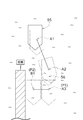
- FIG. 7 is a figure which shows an example of the movement of the ship 95 at the time of carrying out automatic berthing.
- a berth B1 (second position P2) is set near the pier, which is a berthing facility. Further, a via point A3 (first position P1) to be realized immediately before the berth B1 is set at a position offset by an appropriate distance from the berth B1 in a direction perpendicular to the direction of the jetty.
- the target bearing at the waypoint A3 is the same as the target bearing at the berth B1.
- a plurality of waypoints A1 and A2 are defined on the front side of the waypoint A3.
- the ship 95 for which automatic berthing is instructed reaches the first waypoint A1, then moves while turning to reach the next waypoint A2.
- the ship 95 temporarily stops and turns on the spot so that the direction is the same as the target direction of the next waypoint A3.
- the ship 95 translates from the waypoint A2 toward the next waypoint A3.
- the ship 95 moves in parallel from the waypoint A3 toward the docking point B1 while maintaining the current bearing.
- the ship 95 when the ship 95 moves in the order of the waypoint A2, the waypoint A3, and the berthing point B1, the ship 95 does not perform turning and parallel movement at the same time, but only performs parallel movement. Therefore, it is possible to prevent the influence of the lateral fluid force (called cross flow) that occurs when the turning and the parallel movement are performed at the same time. Further, if the turning and the parallel movement are performed at the same time, the thrust generated by the propulsion device 5 can be grasped separately as the thrust for the turning and the thrust for the parallel movement. Since the azimuth of the ship 95 is different from the intended azimuth, the actual direction of the thrust force generated by the marine vessel 95 for the parallel movement also deviates from the intended azimuth.
- the route 56 is formed so as to pass through the waypoint A3 offset from the dock B1 by a predetermined distance in the direction perpendicular to the direction of the jetty.
- the route controller 2 of the present embodiment generates the route 56 that causes the ship 95 to dock at the berthing facility.
- the path 56 includes a first position P1 and a second position P2.
- the first position P1 is a waypoint (a waypoint A7 in the example of FIG. 5; In the example, the waypoint A5, and in the example of FIG. 7, the waypoint A3).
- the second position P2 is the docking point B1 of the ship 95 at the docking facility.
- the route 56 is generated so that the boat 95 moves from the first position P1 to the second position P2 while maintaining the bearing of the boat 95 in the direction along the berthing facility.
- the ship 95 approaches the direction of the berth facility from the first position P1 to the second position P2 while making the direction of the ship 95 coincide with the direction along the berth facility. Therefore, it is possible to accurately and automatically dock the ship 95 while reducing the possibility of collision with the berthing facility.
- the route 56 is generated so as to connect a plurality of positions.
- the first position P1 is immediately before the second position P2 in the order that the ship 95 should realize.
- the route 56 includes one or more waypoints A1, A2,..., A6. These waypoints A1, A2,..., A6 are in front of the waypoint A7 (first position P1) in the order that the ship 95 should realize.
- the route controller 2 can generate the route 56 while switching the azimuth setting mode.
- the azimuth setting mode includes a parallel movement mode after turning on the spot and a turning mode during movement. In the parallel movement mode after turning on the spot, when the vessel 95 reaches a certain waypoint An-1, the waypoint An is set so that the direction of the vessel 95 is adjusted to the direction that the vessel 95 should realize at the next waypoint An. At -1, turn on the spot and move to the next waypoint An while maintaining the bearing after turning.
- the vessel 95 In the moving turning mode, when the vessel 95 reaches a certain waypoint An-1, the vessel 95 is moved from the waypoint An-1 to the next waypoint An and at the same time, the vessel 95 is realized at the next waypoint An. It turns so that the direction of the ship 95 may be adjusted to the desired direction.
- the azimuth setting mode includes an in-situ after-turning forward mode.
- the forward mode after turning on the spot, when the vessel 95 reaches a certain waypoint An-1, it turns on the spot at the waypoint An-1 so that the direction of the vessel 95 is adjusted to the direction to the next waypoint An. , Move to the next waypoint An while maintaining the direction after turning.
- the azimuth setting mode is the straight line distance between the waypoint An-1 and the second position P2 or the straight line between the waypoint An-1 and the first position P1. It is switched based on distance.
- the azimuth setting mode is based on the distance on the route 56 between the waypoint An-1 and the second position P2 or the distance on the route 56 between the waypoint An-1 and the first position P1. It may be switched by.
- the azimuth setting mode is switched based on at least the magnitude of the change in the direction of the route 56 at the waypoint An-1.
- the route controller 2 of this embodiment also includes a display data generation unit 71.
- the display data generation unit 71 generates the display data 75 for graphically displaying the first position P1 and the second position P2, and the directions that the vessel 95 should realize at each of the first position P1 and the second position P2. To generate.
- the route generation unit 51 may generate the route 56 so that the vessel 95 moves in parallel throughout the route 56 from the start end to the end (berthing point B1).
- the direction setting mode may be selected in consideration of whether or not the free space 37 is widely secured around the route 56.
- the marine vessel manipulating control device 1 may acquire, for example, attitude data from an IMU appropriately installed in the ship 95, and use the attitude data to control the operation of the ship 95.
- the position azimuth information input unit 22 may be input with data regarding the current azimuth of the ship 95 obtained from the GNSS device 12 and the IMU.
- the wide area map generation unit 33 may acquire the local map 36 and use the data of the local map 36 to generate a wide area map. Further, the wide area map may be appropriately updated by using the local map 36.
- the map generator 31 may generate an environment map whose coordinates have been converted based on an appropriate method.
- the local map generation unit 32 may generate a local map 36 that is coordinate-converted from the LiDAR coordinate system to the GNSS coordinate system by using the installation position and orientation information of the LiDAR 11. Further, the local map generation unit 32 may use the latitude and longitude data of the GNSS to generate the local map 36 that is coordinate-converted from the GNSS coordinate system to the NEU orthogonal coordinate system.
- the directions of the rotation shafts of the screws 6L and 6R are independently changeable.
- the system of the propulsion device 5 may be changed to another system as long as the lateral translation of the ship 95 and the turning on the spot can be substantially realized.
- the propulsion device 5 can also be configured by one screw whose direction of rotation axis cannot be changed, a rudder, and side thrusters provided on the bow side and the stern side, respectively.
Landscapes
- Engineering & Computer Science (AREA)
- Ocean & Marine Engineering (AREA)
- Remote Sensing (AREA)
- Mechanical Engineering (AREA)
- Combustion & Propulsion (AREA)
- Radar, Positioning & Navigation (AREA)
- Chemical & Material Sciences (AREA)
- Physics & Mathematics (AREA)
- General Physics & Mathematics (AREA)
- Aviation & Aerospace Engineering (AREA)
- Automation & Control Theory (AREA)
- Navigation (AREA)
- Traffic Control Systems (AREA)
- Control Of Position, Course, Altitude, Or Attitude Of Moving Bodies (AREA)
Abstract
Selon la présente invention, un dispositif de commande d'itinéraire génère un itinéraire (56) qui permet à un navire (95) de s'amarrer au niveau d'une installation d'accostage. L'itinéraire (56) comprend un premier emplacement (P1) et un second emplacement (P2). Le premier emplacement (P1) est un point intermédiaire (point intermédiaire (A7) dans l'exemple figurant sur le dessin sélectionné) qui est décalé d'une distance prédéterminée dans une direction qui est orthogonale à la direction dans laquelle l'installation d'accostage est orientée par rapport à un point d'amarrage (B1) (second emplacement (P2)) pour le navire (95) au niveau de l'installation d'accostage. Le second emplacement (P2) correspond au point d'amarrage (B1) pour le navire (95) au niveau de l'installation d'accostage. Le premier emplacement (P1) se trouve juste avant le second emplacement (P2) dans la séquence à réaliser par le navire (95). L'itinéraire (56) est généré de telle sorte que le navire (95) reste orienté dans la direction dans laquelle l'installation d'accostage est orientée à mesure que le navire (95) se déplace du premier emplacement (P1) au second emplacement (P2).
Priority Applications (2)
| Application Number | Priority Date | Filing Date | Title |
|---|---|---|---|
| US17/296,950 US20220028278A1 (en) | 2018-11-27 | 2019-11-26 | Route Generation Device |
| EP19889582.3A EP3889030A4 (fr) | 2018-11-27 | 2019-11-26 | Dispositif de génération d'itinéraire |
Applications Claiming Priority (2)
| Application Number | Priority Date | Filing Date | Title |
|---|---|---|---|
| JP2018-221041 | 2018-11-27 | ||
| JP2018221041A JP7199935B2 (ja) | 2018-11-27 | 2018-11-27 | 経路生成装置 |
Publications (1)
| Publication Number | Publication Date |
|---|---|
| WO2020111040A1 true WO2020111040A1 (fr) | 2020-06-04 |
Family
ID=70854006
Family Applications (1)
| Application Number | Title | Priority Date | Filing Date |
|---|---|---|---|
| PCT/JP2019/046102 WO2020111040A1 (fr) | 2018-11-27 | 2019-11-26 | Dispositif de génération d'itinéraire |
Country Status (4)
| Country | Link |
|---|---|
| US (1) | US20220028278A1 (fr) |
| EP (1) | EP3889030A4 (fr) |
| JP (2) | JP7199935B2 (fr) |
| WO (1) | WO2020111040A1 (fr) |
Families Citing this family (2)
| Publication number | Priority date | Publication date | Assignee | Title |
|---|---|---|---|---|
| WO2023176640A1 (fr) * | 2022-03-15 | 2023-09-21 | パイオニア株式会社 | Dispositif de traitement d'informations, procédé de commande, programme, et support de stockage |
| WO2024049109A1 (fr) * | 2022-08-31 | 2024-03-07 | 씨드로닉스(주) | Procédé de génération de trajet d'accostage et appareil associé |
Citations (4)
| Publication number | Priority date | Publication date | Assignee | Title |
|---|---|---|---|---|
| JP2005255058A (ja) * | 2004-03-12 | 2005-09-22 | Shin Kurushima Dockyard Co Ltd | 船舶の自動着桟係船装置および自動着桟係船方法 |
| JP2016083974A (ja) * | 2014-10-23 | 2016-05-19 | ヤンマー株式会社 | 操船装置 |
| WO2018100749A1 (fr) | 2016-12-02 | 2018-06-07 | ヤマハ発動機株式会社 | Petit navire et son procédé de commande |
| JP2018086988A (ja) * | 2016-11-30 | 2018-06-07 | 三井造船株式会社 | 船舶の操縦システム、船舶、及び船舶の操縦方法 |
Family Cites Families (10)
| Publication number | Priority date | Publication date | Assignee | Title |
|---|---|---|---|---|
| JPH06286694A (ja) * | 1993-04-02 | 1994-10-11 | Japan Hamuwaaji Kk | 船舶の自動着岸・離岸方法 |
| US7389735B2 (en) * | 2005-09-15 | 2008-06-24 | Yamaha Hatsudoki Kubushiki Kaisha | Docking supporting apparatus, and marine vessel including the apparatus |
| JP5000244B2 (ja) * | 2005-09-15 | 2012-08-15 | ヤマハ発動機株式会社 | 着岸支援装置およびそれを備えた船舶 |
| US9778657B2 (en) * | 2010-11-19 | 2017-10-03 | Bradley Tyers | Automatic location placement system |
| US11480965B2 (en) * | 2010-11-19 | 2022-10-25 | Maid Ip Holdings Pty/Ltd | Automatic location placement system |
| JP6286694B2 (ja) | 2015-12-28 | 2018-03-07 | 株式会社ソフイア | 遊技機 |
| US10322787B2 (en) * | 2016-03-01 | 2019-06-18 | Brunswick Corporation | Marine vessel station keeping systems and methods |
| US10429845B2 (en) * | 2017-11-20 | 2019-10-01 | Brunswick Corporation | System and method for controlling a position of a marine vessel near an object |
| US10324468B2 (en) * | 2017-11-20 | 2019-06-18 | Brunswick Corporation | System and method for controlling a position of a marine vessel near an object |
| JP7044018B2 (ja) * | 2018-09-07 | 2022-03-30 | トヨタ自動車株式会社 | 着岸制御装置、船舶、着岸制御方法および着岸制御プログラム |
-
2018
- 2018-11-27 JP JP2018221041A patent/JP7199935B2/ja active Active
-
2019
- 2019-11-26 EP EP19889582.3A patent/EP3889030A4/fr active Pending
- 2019-11-26 US US17/296,950 patent/US20220028278A1/en active Pending
- 2019-11-26 WO PCT/JP2019/046102 patent/WO2020111040A1/fr unknown
-
2022
- 2022-12-22 JP JP2022205802A patent/JP2023024675A/ja active Pending
Patent Citations (4)
| Publication number | Priority date | Publication date | Assignee | Title |
|---|---|---|---|---|
| JP2005255058A (ja) * | 2004-03-12 | 2005-09-22 | Shin Kurushima Dockyard Co Ltd | 船舶の自動着桟係船装置および自動着桟係船方法 |
| JP2016083974A (ja) * | 2014-10-23 | 2016-05-19 | ヤンマー株式会社 | 操船装置 |
| JP2018086988A (ja) * | 2016-11-30 | 2018-06-07 | 三井造船株式会社 | 船舶の操縦システム、船舶、及び船舶の操縦方法 |
| WO2018100749A1 (fr) | 2016-12-02 | 2018-06-07 | ヤマハ発動機株式会社 | Petit navire et son procédé de commande |
Non-Patent Citations (2)
| Title |
|---|
| MISUMI, RYUMA ET AL.: "Subgoal generation in consideration of disturbance in autoberthing system", LECTURE SUMMARIES OF JSME ANNUAL CONFERENCE ON ROBOTICS AND MECHATRONICS, ISSN: 2424-3124 * |
| OKAZAKI, TADATSUGI ET AL.: "A Study on Ship Berthing Support System -Minimum time berthing control", 2008 IEEE INTERNATIONAL CONFERENCE ON SYSTEMS, MAN AND CYBERNETICS, October 2008 (2008-10-01), pages 1522 - 1527, XP031447294, ISSN: 1062-922X * |
Also Published As
| Publication number | Publication date |
|---|---|
| JP7199935B2 (ja) | 2023-01-06 |
| EP3889030A1 (fr) | 2021-10-06 |
| JP2023024675A (ja) | 2023-02-16 |
| EP3889030A4 (fr) | 2022-10-12 |
| JP2020083090A (ja) | 2020-06-04 |
| US20220028278A1 (en) | 2022-01-27 |
Similar Documents
| Publication | Publication Date | Title |
|---|---|---|
| JP6336162B2 (ja) | 改良した船舶操縦方法およびシステム | |
| EP3865395B1 (fr) | Dispositif d'accostage automatique | |
| AU2007256046B2 (en) | Improvements relating to control of marine vessels | |
| EP1365301A2 (fr) | Système et procédé de manoeuvre d'objet mobile | |
| JP2023024675A (ja) | 経路生成装置 | |
| US11597488B2 (en) | Ship maneuvering system, ship, and ship maneuvering method | |
| US20230192262A1 (en) | Automatic guiding method of vessel, automatic guiding program of vessel, automatic guiding system of vessel, and vessel | |
| JP2021500268A (ja) | 横方向及び縦方向の推力を独立して制御するナビゲーションシステム | |
| WO2018123948A1 (fr) | Système de pilotage automatique de vaisseau, vaisseau et procédé de pilotage automatique de vaisseau | |
| WO2018008589A1 (fr) | Système de manœuvre de navire, navire et procédé de manœuvre de navire | |
| JP7417538B2 (ja) | 制御目標生成装置及び操船制御装置 | |
| JP7083049B1 (ja) | 接舷支援システムおよび接舷支援方法 | |
| JP2021020608A (ja) | 船舶位置制御システムと該システムを備えた船舶 | |
| JP2019199238A (ja) | 航走制御方法および航走制御装置 | |
| JP7141777B1 (ja) | 自動着桟機能を有する一軸二舵船 | |
| JP2022139743A (ja) | 経路生成装置、及び、船舶 | |
| JP2023158759A (ja) | 接舷支援システム、接舷支援方法およびプログラム | |
| TW202314286A (zh) | 具有一軸二舵船的操舵角修正功能的操舵系統 |
Legal Events
| Date | Code | Title | Description |
|---|---|---|---|
| 121 | Ep: the epo has been informed by wipo that ep was designated in this application |
Ref document number: 19889582 Country of ref document: EP Kind code of ref document: A1 |
|
| NENP | Non-entry into the national phase |
Ref country code: DE |
|
| ENP | Entry into the national phase |
Ref document number: 2019889582 Country of ref document: EP Effective date: 20210628 |