WO2020100448A1 - 空調用レジスタ - Google Patents
空調用レジスタ Download PDFInfo
- Publication number
- WO2020100448A1 WO2020100448A1 PCT/JP2019/038131 JP2019038131W WO2020100448A1 WO 2020100448 A1 WO2020100448 A1 WO 2020100448A1 JP 2019038131 W JP2019038131 W JP 2019038131W WO 2020100448 A1 WO2020100448 A1 WO 2020100448A1
- Authority
- WO
- WIPO (PCT)
- Prior art keywords
- fin
- air
- downstream
- lower fin
- wall portion
- Prior art date
- Legal status (The legal status is an assumption and is not a legal conclusion. Google has not performed a legal analysis and makes no representation as to the accuracy of the status listed.)
- Ceased
Links
Images





Classifications
-
- B—PERFORMING OPERATIONS; TRANSPORTING
- B60—VEHICLES IN GENERAL
- B60H—ARRANGEMENTS OF HEATING, COOLING, VENTILATING OR OTHER AIR-TREATING DEVICES SPECIALLY ADAPTED FOR PASSENGER OR GOODS SPACES OF VEHICLES
- B60H1/00—Heating, cooling or ventilating devices
- B60H1/34—Nozzles; Air-diffusers
- B60H1/3414—Nozzles; Air-diffusers with means for adjusting the air stream direction
- B60H1/3421—Nozzles; Air-diffusers with means for adjusting the air stream direction using only pivoting shutters
-
- B—PERFORMING OPERATIONS; TRANSPORTING
- B60—VEHICLES IN GENERAL
- B60H—ARRANGEMENTS OF HEATING, COOLING, VENTILATING OR OTHER AIR-TREATING DEVICES SPECIALLY ADAPTED FOR PASSENGER OR GOODS SPACES OF VEHICLES
- B60H1/00—Heating, cooling or ventilating devices
- B60H1/00507—Details, e.g. mounting arrangements, desaeration devices
- B60H1/00557—Details of ducts or cables
- B60H1/00564—Details of ducts or cables of air ducts
Definitions
- the present disclosure blows air for air conditioning sent from an air conditioner into a room from an air outlet provided on a rear wall portion of an instrument panel and changes the blowing direction of the air for air conditioning from the air outlet. For registers.
- the vehicle has a built-in air-conditioning register for changing the direction of the air-conditioning air that is sent from the air-conditioning system and is blown into the passenger compartment from the outlet of the instrument panel.
- the air-conditioning register includes a tubular retainer having a ventilation path for air-conditioning air. Fins extending in the vehicle width direction are arranged in the ventilation passage. The fin is supported by a fin shaft so as to be vertically tiltable with respect to the retainer.
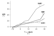
- FIG. 10 shows the result of simulating the relationship between the vertical swing angle of the fin and the directivity angle of the same direction.
- Conventional example 1 shown by a chain double-dashed line in FIG. 10 shows the result of the above-described general air-conditioning register, and the directivity angle increases and decreases as the swing angle increases and decreases.
- the air-conditioning register is generally provided on the upper part of the rear wall of the instrument panel, but the air-conditioning register is installed on the instrument panel in order to make the air outlets invisible to passengers from the viewpoint of design. It may be provided at a lower position of the rear wall portion of the ment panel.
- the variable range of the directional angle is narrowed and the occupant's up / down direction is reduced as in the conventional example 1 of FIG. It is difficult to blow out air-conditioning air toward a wide area in any direction.
- the air conditioning air can be blown toward the region from the abdomen to the throat of the occupant, but the air conditioning air cannot be blown toward the head or the like above it.
- the conventional air-conditioning registers including the above Patent Document 1, which change the flow direction of the air-conditioning air to the upper side by utilizing the Coanda effect, have the following problems.
- Conventional example 2 indicated by a broken line in FIG. 10 shows a result for a conventional air conditioning register in which the Coanda effect occurs.
- the swing angle becomes a predetermined value (10 °) or less.
- the directivity angle increases substantially in proportion to the increase in swing angle.
- the air for air conditioning is blown out in the direction in which the fins are generally oriented.
- An object of the present disclosure is to provide an air-conditioning register that can blow out air-conditioning air toward an arbitrary position on the upper portion of an occupant while expanding the variable range of the directivity angle to the upper side by the Coanda effect. ..
- the air-conditioning register for solving the above-mentioned problems has a ventilation passage for the air-conditioning air, and a downstream end of the ventilation passage in the flow direction of the air-conditioning air has a retainer communicating with the air outlet in the rear wall portion of the instrument panel.
- a portion adjacent to the upper side of the air outlet has an inclined wall portion that is higher toward the downstream side and has an angle of 30 ° to 40 ° with respect to the vertical plane.
- a lower fin extending in the vehicle width direction and an upper fin extending in the vehicle width direction on the upper side of the lower fin are respectively supported on the upstream side of the outlet port by a fin shaft so as to be vertically tiltable.
- the lower ends of the retainer upper wall portion, the upper fins, the lower fins, and the bottom wall portion of the retainer are located on the upstream side, and the lower fins are located on the downstream side.
- the upper fin can be tilted up to 30 ° with respect to the horizontal plane at the maximum, and when the lower fin is tilted by the maximum angle in the higher direction toward the downstream side with respect to the horizontal plane, the upper fin is inclined with respect to the lower fin.
- An interlocking mechanism for interlocking and tilting the upper fin with the lower fin is further provided so that the angle becomes larger than that in the horizontal state, and is provided below the upstream end of the lower fin in the bottom wall portion. Is formed with a slope that is inclined so that it becomes higher toward the downstream side.
- the tilt is transmitted to the upper fin by the interlocking mechanism. It The upper fin is tilted in a direction in which the upper fin moves higher toward the downstream side in conjunction with the lower fin. At this time, the Coanda effect does not occur or is unlikely to occur.
- the conditioned air flows along the lower fin and the upper fin.
- the angle made by the lower fin with respect to the horizontal plane is called the "swing angle”
- the angle made by the air-conditioning air with respect to the horizontal plane is called the "direction angle”.
- the upper fin tilts in conjunction with the lower fin. Since the space between the upper fins and the upper wall of the retainer is narrow, it is difficult for the air-conditioning air to flow between them. Further, the distance between the upper fin and the lower fin is narrowed.
- the lower fin is inclined at the maximum angle in a direction in which the lower fin becomes higher toward the downstream side, the angle of the upper fin in the same direction with respect to the lower fin becomes larger than that in the horizontal state.
- the upstream end of the upper fin approaches the lower fin, and the distance between the two becomes narrower. Air for air conditioning does not easily flow between the upper fin and the lower fin. Therefore, most of the air for air conditioning flows between the lower fin and the bottom wall portion.
- both the lower fin and the upper fin are inclined so that they become higher toward the downstream side.
- the sloped surface provided below the upstream end of the lower fin is inclined so that the slope becomes higher toward the downstream side. Therefore, a part of the air conditioning air that flows near the bottom wall portion inside the retainer flows along the slope, so that the flow direction is inclined so that it becomes higher toward the downstream side.
- This air-conditioning air is guided between the lower fin and the bottom wall that are inclined so that the air becomes higher toward the downstream side. Therefore, a larger amount of the air-conditioning air flows along the lower fins, so that the air-conditioning air flows in an inclined direction so that the air becomes higher toward the downstream side.
- the air-conditioning air that flows in a direction that inclines so that it becomes higher on the downstream side passes through the outlet and then passes through the upper inclined wall.
- the Coanda effect occurs and the air for air conditioning is drawn to the inclined wall portion.
- the air for air conditioning flows in a direction along the inclined wall portion, that is, in a direction in which the air becomes higher toward the downstream side. Therefore, although the air outlet of the air-conditioning register is located in the lower front of the occupant, the air-conditioning air also flows toward the upper part of the occupant's head. In this way, the variable range of the directivity angle is expanded upward.
- the angle formed by the upper fin with respect to the lower fin is larger by 5 ° than the horizontal state by the interlocking mechanism.
- the interlocking mechanism Preferably.
- the angle formed by the upper fin with respect to the lower fin is 5 ° larger at maximum than in the horizontal state. Then, the distance between the upstream end of the upper fin and the lower fin is such that the upstream end is less likely to interfere with the lower fin and air for air conditioning is less likely to pass through.
- the slope is a downstream slope
- the bottom wall portion is provided with a recessed portion that is recessed downward
- the downstream sloped surface is formed in a downstream portion of an inner bottom surface of the recessed portion. It is preferable that an upstream slope that is inclined so as to become lower toward the downstream side is formed upstream of the downstream slope of the inner bottom surface of the.
- the passage between the upper wall portion and the upper fin is restricted, and between the upper fin and the lower fin.
- Most of the air-conditioning air that has been restricted from passing through the space flows between the lower fin and the bottom wall. For this reason, a part of the air-conditioning air that flows near the bottom wall easily enters the recess.
- the air-conditioning air that has entered the recesses is smoothly guided to the downstream slope while the flow direction is changed obliquely downward by flowing along the upstream slope.
- the upstream slope and the downstream slope are connected by a curved surface that is curved so as to bulge downward.
- a part of the air-conditioning air that flows near the bottom wall portion enters the recess and the upstream slope After flowing along the curved surface, it flows along a curved surface that is curved so as to bulge downward, so that it is guided to the downstream slope while gradually changing the flow direction.
- the downstream slope is inclined by 30 ° ⁇ 5 ° with respect to a horizontal plane.
- the angle (30 ° ⁇ 5 °) at which the downstream slope is inclined with respect to the horizontal plane is approximately the same as the angle (30 °) when the lower fin is inclined at the maximum angle.
- the flow direction of the air conditioning air flowing along the downstream slope is substantially the same as the flow direction of the air conditioning air flowing along the lower fin. Therefore, the amount of air conditioning air flowing along the lower fins is further increased.
- the air-conditioning air can be blown out to any position above the occupant while expanding the variable range of the directivity angle upward due to the Coanda effect.
- FIG. 3 is an exploded perspective view of some components of the air conditioning register in the same embodiment.
- FIG. 6 is a side sectional view showing a sectional structure of the air-conditioning register of the embodiment at a portion different from that in FIG.
- FIG. 7 is a side sectional view showing the sectional structure of the air-conditioning register of the same embodiment at a location different from those in FIGS. 5 and 6.
- a partial side cross-sectional view illustrating the positional relationship between the upper and lower fins and the vertical connecting rod when the lower fin is in a horizontal state (swing angle: 0 °).
- a partial side cross-sectional view illustrating the positional relationship between the upper and lower fins and the vertical connecting rod when the lower fin is tilted downward from the horizontal state by the maximum angle (swing angle: 30 °).
- 9 is a graph showing the results of simulating the relationship between the vertical swing angle of the lower fin (fin) and the directivity angle in the same direction for each of the example, the conventional example 1, and the conventional example 2.
- (A)-(d) is a figure for demonstrating the effect
- Explanatory drawing which shows the flow of the air conditioning air blown out from an exit.
- the traveling direction (forward direction) of the vehicle is the front
- the backward direction is the rear
- the height direction is the vertical direction.
- the direction is defined based on the case where the vehicle is viewed from the rear.
- an instrument panel 12 is provided in front of the front seats (driver's seat and passenger seat) of the vehicle 10 over substantially the entire width of the passenger compartment 11.
- Air-conditioning registers 20 are provided in the central portion, both side portions, etc. in the left-right direction of the instrument panel 12.
- the instrument panel 12 is illustrated in a state of being shortened in the left-right direction.
- a part of the rear wall portion 13 of the instrument panel 12 that faces the vehicle interior 11 is inclined so that it is located rearward toward the upper side.
- the rear wall portion 13 is provided with an outlet 14 having a quadrangular shape elongated in the left-right direction rather than the vertical direction in the portion inclined as described above.
- an inclined wall portion 15 is formed at a position adjacent to the upper side of the air outlet 14 in the rear wall portion 13 so that the inclined wall portion 15 is inclined so as to be located rearward toward the upper side.
- the angle ⁇ formed by the inclined wall portion 15 with respect to the vertical plane VS is 30 to 40 °.
- the angle ⁇ is more preferably 31 ° to 36 °.
- the air-conditioning register 20 includes a retainer 21, a downstream fin, a first interlocking mechanism M1, upstream fins 51 and 52, a second interlocking mechanism M2, an operation knob 61, and a transmission mechanism. Equipped with M3.
- the air outlet 14 and the inclined wall portion 15 described above are also used as a part of the air conditioning register 20. Next, each part of the air conditioning register 20 will be described.
- the retainer 21 is for connecting a blower duct (not shown) of the air conditioner and the blowout port 14.
- the internal space of the retainer 21 constitutes a flow path of the air conditioning air A1 sent from the air conditioner through the air duct (hereinafter referred to as “ventilation path 22”).
- ventilation path 22 the air conditioning air A1 sent from the air conditioner through the air duct
- upstream the side closer to the air conditioner
- downstream the side farther from the air conditioner
- downstream side the side farther from the air conditioner
- the inclined wall portion 15 is inclined so that it becomes higher toward the downstream side.
- the downstream end 23 of the retainer 21 is adjacent to the upstream side of the outlet port 14.
- the downstream end of the ventilation path 22 communicates with the air outlet 14.
- the retainer 21 includes a retainer body 24 and a plurality of shims.
- the retainer body 24 constitutes a main part of the retainer 21, and has a tubular shape with an open upstream end and a downstream end.
- the ventilation path 22 is surrounded by the four walls of the retainer 21. These four wall portions connect a pair of vertical wall portions 25 facing each other in the left-right direction, an upper wall portion 26 that connects upper end portions of both vertical wall portions 25, and a lower end portion of both vertical wall portions 25. And a bottom wall portion 27. The downstream end of the upper wall portion 26 is located downstream of the downstream end of the bottom wall portion 27.
- the plurality of shims are composed of a pair of first shims 28 and 29 and a pair of second shims 33 and 34, and are formed of a material softer than the retainer body 24.
- the pair of first shims 28, 29 has a plate shape extending in the vertical direction and the flow direction.
- the first shims 28 and 29 are arranged as a part of the vertical wall portion 25 on both left and right sides of the downstream portion in the retainer body 24.
- the second shims 33, 34 have a plate shape extending in the left-right direction and the flow direction, and are arranged in both upper and lower parts of the retainer body 24.
- the upper second shim 33 constitutes a part of the upper wall portion 26, and the lower second shim 34 constitutes a portion of the bottom wall portion 27.
- Both first shims 28, 29 and both second shims 33, 34 face the air passage 22.
- a bearing hole 31 is formed at two locations vertically spaced apart from each other in the upper downstream portion of each of the first shims 28 and 29.
- the upper bearing hole 31 is formed in the upper ends of the first shims 28 and 29.
- the lower bearing hole 31 is formed in a substantially central portion of the first shims 28, 29 in the vertical direction.
- An arc-shaped guide groove 32 centering on the bearing hole 31 is formed upstream of the lower bearing hole 31 in the first shim 29 on the right side.
- the bearing holes 35 are formed at a plurality of locations that are upstream of the second shim 33 on the upper side and are separated from each other in the left-right direction.
- the lower second shim 34 is formed with a recess 36 that is recessed downward.
- the inner bottom surface of the recess 36 has two slopes adjacent to each other in the flow direction.
- upstream slope 37 the one located on the upstream side
- downstream slope 38 the one located on the downstream side
- the upstream slope 37 is inclined at a constant angle with respect to the horizontal surface HS so that the slope becomes lower toward the downstream side.
- the downstream slope 38 is located below the upstream end of the lower fin 42 described later.
- downstream slope 38 is inclined at a constant angle ⁇ , here 30 ⁇ 5 °, so that it becomes higher toward the downstream side with respect to the horizontal plane HS.
- ⁇ the upstream slope 37 and the downstream slope 38 are connected by a curved surface 40 that is curved so as to bulge downward.
- a bearing hole 39 is formed at an upstream portion of the upstream slope 37 and below the bearing hole 35 of the second shim 33.
- the fins on the downstream side are for changing the direction of the air conditioning air A1 blown out from the air outlet 14 in the up-down direction, and are arranged below the upper fin 41.
- the lower fin 42 that is formed.
- the upper fin 41 is arranged at an upper end portion of the ventilation path 22 and at a position close to the upper wall portion 26 (second shim 33).
- the lower fin 42 is arranged at a substantially central portion of the ventilation path 22 in the vertical direction. The distance between the lower fin 42 and the bottom wall portion 27 when the upper fin 41 and the lower fin 42 are horizontal is wider than the distance between the upper fin 41 and the upper wall portion 26.
- the downstream end of the upper fin 41 is located upstream of the downstream end of the upper wall portion 26.
- the downstream end of the lower fin 42 is located upstream of the downstream end of the upper fin 41 and downstream of the downstream end of the bottom wall portion 27. Further, the downstream end of the lower fin 42 is always located downstream of the upstream end of the upper fin 41 regardless of the inclination of the upper fin 41.
- the downstream ends of the upper wall portion 26, the upper fin 41, the lower fin 42, and the bottom wall portion 27 are located on the upstream side in the downward direction.
- Each of the upper fins 41 and the lower fins 42 includes a fin main body 43 that forms the skeleton of the upper fin 41 and a pair of fin shafts 44.
- each fin main body 43 has a plate shape extending in the left-right direction and the flow direction, and is arranged in the vicinity of the upstream of the outlet port 14.
- the pair of fin shafts 44 are provided at both ends in the left-right direction of the fin body 43 and at the downstream end in the flow direction.
- the pair of fin shafts 44 is provided at both ends in the left-right direction of the fin body 43 and at the downstream end in the flow direction.
- each fin body 43 As shown in FIGS. 4 and 7, at the left end of each fin body 43, a connecting pin 45 is provided at a location that is offset upstream of the fin shaft 44. Both connecting pins 45 are connected by a vertical connecting rod 46.
- a first interlocking mechanism M1 as an interlocking mechanism that mechanically connects the upper fin 41 and the lower fin 42 by the both connecting pins 45 and the vertical connecting rod 46 and tilts the upper fin 41 in conjunction with the lower fin 42 is configured. ing.
- the angle formed by the fins (upper fin 41, lower fin 42) with respect to the horizontal plane HS is called the "swing angle", and the angle formed by the direction in which the air conditioning air A1 blows out with respect to the horizontal plane HS. It is called “directivity angle”.
- the first interlocking mechanism M1 further tilts the upper fin 41 and the lower fin 42 from the horizontal state to the lower side by devising the position of the connecting pin 45 in the upper fin 41 and the lower fin 42.
- the swing angle of the upper fin 41 is set to be larger than the swing angle of the lower fin 42 by at most 5 °.
- the swing angle of the upper fin 41 is set to 35 °. In this way, when the lower fin 42 is tilted by a maximum angle in a direction in which the lower fin 42 becomes higher toward the downstream side with respect to the horizontal plane HS, the angle formed by the upper fin 41 with respect to the lower fin 42 is larger by 5 ° than the horizontal state. Is set to be.
- the upstream fins 51 and 52 are for changing the direction of the air conditioning air A1 blown out from the air outlet 14 in the left-right direction.
- Each of the fins 51 and 52 includes a fin main body 53 that constitutes a main part thereof and a pair of fin shafts 54.
- Each fin body 53 has a plate shape extending in the vertical direction and the flow direction.
- the fin shaft 54 is provided at both ends of the fin body 53 in the vertical direction.
- the fin shafts 54 are engaged with the corresponding bearing holes 35, 39 of the second shims 33, 34, so that the fins 51, 52 are supported so as to be tiltable with respect to the second shims 33, 34. Has been done.
- the fin 51 is located at the center in the left-right direction among the plurality of fins on the upstream side, and includes a cutout portion 55 and a transmission shaft portion 56.
- the transmission shaft portion 56 extends in the vertical direction at the cutout portion 55.
- a connecting pin 57 is provided on the upper end of each fin main body 53 at a position offset to the upstream side of the fin shaft 54.
- the connecting pin 57 of each of the fins 51 and 52 is connected by a horizontal connecting rod 58 extending in the substantially left-right direction.
- the connecting pin 57 and the horizontal connecting rod 58 constitute a second interlocking mechanism M2 that mechanically connects all the fins 51 and 52 and tilts the fins 52 by interlocking with the fins 51.
- the operation knob 61 is a member operated by the occupant P1 when changing the blowing direction of the air conditioning air A1 from the outlet 14.
- the operation knob 61 includes a knob main body 62 that constitutes a main part of the operation knob 61, a knob cover 63 that is attached to the knob main body 62 from the downstream side, and a shim 64.
- the operation knob 61 is attached to the fin body 43 of the lower fin 42 so as to be slidable in the left-right direction.
- the operation knob 61 can tilt together with the lower fin 42 with the fin shaft 44 as a fulcrum.
- the operation knob 61 can be displaced in the left-right direction by sliding on the lower fin 42.
- the shim 64 is attached to the knob body 62 and elastically contacts the fin body 43 of the lower fin 42. Due to this contact, sliding resistance is generated between the shim 64 and the fin body 43 when the operation knob 61 is slid, and an appropriate load is applied.
- the transmission mechanism M3 is a mechanism for transmitting the sliding movement of the operation knob 61 to the fin 51, and includes a fork 65.
- the fork 65 is supported by the knob body 62 by a shaft 66.
- the fork 65 sandwiches the transmission shaft portion 56 of the fin 51 from both left and right sides.
- the fork 65 and the transmission shaft portion 56 of the fin 51 constitute a transmission mechanism M3.
- the air conditioning air A1 flowing between the upper wall portion 26 and the upper fin 41 is small, and most of the air conditioning air A1 that has passed through the upstream fins 51 and 52 is between the upper fin 41 and the lower fin 42. Alternatively, it flows between the lower fin 42 and the bottom wall portion 27. Then, the air conditioning air A1 is blown out from the outlet 14 in a substantially horizontal direction.
- the example shown by the solid line in FIG. 10 shows the result of simulating the relationship between the swing angle of the lower fin in the vertical direction and the directivity angle in the same direction for the air-conditioning register having the same configuration as this embodiment. There is.
- FIG. 11A shows a blowing state of the air conditioning air A1 when the lower fin 42 is in a horizontal state (swing angle: 0 °). From the embodiment of FIG. 10 and FIG. 11A, it can be seen that the air-conditioning air A1 is blown out in a substantially horizontal direction as indicated by an arrow in FIG. 8 although the directivity angle is about 6 °. The air conditioning air A1 is blown out in the direction along the upstream fins 51 and 52 in the left-right direction.
- the lower fin 42 inclines vertically with respect to the horizontal plane HS by an angle larger than 25 °, and the inclined wall portion 15 inclines with respect to the vertical plane VS by an angle obtained by adding 6 ° to 11 ° to the angle. Then, the Coanda effect is said to occur.
- Coanda effect means that the flow of a fluid such as gas or liquid is attracted to a surface that is adjacent to the flow and extends in a direction different from the flow, and flows in the direction along that surface. It is a phenomenon to try.
- the directivity angle changes according to the change, and the directivity angle becomes the same as or equivalent to the swing angle.
- the ratio between the directivity angle and the swing angle becomes substantially constant.
- the air-conditioning air A1 is blown from the outlet 14 in the direction toward the upper fin 41 and the lower fin 42. Therefore, as shown in FIG. 2, it is possible to blow out the air conditioning air A1 toward an arbitrary part of the upper body of the occupant P1 (the upper part of the abdomen PB, the chest PT, the head PH, etc.).
- FIG. 11B shows a blowout state of the air conditioning air A1 when the lower fin 42 is tilted downward by 15 ° from the horizontal state (swing angle: 15 °). From the example of FIG. 10 and FIG. 11B, the directivity angle is about 17 °. It can be seen that the air conditioning air A1 is blown out in substantially the same direction as the inclined direction of the lower fin 42.
- FIG. 11 (c) shows the blowing state of the air conditioning air A1 when the lower fin 42 is tilted downward by 25 ° from the horizontal state (swing angle: 25 °). From the example of FIG. 10 and FIG. 11C, the directivity angle is about 25 °. It can be seen that the air conditioning air A1 is blown out in substantially the same direction as the inclined direction of the lower fin 42.
- the directivity angle changes linearly with the increase or decrease of the swing angle, that is, the directivity angle with respect to the change of the swing angle. It can be seen that the degree of change is constant or substantially constant.
- the upper fin 41 interlocks with the lower fin 42. Tilt down.
- the interval between the upper fin 41 and the upper wall portion 26 becomes narrower than that when the upper fin 41 is in the horizontal state in FIG. 8, and the air conditioning air A1 flows between the upper fin 41 and the upper wall portion 26. Hateful.
- the distance between the upper fin 41 and the lower fin 42 is narrowed.
- the angle formed by the upper fin 41 and the lower fin 42 is larger than that in the horizontal state.
- the upstream end of the upper fin 41 approaches the lower fin 42, and the distance between the two becomes narrower.
- the angle formed by the upper fin 41 and the lower fin 42 is constant, a gap is formed between the upper fin 41 and the lower fin 42, and the air-conditioning air A1 flows through the gap. By reducing the gap, it becomes difficult for the air conditioning air A1 to flow.
- the angle formed by the upper fin 41 and the lower fin 42 is 5 ° larger than that in the horizontal state.
- a distance between the upstream end of the upper fin 41 and the lower fin 42 is such that the upstream end does not easily interfere with the lower fin 42 and the air conditioning air A1 does not easily pass therethrough. Therefore, the air conditioning air A1 does not easily flow between the upstream end of the upper fin 41 and the lower fin 42. The amount of air conditioning air A1 flowing through the gap can be reduced.
- the distance between the lower fin 42 and the bottom wall portion 27 becomes narrower as the lower fin 42 tilts, the distance between the lower fin 42 and the bottom wall portion 27 is different from that between the upper wall portion 26 and the upper fin 41 or between the upper fin 41 and the lower fin 42. Wider than. Therefore, most of the air-conditioning air A1 that is restricted from passing between the upper wall portion 26 and the upper fin 41 and restricted from passing between the upper fin 41 and the lower fin 42 has a lower fin 42 and a bottom wall portion. It flows between 27.
- the downstream slope 38 is not provided below the upstream end of the lower fin 42.
- at least a part of the air conditioning air A1 flows straight to the downstream side along the bottom wall portion 27 even if the lower fin 42 is inclined so as to be higher toward the downstream side.
- the amount of the air-conditioning air A1 whose flow direction can be changed by flowing along the lower fin 42 is reduced.
- the recess 36 is provided in the bottom wall 27 below the upstream end of the lower fin 42. As described above, since most of the air conditioning air A1 flows between the lower fins 42 and the bottom wall portion 27, some of the air conditioning air A1 that flows near the bottom wall portion 27 has a recess 36. Easy to get inside.
- downstream slope 38 is inclined to the side opposite to the upstream slope 37, the upstream slope 37 and the downstream slope 38 are connected by a curved surface 40 that is curved so as to expand downward. Therefore, the air-conditioning air A1 flows along the curved surface 40 and is guided to the downstream slope 38 while gradually changing the flow direction.
- the air-conditioning air A1 flows along the downstream sloped surface 38, so that the flow direction is inclined so that it becomes higher toward the downstream side, and then exits from the recess 36 toward the downstream side. Therefore, the air-conditioning air A1 smoothly flows without changing its flow direction in a period from entering the recess 36, flowing through the recess 36, and exiting the recess 36.
- the air-conditioning air A1 exiting from the recess 36 is guided between the lower fin 42 and the bottom wall portion 27 that are inclined so as to become higher toward the downstream side, and then flows along the lower fin 42.
- the angle ⁇ (30 ° ⁇ 5 °) at which the downstream slope 38 is inclined with respect to the horizontal plane HS is approximately the same as the angle (30 °) when the lower fin 42 is inclined at the maximum angle.
- the flow direction of the air conditioning air A1 flowing along the downstream slope 38 is substantially the same as the flow direction of the air conditioning air A1 flowing along the lower fin 42. Therefore, the amount of the air conditioning air A1 flowing along the lower fin 42 is further increased.
- the air-conditioning air A1 that has passed through the lower fins 42 continues to flow along the upper fins 41, so that the air conditioning air A1 flows in an inclined direction so that it becomes higher toward the downstream side.
- the swing angle is set to be larger than 25 ° and 30 ° or less.
- FIG. 11D shows a blowing state of the air conditioning air A1 when the lower fin 42 is tilted downward from the horizontal state by 30 ° (swing angle: 30 °). From the embodiment of FIG. 10 and FIG. 11D, it can be seen that the directivity angle is about 45 ° and the air conditioning air A1 is blown out above the direction in which the lower fin 42 is inclined.
- the air conditioning air A1 has two points in FIG. As indicated by the chain line, the flow flows from the upper part of the abdomen PB of the occupant P1 to a wide region extending above the head PH.
- the air-conditioning air A1 flows toward a position higher than the head PH. In this case, the air conditioning air A1 does not hit the occupant P1.
- the above embodiment can be implemented as a modified example in which the following modification is made.
- the portion of the bottom wall portion 27 on the upstream side of the downstream slope 38 may be lowered to the same height as the upstream end of the downstream slope 38. In this case, the upstream slope 37 is omitted.
- the fin shafts 44 of the upper fin 41 and the lower fin 42 may be provided at the intermediate portion or the upstream end portion in the flow direction of the air conditioning air A1, instead of the downstream end.
- the downstream slope 38 may be formed by a flat surface, but may be formed by a curved surface that bulges upward or downward on the condition that the downstream slope 38 is inclined so as to be higher on the downstream side as a whole.
- the upstream sloped surface 37 may be formed by a flat surface, but may be formed by a curved surface that bulges upward or downward on the condition that it is inclined so that the downstream side becomes lower as a whole.
- the angle formed by the upper fin 41 and the lower fin 42 is different from that in the horizontal state, and is smaller than 5 °. May be made larger. Also in this case, the distance between the upstream end of the upper fin 41 and the lower fin 42 is such that the upstream end is less likely to interfere with the lower fin 42 and the conditioned air A1 is less likely to pass through.
- the air conditioning register 20 is not limited to a vehicle but can be widely applied to any vehicle provided with the instrument panel 12.
Landscapes
- Physics & Mathematics (AREA)
- Thermal Sciences (AREA)
- Engineering & Computer Science (AREA)
- Mechanical Engineering (AREA)
- Air-Conditioning For Vehicles (AREA)
- Air-Flow Control Members (AREA)
Abstract
インストルメントパネル(12)の後壁部(13)には、吹出口(14)と、その吹出口(14)の上側に隣接し、かつ下流側ほど高くなり、かつ鉛直面(VS)に対しなす角度(α)が30°~40°の傾斜壁部(15)とが形成される。上フィン(41)及び下フィン(42)は、それぞれフィン軸(44)により上下方向に傾動可能に支持される。下フィン(42)は、水平面(HS)に対し最大で30°下側へ傾動可能である。第1連動機構(M1)は、下フィン(42)が下側へ最大角度傾動されたときには、上フィン(41)の下フィン(42)に対しなす角度が、水平状態のときよりも大きくなるように、上フィン(41)を下フィン(42)に連動させて傾動させる。リテーナ(21)の底壁部(27)のうち、下フィン(42)の上流端の下方には、下流側ほど高くなるように傾斜する下流斜面(38)が形成される。
Description
本開示は、空調装置から送られてきた空調用空気を、インストルメントパネルの後壁部に設けられた吹出口から室内に吹き出すとともに、その吹出口からの空調用空気の吹き出し方向を変更する空調用レジスタに関する。
車両には、空調装置から送られてきてインストルメントパネルの吹出口から車室内に吹出す空調用空気の向きを変更等するための空調用レジスタが組込まれている。この空調用レジスタは、空調用空気の通風路を有する筒状のリテーナを備えている。通風路には、車幅方向に延びるフィンが配置されている。フィンは、フィン軸により、リテーナに対し上下方向へ傾動可能に支持されている。
上記空調用レジスタによると、空調装置から空調用空気がリテーナに送られてくると、その空調用空気はフィンに沿って流れ、吹出口から吹き出す。フィンが上下方向へ傾動されると、空調用空気の吹出口からの吹き出し方向が変えられる。ここで、水平面に対しフィンのなす角度を「振り角」といい、水平面に対し空調用空気が吹き出す方向のなす角度を「指向角」というものとする。図10は、フィンの上下方向の振り角と同方向の指向角との関係をシミュレーションした結果を示している。図10において二点鎖線で示す従来例1は、上述した一般的な空調用レジスタについての結果を示しており、振り角の増減に応じて指向角が増減する。
上記空調用レジスタは、一般的には、インストルメントパネルの後壁部の上部に設けられるが、意匠上等の観点から吹出口を乗員の目に付きにくくするために、同空調用レジスタがインストルメントパネルの上記後壁部の低い位置に設けられる場合がある。
この場合、インストルメントパネルの上部に設置される一般的な空調用レジスタの位置を単に低い位置に変えるだけでは、図10の従来例1のように、指向角の可変領域が狭く、乗員の上下方向に広い領域に向けて空調用空気を吹き出させることが難しい。例えば、乗員の腹部から喉元までの領域に向けて空調用空気を吹き出させることができるが、それよりも上側の頭部等に向けて空調用空気を吹き出させることができない。
そのため、特許文献1に記載されているように、吹出口から吹き出された上向きの空調用空気を、コアンダ効果を利用して、インストルメントパネルの後壁部に沿わせることで上方へ向かわせるようにした空調用レジスタが考えられている。この空調用レジスタでは、インストルメントパネルの後壁部のうち、吹出口の上側に隣接する箇所に、下流側ほど高くなるように傾斜する傾斜壁部が形成される。そのため、フィンが下流側ほど高くなるように大きな振り角で傾斜された場合、吹出口から上向きに吹き出された空調用空気は、コアンダ効果によって傾斜壁部に沿って流れることで、コアンダ効果のない場合よりも上側へ向けて流れる。このようにして、指向角の可変領域が上側へ拡大される。
ところが、上記特許文献1を含め、コアンダ効果を利用して空調用空気の流れ方向を上側へ変える従来の空調用レジスタでは、次のような問題があった。
図10において破線で示す従来例2は、コアンダ効果の発生する従来の空調用レジスタについての結果を示している。この空調用レジスタにおいて、フィンを水平な状態(振り角:0°)から、フィンの下流側ほど高くなるように、そのフィンを傾動させていくと、振り角が所定値(10°)以下のときには、指向角は振り角の増加に略比例して増加していく。空調用空気は、概ねフィンの向く方向へ吹き出される。しかし、振り角が上記所定値(10°)よりも大きくなると、コアンダ効果が効き過ぎて指向角が急激に増加する。その結果、空調用空気を、頭部等、乗員の上部の任意の箇所に向けて吹き出させることが難しい。
図10において破線で示す従来例2は、コアンダ効果の発生する従来の空調用レジスタについての結果を示している。この空調用レジスタにおいて、フィンを水平な状態(振り角:0°)から、フィンの下流側ほど高くなるように、そのフィンを傾動させていくと、振り角が所定値(10°)以下のときには、指向角は振り角の増加に略比例して増加していく。空調用空気は、概ねフィンの向く方向へ吹き出される。しかし、振り角が上記所定値(10°)よりも大きくなると、コアンダ効果が効き過ぎて指向角が急激に増加する。その結果、空調用空気を、頭部等、乗員の上部の任意の箇所に向けて吹き出させることが難しい。
本開示の目的は、コアンダ効果により指向角の可変領域を上側へ拡大しつつも、乗員の上部の任意の箇所に向けて空調用空気を吹き出させることのできる空調用レジスタを提供することにある。
上記課題を解決する空調用レジスタは、空調用空気の通風路を有するとともに、空調用空気の流れ方向における前記通風路の下流端が、インストルメントパネルの後壁部における吹出口に連通するリテーナを備え、前記後壁部のうち、前記吹出口の上側に隣接する箇所には、下流側ほど高くなり、かつ鉛直面に対しなす角度が30°~40°の傾斜壁部が形成され、前記リテーナ内であって、前記吹出口の上流側には、車幅方向に延びる下フィンと、前記下フィンの上側で車幅方向に延びる上フィンとが、それぞれフィン軸により上下方向へ傾動可能に支持され、前記リテーナの上壁部、前記上フィン、前記下フィン及び前記リテーナの底壁部の各下流端は、下方に位置するものほど上流側に位置しており、前記下フィンは、下流側ほど高くなる方向へは、水平面に対し最大で30°傾動可能であり、前記下フィンが水平面に対し下流側ほど高くなる方向へ最大角度傾動されたときには、前記上フィンの前記下フィンに対しなす角度が、水平状態のときよりも大きくなるように、前記上フィンを前記下フィンに連動させて傾動させる連動機構がさらに設けられ、前記底壁部のうち、前記下フィンの上流端の下方には、下流側ほど高くなるように傾斜する斜面が形成されている。
上記の構成によれば、下フィンが水平状態から、下流側ほど高くなる方向へ30°近くの角度、例えば25°までの領域で傾動されると、その傾動が連動機構によって上フィンに伝達される。上フィンは下フィンに連動して下流側ほど高くなる方向へ傾動される。このときには、コアンダ効果が発生しない、又は発生しにくい。空調用空気は、下フィン及び上フィンに沿って流れる。
ここで、水平面に対し下フィンのなす角度を「振り角」といい、水平面に対し空調用空気が吹き出す方向のなす角度を「指向角」というものとする。すると、振り角が0°から30°近くの角度、例えば25°までの領域で変化すると、その変化に応じて指向角が変化し、振り角と同一又は同等となる。空調用空気は、吹出口から下フィン及び上フィンの向く方向へ吹き出される。従って、空調用空気を乗員の上部の任意の箇所に向けて吹き出させることが可能である。
振り角が30°近くの角度、例えば25°よりも大きく30°以下となるように、下フィンが傾動されると、上フィンが下フィンに連動して傾動する。上フィンとリテーナの上壁部との間隔が狭く、空調用空気は、両者の間を流れにくい。また、上フィンと下フィンとの間隔が狭まる。下フィンが下流側ほど高くなる方向へ最大角度傾斜したときには、上フィンの下フィンに対し同方向へなす角度が、水平状態のときよりも大きくなる。上フィンの上流端が下フィンに接近し、両者の間隔が狭くなる。空調用空気は、上フィン及び下フィンの間を流れにくい。そのため、空調用空気の多くは、下フィンと底壁部との間を流れる。
ここで、下フィン及び上フィンのいずれも、下流側ほど高くなるように傾斜している。また、底壁部のうち、下フィンの上流端の下方に設けられた斜面は、下流側ほど高くなるように傾斜している。そのため、空調用空気のうちリテーナ内の底壁部の近くを流れるものの一部は斜面に沿って流れることで、流れ方向を、下流側ほど高くなるように傾斜させられる。この空調用空気は、下流側ほど高くなるように傾斜した下フィンと底壁部との間に導かれる。従って、より多くの空調用空気が、下フィンに沿って流れることで、下流側ほど高くなるように傾斜した方向へ流れる。
また、このときには、上記のように下流側ほど高くなるように傾斜する方向へ流れる空調用空気は、吹出口を通過した後に、その上側の傾斜壁部を通過する。この際に、コアンダ効果が発生して、空調用空気が傾斜壁部に引き寄せられる。空調用空気は、傾斜壁部に沿った方向、すなわち、下流側ほど高くなる方向へ向けて流れる。そのため、空調用レジスタの吹出口が、乗員の前下方に位置するものの、空調用空気はその乗員の頭部の上方に向けても流れる。このようにして、指向角の可変領域が上側へ拡大される。
上記空調用レジスタにおいて、前記下フィンが水平面に対し前記最大角度傾動されたときには、前記上フィンの前記下フィンに対しなす角度が、前記連動機構により、水平状態のときよりも最大で5°大きくされることが好ましい。
上記の構成によれば、下フィンが下流側ほど高くなる側へ最大角度傾斜したときには、上フィンの下フィンに対しなす角度が、水平状態のときよりも最大で5°大きくなる。すると、上フィンの上流端と下フィンとの間隔は、同上流端が下フィンと干渉しにくく、また、空調用空気が通過しにくい間隔になる。
上記空調用レジスタにおいて、前記斜面は下流斜面であり、前記底壁部は、下方へ凹む凹部を備えており、前記下流斜面は、前記凹部の内底面の下流部分に形成されており、前記凹部の内底面の前記下流斜面よりも上流には、下流側ほど低くなるように傾斜する上流斜面が形成されていることが好ましい。
上記の構成によれば、下フィンが下流側ほど高くなる方向へ最大角度又は最大角度近く傾斜したときには、上壁部及び上フィンの間での通過を制限され、かつ上フィン及び下フィンの間での通過を制限された空調用空気の多くは、下フィンと底壁部との間を流れる。このことから、空調用空気のうち底壁部の近くを流れるものの一部は、凹部内に入り込みやすい。凹部内に入り込んだ空調用空気は、上流斜面に沿って流れることで、流れ方向を斜め下方へ変えられながら下流斜面にスムーズに導かれる。
上記空調用レジスタにおいて、前記上流斜面及び前記下流斜面は、下側へ膨らむように湾曲する湾曲面により繋がれていることが好ましい。
上記の構成によれば、下フィンが下流側ほど高くなる方向へ最大角度又は最大角度近く傾斜したとき、空調用空気のうち底壁部の近くを流れるものの一部は凹部内に入り込み、上流斜面に沿って流れた後、下方へ膨らむように湾曲する湾曲面に沿って流れることで、流れ方向を徐々に変えられながら下流斜面に導かれる。
上記の構成によれば、下フィンが下流側ほど高くなる方向へ最大角度又は最大角度近く傾斜したとき、空調用空気のうち底壁部の近くを流れるものの一部は凹部内に入り込み、上流斜面に沿って流れた後、下方へ膨らむように湾曲する湾曲面に沿って流れることで、流れ方向を徐々に変えられながら下流斜面に導かれる。
上記空調用レジスタにおいて、前記下流斜面は、水平面に対し30°±5°傾斜していることが好ましい。
上記の構成によれば、下流斜面が水平面に対し傾斜する角度(30°±5°)は、下フィンが最大角度傾斜した場合の角度(30°)と同程度である。下流斜面に沿って流れる空調用空気の流れ方向は、下フィンに沿って流れる空調用空気の流れ方向と略同一となる。そのため、下フィンに沿って流れる空調用空気の量が一層多くなる。
上記の構成によれば、下流斜面が水平面に対し傾斜する角度(30°±5°)は、下フィンが最大角度傾斜した場合の角度(30°)と同程度である。下流斜面に沿って流れる空調用空気の流れ方向は、下フィンに沿って流れる空調用空気の流れ方向と略同一となる。そのため、下フィンに沿って流れる空調用空気の量が一層多くなる。
上記空調用レジスタによれば、コアンダ効果により指向角の可変変域を上側へ拡大しつつも、乗員の上部の任意の箇所に向けて空調用空気を吹き出させることができる。
以下、車両用の空調用レジスタに具体化した一実施形態について、図面を参照して説明する。
なお、以下の記載においては、車両の進行方向(前進方向)を前方とし、後進方向を後方とし、高さ方向を上下方向として説明する。また、車幅方向(左右方向)については、車両を後方から見た場合を基準として方向を規定する。
なお、以下の記載においては、車両の進行方向(前進方向)を前方とし、後進方向を後方とし、高さ方向を上下方向として説明する。また、車幅方向(左右方向)については、車両を後方から見た場合を基準として方向を規定する。
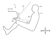
図1及び図2に示すように、車両10の前席(運転席及び助手席)の前方には、車室11の略全幅にわたってインストルメントパネル12が設けられている。インストルメントパネル12の左右方向における中央部、両側部等には空調用レジスタ20が設けられている。なお、図1では、インストルメントパネル12が左右方向に短縮された状態で図示されている。インストルメントパネル12のうち車室11に面する後壁部13の一部は、上側ほど後方に位置するように傾斜している。後壁部13において、上記のように傾斜した部分には、上下方向よりも左右方向に細長い四角形状をなす吹出口14が設けられている。
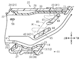
図5に示すように、後壁部13において吹出口14の上側に隣接する箇所には、上側ほど後方に位置するように傾斜する傾斜壁部15が形成されている。傾斜壁部15が鉛直面VSに対しなす角度αは30~40°である。この角度αは、31°~36°であることがより好ましい。
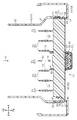
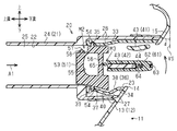
図3~図5に示すように、空調用レジスタ20は、リテーナ21、下流側のフィン、第1連動機構M1、上流側のフィン51,52、第2連動機構M2、操作ノブ61及び伝達機構M3を備えている。上述した吹出口14及び傾斜壁部15も空調用レジスタ20の一部として利用されている。次に、空調用レジスタ20を構成する各部について説明する。
<リテーナ21>
リテーナ21は、空調装置の送風ダクト(図示略)と、上記吹出口14とを繋ぐためのものである。リテーナ21の内部空間は、送風ダクトを通じて空調装置から送られてくる空調用空気A1の流路(以下「通風路22」という)を構成している。ここで、空調用空気A1の流れ方向に関し、空調装置に近い側を「上流」、「上流側」等といい、同空調装置から遠い側を「下流」、「下流側」等というものとする。上流は車両前方と合致し、下流は車両後方と合致する。従って、上記傾斜壁部15は、下流側ほど高くなるように傾斜している。
リテーナ21は、空調装置の送風ダクト(図示略)と、上記吹出口14とを繋ぐためのものである。リテーナ21の内部空間は、送風ダクトを通じて空調装置から送られてくる空調用空気A1の流路(以下「通風路22」という)を構成している。ここで、空調用空気A1の流れ方向に関し、空調装置に近い側を「上流」、「上流側」等といい、同空調装置から遠い側を「下流」、「下流側」等というものとする。上流は車両前方と合致し、下流は車両後方と合致する。従って、上記傾斜壁部15は、下流側ほど高くなるように傾斜している。
リテーナ21がインストルメントパネル12に組み付けられた状態では、同リテーナ21の下流端23は吹出口14の上流側に隣接している。通風路22の下流端は、吹出口14に連通している。
リテーナ21は、リテーナ本体24及び複数のシムを備えている。リテーナ本体24は、リテーナ21の主要部を構成し、上流端と下流端とが開放された筒状をなしている。
通風路22は、リテーナ21の4つの壁部によって取り囲まれている。これらの4つの壁部は、左右方向に相対向する一対の縦壁部25と、両縦壁部25の上端部同士を繋ぐ上壁部26と、両縦壁部25の下端部同士を繋ぐ底壁部27とを備えている。上壁部26の下流端は、底壁部27の下流端よりも下流側に位置している。
通風路22は、リテーナ21の4つの壁部によって取り囲まれている。これらの4つの壁部は、左右方向に相対向する一対の縦壁部25と、両縦壁部25の上端部同士を繋ぐ上壁部26と、両縦壁部25の下端部同士を繋ぐ底壁部27とを備えている。上壁部26の下流端は、底壁部27の下流端よりも下流側に位置している。
複数のシムは、一対の第1シム28,29と、一対の第2シム33,34とからなり、いずれもリテーナ本体24よりも軟質の材料によって形成されている。一対の第1シム28,29は、上下方向及び上記流れ方向に延びる板状をなしている。第1シム28,29は、それぞれ縦壁部25の一部として、リテーナ本体24内の下流部の左右両側部に配置されている。第2シム33,34は、左右方向及び上記流れ方向に延びる板状をなし、リテーナ本体24内の上下両部に配置されている。上側の第2シム33は上壁部26の一部を構成し、下側の第2シム34は底壁部27の一部を構成している。両第1シム28,29及び両第2シム33,34は、通風路22に面している。
各第1シム28,29の下流上部において上下方向に互いに離間した2箇所には、軸受孔31が形成されている。上側の軸受孔31は、第1シム28,29の上端部に形成されている。下側の軸受孔31は、上下方向における第1シム28,29の略中央部分に形成されている。右側の第1シム29であって、下側の軸受孔31よりも上流には、同軸受孔31を中心とする円弧状のガイド溝32が形成されている。
上側の第2シム33の上流部であって、左右方向に互いに離間した複数箇所には軸受孔35が形成されている。下側の第2シム34には、下方へ凹む凹部36が形成されている。図8に示すように、凹部36の内底面は、上記流れ方向に互いに隣接する2つの斜面を有している。これらの斜面を区別するために、上流側に位置するものを「上流斜面37」といい、下流側に位置するものを「下流斜面38」というものとする。上流斜面37は、水平面HSに対し、下流側ほど低くなるように一定の角度で傾斜している。下流斜面38は、後述する下フィン42の上流端の下方に位置している。また、下流斜面38は、水平面HSに対し、下流側ほど高くなるように一定の角度β、ここでは30±5°で傾斜している。図5及び図8に示すように、上流斜面37及び下流斜面38は、下側へ膨らむように湾曲する湾曲面40によって繋がれている。上流斜面37の上流部であって、上記第2シム33の軸受孔35の下方となる箇所には、軸受孔39が形成されている。
<下流側のフィン及び第1連動機構M1>
図3~図5に示すように、下流側のフィンは、吹出口14から吹き出される空調用空気A1の上下方向における向きを変更するためのものであり、上フィン41と、その下方に配置された下フィン42とからなる。上フィン41は、通風路22の上端部分であって、上壁部26(第2シム33)に接近した箇所に配置されている。下フィン42は、上下方向における通風路22の略中央部分に配置されている。上フィン41及び下フィン42が水平状態にされたときの下フィン42と底壁部27との間隔は、上フィン41と上壁部26との間隔よりも広い。
図3~図5に示すように、下流側のフィンは、吹出口14から吹き出される空調用空気A1の上下方向における向きを変更するためのものであり、上フィン41と、その下方に配置された下フィン42とからなる。上フィン41は、通風路22の上端部分であって、上壁部26(第2シム33)に接近した箇所に配置されている。下フィン42は、上下方向における通風路22の略中央部分に配置されている。上フィン41及び下フィン42が水平状態にされたときの下フィン42と底壁部27との間隔は、上フィン41と上壁部26との間隔よりも広い。
上フィン41の下流端は、上壁部26の下流端よりも上流側に位置している。下フィン42の下流端は、上フィン41の下流端よりも上流側であり、かつ底壁部27の下流端よりも下流側に位置している。また、下フィン42の下流端は、上フィン41の傾きに拘わらず、常に上フィン41の上流端よりも下流側に位置している。このように、上壁部26、上フィン41、下フィン42及び底壁部27の各下流端は、下方に位置するものほど上流側に位置している。
上フィン41及び下フィン42の各々は、その骨格部分を構成するフィン本体43と、一対のフィン軸44とを備えている。図3~図6に示すように、各フィン本体43は、左右方向及び上記流れ方向に延びる板状をなしており、吹出口14の上流近傍に配置されている。上フィン41において、一対のフィン軸44は、フィン本体43の左右方向については両端部であって、上記流れ方向については下流端部に設けられている。同様に、下フィン42において、一対のフィン軸44は、フィン本体43の左右方向については両端部であって、上記流れ方向については下流端部に設けられている。そして、各フィン軸44が第1シム28,29の対応する軸受孔31に係合されることにより、上フィン41及び下フィン42は、フィン軸44において第1シム28,29に対し上下方向への傾動可能に支持されている。
図4及び図7に示すように、各フィン本体43の左端部において、上記フィン軸44よりも上流へ偏倚した箇所には、連結ピン45が設けられている。両連結ピン45は、縦連結ロッド46によって連結されている。両連結ピン45及び縦連結ロッド46により、上フィン41及び下フィン42を機械的に連結し、上フィン41を下フィン42に連動させて傾動させる連動機構としての第1連動機構M1が構成されている。
また、図3及び図4に示すように、下フィン42におけるフィン本体43の右端部において、上記フィン軸44よりも上流へ偏倚した箇所にはガイドピン47が設けられている。このガイドピン47は、右側の第1シム29における上記ガイド溝32に係合されている。ガイドピン47は、フィン軸44を支点とした下フィン42の傾動に伴い、ガイド溝32内を上下方向へ移動することを許容される。そして、下フィン42が水平状態から下方へ30°傾動すると、ガイドピン47がガイド溝32の下端に当たり、下フィン42がそれ以上下方へ傾動することを規制される。反対に、下フィン42が水平状態から上方へ所定角度傾動すると、ガイドピン47がガイド溝32の上端に当たり、下フィン42がそれ以上上方へ傾動することを規制される。
ここで、図8に示すように、水平面HSに対しフィン(上フィン41、下フィン42)のなす角度を「振り角」といい、水平面HSに対し空調用空気A1が吹き出す方向のなす角度を「指向角」というものとする。図7に示すように、第1連動機構M1は、さらに、上フィン41及び下フィン42における連結ピン45の位置を工夫することにより、上フィン41及び下フィン42が水平状態から下側へ傾動された場合、振り角の増大に伴い、上フィン41の振り角が下フィン42の振り角よりも最大で5°大きくなるように設定されている。本実施形態では、下フィン42が、水平状態から下側へ最大角度(30°)傾動された場合、上フィン41の振り角が35°となるように設定されている。このように、下フィン42が水平面HSに対し下流側ほど高くなる方向へ最大角度傾動されたときには、上フィン41の下フィン42に対しなす角度が、水平状態のときよりも最大で5°大きくなるように設定されている。
<上流側のフィン51,52及び第2連動機構M2>
図3~図5に示すように、上流側のフィン51,52は、吹出口14から吹出す空調用空気A1の左右方向における向きを変更するためのものである。フィン51,52の各々は、その主要部を構成するフィン本体53と、一対のフィン軸54とを備えている。
図3~図5に示すように、上流側のフィン51,52は、吹出口14から吹出す空調用空気A1の左右方向における向きを変更するためのものである。フィン51,52の各々は、その主要部を構成するフィン本体53と、一対のフィン軸54とを備えている。
各フィン本体53は、上下方向及び上記流れ方向に延びる板状をなしている。フィン51,52の各々において、フィン軸54は、フィン本体53の上下方向の両端部に設けられている。そして、各フィン軸54が、第2シム33,34の対応する軸受孔35,39に係合されることにより、各フィン51,52が、両第2シム33,34に対し傾動可能に支持されている。
フィン51は、上流側の複数のフィンのうち、左右方向における中央に位置するものであり、切欠き部55及び伝達軸部56を備えている。伝達軸部56は、切欠き部55において上下方向へ延びている。
各フィン本体53の上端部において、上記フィン軸54よりも上流へ偏倚した箇所には、連結ピン57が設けられている。フィン51,52毎の連結ピン57は、略左右方向へ延びる横連結ロッド58によって連結されている。上記連結ピン57及び横連結ロッド58により、全てのフィン51,52を機械的に連結し、フィン52をフィン51に連動させて傾動させる第2連動機構M2が構成されている。
<操作ノブ61>
操作ノブ61は、吹出口14からの空調用空気A1の吹出し方向を変更する際に乗員P1によって操作される部材である。操作ノブ61は、その主要部を構成するノブ本体62と、ノブ本体62に対し下流側から装着されるノブカバー63と、シム64とを備えている。操作ノブ61は、下フィン42のフィン本体43に対し左右方向へスライド可能に装着されている。操作ノブ61は、下フィン42と一緒に、フィン軸44を支点として傾動可能である。また、操作ノブ61は、下フィン42上をスライドすることで、左右方向へ変位可能である。シム64は、ノブ本体62に装着されており、下フィン42のフィン本体43に弾性的に接触されている。この接触により、操作ノブ61がスライドされたときにシム64とフィン本体43との間に摺動抵抗が発生し、適度な荷重が付与される。
操作ノブ61は、吹出口14からの空調用空気A1の吹出し方向を変更する際に乗員P1によって操作される部材である。操作ノブ61は、その主要部を構成するノブ本体62と、ノブ本体62に対し下流側から装着されるノブカバー63と、シム64とを備えている。操作ノブ61は、下フィン42のフィン本体43に対し左右方向へスライド可能に装着されている。操作ノブ61は、下フィン42と一緒に、フィン軸44を支点として傾動可能である。また、操作ノブ61は、下フィン42上をスライドすることで、左右方向へ変位可能である。シム64は、ノブ本体62に装着されており、下フィン42のフィン本体43に弾性的に接触されている。この接触により、操作ノブ61がスライドされたときにシム64とフィン本体43との間に摺動抵抗が発生し、適度な荷重が付与される。
<伝達機構M3>
伝達機構M3は、操作ノブ61のスライド動作をフィン51に伝達するための機構であり、フォーク65を備えている。フォーク65は、軸66によりノブ本体62に支持されている。フォーク65は、上記フィン51の伝達軸部56を左右両側から挟み込んでいる。フォーク65及びフィン51の伝達軸部56により伝達機構M3が構成されている。
伝達機構M3は、操作ノブ61のスライド動作をフィン51に伝達するための機構であり、フォーク65を備えている。フォーク65は、軸66によりノブ本体62に支持されている。フォーク65は、上記フィン51の伝達軸部56を左右両側から挟み込んでいる。フォーク65及びフィン51の伝達軸部56により伝達機構M3が構成されている。
次に、上記のようにして構成された本実施形態の空調用レジスタ20の作用及び効果について説明する。
図4において、操作ノブ61がフィン本体43における左右方向の中央部に位置するときには、フィン51,52が両縦壁部25に対し平行な状態(中立状態)になる。この中立状態から操作ノブ61が下フィン42に沿って左方又は右方へスライド操作されると、その操作ノブ61の動きが伝達機構M3におけるフォーク65及び伝達軸部56を通じてフィン51に伝達される。フィン51が両フィン軸54を支点として操作ノブ61のスライド方向と同方向へ傾動させられる。フィン51の傾動は、第2連動機構M2を介して全てのフィン52に伝達される。その結果、フィン51に連動して、全てのフィン52が両フィン軸54を支点としてフィン51と同方向へ傾動させられる。空調用空気A1は、フィン51,52に沿って流れる。
図4において、操作ノブ61がフィン本体43における左右方向の中央部に位置するときには、フィン51,52が両縦壁部25に対し平行な状態(中立状態)になる。この中立状態から操作ノブ61が下フィン42に沿って左方又は右方へスライド操作されると、その操作ノブ61の動きが伝達機構M3におけるフォーク65及び伝達軸部56を通じてフィン51に伝達される。フィン51が両フィン軸54を支点として操作ノブ61のスライド方向と同方向へ傾動させられる。フィン51の傾動は、第2連動機構M2を介して全てのフィン52に伝達される。その結果、フィン51に連動して、全てのフィン52が両フィン軸54を支点としてフィン51と同方向へ傾動させられる。空調用空気A1は、フィン51,52に沿って流れる。
一方、図5~図8に示すように、下フィン42が水平状態のときには、上フィン41が同様に水平状態となる。そのため、空調装置からリテーナ21に送れられてきた空調用空気A1は、リテーナ21の上壁部26と上フィン41との間、上フィン41と下フィン42との間、下フィン42と底壁部27との間を流れる。ただし、上壁部26と上フィン41との間隔は、上フィン41と下フィン42との間隔や、下フィン42と底壁部27との間隔に比べると狭い。そのため、上壁部26と上フィン41との間を流れる空調用空気A1は少なく、上流側のフィン51,52を通過した空調用空気A1の多くは、上フィン41と下フィン42との間や、下フィン42と底壁部27との間を流れる。そして、空調用空気A1は、吹出口14から略水平方向へ吹き出される。図10において実線で示す実施例は、本実施形態と同様の構成を有する空調用レジスタを対象とし、下フィンの上下方向の振り角と同方向の指向角との関係をシミュレーションした結果を示している。
また、図11(a)は、下フィン42を水平状態にした場合(振り角:0°)の空調用空気A1の吹き出し状態を示している。図10の実施例、及び図11(a)から、指向角が6°前後であるが、空調用空気A1は図8において矢印で示すように、概ね水平方向へ吹き出されることが判る。なお、空調用空気A1は、左右方向については、上流側のフィン51,52に沿う方向へ吹き出される。
上記の水平状態から図5における操作ノブ61の下流端に対し、矢印で示すように上方へ向かう力が加えられると、その力が下フィン42に伝達される。下フィン42がフィン軸44を支点として、上流側ほど低くなるように下側へ傾動させられる。
水平状態から下側へ30°近くの角度、ここでは25°までの領域で、下フィン42が傾動されると、その傾動が第1連動機構M1によって上フィン41に伝達される。上フィン41は下フィン42に連動して下側へ傾動される。
ここで、一般に、下フィン42が水平面HSに対し上下方向へ25°よりも大きな角度傾斜し、かつその角度に対し6°~11°加算した角度だけ傾斜壁部15が鉛直面VSに対し傾斜すると、コアンダ効果が発生するものとされている。
なお、ここでいう「コアンダ効果」とは、気体、液体等の流体の流れが、その流れの傍にあってその流れと異なる方向に延びる面に引き寄せられて、その面に沿った方向へ流れようとする現象のことである。
そのため、下フィン42が上記のように水平状態と、水平状態から下側へ30°近くの角度(25°)までの領域で傾動し、それに連動して上フィン41が傾動する場合には、コアンダ効果が発生しない、又は発生しにくい。空調用空気A1は、下フィン42及び上フィン41に沿って流れる。
ここで、上記のように振り角が0°から25°までの領域で変化すると、その変化に応じて指向角が変化し、同指向角は振り角と同一又は同等となる。表現を変えると、指向角と振り角との比が略一定となる。空調用空気A1は、吹出口14から上フィン41及び下フィン42の向く方向へ吹き出される。従って、図2に示すように、空調用空気A1を乗員P1の上半身(腹部PBの上部、胸部PT、頭部PH等)の任意の箇所に向けて吹き出させることが可能である。
図11(b)は、下フィン42が水平状態から下側へ15°傾動された場合(振り角:15°)の空調用空気A1の吹き出し状態を示している。図10の実施例、及び図11(b)から、指向角が17°程度となる。空調用空気A1は、下フィン42の傾斜した方向と概ね同じ方向へ吹き出されることが判る。
図11(c)は、下フィン42が水平状態から下側へ25°傾動された場合(振り角:25°)の空調用空気A1の吹き出し状態を示している。図10の実施例、及び図11(c)から、指向角が25°程度となる。空調用空気A1は、下フィン42の傾斜した方向と概ね同じ方向へ吹き出されることが判る。
さらに、図10の実施例からは、下フィン42の振り角が0°から25°までの領域では、振り角の増減に伴い指向角がリニアに変化、すなわち、振り角の変化に対する指向角の変化の度合いが一定又は略一定となることが判る。
これに対し、振り角が25°よりも大きく30°以下となるように、図9に示すように、下フィン42が下側へ傾動されると、上フィン41が下フィン42に連動して下側へ傾動する。上フィン41と上壁部26との間隔は、上フィン41が図8の水平状態であるときよりもさらに狭くなり、空調用空気A1は、上フィン41と上壁部26との間を流れにくい。
また、上フィン41と下フィン42との間隔が狭まる。また、このときには、上フィン41の下フィン42に対しなす角度が、水平状態のときよりも大きくなる。上フィン41の上流端が下フィン42に接近し、両者の間隔が狭くなる。上フィン41の下フィン42に対しなす角度が一定である場合には、上フィン41及び下フィン42の間に少なからず隙間ができ、空調用空気A1がその隙間を流れるが、本実施形態では、隙間を小さくすることで、空調用空気A1が流れにくくなる。
特に、本実施形態では、下フィン42が下側へ最大角度(30°)傾斜したときには、上フィン41の下フィン42に対しなす角度が、水平状態のときよりも5°大きくなる。上フィン41の上流端と下フィン42との間隔は、同上流端が下フィン42と干渉しにくく、また、空調用空気A1が通過しにくい間隔になる。従って、空調用空気A1は、上フィン41の上流端と下フィン42との間を流れにくい。上記隙間を流れる空調用空気A1の量を少なくすることができる。
下フィン42と底壁部27との間隔は、同下フィン42の傾動に伴い狭くなるものの、その間隔は、上壁部26と上フィン41との間隔や、上フィン41と下フィン42との間隔よりも広い。そのため、上壁部26及び上フィン41の間での通過を制限され、上フィン41及び下フィン42の間での通過を制限された空調用空気A1の多くは、下フィン42と底壁部27との間を流れる。
ここで、仮に、底壁部27のうち、下フィン42の上流端の下方に下流斜面38が設けられていないものとする。この場合には、たとえ下フィン42が下流側ほど高くなるように傾斜したとしても、空調用空気A1の少なくとも一部が底壁部27に沿って下流側へ真っ直ぐ流れてしまう。その分、下フィン42に沿って流れることで流れ方向を変えられる空調用空気A1の量が少なくなる。
この点、本実施形態では、底壁部27のうち、下フィン42の上流端の下方に凹部36が設けられている。上述したように、空調用空気A1の多くが下フィン42と底壁部27との間を流れることから、同空調用空気A1のうち底壁部27の近くを流れるものの一部は、凹部36内に入り込みやすい。
上述したように、上流斜面37は、水平面HSに対し、下流側ほど低くなるように一定の角度で傾斜している。凹部36に形成された下流斜面38は、水平面HSに対し、下流側ほど高くなるように一定の角度βで傾斜している。上流斜面37の上流端は凹部36の上流端に位置し、下流斜面38の下流端は凹部36の下流端に位置している。そのため、凹部36内に入り込んだ空調用空気A1は、上流斜面37に沿って流れることで、流れ方向を急激に変えられることなく斜め下方へ変えられながら下流斜面38に導かれる。
さらに、下流斜面38が上流斜面37とは反対側へ傾いているものの、上流斜面37及び下流斜面38が、下方へ膨らむように湾曲する湾曲面40によって繋がれている。そのため、空調用空気A1は湾曲面40に沿って流れることで、流れ方向を徐々に変えられながら下流斜面38に導かれる。
空調用空気A1は、下流斜面38に沿って流れることで、流れ方向を、下流側ほど高くなるように傾斜させられた後、凹部36から下流側へ出る。
従って、空調用空気A1は、凹部36に入り込み、凹部36内を流れ、凹部36から出るまでの期間において、急激に流れ方向を変えられることがなくスムーズに流れる。
従って、空調用空気A1は、凹部36に入り込み、凹部36内を流れ、凹部36から出るまでの期間において、急激に流れ方向を変えられることがなくスムーズに流れる。
凹部36から出た空調用空気A1は、下流側ほど高くなるように傾斜した下フィン42と底壁部27との間に導かれた後、同下フィン42に沿って流れる。
上記下流斜面38が水平面HSに対し傾斜する角度β(30°±5°)は、下フィン42が最大角度傾斜した場合の角度(30°)と同程度である。下流斜面38に沿って流れる空調用空気A1の流れ方向は、下フィン42に沿って流れる空調用空気A1の流れ方向と略同一となる。そのため、下フィン42に沿って流れる空調用空気A1の量が一層多くなる。
上記下流斜面38が水平面HSに対し傾斜する角度β(30°±5°)は、下フィン42が最大角度傾斜した場合の角度(30°)と同程度である。下流斜面38に沿って流れる空調用空気A1の流れ方向は、下フィン42に沿って流れる空調用空気A1の流れ方向と略同一となる。そのため、下フィン42に沿って流れる空調用空気A1の量が一層多くなる。
下フィン42を通過した空調用空気A1は、引き続き上フィン41に沿って流れることで、さらに下流側ほど高くなるように傾斜した方向へ流れる。
一方で、傾斜壁部15が鉛直面VSに対し30°~40°傾斜している本実施形態の空調用レジスタ20にあって、振り角が25°よりも大きく30°以下となるように、下フィン42が下側へ傾動されると、コアンダ効果が発生する。そのため、上記のように下流側ほど高くなるように傾斜する方向へ流れる空調用空気A1は、吹出口14を通過した後に、その上側の傾斜壁部15を通過する際に、同傾斜壁部15に引き寄せられる。空調用空気A1は、傾斜壁部15に沿った方向、すなわち、下流側ほど高くなる方向へ向けて流れる。
一方で、傾斜壁部15が鉛直面VSに対し30°~40°傾斜している本実施形態の空調用レジスタ20にあって、振り角が25°よりも大きく30°以下となるように、下フィン42が下側へ傾動されると、コアンダ効果が発生する。そのため、上記のように下流側ほど高くなるように傾斜する方向へ流れる空調用空気A1は、吹出口14を通過した後に、その上側の傾斜壁部15を通過する際に、同傾斜壁部15に引き寄せられる。空調用空気A1は、傾斜壁部15に沿った方向、すなわち、下流側ほど高くなる方向へ向けて流れる。
図11(d)は、下フィン42が水平状態から下側へ30°傾動された場合(振り角:30°)の空調用空気A1の吹き出し状態を示している。図10の実施例及び図11(d)から、指向角が45°程度となり、空調用空気A1は、下フィン42の傾斜した方向よりも上側へ吹き出されることが判る。
そのため、図2に示すように、空調用レジスタ20の吹出口14が、乗員P1の前下方(腹部PBや胸部PTの前方)に位置するものの、空調用空気A1は、同図2において二点鎖線で示すように、乗員P1の腹部PBの上部から頭部PHよりも高い箇所にわたる広い領域に向けて流れる。下フィン42を下側へ最大角度傾斜させた場合には、空調用空気A1は頭部PHよりも高い箇所に向けて流れる。この場合には、空調用空気A1は乗員P1には当たらない。このように、本実施形態によると、コアンダ効果により上下方向の指向角の可変領域を上側へ拡大しつつも、乗員P1の上部の任意の箇所に向けて空調用空気A1を吹き出させることができる。
以上は、下フィン42を水平状態(振り角:0°)から下側へ傾動させた場合についての作用及び効果であるが、下フィン42が下側へ最大角度(振り角:30°)傾斜させられた状態から上側へ傾動されて水平状態に戻される場合についても、上記と同様の作用及び効果が得られる。そのため、詳細については説明を省略する。
なお、上記実施形態は、これを以下のように変更した変形例として実施することもできる。
・底壁部27において下流斜面38よりも上流側の部分が、同下流斜面38の上流端と同じ高さまで下げられてもよい。この場合には、上流斜面37が省略される。
・底壁部27において下流斜面38よりも上流側の部分が、同下流斜面38の上流端と同じ高さまで下げられてもよい。この場合には、上流斜面37が省略される。
・上フィン41及び下フィン42におけるフィン軸44が、下流端に代えて、空調用空気A1の流れ方向における中間部分や上流端部に設けられてもよい。
・下流斜面38は、平面によって構成されてもよいが、全体として下流側ほど高くなるように傾斜することを条件に、上方又は下方へ膨らむ湾曲面によって構成されてもよい。同様に、上流斜面37は、平面によって構成されてもよいが、全体として下流側ほど低くなるように傾斜することを条件に、上方又は下方へ膨らむ湾曲面によって構成されてもよい。
・下流斜面38は、平面によって構成されてもよいが、全体として下流側ほど高くなるように傾斜することを条件に、上方又は下方へ膨らむ湾曲面によって構成されてもよい。同様に、上流斜面37は、平面によって構成されてもよいが、全体として下流側ほど低くなるように傾斜することを条件に、上方又は下方へ膨らむ湾曲面によって構成されてもよい。
・下フィン42が水平面HSに対し下側へ最大角度傾斜したときには、上フィン41の下フィン42に対しなす角度が、水平状態のときとは異なる角度であって、5°よりも小さい角度だけ大きくされてもよい。この場合にも、上フィン41の上流端と下フィン42との間隔は、同上流端が下フィン42と干渉しにくく、また、空調用空気A1が通過しにくい間隔になる。
・上記空調用レジスタ20は、インストルメントパネル12が設けられた乗物であれば、車両に限らず広く適用可能である。
12…インストルメントパネル、13…後壁部、14…吹出口、15…傾斜壁部、20…空調用レジスタ、21…リテーナ、22…通風路、23…下流端、26…上壁部、27…底壁部、36…凹部、37…上流斜面、38…下流斜面(斜面)、40…湾曲面、41…上フィン、42…下フィン、44…フィン軸、A1…空調用空気、HS…水平面、M1…第1連動機構(連動機構)、VS…鉛直面、α,β…角度。
Claims (5)
- 空調用空気の通風路を有するとともに、空調用空気の流れ方向における前記通風路の下流端が、インストルメントパネルの後壁部における吹出口に連通するリテーナを備え、
前記後壁部のうち、前記吹出口の上側に隣接する箇所には、下流側ほど高くなり、かつ鉛直面に対しなす角度が30°~40°の傾斜壁部が形成され、
前記リテーナ内であって、前記吹出口の上流側には、車幅方向に延びる下フィンと、前記下フィンの上側で車幅方向に延びる上フィンとが、それぞれフィン軸により上下方向へ傾動可能に支持され、
前記リテーナの上壁部、前記上フィン、前記下フィン及び前記リテーナの底壁部の各下流端は、下方に位置するものほど上流側に位置しており、
前記下フィンは、下流側ほど高くなる方向へは、水平面に対し最大で30°傾動可能であり、
前記下フィンが水平面に対し下流側ほど高くなる方向へ最大角度傾動されたときには、前記上フィンの前記下フィンに対しなす角度が、水平状態のときよりも大きくなるように、前記上フィンを前記下フィンに連動させて傾動させる連動機構がさらに設けられ、
前記底壁部のうち、前記下フィンの上流端の下方には、下流側ほど高くなるように傾斜する斜面が形成されている空調用レジスタ。 - 前記下フィンが水平面に対し前記最大角度傾動されたときには、前記上フィンの前記下フィンに対しなす角度が、前記連動機構により、水平状態のときよりも最大で5°大きくされる請求項1に記載の空調用レジスタ。
- 前記斜面は下流斜面であり、
前記底壁部は、下方へ凹む凹部を備えており、
前記下流斜面は、前記凹部の内底面の下流部分に形成されており、
前記凹部の内底面の前記下流斜面よりも上流には、下流側ほど低くなるように傾斜する上流斜面が形成されている請求項1又は2に記載の空調用レジスタ。 - 前記上流斜面及び前記下流斜面は、下側へ膨らむように湾曲する湾曲面により繋がれている請求項3に記載の空調用レジスタ。
- 前記下流斜面は、水平面に対し30°±5°傾斜している請求項3又は4に記載の空調用レジスタ。
Priority Applications (2)
| Application Number | Priority Date | Filing Date | Title |
|---|---|---|---|
| US17/290,405 US11904661B2 (en) | 2018-11-15 | 2019-09-27 | Register for air-conditioning |
| CN201980074845.6A CN113015642B (zh) | 2018-11-15 | 2019-09-27 | 空调用调节器 |
Applications Claiming Priority (2)
| Application Number | Priority Date | Filing Date | Title |
|---|---|---|---|
| JP2018214912A JP7124662B2 (ja) | 2018-11-15 | 2018-11-15 | 空調用レジスタ |
| JP2018-214912 | 2018-11-15 |
Publications (1)
| Publication Number | Publication Date |
|---|---|
| WO2020100448A1 true WO2020100448A1 (ja) | 2020-05-22 |
Family
ID=70731380
Family Applications (1)
| Application Number | Title | Priority Date | Filing Date |
|---|---|---|---|
| PCT/JP2019/038131 Ceased WO2020100448A1 (ja) | 2018-11-15 | 2019-09-27 | 空調用レジスタ |
Country Status (4)
| Country | Link |
|---|---|
| US (1) | US11904661B2 (ja) |
| JP (1) | JP7124662B2 (ja) |
| CN (1) | CN113015642B (ja) |
| WO (1) | WO2020100448A1 (ja) |
Citations (3)
| Publication number | Priority date | Publication date | Assignee | Title |
|---|---|---|---|---|
| JP2011079374A (ja) * | 2009-10-05 | 2011-04-21 | Howa Kasei Kk | 空気吹出装置 |
| JP2013006569A (ja) * | 2011-06-27 | 2013-01-10 | Toyoda Gosei Co Ltd | 空調用レジスタ |
| JP2017024555A (ja) * | 2015-07-22 | 2017-02-02 | 豊田合成株式会社 | 空調用レジスタ |
Family Cites Families (5)
| Publication number | Priority date | Publication date | Assignee | Title |
|---|---|---|---|---|
| JP5864233B2 (ja) | 2011-12-01 | 2016-02-17 | 豊和化成株式会社 | レジスタ |
| JP2015163489A (ja) | 2014-02-28 | 2015-09-10 | ダイキョーニシカワ株式会社 | 送風装置 |
| JP6350341B2 (ja) * | 2015-03-04 | 2018-07-04 | 豊田合成株式会社 | 空調用レジスタ |
| KR101763671B1 (ko) * | 2016-06-29 | 2017-08-01 | 주식회사 제이피씨오토모티브 | 콤팩트한 구성이 가능한 차량 공기조화용 풍향조절장치 |
| JP2018047785A (ja) * | 2016-09-21 | 2018-03-29 | 豊田合成株式会社 | 空調用レジスタ |
-
2018
- 2018-11-15 JP JP2018214912A patent/JP7124662B2/ja active Active
-
2019
- 2019-09-27 CN CN201980074845.6A patent/CN113015642B/zh active Active
- 2019-09-27 US US17/290,405 patent/US11904661B2/en active Active
- 2019-09-27 WO PCT/JP2019/038131 patent/WO2020100448A1/ja not_active Ceased
Patent Citations (3)
| Publication number | Priority date | Publication date | Assignee | Title |
|---|---|---|---|---|
| JP2011079374A (ja) * | 2009-10-05 | 2011-04-21 | Howa Kasei Kk | 空気吹出装置 |
| JP2013006569A (ja) * | 2011-06-27 | 2013-01-10 | Toyoda Gosei Co Ltd | 空調用レジスタ |
| JP2017024555A (ja) * | 2015-07-22 | 2017-02-02 | 豊田合成株式会社 | 空調用レジスタ |
Also Published As
| Publication number | Publication date |
|---|---|
| JP7124662B2 (ja) | 2022-08-24 |
| US20210354533A1 (en) | 2021-11-18 |
| JP2020082762A (ja) | 2020-06-04 |
| CN113015642A (zh) | 2021-06-22 |
| US11904661B2 (en) | 2024-02-20 |
| CN113015642B (zh) | 2024-03-12 |
Similar Documents
| Publication | Publication Date | Title |
|---|---|---|
| JP6100202B2 (ja) | 空調用レジスタ | |
| US20160009163A1 (en) | Air conditioning thin register | |
| US10099534B2 (en) | Air-conditioning register | |
| JP2015044505A (ja) | 空調用レジスタ | |
| JP6350341B2 (ja) | 空調用レジスタ | |
| JP6500234B2 (ja) | 空調用薄型レジスタ | |
| JP6791066B2 (ja) | 空調用薄型レジスタ | |
| JP2023138816A (ja) | 空調用薄型レジスタ | |
| JP7124662B2 (ja) | 空調用レジスタ | |
| JP6985162B2 (ja) | 空調用レジスタ | |
| JP5842787B2 (ja) | 空調用レジスタ | |
| JP6048356B2 (ja) | 空調用レジスタ | |
| JP6817177B2 (ja) | 空調用レジスタ | |
| JP2015078787A (ja) | 空調用レジスタ | |
| JP7239890B2 (ja) | 空調用レジスタ | |
| JP7600974B2 (ja) | 車両用空調装置 | |
| JP5852710B2 (ja) | 空調用レジスタ | |
| JP2013006569A (ja) | 空調用レジスタ | |
| JP6800465B2 (ja) | 空調用レジスタ | |
| JP2023087319A (ja) | 車両用空調装置 | |
| JP6817178B2 (ja) | 空調用レジスタ | |
| JP6769275B2 (ja) | 空調用レジスタ | |
| CN115675021A (zh) | 空调装置的吹出构造体 | |
| CN115675020A (zh) | 空调装置的吹出构造体 | |
| JP2018103864A (ja) | 車両用レジスタ装置 |
Legal Events
| Date | Code | Title | Description |
|---|---|---|---|
| 121 | Ep: the epo has been informed by wipo that ep was designated in this application |
Ref document number: 19884489 Country of ref document: EP Kind code of ref document: A1 |
|
| NENP | Non-entry into the national phase |
Ref country code: DE |
|
| 122 | Ep: pct application non-entry in european phase |
Ref document number: 19884489 Country of ref document: EP Kind code of ref document: A1 |