WO2020090792A1 - Membrane microporeuse en polyoléfine et filtre à liquide - Google Patents
Membrane microporeuse en polyoléfine et filtre à liquide Download PDFInfo
- Publication number
- WO2020090792A1 WO2020090792A1 PCT/JP2019/042303 JP2019042303W WO2020090792A1 WO 2020090792 A1 WO2020090792 A1 WO 2020090792A1 JP 2019042303 W JP2019042303 W JP 2019042303W WO 2020090792 A1 WO2020090792 A1 WO 2020090792A1
- Authority
- WO
- WIPO (PCT)
- Prior art keywords
- polyolefin
- microporous membrane
- crystals
- porous layer
- rod
- Prior art date
Links
- 229920000098 polyolefin Polymers 0.000 title claims abstract description 143
- 239000012982 microporous membrane Substances 0.000 title claims abstract description 106
- 239000007788 liquid Substances 0.000 title claims description 79
- 239000013078 crystal Substances 0.000 claims abstract description 195
- LFQSCWFLJHTTHZ-UHFFFAOYSA-N Ethanol Chemical compound CCO LFQSCWFLJHTTHZ-UHFFFAOYSA-N 0.000 claims description 38
- 239000012528 membrane Substances 0.000 claims description 34
- 239000011148 porous material Substances 0.000 claims description 26
- 239000000758 substrate Substances 0.000 claims description 15
- 101100453790 Drosophila melanogaster Kebab gene Proteins 0.000 claims description 13
- 235000015231 kebab Nutrition 0.000 claims description 13
- 239000010410 layer Substances 0.000 description 143
- -1 polyethylene Polymers 0.000 description 89
- 239000004698 Polyethylene Substances 0.000 description 87
- 229920000573 polyethylene Polymers 0.000 description 87
- 239000010408 film Substances 0.000 description 38
- 239000002344 surface layer Substances 0.000 description 31
- 239000002904 solvent Substances 0.000 description 30
- 238000000034 method Methods 0.000 description 29
- YMWUJEATGCHHMB-UHFFFAOYSA-N Dichloromethane Chemical compound ClCCl YMWUJEATGCHHMB-UHFFFAOYSA-N 0.000 description 27
- 239000000203 mixture Substances 0.000 description 26
- 239000000243 solution Substances 0.000 description 20
- XLYOFNOQVPJJNP-UHFFFAOYSA-N water Substances O XLYOFNOQVPJJNP-UHFFFAOYSA-N 0.000 description 18
- 239000000126 substance Substances 0.000 description 15
- NNBZCPXTIHJBJL-UHFFFAOYSA-N decalin Chemical compound C1CCCC2CCCCC21 NNBZCPXTIHJBJL-UHFFFAOYSA-N 0.000 description 13
- 229940057995 liquid paraffin Drugs 0.000 description 12
- 238000009998 heat setting Methods 0.000 description 11
- 239000004705 High-molecular-weight polyethylene Substances 0.000 description 10
- 230000000052 comparative effect Effects 0.000 description 10
- 238000010438 heat treatment Methods 0.000 description 9
- 238000004519 manufacturing process Methods 0.000 description 9
- 238000007654 immersion Methods 0.000 description 7
- 239000012298 atmosphere Substances 0.000 description 6
- 238000004140 cleaning Methods 0.000 description 6
- 238000005520 cutting process Methods 0.000 description 6
- 238000005259 measurement Methods 0.000 description 6
- VLKZOEOYAKHREP-UHFFFAOYSA-N n-Hexane Chemical compound CCCCCC VLKZOEOYAKHREP-UHFFFAOYSA-N 0.000 description 6
- 238000005191 phase separation Methods 0.000 description 6
- 210000004027 cell Anatomy 0.000 description 5
- 238000001914 filtration Methods 0.000 description 5
- 229920000642 polymer Polymers 0.000 description 5
- PXXNTAGJWPJAGM-UHFFFAOYSA-N vertaline Natural products C1C2C=3C=C(OC)C(OC)=CC=3OC(C=C3)=CC=C3CCC(=O)OC1CC1N2CCCC1 PXXNTAGJWPJAGM-UHFFFAOYSA-N 0.000 description 5
- RFFLAFLAYFXFSW-UHFFFAOYSA-N 1,2-dichlorobenzene Chemical compound ClC1=CC=CC=C1Cl RFFLAFLAYFXFSW-UHFFFAOYSA-N 0.000 description 4
- 230000000694 effects Effects 0.000 description 4
- 239000012046 mixed solvent Substances 0.000 description 4
- 238000002156 mixing Methods 0.000 description 4
- 229920013716 polyethylene resin Polymers 0.000 description 4
- 238000012545 processing Methods 0.000 description 4
- 238000000926 separation method Methods 0.000 description 4
- 238000005406 washing Methods 0.000 description 4
- LYCAIKOWRPUZTN-UHFFFAOYSA-N Ethylene glycol Chemical compound OCCO LYCAIKOWRPUZTN-UHFFFAOYSA-N 0.000 description 3
- 239000004743 Polypropylene Substances 0.000 description 3
- YXFVVABEGXRONW-UHFFFAOYSA-N Toluene Chemical compound CC1=CC=CC=C1 YXFVVABEGXRONW-UHFFFAOYSA-N 0.000 description 3
- 238000000137 annealing Methods 0.000 description 3
- 238000001816 cooling Methods 0.000 description 3
- 238000009826 distribution Methods 0.000 description 3
- 238000001035 drying Methods 0.000 description 3
- 238000001125 extrusion Methods 0.000 description 3
- 238000007667 floating Methods 0.000 description 3
- 229920001903 high density polyethylene Polymers 0.000 description 3
- 239000004700 high-density polyethylene Substances 0.000 description 3
- 239000000463 material Substances 0.000 description 3
- 239000000178 monomer Substances 0.000 description 3
- 230000035699 permeability Effects 0.000 description 3
- 229920001155 polypropylene Polymers 0.000 description 3
- CXWXQJXEFPUFDZ-UHFFFAOYSA-N tetralin Chemical compound C1=CC=C2CCCCC2=C1 CXWXQJXEFPUFDZ-UHFFFAOYSA-N 0.000 description 3
- IAZDPXIOMUYVGZ-UHFFFAOYSA-N Dimethylsulphoxide Chemical compound CS(C)=O IAZDPXIOMUYVGZ-UHFFFAOYSA-N 0.000 description 2
- 235000010469 Glycine max Nutrition 0.000 description 2
- 244000068988 Glycine max Species 0.000 description 2
- 241000446313 Lamella Species 0.000 description 2
- CTQNGGLPUBDAKN-UHFFFAOYSA-N O-Xylene Chemical compound CC1=CC=CC=C1C CTQNGGLPUBDAKN-UHFFFAOYSA-N 0.000 description 2
- 239000004793 Polystyrene Substances 0.000 description 2
- 238000009835 boiling Methods 0.000 description 2
- 229920001577 copolymer Polymers 0.000 description 2
- 238000010612 desalination reaction Methods 0.000 description 2
- 238000013461 design Methods 0.000 description 2
- 229920001519 homopolymer Polymers 0.000 description 2
- 230000007774 longterm Effects 0.000 description 2
- 238000002844 melting Methods 0.000 description 2
- 230000008018 melting Effects 0.000 description 2
- 239000008267 milk Substances 0.000 description 2
- 210000004080 milk Anatomy 0.000 description 2
- 235000013336 milk Nutrition 0.000 description 2
- 239000002245 particle Substances 0.000 description 2
- 230000000704 physical effect Effects 0.000 description 2
- 229920001748 polybutylene Polymers 0.000 description 2
- 229920000306 polymethylpentene Polymers 0.000 description 2
- 239000011116 polymethylpentene Substances 0.000 description 2
- 229920002223 polystyrene Polymers 0.000 description 2
- 229920001343 polytetrafluoroethylene Polymers 0.000 description 2
- 239000004810 polytetrafluoroethylene Substances 0.000 description 2
- 238000000746 purification Methods 0.000 description 2
- 239000002994 raw material Substances 0.000 description 2
- 238000002145 thermally induced phase separation Methods 0.000 description 2
- 238000011144 upstream manufacturing Methods 0.000 description 2
- 239000003643 water by type Substances 0.000 description 2
- 239000008096 xylene Substances 0.000 description 2
- JMMZCWZIJXAGKW-UHFFFAOYSA-N 2-methylpent-2-ene Chemical compound CCC=C(C)C JMMZCWZIJXAGKW-UHFFFAOYSA-N 0.000 description 1
- 239000004215 Carbon black (E152) Substances 0.000 description 1
- PIICEJLVQHRZGT-UHFFFAOYSA-N Ethylenediamine Chemical compound NCCN PIICEJLVQHRZGT-UHFFFAOYSA-N 0.000 description 1
- 239000005662 Paraffin oil Substances 0.000 description 1
- 239000004699 Ultra-high molecular weight polyethylene Substances 0.000 description 1
- 230000001133 acceleration Effects 0.000 description 1
- 239000000654 additive Substances 0.000 description 1
- 230000000996 additive effect Effects 0.000 description 1
- 239000007864 aqueous solution Substances 0.000 description 1
- 210000000601 blood cell Anatomy 0.000 description 1
- 238000004364 calculation method Methods 0.000 description 1
- 206010061592 cardiac fibrillation Diseases 0.000 description 1
- 239000000969 carrier Substances 0.000 description 1
- 238000005266 casting Methods 0.000 description 1
- 239000004359 castor oil Substances 0.000 description 1
- 235000019438 castor oil Nutrition 0.000 description 1
- 238000004587 chromatography analysis Methods 0.000 description 1
- 238000013329 compounding Methods 0.000 description 1
- 125000004855 decalinyl group Chemical group C1(CCCC2CCCCC12)* 0.000 description 1
- 238000001514 detection method Methods 0.000 description 1
- 238000010586 diagram Methods 0.000 description 1
- 238000000502 dialysis Methods 0.000 description 1
- 238000010828 elution Methods 0.000 description 1
- 238000005516 engineering process Methods 0.000 description 1
- 230000007613 environmental effect Effects 0.000 description 1
- 238000000605 extraction Methods 0.000 description 1
- 230000002600 fibrillogenic effect Effects 0.000 description 1
- 238000000445 field-emission scanning electron microscopy Methods 0.000 description 1
- 239000012530 fluid Substances 0.000 description 1
- 235000013305 food Nutrition 0.000 description 1
- 238000005194 fractionation Methods 0.000 description 1
- ZEMPKEQAKRGZGQ-XOQCFJPHSA-N glycerol triricinoleate Natural products CCCCCC[C@@H](O)CC=CCCCCCCCC(=O)OC[C@@H](COC(=O)CCCCCCCC=CC[C@@H](O)CCCCCC)OC(=O)CCCCCCCC=CC[C@H](O)CCCCCC ZEMPKEQAKRGZGQ-XOQCFJPHSA-N 0.000 description 1
- 150000008282 halocarbons Chemical class 0.000 description 1
- 229910052736 halogen Inorganic materials 0.000 description 1
- 150000002367 halogens Chemical class 0.000 description 1
- 229930195733 hydrocarbon Natural products 0.000 description 1
- 150000002430 hydrocarbons Chemical class 0.000 description 1
- 230000001771 impaired effect Effects 0.000 description 1
- 238000000338 in vitro Methods 0.000 description 1
- 239000011256 inorganic filler Substances 0.000 description 1
- 229910003475 inorganic filler Inorganic materials 0.000 description 1
- 239000010954 inorganic particle Substances 0.000 description 1
- 238000004898 kneading Methods 0.000 description 1
- 239000003550 marker Substances 0.000 description 1
- 239000002184 metal Substances 0.000 description 1
- 210000001724 microfibril Anatomy 0.000 description 1
- 239000002480 mineral oil Substances 0.000 description 1
- 235000010446 mineral oil Nutrition 0.000 description 1
- 238000012986 modification Methods 0.000 description 1
- 230000004048 modification Effects 0.000 description 1
- 239000012766 organic filler Substances 0.000 description 1
- 239000011146 organic particle Substances 0.000 description 1
- 239000003960 organic solvent Substances 0.000 description 1
- 230000000149 penetrating effect Effects 0.000 description 1
- 238000007517 polishing process Methods 0.000 description 1
- 238000006116 polymerization reaction Methods 0.000 description 1
- 238000002360 preparation method Methods 0.000 description 1
- 238000010791 quenching Methods 0.000 description 1
- 230000000171 quenching effect Effects 0.000 description 1
- 239000013535 sea water Substances 0.000 description 1
- 239000004065 semiconductor Substances 0.000 description 1
- 230000001954 sterilising effect Effects 0.000 description 1
- 238000004659 sterilization and disinfection Methods 0.000 description 1
- 238000012916 structural analysis Methods 0.000 description 1
- 239000004094 surface-active agent Substances 0.000 description 1
- 238000010998 test method Methods 0.000 description 1
- 239000012085 test solution Substances 0.000 description 1
- 238000012360 testing method Methods 0.000 description 1
- 239000010409 thin film Substances 0.000 description 1
- 229920000785 ultra high molecular weight polyethylene Polymers 0.000 description 1
- 239000011800 void material Substances 0.000 description 1
- 238000009736 wetting Methods 0.000 description 1
Images


Classifications
-
- B—PERFORMING OPERATIONS; TRANSPORTING
- B01—PHYSICAL OR CHEMICAL PROCESSES OR APPARATUS IN GENERAL
- B01D—SEPARATION
- B01D69/00—Semi-permeable membranes for separation processes or apparatus characterised by their form, structure or properties; Manufacturing processes specially adapted therefor
- B01D69/12—Composite membranes; Ultra-thin membranes
- B01D69/1212—Coextruded layers
-
- C—CHEMISTRY; METALLURGY
- C08—ORGANIC MACROMOLECULAR COMPOUNDS; THEIR PREPARATION OR CHEMICAL WORKING-UP; COMPOSITIONS BASED THEREON
- C08J—WORKING-UP; GENERAL PROCESSES OF COMPOUNDING; AFTER-TREATMENT NOT COVERED BY SUBCLASSES C08B, C08C, C08F, C08G or C08H
- C08J9/00—Working-up of macromolecular substances to porous or cellular articles or materials; After-treatment thereof
- C08J9/28—Working-up of macromolecular substances to porous or cellular articles or materials; After-treatment thereof by elimination of a liquid phase from a macromolecular composition or article, e.g. drying of coagulum
-
- B—PERFORMING OPERATIONS; TRANSPORTING
- B01—PHYSICAL OR CHEMICAL PROCESSES OR APPARATUS IN GENERAL
- B01D—SEPARATION
- B01D69/00—Semi-permeable membranes for separation processes or apparatus characterised by their form, structure or properties; Manufacturing processes specially adapted therefor
- B01D69/12—Composite membranes; Ultra-thin membranes
- B01D69/1213—Laminated layers
-
- B—PERFORMING OPERATIONS; TRANSPORTING
- B01—PHYSICAL OR CHEMICAL PROCESSES OR APPARATUS IN GENERAL
- B01D—SEPARATION
- B01D67/00—Processes specially adapted for manufacturing semi-permeable membranes for separation processes or apparatus
- B01D67/0002—Organic membrane manufacture
- B01D67/0023—Organic membrane manufacture by inducing porosity into non porous precursor membranes
- B01D67/0025—Organic membrane manufacture by inducing porosity into non porous precursor membranes by mechanical treatment, e.g. pore-stretching
- B01D67/0027—Organic membrane manufacture by inducing porosity into non porous precursor membranes by mechanical treatment, e.g. pore-stretching by stretching
-
- B—PERFORMING OPERATIONS; TRANSPORTING
- B01—PHYSICAL OR CHEMICAL PROCESSES OR APPARATUS IN GENERAL
- B01D—SEPARATION
- B01D69/00—Semi-permeable membranes for separation processes or apparatus characterised by their form, structure or properties; Manufacturing processes specially adapted therefor
- B01D69/02—Semi-permeable membranes for separation processes or apparatus characterised by their form, structure or properties; Manufacturing processes specially adapted therefor characterised by their properties
-
- B—PERFORMING OPERATIONS; TRANSPORTING
- B01—PHYSICAL OR CHEMICAL PROCESSES OR APPARATUS IN GENERAL
- B01D—SEPARATION
- B01D69/00—Semi-permeable membranes for separation processes or apparatus characterised by their form, structure or properties; Manufacturing processes specially adapted therefor
- B01D69/12—Composite membranes; Ultra-thin membranes
-
- B—PERFORMING OPERATIONS; TRANSPORTING
- B01—PHYSICAL OR CHEMICAL PROCESSES OR APPARATUS IN GENERAL
- B01D—SEPARATION
- B01D71/00—Semi-permeable membranes for separation processes or apparatus characterised by the material; Manufacturing processes specially adapted therefor
- B01D71/06—Organic material
- B01D71/26—Polyalkenes
- B01D71/261—Polyethylene
-
- B—PERFORMING OPERATIONS; TRANSPORTING
- B32—LAYERED PRODUCTS
- B32B—LAYERED PRODUCTS, i.e. PRODUCTS BUILT-UP OF STRATA OF FLAT OR NON-FLAT, e.g. CELLULAR OR HONEYCOMB, FORM
- B32B27/00—Layered products comprising a layer of synthetic resin
- B32B27/06—Layered products comprising a layer of synthetic resin as the main or only constituent of a layer, which is next to another layer of the same or of a different material
- B32B27/08—Layered products comprising a layer of synthetic resin as the main or only constituent of a layer, which is next to another layer of the same or of a different material of synthetic resin
-
- B—PERFORMING OPERATIONS; TRANSPORTING
- B32—LAYERED PRODUCTS
- B32B—LAYERED PRODUCTS, i.e. PRODUCTS BUILT-UP OF STRATA OF FLAT OR NON-FLAT, e.g. CELLULAR OR HONEYCOMB, FORM
- B32B27/00—Layered products comprising a layer of synthetic resin
- B32B27/32—Layered products comprising a layer of synthetic resin comprising polyolefins
-
- B—PERFORMING OPERATIONS; TRANSPORTING
- B32—LAYERED PRODUCTS
- B32B—LAYERED PRODUCTS, i.e. PRODUCTS BUILT-UP OF STRATA OF FLAT OR NON-FLAT, e.g. CELLULAR OR HONEYCOMB, FORM
- B32B5/00—Layered products characterised by the non- homogeneity or physical structure, i.e. comprising a fibrous, filamentary, particulate or foam layer; Layered products characterised by having a layer differing constitutionally or physically in different parts
- B32B5/18—Layered products characterised by the non- homogeneity or physical structure, i.e. comprising a fibrous, filamentary, particulate or foam layer; Layered products characterised by having a layer differing constitutionally or physically in different parts characterised by features of a layer of foamed material
- B32B5/20—Layered products characterised by the non- homogeneity or physical structure, i.e. comprising a fibrous, filamentary, particulate or foam layer; Layered products characterised by having a layer differing constitutionally or physically in different parts characterised by features of a layer of foamed material foamed in situ
-
- B—PERFORMING OPERATIONS; TRANSPORTING
- B32—LAYERED PRODUCTS
- B32B—LAYERED PRODUCTS, i.e. PRODUCTS BUILT-UP OF STRATA OF FLAT OR NON-FLAT, e.g. CELLULAR OR HONEYCOMB, FORM
- B32B5/00—Layered products characterised by the non- homogeneity or physical structure, i.e. comprising a fibrous, filamentary, particulate or foam layer; Layered products characterised by having a layer differing constitutionally or physically in different parts
- B32B5/22—Layered products characterised by the non- homogeneity or physical structure, i.e. comprising a fibrous, filamentary, particulate or foam layer; Layered products characterised by having a layer differing constitutionally or physically in different parts characterised by the presence of two or more layers which are next to each other and are fibrous, filamentary, formed of particles or foamed
- B32B5/24—Layered products characterised by the non- homogeneity or physical structure, i.e. comprising a fibrous, filamentary, particulate or foam layer; Layered products characterised by having a layer differing constitutionally or physically in different parts characterised by the presence of two or more layers which are next to each other and are fibrous, filamentary, formed of particles or foamed one layer being a fibrous or filamentary layer
-
- B—PERFORMING OPERATIONS; TRANSPORTING
- B32—LAYERED PRODUCTS
- B32B—LAYERED PRODUCTS, i.e. PRODUCTS BUILT-UP OF STRATA OF FLAT OR NON-FLAT, e.g. CELLULAR OR HONEYCOMB, FORM
- B32B5/00—Layered products characterised by the non- homogeneity or physical structure, i.e. comprising a fibrous, filamentary, particulate or foam layer; Layered products characterised by having a layer differing constitutionally or physically in different parts
- B32B5/22—Layered products characterised by the non- homogeneity or physical structure, i.e. comprising a fibrous, filamentary, particulate or foam layer; Layered products characterised by having a layer differing constitutionally or physically in different parts characterised by the presence of two or more layers which are next to each other and are fibrous, filamentary, formed of particles or foamed
- B32B5/32—Layered products characterised by the non- homogeneity or physical structure, i.e. comprising a fibrous, filamentary, particulate or foam layer; Layered products characterised by having a layer differing constitutionally or physically in different parts characterised by the presence of two or more layers which are next to each other and are fibrous, filamentary, formed of particles or foamed at least two layers being foamed and next to each other
-
- C—CHEMISTRY; METALLURGY
- C08—ORGANIC MACROMOLECULAR COMPOUNDS; THEIR PREPARATION OR CHEMICAL WORKING-UP; COMPOSITIONS BASED THEREON
- C08J—WORKING-UP; GENERAL PROCESSES OF COMPOUNDING; AFTER-TREATMENT NOT COVERED BY SUBCLASSES C08B, C08C, C08F, C08G or C08H
- C08J9/00—Working-up of macromolecular substances to porous or cellular articles or materials; After-treatment thereof
- C08J9/0061—Working-up of macromolecular substances to porous or cellular articles or materials; After-treatment thereof characterized by the use of several polymeric components
-
- C—CHEMISTRY; METALLURGY
- C08—ORGANIC MACROMOLECULAR COMPOUNDS; THEIR PREPARATION OR CHEMICAL WORKING-UP; COMPOSITIONS BASED THEREON
- C08J—WORKING-UP; GENERAL PROCESSES OF COMPOUNDING; AFTER-TREATMENT NOT COVERED BY SUBCLASSES C08B, C08C, C08F, C08G or C08H
- C08J9/00—Working-up of macromolecular substances to porous or cellular articles or materials; After-treatment thereof
- C08J9/26—Working-up of macromolecular substances to porous or cellular articles or materials; After-treatment thereof by elimination of a solid phase from a macromolecular composition or article, e.g. leaching out
-
- B—PERFORMING OPERATIONS; TRANSPORTING
- B01—PHYSICAL OR CHEMICAL PROCESSES OR APPARATUS IN GENERAL
- B01D—SEPARATION
- B01D2325/00—Details relating to properties of membranes
- B01D2325/02—Details relating to pores or porosity of the membranes
- B01D2325/028—Microfluidic pore structures
-
- B—PERFORMING OPERATIONS; TRANSPORTING
- B01—PHYSICAL OR CHEMICAL PROCESSES OR APPARATUS IN GENERAL
- B01D—SEPARATION
- B01D2325/00—Details relating to properties of membranes
- B01D2325/02—Details relating to pores or porosity of the membranes
- B01D2325/0283—Pore size
- B01D2325/02832—1-10 nm
-
- B—PERFORMING OPERATIONS; TRANSPORTING
- B01—PHYSICAL OR CHEMICAL PROCESSES OR APPARATUS IN GENERAL
- B01D—SEPARATION
- B01D2325/00—Details relating to properties of membranes
- B01D2325/02—Details relating to pores or porosity of the membranes
- B01D2325/0283—Pore size
- B01D2325/02833—Pore size more than 10 and up to 100 nm
-
- B—PERFORMING OPERATIONS; TRANSPORTING
- B01—PHYSICAL OR CHEMICAL PROCESSES OR APPARATUS IN GENERAL
- B01D—SEPARATION
- B01D2325/00—Details relating to properties of membranes
- B01D2325/02—Details relating to pores or porosity of the membranes
- B01D2325/0283—Pore size
- B01D2325/02834—Pore size more than 0.1 and up to 1 µm
-
- B—PERFORMING OPERATIONS; TRANSPORTING
- B01—PHYSICAL OR CHEMICAL PROCESSES OR APPARATUS IN GENERAL
- B01D—SEPARATION
- B01D2325/00—Details relating to properties of membranes
- B01D2325/04—Characteristic thickness
-
- B—PERFORMING OPERATIONS; TRANSPORTING
- B01—PHYSICAL OR CHEMICAL PROCESSES OR APPARATUS IN GENERAL
- B01D—SEPARATION
- B01D2325/00—Details relating to properties of membranes
- B01D2325/20—Specific permeability or cut-off range
-
- B—PERFORMING OPERATIONS; TRANSPORTING
- B01—PHYSICAL OR CHEMICAL PROCESSES OR APPARATUS IN GENERAL
- B01D—SEPARATION
- B01D2325/00—Details relating to properties of membranes
- B01D2325/24—Mechanical properties, e.g. strength
-
- B—PERFORMING OPERATIONS; TRANSPORTING
- B01—PHYSICAL OR CHEMICAL PROCESSES OR APPARATUS IN GENERAL
- B01D—SEPARATION
- B01D2325/00—Details relating to properties of membranes
- B01D2325/52—Crystallinity
-
- B—PERFORMING OPERATIONS; TRANSPORTING
- B01—PHYSICAL OR CHEMICAL PROCESSES OR APPARATUS IN GENERAL
- B01D—SEPARATION
- B01D61/00—Processes of separation using semi-permeable membranes, e.g. dialysis, osmosis or ultrafiltration; Apparatus, accessories or auxiliary operations specially adapted therefor
- B01D61/02—Reverse osmosis; Hyperfiltration ; Nanofiltration
- B01D61/027—Nanofiltration
-
- B—PERFORMING OPERATIONS; TRANSPORTING
- B32—LAYERED PRODUCTS
- B32B—LAYERED PRODUCTS, i.e. PRODUCTS BUILT-UP OF STRATA OF FLAT OR NON-FLAT, e.g. CELLULAR OR HONEYCOMB, FORM
- B32B2250/00—Layers arrangement
- B32B2250/03—3 layers
-
- B—PERFORMING OPERATIONS; TRANSPORTING
- B32—LAYERED PRODUCTS
- B32B—LAYERED PRODUCTS, i.e. PRODUCTS BUILT-UP OF STRATA OF FLAT OR NON-FLAT, e.g. CELLULAR OR HONEYCOMB, FORM
- B32B2250/00—Layers arrangement
- B32B2250/22—All layers being foamed
-
- B—PERFORMING OPERATIONS; TRANSPORTING
- B32—LAYERED PRODUCTS
- B32B—LAYERED PRODUCTS, i.e. PRODUCTS BUILT-UP OF STRATA OF FLAT OR NON-FLAT, e.g. CELLULAR OR HONEYCOMB, FORM
- B32B2250/00—Layers arrangement
- B32B2250/24—All layers being polymeric
- B32B2250/242—All polymers belonging to those covered by group B32B27/32
-
- B—PERFORMING OPERATIONS; TRANSPORTING
- B32—LAYERED PRODUCTS
- B32B—LAYERED PRODUCTS, i.e. PRODUCTS BUILT-UP OF STRATA OF FLAT OR NON-FLAT, e.g. CELLULAR OR HONEYCOMB, FORM
- B32B2266/00—Composition of foam
- B32B2266/02—Organic
- B32B2266/0214—Materials belonging to B32B27/00
- B32B2266/025—Polyolefin
-
- B—PERFORMING OPERATIONS; TRANSPORTING
- B32—LAYERED PRODUCTS
- B32B—LAYERED PRODUCTS, i.e. PRODUCTS BUILT-UP OF STRATA OF FLAT OR NON-FLAT, e.g. CELLULAR OR HONEYCOMB, FORM
- B32B2266/00—Composition of foam
- B32B2266/10—Composition of foam characterised by the foam pores
- B32B2266/102—Nanopores, i.e. with average diameter smaller than 0.1 µm
-
- B—PERFORMING OPERATIONS; TRANSPORTING
- B32—LAYERED PRODUCTS
- B32B—LAYERED PRODUCTS, i.e. PRODUCTS BUILT-UP OF STRATA OF FLAT OR NON-FLAT, e.g. CELLULAR OR HONEYCOMB, FORM
- B32B2266/00—Composition of foam
- B32B2266/10—Composition of foam characterised by the foam pores
- B32B2266/104—Micropores, i.e. with average diameter in the range from 0.1 µm to 0.1 mm
-
- B—PERFORMING OPERATIONS; TRANSPORTING
- B32—LAYERED PRODUCTS
- B32B—LAYERED PRODUCTS, i.e. PRODUCTS BUILT-UP OF STRATA OF FLAT OR NON-FLAT, e.g. CELLULAR OR HONEYCOMB, FORM
- B32B2266/00—Composition of foam
- B32B2266/12—Gel
-
- B—PERFORMING OPERATIONS; TRANSPORTING
- B32—LAYERED PRODUCTS
- B32B—LAYERED PRODUCTS, i.e. PRODUCTS BUILT-UP OF STRATA OF FLAT OR NON-FLAT, e.g. CELLULAR OR HONEYCOMB, FORM
- B32B2307/00—Properties of the layers or laminate
- B32B2307/50—Properties of the layers or laminate having particular mechanical properties
- B32B2307/54—Yield strength; Tensile strength
-
- B—PERFORMING OPERATIONS; TRANSPORTING
- B32—LAYERED PRODUCTS
- B32B—LAYERED PRODUCTS, i.e. PRODUCTS BUILT-UP OF STRATA OF FLAT OR NON-FLAT, e.g. CELLULAR OR HONEYCOMB, FORM
- B32B2307/00—Properties of the layers or laminate
- B32B2307/70—Other properties
- B32B2307/724—Permeability to gases, adsorption
-
- B—PERFORMING OPERATIONS; TRANSPORTING
- B32—LAYERED PRODUCTS
- B32B—LAYERED PRODUCTS, i.e. PRODUCTS BUILT-UP OF STRATA OF FLAT OR NON-FLAT, e.g. CELLULAR OR HONEYCOMB, FORM
- B32B2307/00—Properties of the layers or laminate
- B32B2307/70—Other properties
- B32B2307/726—Permeability to liquids, absorption
-
- B—PERFORMING OPERATIONS; TRANSPORTING
- B32—LAYERED PRODUCTS
- B32B—LAYERED PRODUCTS, i.e. PRODUCTS BUILT-UP OF STRATA OF FLAT OR NON-FLAT, e.g. CELLULAR OR HONEYCOMB, FORM
- B32B2307/00—Properties of the layers or laminate
- B32B2307/70—Other properties
- B32B2307/732—Dimensional properties
-
- C—CHEMISTRY; METALLURGY
- C08—ORGANIC MACROMOLECULAR COMPOUNDS; THEIR PREPARATION OR CHEMICAL WORKING-UP; COMPOSITIONS BASED THEREON
- C08J—WORKING-UP; GENERAL PROCESSES OF COMPOUNDING; AFTER-TREATMENT NOT COVERED BY SUBCLASSES C08B, C08C, C08F, C08G or C08H
- C08J2201/00—Foams characterised by the foaming process
- C08J2201/04—Foams characterised by the foaming process characterised by the elimination of a liquid or solid component, e.g. precipitation, leaching out, evaporation
-
- C—CHEMISTRY; METALLURGY
- C08—ORGANIC MACROMOLECULAR COMPOUNDS; THEIR PREPARATION OR CHEMICAL WORKING-UP; COMPOSITIONS BASED THEREON
- C08J—WORKING-UP; GENERAL PROCESSES OF COMPOUNDING; AFTER-TREATMENT NOT COVERED BY SUBCLASSES C08B, C08C, C08F, C08G or C08H
- C08J2205/00—Foams characterised by their properties
- C08J2205/04—Foams characterised by their properties characterised by the foam pores
- C08J2205/044—Micropores, i.e. average diameter being between 0,1 micrometer and 0,1 millimeter
-
- C—CHEMISTRY; METALLURGY
- C08—ORGANIC MACROMOLECULAR COMPOUNDS; THEIR PREPARATION OR CHEMICAL WORKING-UP; COMPOSITIONS BASED THEREON
- C08J—WORKING-UP; GENERAL PROCESSES OF COMPOUNDING; AFTER-TREATMENT NOT COVERED BY SUBCLASSES C08B, C08C, C08F, C08G or C08H
- C08J2323/00—Characterised by the use of homopolymers or copolymers of unsaturated aliphatic hydrocarbons having only one carbon-to-carbon double bond; Derivatives of such polymers
- C08J2323/02—Characterised by the use of homopolymers or copolymers of unsaturated aliphatic hydrocarbons having only one carbon-to-carbon double bond; Derivatives of such polymers not modified by chemical after treatment
- C08J2323/04—Homopolymers or copolymers of ethene
- C08J2323/06—Polyethene
-
- C—CHEMISTRY; METALLURGY
- C08—ORGANIC MACROMOLECULAR COMPOUNDS; THEIR PREPARATION OR CHEMICAL WORKING-UP; COMPOSITIONS BASED THEREON
- C08J—WORKING-UP; GENERAL PROCESSES OF COMPOUNDING; AFTER-TREATMENT NOT COVERED BY SUBCLASSES C08B, C08C, C08F, C08G or C08H
- C08J2423/00—Characterised by the use of homopolymers or copolymers of unsaturated aliphatic hydrocarbons having only one carbon-to-carbon double bond; Derivatives of such polymers
- C08J2423/02—Characterised by the use of homopolymers or copolymers of unsaturated aliphatic hydrocarbons having only one carbon-to-carbon double bond; Derivatives of such polymers not modified by chemical after treatment
- C08J2423/04—Homopolymers or copolymers of ethene
- C08J2423/06—Polyethene
-
- C—CHEMISTRY; METALLURGY
- C08—ORGANIC MACROMOLECULAR COMPOUNDS; THEIR PREPARATION OR CHEMICAL WORKING-UP; COMPOSITIONS BASED THEREON
- C08J—WORKING-UP; GENERAL PROCESSES OF COMPOUNDING; AFTER-TREATMENT NOT COVERED BY SUBCLASSES C08B, C08C, C08F, C08G or C08H
- C08J2491/00—Characterised by the use of oils, fats or waxes; Derivatives thereof
-
- Y—GENERAL TAGGING OF NEW TECHNOLOGICAL DEVELOPMENTS; GENERAL TAGGING OF CROSS-SECTIONAL TECHNOLOGIES SPANNING OVER SEVERAL SECTIONS OF THE IPC; TECHNICAL SUBJECTS COVERED BY FORMER USPC CROSS-REFERENCE ART COLLECTIONS [XRACs] AND DIGESTS
- Y02—TECHNOLOGIES OR APPLICATIONS FOR MITIGATION OR ADAPTATION AGAINST CLIMATE CHANGE
- Y02E—REDUCTION OF GREENHOUSE GAS [GHG] EMISSIONS, RELATED TO ENERGY GENERATION, TRANSMISSION OR DISTRIBUTION
- Y02E60/00—Enabling technologies; Technologies with a potential or indirect contribution to GHG emissions mitigation
- Y02E60/10—Energy storage using batteries
Definitions
- the present disclosure relates to a polyolefin microporous membrane and a liquid filter.
- polyolefin microporous membranes have been used in various applications such as liquid filters, moisture-permeable waterproof membranes, and air filters.
- a polyolefin microporous membrane is typically produced by using a phase separation method or a stretching method.
- the phase separation method is a technique for forming pores by a phase separation phenomenon of a polymer solution, for example, a thermally induced phase separation method in which phase separation is induced by heat, a non-solvent induced method utilizing the solubility characteristic of a polymer in a solvent.
- a phase separation method There is a phase separation method.
- the stretching method is, for example, as described in JP 2010-053245 A, JP 2010-202828 A, JP 7-246322 A and WO 2014/181760, a polyethylene molded into a sheet shape.
- adjusting the stretching conditions such as speed, magnification, temperature, etc. to stretch the amorphous part in the crystal structure and forming micropores between the lamella layers while forming microfibrils.
- biaxially stretched polyolefin microporous membranes are often used in applications such as liquid filters from the viewpoints of productivity, isotropy, uniformity, and the like.
- gel-like foreign substances made of polymers may be removed as collection targets.
- an object of the present disclosure is to provide a polyolefin microporous membrane and a liquid filter that are excellent in the ability to remove gel-like foreign matter and have less clogging by foreign matter.
- a first porous layer having a structure containing a polyolefin, a first rod-shaped crystal that extends in one direction, and a plurality of first plate-shaped crystals that are arranged in a separated state and that intersect with the first rod-shaped crystal. And a second rod-shaped crystal that contains polyolefin and extends in the other direction that intersects the one direction, and a plurality of second plate-shaped crystals that are arranged in a separated state and that intersect with the second rod-shaped crystal. And a second porous layer, which is a microporous polyolefin membrane.
- ⁇ 2> The polyolefin microporous membrane according to ⁇ 1>, which has an average flow pore diameter of 20 nm to 300 nm.
- ⁇ 3> In ⁇ 1> or ⁇ 2> having a laminated structure including at least the first porous layer and the second porous layers respectively arranged on both surfaces of the first porous layer. It is the described polyolefin microporous membrane.
- the structures in the first porous layer and the second porous layer are extended chain crystals, which are rod-shaped crystals extending in the axial direction, and a plurality of extended chain crystals that are juxtaposed in a spaced state intersecting with the extended chain crystals.
- the one direction is the width direction orthogonal to the machine direction, the other direction is the machine direction, and the ratio of the tensile strength in the machine direction to the tensile strength in the width direction is 0.10 or more and 0.99.
- ⁇ 6> Any one of ⁇ 1> to ⁇ 5>, in which the flow rate of ethanol in the thickness direction is 10 ml / min / cm 2 to 300 ml / min / cm 2 at a pressure of 1 MPa. It is the polyolefin microporous membrane described in 1.
- ⁇ 7> The polyolefin microporous membrane according to any one of ⁇ 1> to ⁇ 6>, having a thickness of 5 ⁇ m to 200 ⁇ m.
- ⁇ 8> The polyolefin microporous membrane according to any one of ⁇ 1> to ⁇ 7>, which has a Gurley value of 0.1 seconds / 100 ml to 200 seconds / 100 ml.
- ⁇ 9> The polyolefin microporous membrane according to any one of ⁇ 1> to ⁇ 8>, which has a porosity of 55% to 85%.
- ⁇ 10> The polyolefin microporous membrane according to any one of ⁇ 1> to ⁇ 9>, which is a substrate for liquid filters.
- ⁇ 11> A liquid filter including the polyolefin microporous membrane according to any one of ⁇ 1> to ⁇ 10>.
- FIG. 1 is a schematic conceptual diagram for explaining a crystal structure of polyolefin forming a microporous polyolefin membrane.
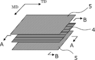
- FIG. 2 is a schematic perspective view showing an example of a laminated structure of a second porous layer / a first porous layer / a second porous layer.
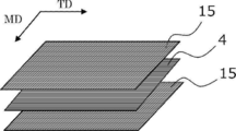
- FIG. 3 is a schematic perspective view showing a modified example of the laminated structure of FIG. Regarding the polyethylene microporous membrane of Example 1,
- FIG. 4 (a) is a scanning electron microscope (SEM) photograph when the surface layer is observed from the normal direction, and
- FIG. 4 (b) is polyethylene microporous along TD.
- SEM scanning electron microscope
- FIG. 4 (c) is a SEM photograph of the cut surface which cut
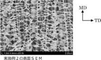
- FIG. 5 is an SEM photograph when the surface layer of the polyethylene microporous membrane of Example 2 was observed from the normal direction.
- FIG. 6A is a SEM photograph of the surface layer in the TD cross section
- FIG. 6B is a SEM photograph of the central layer in the TD cross section
- FIG. 6C is MD.
- the SEM photograph of the surface layer in a cross section is shown
- FIG.6 (d) is a SEM photograph of the center layer in MD cross section.
- FIG. 7 (a) is an SEM photograph when the surface layer is observed from the normal direction
- FIGS. 7 (b) and 7 (c) show each layer of the polyethylene microporous membrane. It is a SEM photograph.
- the numerical range indicated by using “to” indicates the range including the numerical values before and after “to” as the minimum value and the maximum value, respectively.
- the upper limit value or the lower limit value described in a certain numerical range may be replaced with the upper limit value or the lower limit value of another stepwise described numerical range.
- the upper limit value or the lower limit value described in a certain numerical range may be replaced with the values shown in the examples.
- machine direction means the lengthwise direction (that is, the conveying direction) of the polyolefin microporous membrane produced in a long shape
- width direction means the polyolefin microporous membrane. Means the direction orthogonal to the machine direction of the membrane.
- TD the "width direction”
- MD the "machine direction”
- the upper limit or the lower limit described in one numerical range may be replaced with the upper limit or the lower limit of the numerical range described in other stages. Good. Further, in the numerical range described in the present specification, the upper limit value or the lower limit value of the numerical range may be replaced with the value shown in the examples. Moreover, in this indication, “mass%” and “weight%” are synonymous, and “mass part” and “weight part” are synonymous. Furthermore, in the present disclosure, a combination of two or more preferable aspects is a more preferable aspect. In the present disclosure, the amount of each component in the composition or layer refers to the total amount of the plurality of substances present in the composition, unless a plurality of substances corresponding to each component are present in the composition, unless otherwise specified. Means
- process is included in this term as long as the intended purpose of the process is achieved, not only when it is an independent process but also when it cannot be clearly distinguished from other processes.
- the molecular weight when there is a molecular weight distribution represents the weight average molecular weight (Mw), unless otherwise specified.
- the polyolefin microporous membrane of the present disclosure has a structure that includes a polyolefin, a first rod-shaped crystal that extends in one direction, and a plurality of first plate-shaped crystals that are arranged in a separated state and that intersect with the first rod-shaped crystal.
- a first porous layer having, a second rod-shaped crystal containing a polyolefin and extending in the other direction intersecting with the one direction, and a plurality of second plate-like crystals arranged in a separated state and intersecting with the second rod-shaped crystal.
- the polyolefin microporous membrane of the present disclosure may have a plurality of first porous layers and a plurality of second porous layers, respectively. In addition to the first porous layer and the second porous layer, other You may have a layer of.
- the microporous membrane, the fibrillar polyolefin is connected to each other to form a three-dimensional network structure, has a plurality of micropores inside, a structure in which a plurality of micropores are connected to each other.
- it means a film in which gas or liquid can pass from one surface to the other surface.
- a biaxially stretched polyolefin microporous film is known as a film used for applications such as a liquid filter, but generally, when applied to remove gel-like foreign matter, the filter causes clogging.
- the filter causes clogging.
- a plurality of porous layers having a specific structure including a rod-shaped crystal and a plurality of plate-shaped crystals spaced apart by connecting with the rod-shaped crystal are stacked, and a plurality of porous layers are formed in each layer.
- the rod-like crystals are arranged so that their axial directions intersect with each other. As a result, it becomes possible to provide a polyolefin microporous membrane that has excellent gel-like foreign matter removal performance and is less likely to be clogged with foreign matter.
- the polyolefin microporous membrane of the present disclosure includes at least a first porous layer and a second porous layer, and has a laminated structure of two or more layers.
- the porous layer is a layer that has a plurality of pores inside and has a structure in which adjacent pores are connected to each other, and allows gas or liquid to pass from one surface to the other surface.
- the polyolefin microporous membrane of the present disclosure may have a laminated structure having two or more layers of at least one of the first porous layer and the second porous layer, and each has two or more layers of the first porous layer and the second porous layer. It may have a laminated structure, or may have a laminated structure in which one of the first porous layer and the second porous layer has an odd number layer and the other has an even number layer, for example, the following laminated structure.
- Second porous layer / first porous layer / second porous layer a) First porous layer / second porous layer b) Second porous layer / first porous layer / second porous layer c) Second porous layer / first porous layer / second porous layer Layer / first porous layer / second porous layer Among them, as shown in b) above, at least the second porous layer disposed on both surfaces of the first porous layer and the first porous layer, respectively.
- An embodiment having a laminated structure including layers is preferable.
- the porous layer in the present disclosure will be described by taking as an example the case of having the laminated structure of the above aspect a).
- the first porous layer is a layer having a structure including a first rod-shaped crystal extending in one direction and a plurality of first plate-shaped crystals arranged in a separated state and intersecting with the first rod-shaped crystal.
- the second porous layer is a second rod-shaped crystal that extends in the other direction that intersects with one direction in the first porous layer, and a plurality of second rod-shaped crystals that are arranged in a separated state and that intersect with the second rod-shaped crystal. It is a layer having a structure including plate crystals.
- the first porous layer and the second porous layer each include a rod-shaped crystal and a plurality of plate-shaped crystals, and the axial direction of the rod-shaped crystal in the first porous layer and the rod-shaped crystal in the second porous layer
- the axial direction and the axial direction intersect with each other. That is, the first porous layer and the second porous layer may be the same layer or different layers in terms of composition and structure, but at least a combination of a plurality of porous layers in which rod-shaped crystals are not in parallel relationship with each other is used.
- a structure that includes a first rod-shaped crystal that extends in one direction and a plurality of first plate-shaped crystals that are arranged in a separated state and intersect with the first rod-shaped crystal (hereinafter, may be referred to as a specific structure. ) Will be described with reference to FIG. 1
- the structure 1 shown in FIG. 1 has a first rod-shaped crystal 2 that is a rod-shaped crystal in which polyolefin molecules are arranged in one direction, that is, a uniaxial direction, and intersects with the first rod-shaped crystal 2, that is, skewered by the first rod-shaped crystal 2.
- the structure has the first plate-like crystal 3 which is a plurality of plate-like crystals connected to the first rod-like crystal.
- a plurality of plate-like crystals are juxtaposed in a state of being separated from each other along the axial direction of the rod-like crystals (first rod-like crystals) (intermittent arrangement state). ..
- a shish-kebab structure may be used.
- the shish kebab structure 1 is a structure that includes extended chain crystals that are rod-shaped crystals with one direction as an axis, and a plurality of folded chain crystals that are arranged side by side and intersect with the extended chain crystals in a separated state. Specifically, as shown in FIG.
- an extended-chain crystal extended-chain crystal; a so-called shish fibrous crystal
- a folded-chain crystal a so-called kebab crystal
- shishi a so-called kebab crystal
- the extended chain crystal in the shish kebab structure is one in which the molecular chain is stretched and oriented in the stretching direction by stretching, and the average distance between rod-shaped crystals represented by the extended chain crystal (interaxial distance of rod-shaped crystals) is Although not particularly limited, it is preferably, for example, 0.5 ⁇ m to 20 ⁇ m.
- extended chain crystals may be connected to each other via a folded chain crystal expanding in the axial direction, as shown in FIG.
- a plate crystal represented by a folded chain crystal in the shish kebab structure is a plate-like or block-like crystal part having two front and back surfaces in which lamella crystals are grown around an extended chain crystal that is stretched and oriented in the stretching direction.
- the shape may be flat, scale-like, or the like. However, the shape is not limited to these as long as it has two surfaces on the front and back sides.
- the average distance between plate-like crystals typified by folded chain crystals (distance between center thicknesses of plate-like crystals) arranged apart from each other along the axial direction of rod-like crystals is not particularly limited, but may be, for example, 0. It is preferably from 0.5 ⁇ m to 20 ⁇ m.
- the average value of the angles formed by the rod-shaped crystals represented by the extended chain crystals and the plate-shaped crystals represented by the folded chain crystals is preferably, for example, 30 ° to 150 °, more preferably 70 ° to 110. °.
- the angle formed by the rod-shaped crystal and the plate-shaped crystal refers to the angle formed by the axial direction of the rod-shaped crystal and the plane direction of the plane of the plate-shaped crystal.
- the “structure including a first rod-shaped crystal that extends in one direction and a plurality of first plate-shaped crystals that are arranged in a separated state and intersect with the first rod-shaped crystal” in the first porous layer has been described.
- the second porous layer “a structure including a second rod-shaped crystal extending in the other direction intersecting with one direction, and a plurality of second plate-shaped crystals arranged in a separated state and intersecting with the second rod-shaped crystal”
- the second rod-shaped crystal and the second plate-shaped crystal are the same as the first rod-shaped crystal and the first plate-shaped crystal, respectively, except that the arrangement angle of the rod-shaped crystal arranged in each porous layer is different.
- a porous structure of a polyolefin microporous membrane is formed by arranging a plurality of polyolefin units having a structure represented by a shish kebab structure.
- FIG. 2 is a schematic perspective view showing an example of a laminated structure of the second porous layer / the first porous layer / the second porous layer shown in the above aspect b), and FIG. 3 is the above aspect b). It is a schematic perspective view which shows the modification of.
- the polyolefin microporous membrane shown in FIG. 2 has a central layer (first porosity) having a shish kebab structure including extended chain crystals (first rod-shaped crystals) extending along the width direction (TD) orthogonal to the machine direction (MD).
- Layer) 4 and a surface layer (second porous layer) 5 which is provided on both surfaces of the central layer and has a shish-kebab structure including extended chain crystals (second rod-shaped crystals) extending along MD. It has a three-layer structure.
- the extended chain crystal that is the first rod-shaped crystal in the central layer 4 has a plurality of folded chain crystals (first plate-shaped crystals) grown in a form skewed by the extended chain crystal 2 as shown in FIG.
- the second rod-shaped crystal that is the extended chain crystal in the surface layer 5 also has a plurality of folded chain crystals (second plate-shaped crystal) grown in a form skewered by the extended chain crystal 2 as shown in FIG. ) 3 is connected (crossed).
- the polyolefin microporous membrane shown in FIG. 3 has a central layer (first porous layer) having a shish-kebab structure including extended chain crystals (first rod-shaped crystals) extending along the width direction (TD) orthogonal to the machine direction (MD). (Layer) 4 and the first shish-kebab structure including the first extended chain crystal (second rod-shaped crystal), which is provided on both surfaces of the central layer and (1) extends along MD, and (2) TD.
- a surface layer (second porous layer) 15 having a second shish-kebab structure including a second extended chain crystal (second rod-shaped crystal) extending along is formed into a three-layer structure.
- the extended chain crystal that is the first rod-shaped crystal in the central layer 4
- a plurality of folded chain crystals (grooved in a form skewered by the extended chain crystal 2 as in the polyolefin microporous film shown in FIG.
- the first plate crystals 3 are connected (crossed).
- the first extended chain crystals and the second extended chain crystals in the surface layer 15 intersect with each other and grow in a form skewed by the extended chain crystals 2 as shown in FIG.
- a plurality of folded chain crystals (second plate crystals) 3 are combined (crossed).
- a polyolefin microporous membrane having a structure such as the three-layer structure as described above, that is, a rod-shaped crystal and a structure including a plurality of plate-shaped crystals that are arranged in a separated state and intersect with the rod-shaped crystal is performed by, for example, stretching.
- the method for example, the stretching direction such as stretching in only one of MD and TD, the stretching ratio, etc.
- the type of solvent used when preparing the polyolefin solution, the heating temperature, and other conditions are selected according to the target layer structure. It can be done by For example, when stretching is performed, orientation can be achieved in the stretching direction.
- the extended chain crystal is “along the width direction” means that the axial direction of the extended chain crystal is ⁇ 30 ° to 30 ° with respect to the width direction (TD) of the polyolefin microporous film. Means within the range. Further, the fact that the extended chain crystal is “along the machine direction” means that the axial direction of the extended chain crystal is within the range of ⁇ 30 ° to 30 ° with respect to the machine direction (MD) of the polyolefin microporous film. Means that.
- the thickness of each layer can be in the following ranges:
- the thickness of the central layer is preferably 3 ⁇ m to 160 ⁇ m.
- the thickness of the surface layer per one surface is preferably 1 ⁇ m to 20 ⁇ m.
- the structure (for example, shish kebab structure) in the porous layer can be confirmed by a scanning electron microscope (SEM).
- SEM scanning electron microscope
- the layer structure of the porous layer in the polyolefin microporous membrane was obtained by cutting out a sample piece so that the machine direction (MD) and the width direction (TD) can be seen from the polyolefin microporous membrane produced in a long shape, and the SEM of the sample piece. The crystal structure can be confirmed by observing the photograph.
- Each of the first porous layer and the second porous layer contains at least one kind of polyolefin.
- the polyolefin include homopolymers of monomers such as ethylene, propylene, butylene, and methylpentene (polyethylene, polypropylene, polybutylene, polymethylpentene, etc.), or two or more monomers selected from the above monomers and the like. Or a mixture of one or more selected from the above homopolymers and copolymers. Of these, polyethylene is preferable.
- polyethylene high density polyethylene, a mixture of high density polyethylene and ultra high molecular weight polyethylene, etc. are suitable.
- polyethylene and a component other than polyethylene may be used in combination.
- components other than polyethylene include polypropylene, polybutylene, polymethylpentene, and copolymers of polypropylene and polyethylene.
- a plurality of polyolefins having different properties as polyolefins may be used. That is, a plurality of polyolefins having a poor degree of mutual compatibility and a combination of polymerization degrees or branching properties, in other words, a plurality of polyolefins having different crystallinity, stretchability and molecular orientation may be combined.
- the polyolefin composition contains 1% by mass or more of high molecular weight polyethylene having a weight average molecular weight of 1,000,000 to 6,000,000.
- high molecular weight polyethylene having a weight average molecular weight of 1,000,000 to 6,000,000
- low-molecular-weight polyethylene having a weight-average molecular weight of 200,000 or more and less than 1,000,000 are mixed in terms of easily forming a laminated structure having a shish-kebab structure.
- Compositions are preferred.
- the weight average molecular weight of the high molecular weight polyethylene As a lower limit of the weight average molecular weight of the high molecular weight polyethylene, 2,000,000 or more is more preferable, and 3,000,000 or more is further preferable. In this respect, by mixing an appropriate amount of two or more kinds of polyethylene, there is an effect of forming a network network structure associated with fibrillation at the time of stretching and increasing the void generation rate.
- the compounding ratio (hPE: lPE) of high molecular weight polyethylene (hPE) and low molecular weight polyethylene (lPE) is preferably 1:99 to 70:30 in terms of mass ratio.
- the low molecular weight polyethylene high density polyethylene having a density of 0.92 g / cm 3 to 0.96 g / cm 3 is preferable.
- the weight average molecular weight was determined by dissolving a sample of a polyolefin microporous membrane in o-dichlorobenzene with heating and using GPC (Alliance GPC 2000 type manufactured by Waters, column; GMH6-HT and GMH6-HTL) at a column temperature of 135 ° C. It can be obtained by measuring at a flow rate of 1.0 mL / min.
- GPC Alliance GPC 2000 type manufactured by Waters, column; GMH6-HT and GMH6-HTL
- the content of polyolefin in each porous layer of the microporous polyolefin membrane is preferably 90% by mass or more based on the total mass of each porous layer.
- each porous layer may contain an additive such as an organic or inorganic filler and a surfactant as a component other than the polyolefin as long as the effect of the present disclosure is not significantly impaired.
- the polyolefin microporous membrane of the present disclosure preferably has an average flow pore size of 20 nm to 300 nm.
- the polyolefin microporous membrane of the present disclosure has an average flow pore diameter in the above range in addition to the structure of the above-mentioned porous layer, is excellent in removing performance of gel-like foreign matter, and more effectively causes clogging by foreign matter. It can be suppressed.
- the average flow pore size is more preferably 30 nm or more, further preferably 40 nm or more, further preferably 50 nm or more, particularly preferably 60 nm or more.
- the average flow pore size is 300 nm or less, it is easy to maintain good performance of removing gel-like foreign matter.
- the average flow pore size is more preferably 290 nm or less, further preferably 280 nm or less, further preferably 270 nm or less, and particularly preferably 200 nm or less. The method of measuring the average flow pore size is as described in the section of Examples below.
- the method for adjusting the average flow pore diameter of the porous layer to the above range is not particularly limited, but, for example, the composition of the polyolefin, the concentration of the polyolefin in the raw material for forming the porous layer, the plurality of raw materials for forming the porous layer Mixing ratio when mixing solvents, heating temperature for squeezing out the solvent inside the sheet extruded into a sheet, extrusion pressure, heating time, stretching ratio, heat treatment (heat setting) temperature after stretching, extraction solvent
- a method of appropriately adjusting the immersion time, the annealing treatment temperature, the treatment time and the like can be mentioned.
- the ratio of the tensile strength in the machine direction (MD) to the tensile strength in the width direction (TD) is preferably 0.10 or more and 0.99 or less. ..
- the ratio (S MD / S TD ) of 0.99 or less is preferable in that the gel collection rate is further improved. The reason for this is not clear, but it is speculated that the ratio (S MD / S TD ) reflects the structure of the porous layer. That is, when the strength of TD is higher than that of MD, it is presumed that pores effective for gel collection are formed.
- the ratio (S MD / S TD ) is more preferably 0.94 or less.
- the ratio (S MD / S TD ) is 0.1 or more, the ratio between the MD tensile strength and the TD tensile strength is well balanced, and as a result, clogging is less likely to occur and the gel collection rate is good. It is estimated that From this point of view, the ratio (S MD / S TD ) is more preferably 0.2 or more, still more preferably 0.3 or more.
- the method for measuring the ratio (S MD / S TD ) is as described in the section of Examples below.
- the flow rate when ethanol is circulated in the thickness direction is 10 ml / min / cm 2 to 300 ml / min / cm 2 when converted under a pressure of 1 MPa. preferable.
- the flow rate of ethanol of the polyolefin microporous membrane is 10 ml / min / cm 2 or more, not only the water permeability of the liquid to be treated is easily obtained, but also stability during liquid passage (for example, to maintain a constant liquid passage amount) The stability of the power load and the stability of the liquid flow rate under a constant liquid pressure (constant power load) are easily obtained for a long period of time.
- the ethanol flow rate is more preferably 15 ml / min / cm 2 or more.
- the ethanol flow rate is 300 ml / min / cm 2 or less, it becomes easy to highly collect the gel-like foreign matter.
- the ethanol flow rate is more preferably 250 ml / min / cm 2 or less, further preferably 200 ml / min / cm 2 or less, and particularly preferably 100 ml / min / cm 2 or less.
- the liquid permeation performance can be evaluated using the liquid permeation amount (Vs) obtained from the following equation from the ethanol flow rate as an index, and the details of the calculation method are as described in the section of Examples described later.
- Permeation rate (Vs) V / (Tl ⁇ S) ...
- V Amount of ethanol [ml]
- Tl Permeation time of all ethanol [min]
- S Liquid permeation area of the liquid permeation cell [cm 2 ]
- the polyolefin microporous membrane of the present disclosure preferably has a thickness of 5 ⁇ m to 200 ⁇ m.
- the film thickness of the polyolefin microporous film is 5 ⁇ m or more, good mechanical strength can be easily obtained, and handling property when processing the polyolefin microporous film and durability in long-term use when processed into, for example, a filter cartridge. Is easy to obtain.
- a thicker layer is advantageous. From this viewpoint, the thickness of the microporous polyolefin membrane is more preferably 10 ⁇ m or more, further preferably 15 ⁇ m or more, and particularly preferably 20 ⁇ m or more.
- the thickness of the microporous polyolefin membrane is 200 ⁇ m or less, not only is it easy to obtain good liquid permeation performance with a single membrane, but also when it is processed into, for example, a filter cartridge of a predetermined size, a larger filtration area is obtained. Easy to obtain.
- the flow rate design and structure design of the filter when processing the microporous polyolefin membrane can be easily performed.
- the thickness of the polyolefin microporous film is more preferably 180 ⁇ m or less, further preferably 150 ⁇ m or less, further preferably 100 ⁇ m or less, and particularly preferably 80 ⁇ m or less. The method of measuring the thickness is as described in the section of Examples below.
- the polyolefin microporous membrane of the present disclosure preferably has a porosity of 55% to 85%.
- the porosity of the polyolefin microporous membrane is 55% or more, the liquid permeation performance becomes good and clogging hardly occurs. From this viewpoint, the porosity is more preferably 60% or more.
- the porosity is 85% or less, the mechanical strength of the polyolefin microporous film becomes good and the handling property also improves. In addition, the ability to collect gel-like foreign matter is also improved. From this viewpoint, the porosity is more preferably 80% or less, further preferably 75% or less.
- the polyolefin microporous membrane of the present disclosure preferably has a Gurley value of 0.1 sec / 100 ml to 200 sec / 100 ml.
- the Gurley value of the polyolefin microporous film is 0.1 sec / 100 ml or more, the ability to collect gel-like foreign matter becomes good.
- the Gurley value is more preferably 10 seconds / 100 ml or more.
- the Gurley value is 200 seconds / 100 ml or less, the liquid permeability of the liquid to be treated becomes good. It is also preferable from the viewpoint of preventing clogging. From this viewpoint, the Gurley value is more preferably 150 seconds / 100 ml or less, further preferably 100 seconds / 100 ml or less.
- the method for measuring the Gurley value is as described in the section of Examples described later.
- the polyolefin microporous membrane of the present disclosure can be used as a substrate for liquid filters.
- the polyolefin microporous membrane may be used as a liquid filter substrate that has been processed to impart an affinity with a chemical liquid. Further, the microporous polyolefin membrane may be processed into a cartridge shape and used as a substrate for a liquid filter.
- a porous base material such as polytetrafluoroethylene
- a porous base material such as polytetrafluoroethylene
- the polyolefin microporous membrane of the present disclosure when used as a substrate for a liquid filter, compared with a conventional porous substrate such as polytetrafluoroethylene, it has a good affinity with a chemical liquid, and therefore, for example, a filter and a chemical liquid There is an advantage that processing for giving affinity is facilitated.
- the filter cartridge is loaded into the filter housing and the filtration of the chemical liquid is started, when the chemical liquid is filled in the filter, air is less likely to build up in the filter cartridge, which improves the filtration yield of the chemical liquid.
- the content of halogen element in polyolefin such as polyethylene itself is low, it is easy to handle the used filter cartridge, and it is expected that the environmental load can be reduced.
- the polyolefin microporous membrane of the present disclosure can be used for applications other than liquid filter substrates, and can be expected to be applied to applications such as gas filters, gas-liquid separation membranes, and blood cell separation membranes. ..
- the polyolefin microporous membrane of the present disclosure can be suitably manufactured by the method shown below. That is, it is preferable to use a manufacturing method in which the following steps (I) to (IV) are sequentially performed.
- a solution containing the polyolefin composition and a solvent is prepared, but it is preferable to prepare a solution containing a nonvolatile solvent having a boiling point of 210 ° C. or higher at least at atmospheric pressure.
- the non-volatile solvent used for preparing the present solution include liquid paraffin, paraffin oil, mineral oil, castor oil and the like, and liquid paraffin is preferable.
- the volatile solvent is not particularly limited as long as it can swell or dissolve the polyolefin well, and liquid solvents such as tetralin, ethylene glycol, decalin, toluene, xylene, diethyltriamine, ethylenediamine, dimethylsulfoxide, and hexane. preferable.
- the volatile solvents may be used alone or in combination of two or more. Among them, the volatile solvent is preferably decalin or xylene.
- the concentration of the polyolefin composition is preferably 10% by mass to 40% by mass, more preferably 13% by mass to 25% by mass.
- the concentration of the polyolefin composition is 10% by mass or more, the mechanical strength can be further increased, so that the handling property becomes better, and further, the polyolefin microporous film becomes easier to form. Further, when the concentration of the polyolefin composition is 40% by mass or less, it tends to easily form pores.
- the solution prepared in the step (I) is melt-kneaded, and the obtained melt-kneaded product is extruded from a die and cooled and solidified to obtain a gel-like molded product.
- the extrudate is extruded from a die within a temperature range of the melting point to (melting point + 65 ° C.) of the polyolefin composition to obtain an extrudate, and the extrudate obtained is cooled to obtain a gel-like molded product.
- the molded product is preferably a molded product shaped into a sheet.
- the cooling may be quenching in an aqueous solution or an organic solvent, or may be casting on a cooled metal roll.
- the cooling temperature is preferably 5 ° C to 40 ° C. It is preferable to prepare a gel-like sheet while providing a water flow on the surface layer of the water bath so that the solvent released from the gelled sheet in the water bath and floating on the water surface does not adhere to the sheet again.
- the step (III) is a step of stretching the gel-like molded product in one of the machine direction and the width direction.
- the stretching in the step (III) is preferably uniaxial stretching in the machine direction (MD) or the width direction (TD) orthogonal to MD, and more preferably uniaxial stretching in TD without stretching in MD. ..
- the stretching ratio is preferably 3 to 50 times, more preferably 4 to 20 times. When the stretching ratio is 3 times or more, not only the polyolefin microporous film is more easily formed, but also the structure represented by the shish-kebab structure as described above is easily formed.
- Stretching is preferably performed with the solvent left in a suitable state.
- the stretching temperature is preferably 80 ° C to 140 ° C, more preferably 100 ° C to 130 ° C.
- the heat setting temperature is preferably 110 ° C. to 145 ° C., and 120 ° C. to 140 ° C., from the viewpoint of controlling the liquid permeation performance of the polyolefin microporous membrane and the removal performance of gelled foreign matter that is one of the filtration targets. C is more preferred. If the heat setting temperature is 145 ° C. or lower, the removal performance of the filtration object of the polyolefin microporous membrane will be better, and if the heat setting temperature is 110 ° C. or higher, it is suitable for maintaining better liquid permeation performance. ing.
- Step (IV) is a step of extracting and washing the solvent from the inside of the stretched intermediate molded product.
- step (IV) in order to extract the solvent from the inside of the stretched intermediate molded product (stretched film), it is preferable to wash with a solvent of a halogenated hydrocarbon such as methylene chloride or a hydrocarbon such as hexane.
- a solvent of a halogenated hydrocarbon such as methylene chloride or a hydrocarbon such as hexane.
- the tank is divided into several stages, the cleaning solvent is poured from the downstream side of the polyolefin microporous membrane transportation step, and the cleaning solvent is flowed toward the upstream side of the step transportation,
- the purity of the washing solvent in the downstream tank is preferably higher than that in the upstream layer.
- heat setting may be performed by annealing depending on the performance required for the microporous polyolefin membrane.
- the annealing treatment is preferably performed at 50 ° C. to 150 ° C., more preferably 50 ° C. to 140 ° C., from the viewpoint of transportability in the process.
- microporous polyolefin membrane having both excellent liquid permeation performance under high pressure and excellent performance of removing an object to be filtered even though it is a thin film.
- the liquid filter according to the present disclosure includes the polyolefin microporous membrane according to the present disclosure described above, and can be used after being processed into a shape such as a cartridge as necessary. Further, the liquid filter may be subjected to a processing that imparts an affinity with the chemical liquid, if necessary.
- the liquid filter allows a liquid to be treated containing or possibly containing organic particles, inorganic particles, gel-like substances, etc. to pass through and remove the particles and gel-like substances from the liquid to be treated. Further, the liquid filter can be used, for example, in a semiconductor manufacturing process, a display manufacturing process, a polishing process, and the like.
- the polyolefin microporous membrane of the present disclosure has a purpose other than the above-described liquid filter, for example, for the purpose of separation, purification, concentration, fractionation, detection, etc. of a substance dispersed or dissolved in a fluid (that is, gas or liquid). May be used. Specific examples include various filters used for water purification, sterilization, desalination, seawater desalination, artificial dialysis, pharmaceutical manufacturing, food manufacturing, in-vitro diagnostic equipment, gas-liquid separation, etc .; chromatography carriers; and the like.
- Test strength Using a tensile tester (RTE-1210 manufactured by Orientec Co., Ltd.), a test piece (width 15 mm, length 50 mm) obtained by cutting a polyethylene microporous film into a strip shape was subjected to MD and TD at a speed of 200 mm / min. Each was pulled and the tensile strength was measured. Based on the measured values, the ratio of the tensile strength in the machine direction to the tensile strength in the width direction was obtained.
- RTE-1210 manufactured by Orientec Co., Ltd.
- Gurley value The Gurley value (second / 100 ml) of the polyethylene microporous membrane having an area of 642 mm 2 was measured by a method based on Japanese Industrial Standard (JIS) P8117.
- a palm porometer porous material automatic pore size distribution measurement system [Capillary Flow Porometer] manufactured by PMI Co., Ltd. is used to apply a pore size distribution measurement test method [half-dry method (ASTM E1294-89)] to determine the average flow pore size. It was measured.
- the test solution used was perfluoropolyester (trade name: Galwick) (interfacial tension value: 15.9 dyne / cm), the measurement temperature was 25 ° C., and the measurement pressure was changed in the range of 0 kPa to 1500 kPa. ..
- the thickness of the polyethylene microporous film was measured at 20 points, and the measured values were averaged.
- the contact terminal was a cylindrical one having a bottom surface of 0.5 cm in diameter, and the measurement pressure was 0.1 N.
- the polyethylene microporous membrane was cut into 10 cm ⁇ 10 cm to prepare a sample piece, the mass of the sample piece was measured, and the measured mass was divided by the area to determine the basis weight.
- ⁇ (%) ⁇ 1-Ws / (ds ⁇ t) ⁇ ⁇ 100 Ws: basis weight of microporous polyolefin membrane (g / m 2 ) ds: true density of polyolefin (g / cm 3 ). t: thickness of the microporous polyolefin membrane ( ⁇ m)
- the polyethylene microporous membrane was previously immersed in ethanol and dried at room temperature. This polyethylene microporous membrane was set in a stainless liquid permeation cell (liquid permeation area Scm 2 ) having a diameter of 47 mm. After wetting the polyethylene microporous membrane on the liquid permeable cell with a small amount (0.5 ml) of ethanol, the amount V of ethanol (100 ml) previously measured at a differential pressure of 90 kPa was passed through, and the total amount of ethanol was passed through. The time Tl (min) required for was measured.
- a soybean milk (brand: Kikkoman tasty unadjusted soybean milk) was diluted with water 400000 times to prepare a gel-like liquid.
- the polyethylene microporous membrane was set in a stainless liquid-permeable cell having a diameter of 47 mm.
- the polyethylene microporous membrane on the liquid-permeable cell was wetted with a small amount (0.5 ml) of ethanol, and then water (20 ml) preliminarily measured at a differential pressure of 90 kPa was permeated.
- the gel-like liquid (20 ml) was repeatedly permeated, and the time T1 (sec) required for permeation of the total amount of gel-like liquid for the first time and the permeation of the total amount of gel-like liquid for the fifth time
- the required time T2 (sec) was measured. From the time required for the first permeation and the time required for the fifth permeation, the increase rate ⁇ T% of the permeation time due to gel collection was calculated from the following formula, and the gel foreign matter collection performance and clogging It was used as a standard.
- Example 1 A polyethylene composition was used in which 10 parts by mass of high molecular weight polyethylene (PE1) having a weight average molecular weight of 4.6 million and 7 parts by mass of low molecular weight polyethylene (PE2) having a weight average molecular weight of 560,000 were mixed.
- the polyethylene composition was mixed with 83 parts by mass of liquid paraffin prepared in advance so that the total concentration of the polyethylene resin was 17% by mass to prepare a polyethylene solution.
- This polyethylene solution is extruded into a sheet form from a die at a temperature of 150 ° C, the extruded sheet is cooled in a water bath of 19 ° C, and the mixed solvent is released from the gelled sheet in the water bath and floats on the water surface.
- a gel-like sheet (base tape) was prepared while preventing the particles from reattaching to the sheet.
- the produced base tape was conveyed while applying a pressure of 0.06 MPa on a roller heated to 90 ° C., and a part of liquid paraffin was removed from the inside of the base tape. At this time, the base tape was not stretched in the transport direction (MD). Then, the base tape was stretched at a temperature of 105 ° C. in the width direction (TD) at a draw ratio of 9 times (transverse stretching), and immediately after transverse stretching, heat treatment (heat setting) was performed at 136 ° C.
- the heat-fixed base tape was continuously immersed in a methylene chloride bath divided into two tanks for 200 seconds each to extract liquid paraffin.
- the purity of the cleaning solvent in each tank is (low) first layer ⁇ second tank (high). is there.
- methylene chloride was dried and removed at 40 ° C., and annealed while being conveyed on a roller heated to 120 ° C.
- a filter substrate made of a polyethylene microporous membrane polyolefin microporous membrane
- the structure of the polyethylene microporous membrane obtained as described above was confirmed by the following method. Specifically, the obtained polyethylene microporous membrane was observed by SEM as described above, and the crystal structure of the polymer in the membrane and the directions of MD and TD were analyzed from the observation photograph. As a result, the layer structure of the polyethylene microporous membrane was a laminated structure composed of three layers, and as shown in FIG. 3, on both surfaces of the central layer (first porous layer), along (1) MD, respectively. A surface layer (second porous layer) having a first shish-kebab structure containing a first extended chain crystal and a second shish-kebab structure containing a second extended chain crystal (2) extending along TD. I confirmed that I had it.
- FIG. 4A is a SEM photograph when the surface layer is observed from the normal direction.
- the surface layer has extended chain crystals that are rod-shaped crystals extending in both MD and TD and oriented so as to intersect each other. This point was similarly observed on both one side and the other side of the polyethylene microporous membrane.
- the extended chain crystal has a plurality of folded chain crystals that are plate-like crystals that intersect the extended chain crystal so as to be skewered, are separated from each other, and are bonded to the extended chain crystal.
- FIG. 4B is a SEM photograph of a cut surface obtained by cutting the polyethylene microporous film along the TD. Extended chain crystals extending along TD were observed in the surface layer, and extended chain crystals were also observed in the center layer.
- FIG. 4C is a SEM photograph of a cut surface obtained by cutting the polyethylene microporous film along the MD. No extended chain crystals were found in the central layer, and only plate-like crystals (folded chain crystals) intersecting with extended chain crystals were seen, but extended chain crystals extending along MD were observed in the surface layer. Admitted.
- Example 2 For a liquid filter comprising a polyethylene microporous membrane (polyolefin microporous membrane) in the same manner as in Example 1 except that the composition of the solution and the extrusion conditions were changed as shown in Table 1 below. A base material was obtained.
- the layer structure of the polyethylene microporous membrane obtained in Example 2 is a laminated structure composed of three layers, and as shown in FIG. 2, a central layer having a shish kebab structure including extended chain crystals extending along TD ( It was confirmed to have a first porous layer) and a surface layer (second porous layer) having a shish kebab structure provided on both surfaces of the central layer and having extended chain crystals extending along MD.
- Example 1 the film had a denser structure on the surface layer side in the film thickness direction, whereas the structure in the central portion was rougher than the surface layer.
- An SEM photograph of the surface layer of the polyethylene microporous membrane is shown in FIG. FIG. 5 is an SEM photograph when the surface layer is observed from the normal direction.
- the SEM photograph of each layer of the polyethylene microporous membrane is shown in FIG. 6A shows a SEM photograph of the surface layer and FIG. 6B shows a SEM photograph of the center layer of the cross section (cross section taken along the line AA of FIG. 2) obtained by cutting the polyethylene microporous membrane along the TD. Indicates. In the structure along the TD, as shown in FIG.
- FIG. 6A folded chain crystals that are plate-like crystals are mainly observed in the surface layer, and extended chain crystals that are rod-shaped crystals are mainly observed in the center layer. It was seen.
- FIG. 6C shows a SEM photograph of the surface layer
- FIG. 6D shows a SEM photograph of the central layer. Indicates.
- FIG. 6C elongated chain crystals that are rod-like crystals are mainly observed in the surface layer, and folded chain crystals that are plate-like crystals are mainly observed in the central layer. It was seen.
- a polyethylene composition was used in which 14 parts by mass of high molecular weight polyethylene (PE1) having a weight average molecular weight of 4.6 million and 11 parts by mass of low molecular weight polyethylene (PE2) having a weight average molecular weight of 560,000 were mixed.
- a polyethylene solution was prepared by mixing a polyethylene composition with 75 parts by mass of decalin (decahydronaphthalene) prepared in advance so that the total concentration of the polyethylene resin would be 25% by mass.
- This polyethylene solution was extruded into a sheet form from a die at a temperature of 154 ° C., and the extruded sheet was cooled in a water bath of 20 ° C. to prepare a gel-like sheet (base tape).
- the prepared base tape is pre-dried in a temperature atmosphere of 60 ° C. for 5 minutes and in a temperature atmosphere of 70 ° C. for 5 minutes, and then a magnification of 1.5 times in the transport direction (MD) of the base tape.
- MD transport direction
- the primary drawing was performed.
- main drying was performed for 5 minutes in a temperature atmosphere of 57 ° C. (the residual amount of the solvent in the base tape at this time was less than 1% by mass).
- the base tape is further stretched in MD at a temperature of 95 ° C. at a magnification of 6.0 times (longitudinal stretching) as a secondary stretching, and subsequently in the width direction (TD) at a temperature of 130 ° C. It was stretched at 9.0 times (horizontally stretched).
- heat treatment heat setting
- the heat-fixed base tape was continuously dipped in a methylene chloride bath divided into two tanks for 30 seconds each. Then, methylene chloride was removed by drying at 40 ° C.
- a liquid filter substrate made of a polyethylene microporous membrane for comparison was obtained.
- a polyethylene composition was used in which 3 parts by mass of high-molecular-weight polyethylene (PE1) having a weight-average molecular weight of 4.6 million and 14 parts by mass of low-molecular-weight polyethylene (PE2) having a weight-average molecular weight of 560,000 were mixed.
- PE1 high-molecular-weight polyethylene
- PE2 low-molecular-weight polyethylene
- a polyethylene composition and a mixed solvent of 51 parts by mass of liquid paraffin and 32 parts by mass of decalin (decahydronaphthalene) prepared in advance are mixed so that the total concentration of the polyethylene resin is 17% by mass, and a polyethylene solution is prepared.
- decalin decahydronaphthalene
- This polyethylene solution was extruded into a sheet form from a die at a temperature of 162 ° C., the extruded sheet was cooled in a water bath of 22 ° C., and the mixed solvent released from the gelled sheet in the water bath and floating on the water surface was removed.
- a gel-like sheet (base tape) was prepared while avoiding reattachment to the sheet.
- the produced base tape was dried under a temperature atmosphere of 60 ° C. for 5 minutes and under a temperature atmosphere of 95 ° C. for 5 minutes to remove decalin from the base tape. Subsequently, the base tape was conveyed on a roller heated to 90 ° C.
- the base tape was stretched (longitudinal) at a temperature of 90 ° C. at a magnification of 5.5 times in the transport direction (MD) of the base tape, and subsequently at a temperature of 106 ° C. in the width direction (TD). It was stretched 10 times (transverse stretching). Immediately after transverse stretching, heat treatment (heat setting) was performed at 140 ° C. Next, the heat-fixed base tape was continuously immersed in a methylene chloride bath divided into two tanks for 60 seconds each to extract liquid paraffin.
- the purity of the cleaning solvent is (low) first layer ⁇ second tank (high). Then, methylene chloride was dried and removed at 40 ° C., and annealed while being conveyed on a roller heated to 120 ° C. As described above, a liquid filter substrate made of a polyethylene microporous membrane for comparison was obtained.
- a polyethylene composition was used in which 10 parts by mass of a high-molecular-weight polyethylene (PE1) having a weight-average molecular weight of 4.6 million and 7 parts by mass of a low-molecular-weight polyethylene (PE2) having a weight-average molecular weight of 560,000 were mixed.
- the polyethylene composition was mixed with 83 parts by mass of liquid paraffin prepared in advance so that the total concentration of the polyethylene resin was 17% by mass to prepare a polyethylene solution.
- This polyethylene solution was extruded into a sheet form from a die at a temperature of 150 ° C., the extruded sheet was cooled in a water bath at 19 ° C., and the mixed solvent released from the gelled sheet in the water bath and floating on the water surface
- a gel-like sheet (base tape) was prepared while avoiding reattachment to the sheet.
- the prepared base tape is continuously immersed in a methylene chloride bath divided into two tanks for 200 seconds each without removing part of the liquid paraffin, transverse stretching and heat setting. And liquid paraffin was extracted.
- the purity of the cleaning solvent is (low) first layer ⁇ second tank (high).
- methylene chloride was dried and removed at 40 ° C., and annealed while being conveyed on a roller heated to 120 ° C. After that, the base tape was stretched in the width direction (TD) at a temperature of 105 ° C. at a draw ratio of 9 times (transverse stretching), and immediately thereafter, heat treatment (heat setting) was performed at 136 ° C.
- FIG. 7A is an SEM photograph when the surface layer is observed from the normal direction. SEM photographs of each layer of this polyethylene microporous membrane are shown in FIGS. 7 (b) and 7 (c).
- the polyethylene microporous membrane obtained in Comparative Example 5 had rod-like crystals extending branchwise in any direction, but did not have a structure in which the rod-like crystals were oriented in one direction. Further, as shown in FIGS.
- a plate in which rod-like crystals extending in an arbitrary direction in a branch shape are combined with the rod-like crystals so as to be skewered in both the surface layer and the central layer No state crystals, that is, crystals having two surfaces on the front and back were observed, and no shish kebab structure could be recognized.
- a plurality of porous layers having a specific structure including a rod-shaped crystal and a plurality of plate-shaped crystals that are spaced apart by connecting with the rod-shaped crystal are stacked, and the plurality of porous layers are formed into the rod-shaped crystal of each layer.
- the polyolefin microporous membrane of the example having a structure in which the axial directions intersect each other was excellent in the ability to remove gel-like foreign matter, and the occurrence of clogging due to foreign matter was suppressed to a small extent.
- the polyolefin microporous film of Comparative Example not only was the gel-like foreign matter removability low, but the foreign matter frequently clogged.
Landscapes
- Chemical & Material Sciences (AREA)
- Chemical Kinetics & Catalysis (AREA)
- Engineering & Computer Science (AREA)
- Polymers & Plastics (AREA)
- Health & Medical Sciences (AREA)
- Medicinal Chemistry (AREA)
- Materials Engineering (AREA)
- Organic Chemistry (AREA)
- Manufacturing & Machinery (AREA)
- Nanotechnology (AREA)
- Water Supply & Treatment (AREA)
- Separation Using Semi-Permeable Membranes (AREA)
- Laminated Bodies (AREA)
- Manufacture Of Porous Articles, And Recovery And Treatment Of Waste Products (AREA)
- Cell Separators (AREA)
Abstract
Un mode de réalisation de la présente invention est une membrane microporeuse en polyoléfine comprenant: une première couche poreuse contenant une polyoléfine et ayant une structure comprenant un premier cristal en forme de tige s'étendant dans une direction et une pluralité de premiers cristaux en forme de plaque disposés à intervalles les uns des autres et croisant le premier cristal en forme de tige; et une seconde couche poreuse contenant une polyoléfine et ayant une structure comprenant un second cristal en forme de tige s'étendant dans une autre direction croisant la première direction et une pluralité de seconds cristaux en forme de plaque disposés à intervalles les uns des autres et croisant le second cristal en forme de tige.
Priority Applications (3)
| Application Number | Priority Date | Filing Date | Title |
|---|---|---|---|
| US17/288,989 US20210402357A1 (en) | 2018-10-30 | 2019-10-29 | Polyolefin microporous membrane and liquid filter |
| KR1020217012028A KR102564259B1 (ko) | 2018-10-30 | 2019-10-29 | 폴리올레핀 미다공막 및 액체 필터 |
| CN201980069857.XA CN112912164B (zh) | 2018-10-30 | 2019-10-29 | 聚烯烃微多孔膜及液体过滤器 |
Applications Claiming Priority (2)
| Application Number | Priority Date | Filing Date | Title |
|---|---|---|---|
| JP2018-204441 | 2018-10-30 | ||
| JP2018204441A JP7152106B2 (ja) | 2018-10-30 | 2018-10-30 | ポリオレフィン微多孔膜及び液体フィルター |
Publications (1)
| Publication Number | Publication Date |
|---|---|
| WO2020090792A1 true WO2020090792A1 (fr) | 2020-05-07 |
Family
ID=70463262
Family Applications (1)
| Application Number | Title | Priority Date | Filing Date |
|---|---|---|---|
| PCT/JP2019/042303 WO2020090792A1 (fr) | 2018-10-30 | 2019-10-29 | Membrane microporeuse en polyoléfine et filtre à liquide |
Country Status (5)
| Country | Link |
|---|---|
| US (1) | US20210402357A1 (fr) |
| JP (1) | JP7152106B2 (fr) |
| KR (1) | KR102564259B1 (fr) |
| CN (1) | CN112912164B (fr) |
| WO (1) | WO2020090792A1 (fr) |
Families Citing this family (1)
| Publication number | Priority date | Publication date | Assignee | Title |
|---|---|---|---|---|
| JP6787464B2 (ja) * | 2018-10-12 | 2020-11-18 | 大日本印刷株式会社 | 化粧板及び該化粧板の製造方法 |
Citations (8)
| Publication number | Priority date | Publication date | Assignee | Title |
|---|---|---|---|---|
| JPH07246322A (ja) * | 1994-03-11 | 1995-09-26 | Mitsubishi Chem Corp | 改質ポリオレフィン多孔膜及びそれを用いた濾過フィルター |
| JP2005105198A (ja) * | 2003-10-01 | 2005-04-21 | Teijin Ltd | 多孔質シートおよびその製造方法 |
| JP2010053245A (ja) * | 2008-08-28 | 2010-03-11 | Teijin Ltd | ポリオレフィン微多孔膜 |
| JP2010202828A (ja) * | 2009-03-05 | 2010-09-16 | Asahi Kasei E-Materials Corp | ポリオレフィン製微多孔膜 |
| WO2012042716A1 (fr) * | 2010-09-30 | 2012-04-05 | パナソニック株式会社 | Séparateur destiné à une batterie secondaire à électrolyte non aqueux et batterie secondaire à électrolyte non aqueux utilisant ce séparateur |
| WO2014181760A1 (fr) * | 2013-05-07 | 2014-11-13 | 帝人株式会社 | Matériau de base pour filtre à liquide |
| US20170294636A1 (en) * | 2016-04-08 | 2017-10-12 | Daramic, Llc | Separators for enhanced flooded batteries, batteries, and related methods |
| JP2018516441A (ja) * | 2015-06-03 | 2018-06-21 | セルガード エルエルシー | 改良された低電気抵抗微多孔質バッテリセパレータ膜、セパレータ、電池、バッテリ及び関連する方法 |
Family Cites Families (7)
| Publication number | Priority date | Publication date | Assignee | Title |
|---|---|---|---|---|
| US5194154A (en) * | 1991-12-05 | 1993-03-16 | The Dow Chemical Company | Structure for filter or heat exchanger, composed of a fused single crystal acicular ceramic |
| US9457322B2 (en) * | 2009-04-13 | 2016-10-04 | Entegris, Inc. | Porous composite membrane |
| US20140094076A1 (en) * | 2011-06-16 | 2014-04-03 | James S. Mrozinski | Microporous Materials With Fibrillar Mesh Structure and Methods of Making and Using the Same |
| CN104769027B (zh) * | 2012-08-29 | 2019-11-05 | 国立大学法人群马大学 | 聚乙烯制多孔膜的制造方法及聚乙烯制多孔膜 |
| WO2015198948A1 (fr) * | 2014-06-25 | 2015-12-30 | 帝人株式会社 | Matériau de base pour filtre liquide, et procédé de fabrication de ce matériau |
| CN109997247B (zh) * | 2016-11-17 | 2022-03-11 | 香港科技大学 | 纳米多孔超高分子量聚乙烯薄膜 |
| JP6858618B2 (ja) * | 2017-03-30 | 2021-04-14 | 帝人株式会社 | 液体フィルター用基材 |
-
2018
- 2018-10-30 JP JP2018204441A patent/JP7152106B2/ja active Active
-
2019
- 2019-10-29 CN CN201980069857.XA patent/CN112912164B/zh active Active
- 2019-10-29 WO PCT/JP2019/042303 patent/WO2020090792A1/fr active Application Filing
- 2019-10-29 US US17/288,989 patent/US20210402357A1/en active Pending
- 2019-10-29 KR KR1020217012028A patent/KR102564259B1/ko active IP Right Grant
Patent Citations (8)
| Publication number | Priority date | Publication date | Assignee | Title |
|---|---|---|---|---|
| JPH07246322A (ja) * | 1994-03-11 | 1995-09-26 | Mitsubishi Chem Corp | 改質ポリオレフィン多孔膜及びそれを用いた濾過フィルター |
| JP2005105198A (ja) * | 2003-10-01 | 2005-04-21 | Teijin Ltd | 多孔質シートおよびその製造方法 |
| JP2010053245A (ja) * | 2008-08-28 | 2010-03-11 | Teijin Ltd | ポリオレフィン微多孔膜 |
| JP2010202828A (ja) * | 2009-03-05 | 2010-09-16 | Asahi Kasei E-Materials Corp | ポリオレフィン製微多孔膜 |
| WO2012042716A1 (fr) * | 2010-09-30 | 2012-04-05 | パナソニック株式会社 | Séparateur destiné à une batterie secondaire à électrolyte non aqueux et batterie secondaire à électrolyte non aqueux utilisant ce séparateur |
| WO2014181760A1 (fr) * | 2013-05-07 | 2014-11-13 | 帝人株式会社 | Matériau de base pour filtre à liquide |
| JP2018516441A (ja) * | 2015-06-03 | 2018-06-21 | セルガード エルエルシー | 改良された低電気抵抗微多孔質バッテリセパレータ膜、セパレータ、電池、バッテリ及び関連する方法 |
| US20170294636A1 (en) * | 2016-04-08 | 2017-10-12 | Daramic, Llc | Separators for enhanced flooded batteries, batteries, and related methods |
Also Published As
| Publication number | Publication date |
|---|---|
| US20210402357A1 (en) | 2021-12-30 |
| JP2020070337A (ja) | 2020-05-07 |
| KR102564259B1 (ko) | 2023-08-07 |
| KR20210060601A (ko) | 2021-05-26 |
| CN112912164A (zh) | 2021-06-04 |
| CN112912164B (zh) | 2023-01-10 |
| JP7152106B2 (ja) | 2022-10-12 |
Similar Documents
| Publication | Publication Date | Title |
|---|---|---|
| KR100530614B1 (ko) | 고투과성 폴리올레핀 미다공막의 제조방법 | |
| US8092581B2 (en) | Gas separation membrane | |
| EP1870430B1 (fr) | Film polyolefinique microporeux et son procede de production | |
| JPH0364334A (ja) | ポリオレフィン微多孔膜 | |
| EP1873194B1 (fr) | Procede de production d' un film microporeux polyolefinique et film microporeux | |
| KR20110096077A (ko) | 에틸렌-클로로트라이플루오로에틸렌 공중합체로부터의 미세다공성 재료 및 그의 제조 방법 | |
| WO2018168871A1 (fr) | Membrane microporeuse en polyoléfine | |
| JP2010024463A (ja) | ポリオレフィン微多孔膜の製造方法、および、電池用セパレータの製造方法 | |
| KR20200122428A (ko) | 액체 필터용 기재 | |
| WO2020090792A1 (fr) | Membrane microporeuse en polyoléfine et filtre à liquide | |
| KR102540711B1 (ko) | 액체 필터용 기재 | |
| KR20140073331A (ko) | 다공성 ptfe 분리막 및 그 제조방법 | |
| JP6996383B2 (ja) | ポリオレフィン微多孔膜の製造方法 | |
| WO2020022321A1 (fr) | Matériau de base pour des filtres liquide | |
| JP3009495B2 (ja) | ポリオレフィン微多孔膜及びその製造方法 | |
| JP2006111712A (ja) | ポリオレフィン微多孔膜 | |
| JP3967421B2 (ja) | ポリオレフィン微多孔膜の製造方法 | |
| JPH093228A (ja) | ポリオレフィン微多孔膜の製造方法 | |
| KR20160005738A (ko) | 액체 필터용 기재 | |
| KR20160006723A (ko) | 액체 필터용 기재 | |
| JPH11106533A (ja) | ポリオレフィン製多孔質膜 | |
| JP2022049164A (ja) | ポリオレフィン微多孔膜 | |
| JP2023135799A (ja) | ポリオレフィン微多孔膜および濾過フィルター | |
| JPH05156058A (ja) | ポリオレフィン微多孔膜の製造方法 | |
| JP2657434C (fr) |
Legal Events
| Date | Code | Title | Description |
|---|---|---|---|
| 121 | Ep: the epo has been informed by wipo that ep was designated in this application |
Ref document number: 19879084 Country of ref document: EP Kind code of ref document: A1 |
|
| ENP | Entry into the national phase |
Ref document number: 20217012028 Country of ref document: KR Kind code of ref document: A |
|
| NENP | Non-entry into the national phase |
Ref country code: DE |
|
| 122 | Ep: pct application non-entry in european phase |
Ref document number: 19879084 Country of ref document: EP Kind code of ref document: A1 |