WO2020090792A1 - Polyolefin microporous membrane and liquid filter - Google Patents
Polyolefin microporous membrane and liquid filter Download PDFInfo
- Publication number
- WO2020090792A1 WO2020090792A1 PCT/JP2019/042303 JP2019042303W WO2020090792A1 WO 2020090792 A1 WO2020090792 A1 WO 2020090792A1 JP 2019042303 W JP2019042303 W JP 2019042303W WO 2020090792 A1 WO2020090792 A1 WO 2020090792A1
- Authority
- WO
- WIPO (PCT)
- Prior art keywords
- polyolefin
- microporous membrane
- crystals
- porous layer
- rod
- Prior art date
Links
- 229920000098 polyolefin Polymers 0.000 title claims abstract description 143
- 239000012982 microporous membrane Substances 0.000 title claims abstract description 106
- 239000007788 liquid Substances 0.000 title claims description 79
- 239000013078 crystal Substances 0.000 claims abstract description 195
- LFQSCWFLJHTTHZ-UHFFFAOYSA-N Ethanol Chemical compound CCO LFQSCWFLJHTTHZ-UHFFFAOYSA-N 0.000 claims description 38
- 239000012528 membrane Substances 0.000 claims description 34
- 239000011148 porous material Substances 0.000 claims description 26
- 239000000758 substrate Substances 0.000 claims description 15
- 101100453790 Drosophila melanogaster Kebab gene Proteins 0.000 claims description 13
- 235000015231 kebab Nutrition 0.000 claims description 13
- 239000010410 layer Substances 0.000 description 143
- -1 polyethylene Polymers 0.000 description 89
- 239000004698 Polyethylene Substances 0.000 description 87
- 229920000573 polyethylene Polymers 0.000 description 87
- 239000010408 film Substances 0.000 description 38
- 239000002344 surface layer Substances 0.000 description 31
- 239000002904 solvent Substances 0.000 description 30
- 238000000034 method Methods 0.000 description 29
- YMWUJEATGCHHMB-UHFFFAOYSA-N Dichloromethane Chemical compound ClCCl YMWUJEATGCHHMB-UHFFFAOYSA-N 0.000 description 27
- 239000000203 mixture Substances 0.000 description 26
- 239000000243 solution Substances 0.000 description 20
- XLYOFNOQVPJJNP-UHFFFAOYSA-N water Substances O XLYOFNOQVPJJNP-UHFFFAOYSA-N 0.000 description 18
- 239000000126 substance Substances 0.000 description 15
- NNBZCPXTIHJBJL-UHFFFAOYSA-N decalin Chemical compound C1CCCC2CCCCC21 NNBZCPXTIHJBJL-UHFFFAOYSA-N 0.000 description 13
- 229940057995 liquid paraffin Drugs 0.000 description 12
- 238000009998 heat setting Methods 0.000 description 11
- 239000004705 High-molecular-weight polyethylene Substances 0.000 description 10
- 230000000052 comparative effect Effects 0.000 description 10
- 238000010438 heat treatment Methods 0.000 description 9
- 238000004519 manufacturing process Methods 0.000 description 9
- 238000007654 immersion Methods 0.000 description 7
- 239000012298 atmosphere Substances 0.000 description 6
- 238000004140 cleaning Methods 0.000 description 6
- 238000005520 cutting process Methods 0.000 description 6
- 238000005259 measurement Methods 0.000 description 6
- VLKZOEOYAKHREP-UHFFFAOYSA-N n-Hexane Chemical compound CCCCCC VLKZOEOYAKHREP-UHFFFAOYSA-N 0.000 description 6
- 238000005191 phase separation Methods 0.000 description 6
- 210000004027 cell Anatomy 0.000 description 5
- 238000001914 filtration Methods 0.000 description 5
- 229920000642 polymer Polymers 0.000 description 5
- PXXNTAGJWPJAGM-UHFFFAOYSA-N vertaline Natural products C1C2C=3C=C(OC)C(OC)=CC=3OC(C=C3)=CC=C3CCC(=O)OC1CC1N2CCCC1 PXXNTAGJWPJAGM-UHFFFAOYSA-N 0.000 description 5
- RFFLAFLAYFXFSW-UHFFFAOYSA-N 1,2-dichlorobenzene Chemical compound ClC1=CC=CC=C1Cl RFFLAFLAYFXFSW-UHFFFAOYSA-N 0.000 description 4
- 230000000694 effects Effects 0.000 description 4
- 239000012046 mixed solvent Substances 0.000 description 4
- 238000002156 mixing Methods 0.000 description 4
- 229920013716 polyethylene resin Polymers 0.000 description 4
- 238000012545 processing Methods 0.000 description 4
- 238000000926 separation method Methods 0.000 description 4
- 238000005406 washing Methods 0.000 description 4
- LYCAIKOWRPUZTN-UHFFFAOYSA-N Ethylene glycol Chemical compound OCCO LYCAIKOWRPUZTN-UHFFFAOYSA-N 0.000 description 3
- 239000004743 Polypropylene Substances 0.000 description 3
- YXFVVABEGXRONW-UHFFFAOYSA-N Toluene Chemical compound CC1=CC=CC=C1 YXFVVABEGXRONW-UHFFFAOYSA-N 0.000 description 3
- 238000000137 annealing Methods 0.000 description 3
- 238000001816 cooling Methods 0.000 description 3
- 238000009826 distribution Methods 0.000 description 3
- 238000001035 drying Methods 0.000 description 3
- 238000001125 extrusion Methods 0.000 description 3
- 238000007667 floating Methods 0.000 description 3
- 229920001903 high density polyethylene Polymers 0.000 description 3
- 239000004700 high-density polyethylene Substances 0.000 description 3
- 239000000463 material Substances 0.000 description 3
- 239000000178 monomer Substances 0.000 description 3
- 230000035699 permeability Effects 0.000 description 3
- 229920001155 polypropylene Polymers 0.000 description 3
- CXWXQJXEFPUFDZ-UHFFFAOYSA-N tetralin Chemical compound C1=CC=C2CCCCC2=C1 CXWXQJXEFPUFDZ-UHFFFAOYSA-N 0.000 description 3
- IAZDPXIOMUYVGZ-UHFFFAOYSA-N Dimethylsulphoxide Chemical compound CS(C)=O IAZDPXIOMUYVGZ-UHFFFAOYSA-N 0.000 description 2
- 235000010469 Glycine max Nutrition 0.000 description 2
- 244000068988 Glycine max Species 0.000 description 2
- 241000446313 Lamella Species 0.000 description 2
- CTQNGGLPUBDAKN-UHFFFAOYSA-N O-Xylene Chemical compound CC1=CC=CC=C1C CTQNGGLPUBDAKN-UHFFFAOYSA-N 0.000 description 2
- 239000004793 Polystyrene Substances 0.000 description 2
- 238000009835 boiling Methods 0.000 description 2
- 229920001577 copolymer Polymers 0.000 description 2
- 238000010612 desalination reaction Methods 0.000 description 2
- 238000013461 design Methods 0.000 description 2
- 229920001519 homopolymer Polymers 0.000 description 2
- 230000007774 longterm Effects 0.000 description 2
- 238000002844 melting Methods 0.000 description 2
- 230000008018 melting Effects 0.000 description 2
- 239000008267 milk Substances 0.000 description 2
- 210000004080 milk Anatomy 0.000 description 2
- 235000013336 milk Nutrition 0.000 description 2
- 239000002245 particle Substances 0.000 description 2
- 230000000704 physical effect Effects 0.000 description 2
- 229920001748 polybutylene Polymers 0.000 description 2
- 229920000306 polymethylpentene Polymers 0.000 description 2
- 239000011116 polymethylpentene Substances 0.000 description 2
- 229920002223 polystyrene Polymers 0.000 description 2
- 229920001343 polytetrafluoroethylene Polymers 0.000 description 2
- 239000004810 polytetrafluoroethylene Substances 0.000 description 2
- 238000000746 purification Methods 0.000 description 2
- 239000002994 raw material Substances 0.000 description 2
- 238000002145 thermally induced phase separation Methods 0.000 description 2
- 238000011144 upstream manufacturing Methods 0.000 description 2
- 239000003643 water by type Substances 0.000 description 2
- 239000008096 xylene Substances 0.000 description 2
- JMMZCWZIJXAGKW-UHFFFAOYSA-N 2-methylpent-2-ene Chemical compound CCC=C(C)C JMMZCWZIJXAGKW-UHFFFAOYSA-N 0.000 description 1
- 239000004215 Carbon black (E152) Substances 0.000 description 1
- PIICEJLVQHRZGT-UHFFFAOYSA-N Ethylenediamine Chemical compound NCCN PIICEJLVQHRZGT-UHFFFAOYSA-N 0.000 description 1
- 239000005662 Paraffin oil Substances 0.000 description 1
- 239000004699 Ultra-high molecular weight polyethylene Substances 0.000 description 1
- 230000001133 acceleration Effects 0.000 description 1
- 239000000654 additive Substances 0.000 description 1
- 230000000996 additive effect Effects 0.000 description 1
- 239000007864 aqueous solution Substances 0.000 description 1
- 210000000601 blood cell Anatomy 0.000 description 1
- 238000004364 calculation method Methods 0.000 description 1
- 206010061592 cardiac fibrillation Diseases 0.000 description 1
- 239000000969 carrier Substances 0.000 description 1
- 238000005266 casting Methods 0.000 description 1
- 239000004359 castor oil Substances 0.000 description 1
- 235000019438 castor oil Nutrition 0.000 description 1
- 238000004587 chromatography analysis Methods 0.000 description 1
- 238000013329 compounding Methods 0.000 description 1
- 125000004855 decalinyl group Chemical group C1(CCCC2CCCCC12)* 0.000 description 1
- 238000001514 detection method Methods 0.000 description 1
- 238000010586 diagram Methods 0.000 description 1
- 238000000502 dialysis Methods 0.000 description 1
- 238000010828 elution Methods 0.000 description 1
- 238000005516 engineering process Methods 0.000 description 1
- 230000007613 environmental effect Effects 0.000 description 1
- 238000000605 extraction Methods 0.000 description 1
- 230000002600 fibrillogenic effect Effects 0.000 description 1
- 238000000445 field-emission scanning electron microscopy Methods 0.000 description 1
- 239000012530 fluid Substances 0.000 description 1
- 235000013305 food Nutrition 0.000 description 1
- 238000005194 fractionation Methods 0.000 description 1
- ZEMPKEQAKRGZGQ-XOQCFJPHSA-N glycerol triricinoleate Natural products CCCCCC[C@@H](O)CC=CCCCCCCCC(=O)OC[C@@H](COC(=O)CCCCCCCC=CC[C@@H](O)CCCCCC)OC(=O)CCCCCCCC=CC[C@H](O)CCCCCC ZEMPKEQAKRGZGQ-XOQCFJPHSA-N 0.000 description 1
- 150000008282 halocarbons Chemical class 0.000 description 1
- 229910052736 halogen Inorganic materials 0.000 description 1
- 150000002367 halogens Chemical class 0.000 description 1
- 229930195733 hydrocarbon Natural products 0.000 description 1
- 150000002430 hydrocarbons Chemical class 0.000 description 1
- 230000001771 impaired effect Effects 0.000 description 1
- 238000000338 in vitro Methods 0.000 description 1
- 239000011256 inorganic filler Substances 0.000 description 1
- 229910003475 inorganic filler Inorganic materials 0.000 description 1
- 239000010954 inorganic particle Substances 0.000 description 1
- 238000004898 kneading Methods 0.000 description 1
- 239000003550 marker Substances 0.000 description 1
- 239000002184 metal Substances 0.000 description 1
- 210000001724 microfibril Anatomy 0.000 description 1
- 239000002480 mineral oil Substances 0.000 description 1
- 235000010446 mineral oil Nutrition 0.000 description 1
- 238000012986 modification Methods 0.000 description 1
- 230000004048 modification Effects 0.000 description 1
- 239000012766 organic filler Substances 0.000 description 1
- 239000011146 organic particle Substances 0.000 description 1
- 239000003960 organic solvent Substances 0.000 description 1
- 230000000149 penetrating effect Effects 0.000 description 1
- 238000007517 polishing process Methods 0.000 description 1
- 238000006116 polymerization reaction Methods 0.000 description 1
- 238000002360 preparation method Methods 0.000 description 1
- 238000010791 quenching Methods 0.000 description 1
- 230000000171 quenching effect Effects 0.000 description 1
- 239000013535 sea water Substances 0.000 description 1
- 239000004065 semiconductor Substances 0.000 description 1
- 230000001954 sterilising effect Effects 0.000 description 1
- 238000004659 sterilization and disinfection Methods 0.000 description 1
- 238000012916 structural analysis Methods 0.000 description 1
- 239000004094 surface-active agent Substances 0.000 description 1
- 238000010998 test method Methods 0.000 description 1
- 239000012085 test solution Substances 0.000 description 1
- 238000012360 testing method Methods 0.000 description 1
- 239000010409 thin film Substances 0.000 description 1
- 229920000785 ultra high molecular weight polyethylene Polymers 0.000 description 1
- 239000011800 void material Substances 0.000 description 1
- 238000009736 wetting Methods 0.000 description 1
Images


Classifications
-
- B—PERFORMING OPERATIONS; TRANSPORTING
- B01—PHYSICAL OR CHEMICAL PROCESSES OR APPARATUS IN GENERAL
- B01D—SEPARATION
- B01D69/00—Semi-permeable membranes for separation processes or apparatus characterised by their form, structure or properties; Manufacturing processes specially adapted therefor
- B01D69/12—Composite membranes; Ultra-thin membranes
- B01D69/1212—Coextruded layers
-
- C—CHEMISTRY; METALLURGY
- C08—ORGANIC MACROMOLECULAR COMPOUNDS; THEIR PREPARATION OR CHEMICAL WORKING-UP; COMPOSITIONS BASED THEREON
- C08J—WORKING-UP; GENERAL PROCESSES OF COMPOUNDING; AFTER-TREATMENT NOT COVERED BY SUBCLASSES C08B, C08C, C08F, C08G or C08H
- C08J9/00—Working-up of macromolecular substances to porous or cellular articles or materials; After-treatment thereof
- C08J9/28—Working-up of macromolecular substances to porous or cellular articles or materials; After-treatment thereof by elimination of a liquid phase from a macromolecular composition or article, e.g. drying of coagulum
-
- B—PERFORMING OPERATIONS; TRANSPORTING
- B01—PHYSICAL OR CHEMICAL PROCESSES OR APPARATUS IN GENERAL
- B01D—SEPARATION
- B01D69/00—Semi-permeable membranes for separation processes or apparatus characterised by their form, structure or properties; Manufacturing processes specially adapted therefor
- B01D69/12—Composite membranes; Ultra-thin membranes
- B01D69/1213—Laminated layers
-
- B—PERFORMING OPERATIONS; TRANSPORTING
- B01—PHYSICAL OR CHEMICAL PROCESSES OR APPARATUS IN GENERAL
- B01D—SEPARATION
- B01D67/00—Processes specially adapted for manufacturing semi-permeable membranes for separation processes or apparatus
- B01D67/0002—Organic membrane manufacture
- B01D67/0023—Organic membrane manufacture by inducing porosity into non porous precursor membranes
- B01D67/0025—Organic membrane manufacture by inducing porosity into non porous precursor membranes by mechanical treatment, e.g. pore-stretching
- B01D67/0027—Organic membrane manufacture by inducing porosity into non porous precursor membranes by mechanical treatment, e.g. pore-stretching by stretching
-
- B—PERFORMING OPERATIONS; TRANSPORTING
- B01—PHYSICAL OR CHEMICAL PROCESSES OR APPARATUS IN GENERAL
- B01D—SEPARATION
- B01D69/00—Semi-permeable membranes for separation processes or apparatus characterised by their form, structure or properties; Manufacturing processes specially adapted therefor
- B01D69/02—Semi-permeable membranes for separation processes or apparatus characterised by their form, structure or properties; Manufacturing processes specially adapted therefor characterised by their properties
-
- B—PERFORMING OPERATIONS; TRANSPORTING
- B01—PHYSICAL OR CHEMICAL PROCESSES OR APPARATUS IN GENERAL
- B01D—SEPARATION
- B01D69/00—Semi-permeable membranes for separation processes or apparatus characterised by their form, structure or properties; Manufacturing processes specially adapted therefor
- B01D69/12—Composite membranes; Ultra-thin membranes
-
- B—PERFORMING OPERATIONS; TRANSPORTING
- B01—PHYSICAL OR CHEMICAL PROCESSES OR APPARATUS IN GENERAL
- B01D—SEPARATION
- B01D71/00—Semi-permeable membranes for separation processes or apparatus characterised by the material; Manufacturing processes specially adapted therefor
- B01D71/06—Organic material
- B01D71/26—Polyalkenes
- B01D71/261—Polyethylene
-
- B—PERFORMING OPERATIONS; TRANSPORTING
- B32—LAYERED PRODUCTS
- B32B—LAYERED PRODUCTS, i.e. PRODUCTS BUILT-UP OF STRATA OF FLAT OR NON-FLAT, e.g. CELLULAR OR HONEYCOMB, FORM
- B32B27/00—Layered products comprising a layer of synthetic resin
- B32B27/06—Layered products comprising a layer of synthetic resin as the main or only constituent of a layer, which is next to another layer of the same or of a different material
- B32B27/08—Layered products comprising a layer of synthetic resin as the main or only constituent of a layer, which is next to another layer of the same or of a different material of synthetic resin
-
- B—PERFORMING OPERATIONS; TRANSPORTING
- B32—LAYERED PRODUCTS
- B32B—LAYERED PRODUCTS, i.e. PRODUCTS BUILT-UP OF STRATA OF FLAT OR NON-FLAT, e.g. CELLULAR OR HONEYCOMB, FORM
- B32B27/00—Layered products comprising a layer of synthetic resin
- B32B27/32—Layered products comprising a layer of synthetic resin comprising polyolefins
-
- B—PERFORMING OPERATIONS; TRANSPORTING
- B32—LAYERED PRODUCTS
- B32B—LAYERED PRODUCTS, i.e. PRODUCTS BUILT-UP OF STRATA OF FLAT OR NON-FLAT, e.g. CELLULAR OR HONEYCOMB, FORM
- B32B5/00—Layered products characterised by the non- homogeneity or physical structure, i.e. comprising a fibrous, filamentary, particulate or foam layer; Layered products characterised by having a layer differing constitutionally or physically in different parts
- B32B5/18—Layered products characterised by the non- homogeneity or physical structure, i.e. comprising a fibrous, filamentary, particulate or foam layer; Layered products characterised by having a layer differing constitutionally or physically in different parts characterised by features of a layer of foamed material
- B32B5/20—Layered products characterised by the non- homogeneity or physical structure, i.e. comprising a fibrous, filamentary, particulate or foam layer; Layered products characterised by having a layer differing constitutionally or physically in different parts characterised by features of a layer of foamed material foamed in situ
-
- B—PERFORMING OPERATIONS; TRANSPORTING
- B32—LAYERED PRODUCTS
- B32B—LAYERED PRODUCTS, i.e. PRODUCTS BUILT-UP OF STRATA OF FLAT OR NON-FLAT, e.g. CELLULAR OR HONEYCOMB, FORM
- B32B5/00—Layered products characterised by the non- homogeneity or physical structure, i.e. comprising a fibrous, filamentary, particulate or foam layer; Layered products characterised by having a layer differing constitutionally or physically in different parts
- B32B5/22—Layered products characterised by the non- homogeneity or physical structure, i.e. comprising a fibrous, filamentary, particulate or foam layer; Layered products characterised by having a layer differing constitutionally or physically in different parts characterised by the presence of two or more layers which are next to each other and are fibrous, filamentary, formed of particles or foamed
- B32B5/24—Layered products characterised by the non- homogeneity or physical structure, i.e. comprising a fibrous, filamentary, particulate or foam layer; Layered products characterised by having a layer differing constitutionally or physically in different parts characterised by the presence of two or more layers which are next to each other and are fibrous, filamentary, formed of particles or foamed one layer being a fibrous or filamentary layer
-
- B—PERFORMING OPERATIONS; TRANSPORTING
- B32—LAYERED PRODUCTS
- B32B—LAYERED PRODUCTS, i.e. PRODUCTS BUILT-UP OF STRATA OF FLAT OR NON-FLAT, e.g. CELLULAR OR HONEYCOMB, FORM
- B32B5/00—Layered products characterised by the non- homogeneity or physical structure, i.e. comprising a fibrous, filamentary, particulate or foam layer; Layered products characterised by having a layer differing constitutionally or physically in different parts
- B32B5/22—Layered products characterised by the non- homogeneity or physical structure, i.e. comprising a fibrous, filamentary, particulate or foam layer; Layered products characterised by having a layer differing constitutionally or physically in different parts characterised by the presence of two or more layers which are next to each other and are fibrous, filamentary, formed of particles or foamed
- B32B5/32—Layered products characterised by the non- homogeneity or physical structure, i.e. comprising a fibrous, filamentary, particulate or foam layer; Layered products characterised by having a layer differing constitutionally or physically in different parts characterised by the presence of two or more layers which are next to each other and are fibrous, filamentary, formed of particles or foamed at least two layers being foamed and next to each other
-
- C—CHEMISTRY; METALLURGY
- C08—ORGANIC MACROMOLECULAR COMPOUNDS; THEIR PREPARATION OR CHEMICAL WORKING-UP; COMPOSITIONS BASED THEREON
- C08J—WORKING-UP; GENERAL PROCESSES OF COMPOUNDING; AFTER-TREATMENT NOT COVERED BY SUBCLASSES C08B, C08C, C08F, C08G or C08H
- C08J9/00—Working-up of macromolecular substances to porous or cellular articles or materials; After-treatment thereof
- C08J9/0061—Working-up of macromolecular substances to porous or cellular articles or materials; After-treatment thereof characterized by the use of several polymeric components
-
- C—CHEMISTRY; METALLURGY
- C08—ORGANIC MACROMOLECULAR COMPOUNDS; THEIR PREPARATION OR CHEMICAL WORKING-UP; COMPOSITIONS BASED THEREON
- C08J—WORKING-UP; GENERAL PROCESSES OF COMPOUNDING; AFTER-TREATMENT NOT COVERED BY SUBCLASSES C08B, C08C, C08F, C08G or C08H
- C08J9/00—Working-up of macromolecular substances to porous or cellular articles or materials; After-treatment thereof
- C08J9/26—Working-up of macromolecular substances to porous or cellular articles or materials; After-treatment thereof by elimination of a solid phase from a macromolecular composition or article, e.g. leaching out
-
- B—PERFORMING OPERATIONS; TRANSPORTING
- B01—PHYSICAL OR CHEMICAL PROCESSES OR APPARATUS IN GENERAL
- B01D—SEPARATION
- B01D2325/00—Details relating to properties of membranes
- B01D2325/02—Details relating to pores or porosity of the membranes
- B01D2325/028—Microfluidic pore structures
-
- B—PERFORMING OPERATIONS; TRANSPORTING
- B01—PHYSICAL OR CHEMICAL PROCESSES OR APPARATUS IN GENERAL
- B01D—SEPARATION
- B01D2325/00—Details relating to properties of membranes
- B01D2325/02—Details relating to pores or porosity of the membranes
- B01D2325/0283—Pore size
- B01D2325/02832—1-10 nm
-
- B—PERFORMING OPERATIONS; TRANSPORTING
- B01—PHYSICAL OR CHEMICAL PROCESSES OR APPARATUS IN GENERAL
- B01D—SEPARATION
- B01D2325/00—Details relating to properties of membranes
- B01D2325/02—Details relating to pores or porosity of the membranes
- B01D2325/0283—Pore size
- B01D2325/02833—Pore size more than 10 and up to 100 nm
-
- B—PERFORMING OPERATIONS; TRANSPORTING
- B01—PHYSICAL OR CHEMICAL PROCESSES OR APPARATUS IN GENERAL
- B01D—SEPARATION
- B01D2325/00—Details relating to properties of membranes
- B01D2325/02—Details relating to pores or porosity of the membranes
- B01D2325/0283—Pore size
- B01D2325/02834—Pore size more than 0.1 and up to 1 µm
-
- B—PERFORMING OPERATIONS; TRANSPORTING
- B01—PHYSICAL OR CHEMICAL PROCESSES OR APPARATUS IN GENERAL
- B01D—SEPARATION
- B01D2325/00—Details relating to properties of membranes
- B01D2325/04—Characteristic thickness
-
- B—PERFORMING OPERATIONS; TRANSPORTING
- B01—PHYSICAL OR CHEMICAL PROCESSES OR APPARATUS IN GENERAL
- B01D—SEPARATION
- B01D2325/00—Details relating to properties of membranes
- B01D2325/20—Specific permeability or cut-off range
-
- B—PERFORMING OPERATIONS; TRANSPORTING
- B01—PHYSICAL OR CHEMICAL PROCESSES OR APPARATUS IN GENERAL
- B01D—SEPARATION
- B01D2325/00—Details relating to properties of membranes
- B01D2325/24—Mechanical properties, e.g. strength
-
- B—PERFORMING OPERATIONS; TRANSPORTING
- B01—PHYSICAL OR CHEMICAL PROCESSES OR APPARATUS IN GENERAL
- B01D—SEPARATION
- B01D2325/00—Details relating to properties of membranes
- B01D2325/52—Crystallinity
-
- B—PERFORMING OPERATIONS; TRANSPORTING
- B01—PHYSICAL OR CHEMICAL PROCESSES OR APPARATUS IN GENERAL
- B01D—SEPARATION
- B01D61/00—Processes of separation using semi-permeable membranes, e.g. dialysis, osmosis or ultrafiltration; Apparatus, accessories or auxiliary operations specially adapted therefor
- B01D61/02—Reverse osmosis; Hyperfiltration ; Nanofiltration
- B01D61/027—Nanofiltration
-
- B—PERFORMING OPERATIONS; TRANSPORTING
- B32—LAYERED PRODUCTS
- B32B—LAYERED PRODUCTS, i.e. PRODUCTS BUILT-UP OF STRATA OF FLAT OR NON-FLAT, e.g. CELLULAR OR HONEYCOMB, FORM
- B32B2250/00—Layers arrangement
- B32B2250/03—3 layers
-
- B—PERFORMING OPERATIONS; TRANSPORTING
- B32—LAYERED PRODUCTS
- B32B—LAYERED PRODUCTS, i.e. PRODUCTS BUILT-UP OF STRATA OF FLAT OR NON-FLAT, e.g. CELLULAR OR HONEYCOMB, FORM
- B32B2250/00—Layers arrangement
- B32B2250/22—All layers being foamed
-
- B—PERFORMING OPERATIONS; TRANSPORTING
- B32—LAYERED PRODUCTS
- B32B—LAYERED PRODUCTS, i.e. PRODUCTS BUILT-UP OF STRATA OF FLAT OR NON-FLAT, e.g. CELLULAR OR HONEYCOMB, FORM
- B32B2250/00—Layers arrangement
- B32B2250/24—All layers being polymeric
- B32B2250/242—All polymers belonging to those covered by group B32B27/32
-
- B—PERFORMING OPERATIONS; TRANSPORTING
- B32—LAYERED PRODUCTS
- B32B—LAYERED PRODUCTS, i.e. PRODUCTS BUILT-UP OF STRATA OF FLAT OR NON-FLAT, e.g. CELLULAR OR HONEYCOMB, FORM
- B32B2266/00—Composition of foam
- B32B2266/02—Organic
- B32B2266/0214—Materials belonging to B32B27/00
- B32B2266/025—Polyolefin
-
- B—PERFORMING OPERATIONS; TRANSPORTING
- B32—LAYERED PRODUCTS
- B32B—LAYERED PRODUCTS, i.e. PRODUCTS BUILT-UP OF STRATA OF FLAT OR NON-FLAT, e.g. CELLULAR OR HONEYCOMB, FORM
- B32B2266/00—Composition of foam
- B32B2266/10—Composition of foam characterised by the foam pores
- B32B2266/102—Nanopores, i.e. with average diameter smaller than 0.1 µm
-
- B—PERFORMING OPERATIONS; TRANSPORTING
- B32—LAYERED PRODUCTS
- B32B—LAYERED PRODUCTS, i.e. PRODUCTS BUILT-UP OF STRATA OF FLAT OR NON-FLAT, e.g. CELLULAR OR HONEYCOMB, FORM
- B32B2266/00—Composition of foam
- B32B2266/10—Composition of foam characterised by the foam pores
- B32B2266/104—Micropores, i.e. with average diameter in the range from 0.1 µm to 0.1 mm
-
- B—PERFORMING OPERATIONS; TRANSPORTING
- B32—LAYERED PRODUCTS
- B32B—LAYERED PRODUCTS, i.e. PRODUCTS BUILT-UP OF STRATA OF FLAT OR NON-FLAT, e.g. CELLULAR OR HONEYCOMB, FORM
- B32B2266/00—Composition of foam
- B32B2266/12—Gel
-
- B—PERFORMING OPERATIONS; TRANSPORTING
- B32—LAYERED PRODUCTS
- B32B—LAYERED PRODUCTS, i.e. PRODUCTS BUILT-UP OF STRATA OF FLAT OR NON-FLAT, e.g. CELLULAR OR HONEYCOMB, FORM
- B32B2307/00—Properties of the layers or laminate
- B32B2307/50—Properties of the layers or laminate having particular mechanical properties
- B32B2307/54—Yield strength; Tensile strength
-
- B—PERFORMING OPERATIONS; TRANSPORTING
- B32—LAYERED PRODUCTS
- B32B—LAYERED PRODUCTS, i.e. PRODUCTS BUILT-UP OF STRATA OF FLAT OR NON-FLAT, e.g. CELLULAR OR HONEYCOMB, FORM
- B32B2307/00—Properties of the layers or laminate
- B32B2307/70—Other properties
- B32B2307/724—Permeability to gases, adsorption
-
- B—PERFORMING OPERATIONS; TRANSPORTING
- B32—LAYERED PRODUCTS
- B32B—LAYERED PRODUCTS, i.e. PRODUCTS BUILT-UP OF STRATA OF FLAT OR NON-FLAT, e.g. CELLULAR OR HONEYCOMB, FORM
- B32B2307/00—Properties of the layers or laminate
- B32B2307/70—Other properties
- B32B2307/726—Permeability to liquids, absorption
-
- B—PERFORMING OPERATIONS; TRANSPORTING
- B32—LAYERED PRODUCTS
- B32B—LAYERED PRODUCTS, i.e. PRODUCTS BUILT-UP OF STRATA OF FLAT OR NON-FLAT, e.g. CELLULAR OR HONEYCOMB, FORM
- B32B2307/00—Properties of the layers or laminate
- B32B2307/70—Other properties
- B32B2307/732—Dimensional properties
-
- C—CHEMISTRY; METALLURGY
- C08—ORGANIC MACROMOLECULAR COMPOUNDS; THEIR PREPARATION OR CHEMICAL WORKING-UP; COMPOSITIONS BASED THEREON
- C08J—WORKING-UP; GENERAL PROCESSES OF COMPOUNDING; AFTER-TREATMENT NOT COVERED BY SUBCLASSES C08B, C08C, C08F, C08G or C08H
- C08J2201/00—Foams characterised by the foaming process
- C08J2201/04—Foams characterised by the foaming process characterised by the elimination of a liquid or solid component, e.g. precipitation, leaching out, evaporation
-
- C—CHEMISTRY; METALLURGY
- C08—ORGANIC MACROMOLECULAR COMPOUNDS; THEIR PREPARATION OR CHEMICAL WORKING-UP; COMPOSITIONS BASED THEREON
- C08J—WORKING-UP; GENERAL PROCESSES OF COMPOUNDING; AFTER-TREATMENT NOT COVERED BY SUBCLASSES C08B, C08C, C08F, C08G or C08H
- C08J2205/00—Foams characterised by their properties
- C08J2205/04—Foams characterised by their properties characterised by the foam pores
- C08J2205/044—Micropores, i.e. average diameter being between 0,1 micrometer and 0,1 millimeter
-
- C—CHEMISTRY; METALLURGY
- C08—ORGANIC MACROMOLECULAR COMPOUNDS; THEIR PREPARATION OR CHEMICAL WORKING-UP; COMPOSITIONS BASED THEREON
- C08J—WORKING-UP; GENERAL PROCESSES OF COMPOUNDING; AFTER-TREATMENT NOT COVERED BY SUBCLASSES C08B, C08C, C08F, C08G or C08H
- C08J2323/00—Characterised by the use of homopolymers or copolymers of unsaturated aliphatic hydrocarbons having only one carbon-to-carbon double bond; Derivatives of such polymers
- C08J2323/02—Characterised by the use of homopolymers or copolymers of unsaturated aliphatic hydrocarbons having only one carbon-to-carbon double bond; Derivatives of such polymers not modified by chemical after treatment
- C08J2323/04—Homopolymers or copolymers of ethene
- C08J2323/06—Polyethene
-
- C—CHEMISTRY; METALLURGY
- C08—ORGANIC MACROMOLECULAR COMPOUNDS; THEIR PREPARATION OR CHEMICAL WORKING-UP; COMPOSITIONS BASED THEREON
- C08J—WORKING-UP; GENERAL PROCESSES OF COMPOUNDING; AFTER-TREATMENT NOT COVERED BY SUBCLASSES C08B, C08C, C08F, C08G or C08H
- C08J2423/00—Characterised by the use of homopolymers or copolymers of unsaturated aliphatic hydrocarbons having only one carbon-to-carbon double bond; Derivatives of such polymers
- C08J2423/02—Characterised by the use of homopolymers or copolymers of unsaturated aliphatic hydrocarbons having only one carbon-to-carbon double bond; Derivatives of such polymers not modified by chemical after treatment
- C08J2423/04—Homopolymers or copolymers of ethene
- C08J2423/06—Polyethene
-
- C—CHEMISTRY; METALLURGY
- C08—ORGANIC MACROMOLECULAR COMPOUNDS; THEIR PREPARATION OR CHEMICAL WORKING-UP; COMPOSITIONS BASED THEREON
- C08J—WORKING-UP; GENERAL PROCESSES OF COMPOUNDING; AFTER-TREATMENT NOT COVERED BY SUBCLASSES C08B, C08C, C08F, C08G or C08H
- C08J2491/00—Characterised by the use of oils, fats or waxes; Derivatives thereof
-
- Y—GENERAL TAGGING OF NEW TECHNOLOGICAL DEVELOPMENTS; GENERAL TAGGING OF CROSS-SECTIONAL TECHNOLOGIES SPANNING OVER SEVERAL SECTIONS OF THE IPC; TECHNICAL SUBJECTS COVERED BY FORMER USPC CROSS-REFERENCE ART COLLECTIONS [XRACs] AND DIGESTS
- Y02—TECHNOLOGIES OR APPLICATIONS FOR MITIGATION OR ADAPTATION AGAINST CLIMATE CHANGE
- Y02E—REDUCTION OF GREENHOUSE GAS [GHG] EMISSIONS, RELATED TO ENERGY GENERATION, TRANSMISSION OR DISTRIBUTION
- Y02E60/00—Enabling technologies; Technologies with a potential or indirect contribution to GHG emissions mitigation
- Y02E60/10—Energy storage using batteries
Definitions
- the present disclosure relates to a polyolefin microporous membrane and a liquid filter.
- polyolefin microporous membranes have been used in various applications such as liquid filters, moisture-permeable waterproof membranes, and air filters.
- a polyolefin microporous membrane is typically produced by using a phase separation method or a stretching method.
- the phase separation method is a technique for forming pores by a phase separation phenomenon of a polymer solution, for example, a thermally induced phase separation method in which phase separation is induced by heat, a non-solvent induced method utilizing the solubility characteristic of a polymer in a solvent.
- a phase separation method There is a phase separation method.
- the stretching method is, for example, as described in JP 2010-053245 A, JP 2010-202828 A, JP 7-246322 A and WO 2014/181760, a polyethylene molded into a sheet shape.
- adjusting the stretching conditions such as speed, magnification, temperature, etc. to stretch the amorphous part in the crystal structure and forming micropores between the lamella layers while forming microfibrils.
- biaxially stretched polyolefin microporous membranes are often used in applications such as liquid filters from the viewpoints of productivity, isotropy, uniformity, and the like.
- gel-like foreign substances made of polymers may be removed as collection targets.
- an object of the present disclosure is to provide a polyolefin microporous membrane and a liquid filter that are excellent in the ability to remove gel-like foreign matter and have less clogging by foreign matter.
- a first porous layer having a structure containing a polyolefin, a first rod-shaped crystal that extends in one direction, and a plurality of first plate-shaped crystals that are arranged in a separated state and that intersect with the first rod-shaped crystal. And a second rod-shaped crystal that contains polyolefin and extends in the other direction that intersects the one direction, and a plurality of second plate-shaped crystals that are arranged in a separated state and that intersect with the second rod-shaped crystal. And a second porous layer, which is a microporous polyolefin membrane.
- ⁇ 2> The polyolefin microporous membrane according to ⁇ 1>, which has an average flow pore diameter of 20 nm to 300 nm.
- ⁇ 3> In ⁇ 1> or ⁇ 2> having a laminated structure including at least the first porous layer and the second porous layers respectively arranged on both surfaces of the first porous layer. It is the described polyolefin microporous membrane.
- the structures in the first porous layer and the second porous layer are extended chain crystals, which are rod-shaped crystals extending in the axial direction, and a plurality of extended chain crystals that are juxtaposed in a spaced state intersecting with the extended chain crystals.
- the one direction is the width direction orthogonal to the machine direction, the other direction is the machine direction, and the ratio of the tensile strength in the machine direction to the tensile strength in the width direction is 0.10 or more and 0.99.
- ⁇ 6> Any one of ⁇ 1> to ⁇ 5>, in which the flow rate of ethanol in the thickness direction is 10 ml / min / cm 2 to 300 ml / min / cm 2 at a pressure of 1 MPa. It is the polyolefin microporous membrane described in 1.
- ⁇ 7> The polyolefin microporous membrane according to any one of ⁇ 1> to ⁇ 6>, having a thickness of 5 ⁇ m to 200 ⁇ m.
- ⁇ 8> The polyolefin microporous membrane according to any one of ⁇ 1> to ⁇ 7>, which has a Gurley value of 0.1 seconds / 100 ml to 200 seconds / 100 ml.
- ⁇ 9> The polyolefin microporous membrane according to any one of ⁇ 1> to ⁇ 8>, which has a porosity of 55% to 85%.
- ⁇ 10> The polyolefin microporous membrane according to any one of ⁇ 1> to ⁇ 9>, which is a substrate for liquid filters.
- ⁇ 11> A liquid filter including the polyolefin microporous membrane according to any one of ⁇ 1> to ⁇ 10>.
- FIG. 1 is a schematic conceptual diagram for explaining a crystal structure of polyolefin forming a microporous polyolefin membrane.
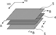
- FIG. 2 is a schematic perspective view showing an example of a laminated structure of a second porous layer / a first porous layer / a second porous layer.
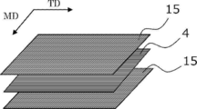
- FIG. 3 is a schematic perspective view showing a modified example of the laminated structure of FIG. Regarding the polyethylene microporous membrane of Example 1,
- FIG. 4 (a) is a scanning electron microscope (SEM) photograph when the surface layer is observed from the normal direction, and
- FIG. 4 (b) is polyethylene microporous along TD.
- SEM scanning electron microscope
- FIG. 4 (c) is a SEM photograph of the cut surface which cut
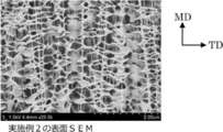
- FIG. 5 is an SEM photograph when the surface layer of the polyethylene microporous membrane of Example 2 was observed from the normal direction.
- FIG. 6A is a SEM photograph of the surface layer in the TD cross section
- FIG. 6B is a SEM photograph of the central layer in the TD cross section
- FIG. 6C is MD.
- the SEM photograph of the surface layer in a cross section is shown
- FIG.6 (d) is a SEM photograph of the center layer in MD cross section.
- FIG. 7 (a) is an SEM photograph when the surface layer is observed from the normal direction
- FIGS. 7 (b) and 7 (c) show each layer of the polyethylene microporous membrane. It is a SEM photograph.
- the numerical range indicated by using “to” indicates the range including the numerical values before and after “to” as the minimum value and the maximum value, respectively.
- the upper limit value or the lower limit value described in a certain numerical range may be replaced with the upper limit value or the lower limit value of another stepwise described numerical range.
- the upper limit value or the lower limit value described in a certain numerical range may be replaced with the values shown in the examples.
- machine direction means the lengthwise direction (that is, the conveying direction) of the polyolefin microporous membrane produced in a long shape
- width direction means the polyolefin microporous membrane. Means the direction orthogonal to the machine direction of the membrane.
- TD the "width direction”
- MD the "machine direction”
- the upper limit or the lower limit described in one numerical range may be replaced with the upper limit or the lower limit of the numerical range described in other stages. Good. Further, in the numerical range described in the present specification, the upper limit value or the lower limit value of the numerical range may be replaced with the value shown in the examples. Moreover, in this indication, “mass%” and “weight%” are synonymous, and “mass part” and “weight part” are synonymous. Furthermore, in the present disclosure, a combination of two or more preferable aspects is a more preferable aspect. In the present disclosure, the amount of each component in the composition or layer refers to the total amount of the plurality of substances present in the composition, unless a plurality of substances corresponding to each component are present in the composition, unless otherwise specified. Means
- process is included in this term as long as the intended purpose of the process is achieved, not only when it is an independent process but also when it cannot be clearly distinguished from other processes.
- the molecular weight when there is a molecular weight distribution represents the weight average molecular weight (Mw), unless otherwise specified.
- the polyolefin microporous membrane of the present disclosure has a structure that includes a polyolefin, a first rod-shaped crystal that extends in one direction, and a plurality of first plate-shaped crystals that are arranged in a separated state and that intersect with the first rod-shaped crystal.
- a first porous layer having, a second rod-shaped crystal containing a polyolefin and extending in the other direction intersecting with the one direction, and a plurality of second plate-like crystals arranged in a separated state and intersecting with the second rod-shaped crystal.
- the polyolefin microporous membrane of the present disclosure may have a plurality of first porous layers and a plurality of second porous layers, respectively. In addition to the first porous layer and the second porous layer, other You may have a layer of.
- the microporous membrane, the fibrillar polyolefin is connected to each other to form a three-dimensional network structure, has a plurality of micropores inside, a structure in which a plurality of micropores are connected to each other.
- it means a film in which gas or liquid can pass from one surface to the other surface.
- a biaxially stretched polyolefin microporous film is known as a film used for applications such as a liquid filter, but generally, when applied to remove gel-like foreign matter, the filter causes clogging.
- the filter causes clogging.
- a plurality of porous layers having a specific structure including a rod-shaped crystal and a plurality of plate-shaped crystals spaced apart by connecting with the rod-shaped crystal are stacked, and a plurality of porous layers are formed in each layer.
- the rod-like crystals are arranged so that their axial directions intersect with each other. As a result, it becomes possible to provide a polyolefin microporous membrane that has excellent gel-like foreign matter removal performance and is less likely to be clogged with foreign matter.
- the polyolefin microporous membrane of the present disclosure includes at least a first porous layer and a second porous layer, and has a laminated structure of two or more layers.
- the porous layer is a layer that has a plurality of pores inside and has a structure in which adjacent pores are connected to each other, and allows gas or liquid to pass from one surface to the other surface.
- the polyolefin microporous membrane of the present disclosure may have a laminated structure having two or more layers of at least one of the first porous layer and the second porous layer, and each has two or more layers of the first porous layer and the second porous layer. It may have a laminated structure, or may have a laminated structure in which one of the first porous layer and the second porous layer has an odd number layer and the other has an even number layer, for example, the following laminated structure.
- Second porous layer / first porous layer / second porous layer a) First porous layer / second porous layer b) Second porous layer / first porous layer / second porous layer c) Second porous layer / first porous layer / second porous layer Layer / first porous layer / second porous layer Among them, as shown in b) above, at least the second porous layer disposed on both surfaces of the first porous layer and the first porous layer, respectively.
- An embodiment having a laminated structure including layers is preferable.
- the porous layer in the present disclosure will be described by taking as an example the case of having the laminated structure of the above aspect a).
- the first porous layer is a layer having a structure including a first rod-shaped crystal extending in one direction and a plurality of first plate-shaped crystals arranged in a separated state and intersecting with the first rod-shaped crystal.
- the second porous layer is a second rod-shaped crystal that extends in the other direction that intersects with one direction in the first porous layer, and a plurality of second rod-shaped crystals that are arranged in a separated state and that intersect with the second rod-shaped crystal. It is a layer having a structure including plate crystals.
- the first porous layer and the second porous layer each include a rod-shaped crystal and a plurality of plate-shaped crystals, and the axial direction of the rod-shaped crystal in the first porous layer and the rod-shaped crystal in the second porous layer
- the axial direction and the axial direction intersect with each other. That is, the first porous layer and the second porous layer may be the same layer or different layers in terms of composition and structure, but at least a combination of a plurality of porous layers in which rod-shaped crystals are not in parallel relationship with each other is used.
- a structure that includes a first rod-shaped crystal that extends in one direction and a plurality of first plate-shaped crystals that are arranged in a separated state and intersect with the first rod-shaped crystal (hereinafter, may be referred to as a specific structure. ) Will be described with reference to FIG. 1
- the structure 1 shown in FIG. 1 has a first rod-shaped crystal 2 that is a rod-shaped crystal in which polyolefin molecules are arranged in one direction, that is, a uniaxial direction, and intersects with the first rod-shaped crystal 2, that is, skewered by the first rod-shaped crystal 2.
- the structure has the first plate-like crystal 3 which is a plurality of plate-like crystals connected to the first rod-like crystal.
- a plurality of plate-like crystals are juxtaposed in a state of being separated from each other along the axial direction of the rod-like crystals (first rod-like crystals) (intermittent arrangement state). ..
- a shish-kebab structure may be used.
- the shish kebab structure 1 is a structure that includes extended chain crystals that are rod-shaped crystals with one direction as an axis, and a plurality of folded chain crystals that are arranged side by side and intersect with the extended chain crystals in a separated state. Specifically, as shown in FIG.
- an extended-chain crystal extended-chain crystal; a so-called shish fibrous crystal
- a folded-chain crystal a so-called kebab crystal
- shishi a so-called kebab crystal
- the extended chain crystal in the shish kebab structure is one in which the molecular chain is stretched and oriented in the stretching direction by stretching, and the average distance between rod-shaped crystals represented by the extended chain crystal (interaxial distance of rod-shaped crystals) is Although not particularly limited, it is preferably, for example, 0.5 ⁇ m to 20 ⁇ m.
- extended chain crystals may be connected to each other via a folded chain crystal expanding in the axial direction, as shown in FIG.
- a plate crystal represented by a folded chain crystal in the shish kebab structure is a plate-like or block-like crystal part having two front and back surfaces in which lamella crystals are grown around an extended chain crystal that is stretched and oriented in the stretching direction.
- the shape may be flat, scale-like, or the like. However, the shape is not limited to these as long as it has two surfaces on the front and back sides.
- the average distance between plate-like crystals typified by folded chain crystals (distance between center thicknesses of plate-like crystals) arranged apart from each other along the axial direction of rod-like crystals is not particularly limited, but may be, for example, 0. It is preferably from 0.5 ⁇ m to 20 ⁇ m.
- the average value of the angles formed by the rod-shaped crystals represented by the extended chain crystals and the plate-shaped crystals represented by the folded chain crystals is preferably, for example, 30 ° to 150 °, more preferably 70 ° to 110. °.
- the angle formed by the rod-shaped crystal and the plate-shaped crystal refers to the angle formed by the axial direction of the rod-shaped crystal and the plane direction of the plane of the plate-shaped crystal.
- the “structure including a first rod-shaped crystal that extends in one direction and a plurality of first plate-shaped crystals that are arranged in a separated state and intersect with the first rod-shaped crystal” in the first porous layer has been described.
- the second porous layer “a structure including a second rod-shaped crystal extending in the other direction intersecting with one direction, and a plurality of second plate-shaped crystals arranged in a separated state and intersecting with the second rod-shaped crystal”
- the second rod-shaped crystal and the second plate-shaped crystal are the same as the first rod-shaped crystal and the first plate-shaped crystal, respectively, except that the arrangement angle of the rod-shaped crystal arranged in each porous layer is different.
- a porous structure of a polyolefin microporous membrane is formed by arranging a plurality of polyolefin units having a structure represented by a shish kebab structure.
- FIG. 2 is a schematic perspective view showing an example of a laminated structure of the second porous layer / the first porous layer / the second porous layer shown in the above aspect b), and FIG. 3 is the above aspect b). It is a schematic perspective view which shows the modification of.
- the polyolefin microporous membrane shown in FIG. 2 has a central layer (first porosity) having a shish kebab structure including extended chain crystals (first rod-shaped crystals) extending along the width direction (TD) orthogonal to the machine direction (MD).
- Layer) 4 and a surface layer (second porous layer) 5 which is provided on both surfaces of the central layer and has a shish-kebab structure including extended chain crystals (second rod-shaped crystals) extending along MD. It has a three-layer structure.
- the extended chain crystal that is the first rod-shaped crystal in the central layer 4 has a plurality of folded chain crystals (first plate-shaped crystals) grown in a form skewed by the extended chain crystal 2 as shown in FIG.
- the second rod-shaped crystal that is the extended chain crystal in the surface layer 5 also has a plurality of folded chain crystals (second plate-shaped crystal) grown in a form skewered by the extended chain crystal 2 as shown in FIG. ) 3 is connected (crossed).
- the polyolefin microporous membrane shown in FIG. 3 has a central layer (first porous layer) having a shish-kebab structure including extended chain crystals (first rod-shaped crystals) extending along the width direction (TD) orthogonal to the machine direction (MD). (Layer) 4 and the first shish-kebab structure including the first extended chain crystal (second rod-shaped crystal), which is provided on both surfaces of the central layer and (1) extends along MD, and (2) TD.
- a surface layer (second porous layer) 15 having a second shish-kebab structure including a second extended chain crystal (second rod-shaped crystal) extending along is formed into a three-layer structure.
- the extended chain crystal that is the first rod-shaped crystal in the central layer 4
- a plurality of folded chain crystals (grooved in a form skewered by the extended chain crystal 2 as in the polyolefin microporous film shown in FIG.
- the first plate crystals 3 are connected (crossed).
- the first extended chain crystals and the second extended chain crystals in the surface layer 15 intersect with each other and grow in a form skewed by the extended chain crystals 2 as shown in FIG.
- a plurality of folded chain crystals (second plate crystals) 3 are combined (crossed).
- a polyolefin microporous membrane having a structure such as the three-layer structure as described above, that is, a rod-shaped crystal and a structure including a plurality of plate-shaped crystals that are arranged in a separated state and intersect with the rod-shaped crystal is performed by, for example, stretching.
- the method for example, the stretching direction such as stretching in only one of MD and TD, the stretching ratio, etc.
- the type of solvent used when preparing the polyolefin solution, the heating temperature, and other conditions are selected according to the target layer structure. It can be done by For example, when stretching is performed, orientation can be achieved in the stretching direction.
- the extended chain crystal is “along the width direction” means that the axial direction of the extended chain crystal is ⁇ 30 ° to 30 ° with respect to the width direction (TD) of the polyolefin microporous film. Means within the range. Further, the fact that the extended chain crystal is “along the machine direction” means that the axial direction of the extended chain crystal is within the range of ⁇ 30 ° to 30 ° with respect to the machine direction (MD) of the polyolefin microporous film. Means that.
- the thickness of each layer can be in the following ranges:
- the thickness of the central layer is preferably 3 ⁇ m to 160 ⁇ m.
- the thickness of the surface layer per one surface is preferably 1 ⁇ m to 20 ⁇ m.
- the structure (for example, shish kebab structure) in the porous layer can be confirmed by a scanning electron microscope (SEM).
- SEM scanning electron microscope
- the layer structure of the porous layer in the polyolefin microporous membrane was obtained by cutting out a sample piece so that the machine direction (MD) and the width direction (TD) can be seen from the polyolefin microporous membrane produced in a long shape, and the SEM of the sample piece. The crystal structure can be confirmed by observing the photograph.
- Each of the first porous layer and the second porous layer contains at least one kind of polyolefin.
- the polyolefin include homopolymers of monomers such as ethylene, propylene, butylene, and methylpentene (polyethylene, polypropylene, polybutylene, polymethylpentene, etc.), or two or more monomers selected from the above monomers and the like. Or a mixture of one or more selected from the above homopolymers and copolymers. Of these, polyethylene is preferable.
- polyethylene high density polyethylene, a mixture of high density polyethylene and ultra high molecular weight polyethylene, etc. are suitable.
- polyethylene and a component other than polyethylene may be used in combination.
- components other than polyethylene include polypropylene, polybutylene, polymethylpentene, and copolymers of polypropylene and polyethylene.
- a plurality of polyolefins having different properties as polyolefins may be used. That is, a plurality of polyolefins having a poor degree of mutual compatibility and a combination of polymerization degrees or branching properties, in other words, a plurality of polyolefins having different crystallinity, stretchability and molecular orientation may be combined.
- the polyolefin composition contains 1% by mass or more of high molecular weight polyethylene having a weight average molecular weight of 1,000,000 to 6,000,000.
- high molecular weight polyethylene having a weight average molecular weight of 1,000,000 to 6,000,000
- low-molecular-weight polyethylene having a weight-average molecular weight of 200,000 or more and less than 1,000,000 are mixed in terms of easily forming a laminated structure having a shish-kebab structure.
- Compositions are preferred.
- the weight average molecular weight of the high molecular weight polyethylene As a lower limit of the weight average molecular weight of the high molecular weight polyethylene, 2,000,000 or more is more preferable, and 3,000,000 or more is further preferable. In this respect, by mixing an appropriate amount of two or more kinds of polyethylene, there is an effect of forming a network network structure associated with fibrillation at the time of stretching and increasing the void generation rate.
- the compounding ratio (hPE: lPE) of high molecular weight polyethylene (hPE) and low molecular weight polyethylene (lPE) is preferably 1:99 to 70:30 in terms of mass ratio.
- the low molecular weight polyethylene high density polyethylene having a density of 0.92 g / cm 3 to 0.96 g / cm 3 is preferable.
- the weight average molecular weight was determined by dissolving a sample of a polyolefin microporous membrane in o-dichlorobenzene with heating and using GPC (Alliance GPC 2000 type manufactured by Waters, column; GMH6-HT and GMH6-HTL) at a column temperature of 135 ° C. It can be obtained by measuring at a flow rate of 1.0 mL / min.
- GPC Alliance GPC 2000 type manufactured by Waters, column; GMH6-HT and GMH6-HTL
- the content of polyolefin in each porous layer of the microporous polyolefin membrane is preferably 90% by mass or more based on the total mass of each porous layer.
- each porous layer may contain an additive such as an organic or inorganic filler and a surfactant as a component other than the polyolefin as long as the effect of the present disclosure is not significantly impaired.
- the polyolefin microporous membrane of the present disclosure preferably has an average flow pore size of 20 nm to 300 nm.
- the polyolefin microporous membrane of the present disclosure has an average flow pore diameter in the above range in addition to the structure of the above-mentioned porous layer, is excellent in removing performance of gel-like foreign matter, and more effectively causes clogging by foreign matter. It can be suppressed.
- the average flow pore size is more preferably 30 nm or more, further preferably 40 nm or more, further preferably 50 nm or more, particularly preferably 60 nm or more.
- the average flow pore size is 300 nm or less, it is easy to maintain good performance of removing gel-like foreign matter.
- the average flow pore size is more preferably 290 nm or less, further preferably 280 nm or less, further preferably 270 nm or less, and particularly preferably 200 nm or less. The method of measuring the average flow pore size is as described in the section of Examples below.
- the method for adjusting the average flow pore diameter of the porous layer to the above range is not particularly limited, but, for example, the composition of the polyolefin, the concentration of the polyolefin in the raw material for forming the porous layer, the plurality of raw materials for forming the porous layer Mixing ratio when mixing solvents, heating temperature for squeezing out the solvent inside the sheet extruded into a sheet, extrusion pressure, heating time, stretching ratio, heat treatment (heat setting) temperature after stretching, extraction solvent
- a method of appropriately adjusting the immersion time, the annealing treatment temperature, the treatment time and the like can be mentioned.
- the ratio of the tensile strength in the machine direction (MD) to the tensile strength in the width direction (TD) is preferably 0.10 or more and 0.99 or less. ..
- the ratio (S MD / S TD ) of 0.99 or less is preferable in that the gel collection rate is further improved. The reason for this is not clear, but it is speculated that the ratio (S MD / S TD ) reflects the structure of the porous layer. That is, when the strength of TD is higher than that of MD, it is presumed that pores effective for gel collection are formed.
- the ratio (S MD / S TD ) is more preferably 0.94 or less.
- the ratio (S MD / S TD ) is 0.1 or more, the ratio between the MD tensile strength and the TD tensile strength is well balanced, and as a result, clogging is less likely to occur and the gel collection rate is good. It is estimated that From this point of view, the ratio (S MD / S TD ) is more preferably 0.2 or more, still more preferably 0.3 or more.
- the method for measuring the ratio (S MD / S TD ) is as described in the section of Examples below.
- the flow rate when ethanol is circulated in the thickness direction is 10 ml / min / cm 2 to 300 ml / min / cm 2 when converted under a pressure of 1 MPa. preferable.
- the flow rate of ethanol of the polyolefin microporous membrane is 10 ml / min / cm 2 or more, not only the water permeability of the liquid to be treated is easily obtained, but also stability during liquid passage (for example, to maintain a constant liquid passage amount) The stability of the power load and the stability of the liquid flow rate under a constant liquid pressure (constant power load) are easily obtained for a long period of time.
- the ethanol flow rate is more preferably 15 ml / min / cm 2 or more.
- the ethanol flow rate is 300 ml / min / cm 2 or less, it becomes easy to highly collect the gel-like foreign matter.
- the ethanol flow rate is more preferably 250 ml / min / cm 2 or less, further preferably 200 ml / min / cm 2 or less, and particularly preferably 100 ml / min / cm 2 or less.
- the liquid permeation performance can be evaluated using the liquid permeation amount (Vs) obtained from the following equation from the ethanol flow rate as an index, and the details of the calculation method are as described in the section of Examples described later.
- Permeation rate (Vs) V / (Tl ⁇ S) ...
- V Amount of ethanol [ml]
- Tl Permeation time of all ethanol [min]
- S Liquid permeation area of the liquid permeation cell [cm 2 ]
- the polyolefin microporous membrane of the present disclosure preferably has a thickness of 5 ⁇ m to 200 ⁇ m.
- the film thickness of the polyolefin microporous film is 5 ⁇ m or more, good mechanical strength can be easily obtained, and handling property when processing the polyolefin microporous film and durability in long-term use when processed into, for example, a filter cartridge. Is easy to obtain.
- a thicker layer is advantageous. From this viewpoint, the thickness of the microporous polyolefin membrane is more preferably 10 ⁇ m or more, further preferably 15 ⁇ m or more, and particularly preferably 20 ⁇ m or more.
- the thickness of the microporous polyolefin membrane is 200 ⁇ m or less, not only is it easy to obtain good liquid permeation performance with a single membrane, but also when it is processed into, for example, a filter cartridge of a predetermined size, a larger filtration area is obtained. Easy to obtain.
- the flow rate design and structure design of the filter when processing the microporous polyolefin membrane can be easily performed.
- the thickness of the polyolefin microporous film is more preferably 180 ⁇ m or less, further preferably 150 ⁇ m or less, further preferably 100 ⁇ m or less, and particularly preferably 80 ⁇ m or less. The method of measuring the thickness is as described in the section of Examples below.
- the polyolefin microporous membrane of the present disclosure preferably has a porosity of 55% to 85%.
- the porosity of the polyolefin microporous membrane is 55% or more, the liquid permeation performance becomes good and clogging hardly occurs. From this viewpoint, the porosity is more preferably 60% or more.
- the porosity is 85% or less, the mechanical strength of the polyolefin microporous film becomes good and the handling property also improves. In addition, the ability to collect gel-like foreign matter is also improved. From this viewpoint, the porosity is more preferably 80% or less, further preferably 75% or less.
- the polyolefin microporous membrane of the present disclosure preferably has a Gurley value of 0.1 sec / 100 ml to 200 sec / 100 ml.
- the Gurley value of the polyolefin microporous film is 0.1 sec / 100 ml or more, the ability to collect gel-like foreign matter becomes good.
- the Gurley value is more preferably 10 seconds / 100 ml or more.
- the Gurley value is 200 seconds / 100 ml or less, the liquid permeability of the liquid to be treated becomes good. It is also preferable from the viewpoint of preventing clogging. From this viewpoint, the Gurley value is more preferably 150 seconds / 100 ml or less, further preferably 100 seconds / 100 ml or less.
- the method for measuring the Gurley value is as described in the section of Examples described later.
- the polyolefin microporous membrane of the present disclosure can be used as a substrate for liquid filters.
- the polyolefin microporous membrane may be used as a liquid filter substrate that has been processed to impart an affinity with a chemical liquid. Further, the microporous polyolefin membrane may be processed into a cartridge shape and used as a substrate for a liquid filter.
- a porous base material such as polytetrafluoroethylene
- a porous base material such as polytetrafluoroethylene
- the polyolefin microporous membrane of the present disclosure when used as a substrate for a liquid filter, compared with a conventional porous substrate such as polytetrafluoroethylene, it has a good affinity with a chemical liquid, and therefore, for example, a filter and a chemical liquid There is an advantage that processing for giving affinity is facilitated.
- the filter cartridge is loaded into the filter housing and the filtration of the chemical liquid is started, when the chemical liquid is filled in the filter, air is less likely to build up in the filter cartridge, which improves the filtration yield of the chemical liquid.
- the content of halogen element in polyolefin such as polyethylene itself is low, it is easy to handle the used filter cartridge, and it is expected that the environmental load can be reduced.
- the polyolefin microporous membrane of the present disclosure can be used for applications other than liquid filter substrates, and can be expected to be applied to applications such as gas filters, gas-liquid separation membranes, and blood cell separation membranes. ..
- the polyolefin microporous membrane of the present disclosure can be suitably manufactured by the method shown below. That is, it is preferable to use a manufacturing method in which the following steps (I) to (IV) are sequentially performed.
- a solution containing the polyolefin composition and a solvent is prepared, but it is preferable to prepare a solution containing a nonvolatile solvent having a boiling point of 210 ° C. or higher at least at atmospheric pressure.
- the non-volatile solvent used for preparing the present solution include liquid paraffin, paraffin oil, mineral oil, castor oil and the like, and liquid paraffin is preferable.
- the volatile solvent is not particularly limited as long as it can swell or dissolve the polyolefin well, and liquid solvents such as tetralin, ethylene glycol, decalin, toluene, xylene, diethyltriamine, ethylenediamine, dimethylsulfoxide, and hexane. preferable.
- the volatile solvents may be used alone or in combination of two or more. Among them, the volatile solvent is preferably decalin or xylene.
- the concentration of the polyolefin composition is preferably 10% by mass to 40% by mass, more preferably 13% by mass to 25% by mass.
- the concentration of the polyolefin composition is 10% by mass or more, the mechanical strength can be further increased, so that the handling property becomes better, and further, the polyolefin microporous film becomes easier to form. Further, when the concentration of the polyolefin composition is 40% by mass or less, it tends to easily form pores.
- the solution prepared in the step (I) is melt-kneaded, and the obtained melt-kneaded product is extruded from a die and cooled and solidified to obtain a gel-like molded product.
- the extrudate is extruded from a die within a temperature range of the melting point to (melting point + 65 ° C.) of the polyolefin composition to obtain an extrudate, and the extrudate obtained is cooled to obtain a gel-like molded product.
- the molded product is preferably a molded product shaped into a sheet.
- the cooling may be quenching in an aqueous solution or an organic solvent, or may be casting on a cooled metal roll.
- the cooling temperature is preferably 5 ° C to 40 ° C. It is preferable to prepare a gel-like sheet while providing a water flow on the surface layer of the water bath so that the solvent released from the gelled sheet in the water bath and floating on the water surface does not adhere to the sheet again.
- the step (III) is a step of stretching the gel-like molded product in one of the machine direction and the width direction.
- the stretching in the step (III) is preferably uniaxial stretching in the machine direction (MD) or the width direction (TD) orthogonal to MD, and more preferably uniaxial stretching in TD without stretching in MD. ..
- the stretching ratio is preferably 3 to 50 times, more preferably 4 to 20 times. When the stretching ratio is 3 times or more, not only the polyolefin microporous film is more easily formed, but also the structure represented by the shish-kebab structure as described above is easily formed.
- Stretching is preferably performed with the solvent left in a suitable state.
- the stretching temperature is preferably 80 ° C to 140 ° C, more preferably 100 ° C to 130 ° C.
- the heat setting temperature is preferably 110 ° C. to 145 ° C., and 120 ° C. to 140 ° C., from the viewpoint of controlling the liquid permeation performance of the polyolefin microporous membrane and the removal performance of gelled foreign matter that is one of the filtration targets. C is more preferred. If the heat setting temperature is 145 ° C. or lower, the removal performance of the filtration object of the polyolefin microporous membrane will be better, and if the heat setting temperature is 110 ° C. or higher, it is suitable for maintaining better liquid permeation performance. ing.
- Step (IV) is a step of extracting and washing the solvent from the inside of the stretched intermediate molded product.
- step (IV) in order to extract the solvent from the inside of the stretched intermediate molded product (stretched film), it is preferable to wash with a solvent of a halogenated hydrocarbon such as methylene chloride or a hydrocarbon such as hexane.
- a solvent of a halogenated hydrocarbon such as methylene chloride or a hydrocarbon such as hexane.
- the tank is divided into several stages, the cleaning solvent is poured from the downstream side of the polyolefin microporous membrane transportation step, and the cleaning solvent is flowed toward the upstream side of the step transportation,
- the purity of the washing solvent in the downstream tank is preferably higher than that in the upstream layer.
- heat setting may be performed by annealing depending on the performance required for the microporous polyolefin membrane.
- the annealing treatment is preferably performed at 50 ° C. to 150 ° C., more preferably 50 ° C. to 140 ° C., from the viewpoint of transportability in the process.
- microporous polyolefin membrane having both excellent liquid permeation performance under high pressure and excellent performance of removing an object to be filtered even though it is a thin film.
- the liquid filter according to the present disclosure includes the polyolefin microporous membrane according to the present disclosure described above, and can be used after being processed into a shape such as a cartridge as necessary. Further, the liquid filter may be subjected to a processing that imparts an affinity with the chemical liquid, if necessary.
- the liquid filter allows a liquid to be treated containing or possibly containing organic particles, inorganic particles, gel-like substances, etc. to pass through and remove the particles and gel-like substances from the liquid to be treated. Further, the liquid filter can be used, for example, in a semiconductor manufacturing process, a display manufacturing process, a polishing process, and the like.
- the polyolefin microporous membrane of the present disclosure has a purpose other than the above-described liquid filter, for example, for the purpose of separation, purification, concentration, fractionation, detection, etc. of a substance dispersed or dissolved in a fluid (that is, gas or liquid). May be used. Specific examples include various filters used for water purification, sterilization, desalination, seawater desalination, artificial dialysis, pharmaceutical manufacturing, food manufacturing, in-vitro diagnostic equipment, gas-liquid separation, etc .; chromatography carriers; and the like.
- Test strength Using a tensile tester (RTE-1210 manufactured by Orientec Co., Ltd.), a test piece (width 15 mm, length 50 mm) obtained by cutting a polyethylene microporous film into a strip shape was subjected to MD and TD at a speed of 200 mm / min. Each was pulled and the tensile strength was measured. Based on the measured values, the ratio of the tensile strength in the machine direction to the tensile strength in the width direction was obtained.
- RTE-1210 manufactured by Orientec Co., Ltd.
- Gurley value The Gurley value (second / 100 ml) of the polyethylene microporous membrane having an area of 642 mm 2 was measured by a method based on Japanese Industrial Standard (JIS) P8117.
- a palm porometer porous material automatic pore size distribution measurement system [Capillary Flow Porometer] manufactured by PMI Co., Ltd. is used to apply a pore size distribution measurement test method [half-dry method (ASTM E1294-89)] to determine the average flow pore size. It was measured.
- the test solution used was perfluoropolyester (trade name: Galwick) (interfacial tension value: 15.9 dyne / cm), the measurement temperature was 25 ° C., and the measurement pressure was changed in the range of 0 kPa to 1500 kPa. ..
- the thickness of the polyethylene microporous film was measured at 20 points, and the measured values were averaged.
- the contact terminal was a cylindrical one having a bottom surface of 0.5 cm in diameter, and the measurement pressure was 0.1 N.
- the polyethylene microporous membrane was cut into 10 cm ⁇ 10 cm to prepare a sample piece, the mass of the sample piece was measured, and the measured mass was divided by the area to determine the basis weight.
- ⁇ (%) ⁇ 1-Ws / (ds ⁇ t) ⁇ ⁇ 100 Ws: basis weight of microporous polyolefin membrane (g / m 2 ) ds: true density of polyolefin (g / cm 3 ). t: thickness of the microporous polyolefin membrane ( ⁇ m)
- the polyethylene microporous membrane was previously immersed in ethanol and dried at room temperature. This polyethylene microporous membrane was set in a stainless liquid permeation cell (liquid permeation area Scm 2 ) having a diameter of 47 mm. After wetting the polyethylene microporous membrane on the liquid permeable cell with a small amount (0.5 ml) of ethanol, the amount V of ethanol (100 ml) previously measured at a differential pressure of 90 kPa was passed through, and the total amount of ethanol was passed through. The time Tl (min) required for was measured.
- a soybean milk (brand: Kikkoman tasty unadjusted soybean milk) was diluted with water 400000 times to prepare a gel-like liquid.
- the polyethylene microporous membrane was set in a stainless liquid-permeable cell having a diameter of 47 mm.
- the polyethylene microporous membrane on the liquid-permeable cell was wetted with a small amount (0.5 ml) of ethanol, and then water (20 ml) preliminarily measured at a differential pressure of 90 kPa was permeated.
- the gel-like liquid (20 ml) was repeatedly permeated, and the time T1 (sec) required for permeation of the total amount of gel-like liquid for the first time and the permeation of the total amount of gel-like liquid for the fifth time
- the required time T2 (sec) was measured. From the time required for the first permeation and the time required for the fifth permeation, the increase rate ⁇ T% of the permeation time due to gel collection was calculated from the following formula, and the gel foreign matter collection performance and clogging It was used as a standard.
- Example 1 A polyethylene composition was used in which 10 parts by mass of high molecular weight polyethylene (PE1) having a weight average molecular weight of 4.6 million and 7 parts by mass of low molecular weight polyethylene (PE2) having a weight average molecular weight of 560,000 were mixed.
- the polyethylene composition was mixed with 83 parts by mass of liquid paraffin prepared in advance so that the total concentration of the polyethylene resin was 17% by mass to prepare a polyethylene solution.
- This polyethylene solution is extruded into a sheet form from a die at a temperature of 150 ° C, the extruded sheet is cooled in a water bath of 19 ° C, and the mixed solvent is released from the gelled sheet in the water bath and floats on the water surface.
- a gel-like sheet (base tape) was prepared while preventing the particles from reattaching to the sheet.
- the produced base tape was conveyed while applying a pressure of 0.06 MPa on a roller heated to 90 ° C., and a part of liquid paraffin was removed from the inside of the base tape. At this time, the base tape was not stretched in the transport direction (MD). Then, the base tape was stretched at a temperature of 105 ° C. in the width direction (TD) at a draw ratio of 9 times (transverse stretching), and immediately after transverse stretching, heat treatment (heat setting) was performed at 136 ° C.
- the heat-fixed base tape was continuously immersed in a methylene chloride bath divided into two tanks for 200 seconds each to extract liquid paraffin.
- the purity of the cleaning solvent in each tank is (low) first layer ⁇ second tank (high). is there.
- methylene chloride was dried and removed at 40 ° C., and annealed while being conveyed on a roller heated to 120 ° C.
- a filter substrate made of a polyethylene microporous membrane polyolefin microporous membrane
- the structure of the polyethylene microporous membrane obtained as described above was confirmed by the following method. Specifically, the obtained polyethylene microporous membrane was observed by SEM as described above, and the crystal structure of the polymer in the membrane and the directions of MD and TD were analyzed from the observation photograph. As a result, the layer structure of the polyethylene microporous membrane was a laminated structure composed of three layers, and as shown in FIG. 3, on both surfaces of the central layer (first porous layer), along (1) MD, respectively. A surface layer (second porous layer) having a first shish-kebab structure containing a first extended chain crystal and a second shish-kebab structure containing a second extended chain crystal (2) extending along TD. I confirmed that I had it.
- FIG. 4A is a SEM photograph when the surface layer is observed from the normal direction.
- the surface layer has extended chain crystals that are rod-shaped crystals extending in both MD and TD and oriented so as to intersect each other. This point was similarly observed on both one side and the other side of the polyethylene microporous membrane.
- the extended chain crystal has a plurality of folded chain crystals that are plate-like crystals that intersect the extended chain crystal so as to be skewered, are separated from each other, and are bonded to the extended chain crystal.
- FIG. 4B is a SEM photograph of a cut surface obtained by cutting the polyethylene microporous film along the TD. Extended chain crystals extending along TD were observed in the surface layer, and extended chain crystals were also observed in the center layer.
- FIG. 4C is a SEM photograph of a cut surface obtained by cutting the polyethylene microporous film along the MD. No extended chain crystals were found in the central layer, and only plate-like crystals (folded chain crystals) intersecting with extended chain crystals were seen, but extended chain crystals extending along MD were observed in the surface layer. Admitted.
- Example 2 For a liquid filter comprising a polyethylene microporous membrane (polyolefin microporous membrane) in the same manner as in Example 1 except that the composition of the solution and the extrusion conditions were changed as shown in Table 1 below. A base material was obtained.
- the layer structure of the polyethylene microporous membrane obtained in Example 2 is a laminated structure composed of three layers, and as shown in FIG. 2, a central layer having a shish kebab structure including extended chain crystals extending along TD ( It was confirmed to have a first porous layer) and a surface layer (second porous layer) having a shish kebab structure provided on both surfaces of the central layer and having extended chain crystals extending along MD.
- Example 1 the film had a denser structure on the surface layer side in the film thickness direction, whereas the structure in the central portion was rougher than the surface layer.
- An SEM photograph of the surface layer of the polyethylene microporous membrane is shown in FIG. FIG. 5 is an SEM photograph when the surface layer is observed from the normal direction.
- the SEM photograph of each layer of the polyethylene microporous membrane is shown in FIG. 6A shows a SEM photograph of the surface layer and FIG. 6B shows a SEM photograph of the center layer of the cross section (cross section taken along the line AA of FIG. 2) obtained by cutting the polyethylene microporous membrane along the TD. Indicates. In the structure along the TD, as shown in FIG.
- FIG. 6A folded chain crystals that are plate-like crystals are mainly observed in the surface layer, and extended chain crystals that are rod-shaped crystals are mainly observed in the center layer. It was seen.
- FIG. 6C shows a SEM photograph of the surface layer
- FIG. 6D shows a SEM photograph of the central layer. Indicates.
- FIG. 6C elongated chain crystals that are rod-like crystals are mainly observed in the surface layer, and folded chain crystals that are plate-like crystals are mainly observed in the central layer. It was seen.
- a polyethylene composition was used in which 14 parts by mass of high molecular weight polyethylene (PE1) having a weight average molecular weight of 4.6 million and 11 parts by mass of low molecular weight polyethylene (PE2) having a weight average molecular weight of 560,000 were mixed.
- a polyethylene solution was prepared by mixing a polyethylene composition with 75 parts by mass of decalin (decahydronaphthalene) prepared in advance so that the total concentration of the polyethylene resin would be 25% by mass.
- This polyethylene solution was extruded into a sheet form from a die at a temperature of 154 ° C., and the extruded sheet was cooled in a water bath of 20 ° C. to prepare a gel-like sheet (base tape).
- the prepared base tape is pre-dried in a temperature atmosphere of 60 ° C. for 5 minutes and in a temperature atmosphere of 70 ° C. for 5 minutes, and then a magnification of 1.5 times in the transport direction (MD) of the base tape.
- MD transport direction
- the primary drawing was performed.
- main drying was performed for 5 minutes in a temperature atmosphere of 57 ° C. (the residual amount of the solvent in the base tape at this time was less than 1% by mass).
- the base tape is further stretched in MD at a temperature of 95 ° C. at a magnification of 6.0 times (longitudinal stretching) as a secondary stretching, and subsequently in the width direction (TD) at a temperature of 130 ° C. It was stretched at 9.0 times (horizontally stretched).
- heat treatment heat setting
- the heat-fixed base tape was continuously dipped in a methylene chloride bath divided into two tanks for 30 seconds each. Then, methylene chloride was removed by drying at 40 ° C.
- a liquid filter substrate made of a polyethylene microporous membrane for comparison was obtained.
- a polyethylene composition was used in which 3 parts by mass of high-molecular-weight polyethylene (PE1) having a weight-average molecular weight of 4.6 million and 14 parts by mass of low-molecular-weight polyethylene (PE2) having a weight-average molecular weight of 560,000 were mixed.
- PE1 high-molecular-weight polyethylene
- PE2 low-molecular-weight polyethylene
- a polyethylene composition and a mixed solvent of 51 parts by mass of liquid paraffin and 32 parts by mass of decalin (decahydronaphthalene) prepared in advance are mixed so that the total concentration of the polyethylene resin is 17% by mass, and a polyethylene solution is prepared.
- decalin decahydronaphthalene
- This polyethylene solution was extruded into a sheet form from a die at a temperature of 162 ° C., the extruded sheet was cooled in a water bath of 22 ° C., and the mixed solvent released from the gelled sheet in the water bath and floating on the water surface was removed.
- a gel-like sheet (base tape) was prepared while avoiding reattachment to the sheet.
- the produced base tape was dried under a temperature atmosphere of 60 ° C. for 5 minutes and under a temperature atmosphere of 95 ° C. for 5 minutes to remove decalin from the base tape. Subsequently, the base tape was conveyed on a roller heated to 90 ° C.
- the base tape was stretched (longitudinal) at a temperature of 90 ° C. at a magnification of 5.5 times in the transport direction (MD) of the base tape, and subsequently at a temperature of 106 ° C. in the width direction (TD). It was stretched 10 times (transverse stretching). Immediately after transverse stretching, heat treatment (heat setting) was performed at 140 ° C. Next, the heat-fixed base tape was continuously immersed in a methylene chloride bath divided into two tanks for 60 seconds each to extract liquid paraffin.
- the purity of the cleaning solvent is (low) first layer ⁇ second tank (high). Then, methylene chloride was dried and removed at 40 ° C., and annealed while being conveyed on a roller heated to 120 ° C. As described above, a liquid filter substrate made of a polyethylene microporous membrane for comparison was obtained.
- a polyethylene composition was used in which 10 parts by mass of a high-molecular-weight polyethylene (PE1) having a weight-average molecular weight of 4.6 million and 7 parts by mass of a low-molecular-weight polyethylene (PE2) having a weight-average molecular weight of 560,000 were mixed.
- the polyethylene composition was mixed with 83 parts by mass of liquid paraffin prepared in advance so that the total concentration of the polyethylene resin was 17% by mass to prepare a polyethylene solution.
- This polyethylene solution was extruded into a sheet form from a die at a temperature of 150 ° C., the extruded sheet was cooled in a water bath at 19 ° C., and the mixed solvent released from the gelled sheet in the water bath and floating on the water surface
- a gel-like sheet (base tape) was prepared while avoiding reattachment to the sheet.
- the prepared base tape is continuously immersed in a methylene chloride bath divided into two tanks for 200 seconds each without removing part of the liquid paraffin, transverse stretching and heat setting. And liquid paraffin was extracted.
- the purity of the cleaning solvent is (low) first layer ⁇ second tank (high).
- methylene chloride was dried and removed at 40 ° C., and annealed while being conveyed on a roller heated to 120 ° C. After that, the base tape was stretched in the width direction (TD) at a temperature of 105 ° C. at a draw ratio of 9 times (transverse stretching), and immediately thereafter, heat treatment (heat setting) was performed at 136 ° C.
- FIG. 7A is an SEM photograph when the surface layer is observed from the normal direction. SEM photographs of each layer of this polyethylene microporous membrane are shown in FIGS. 7 (b) and 7 (c).
- the polyethylene microporous membrane obtained in Comparative Example 5 had rod-like crystals extending branchwise in any direction, but did not have a structure in which the rod-like crystals were oriented in one direction. Further, as shown in FIGS.
- a plate in which rod-like crystals extending in an arbitrary direction in a branch shape are combined with the rod-like crystals so as to be skewered in both the surface layer and the central layer No state crystals, that is, crystals having two surfaces on the front and back were observed, and no shish kebab structure could be recognized.
- a plurality of porous layers having a specific structure including a rod-shaped crystal and a plurality of plate-shaped crystals that are spaced apart by connecting with the rod-shaped crystal are stacked, and the plurality of porous layers are formed into the rod-shaped crystal of each layer.
- the polyolefin microporous membrane of the example having a structure in which the axial directions intersect each other was excellent in the ability to remove gel-like foreign matter, and the occurrence of clogging due to foreign matter was suppressed to a small extent.
- the polyolefin microporous film of Comparative Example not only was the gel-like foreign matter removability low, but the foreign matter frequently clogged.
Abstract
Provided in an embodiment of the present invention is a polyolefin microporous membrane comprising: a first porous layer containing a polyolefin and having a structure including a first rod-shaped crystal extending in one direction and a plurality of first plate-shaped crystals disposed at intervals from one another and intersecting the first rod-shaped crystal; and a second porous layer containing a polyolefin and having a structure including a second rod-shaped crystal extending in another direction intersecting the one direction and a plurality of second plate-shaped crystals disposed at intervals from one another and intersecting the second rod-shaped crystal.
Description
本開示は、ポリオレフィン微多孔膜及び液体フィルターに関する。
The present disclosure relates to a polyolefin microporous membrane and a liquid filter.
従来、液体フィルター、透湿防水膜、及びエアフィルタ等の各種用途において、ポリオレフィン微多孔膜が用いられている。
Conventionally, polyolefin microporous membranes have been used in various applications such as liquid filters, moisture-permeable waterproof membranes, and air filters.
ポリオレフィン微多孔膜は、相分離法又は延伸法を利用して作製することが代表的な方法として知られている。
相分離法は、高分子溶液の相分離現象により細孔を形成する技術であり、例えば熱により相分離が誘起される熱誘起相分離法、高分子の溶媒に対する溶解度特性を利用した非溶媒誘起相分離法などがある。また、熱誘起相分離と非溶媒誘起相分離の両方の技術を組み合わせたり、更には延伸により孔構造の形及び大きさを調整し、バリエーションを増大させることも可能である。 It is known that a polyolefin microporous membrane is typically produced by using a phase separation method or a stretching method.
The phase separation method is a technique for forming pores by a phase separation phenomenon of a polymer solution, for example, a thermally induced phase separation method in which phase separation is induced by heat, a non-solvent induced method utilizing the solubility characteristic of a polymer in a solvent. There is a phase separation method. Further, it is also possible to increase the variation by combining both the techniques of thermally-induced phase separation and non-solvent-induced phase separation, or by adjusting the shape and size of the pore structure by stretching.
延伸法は、例えば特開2010-053245号公報、特開2010-202828号公報、特開平7-246322号公報及び国際公開第2014/181760号に記載されるように、シート状に成形されたポリエチレン原反シートを延伸し、速度、倍率、温度等の延伸条件を調整して、結晶構造中の非晶質部分を引き伸ばし、ミクロフィブリルを形成しながらラメラ層の間に微細孔を形成する方法である。これらの中でも、生産性、等方性、均一性等の観点から、液体フィルター等の用途においては、二軸延伸ポリオレフィン微多孔膜が多く用いられている。
The stretching method is, for example, as described in JP 2010-053245 A, JP 2010-202828 A, JP 7-246322 A and WO 2014/181760, a polyethylene molded into a sheet shape. By stretching the raw sheet, adjusting the stretching conditions such as speed, magnification, temperature, etc. to stretch the amorphous part in the crystal structure and forming micropores between the lamella layers while forming microfibrils. is there. Among these, biaxially stretched polyolefin microporous membranes are often used in applications such as liquid filters from the viewpoints of productivity, isotropy, uniformity, and the like.
ところで、液体フィルター等の用途では、高分子等からなるゲル状の異物を捕集対象として除去する場合がある。
By the way, in applications such as liquid filters, gel-like foreign substances made of polymers may be removed as collection targets.
しかしながら、ゲル状の異物は、容易に変形しやすく、特開2010-053245号公報、特開2010-202828号公報、特開平7-246322号公報及び国際公開第2014/181760号に記載されるような従来の二軸延伸膜では、目詰まりが発生しやすいばかりか、異物の捕捉不良、膜表面の孔の閉塞といった問題が生じる場合がある。そのため、ゲル状の異物を長期に亘って継続的に良好に除去することが可能なポリオレフィン微多孔膜は提案されるに至っていなかったのが実状である。
However, the gel-like foreign matter is easily deformed and is described in JP 2010-053245 A, JP 2010-202828 A, JP 7-246322 A and WO 2014/181760. Such conventional biaxially stretched membranes not only tend to be clogged, but may also have problems such as improper capture of foreign matter and clogging of pores on the membrane surface. Therefore, the reality is that a polyolefin microporous film capable of continuously and satisfactorily removing gel foreign matter for a long time has not been proposed.
そこで、本開示は、ゲル状の異物の除去性能に優れ、異物による目詰まりの少ないポリオレフィン微多孔膜及び液体フィルターを提供することを目的とする。
Therefore, an object of the present disclosure is to provide a polyolefin microporous membrane and a liquid filter that are excellent in the ability to remove gel-like foreign matter and have less clogging by foreign matter.
課題を解決するための具体的手段には、以下の態様が含まれる。
<1> ポリオレフィンを含み、一方向に伸びる第1棒状結晶、及び離間状態で配置され、かつ、前記第1棒状結晶と交差する複数の第1板状結晶を含む構造を有する第1の多孔層と、ポリオレフィンを含み、前記一方向と交差する他方向に伸びる第2棒状結晶、及び離間状態で配置され、かつ、前記第2棒状結晶と交差する複数の第2板状結晶を含む構造を有する第2の多孔層と、を備えたポリオレフィン微多孔膜である。
<2> 平均流量孔径が、20nm~300nmである<1>に記載のポリオレフィン微多孔膜である。
<3> 少なくとも、前記第1の多孔層と、前記第1の多孔層の両方の面にそれぞれ配置された前記第2の多孔層と、を含む積層構造を有する<1>又は<2>に記載のポリオレフィン微多孔膜である。
<4> 前記第1の多孔層及び前記第2の多孔層における前記構造は、軸方向に伸びる棒状晶である伸びきり鎖結晶、及び伸びきり鎖結晶と交差して離間状態で並置された複数の折りたたみ鎖結晶を含むシシカバブ構造である<1>~<3>のいずれか1つに記載のポリオレフィン微多孔膜である。
<5> 前記一方向が機械方向に直交する幅方向であり、前記他方向が機械方向であり、前記幅方向の引張強度に対する前記機械方向の引張強度の比が、0.10以上0.99以下である、<1>~<4>のいずれか1つに記載のポリオレフィン微多孔膜である。 Specific means for solving the problems include the following aspects.
<1> A first porous layer having a structure containing a polyolefin, a first rod-shaped crystal that extends in one direction, and a plurality of first plate-shaped crystals that are arranged in a separated state and that intersect with the first rod-shaped crystal. And a second rod-shaped crystal that contains polyolefin and extends in the other direction that intersects the one direction, and a plurality of second plate-shaped crystals that are arranged in a separated state and that intersect with the second rod-shaped crystal. And a second porous layer, which is a microporous polyolefin membrane.
<2> The polyolefin microporous membrane according to <1>, which has an average flow pore diameter of 20 nm to 300 nm.
<3> In <1> or <2> having a laminated structure including at least the first porous layer and the second porous layers respectively arranged on both surfaces of the first porous layer. It is the described polyolefin microporous membrane.
<4> The structures in the first porous layer and the second porous layer are extended chain crystals, which are rod-shaped crystals extending in the axial direction, and a plurality of extended chain crystals that are juxtaposed in a spaced state intersecting with the extended chain crystals. The microporous polyolefin film according to any one of <1> to <3>, which has a shish-kebab structure including a folded chain crystal.
<5> The one direction is the width direction orthogonal to the machine direction, the other direction is the machine direction, and the ratio of the tensile strength in the machine direction to the tensile strength in the width direction is 0.10 or more and 0.99. The polyolefin microporous membrane according to any one of <1> to <4> below.
<6> エタノールを厚み方向に流通させた際の流量が、1MPaの圧力下で換算して10ml/min/cm2~300ml/min/cm2である、<1>~<5>のいずれか1つに記載のポリオレフィン微多孔膜である。
<7> 厚みが、5μm~200μmである、<1>~<6>のいずれか1つに記載のポリオレフィン微多孔膜である。
<8> ガーレ値が、0.1秒/100ml~200秒/100mlである、<1>~<7>のいずれか1つに記載のポリオレフィン微多孔膜である。
<9> 空孔率が、55%~85%である、<1>~<8>のいずれか1つに記載のポリオレフィン微多孔膜である。
<10> 液体フィルター用基材である、<1>~<9>のいずれか1つに記載のポリオレフィン微多孔膜である。
<11> <1>~<10>のいずれか1つに記載のポリオレフィン微多孔膜を含む液体フィルターである。 <6> Any one of <1> to <5>, in which the flow rate of ethanol in the thickness direction is 10 ml / min / cm 2 to 300 ml / min / cm 2 at a pressure of 1 MPa. It is the polyolefin microporous membrane described in 1.
<7> The polyolefin microporous membrane according to any one of <1> to <6>, having a thickness of 5 μm to 200 μm.
<8> The polyolefin microporous membrane according to any one of <1> to <7>, which has a Gurley value of 0.1 seconds / 100 ml to 200 seconds / 100 ml.
<9> The polyolefin microporous membrane according to any one of <1> to <8>, which has a porosity of 55% to 85%.
<10> The polyolefin microporous membrane according to any one of <1> to <9>, which is a substrate for liquid filters.
<11> A liquid filter including the polyolefin microporous membrane according to any one of <1> to <10>.
本開示によれば、ゲル状の異物の除去性能に優れ、異物による目詰まりの少ないポリオレフィン微多孔膜及び液体フィルターを提供することができる。
According to the present disclosure, it is possible to provide a polyolefin microporous membrane and a liquid filter that have excellent gel foreign matter removal performance and are less likely to be clogged with foreign matter.
以下、本開示のポリオレフィン微多孔膜及び液体フィルターについて詳細に説明する。
なお、以下で説明する本開示の実施形態、実施形態に関する説明、及び実施例等は、本開示のポリオレフィン微多孔膜及び液体フィルターを例示するものであり、本開示の範囲を制限するものではない。 Hereinafter, the polyolefin microporous membrane and the liquid filter of the present disclosure will be described in detail.
The embodiments of the present disclosure, the description of the embodiments, the examples, and the like described below are examples of the polyolefin microporous membrane and the liquid filter of the present disclosure, and do not limit the scope of the present disclosure. ..
本明細書において、「~」を用いて示された数値範囲は、「~」の前後に記載される数値をそれぞれ最小値及び最大値として含む範囲を示す。本開示に段階的に記載されている数値範囲において、ある数値範囲で記載された上限値又は下限値は、他の段階的な記載の数値範囲の上限値又は下限値に置き換えてもよい。また、本開示に記載されている数値範囲において、ある数値範囲で記載された上限値又は下限値は、実施例に示されている値に置き換えてもよい。
In the present specification, the numerical range indicated by using "to" indicates the range including the numerical values before and after "to" as the minimum value and the maximum value, respectively. In the numerical ranges described stepwise in the present disclosure, the upper limit value or the lower limit value described in a certain numerical range may be replaced with the upper limit value or the lower limit value of another stepwise described numerical range. Further, in the numerical range described in the present disclosure, the upper limit value or the lower limit value described in a certain numerical range may be replaced with the values shown in the examples.
また、ポリオレフィン微多孔膜に関し、「機械方向」とは、長尺状に製造されるポリオレフィン微多孔膜の長尺方向(即ち、搬送方向)を意味し、「幅方向」とは、ポリオレフィン微多孔膜の機械方向に直交する方向を意味する。以下において、「幅方向」を「TD」とも称し、「機械方向」を「MD」とも称する。
Regarding the polyolefin microporous membrane, “machine direction” means the lengthwise direction (that is, the conveying direction) of the polyolefin microporous membrane produced in a long shape, and “width direction” means the polyolefin microporous membrane. Means the direction orthogonal to the machine direction of the membrane. Hereinafter, the "width direction" is also referred to as "TD", and the "machine direction" is also referred to as "MD".
本明細書中に段階的に記載されている数値範囲において、一つの数値範囲で記載された上限値又は下限値は、他の段階的な記載の数値範囲の上限値又は下限値に置き換えてもよい。また、本明細書中に記載されている数値範囲において、その数値範囲の上限値又は下限値は、実施例に示されている値に置き換えてもよい。
また、本開示において、「質量%」と「重量%」とは同義であり、「質量部」と「重量部」とは同義である。
更に、本開示において、2以上の好ましい態様の組み合わせは、より好ましい態様である。
本開示において、組成物又は層中の各成分の量は、組成物中に各成分に該当する物質が複数存在する場合、特に断らない限り、組成物中に存在する上記複数の物質の合計量を意味する。 In the numerical ranges described stepwise in the present specification, the upper limit or the lower limit described in one numerical range may be replaced with the upper limit or the lower limit of the numerical range described in other stages. Good. Further, in the numerical range described in the present specification, the upper limit value or the lower limit value of the numerical range may be replaced with the value shown in the examples.
Moreover, in this indication, "mass%" and "weight%" are synonymous, and "mass part" and "weight part" are synonymous.
Furthermore, in the present disclosure, a combination of two or more preferable aspects is a more preferable aspect.
In the present disclosure, the amount of each component in the composition or layer refers to the total amount of the plurality of substances present in the composition, unless a plurality of substances corresponding to each component are present in the composition, unless otherwise specified. Means
本開示において、「工程」との語は、独立した工程だけでなく、他の工程と明確に区別できない場合であっても工程の所期の目的が達成されれば、本用語に含まれる。
In the present disclosure, the term “process” is included in this term as long as the intended purpose of the process is achieved, not only when it is an independent process but also when it cannot be clearly distinguished from other processes.
なお、本開示において、分子量分布がある場合の分子量は、特に断りが無い限り、重量平均分子量(Mw)を表す。
In the present disclosure, the molecular weight when there is a molecular weight distribution represents the weight average molecular weight (Mw), unless otherwise specified.
[ポリオレフィン微多孔膜]
本開示のポリオレフィン微多孔膜は、ポリオレフィンを含み、一方向に伸びる第1棒状結晶、及び離間状態で配置され、かつ、前記第1棒状結晶と交差する複数の第1板状結晶を含む構造を有する第1の多孔層と、ポリオレフィンを含み、前記一方向と交差する他方向に伸びる第2棒状結晶、及び離間状態で配置され、かつ、前記第2棒状結晶と交差する複数の第2板状結晶を含む構造を有する第2の多孔層と、を備えている。
本開示のポリオレフィン微多孔膜は、第1の多孔層及び第2の多孔層をそれぞれ複数層有していてもよいし、また、第1の多孔層及び第2の多孔層に加え、更に他の層を有していてもよい。 [Polyolefin microporous membrane]
The polyolefin microporous membrane of the present disclosure has a structure that includes a polyolefin, a first rod-shaped crystal that extends in one direction, and a plurality of first plate-shaped crystals that are arranged in a separated state and that intersect with the first rod-shaped crystal. A first porous layer having, a second rod-shaped crystal containing a polyolefin and extending in the other direction intersecting with the one direction, and a plurality of second plate-like crystals arranged in a separated state and intersecting with the second rod-shaped crystal. A second porous layer having a structure containing crystals.
The polyolefin microporous membrane of the present disclosure may have a plurality of first porous layers and a plurality of second porous layers, respectively. In addition to the first porous layer and the second porous layer, other You may have a layer of.
本開示において、微多孔膜とは、フィブリル状のポリオレフィンが互いに繋がって三次元網目状構造を形成しており、内部に複数の微細孔を有し、複数の微細孔が互いに連結した構造となって、膜の一方面から他方面へと気体又は液体が通過可能とされている膜を意味する。
In the present disclosure, the microporous membrane, the fibrillar polyolefin is connected to each other to form a three-dimensional network structure, has a plurality of micropores inside, a structure in which a plurality of micropores are connected to each other. Thus, it means a film in which gas or liquid can pass from one surface to the other surface.
上述のように、液体フィルター等の用途に用いられる膜として、二軸延伸ポリオレフィン微多孔膜が知られているが、一般に、ゲル状の異物の除去に適用しようとすると、フィルターが目詰まりを起こしたり、捕捉不良及び異物による孔の閉塞等が生じやすく、結果、長期間での使用に耐え得ない場合が多い。
このような状況に鑑み、本開示では、棒状晶及び棒状晶と連結することで離間配置された複数の板状晶を含む特定構造を有する多孔層を複数重ね、複数の多孔層を、各層中の棒状晶の軸方向が互いに交差する向きで配置する。これにより、ゲル状の異物の除去性能に優れたものとなり、異物による目詰まりが生じにくいポリオレフィン微多孔膜を提供することができる。 As described above, a biaxially stretched polyolefin microporous film is known as a film used for applications such as a liquid filter, but generally, when applied to remove gel-like foreign matter, the filter causes clogging. In addition, there are many cases where poor catching and clogging of holes due to foreign matter are likely to occur, and as a result, long-term use cannot be endured in many cases.
In view of such a situation, in the present disclosure, a plurality of porous layers having a specific structure including a rod-shaped crystal and a plurality of plate-shaped crystals spaced apart by connecting with the rod-shaped crystal are stacked, and a plurality of porous layers are formed in each layer. The rod-like crystals are arranged so that their axial directions intersect with each other. As a result, it becomes possible to provide a polyolefin microporous membrane that has excellent gel-like foreign matter removal performance and is less likely to be clogged with foreign matter.
以下、各構成の詳細について説明する。
The details of each configuration are explained below.
(多孔層)
本開示のポリオレフィン微多孔膜は、少なくとも第1の多孔層及び第2の多孔層を備えており、2層以上の積層構造となっている。
多孔層とは、内部に複数の細孔を有し、隣接する細孔が互いに連結された構造をなして一方面から他方面へと気体又は液体が通過可能となっている層をいう。 (Porous layer)
The polyolefin microporous membrane of the present disclosure includes at least a first porous layer and a second porous layer, and has a laminated structure of two or more layers.
The porous layer is a layer that has a plurality of pores inside and has a structure in which adjacent pores are connected to each other, and allows gas or liquid to pass from one surface to the other surface.
本開示のポリオレフィン微多孔膜は、第1の多孔層及び第2の多孔層の少なくとも一方を2層以上有する積層構造でもよく、第1の多孔層及び第2の多孔層をそれぞれ2層以上有する積層構造でもよく、第1の多孔層及び第2の多孔層の一方を奇数層と他方を偶数層有する積層構造でもよく、例えば、以下の積層構造としてもよい。
a)第1の多孔層/第2の多孔層
b)第2の多孔層/第1の多孔層/第2の多孔層
c)第2の多孔層/第1の多孔層/第2の多孔層/第1の多孔層/第2の多孔層
中でも、上記b)に示すように、少なくとも、第1の多孔層と、第1の多孔層の両方の面にそれぞれ配置された第2の多孔層と、を含む積層構造を有する態様が好ましい。 The polyolefin microporous membrane of the present disclosure may have a laminated structure having two or more layers of at least one of the first porous layer and the second porous layer, and each has two or more layers of the first porous layer and the second porous layer. It may have a laminated structure, or may have a laminated structure in which one of the first porous layer and the second porous layer has an odd number layer and the other has an even number layer, for example, the following laminated structure.
a) First porous layer / second porous layer b) Second porous layer / first porous layer / second porous layer c) Second porous layer / first porous layer / second porous layer Layer / first porous layer / second porous layer Among them, as shown in b) above, at least the second porous layer disposed on both surfaces of the first porous layer and the first porous layer, respectively. An embodiment having a laminated structure including layers is preferable.
本開示における多孔層について、上記の態様a)の積層構造を有する場合を一例に説明する。
態様a)において、第1の多孔層は、一方向に伸びる第1棒状結晶、及び離間状態で配置され、かつ、第1棒状結晶と交差する複数の第1板状結晶を含む構造を有する層であり、第2の多孔層は、第1の多孔層における一方向と交差する他方向に伸びる第2棒状結晶、及び離間状態で配置され、かつ、第2棒状結晶と交差する複数の第2板状結晶を含む構造を有する層である。第1の多孔層及び第2の多孔層は、いずれも棒状結晶と複数の板状結晶とを含み、第1の多孔層中の棒状結晶の軸方向と第2の多孔層中の棒状結晶の軸方向とが互いに交差する関係にある。つまり、第1の多孔層及び第2の多孔層は、組成及び構造等の点で同一の層又は異なる層のいずれでもよいが、少なくとも棒状結晶が互いに平行関係にない複数の多孔層の組み合わせとなっている。
これにより、膜の一方面から他方面へ液体等を通過させた場合に、各多孔層において、棒状結晶の軸方向に沿って離間して配置された複数の板状結晶の間を液体等の流通路として確保しつつも、板状結晶の表面等でゲル状の異物等を除去することができる。したがって、ゲル状の異物の除去性能に優れ、しかも異物による目詰まりの発生を少なく抑えることができる。 The porous layer in the present disclosure will be described by taking as an example the case of having the laminated structure of the above aspect a).
In aspect a), the first porous layer is a layer having a structure including a first rod-shaped crystal extending in one direction and a plurality of first plate-shaped crystals arranged in a separated state and intersecting with the first rod-shaped crystal. The second porous layer is a second rod-shaped crystal that extends in the other direction that intersects with one direction in the first porous layer, and a plurality of second rod-shaped crystals that are arranged in a separated state and that intersect with the second rod-shaped crystal. It is a layer having a structure including plate crystals. The first porous layer and the second porous layer each include a rod-shaped crystal and a plurality of plate-shaped crystals, and the axial direction of the rod-shaped crystal in the first porous layer and the rod-shaped crystal in the second porous layer The axial direction and the axial direction intersect with each other. That is, the first porous layer and the second porous layer may be the same layer or different layers in terms of composition and structure, but at least a combination of a plurality of porous layers in which rod-shaped crystals are not in parallel relationship with each other is used. Is becoming
Thus, when a liquid or the like is passed from one surface to the other surface of the film, in each porous layer, the liquid or the like is separated between the plurality of plate-like crystals arranged along the axial direction of the rod-like crystals. It is possible to remove gel-like foreign matter or the like on the surface of the plate crystal while securing the flow passage. Therefore, the gel-like foreign matter removal performance is excellent, and the occurrence of clogging due to the foreign matter can be suppressed to a small level.
ここで、「一方向に伸びる第1棒状結晶、及び離間状態で配置され、かつ、第1棒状結晶と交差する複数の第1板状結晶を含む構造」(以下、特定構造ということがある。)について、図1を参照して説明する。
図1に示す構造1は、ポリオレフィン分子が一方向、即ち一軸方向に伸びきって配列した棒状晶である第1棒状結晶2と、第1棒状結晶2と交差、即ち第1棒状結晶2によって串刺したようにして第1棒状結晶と連結された複数の板状晶である第1板状結晶3とを有する構造となっている。複数の板状晶(第1板状結晶)は、図1のように、棒状晶(第1棒状結晶)の軸方向に沿って互いに離間した状態(間欠的な配置状態)で並置されている。
図1に示す構造1の例として、シシカバブ(Shish-kebab)構造であってもよい。
シシカバブ構造1は、一方向を軸とする棒状晶である伸びきり鎖結晶、及び伸びきり鎖結晶と交差して離間状態で並置された複数の折りたたみ鎖結晶を含む構造である。具体的には、図1のように、ポリオレフィン分子鎖が一軸方向に伸びきって配列した棒状晶2である伸びきり鎖結晶(extended-chain crystal;いわゆるシシ(Shish)と呼ばれる繊維状結晶)と、伸びきり鎖結晶(シシ)を取り巻くように成長した複数の板状晶3である折りたたみ鎖結晶(folded-chain crystal;いわゆるケバブと呼ばれる結晶)と、を有する構造である。 Here, "a structure that includes a first rod-shaped crystal that extends in one direction and a plurality of first plate-shaped crystals that are arranged in a separated state and intersect with the first rod-shaped crystal" (hereinafter, may be referred to as a specific structure. ) Will be described with reference to FIG.
Thestructure 1 shown in FIG. 1 has a first rod-shaped crystal 2 that is a rod-shaped crystal in which polyolefin molecules are arranged in one direction, that is, a uniaxial direction, and intersects with the first rod-shaped crystal 2, that is, skewered by the first rod-shaped crystal 2. As described above, the structure has the first plate-like crystal 3 which is a plurality of plate-like crystals connected to the first rod-like crystal. As shown in FIG. 1, a plurality of plate-like crystals (first plate-like crystals) are juxtaposed in a state of being separated from each other along the axial direction of the rod-like crystals (first rod-like crystals) (intermittent arrangement state). ..
As an example of thestructure 1 shown in FIG. 1, a shish-kebab structure may be used.
Theshish kebab structure 1 is a structure that includes extended chain crystals that are rod-shaped crystals with one direction as an axis, and a plurality of folded chain crystals that are arranged side by side and intersect with the extended chain crystals in a separated state. Specifically, as shown in FIG. 1, an extended-chain crystal (extended-chain crystal; a so-called shish fibrous crystal), which is a rod-shaped crystal 2 in which polyolefin molecular chains are fully extended and arranged in a uniaxial direction, , A folded-chain crystal (a so-called kebab crystal), which is a plurality of plate-like crystals 3 grown so as to surround an extended chain crystal (shishi).
図1に示す構造1は、ポリオレフィン分子が一方向、即ち一軸方向に伸びきって配列した棒状晶である第1棒状結晶2と、第1棒状結晶2と交差、即ち第1棒状結晶2によって串刺したようにして第1棒状結晶と連結された複数の板状晶である第1板状結晶3とを有する構造となっている。複数の板状晶(第1板状結晶)は、図1のように、棒状晶(第1棒状結晶)の軸方向に沿って互いに離間した状態(間欠的な配置状態)で並置されている。
図1に示す構造1の例として、シシカバブ(Shish-kebab)構造であってもよい。
シシカバブ構造1は、一方向を軸とする棒状晶である伸びきり鎖結晶、及び伸びきり鎖結晶と交差して離間状態で並置された複数の折りたたみ鎖結晶を含む構造である。具体的には、図1のように、ポリオレフィン分子鎖が一軸方向に伸びきって配列した棒状晶2である伸びきり鎖結晶(extended-chain crystal;いわゆるシシ(Shish)と呼ばれる繊維状結晶)と、伸びきり鎖結晶(シシ)を取り巻くように成長した複数の板状晶3である折りたたみ鎖結晶(folded-chain crystal;いわゆるケバブと呼ばれる結晶)と、を有する構造である。 Here, "a structure that includes a first rod-shaped crystal that extends in one direction and a plurality of first plate-shaped crystals that are arranged in a separated state and intersect with the first rod-shaped crystal" (hereinafter, may be referred to as a specific structure. ) Will be described with reference to FIG.
The
As an example of the
The
シシカバブ構造における伸びきり鎖結晶は、延伸により分子鎖が延伸方向に伸ばされて配向したものであり、伸びきり鎖結晶に代表される棒状晶間の平均距離(棒状晶の軸間距離)は、特に限定されないが、例えば0.5μm~20μmであることが好ましい。
The extended chain crystal in the shish kebab structure is one in which the molecular chain is stretched and oriented in the stretching direction by stretching, and the average distance between rod-shaped crystals represented by the extended chain crystal (interaxial distance of rod-shaped crystals) is Although not particularly limited, it is preferably, for example, 0.5 μm to 20 μm.
また、伸びきり鎖結晶は、図1に示すように、軸径方向に広がる折りたたみ鎖結晶を介して互いに連結されていてもよい。
Further, the extended chain crystals may be connected to each other via a folded chain crystal expanding in the axial direction, as shown in FIG.
シシカバブ構造における折りたたみ鎖結晶に代表される板状晶は、延伸方向に伸ばされて配向した伸びきり鎖結晶の周りにラメラ晶が成長した表裏2面を有する板状もしくはブロック状の結晶部位であり、形状は扁平状、鱗片状、等が挙げられる。但し、形状は、表裏に2つの面を有する形状であればよく、これらに限定されるものではない。
A plate crystal represented by a folded chain crystal in the shish kebab structure is a plate-like or block-like crystal part having two front and back surfaces in which lamella crystals are grown around an extended chain crystal that is stretched and oriented in the stretching direction. The shape may be flat, scale-like, or the like. However, the shape is not limited to these as long as it has two surfaces on the front and back sides.
棒状晶の軸方向に沿って離間して配置されている、折りたたみ鎖結晶に代表される板状晶間の平均距離(板状晶の厚さ中心間距離)は、特に限定されないが、例えば0.5μm~20μmであることが好ましい。
The average distance between plate-like crystals typified by folded chain crystals (distance between center thicknesses of plate-like crystals) arranged apart from each other along the axial direction of rod-like crystals is not particularly limited, but may be, for example, 0. It is preferably from 0.5 μm to 20 μm.
伸びきり鎖結晶に代表される棒状晶と折りたたみ鎖結晶に代表される板状晶とのなす角度の平均値としては、例えば30°~150°であることが好ましく、さらに好ましくは70°~110°である。
ここで、棒状晶と板状晶とのなす角度とは、棒状晶の軸方向と板状晶の平面の面方向とがなす角度を指す。 The average value of the angles formed by the rod-shaped crystals represented by the extended chain crystals and the plate-shaped crystals represented by the folded chain crystals is preferably, for example, 30 ° to 150 °, more preferably 70 ° to 110. °.
Here, the angle formed by the rod-shaped crystal and the plate-shaped crystal refers to the angle formed by the axial direction of the rod-shaped crystal and the plane direction of the plane of the plate-shaped crystal.
上記では、第1の多孔層における「一方向に伸びる第1棒状結晶、及び離間状態で配置され、かつ、第1棒状結晶と交差する複数の第1板状結晶を含む構造」について説明したが、第2の多孔層における「一方向と交差する他方向に伸びる第2棒状結晶、及び離間状態で配置され、かつ、前記第2棒状結晶と交差する複数の第2板状結晶を含む構造」についても、各多孔層中に配置されている棒状晶の配置角度が異なる以外、第2棒状結晶及び第2板状結晶はそれぞれ第1棒状結晶及び第1板状結晶と同様である。
In the above, the “structure including a first rod-shaped crystal that extends in one direction and a plurality of first plate-shaped crystals that are arranged in a separated state and intersect with the first rod-shaped crystal” in the first porous layer has been described. In the second porous layer, “a structure including a second rod-shaped crystal extending in the other direction intersecting with one direction, and a plurality of second plate-shaped crystals arranged in a separated state and intersecting with the second rod-shaped crystal” Regarding the above, the second rod-shaped crystal and the second plate-shaped crystal are the same as the first rod-shaped crystal and the first plate-shaped crystal, respectively, except that the arrangement angle of the rod-shaped crystal arranged in each porous layer is different.
本開示における多孔層は、シシカバブ構造に代表される構造を有するポリオレフィンのユニットが複数配列されることによって、ポリオレフィン微多孔膜の多孔質構造が形成されている。
In the porous layer according to the present disclosure, a porous structure of a polyolefin microporous membrane is formed by arranging a plurality of polyolefin units having a structure represented by a shish kebab structure.
次に、本開示のポリオレフィン微多孔膜の積層構造の一例を図2~図3を参照して説明する。
図2は、上記の態様b)に示す第2の多孔層/第1の多孔層/第2の多孔層の積層構造の一例を示す概略斜視図であり、図3は、上記の態様b)の変形例を示す概略斜視図である。 Next, an example of the laminated structure of the microporous polyolefin membrane of the present disclosure will be described with reference to FIGS. 2 to 3.
FIG. 2 is a schematic perspective view showing an example of a laminated structure of the second porous layer / the first porous layer / the second porous layer shown in the above aspect b), and FIG. 3 is the above aspect b). It is a schematic perspective view which shows the modification of.
図2に示すポリオレフィン微多孔膜は、機械方向(MD)に直交する幅方向(TD)に沿って伸びる伸びきり鎖結晶(第1棒状結晶)を含むシシカバブ構造を有する中心層(第1の多孔層)4と、中心層の両方の面にそれぞれ設けられ、MDに沿って伸びる伸びきり鎖結晶(第2棒状結晶)を含むシシカバブ構造を有する表層(第2の多孔層)5と、からなる3層構造に形成されている。
中心層4における第1棒状結晶である伸びきり鎖結晶には、図1のように、伸びきり鎖結晶2により串刺しされたような形態で成長した複数の折りたたみ鎖結晶(第1板状結晶)3が結合(交差)している。また、表層5における伸びきり鎖結晶である第2棒状結晶もまた、図1のように、伸びきり鎖結晶2により串刺しされたような形態で成長した複数の折りたたみ鎖結晶(第2板状結晶)3が結合(交差)している。 The polyolefin microporous membrane shown in FIG. 2 has a central layer (first porosity) having a shish kebab structure including extended chain crystals (first rod-shaped crystals) extending along the width direction (TD) orthogonal to the machine direction (MD). Layer) 4 and a surface layer (second porous layer) 5 which is provided on both surfaces of the central layer and has a shish-kebab structure including extended chain crystals (second rod-shaped crystals) extending along MD. It has a three-layer structure.
The extended chain crystal that is the first rod-shaped crystal in thecentral layer 4 has a plurality of folded chain crystals (first plate-shaped crystals) grown in a form skewed by the extended chain crystal 2 as shown in FIG. 3 is connected (crossed). In addition, the second rod-shaped crystal that is the extended chain crystal in the surface layer 5 also has a plurality of folded chain crystals (second plate-shaped crystal) grown in a form skewered by the extended chain crystal 2 as shown in FIG. ) 3 is connected (crossed).
中心層4における第1棒状結晶である伸びきり鎖結晶には、図1のように、伸びきり鎖結晶2により串刺しされたような形態で成長した複数の折りたたみ鎖結晶(第1板状結晶)3が結合(交差)している。また、表層5における伸びきり鎖結晶である第2棒状結晶もまた、図1のように、伸びきり鎖結晶2により串刺しされたような形態で成長した複数の折りたたみ鎖結晶(第2板状結晶)3が結合(交差)している。 The polyolefin microporous membrane shown in FIG. 2 has a central layer (first porosity) having a shish kebab structure including extended chain crystals (first rod-shaped crystals) extending along the width direction (TD) orthogonal to the machine direction (MD). Layer) 4 and a surface layer (second porous layer) 5 which is provided on both surfaces of the central layer and has a shish-kebab structure including extended chain crystals (second rod-shaped crystals) extending along MD. It has a three-layer structure.
The extended chain crystal that is the first rod-shaped crystal in the
図3に示すポリオレフィン微多孔膜は、機械方向(MD)に直交する幅方向(TD)に沿って伸びる伸びきり鎖結晶(第1棒状結晶)を含むシシカバブ構造を有する中心層(第1の多孔層)4と、中心層の両方の面にそれぞれ設けられ、(1)MDに沿って伸びる第1の伸びきり鎖結晶(第2棒状結晶)を含む第1のシシカバブ構造と(2)TDに沿って伸びる第2の伸びきり鎖結晶(第2棒状結晶)を含む第2のシシカバブ構造とを有する表層(第2の多孔層)15と、からなる3層構造に形成されている。
中心層4における第1棒状結晶である伸びきり鎖結晶には、図2に示すポリオレフィン微多孔膜と同様に、伸びきり鎖結晶2により串刺しされたような形態で成長した複数の折りたたみ鎖結晶(第1板状結晶)3が結合(交差)している。そして、表層15における第1の伸びきり鎖結晶及び第2の伸びきり鎖結晶は、互いに交差すると共に、それぞれが図1のように、伸びきり鎖結晶2により串刺しされたような形態で成長した複数の折りたたみ鎖結晶(第2板状結晶)3が結合(交差)している。 The polyolefin microporous membrane shown in FIG. 3 has a central layer (first porous layer) having a shish-kebab structure including extended chain crystals (first rod-shaped crystals) extending along the width direction (TD) orthogonal to the machine direction (MD). (Layer) 4 and the first shish-kebab structure including the first extended chain crystal (second rod-shaped crystal), which is provided on both surfaces of the central layer and (1) extends along MD, and (2) TD. A surface layer (second porous layer) 15 having a second shish-kebab structure including a second extended chain crystal (second rod-shaped crystal) extending along is formed into a three-layer structure.
In the extended chain crystal that is the first rod-shaped crystal in thecentral layer 4, a plurality of folded chain crystals (grooved in a form skewered by the extended chain crystal 2 as in the polyolefin microporous film shown in FIG. The first plate crystals 3 are connected (crossed). Then, the first extended chain crystals and the second extended chain crystals in the surface layer 15 intersect with each other and grow in a form skewed by the extended chain crystals 2 as shown in FIG. A plurality of folded chain crystals (second plate crystals) 3 are combined (crossed).
中心層4における第1棒状結晶である伸びきり鎖結晶には、図2に示すポリオレフィン微多孔膜と同様に、伸びきり鎖結晶2により串刺しされたような形態で成長した複数の折りたたみ鎖結晶(第1板状結晶)3が結合(交差)している。そして、表層15における第1の伸びきり鎖結晶及び第2の伸びきり鎖結晶は、互いに交差すると共に、それぞれが図1のように、伸びきり鎖結晶2により串刺しされたような形態で成長した複数の折りたたみ鎖結晶(第2板状結晶)3が結合(交差)している。 The polyolefin microporous membrane shown in FIG. 3 has a central layer (first porous layer) having a shish-kebab structure including extended chain crystals (first rod-shaped crystals) extending along the width direction (TD) orthogonal to the machine direction (MD). (Layer) 4 and the first shish-kebab structure including the first extended chain crystal (second rod-shaped crystal), which is provided on both surfaces of the central layer and (1) extends along MD, and (2) TD. A surface layer (second porous layer) 15 having a second shish-kebab structure including a second extended chain crystal (second rod-shaped crystal) extending along is formed into a three-layer structure.
In the extended chain crystal that is the first rod-shaped crystal in the
上記のような3層構造等の構造、即ち、棒状結晶、及び離間状態で配置され、かつ、棒状結晶と交差する複数の板状結晶を含む構造のポリオレフィン微多孔膜の製造は、例えば、延伸方法(例えば、MD及びTDの一方のみに延伸する等の延伸方向、延伸倍率など)、ポリオレフィン溶液を調製する際の溶剤の種類、加熱温度等の条件を目的とする層構造に応じて選択することにより行うことができる。
例えば延伸を行うと延伸方向に配向ができるため、一方向に延伸する延伸倍率を調節することで、所望とする方向を軸とする棒状晶と棒状晶が串刺すように棒状晶と結合する板状晶とを有する例えば図2の構造を有するポリオレフィン微多孔膜を得ることができる。また、延伸倍率等で膜の孔径を小さくする操作を選択することで、軸方向が格子状に交差した棒状晶を有する例えば図3の構造を有するポリオレフィン微多孔膜を得ることができる。 For example, the production of a polyolefin microporous membrane having a structure such as the three-layer structure as described above, that is, a rod-shaped crystal and a structure including a plurality of plate-shaped crystals that are arranged in a separated state and intersect with the rod-shaped crystal is performed by, for example, stretching. The method (for example, the stretching direction such as stretching in only one of MD and TD, the stretching ratio, etc.), the type of solvent used when preparing the polyolefin solution, the heating temperature, and other conditions are selected according to the target layer structure. It can be done by
For example, when stretching is performed, orientation can be achieved in the stretching direction. Therefore, by adjusting the stretching ratio for stretching in one direction, rod-shaped crystals centered in the desired direction and a plate that bonds with rod-shaped crystals so that the rod-shaped crystals skewer It is possible to obtain a polyolefin microporous film having, for example, the structure shown in FIG. Further, by selecting an operation for reducing the pore size of the membrane by stretching ratio or the like, it is possible to obtain a polyolefin microporous membrane having, for example, the structure of FIG. 3 having rod-shaped crystals whose axial directions intersect in a lattice pattern.
なお、本開示において、伸びきり鎖結晶が「幅方向に沿って」いることは、ポリオレフィン微多孔膜の幅方向(TD)に対して伸びきり鎖結晶の軸方向が-30°~30°の範囲内にあることを意味する。また、伸びきり鎖結晶が「機械方向に沿って」いることは、ポリオレフィン微多孔膜の機械方向(MD)に対して伸びきり鎖結晶の軸方向が-30°~30°の範囲内にあることを意味する。
In the present disclosure, that the extended chain crystal is “along the width direction” means that the axial direction of the extended chain crystal is −30 ° to 30 ° with respect to the width direction (TD) of the polyolefin microporous film. Means within the range. Further, the fact that the extended chain crystal is “along the machine direction” means that the axial direction of the extended chain crystal is within the range of −30 ° to 30 ° with respect to the machine direction (MD) of the polyolefin microporous film. Means that.
上記のうち、本開示のポリオレフィン微多孔膜が、第2の多孔層(表層)/第1の多孔層(中心層)/第2の多孔層(表層)の積層構造である場合、各層の厚みは以下の範囲とすることができる。
中心層の厚みとしては、3μm~160μmが好ましい。
片面あたりの表層の厚みとしては、1μm~20μmが好ましい。 Among the above, when the polyolefin microporous membrane of the present disclosure has a laminated structure of second porous layer (surface layer) / first porous layer (center layer) / second porous layer (surface layer), the thickness of each layer Can be in the following ranges:
The thickness of the central layer is preferably 3 μm to 160 μm.
The thickness of the surface layer per one surface is preferably 1 μm to 20 μm.
多孔層における構造(例えばシシカバブ構造)は、走査型電子顕微鏡(SEM)によって確認することができる。
まず、ポリオレフィン微多孔膜の機械方向(MD)及び幅方向(TD)は、長尺状に製造されたポリオレフィン微多孔膜からMD及びTDが分かるようにサンプル片を切り出し、サンプル片のSEM写真を観察する。観察写真において、サンプル片の形状及びマーカー等に基づいて各方向を確認することができる。
また、ポリオレフィン微多孔膜における多孔層の層構造は、長尺状に製造されたポリオレフィン微多孔膜から機械方向(MD)及び幅方向(TD)が分かるようにサンプル片を切り出し、サンプル片のSEM写真を観察することにより結晶構造を確認することができる。 The structure (for example, shish kebab structure) in the porous layer can be confirmed by a scanning electron microscope (SEM).
First, in the machine direction (MD) and the width direction (TD) of the polyolefin microporous membrane, a sample piece was cut out so that MD and TD could be seen from the polyolefin microporous membrane produced in a long shape, and a SEM photograph of the sample piece was taken. Observe. In the observation photograph, each direction can be confirmed based on the shape of the sample piece, the marker, and the like.
Further, the layer structure of the porous layer in the polyolefin microporous membrane was obtained by cutting out a sample piece so that the machine direction (MD) and the width direction (TD) can be seen from the polyolefin microporous membrane produced in a long shape, and the SEM of the sample piece. The crystal structure can be confirmed by observing the photograph.
(ポリオレフィン)
第1の多孔層及び第2の多孔層は、いずれもポリオレフィンの少なくとも一種を含む。
ポリオレフィンとしては、例えば、エチレン、プロピレン、ブチレン、メチルペンテン等の単量体の単独重合体(ポリエチレン、ポリプロピレン、ポリブチレン、ポリメチルペンテン等)又は前記単量体等から選ばれる2以上の単量体の共重合体、あるいは前記単独重合体及び共重合体から選ばれる1種以上の混合体を用いることができる。
中でも、ポリエチレンが好ましい。 (Polyolefin)
Each of the first porous layer and the second porous layer contains at least one kind of polyolefin.
Examples of the polyolefin include homopolymers of monomers such as ethylene, propylene, butylene, and methylpentene (polyethylene, polypropylene, polybutylene, polymethylpentene, etc.), or two or more monomers selected from the above monomers and the like. Or a mixture of one or more selected from the above homopolymers and copolymers.
Of these, polyethylene is preferable.
ポリエチレンとしては、高密度ポリエチレン、高密度ポリエチレンと超高分子量ポリエチレンの混合物等が好適である。
As polyethylene, high density polyethylene, a mixture of high density polyethylene and ultra high molecular weight polyethylene, etc. are suitable.
また、ポリエチレンとポリエチレン以外の成分とを組み合わせて用いてもよい。
ポリエチレン以外の成分としては、例えば、ポリプロピレン、ポリブチレン、ポリメチルペンテン、ポリプロピレンとポリエチレンとの共重合体などが挙げられる。
また、ポリオレフィンとしての性質が相互に異なる複数のポリオレフィンを用いてもよい。すなわち、相互に相溶性の乏しい重合度又は分岐性の組み合わせとなる複数のポリオレフィン、換言すれば、結晶性、延伸性及び分子配向性を異にする複数のポリオレフィンを組み合わせてもよい。 Further, polyethylene and a component other than polyethylene may be used in combination.
Examples of components other than polyethylene include polypropylene, polybutylene, polymethylpentene, and copolymers of polypropylene and polyethylene.
Also, a plurality of polyolefins having different properties as polyolefins may be used. That is, a plurality of polyolefins having a poor degree of mutual compatibility and a combination of polymerization degrees or branching properties, in other words, a plurality of polyolefins having different crystallinity, stretchability and molecular orientation may be combined.
ポリオレフィン微多孔膜を製造するにあたっては、重量平均分子量が100万~600万である高分子量ポリエチレンを、ポリオレフィン組成中に1質量%以上含むことが好ましい。
中でも、シシカバブ構造を有する積層構造を形成しやすい点で、重量平均分子量が100万~600万である高分子量ポリエチレンと重量平均分子量が20万以上100万未満である低分子量ポリエチレンとを混合したポリエチレン組成物が好ましい。
高分子量ポリエチレンの重量平均分子量の下限値としては、200万以上がより好ましく、300万以上が更に好ましい。この点は、2種以上のポリエチレンを適量配合することによって、延伸時のフィブリル化に伴うネットワーク網状構造を形成し、空孔発生率を増加させる効用がある。
特に、高分子量ポリエチレン(hPE)と低分子量ポリエチレン(lPE)との配合比(hPE:lPE)は、質量比で1:99~70:30であることが好ましい。
また、低分子量ポリエチレンとしては、密度が0.92g/cm3~0.96g/cm3である高密度ポリエチレンが好ましい。 In producing the polyolefin microporous membrane, it is preferable that the polyolefin composition contains 1% by mass or more of high molecular weight polyethylene having a weight average molecular weight of 1,000,000 to 6,000,000.
Among them, polyethylene in which a high-molecular-weight polyethylene having a weight-average molecular weight of 1,000,000 to 6,000,000 and a low-molecular-weight polyethylene having a weight-average molecular weight of 200,000 or more and less than 1,000,000 are mixed in terms of easily forming a laminated structure having a shish-kebab structure. Compositions are preferred.
As a lower limit of the weight average molecular weight of the high molecular weight polyethylene, 2,000,000 or more is more preferable, and 3,000,000 or more is further preferable. In this respect, by mixing an appropriate amount of two or more kinds of polyethylene, there is an effect of forming a network network structure associated with fibrillation at the time of stretching and increasing the void generation rate.
In particular, the compounding ratio (hPE: lPE) of high molecular weight polyethylene (hPE) and low molecular weight polyethylene (lPE) is preferably 1:99 to 70:30 in terms of mass ratio.
As the low molecular weight polyethylene, high density polyethylene having a density of 0.92 g / cm 3 to 0.96 g / cm 3 is preferable.
なお、重量平均分子量は、ポリオレフィン微多孔膜の試料をo-ジクロロベンゼン中に加熱溶解し、GPC(Waters社製 Alliance GPC 2000型、カラム;GMH6-HTおよびGMH6-HTL)により、カラム温度135℃、流速1.0mL/分の条件にて測定することで得られる。分子量の校正には分子量単分散ポリスチレン(東ソー社製)を用いることができる。
The weight average molecular weight was determined by dissolving a sample of a polyolefin microporous membrane in o-dichlorobenzene with heating and using GPC (Alliance GPC 2000 type manufactured by Waters, column; GMH6-HT and GMH6-HTL) at a column temperature of 135 ° C. It can be obtained by measuring at a flow rate of 1.0 mL / min. Molecular weight monodisperse polystyrene (manufactured by Tosoh Corporation) can be used for the calibration of the molecular weight.
ポリオレフィン微多孔膜の各多孔層におけるポリオレフィンの含有量は、各多孔層の全質量に対して、90質量%以上であることが好ましい。
The content of polyolefin in each porous layer of the microporous polyolefin membrane is preferably 90% by mass or more based on the total mass of each porous layer.
また、各多孔層は、本開示の効果を著しく損なわない範囲内において、ポリオレフィン以外の成分として、有機又は無機のフィラー及び界面活性剤等の添加剤を含有してもよい。
Further, each porous layer may contain an additive such as an organic or inorganic filler and a surfactant as a component other than the polyolefin as long as the effect of the present disclosure is not significantly impaired.
-平均流量孔径-
本開示のポリオレフィン微多孔膜は、平均流量孔径が20nm~300nmであることが好ましい。
本開示のポリオレフィン微多孔膜は、上述した多孔層の構造に加えて上記範囲の平均流量孔径を有することで、ゲル状の異物の除去性能に優れ、異物による目詰まりの発生がより効果的に抑えられる。 -Average flow pore size-
The polyolefin microporous membrane of the present disclosure preferably has an average flow pore size of 20 nm to 300 nm.
The polyolefin microporous membrane of the present disclosure has an average flow pore diameter in the above range in addition to the structure of the above-mentioned porous layer, is excellent in removing performance of gel-like foreign matter, and more effectively causes clogging by foreign matter. It can be suppressed.
上記範囲の平均流量孔径とすることで効果が奏される理由は定かではないが、以下のように推定される。即ち、
既述のような構造(例えばシシカバブ構造)を有するポリオレフィン微多孔膜にゲル状の異物等を含む被処理液を通過させた場合、ゲル状の異物は、膜表面の孔を閉塞することなく膜内部に侵入して膜内部のカバブ部位でトラップされる一方、シシ部を有するシシカバブ構造により被処理液の流通は確保される。結果、ゲル状の異物は好適に除去され、膜表面での異物等による目詰まりの発生が低減される。 The reason why the effect is achieved by setting the average flow rate pore diameter in the above range is not clear, but it is estimated as follows. That is,
When a liquid to be treated containing a gel-like foreign substance is passed through a polyolefin microporous film having a structure as described above (for example, a shish-kebab structure), the gel-like foreign substance does not block the pores on the film surface. While penetrating inside and being trapped at the kebab portion inside the membrane, the flow of the liquid to be treated is ensured by the shish kebab structure having a shish portion. As a result, gel-like foreign matter is preferably removed, and the occurrence of clogging due to foreign matter or the like on the film surface is reduced.
平均流量孔径が20nm以上である場合、異物による膜表面の孔の閉塞が生じ難く、被処理液の流通を好適に保持しやすい。かかる観点から、平均流量孔径は、30nm以上がより好ましく、40nm以上が更に好ましく、50nm以上が更に好ましく、60nm以上が特に好ましい。
また、平均流量孔径が300nm以下である場合、ゲル状の異物の除去性能を良好に維持しやすい。かかる観点から、平均流量孔径は、290nm以下がより好ましく、280nm以下が更に好ましく、270nm以下が更に好ましく、200nm以下が特に好ましい。
平均流量孔径の測定方法は、後述する実施例の項に記載の通りである。 When the average flow pore diameter is 20 nm or more, the pores on the film surface are less likely to be clogged with foreign matter, and the flow of the liquid to be treated is easily maintained. From this viewpoint, the average flow pore size is more preferably 30 nm or more, further preferably 40 nm or more, further preferably 50 nm or more, particularly preferably 60 nm or more.
In addition, when the average flow pore size is 300 nm or less, it is easy to maintain good performance of removing gel-like foreign matter. From this viewpoint, the average flow pore size is more preferably 290 nm or less, further preferably 280 nm or less, further preferably 270 nm or less, and particularly preferably 200 nm or less.
The method of measuring the average flow pore size is as described in the section of Examples below.
多孔層の平均流量孔径を上記範囲に調整する方法としては、特に制限されるものではないが、例えば、ポリオレフィンの組成、多孔層形成用原料中のポリオレフィン濃度、多孔層形成用原料中に複数の溶剤を混合する場合の混合比率、シート状に押出成形されたシート状物内部の溶剤を絞り出すための加熱温度、押出圧力、加熱時間、延伸倍率、延伸後の熱処理(熱固定)温度、抽出溶媒への浸漬時間、アニール処理温度及び処理時間等を適宜調整する方法が挙げられる。
The method for adjusting the average flow pore diameter of the porous layer to the above range is not particularly limited, but, for example, the composition of the polyolefin, the concentration of the polyolefin in the raw material for forming the porous layer, the plurality of raw materials for forming the porous layer Mixing ratio when mixing solvents, heating temperature for squeezing out the solvent inside the sheet extruded into a sheet, extrusion pressure, heating time, stretching ratio, heat treatment (heat setting) temperature after stretching, extraction solvent A method of appropriately adjusting the immersion time, the annealing treatment temperature, the treatment time and the like can be mentioned.
-引張強度の比-
本開示のポリオレフィン微多孔膜は、幅方向(TD)の引張強度に対する機械方向(MD)の引張強度の比(SMD/STD)が、0.10以上0.99以下であることが好ましい。
比(SMD/STD)が0.99以下であると、ゲル捕集率がさらに向上する点で好ましい。この理由は定かではないが、比(SMD/STD)が多孔層の構造を反映しているものと推測される。即ち、TDの強度がMDの強度に対して強いとゲル捕集に効果的な孔が形成されると推測される。かかる観点から、比(SMD/STD)は、0.94以下がより好ましい。
一方、比(SMD/STD)が0.1以上であると、MDの引張強度とTDの引張強度との比のバランスがよく、結果、目詰まりが生じ難く、ゲル捕集率が良好となると推測される。かかる観点から、比(SMD/STD)は、0.2以上がより好ましく、0.3以上が更に好ましい。
比(SMD/STD)の測定方法は、後述する実施例の項に記載の通りである。 -Ratio of tensile strength-
In the polyolefin microporous membrane of the present disclosure, the ratio of the tensile strength in the machine direction (MD) to the tensile strength in the width direction (TD) (S MD / S TD ) is preferably 0.10 or more and 0.99 or less. ..
The ratio (S MD / S TD ) of 0.99 or less is preferable in that the gel collection rate is further improved. The reason for this is not clear, but it is speculated that the ratio (S MD / S TD ) reflects the structure of the porous layer. That is, when the strength of TD is higher than that of MD, it is presumed that pores effective for gel collection are formed. From this point of view, the ratio (S MD / S TD ) is more preferably 0.94 or less.
On the other hand, when the ratio (S MD / S TD ) is 0.1 or more, the ratio between the MD tensile strength and the TD tensile strength is well balanced, and as a result, clogging is less likely to occur and the gel collection rate is good. It is estimated that From this point of view, the ratio (S MD / S TD ) is more preferably 0.2 or more, still more preferably 0.3 or more.
The method for measuring the ratio (S MD / S TD ) is as described in the section of Examples below.
-透液性能-
本開示のポリオレフィン微多孔膜は、エタノールを厚み方向に流通させた際の流量(エタノール流量)が1MPaの圧力下で換算して10ml/min/cm2~300ml/min/cm2であることが好ましい。
ポリオレフィン微多孔膜のエタノール流量が10ml/min/cm2以上であると、被処理液の透水性が得られやすいばかりか、通液時における安定性(例えば、一定の通液量を維持するための動力負荷の安定性及び一定の通液圧力(一定の動力負荷)下での通液量の安定性)が長期に渡って得られやすくなる。かかる観点から、液体フィルターとしての使用に適している。
上記の観点から、エタノール流量は、15ml/min/cm2以上であることがより好ましい。
一方、エタノール流量が300ml/min/cm2以下であると、ゲル状の異物を高度に捕集しやすくなる。かかる観点から、エタノール流量は、250ml/min/cm2以下であることがより好ましく、200ml/min/cm2以下であることが更に好ましく、100ml/min/cm2以下であることが特に好ましい。
透液性能は、エタノール流量から下記式で求まる透液量(Vs)を指標として評価することができ、算出方法の詳細は後述する実施例の項に記載の通りである。
透液量(Vs)=V/(Tl×S) ・・・式
V:エタノールの量[ml]
Tl:エタノール全量の透過時間[min]
S:透液セルの透液面積[cm2] -Permeability-
In the polyolefin microporous membrane of the present disclosure, the flow rate when ethanol is circulated in the thickness direction (ethanol flow rate) is 10 ml / min / cm 2 to 300 ml / min / cm 2 when converted under a pressure of 1 MPa. preferable.
When the flow rate of ethanol of the polyolefin microporous membrane is 10 ml / min / cm 2 or more, not only the water permeability of the liquid to be treated is easily obtained, but also stability during liquid passage (for example, to maintain a constant liquid passage amount) The stability of the power load and the stability of the liquid flow rate under a constant liquid pressure (constant power load) are easily obtained for a long period of time. From this point of view, it is suitable for use as a liquid filter.
From the above viewpoint, the ethanol flow rate is more preferably 15 ml / min / cm 2 or more.
On the other hand, when the ethanol flow rate is 300 ml / min / cm 2 or less, it becomes easy to highly collect the gel-like foreign matter. From this viewpoint, the ethanol flow rate is more preferably 250 ml / min / cm 2 or less, further preferably 200 ml / min / cm 2 or less, and particularly preferably 100 ml / min / cm 2 or less.
The liquid permeation performance can be evaluated using the liquid permeation amount (Vs) obtained from the following equation from the ethanol flow rate as an index, and the details of the calculation method are as described in the section of Examples described later.
Permeation rate (Vs) = V / (Tl × S) ... Formula V: Amount of ethanol [ml]
Tl: Permeation time of all ethanol [min]
S: Liquid permeation area of the liquid permeation cell [cm 2 ]
-厚み-
本開示のポリオレフィン微多孔膜は、厚みが5μm~200μmであることが好ましい。
ポリオレフィン微多孔膜の膜厚が5μm以上であると、良好な力学強度が得られやすく、ポリオレフィン微多孔膜の加工時等におけるハンドリング性、及び例えばフィルターカートリッジ等に加工した場合の長期使用における耐久性が得られやすい。また、ゲル状の異物の捕集性の向上という観点でも、厚い方が有利である。かかる観点から、ポリオレフィン微多孔膜の厚みは、10μm以上がより好ましく、15μm以上が更に好ましく、20μm以上が特に好ましい。
一方、ポリオレフィン微多孔膜の厚みが200μm以下であると、単膜で良好な透液性能が得られやすいばかりか、例えば所定の大きさのフィルターカートリッジ等に加工した際、より多くのろ過面積が得られやすい。また、ポリオレフィン微多孔膜を加工する際のフィルターの流量設計及び構造設計も行い易くなる利点がある。かかる観点から、ポリオレフィン微多孔膜の厚みは、180μm以下がより好ましく、150μm以下が更に好ましく、100μm以下が更に好ましく、80μm以下が特に好ましい。
厚みの測定方法は、後述する実施例の項に記載の通りである。 -Thickness-
The polyolefin microporous membrane of the present disclosure preferably has a thickness of 5 μm to 200 μm.
When the film thickness of the polyolefin microporous film is 5 μm or more, good mechanical strength can be easily obtained, and handling property when processing the polyolefin microporous film and durability in long-term use when processed into, for example, a filter cartridge. Is easy to obtain. Also, from the viewpoint of improving the ability to collect gel-like foreign matter, a thicker layer is advantageous. From this viewpoint, the thickness of the microporous polyolefin membrane is more preferably 10 μm or more, further preferably 15 μm or more, and particularly preferably 20 μm or more.
On the other hand, when the thickness of the microporous polyolefin membrane is 200 μm or less, not only is it easy to obtain good liquid permeation performance with a single membrane, but also when it is processed into, for example, a filter cartridge of a predetermined size, a larger filtration area is obtained. Easy to obtain. In addition, there is an advantage that the flow rate design and structure design of the filter when processing the microporous polyolefin membrane can be easily performed. From this viewpoint, the thickness of the polyolefin microporous film is more preferably 180 μm or less, further preferably 150 μm or less, further preferably 100 μm or less, and particularly preferably 80 μm or less.
The method of measuring the thickness is as described in the section of Examples below.
-空孔率-
本開示のポリオレフィン微多孔膜は、空孔率が55%~85%であることが好ましい。
ポリオレフィン微多孔膜の空孔率が55%以上であると、透液性能が良好なものとなり、目詰まりが発生し難くなる。かかる観点から、空孔率は60%以上がより好ましい。
一方、空孔率が85%以下であると、ポリオレフィン微多孔膜の力学強度が良好なものとなり、ハンドリング性も向上する。また、ゲル状の異物の捕集性も向上する。かかる観点から、空孔率は、80%以下がより好ましく、75%以下が更に好ましい。 -Porosity-
The polyolefin microporous membrane of the present disclosure preferably has a porosity of 55% to 85%.
When the porosity of the polyolefin microporous membrane is 55% or more, the liquid permeation performance becomes good and clogging hardly occurs. From this viewpoint, the porosity is more preferably 60% or more.
On the other hand, when the porosity is 85% or less, the mechanical strength of the polyolefin microporous film becomes good and the handling property also improves. In addition, the ability to collect gel-like foreign matter is also improved. From this viewpoint, the porosity is more preferably 80% or less, further preferably 75% or less.
ポリオレフィン微多孔膜の空孔率(ε)は、下記式により算出される値である。
ε(%)={1-Ws/(ds・t)}×100
Ws:ポリオレフィン微多孔膜の目付け(g/m2)
ds:ポリオレフィンの真密度(g/cm3)
t:ポリオレフィン微多孔膜の膜厚(μm) The porosity (ε) of the polyolefin microporous membrane is a value calculated by the following formula.
ε (%) = {1-Ws / (ds · t)} × 100
Ws: basis weight of microporous polyolefin membrane (g / m 2 )
ds: true density of polyolefin (g / cm 3 ).
t: thickness of the microporous polyolefin membrane (μm)
-ガーレ値-
本開示のポリオレフィン微多孔膜は、ガーレ値が0.1秒/100ml~200秒/100mlであることが好ましい。
ポリオレフィン微多孔膜のガーレ値が0.1秒/100ml以上であると、ゲル状の異物の捕集性が良好なものとなる。かかる観点から、ガーレ値は、10秒/100ml以上がより好ましい。
一方、ガーレ値が200秒/100ml以下であると、被処理液の通液性が良好なものとなる。また、目詰まりの防止という観点でも好ましい。かかる観点から、ガーレ値は、150秒/100ml以下がより好ましく、100秒/100ml以下が更に好ましい。
ガーレ値の測定方法は、後述する実施例の項に記載の通りである。 -Gurley value-
The polyolefin microporous membrane of the present disclosure preferably has a Gurley value of 0.1 sec / 100 ml to 200 sec / 100 ml.
When the Gurley value of the polyolefin microporous film is 0.1 sec / 100 ml or more, the ability to collect gel-like foreign matter becomes good. From this viewpoint, the Gurley value is more preferably 10 seconds / 100 ml or more.
On the other hand, when the Gurley value is 200 seconds / 100 ml or less, the liquid permeability of the liquid to be treated becomes good. It is also preferable from the viewpoint of preventing clogging. From this viewpoint, the Gurley value is more preferably 150 seconds / 100 ml or less, further preferably 100 seconds / 100 ml or less.
The method for measuring the Gurley value is as described in the section of Examples described later.
本開示のポリオレフィン微多孔膜は、液体フィルター用基材として用いることができる。ポリオレフィン微多孔膜は、薬液との親和性を付与する加工が施された液体フィルター用基材としてもよい。また、ポリオレフィン微多孔膜をカートリッジの形状に加工して液体フィルター用基材として用いてもよい。
The polyolefin microporous membrane of the present disclosure can be used as a substrate for liquid filters. The polyolefin microporous membrane may be used as a liquid filter substrate that has been processed to impart an affinity with a chemical liquid. Further, the microporous polyolefin membrane may be processed into a cartridge shape and used as a substrate for a liquid filter.
液体フィルター用基材としては、例えば、ポリテトラフルオロエチレン等の多孔質基材が従来から知られている。本開示のポリオレフィン微多孔膜を液体フィルター用基材として用いた場合、従来のポリテトラフルオロエチレン等の多孔質基材と比べ、薬液との親和性が良いために、例えば、フィルターと薬液との親和性を付与する加工が容易になる利点がある。また、フィルターハウジング内にフィルターカートリッジを装填して薬液のろ過を開始する際のフィルター内への薬液充填の際に、フィルターカートリッジ内に空気溜りが生じ難く、薬液のろ過歩留りが良くなる等の効果が得られる利点がある。更には、ポリエチレン等のポリオレフィン自体がハロゲン元素含有量が低いため、使用済みのフィルターカートリッジの取扱いが容易であり、環境負荷を低減できる等の効果も期待できる。
As a liquid filter base material, for example, a porous base material such as polytetrafluoroethylene has been conventionally known. When the polyolefin microporous membrane of the present disclosure is used as a substrate for a liquid filter, compared with a conventional porous substrate such as polytetrafluoroethylene, it has a good affinity with a chemical liquid, and therefore, for example, a filter and a chemical liquid There is an advantage that processing for giving affinity is facilitated. In addition, when the filter cartridge is loaded into the filter housing and the filtration of the chemical liquid is started, when the chemical liquid is filled in the filter, air is less likely to build up in the filter cartridge, which improves the filtration yield of the chemical liquid. There is an advantage that can be obtained. Further, since the content of halogen element in polyolefin such as polyethylene itself is low, it is easy to handle the used filter cartridge, and it is expected that the environmental load can be reduced.
なお、本開示のポリオレフィン微多孔膜は、液体フィルター用基材以外の用途にも用いることが可能であり、例えば、気体フィルター、気液分離膜、血球分離膜などの用途への適用も期待できる。
The polyolefin microporous membrane of the present disclosure can be used for applications other than liquid filter substrates, and can be expected to be applied to applications such as gas filters, gas-liquid separation membranes, and blood cell separation membranes. ..
[ポリオレフィン微多孔膜の製造方法]
本開示のポリオレフィン微多孔膜は、下記に示す方法で好適に製造することができる。
即ち、下記(I)~(IV)の工程を順次実施する製造方法によることが好ましい。
(I)ポリオレフィン組成物(例えばポリエチレン組成物)と溶剤とを含む溶液を調製する工程、
(II)調製した溶液を溶融混練し、得られた溶融混練物をダイより押出し、冷却固化してゲル状成形物を得る工程、
(III)ゲル状成形物を機械方向又は幅方向のいずれか一方向に延伸する工程、
(IV)延伸した中間成形物の内部から溶剤を抽出洗浄する工程、 [Method for producing microporous polyolefin membrane]
The polyolefin microporous membrane of the present disclosure can be suitably manufactured by the method shown below.
That is, it is preferable to use a manufacturing method in which the following steps (I) to (IV) are sequentially performed.
(I) a step of preparing a solution containing a polyolefin composition (for example, a polyethylene composition) and a solvent,
(II) a step of melt-kneading the prepared solution, extruding the obtained melt-kneaded product through a die, and cooling and solidifying to obtain a gel-like molded product,
(III) a step of stretching the gel-like molded article in one of the machine direction and the width direction,
(IV) a step of extracting and washing the solvent from the inside of the stretched intermediate molded article,
工程(I)では、ポリオレフィン組成物と溶剤とを含む溶液を調製するが、少なくとも大気圧における沸点が210℃以上の不揮発性の溶剤を含む溶液を調製することが好ましい。
本溶液の調製に用いる不揮発性の溶剤としては、流動パラフィン、パラフィン油、鉱油、ひまし油などが挙げられ、流動パラフィンが好ましい。また、溶液の調製には、必要に応じて、大気圧における沸点が210℃未満の揮発性溶剤を用いてもよい。揮発性溶剤としては、ポリオレフィンを良好に膨潤できるもの又は溶解できるものであれば特に限定されないが、テトラリン、エチレングリコール、デカリン、トルエン、キシレン、ジエチルトリアミン、エチレンジアミン、ジメチルスルホキシド、ヘキサン等の液体溶剤が好ましい。揮発性溶剤は、一種単独で用いてもよく、2種以上を組み合わせて用いてもよい。中でも、揮発性溶剤は、デカリン、キシレンが好ましい。
工程(I)における溶液においては、ポリオレフィン組成物の濃度を10質量%~40質量%とすることが好ましく、13質量%~25質量%とすることがより好ましい。ポリオレフィン組成物の濃度が10質量%以上であると、力学強度をより高め得るため、ハンドリング性がより良好になり、更にはポリオレフィン微多孔膜をより良好に製膜しやすくなる。また、ポリオレフィン組成物の濃度が40質量%以下であると、空孔を形成し易くなる傾向がある。 In the step (I), a solution containing the polyolefin composition and a solvent is prepared, but it is preferable to prepare a solution containing a nonvolatile solvent having a boiling point of 210 ° C. or higher at least at atmospheric pressure.
Examples of the non-volatile solvent used for preparing the present solution include liquid paraffin, paraffin oil, mineral oil, castor oil and the like, and liquid paraffin is preferable. Moreover, you may use the volatile solvent whose boiling point under atmospheric pressure is less than 210 degreeC for preparation of a solution as needed. The volatile solvent is not particularly limited as long as it can swell or dissolve the polyolefin well, and liquid solvents such as tetralin, ethylene glycol, decalin, toluene, xylene, diethyltriamine, ethylenediamine, dimethylsulfoxide, and hexane. preferable. The volatile solvents may be used alone or in combination of two or more. Among them, the volatile solvent is preferably decalin or xylene.
In the solution in the step (I), the concentration of the polyolefin composition is preferably 10% by mass to 40% by mass, more preferably 13% by mass to 25% by mass. When the concentration of the polyolefin composition is 10% by mass or more, the mechanical strength can be further increased, so that the handling property becomes better, and further, the polyolefin microporous film becomes easier to form. Further, when the concentration of the polyolefin composition is 40% by mass or less, it tends to easily form pores.
工程(II)は、工程(I)で調製した溶液を溶融混練し、得られた溶融混練物をダイより押出し、冷却固化してゲル状成形物を得る。好ましくは、ポリオレフィン組成物の融点~(融点+65℃)の温度範囲でダイより押出して押出物を得、得られた押出物を冷却してゲル状成形物を得る。成形物は、シート状に賦形された成形物であることが好ましい。冷却は、水溶液又は有機溶媒へのクエンチでもよいし、冷却された金属ロールへのキャスティングでもよい。冷却温度は5℃~40℃が好ましい。
なお、水浴の表層に水流を設け、水浴中でゲル化したシートの中から放出されて水面に浮遊する溶剤がシートに再び付着しないようにしながら、ゲル状シートを作製することが好ましい。 In the step (II), the solution prepared in the step (I) is melt-kneaded, and the obtained melt-kneaded product is extruded from a die and cooled and solidified to obtain a gel-like molded product. Preferably, the extrudate is extruded from a die within a temperature range of the melting point to (melting point + 65 ° C.) of the polyolefin composition to obtain an extrudate, and the extrudate obtained is cooled to obtain a gel-like molded product. The molded product is preferably a molded product shaped into a sheet. The cooling may be quenching in an aqueous solution or an organic solvent, or may be casting on a cooled metal roll. The cooling temperature is preferably 5 ° C to 40 ° C.
It is preferable to prepare a gel-like sheet while providing a water flow on the surface layer of the water bath so that the solvent released from the gelled sheet in the water bath and floating on the water surface does not adhere to the sheet again.
工程(III)は、ゲル状成形物を機械方向又は幅方向のいずれか一方向に延伸する工程である。
工程(III)での延伸は、機械方向(MD)又はMDと直交する幅方向(TD)への一軸延伸が好ましく、MDへの延伸は行わず、TDへの一軸延伸を行うことがより好ましい。
延伸倍率は、好ましくは3倍~50倍であり、より好ましくは4倍~20倍である。延伸倍率が3倍以上であると、ポリオレフィン微多孔膜をより良好に製膜しやすくなるばかりか、既述のようなシシカバブ構造に代表される構造を形成し易くなる。また、延伸倍率が50倍以下であると、既述のようなシシカバブ構造に代表される構造を形成し易く、厚み斑も小さく抑えやすくなる傾向がある。
延伸は、溶媒を好適な状態に残存させた状態で行うことが好ましい。
延伸温度は80℃~140℃が好ましく、100℃~130℃がより好ましい。 The step (III) is a step of stretching the gel-like molded product in one of the machine direction and the width direction.
The stretching in the step (III) is preferably uniaxial stretching in the machine direction (MD) or the width direction (TD) orthogonal to MD, and more preferably uniaxial stretching in TD without stretching in MD. ..
The stretching ratio is preferably 3 to 50 times, more preferably 4 to 20 times. When the stretching ratio is 3 times or more, not only the polyolefin microporous film is more easily formed, but also the structure represented by the shish-kebab structure as described above is easily formed. If the draw ratio is 50 times or less, the structure represented by the shish-kebab structure as described above is likely to be formed, and the thickness unevenness tends to be easily suppressed.
Stretching is preferably performed with the solvent left in a suitable state.
The stretching temperature is preferably 80 ° C to 140 ° C, more preferably 100 ° C to 130 ° C.
また、工程(III)における延伸工程に次いで熱固定処理を行ってもよい。
熱固定温度は、ポリオレフィン微多孔膜の透液性能と濾過対象物の一つであるゲル状の異物の除去性能を制御する観点から、110℃~145℃であることが好ましく、120℃~140℃がより好ましい。熱固定温度が145℃以下であると、ポリオレフィン微多孔膜の濾過対象物の除去性能がより良好となり、熱固定温度が110℃以上であると、透液性能をより良好に維持するのに適している。 Moreover, you may perform a heat setting process after the extending | stretching process in process (III).
The heat setting temperature is preferably 110 ° C. to 145 ° C., and 120 ° C. to 140 ° C., from the viewpoint of controlling the liquid permeation performance of the polyolefin microporous membrane and the removal performance of gelled foreign matter that is one of the filtration targets. C is more preferred. If the heat setting temperature is 145 ° C. or lower, the removal performance of the filtration object of the polyolefin microporous membrane will be better, and if the heat setting temperature is 110 ° C. or higher, it is suitable for maintaining better liquid permeation performance. ing.
工程(IV)は、延伸した中間成形物の内部から溶媒を抽出洗浄する工程である。
工程(IV)は、延伸した中間成形物(延伸フィルム)の内部から溶媒を抽出するために、塩化メチレン等のハロゲン化炭化水素やヘキサン等の炭化水素の溶媒で洗浄することが好ましい。溶媒を溜めた槽内に浸漬して洗浄する場合は、20秒~500秒の時間を掛けることが、溶出分が少ないポリオレフィン微多孔膜を得る点で好ましく、より好ましくは30秒~500秒であり、特に好ましくは30秒~450秒である。さらに、より洗浄の効果を高めるためには、槽を数段に分け、ポリオレフィン微多孔膜の搬送工程の下流側から、洗浄溶媒を注ぎ入れ、工程搬送の上流側に向けて洗浄溶媒を流し、下流槽における洗浄溶媒の純度を上流層のものよりも高くすることが好ましい。 Step (IV) is a step of extracting and washing the solvent from the inside of the stretched intermediate molded product.
In step (IV), in order to extract the solvent from the inside of the stretched intermediate molded product (stretched film), it is preferable to wash with a solvent of a halogenated hydrocarbon such as methylene chloride or a hydrocarbon such as hexane. When immersing in a tank containing a solvent for washing, it is preferable to take a time of 20 seconds to 500 seconds from the viewpoint of obtaining a polyolefin microporous membrane with a small elution amount, and more preferably 30 seconds to 500 seconds. Yes, and particularly preferably 30 seconds to 450 seconds. Furthermore, in order to further enhance the effect of cleaning, the tank is divided into several stages, the cleaning solvent is poured from the downstream side of the polyolefin microporous membrane transportation step, and the cleaning solvent is flowed toward the upstream side of the step transportation, The purity of the washing solvent in the downstream tank is preferably higher than that in the upstream layer.
また、ポリオレフィン微多孔膜への要求性能によっては、アニール処理により熱セットを行ってもよい。なお、アニール処理は、工程での搬送性等の観点から、50℃~150℃で実施することが好ましく、50℃~140℃で実施することがより好ましい。
Also, heat setting may be performed by annealing depending on the performance required for the microporous polyolefin membrane. The annealing treatment is preferably performed at 50 ° C. to 150 ° C., more preferably 50 ° C. to 140 ° C., from the viewpoint of transportability in the process.
上記した製造方法によると、薄膜ながらも高圧力下において優れた透液性能と優れた濾過対象物の除去性能とを併せ持つポリオレフィン微多孔膜をより好適に提供することが可能である。
According to the above-mentioned manufacturing method, it is possible to more suitably provide a microporous polyolefin membrane having both excellent liquid permeation performance under high pressure and excellent performance of removing an object to be filtered even though it is a thin film.
[液体フィルター]
本開示の液体フィルターは、既述の本開示のポリオレフィン微多孔膜を含み、必要に応じてカートリッジ等の形状に加工等して用いることができる。また、液体フィルターは、必要に応じて、薬液との親和性を付与する加工が施されてもよい。 [Liquid filter]
The liquid filter according to the present disclosure includes the polyolefin microporous membrane according to the present disclosure described above, and can be used after being processed into a shape such as a cartridge as necessary. Further, the liquid filter may be subjected to a processing that imparts an affinity with the chemical liquid, if necessary.
液体フィルターは、有機物の粒子、無機物の粒子、ゲル状物等を含むもしくは含む可能性のある被処理液を通過させ、被処理液の中から粒子及びゲル状物を除去することができる。
また、液体フィルターは、例えば、半導体の製造工程、ディスプレイの製造工程、研磨等の工程において用いることができる。 The liquid filter allows a liquid to be treated containing or possibly containing organic particles, inorganic particles, gel-like substances, etc. to pass through and remove the particles and gel-like substances from the liquid to be treated.
Further, the liquid filter can be used, for example, in a semiconductor manufacturing process, a display manufacturing process, a polishing process, and the like.
[その他の用途]
本開示のポリオレフィン微多孔膜は、上述した液体フィルター以外にも、例えば、流体(すなわち、気体又は液体)に分散又は溶解している物質の分離、精製、濃縮、分画、検出等の目的に使用されてもよい。具体的には、例えば、浄水、除菌、海水淡水化、人工透析、医薬品製造、食品製造、体外診断機器、気液分離等に用いる各種フィルター;クロマトグラフィー担体;などが挙げられる。 [Other uses]
The polyolefin microporous membrane of the present disclosure has a purpose other than the above-described liquid filter, for example, for the purpose of separation, purification, concentration, fractionation, detection, etc. of a substance dispersed or dissolved in a fluid (that is, gas or liquid). May be used. Specific examples include various filters used for water purification, sterilization, desalination, seawater desalination, artificial dialysis, pharmaceutical manufacturing, food manufacturing, in-vitro diagnostic equipment, gas-liquid separation, etc .; chromatography carriers; and the like.
以下、本開示の実施形態を実施例により更に具体的に説明する。但し、本開示は、その主旨を越えない限り、以下の実施例に限定されるものではない。なお、特に断りのない限り、「部」は質量基準である。
なお、以下の実施例では、ポリオレフィン微多孔膜の一例としてポリエチレン微多孔膜を作製する場合を中心に示す。 Hereinafter, the embodiments of the present disclosure will be described more specifically by way of examples. However, the present disclosure is not limited to the following examples without departing from the spirit of the present disclosure. In addition, "part" is based on mass unless otherwise specified.
In the following examples, the case where a polyethylene microporous film is produced as an example of the polyolefin microporous film will be mainly described.
[測定方法]
(膜の構造解析)
走査型電子顕微鏡FE-SEM SU8020(日立ハイテクノロジーズ社製)を用い、ポリエチレン微多孔膜を導電処理した後、加速電圧1.0kVで所定の倍率(1000倍~25000倍)にて観察し、観察写真から膜中のポリマーの結晶構造並びにMD及びTDの向きを解析した。 [Measuring method]
(Structural analysis of membrane)
Using a scanning electron microscope FE-SEM SU8020 (manufactured by Hitachi High-Technologies Corp.), the polyethylene microporous membrane was subjected to a conductive treatment, and then observed at an acceleration voltage of 1.0 kV at a predetermined magnification (1,000 to 25,000 times) and observed From the photograph, the crystal structure of the polymer in the film and the directions of MD and TD were analyzed.
(引張強度)
引張試験機(オリエンテック社製のRTE-1210)を用い、ポリエチレン微多孔膜を短冊状に裁断して得た試験片(幅15mm、長さ50mm)を200mm/分の速度でMD及びTDにそれぞれ引っ張り、引張強度を測定した。測定値をもとに、幅方向の引張強度に対する前記機械方向の引張強度の比を求めた。 (Tensile strength)
Using a tensile tester (RTE-1210 manufactured by Orientec Co., Ltd.), a test piece (width 15 mm, length 50 mm) obtained by cutting a polyethylene microporous film into a strip shape was subjected to MD and TD at a speed of 200 mm / min. Each was pulled and the tensile strength was measured. Based on the measured values, the ratio of the tensile strength in the machine direction to the tensile strength in the width direction was obtained.
引張試験機(オリエンテック社製のRTE-1210)を用い、ポリエチレン微多孔膜を短冊状に裁断して得た試験片(幅15mm、長さ50mm)を200mm/分の速度でMD及びTDにそれぞれ引っ張り、引張強度を測定した。測定値をもとに、幅方向の引張強度に対する前記機械方向の引張強度の比を求めた。 (Tensile strength)
Using a tensile tester (RTE-1210 manufactured by Orientec Co., Ltd.), a test piece (
(ガーレ値)
日本工業規格(JIS)P8117に準拠した方法により、面積642mm2のポリエチレン微多孔膜のガーレ値(秒/100ml)を測定した。 (Gurley value)
The Gurley value (second / 100 ml) of the polyethylene microporous membrane having an area of 642 mm 2 was measured by a method based on Japanese Industrial Standard (JIS) P8117.
日本工業規格(JIS)P8117に準拠した方法により、面積642mm2のポリエチレン微多孔膜のガーレ値(秒/100ml)を測定した。 (Gurley value)
The Gurley value (second / 100 ml) of the polyethylene microporous membrane having an area of 642 mm 2 was measured by a method based on Japanese Industrial Standard (JIS) P8117.
(平均流量孔径)
PMI社製のパームポロメータ多孔質材料自動細孔径分布測定システム〔Capillary Flow Porometer〕を用い、細孔径分布測定試験法〔ハーフドライ法(ASTM E1294-89)〕を適用することにより平均流量孔径を測定した。
なお、使用した試液は、パーフルオロポリエステル(商品名:Galwick)であり(界面張力値:15.9dyne/cm)、測定温度は25℃であり、測定圧力は0kPa~1500kPaの範囲で変化させた。 (Average flow hole diameter)
A palm porometer porous material automatic pore size distribution measurement system [Capillary Flow Porometer] manufactured by PMI Co., Ltd. is used to apply a pore size distribution measurement test method [half-dry method (ASTM E1294-89)] to determine the average flow pore size. It was measured.
The test solution used was perfluoropolyester (trade name: Galwick) (interfacial tension value: 15.9 dyne / cm), the measurement temperature was 25 ° C., and the measurement pressure was changed in the range of 0 kPa to 1500 kPa. ..
(厚み)
接触式の膜厚計(ミツトヨ社製)を用い、ポリエチレン微多孔膜の厚みを20点測定し、測定値を平均することにより求めた。この際、接触端子は、底面が直径0.5cmの円柱状のものを用い、測定圧を0.1Nとした。 (Thickness)
Using a contact-type film thickness meter (manufactured by Mitutoyo), the thickness of the polyethylene microporous film was measured at 20 points, and the measured values were averaged. At this time, the contact terminal was a cylindrical one having a bottom surface of 0.5 cm in diameter, and the measurement pressure was 0.1 N.
(目付)
ポリエチレン微多孔膜を10cm×10cmに切り出してサンプル片を作成し、サンプル片の質量を測定し、測定された質量を面積で除算することで目付を求めた。 (Basis weight)
The polyethylene microporous membrane was cut into 10 cm × 10 cm to prepare a sample piece, the mass of the sample piece was measured, and the measured mass was divided by the area to determine the basis weight.
(空孔率)
ポリエチレン微多孔膜の空孔率(ε)を下記式により算出した。
ε(%)={1-Ws/(ds・t)}×100
Ws:ポリオレフィン微多孔膜の目付け(g/m2)
ds:ポリオレフィンの真密度(g/cm3)
t:ポリオレフィン微多孔膜の膜厚(μm) (Porosity)
The porosity (ε) of the polyethylene microporous membrane was calculated by the following formula.
ε (%) = {1-Ws / (ds · t)} × 100
Ws: basis weight of microporous polyolefin membrane (g / m 2 )
ds: true density of polyolefin (g / cm 3 ).
t: thickness of the microporous polyolefin membrane (μm)
(ポリエチレンの重量平均分子量)
ポリエチレン微多孔膜をo-ジクロロベンゼン中に加熱溶解し、GPC(Waters社製 Alliance GPC 2000型、カラム;GMH6-HT及びGMH6-HTL)により、カラム温度135℃、流速1.0mL/分の条件にて測定することで求めた。分子量の校正には、分子量単分散ポリスチレン(東ソー社製)を用いた。 (Weight average molecular weight of polyethylene)
A polyethylene microporous membrane was heated and dissolved in o-dichlorobenzene and subjected to GPC (Alliance GPC 2000 type manufactured by Waters, column; GMH6-HT and GMH6-HTL) at a column temperature of 135 ° C. and a flow rate of 1.0 mL / min. It was determined by measuring at. For molecular weight calibration, molecular weight monodisperse polystyrene (manufactured by Tosoh Corporation) was used.
(透液性能(エタノール流量))
予めポリエチレン微多孔膜をエタノールに浸漬し、室温下で乾燥した。このポリエチレン微多孔膜を、直径47mmのステンレス製の透液セル(透液面積Scm2)にセットした。透液セル上のポリエチレン微多孔膜を少量(0.5ml)のエタノールで湿潤させた後、90kPaの差圧で予め計量したエタノールの量V(100ml)を透過させて、エタノール全量が透過するのに要した時間Tl(min)を計測した。そのエタノールの液量とエタノールの透過に要した時間から、90kPa差圧下における単位時間(min)・単位面積(cm2)当たりの透液量Vsを以下の式より計算し、これを透液性能(ml /min・cm2) とした。測定は、室温24℃の温度雰囲気下で行った。
Vs=V/(Tl×S) (Permeability (ethanol flow rate))
The polyethylene microporous membrane was previously immersed in ethanol and dried at room temperature. This polyethylene microporous membrane was set in a stainless liquid permeation cell (liquid permeation area Scm 2 ) having a diameter of 47 mm. After wetting the polyethylene microporous membrane on the liquid permeable cell with a small amount (0.5 ml) of ethanol, the amount V of ethanol (100 ml) previously measured at a differential pressure of 90 kPa was passed through, and the total amount of ethanol was passed through. The time Tl (min) required for was measured. From the liquid amount of ethanol and the time required for permeation of ethanol, the liquid permeation amount Vs per unit time (min) / unit area (cm 2 ) under a differential pressure of 90 kPa was calculated from the following formula, and this was calculated as the liquid permeation performance. (Ml / min · cm 2 ). The measurement was performed in a temperature atmosphere of room temperature of 24 ° C.
Vs = V / (Tl × S)
(ゲル捕集性能・目詰まり)
豆乳(銘柄:キッコーマン おいしい無調整豆乳)を水で400000倍に希釈することでゲル状の液体を調製した。
ポリエチレン微多孔膜を、直径47mmのステンレス製の透液セルにセットした。透液セル上のポリエチレン微多孔膜を少量(0.5ml)のエタノールで湿潤させた後、90kPaの差圧で予め計量した水(20ml)を透過させた。その後、ゲル状の液体(20ml)を繰り返し透過させて、1回目のゲル状の液体全量が透過するのに要した時間T1(sec)と、5回目のゲル状の液体全量が透過するのに要した時間T2(sec)を計測した。その1回目の透過に要した時間と5回目の透過に要した時間から、ゲル捕集による透過時間の増加率ΔT%を以下の式から計算し、ゲル状異物の捕集性能と目詰まりの基準とした。なお、増加率が10%未満である場合を最良(A)、10%以上25%未満である場合を良(B)、25%以上である場合を不良(C)と判定した。
ΔT%=(T2/T1-1)×100 (Gel collection performance / clogging)
A soybean milk (brand: Kikkoman tasty unadjusted soybean milk) was diluted with water 400000 times to prepare a gel-like liquid.
The polyethylene microporous membrane was set in a stainless liquid-permeable cell having a diameter of 47 mm. The polyethylene microporous membrane on the liquid-permeable cell was wetted with a small amount (0.5 ml) of ethanol, and then water (20 ml) preliminarily measured at a differential pressure of 90 kPa was permeated. After that, the gel-like liquid (20 ml) was repeatedly permeated, and the time T1 (sec) required for permeation of the total amount of gel-like liquid for the first time and the permeation of the total amount of gel-like liquid for the fifth time The required time T2 (sec) was measured. From the time required for the first permeation and the time required for the fifth permeation, the increase rate ΔT% of the permeation time due to gel collection was calculated from the following formula, and the gel foreign matter collection performance and clogging It was used as a standard. The case where the increase rate was less than 10% was judged as the best (A), the case where it was 10% or more and less than 25% was judged as the good (B), and the case where it was 25% or more was judged as the bad (C).
ΔT% = (T2 / T1-1) × 100
[実施例1]
重量平均分子量が460万の高分子量ポリエチレン(PE1)10質量部と、重量平均分子量が56万の低分子量ポリエチレン(PE2)7質量部と、を混合したポリエチレン組成物を用いた。ポリエチレン組成物と予め準備しておいた流動パラフィン83質量部とを、ポリエチレン樹脂の総濃度が17質量%となるようにして混合し、ポリエチレン溶液を調製した。 [Example 1]
A polyethylene composition was used in which 10 parts by mass of high molecular weight polyethylene (PE1) having a weight average molecular weight of 4.6 million and 7 parts by mass of low molecular weight polyethylene (PE2) having a weight average molecular weight of 560,000 were mixed. The polyethylene composition was mixed with 83 parts by mass of liquid paraffin prepared in advance so that the total concentration of the polyethylene resin was 17% by mass to prepare a polyethylene solution.
このポリエチレン溶液を温度150℃でダイよりシート状に押出し、押出物であるシートを19℃の水浴中で冷却し、更に水浴中でゲル化したシートの中から放出されて水面に浮遊する混合溶剤がシートに再び付着しないようにしながら、ゲル状シート(ベーステープ)を作製した。
作製したベーステープを、90℃に加熱したローラー上で0.06MPaの押圧を掛けながら搬送させ、ベーステープ内から流動パラフィンの一部を除去した。この際、ベーステープの搬送方向(MD)への延伸は行っていない。その後、ベーステープを温度105℃にて幅方向(TD)に倍率9倍で延伸(横延伸)し、横延伸後直ちに、136℃で熱処理(熱固定)を行った。 This polyethylene solution is extruded into a sheet form from a die at a temperature of 150 ° C, the extruded sheet is cooled in a water bath of 19 ° C, and the mixed solvent is released from the gelled sheet in the water bath and floats on the water surface. A gel-like sheet (base tape) was prepared while preventing the particles from reattaching to the sheet.
The produced base tape was conveyed while applying a pressure of 0.06 MPa on a roller heated to 90 ° C., and a part of liquid paraffin was removed from the inside of the base tape. At this time, the base tape was not stretched in the transport direction (MD). Then, the base tape was stretched at a temperature of 105 ° C. in the width direction (TD) at a draw ratio of 9 times (transverse stretching), and immediately after transverse stretching, heat treatment (heat setting) was performed at 136 ° C.
次に、熱固定後のベーステープを2槽に分かれた塩化メチレン浴にそれぞれ200秒間ずつ連続して浸漬させ、流動パラフィンを抽出した。なお、浸漬を開始する側を第1槽とし、浸漬を終了する側を第2槽とした場合の、各槽における洗浄溶媒の純度は、(低)第1層<第2槽(高)である。その後、40℃で塩化メチレンを乾燥除去し、120℃に加熱したローラー上を搬送させながらアニール処理を行った。
以上のようにして、ポリエチレン微多孔膜(ポリオレフィン微多孔膜)からなるフィルター用基材を得た。 Next, the heat-fixed base tape was continuously immersed in a methylene chloride bath divided into two tanks for 200 seconds each to extract liquid paraffin. When the side where the immersion is started is the first tank and the side where the immersion is completed is the second tank, the purity of the cleaning solvent in each tank is (low) first layer <second tank (high). is there. Then, methylene chloride was dried and removed at 40 ° C., and annealed while being conveyed on a roller heated to 120 ° C.
As described above, a filter substrate made of a polyethylene microporous membrane (polyolefin microporous membrane) was obtained.
上記の製造条件を表1に示し、得られた液体フィルター用基材の物性を表2に示す。
なお、以下に示す実施例及び比較例で得たフィルター用基材の物性についても、同様に表1~表2に纏めて示す。 The above production conditions are shown in Table 1, and the physical properties of the obtained liquid filter substrate are shown in Table 2.
The physical properties of the filter substrates obtained in Examples and Comparative Examples below are also summarized in Tables 1 and 2.
上記のようにして得たポリエチレン微多孔膜の構造を以下の方法で確認した。
具体的には、得られたポリエチレン微多孔膜を上述のようにSEMにて観察し、観察写真から膜中のポリマーの結晶構造並びにMD及びTDの向きを解析した。
結果、ポリエチレン微多孔膜の層構造は、3層からなる積層構造であり、図3に示すように、中心層(第1の多孔層)の両方の面にそれぞれ、(1)MDに沿って伸びる第1の伸びきり鎖結晶を含む第1のシシカバブ構造と(2)TDに沿って伸びる第2の伸びきり鎖結晶を含む第2のシシカバブ構造とを有する表層(第2の多孔層)を有することを確認した。また、膜は、膜厚方向において、表層側は構造が密であるのに対し、中心部は構造が表層より粗であった。
各層のSEM写真を図4に示す。
図4(a)は、表層を法線方向から観察した際のSEM写真である。表層は、図3のようにMD及びTDの双方向に伸びて互いに交差するように配向した棒状晶である伸びきり鎖結晶を有していることが分かる。この点は、ポリエチレン微多孔膜の一方面及び他方面の双方にて同様に観察された。
なお、伸びきり鎖結晶には、伸びきり鎖結晶が串刺すようにして交差し互いに離間して伸びきり鎖結晶と結合する板状晶である複数の折りたたみ鎖結晶を有している。
図4(b)は、TDに沿ってポリエチレン微多孔膜を切断した切断面のSEM写真である。表層には、TDに沿って伸びる伸びきり鎖結晶がみられ、中心層にも、伸びきり鎖結晶が認められた。
図4(c)は、MDに沿ってポリエチレン微多孔膜を切断した切断面のSEM写真である。中心層には、伸びきり鎖結晶は見られず、伸びきり鎖結晶と交差する板状晶(折りたたみ鎖結晶)だけがみられたが、表層には、MDに沿って伸びる伸びきり鎖結晶が認められた。 The structure of the polyethylene microporous membrane obtained as described above was confirmed by the following method.
Specifically, the obtained polyethylene microporous membrane was observed by SEM as described above, and the crystal structure of the polymer in the membrane and the directions of MD and TD were analyzed from the observation photograph.
As a result, the layer structure of the polyethylene microporous membrane was a laminated structure composed of three layers, and as shown in FIG. 3, on both surfaces of the central layer (first porous layer), along (1) MD, respectively. A surface layer (second porous layer) having a first shish-kebab structure containing a first extended chain crystal and a second shish-kebab structure containing a second extended chain crystal (2) extending along TD. I confirmed that I had it. Further, the film had a dense structure on the surface layer side in the film thickness direction, while the structure at the central portion was rougher than the surface layer.
The SEM photograph of each layer is shown in FIG.
FIG. 4A is a SEM photograph when the surface layer is observed from the normal direction. As shown in FIG. 3, it can be seen that the surface layer has extended chain crystals that are rod-shaped crystals extending in both MD and TD and oriented so as to intersect each other. This point was similarly observed on both one side and the other side of the polyethylene microporous membrane.
The extended chain crystal has a plurality of folded chain crystals that are plate-like crystals that intersect the extended chain crystal so as to be skewered, are separated from each other, and are bonded to the extended chain crystal.
FIG. 4B is a SEM photograph of a cut surface obtained by cutting the polyethylene microporous film along the TD. Extended chain crystals extending along TD were observed in the surface layer, and extended chain crystals were also observed in the center layer.
FIG. 4C is a SEM photograph of a cut surface obtained by cutting the polyethylene microporous film along the MD. No extended chain crystals were found in the central layer, and only plate-like crystals (folded chain crystals) intersecting with extended chain crystals were seen, but extended chain crystals extending along MD were observed in the surface layer. Admitted.
[実施例2~4]
実施例1において、溶液の組成及び押出の条件を下記の表1に示すように変更したこと以外は、実施例1と同様にして、ポリエチレン微多孔膜(ポリオレフィン微多孔膜)からなる液体フィルター用基材を得た。 [Examples 2 to 4]
For a liquid filter comprising a polyethylene microporous membrane (polyolefin microporous membrane) in the same manner as in Example 1 except that the composition of the solution and the extrusion conditions were changed as shown in Table 1 below. A base material was obtained.
得られたポリエチレン微多孔膜のうち、実施例2で得たポリエチレン微多孔膜について、実施例1と同様にして膜の構造を確認した結果を説明する。
実施例2で得られたポリエチレン微多孔膜の層構造は、3層からなる積層構造であり、図2に示すように、TDに沿って伸びる伸びきり鎖結晶を含むシシカバブ構造を有する中心層(第1の多孔層)と、中心層の両方の面にそれぞれ設けられ、MDに沿って伸びる伸びきり鎖結晶を含むシシカバブ構造を有する表層(第2の多孔層)を有することを確認した。また、実施例1と同様、膜は、膜厚方向において、表層側は構造が密であるのに対し、中心部は構造が表層より粗であった。
ポリエチレン微多孔膜の表層のSEM写真を図5に示す。図5は、表層を法線方向から観察した際のSEM写真である。
ポリエチレン微多孔膜の各層のSEM写真を図6に示す。
ポリエチレン微多孔膜をTDに沿って切断した切断面(図2のA-A線断面)のうち、図6(a)は表層のSEM写真を示し、図6(b)は中心層のSEM写真を示す。TDに沿った構造は、図6(a)に示されるように、表層では、板状晶である折りたたみ鎖結晶が主にみられ、中心層では、棒状晶である伸びきり鎖結晶が主にみられた。
ポリエチレン微多孔膜をMDに沿って切断した切断面(図2のB-B線断面)のうち、図6(c)は表層のSEM写真を示し、図6(d)は中心層のSEM写真を示す。MDに沿った構造は、図6(c)に示されるように、表層では、棒状晶である伸びきり鎖結晶が主にみられ、中心層では、板状晶である折りたたみ鎖結晶が主にみられた。 Among the obtained polyethylene microporous membranes, the result of confirming the structure of the polyethylene microporous membrane obtained in Example 2 in the same manner as in Example 1 will be described.
The layer structure of the polyethylene microporous membrane obtained in Example 2 is a laminated structure composed of three layers, and as shown in FIG. 2, a central layer having a shish kebab structure including extended chain crystals extending along TD ( It was confirmed to have a first porous layer) and a surface layer (second porous layer) having a shish kebab structure provided on both surfaces of the central layer and having extended chain crystals extending along MD. Further, as in Example 1, the film had a denser structure on the surface layer side in the film thickness direction, whereas the structure in the central portion was rougher than the surface layer.
An SEM photograph of the surface layer of the polyethylene microporous membrane is shown in FIG. FIG. 5 is an SEM photograph when the surface layer is observed from the normal direction.
The SEM photograph of each layer of the polyethylene microporous membrane is shown in FIG.
6A shows a SEM photograph of the surface layer and FIG. 6B shows a SEM photograph of the center layer of the cross section (cross section taken along the line AA of FIG. 2) obtained by cutting the polyethylene microporous membrane along the TD. Indicates. In the structure along the TD, as shown in FIG. 6A, folded chain crystals that are plate-like crystals are mainly observed in the surface layer, and extended chain crystals that are rod-shaped crystals are mainly observed in the center layer. It was seen.
Of the cut surface (cross-section taken along line BB in FIG. 2) obtained by cutting the polyethylene microporous membrane along MD, FIG. 6C shows a SEM photograph of the surface layer, and FIG. 6D shows a SEM photograph of the central layer. Indicates. As for the structure along MD, as shown in FIG. 6C, elongated chain crystals that are rod-like crystals are mainly observed in the surface layer, and folded chain crystals that are plate-like crystals are mainly observed in the central layer. It was seen.
なお、実施例3~4で得られたポリエチレン微多孔膜の層構造についても、実施例2と同様の3層構造であることを確認した。
It was confirmed that the layer structure of the polyethylene microporous membranes obtained in Examples 3 to 4 was also the same as that of Example 2.
[比較例1]
重量平均分子量が460万の高分子量ポリエチレン(PE1)14質量部と、重量平均分子量が56万の低分子量ポリエチレン(PE2)11質量部と、を混合したポリエチレン組成物を用いた。ポリエチレン組成物と予め準備しておいたデカリン(デカヒドロナフタレン)75質量部とを、ポリエチレン樹脂の総濃度が25質量%となるようにして混合し、ポリエチレン溶液を調製した。 [Comparative Example 1]
A polyethylene composition was used in which 14 parts by mass of high molecular weight polyethylene (PE1) having a weight average molecular weight of 4.6 million and 11 parts by mass of low molecular weight polyethylene (PE2) having a weight average molecular weight of 560,000 were mixed. A polyethylene solution was prepared by mixing a polyethylene composition with 75 parts by mass of decalin (decahydronaphthalene) prepared in advance so that the total concentration of the polyethylene resin would be 25% by mass.
このポリエチレン溶液を温度154℃でダイよりシート状に押出し、押出物であるシートを20℃の水浴中で冷却し、ゲル状シート(ベーステープ)を作製した。
作製したベーステープを、60℃の温度雰囲気下にて5分間、及び70℃の温度雰囲気下にて5分間の予備乾燥を行った後、ベーステープの搬送方向(MD)に倍率1.5倍にて一次延伸をした。その後、57℃の温度雰囲気下にて本乾燥を5分間行った(この際のベーステープ中の溶剤の残留量は1質量%未満である)。本乾燥を完了した後、二次延伸としてベーステープを更にMDへ温度95℃にて倍率6.0倍にて延伸(縦延伸)し、引き続いて幅方向(TD)に温度130℃にて倍率9.0倍にて延伸(横延伸)した。横延伸の後直ちに、132℃で熱処理(熱固定)を行った。
次に、熱固定後のベーステープを2槽に分かれた塩化メチレン浴にそれぞれ30秒間ずつ連続して浸漬させた。その後、40℃で塩化メチレンを乾燥除去した。
以上のようにして、比較用のポリエチレン微多孔膜からなる液体フィルター用基材を得た。 This polyethylene solution was extruded into a sheet form from a die at a temperature of 154 ° C., and the extruded sheet was cooled in a water bath of 20 ° C. to prepare a gel-like sheet (base tape).
The prepared base tape is pre-dried in a temperature atmosphere of 60 ° C. for 5 minutes and in a temperature atmosphere of 70 ° C. for 5 minutes, and then a magnification of 1.5 times in the transport direction (MD) of the base tape. The primary drawing was performed. Then, main drying was performed for 5 minutes in a temperature atmosphere of 57 ° C. (the residual amount of the solvent in the base tape at this time was less than 1% by mass). After the main drying is completed, the base tape is further stretched in MD at a temperature of 95 ° C. at a magnification of 6.0 times (longitudinal stretching) as a secondary stretching, and subsequently in the width direction (TD) at a temperature of 130 ° C. It was stretched at 9.0 times (horizontally stretched). Immediately after transverse stretching, heat treatment (heat setting) was performed at 132 ° C.
Next, the heat-fixed base tape was continuously dipped in a methylene chloride bath divided into two tanks for 30 seconds each. Then, methylene chloride was removed by drying at 40 ° C.
As described above, a liquid filter substrate made of a polyethylene microporous membrane for comparison was obtained.
[比較例2~3]
比較例1において、溶液の組成及び押出の条件を下記の表1に示すように変更したこと以外は、比較例1と同様にして、ポリエチレン微多孔膜からなる液体フィルター用基材を得た。 [Comparative Examples 2 to 3]
A liquid filter substrate made of a polyethylene microporous membrane was obtained in the same manner as in Comparative Example 1 except that the composition of the solution and the extrusion conditions were changed as shown in Table 1 below.
[比較例4]
重量平均分子量が460万の高分子量ポリエチレン(PE1)3質量部と、重量平均分子量が56万の低分子量ポリエチレン(PE2)14質量部と、を混合したポリエチレン組成物を用いた。ポリエチレン組成物と予め準備しておいた流動パラフィン51質量部及びデカリン(デカヒドロナフタレン)32質量部の混合溶剤とを、ポリエチレン樹脂の総濃度が17質量%となるようにして混合し、ポリエチレン溶液を調製した。 [Comparative Example 4]
A polyethylene composition was used in which 3 parts by mass of high-molecular-weight polyethylene (PE1) having a weight-average molecular weight of 4.6 million and 14 parts by mass of low-molecular-weight polyethylene (PE2) having a weight-average molecular weight of 560,000 were mixed. A polyethylene composition and a mixed solvent of 51 parts by mass of liquid paraffin and 32 parts by mass of decalin (decahydronaphthalene) prepared in advance are mixed so that the total concentration of the polyethylene resin is 17% by mass, and a polyethylene solution is prepared. Was prepared.
このポリエチレン溶液を温度162℃でダイよりシート状に押出し、押出物であるシートを22℃の水浴中で冷却し、水浴中でゲル化したシートの中から放出されて水面に浮遊する混合溶剤がシートに再び付着しないようにしながら、ゲル状シート(ベーステープ)を作製した。
作製したベーステープを、60℃の温度雰囲気下にて5分間、及び95℃の温度雰囲気下にて5分間の乾燥を行い、デカリンをベーステープ内から除去した。引き続いて、ベーステープを90℃に加熱したローラー上を0.2MPaの押圧を掛けながら搬送させ、ベーステープ内から流動パラフィンの一部を除去した。
その後、ベーステープに対して、ベーステープの搬送方向(MD)に温度90℃にて倍率5.5倍にて延伸(縦延伸)し、引き続いて幅方向(TD)に温度106℃にて倍率10倍で延伸(横延伸)した。横延伸の後直ちに、140℃で熱処理(熱固定)を行った。
次に、熱固定後のベーステープを2槽に分かれた塩化メチレン浴にそれぞれ60秒間ずつ連続して浸漬させ、流動パラフィンを抽出した。なお、浸漬を開始する側を第1槽とし、浸漬を終了する側を第2槽とした場合の、洗浄溶媒の純度は(低)第1層<第2槽(高)である。その後、40℃で塩化メチレンを乾燥除去し、120℃に加熱したローラー上を搬送させながらアニール処理を行った。
以上のようにして、比較用のポリエチレン微多孔膜からなる液体フィルター用基材を得た。 This polyethylene solution was extruded into a sheet form from a die at a temperature of 162 ° C., the extruded sheet was cooled in a water bath of 22 ° C., and the mixed solvent released from the gelled sheet in the water bath and floating on the water surface was removed. A gel-like sheet (base tape) was prepared while avoiding reattachment to the sheet.
The produced base tape was dried under a temperature atmosphere of 60 ° C. for 5 minutes and under a temperature atmosphere of 95 ° C. for 5 minutes to remove decalin from the base tape. Subsequently, the base tape was conveyed on a roller heated to 90 ° C. while applying a pressure of 0.2 MPa, and part of the liquid paraffin was removed from the inside of the base tape.
Then, the base tape was stretched (longitudinal) at a temperature of 90 ° C. at a magnification of 5.5 times in the transport direction (MD) of the base tape, and subsequently at a temperature of 106 ° C. in the width direction (TD). It was stretched 10 times (transverse stretching). Immediately after transverse stretching, heat treatment (heat setting) was performed at 140 ° C.
Next, the heat-fixed base tape was continuously immersed in a methylene chloride bath divided into two tanks for 60 seconds each to extract liquid paraffin. When the side where the immersion is started is the first tank and the side where the immersion is completed is the second tank, the purity of the cleaning solvent is (low) first layer <second tank (high). Then, methylene chloride was dried and removed at 40 ° C., and annealed while being conveyed on a roller heated to 120 ° C.
As described above, a liquid filter substrate made of a polyethylene microporous membrane for comparison was obtained.
[比較例5]
重量平均分子量が460万の高分子量ポリエチレン(PE1)10質量部と、重量平均分子量が56万の低分子量ポリエチレン(PE2)7質量部とを混合したポリエチレン組成物を用いた。ポリエチレン組成物と予め準備しておいた流動パラフィン83質量部とを、ポリエチレン樹脂の総濃度が17質量%となるようにして混合し、ポリエチレン溶液を調製した。 [Comparative Example 5]
A polyethylene composition was used in which 10 parts by mass of a high-molecular-weight polyethylene (PE1) having a weight-average molecular weight of 4.6 million and 7 parts by mass of a low-molecular-weight polyethylene (PE2) having a weight-average molecular weight of 560,000 were mixed. The polyethylene composition was mixed with 83 parts by mass of liquid paraffin prepared in advance so that the total concentration of the polyethylene resin was 17% by mass to prepare a polyethylene solution.
このポリエチレン溶液を温度150℃でダイよりシート状に押出し、押出物であるシートを19℃の水浴中で冷却し、水浴中でゲル化したシートの中から放出されて水面に浮遊する混合溶剤がシートに再び付着しないようにしながら、ゲル状シート(ベーステープ)を作製した。
作製したベーステープに対して流動パラフィンの一部除去、横延伸及び熱固定を行うことなく、作製したベーステープを、2槽に分かれた塩化メチレン浴にそれぞれ200秒間ずつ連続してベーステープを浸漬させ、流動パラフィンを抽出した。なお、浸漬を開始する側を第1槽とし、浸漬を終了する側を第2槽とした場合の、洗浄溶媒の純度は、(低)第1層<第2槽(高)である。その後、40℃で塩化メチレンを乾燥除去し、120℃に加熱したローラー上を搬送させながらアニール処理を行った。
その後に、ベーステープを幅方向(TD)に温度105℃にて倍率9倍で延伸(横延伸)し、その後直ちに136℃で熱処理(熱固定)を行った。 This polyethylene solution was extruded into a sheet form from a die at a temperature of 150 ° C., the extruded sheet was cooled in a water bath at 19 ° C., and the mixed solvent released from the gelled sheet in the water bath and floating on the water surface A gel-like sheet (base tape) was prepared while avoiding reattachment to the sheet.
The prepared base tape is continuously immersed in a methylene chloride bath divided into two tanks for 200 seconds each without removing part of the liquid paraffin, transverse stretching and heat setting. And liquid paraffin was extracted. When the side where the immersion is started is the first tank and the side where the immersion is completed is the second tank, the purity of the cleaning solvent is (low) first layer <second tank (high). Then, methylene chloride was dried and removed at 40 ° C., and annealed while being conveyed on a roller heated to 120 ° C.
After that, the base tape was stretched in the width direction (TD) at a temperature of 105 ° C. at a draw ratio of 9 times (transverse stretching), and immediately thereafter, heat treatment (heat setting) was performed at 136 ° C.
しかし、上記のようにして作製したポリエチレン微多孔膜中には、流動パラフィンが多量に残留しており、液体フィルター用基材として使用できる膜を得ることはできなかった。
比較例5で得られたポリエチレン微多孔膜を図7に示す。図7(a)は、表層を法線方向から観察した際のSEM写真である。このポリエチレン微多孔膜の各層のSEM写真を図7(b)及び図7(c)に示す。
比較例5で得られたポリエチレン微多孔膜は、枝状に任意の方向に伸びた棒状晶を有するが、棒状晶が一方向に配向した構造とはなっていなかった。また、図7(b)及び図7(c)に示されるように、表層及び中心層のいずれにも、枝状に任意の方向に伸びた棒状晶が串刺すように棒状晶と結合する板状晶、即ち表裏に2つの面を有する形状の結晶はみられず、シシカバブ構造を認めることはできなかった。 However, a large amount of liquid paraffin remained in the polyethylene microporous membrane produced as described above, and it was not possible to obtain a membrane that can be used as a substrate for liquid filters.
The polyethylene microporous membrane obtained in Comparative Example 5 is shown in FIG. FIG. 7A is an SEM photograph when the surface layer is observed from the normal direction. SEM photographs of each layer of this polyethylene microporous membrane are shown in FIGS. 7 (b) and 7 (c).
The polyethylene microporous membrane obtained in Comparative Example 5 had rod-like crystals extending branchwise in any direction, but did not have a structure in which the rod-like crystals were oriented in one direction. Further, as shown in FIGS. 7 (b) and 7 (c), a plate in which rod-like crystals extending in an arbitrary direction in a branch shape are combined with the rod-like crystals so as to be skewered in both the surface layer and the central layer No state crystals, that is, crystals having two surfaces on the front and back were observed, and no shish kebab structure could be recognized.


表2に示すように、棒状晶及び棒状晶と連結することで離間配置された複数の板状晶を含む特定構造を有する多孔層を複数重ね、複数の多孔層を、各層中の棒状晶の軸方向が互いに交差する向きで配置された構造を有する実施例のポリオレフィン微多孔膜は、ゲル状の異物の除去性能に優れており、異物による目詰まりの発生も少なく抑えられた。
これに対し、比較例のポリオレフィン微多孔膜では、ゲル状の異物の除去性が低いばかりか、異物による目詰まりが頻出した。 As shown in Table 2, a plurality of porous layers having a specific structure including a rod-shaped crystal and a plurality of plate-shaped crystals that are spaced apart by connecting with the rod-shaped crystal are stacked, and the plurality of porous layers are formed into the rod-shaped crystal of each layer. The polyolefin microporous membrane of the example having a structure in which the axial directions intersect each other was excellent in the ability to remove gel-like foreign matter, and the occurrence of clogging due to foreign matter was suppressed to a small extent.
On the other hand, in the polyolefin microporous film of Comparative Example, not only was the gel-like foreign matter removability low, but the foreign matter frequently clogged.
2018年10月30日に出願された日本出願特願2018-204441の開示はその全体が参照により本明細書に取り込まれる。
本明細書に記載された全ての文献、特許出願、及び技術規格は、個々の文献、特許出願、及び技術規格が参照により取り込まれることが具体的かつ個々に記された場合と同程度に、本明細書中に参照により取り込まれる。 The disclosure of Japanese Patent Application No. 2018-204441 filed on Oct. 30, 2018 is incorporated herein by reference in its entirety.
All publications, patent applications, and technical standards mentioned herein are to the same extent as if each individual publication, patent application, and technical standard were specifically and individually noted to be incorporated by reference, Incorporated herein by reference.
Claims (11)
- ポリオレフィンを含み、一方向に伸びる第1棒状結晶、及び離間状態で配置され、かつ、前記第1棒状結晶と交差する複数の第1板状結晶を含む構造を有する第1の多孔層と、
ポリオレフィンを含み、前記一方向と交差する他方向に伸びる第2棒状結晶、及び離間状態で配置され、かつ、前記第2棒状結晶と交差する複数の第2板状結晶を含む構造を有する第2の多孔層と、
を備えたポリオレフィン微多孔膜。 A first porous layer containing a polyolefin, a first rod-shaped crystal extending in one direction, and arranged in a separated state, and having a structure including a plurality of first plate-shaped crystals intersecting with the first rod-shaped crystal;
A second rod-shaped crystal containing polyolefin, extending in the other direction intersecting with the one direction, and a plurality of second plate-shaped crystals arranged in a separated state and intersecting with the second rod-shaped crystal; A porous layer of
A microporous polyolefin membrane provided with. - 平均流量孔径が、20nm~300nmである請求項1に記載のポリオレフィン微多孔膜。 The polyolefin microporous membrane according to claim 1, wherein the average flow pore size is 20 nm to 300 nm.
- 少なくとも、前記第1の多孔層と、前記第1の多孔層の両方の面にそれぞれ配置された前記第2の多孔層と、を含む積層構造を有する請求項1又は請求項2に記載のポリオレフィン微多孔膜。 The polyolefin according to claim 1 or 2, which has a laminated structure including at least the first porous layer and the second porous layer respectively disposed on both surfaces of the first porous layer. Microporous membrane.
- 前記第1の多孔層及び前記第2の多孔層における前記構造は、軸方向に伸びる棒状晶である伸びきり鎖結晶、及び伸びきり鎖結晶と交差して離間状態で並置された複数の折りたたみ鎖結晶を含むシシカバブ構造である請求項1~請求項3のいずれか1項に記載のポリオレフィン微多孔膜。 The structures in the first porous layer and the second porous layer are extended chain crystals that are rod-shaped crystals that extend in the axial direction, and a plurality of folded chains that intersect the extended chain crystals and are juxtaposed in a spaced state. The polyolefin microporous membrane according to any one of claims 1 to 3, which has a shish kebab structure containing crystals.
- 前記一方向が機械方向に直交する幅方向であり、前記他方向が機械方向であり、
前記幅方向の引張強度に対する前記機械方向の引張強度の比が、0.10以上0.99以下である、請求項1~請求項4のいずれか1項に記載のポリオレフィン微多孔膜。 The one direction is a width direction orthogonal to the machine direction, the other direction is the machine direction,
The microporous polyolefin membrane according to any one of claims 1 to 4, wherein a ratio of the tensile strength in the machine direction to the tensile strength in the width direction is 0.10 or more and 0.99 or less. - エタノールを厚み方向に流通させた際の流量が、1MPaの圧力下で換算して10ml/min/cm2~300ml/min/cm2である、請求項1~請求項5のいずれか1項に記載のポリオレフィン微多孔膜。 The flow rate when ethanol is circulated in the thickness direction is 10 ml / min / cm 2 to 300 ml / min / cm 2 at a pressure of 1 MPa, according to any one of claims 1 to 5. The polyolefin microporous membrane described.
- 厚みが、5μm~200μmである、請求項1~請求項6のいずれか1項に記載のポリオレフィン微多孔膜。 The polyolefin microporous membrane according to any one of claims 1 to 6, which has a thickness of 5 µm to 200 µm.
- ガーレ値が、0.1秒/100ml~200秒/100mlである、請求項1~請求項7のいずれか1項に記載のポリオレフィン微多孔膜。 The polyolefin microporous membrane according to any one of claims 1 to 7, wherein the Gurley value is 0.1 second / 100 ml to 200 seconds / 100 ml.
- 空孔率が、55%~85%である、請求項1~請求項8のいずれか1項に記載のポリオレフィン微多孔膜。 The polyolefin microporous membrane according to any one of claims 1 to 8, which has a porosity of 55% to 85%.
- 液体フィルター用基材である、請求項1~請求項9のいずれか1項に記載のポリオレフィン微多孔膜。 The polyolefin microporous membrane according to any one of claims 1 to 9, which is a substrate for a liquid filter.
- 請求項1~請求項10のいずれか1項に記載のポリオレフィン微多孔膜を含む液体フィルター。 A liquid filter comprising the polyolefin microporous membrane according to any one of claims 1 to 10.
Priority Applications (3)
| Application Number | Priority Date | Filing Date | Title |
|---|---|---|---|
| KR1020217012028A KR102564259B1 (en) | 2018-10-30 | 2019-10-29 | Polyolefin microporous membrane and liquid filter |
| US17/288,989 US20210402357A1 (en) | 2018-10-30 | 2019-10-29 | Polyolefin microporous membrane and liquid filter |
| CN201980069857.XA CN112912164B (en) | 2018-10-30 | 2019-10-29 | Polyolefin microporous membrane and liquid filter |
Applications Claiming Priority (2)
| Application Number | Priority Date | Filing Date | Title |
|---|---|---|---|
| JP2018-204441 | 2018-10-30 | ||
| JP2018204441A JP7152106B2 (en) | 2018-10-30 | 2018-10-30 | Polyolefin microporous membrane and liquid filter |
Publications (1)
| Publication Number | Publication Date |
|---|---|
| WO2020090792A1 true WO2020090792A1 (en) | 2020-05-07 |
Family
ID=70463262
Family Applications (1)
| Application Number | Title | Priority Date | Filing Date |
|---|---|---|---|
| PCT/JP2019/042303 WO2020090792A1 (en) | 2018-10-30 | 2019-10-29 | Polyolefin microporous membrane and liquid filter |
Country Status (5)
| Country | Link |
|---|---|
| US (1) | US20210402357A1 (en) |
| JP (1) | JP7152106B2 (en) |
| KR (1) | KR102564259B1 (en) |
| CN (1) | CN112912164B (en) |
| WO (1) | WO2020090792A1 (en) |
Families Citing this family (1)
| Publication number | Priority date | Publication date | Assignee | Title |
|---|---|---|---|---|
| JP6787464B2 (en) * | 2018-10-12 | 2020-11-18 | 大日本印刷株式会社 | Decorative board and method for manufacturing the decorative board |
Citations (8)
| Publication number | Priority date | Publication date | Assignee | Title |
|---|---|---|---|---|
| JPH07246322A (en) * | 1994-03-11 | 1995-09-26 | Mitsubishi Chem Corp | Modified polyolefin porous membrane and filter using the same |
| JP2005105198A (en) * | 2003-10-01 | 2005-04-21 | Teijin Ltd | Porous sheet and method for manufacturing the same |
| JP2010053245A (en) * | 2008-08-28 | 2010-03-11 | Teijin Ltd | Polyolefin microporous membrane |
| JP2010202828A (en) * | 2009-03-05 | 2010-09-16 | Asahi Kasei E-Materials Corp | Polyolefin microporous membrane |
| WO2012042716A1 (en) * | 2010-09-30 | 2012-04-05 | パナソニック株式会社 | Separator for non-aqueous electrolyte secondary battery and non-aqueous electrolyte secondary battery using same |
| WO2014181760A1 (en) * | 2013-05-07 | 2014-11-13 | 帝人株式会社 | Liquid filter substrate |
| US20170294636A1 (en) * | 2016-04-08 | 2017-10-12 | Daramic, Llc | Separators for enhanced flooded batteries, batteries, and related methods |
| JP2018516441A (en) * | 2015-06-03 | 2018-06-21 | セルガード エルエルシー | Improved low electrical resistance microporous battery separator membrane, separator, battery, battery and related methods |
Family Cites Families (7)
| Publication number | Priority date | Publication date | Assignee | Title |
|---|---|---|---|---|
| US5194154A (en) * | 1991-12-05 | 1993-03-16 | The Dow Chemical Company | Structure for filter or heat exchanger, composed of a fused single crystal acicular ceramic |
| SG175043A1 (en) * | 2009-04-13 | 2011-11-28 | Entegris Inc | Porous composite membrane |
| US20140094076A1 (en) * | 2011-06-16 | 2014-04-03 | James S. Mrozinski | Microporous Materials With Fibrillar Mesh Structure and Methods of Making and Using the Same |
| US10099419B2 (en) * | 2012-08-29 | 2018-10-16 | National University Corporation Gunma University | Process for producing polyethylene porous film and polyethylene porous film |
| KR20170020368A (en) * | 2014-06-25 | 2017-02-22 | 데이진 가부시키가이샤 | Base material for liquid filter and method for manufacturing said material |
| US20190267594A1 (en) * | 2016-11-17 | 2019-08-29 | The Hong Kong University Of Science And Technology | Nanoporous ultra-high molecular weight polyethylene membrane |
| JP6858618B2 (en) * | 2017-03-30 | 2021-04-14 | 帝人株式会社 | Base material for liquid filter |
-
2018
- 2018-10-30 JP JP2018204441A patent/JP7152106B2/en active Active
-
2019
- 2019-10-29 KR KR1020217012028A patent/KR102564259B1/en active IP Right Grant
- 2019-10-29 US US17/288,989 patent/US20210402357A1/en active Pending
- 2019-10-29 CN CN201980069857.XA patent/CN112912164B/en active Active
- 2019-10-29 WO PCT/JP2019/042303 patent/WO2020090792A1/en active Application Filing
Patent Citations (8)
| Publication number | Priority date | Publication date | Assignee | Title |
|---|---|---|---|---|
| JPH07246322A (en) * | 1994-03-11 | 1995-09-26 | Mitsubishi Chem Corp | Modified polyolefin porous membrane and filter using the same |
| JP2005105198A (en) * | 2003-10-01 | 2005-04-21 | Teijin Ltd | Porous sheet and method for manufacturing the same |
| JP2010053245A (en) * | 2008-08-28 | 2010-03-11 | Teijin Ltd | Polyolefin microporous membrane |
| JP2010202828A (en) * | 2009-03-05 | 2010-09-16 | Asahi Kasei E-Materials Corp | Polyolefin microporous membrane |
| WO2012042716A1 (en) * | 2010-09-30 | 2012-04-05 | パナソニック株式会社 | Separator for non-aqueous electrolyte secondary battery and non-aqueous electrolyte secondary battery using same |
| WO2014181760A1 (en) * | 2013-05-07 | 2014-11-13 | 帝人株式会社 | Liquid filter substrate |
| JP2018516441A (en) * | 2015-06-03 | 2018-06-21 | セルガード エルエルシー | Improved low electrical resistance microporous battery separator membrane, separator, battery, battery and related methods |
| US20170294636A1 (en) * | 2016-04-08 | 2017-10-12 | Daramic, Llc | Separators for enhanced flooded batteries, batteries, and related methods |
Also Published As
| Publication number | Publication date |
|---|---|
| KR102564259B1 (en) | 2023-08-07 |
| KR20210060601A (en) | 2021-05-26 |
| CN112912164A (en) | 2021-06-04 |
| JP2020070337A (en) | 2020-05-07 |
| US20210402357A1 (en) | 2021-12-30 |
| JP7152106B2 (en) | 2022-10-12 |
| CN112912164B (en) | 2023-01-10 |
Similar Documents
| Publication | Publication Date | Title |
|---|---|---|
| KR100530614B1 (en) | Method of producing highly permeable microporous polyolefin film | |
| US8092581B2 (en) | Gas separation membrane | |
| KR101451634B1 (en) | Fluororesin membrane, fluororesin composite, porous fluororesin composite, processes for production of them, fluororesin dispersion and separation membrane element | |
| EP1870430B1 (en) | Microporous polyolefin film and process for producing the same | |
| JPH0364334A (en) | Microporous polyolefin film and its preparation | |
| EP1873194B1 (en) | Method for producing polyolefin microporous film and microporous film | |
| KR20110096077A (en) | Microporous material from ethylene-chlorotriflouroethylene copolymer and method for making same | |
| KR20130143478A (en) | Porous multilayered filter | |
| WO2018168871A1 (en) | Polyolefin microporous membrane | |
| JP2010024463A (en) | Method for producing polyolefin microporous film, and method for manufacturing separator for battery | |
| KR20200122428A (en) | Liquid filter substrate | |
| WO2020090792A1 (en) | Polyolefin microporous membrane and liquid filter | |
| KR102540711B1 (en) | Base for liquid filters | |
| KR20140073331A (en) | Manufacturing method of PTFE membrane having porosity using blowing agent | |
| JP6996383B2 (en) | Method for Producing Polyolefin Microporous Membrane | |
| WO2020022321A1 (en) | Base material for liquid filters | |
| JP3009495B2 (en) | Polyolefin microporous membrane and method for producing the same | |
| JP2006111712A (en) | Polyolefin microporous film | |
| JP3967421B2 (en) | Method for producing polyolefin microporous membrane | |
| JPH093228A (en) | Production of polyolefin finely porous membrane | |
| KR20160005738A (en) | Base for liquid filters | |
| KR20160006723A (en) | Liquid filter substrate | |
| JPH11106533A (en) | Polyolefin porous membrane | |
| JP2022049164A (en) | Polyolefin microporous film | |
| JP2023135799A (en) | Polyolefin microporous membrane and filtration filter |
Legal Events
| Date | Code | Title | Description |
|---|---|---|---|
| 121 | Ep: the epo has been informed by wipo that ep was designated in this application |
Ref document number: 19879084 Country of ref document: EP Kind code of ref document: A1 |
|
| ENP | Entry into the national phase |
Ref document number: 20217012028 Country of ref document: KR Kind code of ref document: A |
|
| NENP | Non-entry into the national phase |
Ref country code: DE |
|
| 122 | Ep: pct application non-entry in european phase |
Ref document number: 19879084 Country of ref document: EP Kind code of ref document: A1 |