WO2020090571A1 - Dispositif de dépôt/distribution de pièces, dispositif d'élévation de pièces, et dispositif d'élévation de pièces de dispositif de dépôt/distribution de pièces - Google Patents
Dispositif de dépôt/distribution de pièces, dispositif d'élévation de pièces, et dispositif d'élévation de pièces de dispositif de dépôt/distribution de pièces Download PDFInfo
- Publication number
- WO2020090571A1 WO2020090571A1 PCT/JP2019/041463 JP2019041463W WO2020090571A1 WO 2020090571 A1 WO2020090571 A1 WO 2020090571A1 JP 2019041463 W JP2019041463 W JP 2019041463W WO 2020090571 A1 WO2020090571 A1 WO 2020090571A1
- Authority
- WO
- WIPO (PCT)
- Prior art keywords
- coin
- lifting belt
- cent
- coins
- passage
- Prior art date
Links
- 230000002265 prevention Effects 0.000 claims description 123
- 230000000903 blocking effect Effects 0.000 claims description 97
- 238000000151 deposition Methods 0.000 claims description 88
- 238000012546 transfer Methods 0.000 claims description 80
- 238000000034 method Methods 0.000 claims description 35
- 230000008569 process Effects 0.000 claims description 35
- PCHJSUWPFVWCPO-UHFFFAOYSA-N gold Chemical compound [Au] PCHJSUWPFVWCPO-UHFFFAOYSA-N 0.000 claims description 14
- 239000010931 gold Substances 0.000 claims description 14
- 229910052737 gold Inorganic materials 0.000 claims description 14
- 238000011144 upstream manufacturing Methods 0.000 claims description 13
- 238000005086 pumping Methods 0.000 claims description 10
- 238000007790 scraping Methods 0.000 claims description 8
- 238000007599 discharging Methods 0.000 claims description 3
- 230000032258 transport Effects 0.000 description 58
- 230000008901 benefit Effects 0.000 description 19
- 230000008859 change Effects 0.000 description 7
- 238000007796 conventional method Methods 0.000 description 7
- 230000000717 retained effect Effects 0.000 description 7
- 230000002093 peripheral effect Effects 0.000 description 6
- 238000012545 processing Methods 0.000 description 5
- 230000001105 regulatory effect Effects 0.000 description 5
- 238000013459 approach Methods 0.000 description 4
- 238000001125 extrusion Methods 0.000 description 4
- 238000009434 installation Methods 0.000 description 4
- 239000000463 material Substances 0.000 description 4
- 239000002184 metal Substances 0.000 description 4
- 229910052751 metal Inorganic materials 0.000 description 4
- 239000000725 suspension Substances 0.000 description 3
- 235000004789 Rosa xanthina Nutrition 0.000 description 2
- 241000109329 Rosa xanthina Species 0.000 description 2
- 238000005452 bending Methods 0.000 description 2
- 239000003638 chemical reducing agent Substances 0.000 description 2
- 238000010586 diagram Methods 0.000 description 2
- 230000009191 jumping Effects 0.000 description 2
- 230000000704 physical effect Effects 0.000 description 2
- 238000000926 separation method Methods 0.000 description 2
- 229920001875 Ebonite Polymers 0.000 description 1
- 238000005299 abrasion Methods 0.000 description 1
- 230000037237 body shape Effects 0.000 description 1
- 230000014759 maintenance of location Effects 0.000 description 1
- 229920005989 resin Polymers 0.000 description 1
- 239000011347 resin Substances 0.000 description 1
Images


Classifications
-
- G—PHYSICS
- G07—CHECKING-DEVICES
- G07D—HANDLING OF COINS OR VALUABLE PAPERS, e.g. TESTING, SORTING BY DENOMINATIONS, COUNTING, DISPENSING, CHANGING OR DEPOSITING
- G07D3/00—Sorting a mixed bulk of coins into denominations
- G07D3/14—Apparatus driven under control of coin-sensing elements
-
- G—PHYSICS
- G07—CHECKING-DEVICES
- G07D—HANDLING OF COINS OR VALUABLE PAPERS, e.g. TESTING, SORTING BY DENOMINATIONS, COUNTING, DISPENSING, CHANGING OR DEPOSITING
- G07D3/00—Sorting a mixed bulk of coins into denominations
- G07D3/02—Sorting coins by means of graded apertures
- G07D3/04—Sorting coins by means of graded apertures arranged on an inclined rail
-
- G—PHYSICS
- G07—CHECKING-DEVICES
- G07D—HANDLING OF COINS OR VALUABLE PAPERS, e.g. TESTING, SORTING BY DENOMINATIONS, COUNTING, DISPENSING, CHANGING OR DEPOSITING
- G07D11/00—Devices accepting coins; Devices accepting, dispensing, sorting or counting valuable papers
- G07D11/10—Mechanical details
- G07D11/14—Inlet or outlet ports
-
- G—PHYSICS
- G07—CHECKING-DEVICES
- G07D—HANDLING OF COINS OR VALUABLE PAPERS, e.g. TESTING, SORTING BY DENOMINATIONS, COUNTING, DISPENSING, CHANGING OR DEPOSITING
- G07D3/00—Sorting a mixed bulk of coins into denominations
- G07D3/02—Sorting coins by means of graded apertures
- G07D3/10—Sorting coins by means of graded apertures provided by sieves arranged in series
-
- G—PHYSICS
- G07—CHECKING-DEVICES
- G07D—HANDLING OF COINS OR VALUABLE PAPERS, e.g. TESTING, SORTING BY DENOMINATIONS, COUNTING, DISPENSING, CHANGING OR DEPOSITING
- G07D9/00—Counting coins; Handling of coins not provided for in the other groups of this subclass
- G07D9/008—Feeding coins from bulk
-
- G—PHYSICS
- G07—CHECKING-DEVICES
- G07D—HANDLING OF COINS OR VALUABLE PAPERS, e.g. TESTING, SORTING BY DENOMINATIONS, COUNTING, DISPENSING, CHANGING OR DEPOSITING
- G07D2201/00—Coin dispensers
Definitions
- the present invention relates to a so-called circulation type coin depositing / dispensing device which is used in an automatic settlement machine, a bank window assisting device or the like and uses received coins as dispensed coins. More specifically, the present invention relates to a circulation-type coin depositing / dispensing apparatus that enables smooth collection of coins held inside without causing coin jams.
- the present invention also relates to a coin handling device such as a coin depositing device, a coin dispensing device, and a coin depositing / dispensing device for lifting coins from below to above by a lifting belt. In particular, when a large number of coins are lifted at one time, the present invention relates to a coin lifting device that can be lifted smoothly without causing coin jams and the like.
- the present invention relates to a coin depositing / dispensing device of a coin depositing / dispensing device, which can smoothly dispense a lot of coins at one time without causing coin jams and the like.
- the "coins” used in this specification include disc-shaped coins and tokens having a predetermined thickness and diameter, as well as modified octagons such as British 20pence and 50pence. It is a concept that also includes.
- "coin jam” is a concept that includes not only a state in which coins are completely jammed and does not move, but also a pseudo state. Furthermore, terms such as “first” and “second” indicating the order are used only for distinguishing from the same part name, and are not considered in the right interpretation.
- a coin receiving port for receiving coins from the outside of the machine body, and a storing and feeding device for feeding and storing the coins received in the coin receiving port and feeding the stored coins one by one.
- a depositing transfer unit for transferring the coins dispensed by the storage and dispensing device one by one in a first direction, and a plurality of storage dispensing units provided below the depositing transfer unit.
- a plurality of storage feeding units that store the transported coins and that feed the stored coins one by one in a second direction different from the first direction, and a coin that is fed from the plurality of storage feeding units pass through.
- a withdrawal / conveyance unit of The plurality of storage and delivery parts are arranged so as to have a plurality of stages in the vertical direction, and with respect to the storage and delivery parts arranged in the plurality of stages, a dispensing space is provided on one side in the second direction.
- a coin depositing / dispensing machine which is provided (Patent Document 1).
- an endless belt provided with a plurality of protruding members at equal intervals hooks one coin on one protruding member so that coins can be conveyed one by one on a conveying surface.
- a belt type coin pumping device is known (Patent Document 2).
- a coin is formed by using a vertical guide portion that guides the coin in a vertical direction while holding the coin in an upright posture, and a screw member whose spiral ridge pushes the coins one by one by rotating.
- a coin pumping device for pumping coins is known (Patent Document 3).
- a plurality of belt bodies are arranged with a parallel running section in which the belt bodies come into contact with each other to run, and inserted coins are accommodated between the belt bodies in the parallel running section and are pumped.
- a coin lifting device is known (Patent Document 4).
- JP-A-2015-109113 (FIGS. 1 and 2, paragraphs 0019 to 0031, 0064 to 0072) JP-A-2015-109113 (FIGS. 1 and 2, paragraphs 0025 and 0031) JP-A-2003-169891 (Fig. 1, paragraphs 0038 to 0042, 0031) Patent No. 2899563 (Fig. 1, paragraph 0011)
- the coins sent out from the plurality of storing and delivering units drop in a common dispensing space and drop onto a first dispensing conveying unit that constitutes a horizontal bottom of the dispensing space. Then, the transfer operation of the first withdrawal / conveyance unit transfers it to the second withdrawal / conveyance unit, and the second withdrawal / conveyance unit moves toward the coin outlet to be moved upward to the coin outlet. Thrown out.
- the coins sent out from the plurality of storage operation parts are once dropped to the first withdrawal transfer part forming the horizontal bottom part, and then are transferred upward by the movement of the second withdrawal transfer part. Are sent to the coin outlet. With this configuration, all of the coins sent out from the storage operation unit drop onto the first dispensing transfer unit.
- the first withdrawal / conveyance unit uses a rubber belt having a large coefficient of friction to convey coins smoothly, and is highly elastic. Therefore, the coins that have fallen greatly jump up due to the elasticity of the rubber belt, and when they interfere with each other, they stick to the first withdrawal transfer section and take time to be transferred to the second withdrawal transfer section. There's a problem. In other words, there is a problem that it takes time to send out coins. In particular, at the time of collection in which coins are simultaneously sent out from a plurality of storage operation units, all the coins fall onto the first withdrawal / conveyance unit, so that the coins are piled up high and tend to jam.
- An object of the present invention is to provide a coin depositing / dispensing device capable of smoothly collecting coins that do not become jammed during a collecting operation for simultaneously collecting and collecting coins fed out from a denomination holding dispenser.
- a second object of the present invention is to provide a coin hoisting device that can be hoisted smoothly without causing jamming of coins even when many coins are concentrated.
- a third object of the present invention is to provide a coin depositing / discharging device of a coin depositing / dispensing device that can be smoothly dispensed without causing coin jams even when many coins are concentrated.
- the first invention according to claim 1 is configured as follows. After discriminating the coins inserted into the deposit port by the coin discriminating device, the coin transport device linearly extending in the direction away from the deposit port conveys the coins one by one, and the coin sorter sorts the coins into plural coin types. After that, the coins are arranged in a plurality of stages in the vertical direction and are guided to a plurality of denomination holding and feeding devices arranged along the coin conveying device by a denomination dropping passage arranged on one side of the coin conveying device. Based on the withdrawal command, and sends out one by one from the outlet of the denomination holding and feeding device to the withdrawal passage arranged on the other side of the coin conveying device, along the row of the denomination holding and feeding device.
- a coin depositing / dispensing device for dropping the coin onto a dispensing conveyor belt arranged in a line and sending it to a dispensing port or a coin storage container by running the dispensing conveyor belt, wherein the dispensing passage is at least the dispensing passage.
- the bottom surface is configured to have an inclined plate that is inclined downward to the outlet side, and the coins that fall from the outlet slide off, and the withdrawal conveyor belt is partially disposed below the lower end of the inclined plate.
- the coin depositing / dispensing device is characterized in that the coin depositing / dispensing device is inclined upward toward the dispensing port.
- the denomination-type drop passage arranged on one side of the coin transport device means that not only all of the denomination-type drop passages are arranged on one side of the coin transport device, but also a part of the denomination-type drop passage is used for coin transport. It also includes a configuration arranged on one side of the device.
- a coin transport device that extends linearly in a direction away from the deposit port means that not only the entire coin transport device extends in a direction away from the deposit port, but also a direction in which a part of the coin transport device moves away. It also includes a configuration that extends linearly.
- the coins may be collected not only by storing them in a dedicated coin storage container, but also by installing a coin collecting body in series with the dispensing port.
- a second invention according to claim 2 of the present invention is configured as follows.
- the coin depositing / dispensing apparatus according to the first aspect of the invention is characterized in that the inclined plate is provided for each of the plurality of steps and constitutes a bottom surface of the withdrawal path for each step.
- a third invention according to claim 3 of the present invention is configured as follows.
- a fourth invention according to claim 4 of the present invention is configured as follows.
- the coin depositing / dispensing device of the first to third inventions is characterized in that a drop prevention device for preventing the coin is provided.
- a fifth invention according to claim 5 of the present invention is configured as follows.
- a coin depositing / dispensing device according to a fourth aspect of the present invention, wherein the dispensing conveyor belt is provided at an angle of 45 ° or more with respect to a horizontal line toward the dispensing port side.
- a sixth invention according to claim 6 of the present invention is configured as follows.
- the coin depositing / dispensing device of the first to fifth inventions is characterized in that the plurality of stages are three stages of an upper stage, a middle stage, and a lower stage.
- a seventh invention according to claim 7 of the present invention is configured as follows.
- the coin depositing / dispensing device according to the sixth aspect of the present invention is characterized in that three denomination holding dispensers are arranged in the upper and middle stages, and two denomination holding dispensers are arranged in the lower tier. .
- An eighth invention according to claim 8 of the present invention is configured as follows.
- the coin type depositing / dispensing device arranged in the middle stage and the lower stage is a coin depositing / dispensing device according to the seventh invention, wherein the two furthest from the deposit port are stacked in the vertical direction.
- a ninth invention according to claim 9 is configured as follows.
- the coins sent out from the coin holding and feeding device arranged in a plurality of rows in the horizontal direction are dropped onto the lifting belt that is inclined forward and upward toward the next process side, and the coin is sent to the next process side by the running of the lifting belt.
- a protrusion provided on the lifting belt including a protrusion for rotating the falling prevention body by pushing the lifting belt to the downstream side in the longitudinal direction by moving the lifting belt to the downstream side in the longitudinal direction;
- the fall prevention body prevents coins falling on the lifting belt at the stopping position on the surface on the downstream side in the longitudinal direction of the lifting belt, and pushes the coin from the surface on the upstream side in the longitudinal direction of the lifting belt to the protrusion.
- the coin lifting device is characterized in that it is moved to flip up the blocked coins to the downstream side in the longitudinal direction of the lifting belt.
- a tenth invention according to claim 10 of the present invention is configured as follows. Coins sent out from a coin holding and feeding device in which a plurality of rows are arranged in the horizontal direction and the rows are vertically stacked are dropped onto a lifting belt inclined forward toward the next process side. And a coin lifting device for sending to the next process side by running of the lifting belt, at least, Above the lifting belt, an upper end portion is rotatable about an axis extending in a direction substantially orthogonal to a traveling direction line of the lifting belt, and a lower end portion of the lifting belt is the uppermost portion with respect to an upper surface of the lifting belt.
- a protrusion provided on the lifting belt including a protrusion for rotating the falling prevention body by pushing the lifting belt to the downstream side in the longitudinal direction by moving the lifting belt to the downstream side in the longitudinal direction;
- the fall blocking body blocks coins falling on the lifting belt at the stopping position on the surface on the downstream side in the longitudinal direction of the lifting belt, and from the surface side on the upstream side in the longitudinal direction of the lifting belt to the protrusion.
- the coin lifting device is characterized in that the pushed coin is flipped up to the downstream side in the longitudinal direction of the lifting belt.
- An eleventh invention according to claim 11 of the present invention is configured as follows. Coins sent out from a coin holding and feeding device in which a plurality of rows are arranged in the horizontal direction and the rows are vertically stacked are dropped onto a lifting belt inclined forward toward the next process side.
- a coin lifting device for sending to the next process side by running of the lifting belt, at least, After a part of the coins sent out from the plurality of coin holding operation devices has dropped, an inclined plate that slides down toward the lifting belt, Below the lower end of the inclined plate and above the lifting belt, the upper end is rotatable about an axis extending in a direction substantially orthogonal to the traveling direction line of the lifting belt, and the lower end is A stop position in which rotation is stopped at a position less than the thickness of the thinnest coin with respect to the upper surface of the lifting belt, and a fall prevention member that is rotatable in the longitudinal direction downstream side of the lifting belt from the stopping position.
- a protrusion provided on the lifting belt including a protrusion for rotating the falling prevention body by pushing the lifting belt to the downstream side in the longitudinal direction by moving the lifting belt to the downstream side in the longitudinal direction;
- the fall blocking body blocks coins falling on the lifting belt at the stopping position on the surface on the downstream side in the longitudinal direction of the lifting belt, and from the surface side on the upstream side in the longitudinal direction of the lifting belt to the protrusion.
- the coin lifting device is characterized in that the pushed coin is flipped up to the downstream side in the longitudinal direction of the lifting belt.
- a twelfth invention of claim 12 of the present invention is configured as follows. Coins sent out from a coin holding and feeding device in which a plurality of rows are arranged in the horizontal direction and the rows are vertically stacked are dropped onto a lifting belt inclined forward toward the next process side. And a coin lifting device for sending to the next process side by running of the lifting belt, at least, After some of the coins sent out from the plurality of coin holding operation devices fall, the coins slide down toward the lifting belt, and each of the coin holding operation devices or a plurality of the coin holding operation devices.
- a plurality of inclined plates provided for each, Above the lower end of a predetermined inclined plate of the inclined plates and above the lifting belt, the upper end is rotatable around an axis extending in a direction substantially orthogonal to the traveling direction line of the lifting belt. Where a lower end portion is a rotation stop position at a position less than the thickness of the thinnest coin with respect to the upper surface of the lifting belt, and a rotation position downstream of the blocking position in the longitudinal direction of the lifting belt.
- a movable fall arrester A protrusion provided on the lifting belt, including a protrusion for rotating the falling prevention body by pushing the lifting belt to the downstream side in the longitudinal direction by moving the lifting belt to the downstream side in the longitudinal direction;
- the fall blocking body blocks coins falling on the lifting belt at the stopping position on the surface on the downstream side in the longitudinal direction of the lifting belt, and from the surface side on the upstream side in the longitudinal direction of the lifting belt to the protrusion.
- the coin lifting device is characterized in that the pushed coin is flipped up to the downstream side in the longitudinal direction of the lifting belt.
- a thirteenth invention according to claim 13 of the present invention is configured as follows.
- the coin lifting / lowering device according to the ninth to thirteenth inventions is characterized in that a regulating portion is provided for regulating the rotation of the fall blocking body toward the advancing direction of the lifting belt.
- a fourteenth invention according to claim 14 of the present invention is configured as follows.
- the fall blocking body has a scraping body that is formed at a central portion on the downstream side in the longitudinal direction of the lifting belt and that projects toward the downstream side in the longitudinal direction of the lifting belt.
- 13 is a coin pumping device according to the thirteenth invention.
- a fifteenth invention according to claim 15 of the present invention is configured as follows.
- a sixteenth invention according to claim 16 of the present invention is configured as follows.
- a right guide wall and a left guide wall, which stand upright with respect to the lifting belt, are arranged on the right side and the left side along the lifting belt, respectively, and are arranged in the longitudinal direction of the lifting belt with respect to the stop position of the fall prevention body. From the respective sides of the right guide wall and the left guide wall on the side, a downward slope to the right that slopes downward toward the center side of the lifting belt, a downward slope to the left, and a downstream in the longitudinal direction of the lifting belt.
- a right centering slope and a left centering slope are formed which are respectively inclined from the right guide wall and the left guide wall toward the center side of the lifting belt and which are inclined toward the downstream side in the longitudinal direction of the lifting belt.
- a seventeenth invention according to claim 17 of the present invention is configured as follows. After the coins inserted into the deposit port are discriminated by the coin discriminating device, they are transferred one by one by the coin transport device that linearly extends in the direction away from the deposit port, and are transferred by the coin sorter into a plurality of coin types. After sorting, a drop passage of the denominations arranged on one side of the coin transporting device in a plurality of denomination holding and feeding devices that are arranged in multiple rows in the vertical direction and are arranged along the coin transporting device. Guide and hold the coins, and send them one by one from the respective outlets of the holding and feeding device of the denomination to the withdrawal passage arranged on the other side of the coin transporting device based on the withdrawal command.
- a coin hoisting device of a coin depositing / dispensing device that is dropped onto a hoisting belt arranged along a line of a holding and delivering device, and is sent to a coin outlet or a coin holding container by running of the hoisting belt, After at least a part of the coins sent out from the plurality of coin holding operation devices has dropped, it slides toward the lifting belt, and each of the coin holding operation devices or a plurality of the coin holding operations
- a plurality of inclined plates provided for each device, Below the lower end of a predetermined inclined plate of the inclined plates and above the lifting belt, the upper end is rotatable around an axis extending substantially orthogonal to the traveling direction line of the lifting belt.
- a rotatable fall prevention body A protrusion provided on the lifting belt, including a protrusion for rotating the falling prevention body by pushing the lifting belt to the downstream side in the longitudinal direction by moving the lifting belt to the downstream side in the longitudinal direction;
- the fall blocking body blocks coins falling on the lifting belt at the stopping position on the downstream side surface in the longitudinal direction of the lifting belt, and is pushed by the protrusion from the upstream side surface in the longitudinal direction of the lifting belt.
- the coins held in the denomination-type holding and feeding device are paid out one by one from the outlets to the payout passage.
- the coin dropped from the outlet slides down the inclined plate that constitutes the bottom surface that inclines downward toward the outlet.
- Coins that have slid down the inclined plate are inclined upward to the dispensing port side, part of which is located below the lower end of the inclined plate, and are moved to the dispensing port side at a prescribed speed. After falling onto the belt and being conveyed upward by the withdrawal conveyor belt, it is discharged to the outlet.
- the coins dispensed from the denomination-type holding and delivering device are dispersed and dropped on several inclined plates, respectively, so even if a coin jam occurs when the coins are collected, a small coin It is a blockage and can be cleared immediately. Also, coins that have fallen on the inclined plate are less likely to cause coin jams in the process of sliding down on the inclined plate. Even if a coin jam occurs, the coin jam can be cleared immediately because the coin is moved by the coins conveyed by the dispensing conveyor belt. Therefore, when the coin reaches the payout conveying belt, the coin jam is almost cleared. After that, the coins are conveyed upward by the withdrawal conveyor belt and are discharged to the withdrawal port or the kidnap safe. Therefore, even when coins are continuously paid out simultaneously from the denomination-type holding and feeding device, there is an advantage that the coins can be smoothly collected without causing coin jams and the object of the present invention can be achieved.
- the second invention has the same basic configuration as the first invention, the object of the present invention can be achieved.
- the inclined plate is provided for each of the plurality of steps and constitutes a bottom surface of the withdrawal passage for each step. Therefore, since a plurality of money type holding and feeding devices are distributed to each stage, the number of money type holding and feeding devices for the inclined plate of each stage is reduced, and at the same time, the number of coins discharged to the same coin passage is also reduced. However, there is an advantage that the coin jam can be further prevented.
- the third invention has the same basic configuration as the first invention, and therefore the object of the present invention can be achieved. Further, in the third invention, since the inclined plate is provided for each of the three or less delivery ports, coins falling on the same inclined plate are coins discharged from at most three denomination holding and feeding devices. Since, at the same time, the number of coins that fall into the same coin passage is limited, there is an advantage that coin jamming can be further prevented.
- the inclined plate is provided for each of the outlets of the three or less denomination-type holding and feeding devices, and the relationship between the outlet and the inclined plate is one-to-one, the outlet is 2, the inclined plate is 1, And the case where the number of outlets is 3 and the number of inclined plates is 1.
- the fourth invention has the same basic configuration as the first invention, the object of the present invention can be achieved. Further, in the fourth invention, coins that fall from each of the inclined plates onto the withdrawal conveyor belt for each inclined plate are prevented from falling together with the withdrawal conveyor belt so as not to drop to the lower inclined plate side. A fall arrest device is provided. As a result, the coins dropped on the inclined plate do not reach the inclined plate below even if the coins fall on the pay-out transfer belt, which is an advantage that the coin jam can be further prevented.
- the fifth invention has the same basic configuration as the first invention, and therefore the object of the present invention can be achieved.
- the dispensing belt is provided so as to be inclined toward the dispensing port side by 45 degrees or more with respect to a horizontal line. Accordingly, the installation length of the dispensing conveyor belt in the front-rear direction with respect to the dispensing port can be shortened, so that the installation area can be reduced. In other words, there is an advantage that the device can be downsized.
- the sixth invention has the same basic configuration as the first invention, and therefore the object of the present invention can be achieved. Further, in the sixth invention, the plurality of stages is the upper stage, the middle stage, and the lower stage, and therefore, there is an advantage that the height can be reduced.
- the seventh invention has the same basic configuration as the first invention, and therefore the object of the present invention can be achieved. Further, in the seventh invention, three money type holding and feeding devices are arranged in the upper and middle stages, and two money type holding and feeding devices are arranged in the lower stage. As a result, the eight money type holding and feeding devices can be installed in a limited space in combination with the inclination of the conveyor belt, which is advantageous in that the device can be downsized.
- the eighth invention has the same basic configuration as the first invention, and therefore the object of the present invention can be achieved. Further, in the eighth aspect of the present invention, two of the money type holding and delivering devices arranged in the middle and lower stages are vertically overlapped with each other farther from the deposit port. Therefore, since it is possible to rationally arrange the gold-type drop passages in the middle space and the lower space in the limited space, there is an advantage that the device can be downsized.
- the coins held in the coin holding and feeding device arranged in a plurality of rows in the horizontal direction are fed out one by one from those outlets, and are arranged so as to be inclined upward toward the next step. It drops onto the lifting belt, is locked by a protrusion provided on the lifting belt, and is lifted obliquely upward, and then passed to the next step.
- the coin that is not locked to the protrusion falls on the lifting belt by its own weight.
- the coins that have fallen on the lifting belt are locked by the drop blocking body located above the lifting belt. The fall blocking body is pushed from the back side by the protrusion that moves integrally with the lifting belt, and the lower end thereof is rotated to the next process side.
- the coins locked by the drop blocking body are flipped and dispersed toward the downstream side in the longitudinal direction of the lifting belt.
- the flipped and dispersed coins are locked by the protrusions when the coins fall on the lifting belt again, and are sent to the next step by the lifting belt.
- the coins that were not locked to the projection again fall on the lifting belt by their own weight, and are locked to the drop blocking body.
- the coins are finally caught by the projections by the flipping and locking by the drop blocking body, and sent to the next step. Therefore, when a coin is locked by the fall prevention body, even if it is in the same state as a coin jam or the like, the fall prevention body that is forcibly moved by the projection is flipped off the coin. Is forcibly resolved.
- the fall prevention body is. Since the drop blocking body is rotated by the protrusion provided on the lifting belt, the drive source can be shared with the driving source of the lifting belt, which is advantageous in terms of downsizing of the device, cost, and running cost. There is.
- the tenth aspect of the invention is the same as the ninth aspect of the invention except that the rows of the holding and feeding device for each denomination are stacked in a plurality of layers in the vertical direction.
- the object of the present invention can be achieved.
- the second aspect of the invention further, since the rows of the holding and feeding device for each denomination are stacked in a plurality of layers in the vertical direction, the height difference in the lifting is large.
- the drop blocker forcibly eliminates the clogging of coins and the like, there is an advantage that the coins can be smoothly fed without causing the clogging of coins even when the height difference of the feeding is large.
- An eleventh invention is different from the ninth invention in that a row of holding and feeding devices of denominations is stacked in a plurality of layers in the vertical direction, and at least a part of coins fed from the holding and feeding device of denominations is inclined. Since it is the same except that it falls on the plate, it operates substantially in the same manner as the first invention, and the object of the present invention can be achieved.
- the third invention further, since at least a part of the coin slides down on the inclined plate, when many coins are sent out, the coin is retained on the inclined plate. The number of coins staying on the belt is limited, and there is an advantage that coin jamming can be further prevented.
- a twelfth invention is different from the ninth invention in that a row of holding and feeding devices for each denomination is stacked in a plurality of stages in the vertical direction, and each coin holding and feeding device is provided, or a plurality of the coin holding and feeding devices is provided. Since it is the same except that it has a plurality of inclined plates provided for each, it operates substantially in the same manner as the first invention, and the object of the present invention can be achieved. Further, in the fourth invention, the coins sent from at most three coin holding and feeding devices slide down on the inclined plates. Therefore, when many coins are sent out, the coins are also placed on the inclined plates. Since the coins are retained, the number of coins retained on the lifting belt is limited, and there is an advantage that the coin clogging can be further prevented.
- the thirteenth invention has the same basic configuration as the ninth invention, the object of the present invention can be achieved. Further, in the fifth aspect of the invention, there is provided a restriction portion that restricts the rotation of the lifting belt in the traveling direction. As a result, even if the drop blocking body is largely rotated by the protrusion, the rotation amount of the drop blocking body is regulated, and the amount by which the lower end of the drop blocking body is separated from the lifting belt is limited by the regulating portion. Therefore, there is an advantage that a coin that falls due to its own weight does not fall through between the lower end of the drop blocking body and the lifting belt.
- the fall-preventing member has a scraping body that is formed on the downstream side in the longitudinal direction of the lifting belt and projects toward the downstream side in the longitudinal direction of the lifting belt.
- the densely packed coins cause the scraping body to move in and destroy the lump of coins, so that there is an advantage that the fall blocking body can efficiently flip up the coins. ..
- the fifteenth invention has the same basic configuration as the ninth invention, the object of the present invention can be achieved.
- the plurality of protrusions are provided and are arranged so as to be displaced in the width direction and the longitudinal direction of the lifting belt.
- the 16th invention has the same basic structure as the 9th invention, and therefore, the object of the present invention can be achieved. Further, in the eighth invention, a right guide wall and a left guide wall which stand upright with respect to the lifting belt are respectively arranged on the right side and the left side along the lifting belt, and the right guide wall and the left guide wall are arranged with respect to the stop position of the rocking body.
- the coins held in the coin holding and feeding device arranged in a plurality of rows in the horizontal direction are fed out one by one from those outlets, and the coins are slanted forward and upward toward the next process. It drops onto the feeding belt, is locked by the projections protruding from the feeding belt, is lifted obliquely upward, and is then delivered to the next step.
- the coins dropped from the outlet slide down the inclined plate that inclines downward toward the lifting belt.
- the coin that slid down the sloping plate is tilted upward to the next process side, drops on the lifting belt that is moved to the next process side at a predetermined speed, and is lifted by the lifting belt, and then the next process. Sent to.
- At least some of the coins paid out from the holding and feeding devices of a plurality of denominations are dispersed and dropped on several sloping plates, respectively, so even if a coin jam occurs, a small coin It is a blockage and can be cleared immediately. Also, coins that have fallen onto the inclined plate are less likely to cause coin jams during the process of sliding down on the inclined plate. Even when a coin jam or the like occurs, the coin jam or the like can be immediately solved because the coin is moved by the coin conveyed by the lifting belt. Therefore, when the pump reaches the lifting belt, the coin jam and the like are almost cleared. After that, the coins are conveyed upward by the lifting belt and discharged to the dispensing port or the collection safe.
- the coin that is not locked to the protrusion falls on the lifting belt due to its own weight.
- the coins that have fallen on the lifting belt are locked by the drop blocking body located above the lifting belt.
- the longitudinal direction upstream side surface of the lifting belt is pushed by the protrusion that moves integrally with the lifting belt, and the lower end thereof is directed to the downstream side in the longitudinal direction of the lifting belt, in other words, to the next process side. It is rotated.
- the coins locked by the drop blocking body are flipped and dispersed toward the downstream side in the longitudinal direction of the lifting belt.
- the flipped and dispersed coins are locked by the protrusions when they fall on the lifting belt again, and are sent to the next step by the lifting belt.
- the fall prevention body is. Since the drop blocking body is rotated by the protrusion provided on the lifting belt, the drive source can be shared with the driving source of the lifting belt, which is advantageous in terms of downsizing of the device, cost, and running cost. There is.
- FIG. 1 is a perspective view from the upper left side of a coin depositing / dispensing apparatus (with a cover) according to a first embodiment of the present invention.
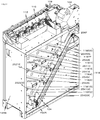
- FIG. 2 is a perspective view of the coin depositing / dispensing apparatus (no cover) according to the first embodiment of the present invention from the upper right side.
- FIG. 3 is a schematic explanatory diagram of a coin identifying device, a coin transporting device, and a coin sorting device of the coin depositing / dispensing device according to the first embodiment of the present invention.
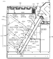
- FIG. 4 is a left side view of the coin depositing / dispensing apparatus according to the first embodiment of the present invention.
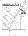
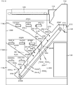
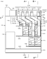
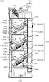
- FIG. 5 is a vertical cross-sectional view taken along the vertical surface P1 in FIG. FIG.
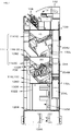
- FIG. 6 is a sectional view taken along the line AA in FIG.
- FIG. 7 is a sectional view taken along line BB in FIG.
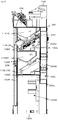
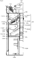
- FIG. 8 is a vertical sectional view taken along the vertical plane P2 in FIG.
- FIG. 9 is a sectional view taken along the line CC in FIG.
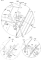
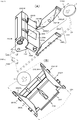
- FIG. 10 is an enlarged left side view of the coin drop prevention device of the coin depositing / dispensing device according to the first embodiment of the present invention.
- 11 is a coin fall prevention apparatus of the coin depositing / withdrawing apparatus of Example 1 which concerns on this invention, (A) is an expansion perspective view from the right side, (B) is an arrow B view in (A).
- FIG. 1 is a coin fall prevention apparatus of the coin depositing / withdrawing apparatus of Example 1 which concerns on this invention
- A is an expansion perspective view from the right side
- (B) is an arrow B view in (A).
- FIG. 12 is an operation explanatory view of the fall prevention device of the coin depositing / dispensing device according to the embodiment of the present invention.
- FIG. 13 is a vertical cross-sectional view of the coin depositing / dispensing apparatus according to the second embodiment of the present invention at the same portion as the upright plane P in FIG. 1.
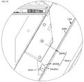
- FIG. 14 is a perspective view of the coin depositing / dispensing apparatus according to the third embodiment of the present invention from the upper left rear portion.
- FIG. 15 is a vertical cross-sectional view of the coin depositing / dispensing device according to the third embodiment of the present invention at the same portion as the upright plane P in FIG. 1.
- FIG. 13 is a vertical cross-sectional view of the coin depositing / dispensing apparatus according to the second embodiment of the present invention at the same portion as the upright plane P in FIG. 1.
- FIG. 14 is a perspective view of the coin depositing / dispensing apparatus according to the third embodiment of the present invention from the upper left rear portion.
- FIG. 16 is a sectional view of the coin depositing / dispensing device according to the third embodiment of the present invention at the same position as that of FIG. 6.
- FIG. 17 is a sectional view of the coin depositing / dispensing apparatus according to the third embodiment of the present invention at the same position as in FIG. 7.
- 18A and 18B are enlarged views of the coin drop prevention device of the coin depositing / dispensing device according to the third embodiment of the present invention.
- FIG. 18A is a perspective view
- FIG. 18B is an explanatory view at the time of locking
- FIG. It is explanatory drawing at the time of raising.
- 19A and 19B are enlarged views of the coin drop prevention device of the coin depositing / dispensing device according to the third embodiment of the present invention.
- FIG. 19A is a perspective view from the upper left side
- FIG. 19B is a perspective view from the lower right side. ..
- FIG. 20 is a perspective view from the upper left side of the coin depositing / dispensing apparatus (with cover) according to the fourth embodiment of the present invention.
- FIG. 21 is a perspective view of a coin depositing / dispensing device (without a cover) according to the fourth embodiment of the present invention as viewed from the upper right.
- FIG. 22 is a schematic explanatory diagram of a coin identifying device, a coin transporting device, and a coin allocating device of a coin depositing / dispensing device according to the fourth embodiment of the present invention.
- 23 is a vertical cross-sectional view taken along the vertical plane P2 in FIG. 24 is a cross-sectional view taken along the line AA in FIG. 25 is a sectional view taken along line BB in FIG.
- FIG. 26 is a sectional view taken along the line CC in FIG.
- FIG. 27 is a perspective view of the coin depositing / dispensing apparatus according to the fourth embodiment of the present invention, viewed from the upper left rear portion.
- FIG. 28 is a vertical cross-sectional view of the coin depositing / dispensing apparatus according to the fourth embodiment of the present invention at the same site as the upright plane P in FIG. 1.
- 29A and 29B are enlarged views of the coin drop prevention device of the coin depositing / dispensing device according to the fourth embodiment of the present invention.
- FIG. 29A is a perspective view
- FIG. 29B is an explanatory view at the time of locking
- FIG. It is explanatory drawing at the time of raising.
- FIG. 30A and 30B are enlarged views of the coin drop prevention device of the coin depositing / dispensing device according to the fourth embodiment of the present invention.
- FIG. 30A is a perspective view from the upper left side
- FIG. 30B is a perspective view from the lower right side. ..
- the coin sorting device After discriminating the coins inserted into the deposit port by the coin discriminating device, the coin sorting device linearly extends in the direction away from the deposit port and transfers the coins one by one while the coin sorter sorts the coins into a plurality of coin types. After that, the coins are arranged in a plurality of stages in the vertical direction and guided to a plurality of denomination holding and feeding devices arranged along the coin conveying device by a denomination dropping passage arranged on one side of the coin conveying device. Based on the withdrawal command, from the outlet of the denomination-type holding and feeding device to the payout passage arranged on the other side of the coin transporting device, one by one, along the row of the denomination-type holding and feeding device.
- a coin depositing / dispensing device for dropping onto a dispensing conveyor belt arranged in a manner and sending it to a dispensing outlet arranged in the vicinity of the depositing opening by running of the dispensing conveyor belt, wherein the dispensing passage is at least , A bottom surface of the dispensing path, which has a slanting plate that slopes downward to the dispensing port side and a coin that falls from the delivery port slides down, and the dispensing conveyor belt has a part of the lower end of the slanting plate.
- the coin depositing / dispensing device is characterized in that it is arranged below the coin and is inclined upward toward the dispensing port. Accordingly, it is possible to provide a coin depositing / dispensing device capable of smoothly collecting coins without clogging during a collecting operation for simultaneously collecting and collecting coins fed out from the denomination-type holding and feeding device.
- the embodiment for carrying out the present invention is to drop the coins fed out from the coin holding and feeding device arranged in a plurality of rows in the horizontal direction onto the lifting belt inclined forward toward the next process side,
- a coin hoisting device for sending out to the next process side by traveling of a sending belt at least, Above the lifting belt, an upper end portion is rotatable about an axis extending in a direction substantially orthogonal to a traveling direction line of the lifting belt, and a lower end portion of the lifting belt is the uppermost portion with respect to an upper surface of the lifting belt.
- a protrusion provided on the lifting belt including a protrusion for rotating the fall prevention body while pushing the falling stopper to the downstream side in the longitudinal direction of the lifting belt by moving the lifting belt in the coin lifting direction;
- the drop blocker blocks coins falling on the lifting belt at the blocking position on the downstream side surface in the longitudinal direction of the lifting belt, and is pushed by the protrusion from the upstream side surface in the longitudinal direction of the lifting belt to block the coins.
- a coin lifting device characterized by flipping a coin upward in a lifting belt.
- the coin depositing / dispensing apparatus 100 will be described with reference to FIGS. 1 to 12.
- the first embodiment is a coin depositing / dispensing device 100 for euro coins, and includes 2 cent coins, 5 cent coins, 10 cent coins, 20 cent coins, 1 cent coin, 2 euro coins, 50 cent coins, and 1 euro coins.
- Japanese coins, US coins, etc. can be handled.
- the coin depositing / dispensing device 100 is used as an automatic coin depositing / dispensing device alone in a bank or a retail store, or is used in combination with a bill depositing / dispensing device, a credit card / debit card processing machine, or the like.
- the coin depositing / dispensing device 100 at least, the coin separating / delivering device 104 that separates and sends out the coins C received in the deposit port 102 in the form of roses, and the authenticity and denomination of the coin C.
- a dispensing and transporting belt 124 that transports the mouth 122.
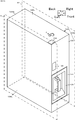
- the coin depositing / dispensing apparatus 100 is formed in an elongated cubic shape by a cover 126 that covers the left side plate 128L, the right side plate 128R, the upper plate 128U, and the rear side plate 128B among the roughly rectangular main body 126 and the outer surface of the main body 126. ing.
- a vertically long right space 132R is defined by an inner right wall plate 130R vertically arranged in the width direction when viewed from the front side in the width direction.
- a vertically-extending left space 132L and a vertically-extending central space 132M which is wider than the right space 132R and the left space 132L, are defined by the inner left wall plate 130L vertically arranged on the left side.
- a part of the denomination-type drop passage 116 is arranged in the right space 132R, a withdrawal passage 118 is arranged in the left space 132L, and a denomination holding suspension device 114 is arranged in the central space 132M.
- a rectangular withdrawal opening 122 is formed in the upright front surface of the main body 126 at an intermediate portion in the vertical direction. Below the dispensing port 122, a mounting hole 142 for a removable coin container 138 is formed in the lower part of the main body 126.
- the coin container 138 stores all coins C when all coins are collected.
- a coin receiving port 102 for a rectangular coin C is formed upward.
- the main body 126 has a function in which the above-mentioned main device is built-in or attached, and is configured by a sheet metal into a substantially vertical cubic shape.
- the top plate 1281 and the upper bottom plate are installed approximately horizontally.
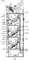
- 1282, a middle bottom plate 1283, a lower bottom plate 1284, an inner bottom plate 1285, and a bottom plate 1286 are vertically divided into four layers. That is, an upper space 144U is formed between the top plate 1281 and the upper bottom plate 1282, an intermediate space 144M is formed between the upper bottom plate 1282 and the middle bottom plate 1283, and a lower space 144L is formed between the middle bottom plate 1283 and the lower bottom plate 1284. .
- a bottom space 144B is formed between the inner bottom plate 1285 and the bottom plate 1286.
- the upper space 144U, the middle space 144M, and the lower space 144L are arranged below the deposit port 102 and extend linearly horizontally in the direction away from the deposit port 102, and their height and width are the same. Has been formed.
- the coin transfer device 108 and the coin sorting device 112 that are integrated are installed on the top plate 1281. Further, as shown in FIG. 9, above the central space 132M which is the center of the top plate 1281 in the width direction, a 1-cent opening for dropping a 1-cent coin is formed in a roughly square shape in order from the deposit port 102 side.
- the deposit port 102 has a function of receiving a plurality of coins C collectively and guiding the coins to the coin separating and delivering device 104.
- the deposit port 102 is an upward rectangular opening formed on the front upper surface of the main body 126.
- a guide tube 146 (FIG. 3) is formed to extend obliquely downward from the front side to the rear side of the deposit port 102, and the lower end of the guide tube 146 is located on the upper opening of the bowl-shaped coin storage container 148 that constitutes the coin separating and delivering device 104. It is open. Therefore, the plurality of coins C inserted into the deposit port 102 are guided by the guide tube 146 and fall into the coin storage container 148 of the coin separating and delivering device 104.
- the coin separation / delivery device 104 has a function of separating coins C of plural denominations with different diameters held in a separated state one by one and sending them to the coin discriminating device 106 which is the next step.
- a delivery device is used.
- the coin separating / delivering device 104 of the first embodiment is arranged below the deposit port 102, and includes a rotating disk 152, a coin storage container 148, a receiving body 154, and a full sensor 156.
- the rotating disk 152 has a receiving portion 168 for receiving the coins C one by one, is inclinedly arranged at a predetermined angle, and is rotated at a predetermined speed.
- a Y-shaped plate 164 in which three concave portions 162 are formed on the upper surface of the rotary disc 152 at equal intervals is fixed concentrically with the rotary disc 152.
- An extrusion body 166 that pivots is disposed on one side of the recess 162 (see, for example, Japanese Patent No. 4997374). In other words, the extrusion body 166 and the recess 162 form a substantially semicircular receiving portion 168.
- the receiving portion 168 is set to a size such that two minimum diameter coins cannot be received side by side and only one maximum diameter coin can be received.
- the extruded body 166 is normally positioned in a stationary state at a position closer to one side of the concave portion 162 so as to form the receiving portion 168, and when it is pivotally moved to a predetermined position, the held coin C is rotated. It is sent out in the circumferential direction of the disc 152.
- the receiving portion 168 receives the coins C held in a loose state one by one in the lower portion facing the coin storage container 148, and the push-out body 166 has the receiving portion 168 at a predetermined position above the center of rotation of the rotating disc 152.
- the coin C is extruded in the circumferential direction and delivered to the knife-shaped receiver 154.
- the rotating disk 152 is rotated at a predetermined speed by an electric motor (not shown) via a speed reducer.
- the full sensor 156 has a function of outputting a full signal when the amount of coins in the coin storage container 148 exceeds a predetermined amount, and is, for example, a transmissive photoelectric sensor.
- a transmissive photoelectric sensor When the full sensor 156 outputs a full signal, the acceptance of the coin C from the deposit port 102 is restricted by means not shown, and when the full signal is not output, the acceptance restriction of the coin C is released.
- the coin discriminating device 106 acquires physical property information of the coin C sent out by the coin separating and sending device 104, surface pattern information or the like by a sensor, and performs authenticity determination based on the acquired information, and a function of performing denomination determination.
- a publicly known coin discriminating device is used.
- the coin identifying device 106 includes a magnetic sensor 174, a slide base (not shown) arranged in the same plane as the upper surface of the rotating disc 152, a rotating body 176 for feeding the coin C, and a reference guide 178. Is included.
- the slide base (not shown) has a function of guiding one surface of the coin C pushed by the rotating body 176.
- the rotator 176 has a function of moving the coins C received from the coin separating and delivering device 104 and passing them one by one through the coin receiving portion 182. Further, the rotating body 176 has a function of transferring the coin C that has passed through the coin receiving portion 182 to the coin transfer device 108.
- the rotating body 176 is parallel to the slide base and is rotatable in a plane close to the slide base, and the coin receiving portion 182 is moved by three push levers 184 arranged at equal intervals as the receiving portion 168. Formed and have a Y shape.
- the reference guide 178 has a function of linearly guiding the coin C passing through the coin receiving portion 182 and keeping the position of the coin C relative to the magnetic sensor 174 constant.
- the known coin discriminating device 106 it is preferable to use the coin discriminating device disclosed in Japanese Patent No. 4997374, but the present invention is not limited to this.
- the coin transfer device 108 has a function of linearly transferring the coins C sent out one by one from the coin identification device 106 in a direction away from the deposit port 102.
- the coin transporting device 108 of the first embodiment is integrated with a coin sorting device 112, which will be described later, and is fixed on the top plate 1281.
- An endless carrier 186 that moves in one direction away from the deposit port 102 in the same plane, a slide plate 188 on which one surface of the coin C pushed by the endless carrier 186 slides, and a straight line that guides the peripheral surface of the coin C. It includes a guide rail 192 in the shape of.
- the endless carrier 186 is a chain 198 stretched substantially horizontally between the first sprocket 194 and the second sprocket 196 arranged at a predetermined interval.
- the chain 198 is installed in the shape of a flat running track, and the first sprocket 194 is arranged immediately to the side of the rotating body 176 of the coin identifying device 106.
- Pushing pins 202 are fixed to the side surface of the chain 198 at predetermined intervals.
- a plurality of push pins 202 are attached to the chain 198 at intervals corresponding to the intervals of the push levers 184.
- the first sprocket 194 is rotated at a predetermined speed, and the push lever 184 and the push pin 202 immediately push the coin C pushed by the push lever 184 to the transfer path 204 of the push pin 202. Is set to push.
- the transfer path 204 is a path along which the coin C, which is pushed by the push pin 202 while being guided by the guide rail 192, moves.
- the guide rail 192 has a function of guiding the lower end peripheral surface of the coin C so that the coin C pushed by the pushing pin 202 moves along the transfer path 204.
- the guide rail 192 is disposed along the running track-shaped upper linear chain 198 and slightly below the chain 198.
- the guide rail 192 protrudes slightly in a direction orthogonal to the slide plate 188 from the maximum thickness of the handling coin C. Therefore, the lower surface of the coin C pushed by the push pin 202 is guided by the slide plate 188, and the lower end peripheral surface is guided by the guide rail 192.
- the guide rail 192 in the first embodiment also serves as a sorting unit, as described later.
- the coin transporting device 108 it is preferable to use the coin transporting device disclosed in Japanese Patent No. 4997374, but the present invention is not limited to this.
- the coin sorting device 112 has a function of dropping the coins C conveyed by the coin conveying device 108 into coin selection holes of a corresponding denomination based on the identification denomination in the coin identifying device 106 and allocating the coins for each predetermined denomination.
- the coin sorting device 112 according to the first embodiment includes an upper sorting unit 206 arranged along the guide rail 192 on the upper side of the guide rail 192 and a lower sorting unit arranged on the lower side along the guide rail 192. Has 208.
- the upper sorting unit 206 sequentially sorts the 2 cent sorting hole 2C, the 5 cent sorting hole 5C, the 10 cent sorting hole 10C, and the 20 cent sorting hole toward the traveling direction of the coin transporting device 108, in other words, in the direction away from the deposit port 102.
- the hole 20C and the overflow selection hole OF are arranged.
- the lower sorting unit 208 sorts the reject sorting hole RJ, the 1-cent sorting hole 1C, the 2-euro sorting hole 2E, the 50-cent sorting in the order of moving in the coin transport device 108, that is, the direction away from the deposit port 102.
- Hole 50C and 1 euro selection hole 1E are located. Note that the arrangement of the denominations for each coin selection hole is an example, and can be freely arranged as necessary.
- a gate device (not shown) operated by an electric actuator is arranged in each coin sorting hole 2C, 5C, 10C, 20C, OF, 224, RJ, 1C, 2E, and 50C.
- the gate device for the coin sorting holes RJ, 1C, 2E, and 50C also serves as the guide rail 192. That is, the guide rail 192 is composed of a fixed guide fixed between the coin selection holes RJ, 1C, 2E, or 50C and a movable guide that is electrically driven, and usually has a single linear shape. There is.
- the movable guide is moved from the normal position so that the transferred coin C is not guided by the movable guide. , The coin is dropped into a predetermined coin selection hole (see Japanese Patent No. 4997374).
- the gate device facing each coin sorting hole 2C, 5C, 10C, 20C, OF, 224, RJ, 1C, 2E, or 50C is provided with a timing signal from a timing sensor (not shown) and a coin discriminating device 106. It is selectively opened or closed based on the authenticity and denomination discriminated by the detected coin information. As a result, the coin C transported by the coin transport device 108 is dropped into the predetermined coin sorting holes 2C, 5C, 10C, 20C, OF, 224, RJ, 1C, 2E, or 50C for each denomination.
- the denomination holding operation device 114 has a function of holding the coins C sorted by denomination in the coin allocating device 112 for each denomination, and a command from a higher-level device, for example, a POS cash register, a coin of a predetermined denomination It has a function of paying out a predetermined number of Cs one by one.
- a higher-level device for example, a POS cash register
- 8 denomination holding suspension operation devices 114 are arranged, but the basic configurations are the same.
- the denomination-type holding and feeding device 114 is generally constituted by a hopper bowl 236, a rotary body 238 with a hole, a slide base 242, and an ejecting device (not shown).
- the hopper bowl 236 is a vertically oriented cylindrical body having an open upper surface and a rectangular upper portion and a circular lower portion, and holds the coins C in bulk.
- the holed rotating body 238 is rotatably arranged in a circular hole at the bottom of the hopper bowl 236, and a plurality of circular holes through which the coin C falls are formed at eccentric positions.
- the slide base 242 guides the lower surface of the coin C dropped on the rotating body 238 with a hole.
- the ejection device (not shown) is composed of an ejection roller biased to approach a fixed roller arranged on the side of the holed rotary member 238, and the coin C pushed out by the holed rotary member 238 is pushed. Is sandwiched between these rollers and is ejected laterally from an outlet 244 formed on the side of the rotary body 238 with holes. It is preferable to use a so-called coin hopper as the denomination holding operation device 114.
- the denomination reserve operation device 114 has three denominations arranged in the upper space 144U, three denominations in the middle space 144M, and two denominations in the lower space 144L. Specifically, on the upper bottom plate 1282, in order from the deposit port 102 side, by placing 1 cent holding operation device 1141C, 2 euro holding operation device 1142E, and 50 cent holding operation device 11450C, It is arranged in the upper space 144U and constitutes the upper holding operation device row 114U.
- a 2 cent holding operation device 1142C, a 5 cent holding operation device 1145C, and a 1 euro holding operation device 1141E are arranged in this order from the deposit port 102 side to form a middle holding operation device row 114M. is doing.
- a 10-cent holding and feeding device 11410C and a 20-cent holding and feeding device 11420C are arranged in this order from the deposit port 102 side to configure a lower holding and feeding device array 114L.
- the 1-euro holding operation device 1141E in the middle space 144M and the 20-cent holding operation device 11420C in the lower space 144L are arranged in the vicinity of the rear side plate 128B and are vertically aligned.
- the 1 euro holding operation device 1141E in the middle space 144M and the 20-cent holding operation device 11420C in the lower space 144L are arranged in the central space 132M farthest from the deposit port 102.
- the 5-cent reserve operation device 114SC in the middle space 144M and the 10-cent reserve operation device 11410C in the lower space 144L are vertically aligned.
- the 5-cent holding operation device 114SC in the middle space 144M and the 10-cent holding operation device 11410C in the lower space 144L are arranged in the central space 132M that is the second farthest from the deposit port 102.
- the 50 cent holding operation device 11450C, the 2 euro holding operation device 1142E, and the 1 cent holding operation device 1141C are the 1 euro holding operation device 1141E and the 5 cent holding operation device 1145C, 2 in the middle space 144M. It is displaced toward the deposit port 102 side with respect to the cent hold operation device 1142C. This is because the denomination-specific drop passage 116 is disposed between the rear side plate 128B and the rear side plate 128B.
- the denomination type drop passage 116 has a function of guiding the coins C sorted by denomination by the coin sorting device 112 to the denomination holding device 114 for each denomination.
- the denomination-type drop passage 116 is formed in a cylindrical shape that extends in the vertical direction, and the upper drop passage 116U arranged on the upper side of the top plate 1281 and the lower fall path of the top plate 1281. And a lower drop passage 116L.
- the 1 cent sorting hole 1C, the 2 euro sorting hole 2E, the 50 cent sorting hole 50C formed in the lower sorting portion 208, and the denomination drop passage 116 corresponding to the 1 euro sorting hole 1E are the top plate 1281. It is configured only by the upper drop passage 116U on the upper side.
- the denomination-type drop passage 116 for the 1-cent reserve operation device 1141C, the 2-euro retention operation device 1142E, and the 50-cent reserve operation device 11450C arranged in the upper space 144U will be described. As shown in FIG.
- a return money type drop passage 116RJ is formed below the return selection hole RJ closest to the deposit port 102 of the lower sorting unit 208 in the coin sorting device 112, and the returned coin C is output.
- the 1-cent coin C dropped from the 1-cent sorting hole 1C closest to the deposit port 102 is guided to the 1-cent drop passage 1161C and dropped into the 1-cent opening 1461C shown in FIG. 9, and then placed in the upper space 144U. It is held in the 1st cent holding operation device 1141C.
- the 2 euro coin C dropped from the 2 euro selection hole 2E closest to the deposit port 102 is guided to the 2 euro drop passage 1162E, dropped to the 2 euro opening 1462E shown in FIG.
- the 50-cent coin C dropped from the 50-cent selection hole 50C closest to the deposit port 102 is guided to the 50-cent drop passage 11650C, dropped to the 50-cent opening 14650C, and then retained in the upper space 144U for a 50-cent reserve.
- the 1 euro coin C dropped from the 1 euro selection hole 1E closest to the 5th deposit port 102 is guided to the 1 euro drop passage 1161E and dropped to the 1 euro opening 1461E, and then the farthest from the deposit port 102 of the middle space 144M. It is held in the 1-euro holding operation device 1141E arranged at the position.
- the 1-euro holding operation device 1141E is arranged in the middle space 144M, the 1-euro drop passage 1161E is divided into a 1-euro upper drop passage 116U1E and a 1-euro lower drop passage 116L1E.
- the 1 euro lower drop passage 116L1E is juxtaposed in the lateral width direction of the main body 126 with respect to an overflow safe 134 described later.
- the 2-cent sorting hole 2C, the 5-cent sorting hole 5C, the 10-cent sorting hole 10C, the 20-cent sorting hole 20C, and the overflow sorting hole OF arranged in the upper sorting section 206 are provided with a ceiling plate 1281
- the upper drop passage 116U on the upper side and the lower drop passage 116L on the lower side of the top plate 1281 are separated from each other.
- the 2 cent coin C dropped from the 2 cent sorting hole 2C closest to the deposit port 102 is guided to the 2 cent upper drop passage 116U2C, dropped to the 2 cent opening 1462C, and then guided to the 2 cent lower drop passage 116L2C. It is reserved in the 2-cent reserve operation device 1142C arranged in the middle space 144M.
- the 5 cent coin C dropped from the 5 cent sorting hole 5C which is the second closest to the deposit port 102, is guided to the 5 cent upper drop passage 116U5C, dropped into the 5 cent opening 1465C, and then placed in the middle space 144M. It is guided to the lower drop passage 116L5C and is held in the 5-cent holding operation device 1145C.
- the 10-cent coin C dropped from the 10-cent sorting hole 10C closest to the deposit port 102 is guided to the 10-cent upper drop passage 116U10C, dropped to the 10-cent opening 14610C, and then guided to the 10-cent lower drop passage 116L10C. Then, it is held in the 10-cent holding operation device 11410C arranged in the lower space 144L.
- the 20-cent coin C dropped from the 20-cent sorting hole 20C closest to the deposit port 102 is guided to the 20-cent upper drop passage 116U20C, dropped to the 20-cent opening 14620C, and then guided to the 20-cent lower drop passage 116L20C. Then, it is held in the 20-cent holding operation device 11420C arranged in the lower space 144L.
- Fifth, the overflow coin C that has fallen from the overflow selection hole OF near the deposit port 102 is guided to the overflow upper drop passage 116UOF, drops to the overflow opening 146OF, and is then retained in the overflow safe 134 arranged in the upper space 144U. To be done.
- the overflow coin C can be arranged outside the cover 128.
- the two-cent lower drop passage 116L2C, the five-cent lower fall passage 116L5C, the ten-cent lower fall passage 116L10C, and the twenty-cent lower fall passage 116L20C are the two-cent opening 1462C, five-cent opening 1465C, ten-cent opening 14610C, and After the 20-cent opening 14620C, the cross-section is formed into a rectangular shape having a narrow horizontal width and long in the transport direction of the coin C, and the rectangles are arranged side by side in the right space 132R in a direction away from the deposit port 102.
- the two-cent lower drop passage 116L2C, the five-cent lower drop passage 116L5C, the ten-cent lower drop passage 116L10C, and the twenty-cent lower drop passage 116L20C are provided on the right side plate 128R forming the cover 128. It is configured by being integrated. Therefore, when a coin jam occurs in these passages, the coin jam can be easily eliminated by removing the right side plate 128R and working. Further, by forming the coin-type drop passage 116 in this manner, a plurality of coin drop passages can be arranged in the same thin space in the width direction of the main body, which is advantageous in that the device can be downsized.
- the two-cent lower drop passage 116L2C and the five-cent lower drop passage 116L2C are arranged in the middle space 144M in the order away from the deposit port 102.
- it In order to guide each coin C to the holding feeding device 1145C, it is formed in a crank shape, and the lower ends thereof are opposed to the upper ends of the left (front) side end openings of the hopper bowls 236 of the corresponding holding feeding devices. It is arranged.
- the 10-cent lower drop passage 116L10C and the 20-cent lower drop passage 116L20C are arranged in the lower space 144L in order in the direction away from the deposit port 102.
- the coins C In order to guide the coins C to the 11420C respectively, they are formed in a crank shape, and their lower ends are arranged opposite to the upper end of the right (rear) side end opening of the hopper bowl 236 of the corresponding holding feeding device. .
- the denomination-type drop passages 116 By arranging the denomination-type drop passages 116 in this manner, the bending of the denomination-type drop passages 116 can be reduced, and the denomination-type drop passages 116 through which the coins C can smoothly fall can be configured in a narrow space.
- the withdrawal passage 118 has a function of guiding and dropping the coin C sent out from the denomination type holding and feeding device 114.
- the dispensing passage 118 is a left side space 132L formed between the left side plate 128L and the inner left side wall plate 130L.
- a plurality of horizontally elongated rectangular denomination drop ports 252 through which the coins C sent out from the denomination-type holding and feeding device 114 pass are formed in the inner left side wall plate 130L that constitutes the payout passage 118.
- the drop ports 252 of denominations are also formed in three stages in parallel in the horizontal direction.
- the 1-cent drop port 2521C, the 2-euro drop port 2522E, and the 50-cent drop port 25250C are horizontally arranged in order from the deposit port 102 side. It is formed along 108 and constitutes the upper paragraph lower mouth row 252U.
- a 2-cent drop port 2522C, a 5-cent drop port 2525C, and a 1-euro drop port 2521E are formed horizontally along the coin transfer device 108 from the deposit port 102 side. It constitutes the lower paragraph row 252M in the middle paragraph.
- a 10-cent drop port 25210C and a 20-cent drop port 25220C are horizontally formed along the coin transfer device 108, and the lower paragraph lower port row 252L is formed. I am configuring.
- these drop ports 252 are also vertically aligned with the middle paragraph lower mouth row 252M and the lower paragraph lower mouth row 252L.
- the middle paragraph lower mouth row 252M and the upper paragraph lower mouth row 252U are arranged to be offset in the front-rear direction.
- the withdrawal passage 118 is composed of an upper withdrawal passage 118U for the upper paragraph lower outlet row 252U, an intermediate withdrawal passage 118M for the middle paragraph lower outlet row 252M, and a lower withdrawal passage 118L for the lower paragraph lower outlet row 252L.
- the upper-stage dispensing passage 118U, the middle-stage dispensing passage 118M, and the lower-stage dispensing passage 118L are arranged closer to the rear side in the front-rear direction of the main body 126.
- the upper-stage dispensing passage 118U is a space that is surrounded by the top plate 1281, the left side plate 128L, the inner left side wall plate 130L, and the upper-side inclined plate 254U and has an inverted triangular shape in a side view.
- the upper sloping plate 254U constitutes the bottom surface of the upper withdrawal passage 118U, and inclines downward toward the withdrawal outlet 122 side at an angle at which coins dropped from the lower paragraph row 252U in the upper paragraph slide down.
- the inclination angle of the upper sloping plate 254U is preferably 35 ° to 45 ° with respect to the horizontal line, and the lower end of the upper sloping plate 254UL, which is the lower end of the upper sloping plate 254U, is arranged at the center of the main body 126 in the vertical direction and the front-back direction.
- the lower end 254UL of the upper sloping plate is arranged below the rear end of the 1-cent drop port 2521C. Therefore, the coin C dropped from the 1-cent drop opening 2521C forming the upper paragraph lower opening row 252U drops on the withdrawal transfer belt 124, which will be described later, through the upper-stage withdrawal passage 118U, and the 2 euro drop opening 2522E and 50 cents.
- the coin C that has dropped from the drop port 25250C passes through the upper dispensing path 118U and drops onto the upper sloping plate 254U, and then slides down on the upper sloping plate 254U and onto the dispensing conveyor belt 124 from the lower end 254UL of the upper sloping plate. Fall to.
- the middle-stage dispensing passage 118M is an inverted trapezoidal space in a side view, which is surrounded by the upper sloping plate 254U, the left side plate 128L, the inner left side wall plate 130L, and the middle sloping plate 254M.
- the middle sloping plate 254M constitutes the bottom surface of the middle withdrawal passage 118M, and is inclined downward toward the withdrawal outlet 122 side at an angle at which the coin C dropped from the middle paragraph lower outlet row 252M slides down.
- the middle sloping plate 254M is inclined parallel to the upper sloping plate 254U, and the lower end of the middle sloping plate 254ML, which is the lower end of the middle sloping plate 254M, is disposed below and behind the upper sloping plate lower end 254UL. With this configuration, the lower end 254ML of the middle sloping plate is disposed below the 2-cent drop port 2522C and the 5-cent drop port 2525C.
- the coin C dropped from the 2-cent drop port 2522C forming the lower paragraph row 252M in the middle paragraph drops on the withdrawal transfer belt 124, which will be described later, through the middle stage withdrawal passage 118M, and the 1 euro drop ports 2521E, and 5
- the coin C dropped from the cent drop port 2525C passes through the middle payout passage 118M and drops onto the middle tilted plate 254M, and then slides down on the middle tilted plate 254M and the withdrawal conveyor belt 124 from the middle tilted plate lower end 254ML. Fall on top.
- the lower-stage dispensing passage 118L is an inverted trapezoidal space in a side view, which is surrounded by the middle sloping plate 254M, the left side plate 128L, the inner left side wall plate 130L, and the lower sloping plate 254L.
- the lower sloping plate 254L constitutes the bottom surface of the lower withdrawal passage 118L, and is inclined downward toward the withdrawal opening 122 side at an angle at which the coins C dropped from the lower paragraph lower opening row 252L slide down.
- the lower sloping plate 254L is inclined parallel to the middle sloping plate 254M, and the lower end of the lower sloping plate lower end 254LL, which is the lower end of the lower sloping plate 254L, is arranged below and behind the middle sloping plate lower end 254ML.
- the lower end 254LL of the lower sloping plate is arranged below the rear end of the 10-cent drop opening 25210C. Therefore, the coin C dropped from the 10-cent drop opening 25210C forming the lower paragraph row 252L in the lower paragraph passes through the lower-stage dispensing passage 118L and drops onto the withdrawal conveyor belt 124 or the lower-side sloping plate lower end 254LL described below, and drops by 20 cents.
- the coin C dropped from the mouth 2525C passes through the lower payout passage 118L and drops onto the lower sloping plate 254L, and the coin C slides down and drops from the lower end 254LL of the lower sloping plate onto the withdrawal conveying belt 124.
- the upper-stage dispensing passage 118U, the middle-stage dispensing passage 118M, and the lower-stage dispensing passage 118L are arranged in a vertically stacked state in the left space 132L.
- the width of the dispensing passage 118 (the distance between the right guide plate 264R and the left guide surface 264GL) is preferably about twice the maximum diameter coin diameter. In Example 1, the maximum diameter is 25.75 mm of a 2-euro coin, so it is preferably doubled to about 50 mm.
- the withdrawal conveyor belt 124 is sent out from the withdrawal device 114 for denomination classification, and positions the coin C dropped from the withdrawal passage 118 (upper withdrawal passage 118U, middle withdrawal passage 118M, lower withdrawal passage 118L) upward. It has a function of conveying to the dispensing port 122.
- the withdrawal transfer belt 124 is configured by the withdrawal transfer belt 124 wound between the front withdrawal transfer roller 256F and the withdrawal transfer roller 256B.
- the pay-out transfer belt 124 has a flat track field shape by a front pay-out transfer roller 256F and a rear pay-out transfer roller 256B, and is inclined upward toward the pay-out port 122 side.
- the post-payout transfer roller 256B is located below the lower sloping plate lower end 254LL, and is arranged slightly on the front side. In height, it is arranged above the front outlet port 122.
- the conveying unit 258 of the dispensing conveyor belt 124 is linearly forward (extended from the lower end of the upper sloping plate 254UL, the lower end of the middle sloping plate 254ML, and the lower end of the lower sloping plate 254LL, at the same distance as the lower end thereof. It extends in an upwardly inclined state toward the gold mouth 122 side).
- the upward inclination is preferably inclined by 45 degrees or more with respect to the horizontal line, and more preferably about 60 degrees from the viewpoint of the installation area and the coin C carrying capacity.
- the upward inclination angle of the pay-out transfer belt 124 toward the pay-out port 122 side can be appropriately set in consideration of the influence on the size of the coin pay-in / pay-out device 100 in the depth direction.
- Plate-shaped projections 262 are formed on the surface of the dispensing conveyor belt 124 at right angles to the dispensing conveyor belt 124 at predetermined intervals in the longitudinal direction of the dispensing conveyor belt 124.
- the interval between the protrusions 262 is preferably the same as the interval between the fall prevention devices 264, which will be described later, between the lower end 254UL of the upper sloping plate and the lower end 254ML of the middle sloping plate.
- the protrusion 262 is configured by being divided into a right protrusion 262R and a left protrusion 262L in the width direction of the dispensing conveyor belt 124, and arranged in parallel at a predetermined interval.
- an upward delivery passage 266 is formed by a left guide plate 264L and a right guide plate 264R arranged in parallel at a predetermined interval in the width direction of the main body 126. Is configured.
- the transport passage 266 has a function of guiding the coins C conveyed by the withdrawal transfer belt 124, and in the first embodiment, the withdrawal transfer belt 124 (flat belt) constitutes the bottom surface, and the left guide plate 264L and the right guide plate 264R. Constitute the left and right guide surfaces.
- the transport passage 266 has the transport portion 258 of the dispensing transport belt 124 as the bottom face, and extends toward the dispensing port 122 having a rectangular cross section by the left guide plate 264L and the right guide plate 264R that stand upright with respect to the bottom face. And has a groove shape extending obliquely.
- a fall prevention plate 268 is arranged so as to close the entire rectangular cross section of the transport passage 266.
- a drop prevention device 264 is arranged in the transport passage 266.
- the drop prevention device 264 has a function of preventing the coin C sent to the upper dispensing path 118 from falling to the lower dispensing path 118 side in the transport passage 266.
- the coin C sent to the upper-stage dispensing passage 118U has a function of preventing the coin C from falling into the middle-stage dispensing passage 118M in the transport passage 266.
- the drop prevention device 264 prevents the coin C sent from the upper holding operation device row 114U to the upper withdrawal passage 118U from dropping to the lower middle withdrawal passage 118M side in the transfer passage 266.
- the conveying passage 266 is configured such that the upper conveying passage 266U is formed above the upper paragraph lower blocking device 2641, and the middle conveying passage is provided between the upper paragraph lower blocking device 2641 and the middle paragraph lower blocking device 2642.
- 266M is configured, and a lower stage transport passage 266L is formed below the middle paragraph lower blocking device 2642.
- the upper paragraph lower blocking device 2641 and the middle paragraph lower blocking device 2642 have the same configuration, the upper paragraph lower blocking device 2641 will be described as a representative.
- the upper paragraph lower blocking device 2641 includes a guide body 264G and a blocking body 264S.
- the guide body 264G has a function of forcibly guiding the coin C falling downward along the withdrawal conveying belt 124 through the upper dispensing path 118U to the blocking body 264S side.
- the guide body 264G is formed in a V shape by the right guide surface 264GR and the left guide surface 264GL that widen toward the dispensing port 122 side.
- the V-shaped apex 264GT is formed above the right protrusion 262R, being biased toward the central space 132M side in the width direction of the dispensing conveyor belt 124. Therefore, the coin C is guided by the right guide surface 264GR and the left guide surface 264GL and finally guided to the right protrusion 262R.
- the apex 264GT can be formed so as to face the left protrusion 262L.
- the blocking body 264S has a function of blocking the coin C sent to the upper-stage dispensing passage 118U in the upper-stage transport passage 266U so as not to drop toward the lower middle-stage dispensing passage 118M.
- the blocking body 264S is made of a block of hard resin, hard rubber, metal, or the like, the upper end of which is fixed to the lower end of the guide body 264G.
- the lower surface of the blocking body 264S is formed to a convex surface 264SC that bulges toward the conveying unit 258 side, and a part of the blocking body 264S is arranged in contact with or in the vicinity of the conveying unit 258 of the pay-out conveying belt 124, and between the pay-out conveying belt 124 and the convex surface 264SC. It is configured so that the coin C does not drop from the space.
- a left groove 264SL and a right groove 264SR are formed facing the protrusion 262 (the right protrusion 262R, the left protrusion 262L), and the right protrusion 262R and the left protrusion 262R that move integrally with the withdrawal transfer belt 124 are formed. It is configured so that the protrusion 262L can pass through. With this configuration, the coin C that has dropped into the upper-stage dispensing passage 118U is prevented from falling into the middle-stage conveying passage 266M by the upper-stage lower blocking device 2641, specifically, the blocking body 264S.
- the coin C which has been prevented from falling, is locked by the right protrusion 262R or the left protrusion 262L and is sent to the dispensing port 122 side.
- the middle paragraph lower blocking device 2642 also functions in the same manner, and prevents the coin C from dropping from the middle transport passage 266M to the lower transport passage 266L.
- the withdrawal port 122 has a function of withdrawing to an external device to transfer the coin C conveyed by the withdrawal conveyor belt 124 or holding the coin C in the main body 126, and a known withdrawal port 122 is used.
- the dispensing port 122 is a rectangular opening formed near the left side of the front surface of the main body 126 in the vertical middle.
- a downward dispensing port passage 272 is formed toward the dispensing port 122 following the upper-stage transport passage 266U facing the dispensing port belt 124, and at the end of the dispensing port passage 272,
- the dispensing port 122 is configured and is supplied from the dispensing port 122 to an external receiving unit.
- the coin container 138 has a function of storing the coin C sent from the denomination-type holding and feeding device 114, and is a mounting hole formed in the main body 126 below the deposit port 102 and the dispense port 122. It is stored in 142.
- the coins C are lifted by the dispensing conveyor belt 124 Send it out to the gold mouth 122.
- a switching plate 274 is arranged in the middle of the dispensing port passage 272.
- the switching plate 274 is held at the dispensing position PP that constitutes the bottom plate of the dispensing port passage 272 when dispensing to the dispensing port 122. However, at the time of collecting the coin C, the switching plate 274 is moved to the collecting position RP in which the coin jumps up, closing the withdrawal opening passage 272 and opening a passage connected to the upper opening of the coin container 138. As a result, the coins C that are lifted up by the dispensing and conveying belt 124 are guided by the switching plate 274 and collected in the coin container 138.
- the coin C sent from the upper-stage holding and feeding device row 114U arranged in the upper row is the 1-cent drop outlet 2521C, the 2-euro drop outlet 2522E, or the 50-cent drop outlet of the upper paragraph lower mouth row 252U.
- Each of them passes through the 25250C and drops in the upper-stage dispensing passage 118U, and then drops onto the upper-stage inclined plate 254U or onto the dispensing conveying belt 124.
- the coin C dropped on the upper sloping plate 254U slides on the upper sloping plate 254U, and then drops on the dispensing and conveying belt 124.
- the distance between the upper paragraph lower mouth row 252U and the upper sloping plate 254U, or the withdrawal transfer belt 124 is small, and even if the coin C that has fallen onto them jumps, the amount is small, and it fits in a short time, and the withdrawal transfer is performed. It is locked by the protrusion 262 on the belt 124 and is conveyed toward the dispensing port 122.
- the coins C sent out from the 2 cent drop opening 2522C, the 5 cent drop opening 2525C, or the 1 euro drop opening 2521E of the middle stage holding and feeding device row 114M arranged in the middle row pass through the middle paragraph lower row 252M respectively.
- the withdrawal passage 118M falls, and drops onto the middle sloping plate 254M or onto the withdrawal conveyor belt 124.
- the coin C dropped on the middle sloping plate 254M slides on the middle sloping plate 254M, and then drops on the pay-out transfer belt 124.
- the distance between the middle paragraph lower mouth row 252M and the middle sloping plate 254M or the withdrawal conveyor belt 124 is small, and even if the coin C dropped on them jumps, the amount is small, it fits in a short time, and the withdrawal occurs. It is locked to the protrusion 262 on the conveyor belt 124 and conveyed toward the dispensing port 122.
- the distance between the lower paragraph row 252L and the lower sloping plate 254L, or the withdrawal conveyor belt 124 is small, and even if the coin C dropped on them jumps, the amount is small and can be settled in a short time. It is locked by the protrusion 262 on the belt 124 and is conveyed toward the dispensing port 122. In a normal withdrawal process, for example, a change withdrawal process, since the number of coins C to be withdrawn is small, the coins C are smoothly withdrawn to the withdrawal port 122.
- the coin C that is normally sent out is 1 1 euro coin, 1 50 cent coin, There are two 20-cent coins, one 5-cent coin, and two 2-cent coins.
- One 20-cent coin C is sent to the aisle 118L.
- only four coins C in total are sent out to the middle-stage dispensing passage 118M, and these coins C are smoothly dispensed to the dispensing port 122 by the dispensing delivery belt 124.
- the operation of collecting the coins C from all the denomination-type holding and feeding devices 114 will be described.
- coins C are simultaneously sent out from each denomination-type holding and feeding device 114.
- the withdrawal conveying belt 124 exceeds the withdrawal conveying ability and stays in the upper stage withdrawal passage 118U, the middle stage withdrawal passage 118M or the lower stage withdrawal passage 118L.
- the 50-cent holding holding device 11450C and the 2 euro holding holding device 1142E are located above the upper-side sloping plate 254U. After being slid down on the inclined plate 254U relatively slowly, it is transported by the dispensing transport belt 124.
- the coin C sent from them is in the middle step. After slowly sliding down on the inclined plate 254M, the money is conveyed by the withdrawal conveyor belt 124.
- the lower-stage dispensing passage 118L since the 20-cent holding operation device 1140C is located above the lower-stage inclined plate 254L, the coin C sent from this slides down on the lower-stage inclined plate 254L relatively slowly. After that, it is conveyed by the withdrawal conveyor belt 124.
- the coins C that remain until they are conveyed by the dispensing conveyor belt 124 are dispersed and retained in a plurality of units, so that the coins C do not pile up high and coin jamming does not occur easily.
- the coin C does not drop from the upper-stage dispensing passage 118U, and thus from the upper-stage conveying passage 266U to the middle-stage conveying passage 266M and from the middle-stage conveying passage 266M to the lower-stage conveying passage 266L. C is high and does not stack, making coin jamming less likely.
- the second embodiment is different from the first embodiment in the configuration of the withdrawal passage 118 (hereinafter, referred to as a “second withdrawal passage 1182” for convenience), and the other configurations are the same as those of the first embodiment. Therefore, the same parts as those of the first embodiment are designated by the same reference numerals, and the description thereof will be omitted, and different configurations will be described.
- the second withdrawal passage 1182 is basically composed of the upper sloping plate 254U, the middle sloping plate 254M, and the lower sloping plate 254L, respectively, of the upper withdrawal passage 118U, the middle withdrawal passage 118M, and the lower withdrawal passage 118L. It has a three-layer structure in which three layers are vertically stacked.
- the denomination-type holding and feeding device 114 closest to the deposit port 102 of the upper-holding and feeding device array 114U, and in the second embodiment, the 1-cent holding feeding device.
- an upper-stage frontmost-side tilt plate 2521C which is a tilt plate that tilts downward to the outlet port 122 side in parallel with the upper-stage tilt plate 254U, is provided from directly below the 1-cent drop port 2521C to a transport path 266. It has been set up. With this configuration, the coin C sent out from the 1st cent holding and feeding device 1141C drops in the upper stage first passage 276 formed above the uppermost front side inclined plate 2521C, and then is dispensed in the upper stage transport passage 266U. Slip onto belt 124.
- the second-most denomination-type holding and feeding device 114 is the second closest to the depositing port 102 of the upper holding and feeding device array 114U, and in the second embodiment, the 2 euro drop outlet 2522E is output to the 2 euro holding and feeding device 1142E.
- a guide plate 254UG for the upper sloping plate which is a sloping plate, is installed in a state in which the sloping plate extends in a downward direction in parallel with the uppermost front-side sloping plate 2521C after extending downward from the position closest to the gold mouth 122 side.
- the coin C sent from the 2 euro holding operation device 1142E and the 50C holding operation device 25250C has the upper stage first plate defined by the upper sloping plate 254U and the upper sloping plate guide plate 254UG. While being guided by the two passages 278, it falls into the upper transport passage 266U. 2 Even if the coin C sent from the holding operation device 1142E for euro and the holding operation device 25250C for 50C bounces by the upper sloping plate 254U, it is guided by the guide plate 254UG for the upper sloping plate which is close in distance. Therefore, there is an advantage that the coins can be converged in a short time and the coins can be dispensed quickly.
- the denomination-type holding and outputting device 114 closest to the payout port 122 of the middle-stage holding and outputting device row 114M in the second embodiment, 2 cents to the holding feeding device 1142C for 2 cents.
- a middle frontmost tilted plate 2542C which is a tilt plate that tilts downward to the outlet 122 side in parallel with the middle tilted plate 254M, is provided from immediately below the 2-cent drop opening 2522C to the transfer passage 266.
- the coin C sent out from the 2-cent reserve operation device 1142C drops in the middle-stage first passage 280 formed above the middle-stage frontmost inclined plate 2542C, and then is dispensed in the middle-stage transport passage 266M. Slip onto belt 124. Furthermore, the second closest denomination-type holding and outputting device 114 with respect to the payout port 122 of the middle stage holding and outputting device row 114M, in the second embodiment, the 5 cent dropping port 2525C for the 5 cent holding holding device 1145C.
- a guide plate 254MG for a middle sloping plate which is a sloping plate, is installed in a state in which the sloping plate is in a front lowering state after extending downward from near the dispensing port 122 side and in parallel with the middle frontmost sloping plate 2542C.
- the coin C sent out from the 1 euro holding feeding device 1141E and the 5C holding feeding device 2525C has the middle stage first plate defined by the middle sloping plate 254M and the middle sloping plate guide plate 254MG. 2 While being guided by the 2nd passage 281, it falls to the middle stage conveyance passage 266M.
- the third embodiment is different from the first and second embodiments in the configurations of the withdrawal passage 118 (hereinafter referred to as the “third withdrawal passage 1183” for convenience) and the fall prevention device 264, and other configurations are the same with those of the first embodiment. It is the same. Therefore, the same parts as those of the first embodiment are designated by the same reference numerals, and the description thereof will be omitted, and different configurations will be described.
- the third withdrawal passage 1183 is an example in which the withdrawal passage 118 is configured for each denomination-type holding and feeding device 114.
- inclined plates 254 are arranged below the drop ports 252 for each denomination, and a dispensing passage 118 is formed for each denomination.
- a flat 1-cent inclined plate 2541C, a 2-euro inclined plate 2542E, and a 50-cent inclined plate 25450C are arranged.
- the 1-cent inclined plate 2541C is arranged at the upper end portion between the 1-cent drop opening 2521C and the 2-euro drop opening 2522E, and then is arranged in the front downward direction toward the transfer passage 266 on the payout opening 122 side. Has been done.
- a 2-euro inclined plate 2542E is arranged at the upper end between the 2-euro drop port 2522E and the 50-cent drop port 2522E, and then is arranged frontward and downward toward the transport passage 266.
- the 50-cent inclined plate 25450C is arranged at the upper end portion thereof directly below the 50-cent drop opening 2522E, and then is arranged downward toward the transport passage 266.
- a 1-cent withdrawal passage 1181C is formed on the upper side of the 1-cent inclined plate 2541C
- a 2-euro withdrawal passage 1182E is formed on the upper side of the 2-euro inclined plate 2542E
- a 50-cent withdrawal side is extended on the upper side of the 50-cent inclined plate 25450C.
- a gold passage 11850C is formed, and these withdrawal passages 118 are formed in a front downward direction toward the withdrawal conveying belt 124 on the withdrawal opening 122 side.
- a flat plate-shaped 2-cent inclined plate 2542C, a 5-cent inclined plate 2545C, and a 1-euro inclined plate 2541E are arranged.
- the two-cent inclined plate 2542C is arranged at the upper end between the two-cent drop port 2522C and the five-cent drop port 2525C, and then is arranged frontward and downward toward the transport passage 266.
- a 5-cent inclined plate 2545C is arranged at the upper end between the 5-cent drop port 2525C and the 1-euro drop port 2521E, and then is arranged in the front downward direction toward the transport passage 266.
- the 1-euro inclined plate 2541E is arranged with its upper end portion immediately below the 1-euro drop opening 2521E, and then is arranged in a front downward direction toward the transfer passage 266 on the side of the dispensing port 122.
- a 2-cent withdrawal passage 1182C is formed above the 2-cent inclined plate 2542C
- a 5-cent withdrawal passage 1185C is formed above the 5-cent inclined plate 2545C
- 1 euro is withdrawn above the 1-euro inclined plate 2541E.
- Gold passages 1181E are formed, and these withdrawal passages 118 are formed in a front downward direction toward the withdrawal conveying belt 124 on the side of the outlet 122.
- a flat plate-shaped 10-cent inclined plate 25410C and a 20-cent inclined plate 25420C are arranged for the lower paragraph lower row 252L. Specifically, after the 10-cent inclined plate 25410C is arranged with the upper end portion between the 10-cent drop opening 25210C and the 20-cent drop opening 25220C, it is arranged in the front downward direction toward the transfer passage 266 on the dispensing port 122 side. Has been done. Similarly, the 20-cent inclined plate 25420C is arranged with its upper end portion immediately below the 20-cent drop opening 25220C, and then is arranged in the front downward direction toward the transfer passage 266 on the dispensing port 122 side.
- a 10-cent withdrawal passage 11810C is formed above the 10-cent inclined plate 25410C, and a 20-cent withdrawal passage 11820C is formed above the 20-cent inclined plate 25420C. Is formed downward toward the dispensing and conveying belt 124.
- the coin C sent out from the denomination holding suspension device 114 falls on the denomination payout passage 118 through the denomination drop opening 252, and then is placed on the denomination inclined plate 254. After falling onto the inclined plate 254 and sliding down on the inclined plates 254, they drop onto the dispensing transfer belt 124 which is the bottom surface of the transport passage 266, and are transported to the dispensing port 122 as the dispensing transport belt 124 advances.
- the second fall prevention device 264 (for convenience, referred to as “second fall prevention device 264S”) will be described mainly with reference to FIGS. 18 and 19.
- the second fall prevention device 264S like the fall prevention device 264, prevents the coin C on the payout conveying belt 124 from falling into the lower conveying passage 266, and moves the coin C to the payout port 122 side of the conveying passage 266. It has the function of jumping up.
- a total of four second drop prevention devices 264S are arranged. Specifically, the first and second fall prevention devices 264S1 and 2nd second fall prevention devices 264S2 and 1 euro are inclined relative to the lower end 2542CE of the 2 euro tilt plate 2542E and the lower end 2542CE of the 2 cent tilt plate 2542C.
- a third second fall prevention device 264S3 is arranged facing the lower end 2541EE of the plate 2541E, and a fourth second fall prevention device 264S4 is arranged facing the lower end 25420CE of the 20-cent inclined plate 25420C. Since the first and second fall prevention devices 264S1, the second second fall prevention device 264S2, the third second fall prevention device 264S3, and the fourth second fall prevention device 264S4 in the third embodiment are all configured the same.
- the second second drop prevention device 264S2 surrounded by a chain line circle in FIG. 15 will be described as a representative.
- the second second fall prevention device 264S2 is composed of the second guide device 282, the second prevention body 284, and the second protrusion 286.
- the coin C falling on the dispensing conveyor belt 124 is guided to the second blocking body 284 by the second guiding device 282, and flipped up to the dispensing port 122 side by the second protrusion 286.
- the coins C are easily locked by the second protrusions 286.
- the second guide device 282 has a function of guiding the coin C falling on the pay-out transfer belt 124 to the second blocking body 284, in other words, to the center of the pay-out transfer belt 124 in the width direction.
- the second guide device 282 is a pair of left and right bar-shaped guide bodies arranged on the second dispensing passage 1182 side, which is the upper side along the longitudinal end portion of the dispensing conveyor belt 124, and is formed symmetrically.
- the right second guide device 282 will be described as a representative, and the same part of the left guide plate 264L is changed from the right in the name to the left, and the reference numeral is the same numeral and the alphabetical letter R is replaced by L. Therefore, the description is omitted.
- the right guide body 282R has a slender rod shape having a cross section of the middle portion (a cross section in the width direction of the dispensing conveyor belt 124) of a right-angled triangle, and an upper end thereof gradually approaches the center side of the dispensing conveyor belt 124 to the right center.
- the slanting slope 282UR, the middle part of the slanting face 282DR that gradually approaches the upper surface of the dispensing conveyor belt 124, and the left separating slope 282LR that gradually separates from the center to the end of the dispensing conveying belt 124 at the lower end are formed.
- the upper side of the is formed in an arc-shaped left flank 282RR.
- the coin C that has fallen on the withdrawal conveying belt 124 is brought to the center in the width direction of the withdrawing conveying belt 124 by the left centering inclined surface 282UR and the right centering inclined surface 282UL, above the withdrawing conveying belt 124.
- the coin C that has fallen from the left downward slope 282DR and the right downward slope 282UL (not visible) is also guided to the center of the pay-out transfer belt 124, so that the coin C falling from the upper side is blocked by the second blocking member 284. Guide towards the center of.
- the second blocking body 284 prevents the coin C dropped while being guided by the second guide device 2642 from further falling on the pay-out transfer belt 124, and above the pay-out transfer belt 124, in other words, to the pay-out port 122. It has the function of jumping up.
- the second blocking body 284 of the third embodiment has a substantially square plate shape, and the left support shaft 284RL and the right support shaft 284RR projecting laterally from the upper end side surface are the left guide plate 264L and the right guide plate 264R, respectively. It is rotatably supported.
- the right end portion 284R and the left end portion 284L of the second blocking body 284 are respectively locked by the stoppers 292, and the second blocking body 284 is against the upper surface of the dispensing conveyance belt 124 as shown in FIG. 18 (B). It is stopped in a state of forming a substantially right angle, and the lower end of the second blocking body 284 at that time is set to be less than the thickness of the thinnest coin C with respect to the upper surface of the dispensing transport belt 124.
- a scraping body 294 having a triangular cross section is projected. When the scraping body 294 rushes into the dense lump of coins C to break up the dense lump, the second blocking body 284 bounces up the coin C, so that the coin C can be flipped up effectively.
- the second protrusion 286 has a function of pushing the second blocking body 284 to forcibly rotate it around the left support shaft 284RL and the right support shaft 284RR.
- the second protrusion 286 has a rectangular plate shape and is formed so as to project at a right angle to the upper surface of the pay-out transfer belt 124.
- These are a pair of small pieces composed of a right second protrusion 286R and a left second protrusion 286L that are formed slightly displaced in the longitudinal direction of the conveyor belt 124, and are made of the same material as the dispensing conveyor belt 124.
- the second protrusion 286 pushes the second blocking body 284 from the rear surface side at a predetermined speed by the movement of the coin dispensing belt 124 in the transport direction of the coin C.
- the second blocking body 284 is rotated toward the dispensing port 122 side with the left support shaft 284RL and the right support shaft 284RR as fulcrums.
- the coin C which is prevented from falling by the second blocking body 284
- the coins C are dispersed and drop onto the dispensing and conveying belt 124.
- each coin C is easily locked by the second protrusion 286, and the transfer efficiency of the coin C is improved.
- the right second protrusion 286R and the left second protrusion 286L that constitute one second blocking body 284 are arranged slightly displaced in the longitudinal direction of the dispensing conveyor belt 124, the second blocking body 284 is Since the time during which the coin C is rotated to the dispensing port 122 side becomes long, the coin C can be easily locked by the right second protrusion 286R and the left second protrusion 286L.
- the falling of the coin C into the dispensing path 118 below is blocked by the right second protrusion 286R and the left second protrusion 286L.
- the coin C does not drop into the transport path 266 below.
- the right second protrusion 286R and the left second protrusion 286L can be integrated, but since the thickness of the second protrusion 286 increases, it is preferable to divide the second protrusion 286R as in the third embodiment.
- a withdrawal passage 118 is provided for each withdrawal device 114 for each type of denomination. Therefore, the 20-cent coin sent from the 20-cent reserve feeding device 11420C in the lower-stage holding feeding device row 114L drops through the 20-cent withdrawal passage 11820C through the 20-cent drop opening 25220C, and then the withdrawal conveying belt 124. Fall on top.
- the 10-cent coins sent from the 10-cent holding feeding device 11410C in the lower holding feeding device row 114L drop on the 10-cent withdrawal passage 11810C through the 10-cent drop opening 25210C, and then onto the withdrawal conveying belt 124. To fall.
- the 1-euro coin sent out from the 1-euro hold operation device 1141E of the middle-stage operation device row 114M drops on the 1-euro withdrawal passage 1181E through the 1-euro drop opening 2521E, and then on the withdrawal conveyor belt 124.
- the 5 cent coins sent from the 5 cent holding feeding device 1145C of the middle holding feeding device row 114M are dropped on the 5 cent withdrawal passage 1185C through the 5 cent dropping port 2525C, and then on the withdrawal conveying belt 124.
- the 2-cent coin sent from the 2-cent holding feed device 1142C in the middle-stage holding feed device row 114M drops on the 2-cent withdrawal passage 1182C through the 2-cent drop opening 2522C, and then onto the withdrawal conveying belt 124. To fall.
- the 50-cent coins sent from the 50-cent holding and feeding device 11450C in the upper-stage holding and feeding device row 114U drop on the 50-cent withdrawal passage 11850C through the 50-cent drop opening 25250C, and then on the withdrawal conveying belt 124.
- the 2 euro coins sent from the 2 euro holding operation device 1142E of the upper stage holding operation device row 114U drop on the 2 euro withdrawal passage 1182E through the 2 euro drop opening 2522E, and then on the withdrawal conveyor belt 124.
- the 1-cent coin sent from the 1-cent holding feed device 1141C in the upper-stage holding feed device row 114U drops on the 1-cent withdrawal passage 1181C through the 1-cent drop opening 2521C, and then onto the withdrawal conveyor belt 124. To fall.
- the coin C dropped from the 20-cent withdrawal passage 11820C or the 10-cent withdrawal passage 11810C onto the withdrawal delivery belt 124 is prevented from further dropping in the delivery passage 266 by the fourth second drop prevention device 264S4.
- the coin C dropped from the 1-euro withdrawal passage 1181E or the 5-cent withdrawal passage 1185C onto the withdrawal conveyor belt 124 is prevented from falling further by the third second drop prevention device 264S3.
- the coin C dropped from the 2-cent payout passage 1182C or the 50-cent payout passage 11850C onto the payout conveyor belt 124 is further prevented from falling by the second second drop prevention device 264S2.
- the coin C dropped from the 2-euro withdrawal passage 1182E or the 1-cent withdrawal passage 1181C onto the withdrawal conveyor belt 124 is further prevented from falling by the first and second drop prevention devices 264S1.
- the coin C on the dispensing conveyor belt 124 is conveyed to the dispensing port 122 while being locked by the right second protrusion 286R or the left second protrusion 286L.
- the coins C are simultaneously sent out from each of the denomination-type holding and feeding devices 114.
- the withdrawal transfer belt 124 exceeds the withdrawal transfer capability, and the 1-cent withdrawal passage 1181C, the 2-euro withdrawal passage 1182E, the 50-cent withdrawal passage 11850C, the 2-cent withdrawal passage 1182C, and the 5-cent withdrawal passage 1185C.
- a coin depositing / dispensing device 102 having the coin pumping device 100 of the first embodiment will be described with reference to FIGS. 20 to 29.
- the first embodiment is a coin depositing / dispensing device 102 for euro coins, and includes 2 cent coins, 5 cent coins, 10 cent coins, 20 cent coins, 1 cent coin, 2 euro coins, 50 cent coins, and 1 euro coin. However, it can handle coins from around the world such as Japanese coins and US coins.
- the coin depositing / dispensing device 102 is used as an automatic depositing / dispensing device for the coin C in a bank, a retail store, or the like, or is used in combination with a bill depositing / dispensing device, a credit card / debit card processing machine, or the like.
- the coin depositing / dispensing device 102 at least, the coin separating / sending device 106 that separates and sends out the coins C received in the deposit port 104 in the form of roses one by one, and the authenticity and denomination of the coin C.
- the coin depositing / dispensing device 102 includes a main body 126 having a substantially rectangular shape, and a cover 128 for covering the left side plate 128L, the right side plate 128R, the upper plate 128U, and the rear side plate 128B among the outer surfaces of the main body 126, respectively. It has a body shape. As shown in FIG. 25, a vertically long right space 132R is defined inside the coin depositing / dispensing device 102 by an inner right wall plate 130R which is vertically arranged on the right side in the width direction when viewed from the front side in the width direction.
- a vertically-extending left side space 132L and a vertically-long central space 132M wider than the right-side space 132R and the left-side space 132L are defined by the inner left side wall plate 130L vertically arranged on the left side.
- a part of the drop passage 116 for each denomination is arranged in the right space 132R, a dispensing passage 118 is arranged in the left space 132L, and a holding and feeding device 114 for each denomination is arranged in the central space 132M.
- a rectangular withdrawal opening 122 is formed in the upright front surface of the main body 126 at an intermediate portion in the vertical direction. Below the dispensing port 122, a mounting hole 142 for a removable coin container 138 is formed in the lower part of the main body 126.
- the coin container 138 stores all coins C when all coins are collected.
- a coin receiving port 104 for a rectangular coin C is formed upward.
- the main body 126 has a function in which the above-mentioned main device is built-in or attached, and is configured by a sheet metal into a substantially vertical cubic shape.
- the top plate 1281 and the upper bottom plate are installed approximately horizontally.
- 1282, a middle bottom plate 1283, a lower bottom plate 1284, an inner bottom plate 1285, and a bottom plate 1286 are vertically divided into four layers. That is, an upper space 144U is formed between the top plate 1281 and the upper bottom plate 1282, an intermediate space 144M is formed between the upper bottom plate 1282 and the middle bottom plate 1283, and a lower space 144L is formed between the middle bottom plate 1283 and the lower bottom plate 1284.
- a bottom space 144B is formed between the inner bottom plate 1285 and the bottom plate 1286.
- the upper space 144U, the middle space 144M, and the lower space 144L are arranged below the deposit port 104 and linearly extend horizontally in a direction away from the deposit port 104, and their height and width are the same.
- the coin transporting device 110 and the coin sorting device 112 which are integrated are installed on the top plate 1281.
- a 1-cent opening for dropping a 1-cent coin is formed in a roughly square shape in order from the deposit port 104 side.
- the deposit port 104 has a function of receiving a plurality of coins C collectively and guiding the coins to the coin separating and delivering device 106.
- the deposit port 104 is an upward rectangular opening formed on the front upper surface of the main body 126.
- a guide tube 146 (FIG. 22) that is directed rearward and obliquely downward of the main body 126 is formed following the deposit port 104, and the lower end thereof is on the upper surface opening of the bowl-shaped coin storage container 148 that constitutes the coin separating and delivering device 106. It is open. Therefore, the plurality of coins C inserted into the deposit port 104 are guided by the guide cylinder 146 and fall into the coin storage container 148 of the coin separating and delivering device 106.
- the coin separation / delivery device 106 has a function of separating the coins C of plural denominations having different diameters, which are held in bulk from each other, one by one, and sending the coins to the coin discriminating device 108 which is the next step.
- -A sending device is used.
- the coin separating / delivering device 106 according to the fourth embodiment is arranged below the deposit port 104 and includes a rotating disk 152, a coin storage container 148, a receiving body 154 and a full sensor 156.
- the rotating disk 152 has a receiving portion 168 for receiving the coins C one by one, is inclinedly arranged at a predetermined angle, and is rotated at a predetermined speed.
- a Y-shaped plate 164 in which three concave portions 162 are formed on the upper surface of the rotary disc 152 at equal intervals is fixed concentrically with the rotary disc 152.
- An extrusion body 166 that pivots is disposed on one side of the recess 162 (see, for example, Japanese Patent No. 4997374). In other words, the extrusion body 166 and the recess 162 form a substantially semicircular receiving portion 168.
- the receiving portion 168 is set to a size such that two minimum diameter coins cannot be received side by side and only one maximum diameter coin can be received.
- the extruded body 166 is normally positioned in a stationary state at a position closer to one side of the concave portion 162 so as to form the receiving portion 168, and when it is pivotally moved to a predetermined position, the held coin C is rotated. It is sent out in the circumferential direction of the disc 152.
- the receiving unit 168 receives the coins C held in bulk in the lower portion facing the coin holding container 148 one by one, and the extruding body 166 is a receiving unit at a predetermined position above the rotation center of the rotating disk 152.
- the coin C of 168 is pushed out in the circumferential direction and transferred to the knife-shaped receiver 154.
- the rotating disk 152 is rotated at a predetermined speed by an electric motor (not shown) via a speed reducer.
- the full sensor 156 has a function of outputting a full signal when the amount of coins in the coin storage container 148 exceeds a predetermined amount, and is, for example, a transmissive photoelectric sensor.
- a transmissive photoelectric sensor When the full sensor 156 outputs a full signal, the acceptance of the coin C from the deposit port 104 is limited by a unit (not shown), and when the full signal is not output, the acceptance limitation of the coin C is released.
- the coin identifying device 108 has a function of acquiring physical property information of the coin C sent out by the coin separating and sending device 106, surface pattern information or the like by a sensor, and performing authenticity judgment and denomination judgment based on the acquired information.
- a publicly known coin discriminating device is used.
- the coin identifying device 108 includes a magnetic sensor 174, a slide base (not shown) arranged in the same plane as the upper surface of the rotating disc 152, a rotating body 176 for feeding the coin C, and a reference guide 178. Is included.
- the slide base (not shown) has a function of guiding one surface of the coin C pushed by the rotating body 176.
- the rotator 176 has a function of moving the coins C received from the coin separating and delivering device 106 and passing them through the coin receiving portion 182 one by one. Further, the rotating body 176 has a function of transferring the coin C that has passed through the coin receiving portion 182 to the coin transfer device 110.
- the rotating body 176 is parallel to the slide base and is rotatable in a plane close to the slide base, and the coin receiving portion 182 is moved by three push levers 184 arranged at equal intervals as the receiving portion 168. Formed and have a Y shape.
- the reference guide 178 has a function of linearly guiding the coin C passing through the coin receiving portion 182 and keeping the position of the coin C relative to the magnetic sensor 174 constant.
- the known coin discriminating device 108 it is preferable to use the coin discriminating device disclosed in Japanese Patent No. 4997374, but the present invention is not limited to this.
- the coin transporting device 110 has a function of linearly transporting the coins C sent out one by one from the coin identifying device 108 in a direction away from the deposit port 104.
- the coin transporting device 110 of the fourth embodiment is integrated with a coin allocating device 112, which will be described later, and mounted on the top plate 1281.
- An endless carrier 186 that moves in one direction away from the deposit port 104 in the same plane, a slide plate 188 on which one surface of the coin C pushed by the endless carrier 186 slides, and a straight line that guides the peripheral surface of the coin C. It includes a guide rail 192 in the shape of.
- the endless carrier 186 is a chain 198 stretched substantially horizontally between the first sprocket 194 and the second sprocket 196 arranged at a predetermined interval.
- the chain 198 is installed in the shape of a flat running track, and the first sprocket 194 is arranged immediately to the side of the rotating body 176 of the coin identifying device 108.
- Pushing pins 202 are fixed to the side surface of the chain 198 at predetermined intervals.
- a plurality of push pins 202 are attached to the chain 198 at intervals corresponding to the intervals of the push levers 184.
- the first sprocket 194 is rotated at a predetermined speed, and the push lever 184 and the push pin 202 immediately push the coin C pushed by the push lever 184 to the transfer path 204 of the push pin 202. Is set to push.
- the transfer path 204 is a path along which the coin C, which is pushed by the push pin 202 while being guided by the guide rail 192, moves.
- the guide rail 192 has a function of guiding the lower end peripheral surface of the coin C so that the coin C pushed by the pushing pin 202 moves along the transfer path 204.
- the guide rail 192 is disposed along the running track-shaped upper linear chain 198 and slightly below the chain 198.
- the guide rail 192 protrudes slightly in a direction orthogonal to the slide plate 188 from the maximum thickness of the handling coin C. Therefore, the lower surface of the coin C pushed by the push pin 202 is guided by the slide plate 188, and the lower end peripheral surface is guided by the guide rail 192.
- the guide rail 192 in the fourth embodiment also serves as a selection unit, as described later.
- the coin transfer device 110 it is preferable to use the coin transfer device disclosed in, for example, Japanese Patent No. 4997374, but the present invention is not limited to this.
- the coin sorting device 112 has a function of dropping the coins C conveyed by the coin conveying device 110 into coin selection holes of a corresponding denomination based on the identification denomination in the coin identifying device 108 and allocating the coins for each predetermined denomination.
- the coin sorting device 112 according to the fourth embodiment is configured such that the upper sorting unit 206 arranged along the guide rail 192 on the upper side of the guide rail 192 and the lower sorting unit arranged on the lower side along the guide rail 192. Contains 208.
- the upper sorting unit 206 sequentially sorts the 2 cent sorting hole 2C, the 5 cent sorting hole 5C, the 10 cent sorting hole 10C, and the 20 cent sorting toward the traveling direction of the coin transporting device 110, in other words, in the direction away from the deposit port 104.
- the hole 20C and the overflow selection hole OF are arranged.
- the lower sorting section 208 is a reject sorting hole RJ, a 1-cent sorting hole 1C, a 2-euro sorting hole 2E, a 50-cent sorting in the order of moving in the coin transport device 110, in other words, in the direction away from the deposit port 104.
- a hole 50C and a 1 euro selection hole 1E are arranged. Note that the arrangement of the denominations for each coin selection hole is an example, and can be freely arranged as necessary.
- a gate device (not shown) operated by an electric actuator is arranged in each coin sorting hole 2C, 5C, 10C, 20C, RJ, 1C, 2E, 50C, and 1E.
- the gate device for the coin sorting holes RJ, 1C, 2E, 50C, and 1E also serves as the guide rail 192. That is, the guide rail 192 is composed of a fixed guide fixed between the coin sorting holes RJ, 1C, 2E, 50C, or 1E and a movable guide that is moved electrically, and usually has a single linear shape. Presents.
- the gate device facing each coin sorting hole 2C, 5C, 10C, 20C, OF, 224, RJ, 1C, 2E, 50C, or 1E is a timing signal from a timing sensor (not shown), and a coin discriminating device. It is selectively opened or closed based on the authenticity and denomination discriminated by the coin information detected by 108. As a result, the coin C transported by the coin transport device 110 is dropped into the predetermined coin sorting holes 2C, 5C, 10C, 20C, OF, 224, RJ, 1C, 2E, 50C, or 1E for each denomination. ..
- the holding operation device 114 for each denomination is a function of holding the coin C sorted by denomination in the coin sorter 112 for each denomination, and a higher-level device, for example, a command from the POS cash register, of a predetermined denomination. It has a function of paying out a predetermined number of coins C one by one.
- the target denominations are eight denominations of 1 cent coin to 2 euro coin, and therefore, eight reserve feeding devices 114 of each denomination are arranged, but the basic configurations are the same.
- the holding operation device 114 for each denomination is generally composed of a hopper bowl 236, a rotary body 238 with a hole, a slide base 242, and an ejecting device (not shown).
- the hopper bowl 236 is a vertically oriented cylindrical body having an open upper surface and a rectangular upper portion and a circular lower portion, and holds the coins C in bulk.
- the holed rotating body 238 is rotatably arranged in a circular hole at the bottom of the hopper bowl 236, and a plurality of circular holes through which the coin C falls are formed at eccentric positions.
- the slide base 242 guides the lower surface of the coin C dropped on the rotating body with hole 238.
- the ejection device (not shown) is composed of an ejection roller biased toward the fixed roller arranged on the side of the holed rotating body 238, and is pushed by the holed rotating body 238. Is sandwiched between the rollers and is ejected in the lateral direction from an outlet 244 (FIG. 24) formed on the side of the holed rotary body 238. It is preferable that a known so-called coin hopper is used as the holding operation device 114 for each denomination.
- the denomination-based holding operation device 114 is arranged in the upper space 144U for three denominations, the middle space 144M for three denominations, and the lower space 144L for two denominations. Specifically, on the upper bottom plate 1282, in order from the deposit port 104 side, by placing the 1 cent holding operation device 1141C, 2 euro holding operation device 1142E, and 50 cent holding operation device 11450C, the upper stage. In the space 144U, an upper stage holding and feeding device row 114U that is arranged in a row in the horizontal direction is configured.
- a 2-cent holding operation device 1142C, a 5-cent holding operation device 1145C, and a 1-euro holding operation device 1141E are arranged in order from the deposit port 104 side, and the middle-stage holding devices arranged in a horizontal direction are arranged. It constitutes the feeding device row 114M.
- a 10-cent holding operation device 11410C, a 20-cent holding operation device 11420C are arranged, and form a lower step holding operation device row 114L arranged in a horizontal direction. ing.
- the 1-euro holding operation device 1141E in the middle space 144M and the 20-cent holding operation device 11420C in the lower space 144L are arranged in the vicinity of the rear side plate 128B and are vertically aligned.
- the 1 euro holding operation device 1141E in the middle space 144M and the 20 cent holding operation device 11420C in the lower space 144L are arranged in the central space 132M farthest from the deposit port 104 and arranged to be vertically stacked.
- the 5-cent reserve operation device 114SC in the middle space 144M and the 10-cent reserve operation device 11410C in the lower space 144L are vertically aligned.
- the 5-cent holding operation device 114SC in the middle space 144M and the 10-cent holding operation device 11410C in the lower space 144L are arranged in the central space 132M that is the second farthest from the deposit port 104 so that they can be vertically stacked. It is located in.
- the 50 cent holding operation device 11450C, the 2 euro holding operation device 1142E, and the 1 cent holding operation device 1141C are the 1 euro holding operation device 1141E and the 5 cent holding operation device 1145C, 2 in the middle space 144M. It is displaced toward the deposit port 104 side with respect to the cent hold operation device 1142C. This is because the drop passage 116 of the denomination is arranged between the rear side plate 128B and the rear side plate 128B.
- the denomination type drop passage 116 has a function of guiding the coins C sorted by denomination by the coin sorting device 112 to the holding and feeding device 114 of each denomination of each denomination.
- the falling passages 116 of each denomination are formed in a cylindrical shape that extends in the vertical direction, and the upper falling passages 116U arranged above the top plate 1281 and the lower falling passages 116U arranged below the top plate 1281. Is separated into a lower drop passage 116L.
- the 1 cent sorting hole 1C, the 2 euro sorting hole 2E, the 50 cent sorting hole 50C, and the drop passage 116 of the denomination corresponding to the 1 euro sorting hole 1E formed in the lower sorting portion 208 are the top plate 1281. It is configured only by the upper drop passage 116U on the upper side of. First, a description will be given of the drop passages 116 of the denominations for the 1-cent reserve operation device 1141C, the 2-euro reserve operation device 1142E, and the 50-cent reserve operation device 11450C arranged in the upper space 144U. As shown in FIG.
- a return money type drop passage 116RJ is formed below the return selection hole RJ closest to the deposit port 104 of the lower selection unit 208 in the coin sorter 112, and the returned coin C is output. Guide you to slide into the gold hole 122.
- the 1-cent coin C dropped from the 1-cent sorting hole 1C closest to the deposit port 104 is guided to the 1-cent drop passage 1161C and dropped into the 1-cent opening 1461C shown in FIG. 26, and then placed in the upper space 144U. It is held in the 1st cent holding operation device 1141C.
- the 2 euro coin C dropped from the 2 euro selection hole 2E closest to the deposit port 104 is guided to the 2 euro drop passage 1162E and dropped to the 2 euro opening 1462E shown in FIG.
- the 1-euro coin C dropped from the 1-euro selection hole 1E, which is the fifth closest to the deposit port 104, is guided to the 1-euro drop passage 1161E and drops into the 1-euro opening 1461E, and then the farthest from the deposit port 104 of the middle space 144M.
- the 1-euro holding operation device 1141E It is held in the 1-euro holding operation device 1141E arranged at the position. Since the 1-euro holding operation device 1141E is arranged in the middle space 144M, the 1-euro drop passage 1161E is divided into a 1-euro upper drop passage 116U1E and a 1-euro lower drop passage 116L1E. The 1 euro lower drop passage 116L1E is juxtaposed in the lateral width direction of the main body 126 with respect to an overflow safe 134 described later.
- the 2 cent sorting hole 2C, the 5 cent sorting hole 5C, the 10 cent sorting hole 10C, the 20 cent sorting hole 20C, and the overflow sorting hole OF arranged in the upper sorting portion 206 are provided with a top plate as a drop passage 116 of a metal type. Upper drop passage 116U above 1281 and lower fall passage 116L below top plate 1281 are separated. The 2 cent coin C dropped from the 2 cent sorting hole 2C closest to the deposit port 104 is guided to the 2 cent upper dropping passage 116U2C, dropped to the 2 cent opening 1462C, and then guided to the 2 cent lower dropping passage 116L2C. It is reserved in the 2-cent reserve operation device 1142C arranged in the middle space 144M.
- the 5 cent coin C dropped from the 5 cent sorting hole 5C closest to the deposit port 104 is guided to the 5 cent upper drop passage 116U5C, dropped to the 5 cent opening 1465C, and then placed in the middle space 144M. It is guided to the lower drop passage 116L5C and is held in the 5-cent holding operation device 1145C.
- the 10-cent coin C dropped from the 10-cent sorting hole 10C closest to the third deposit port 104 is guided to the 10-cent upper drop passage 116U10C, dropped to the 10-cent opening 14610C, and then guided to the 10-cent lower drop passage 116L10C. Then, it is held in the 10-cent holding operation device 11410C arranged in the lower space 144L.
- the 20-cent coin C dropped from the 20-cent sorting hole 20C closest to the deposit port 104 is guided to the 20-cent upper drop passage 116U20C, dropped to the 20-cent opening 14620C, and then guided to the 20-cent lower drop passage 116L20C. Then, it is held in the 20-cent holding operation device 11420C arranged in the lower space 144L.
- the overflow coin C that has fallen from the overflow selection hole OF near the deposit port 104 is guided to the overflow upper drop passage 116UOF, drops to the overflow opening 146OF, and is then held in the overflow safe 134 arranged in the upper space 144U. To be done.
- the overflow coin C can be arranged outside the cover 128.
- the two-cent lower drop passage 116L2C, the five-cent lower fall passage 116L5C, the ten-cent lower fall passage 116L10C, and the twenty-cent lower fall passage 116L20C are the two-cent opening 1462C, five-cent opening 1465C, ten-cent opening 14610C, and
- the 20-cent opening 14620C and the 20-cent opening 14620C, respectively, are formed in a rectangular shape having a narrow width in the cross section and long in the transport direction of the coin C, and are arranged in parallel in the right space 132R in a direction away from the deposit port 104.
- the two-cent lower drop passage 116L2C, the five-cent lower drop passage 116L5C, the ten-cent lower drop passage 116L10C, and the twenty-cent lower drop passage 116L20C are provided on the right side plate 128R forming the cover 128. It is configured by being integrated. Therefore, when a coin jam occurs in these passages, the coin jam can be easily eliminated by removing the right side plate 128R and working. Further, by forming the coin-type drop passages 116 in this manner, it is possible to arrange a plurality of coin drop passages in the same thin space in the width direction of the main body, and there is an advantage that the device can be downsized.
- the two-cent lower drop passage 116L2C and the five-cent lower drop passage 116L2C are arranged in the middle space 144M in the direction away from the deposit 104.
- it In order to guide each coin C to the holding feeding device 1145C, it is formed in a crank shape, and the lower ends thereof are opposed to the upper ends of the left (front) side end openings of the hopper bowls 236 of the corresponding holding feeding devices. It is arranged.
- the 10-cent lower drop passage 116L10C and the 20-cent lower drop passage 116L20C are arranged in the lower space 144L in order in the direction away from the deposit port 104.
- the coins C In order to guide the coins C to the 11420C respectively, they are formed in a crank shape, and their lower ends are arranged opposite to the upper end of the right (rear) side end opening of the hopper bowl 236 of the corresponding holding feeding device. ..
- the drop passages 116 for each denomination By arranging the drop passages 116 for each denomination in this manner, the bending of the drop passages 116 for each denomination can be reduced, and the drop passages 116 for each denomination by which the coin C can smoothly drop can be configured in a narrow space.
- the withdrawal passage 118 has a function of guiding and dropping the coin C sent from the holding and feeding device 114 for each denomination.
- the dispensing passage 118 is provided in the left space 132L formed between the left side plate 128L and the inner left side wall plate 130L, as shown in FIGS.
- the inner left side wall plate 130L that constitutes the dispensing passage 118 is formed with a plurality of horizontally elongated rectangular denomination drop openings 252 through which the coins C sent from the denomination-specific holding and feeding device 114 pass.
- the denomination-type drop ports 252 are also formed in three stages and arranged in parallel in the horizontal direction.
- the 1-cent drop outlet 2521C, the 2-euro drop outlet 2522E, and the 50-cent drop outlet 25250C are horizontally arranged in order from the deposit port 104 side in correspondence with the upper-stage holding and feeding device row 114U. It is formed along 110 and constitutes the upper paragraph lower mouth row 252U.
- a 2-cent drop port 2522C, a 5-cent drop port 2525C, and a 1 euro drop port 2521E are horizontally formed along the coin pumping device 100 from the deposit port 104 side.
- 252M in the middle paragraph lower mouth row.
- a 10-cent drop port 25210C and a 20-cent drop port 25220C are horizontally formed along the coin transfer device 110, and the lower paragraph lower port row 252L is formed. I am configuring.
- the drop openings 252 are also arranged in the vertical direction in the middle paragraph lower mouth row 252M and the lower paragraph lower mouth row 252L, similarly to the arrangement of the holding operation devices 114 for each denomination.
- the middle paragraph lower mouth row 252M and the upper paragraph lower mouth row 252U are arranged to be offset in the front-back (depth) direction.
- inclined plates 254 are arranged below the drop ports 252 for each denomination, and a withdrawal passage 118 is formed for each denomination.
- a flat 1-cent inclined plate 2541C, a 2-euro inclined plate 2542E, and a 50-cent inclined plate 25450C are arranged.
- the 1-cent inclined plate 2541C is arranged at the upper end portion between the 1-cent drop opening 2521C and the 2-euro drop opening 2522E, and then descends frontward toward the delivery passage 266 on the dispensing port 122 side. It is arranged.
- a 2 euro inclined plate 2542E is disposed at the upper end between the 2 euro drop opening 2522E and the 50 cent drop opening 25250C, and then is arranged frontward and downward toward the lifting passage 266.
- the 50-cent inclined plate 25450C is arranged with its upper end portion immediately below the 50-cent drop opening 2522E, and then is arranged downward toward the lifting passage 266.
- a 1-cent withdrawal passage 1181C is formed on the upper side of the 1-cent inclined plate 2541C
- a 2-euro withdrawal passage 1182E is formed on the upper side of the 2-euro inclined plate 2542E
- a 50-cent withdrawal side is extended on the upper side of the 50-cent inclined plate 25450C.
- Gold passages 11850C are formed, and these withdrawal passages 118 are formed downward toward the coin hoisting device 100.
- a flat plate-shaped 2-cent inclined plate 2542C, a 5-cent inclined plate 2545C, and a 1-euro inclined plate 2541E are arranged.
- the 2-cent inclined plate 2542C is disposed at the upper end portion between the 2-cent drop port 2522C and the 5-cent drop port 2525C, and then is arranged frontward and downward toward the lifting passage 266.
- a 5-cent inclined plate 2545C is disposed at the upper end between the 5-cent drop opening 2525C and the 1-Euro drop opening 2521E, and then is arranged frontward and downward toward the lifting passage 266.
- the 1-euro inclined plate 2541E is arranged with its upper end portion immediately below the 1-euro drop opening 2521E, and then is arranged downward toward the lift passage 266.
- a 2-cent withdrawal passage 1182C is formed above the 2-cent inclined plate 2542C
- a 5-cent withdrawal passage 1185C is formed above the 5-cent inclined plate 2545C
- 1 euro is withdrawn above the 1-euro inclined plate 2541E.
- Gold passages 1181E are formed, and these withdrawal passages 118 are formed downward toward the coin hoisting device 100.
- a flat plate-shaped 10-cent inclined plate 25410C and a 20-cent inclined plate 25420C are arranged for the lower paragraph lower row 252L.
- the 10-cent inclined plate 25410C is arranged at the upper end portion between the 10-cent drop opening 25210C and the 20-cent drop opening 25220C, and then is arranged frontward and downward toward the lifting passage 266.
- the 20-cent inclined plate 25420C is disposed at the upper end portion thereof immediately below the 20-cent drop opening 25220C, and then is disposed in the front downward direction toward the lift passage 266.
- a 10-cent withdrawal passage 11810C is formed above the 10-cent inclined plate 25410C
- a 20-cent withdrawal passage 11820C is formed above the 20-cent inclined plate 25420C. It is formed downward toward the front.
- the coins C sent out from the denomination-type holding and feeding device 114 fall through the denomination-type withdrawal passages 118 from the denomination-type drop openings 252, and then the denomination-type inclined plate 254. After falling down and sliding on the inclined plates 254, the coins are transported by the coin lifting and lowering device 100 to the side of the dispensing port 122 which is the next step.
- the 10-cent withdrawal passage 11810C and the 20-cent withdrawal passage 11820C are arranged in a vertically stacked state in the left space 132L.
- the width of the dispensing passage 118 (the distance between the left side plate 128L and the inner left side wall plate 130LL) is preferably about twice the maximum coin diameter.
- the maximum diameter is 25.75 mm of a 2-euro coin, so it is preferably doubled to about 50 mm.
- a withdrawal passage 118 is provided for each holding and feeding device 114 for each denomination. Therefore, the 20-cent coins sent from the 20-cent holding and feeding device 11420C in the lower holding and feeding device row 114L drop through the 20-cent drop port 25220C and the 20-cent withdrawal passage 11820C, and then the 20-cent inclined plate. After sliding down on 25420C, it falls onto the lifting belt 124 that constitutes the bottom surface of the lifting passage 266.
- the 10-cent coins sent from the 10-cent holding feed device 11410C in the lower holding feed device row 114L pass through the 10-cent drop opening 25210C, drop through the 10-cent withdrawal passage 11810C, and then on the 10-cent inclined plate 25410C. After sliding down, it falls on the lifting belt 124.
- the 1 euro coin sent out from the 1 euro holding operation device 1141E of the middle holding operation device row 114M drops through the 1 euro drop opening 2521E through the 1 euro withdrawal passage 1181E, and then on the 1 euro inclined plate 2541E. After sliding down, it falls on the lifting belt 124.
- the 5 cent coins sent from the 5 cent holding feeding device 1145C in the middle holding feeding device row 114M drop through the 5 cent dropping port 2525C and the 5 cent dispensing passage 1185C, and then on the 5 cent inclined plate 2545C. After slipping, it falls on the conveyor belt 124.
- the two-cent coins sent from the two-cent holding and feeding device 1142C in the middle-stage holding and feeding device row 114M drop through the two-cent drop port 2522C and the two-cent withdrawal passage 1182C, and then on the two-cent inclined plate 2542C. After sliding down, it falls on the lifting belt 124.
- the 1-cent coin sent out from the 1-cent holding feed device 1141C in the upper holding feed device row 114U drops through the 1-cent drop opening 2521C and the 1-cent payout passage 1181C, and then on the 1-cent inclined plate 2541C. It slides down and falls on the lifting belt 124.
- the withdrawal passage 118 may be provided for each of the plurality of drop ports 114 without having to be configured for each of the holding and feeding devices 114. For example, it may be provided for each of the upper stage holding and feeding device row 114U, the middle stage holding and feeding device row 114M, and the lower stage holding and feeding device row 114L.
- the coin hoisting device 100 has a function of hoisting the coin C dropped from the withdrawal passage 118 to the next process existing above, and in the present invention, in particular, the coin dropped from the predetermined withdrawal passage 118 is located below. It has a function to prevent the falling of the coin toward the dispensing passage 118 side and to carry it out.
- the coin lifting device 100 includes at least the transport device 262 and the drop prevention device 264.
- the transfer device 262 has a function of transferring the coin C to the next process diagonally above.
- the transport device 262 includes a lifting belt 124, a pair of lifting rollers 256F and 256B, and a lifting passage 266.
- the lifting belt 124 is sent from the holding and feeding device 114 of a plurality of denominations, and the withdrawal passage 118 (1 cent withdrawal passage 1181C, 2 euro withdrawal passage 1182E, 50 cent withdrawal passage 11850C, 2 cent withdrawal Passage 1182C, 5 cent withdrawal passage 1185C, 1 euro withdrawal passage 1181E, 10 cent withdrawal passage 11810C, and 20 cent withdrawal passage 11820C) It has a function of conveying to 122.
- the lifting belt 124 is wound between the front lifting roller 256F and the rear lifting roller 256B that form the pair of lifting rollers 256, has a flat track field shape, and is dispensed.
- the rear lifting roller 256B is located slightly below the 20-cent inclined plate 25420C and slightly front side, and the front lifting roller 256F has the same height in the vertical direction as the upper paragraph lower mouth row 252U. In the above, it is arranged above the front dispensing port 122.
- the conveying section 258 of the lifting belt 124 linearly extends downwardly below the lower ends of the respective inclined plates 254 in the same direction as the lower ends thereof and rises upward toward the front side (the side of the dispensing port 122). Be present.
- the upward inclination is preferably inclined by 45 degrees or more with respect to the horizontal line, and more preferably about 60 degrees from the viewpoint of the installation area and the coin C carrying capacity.
- the upward inclination angle of the lifting belt 124 toward the dispensing port 122 side can be appropriately set in consideration of the influence on the size of the coin depositing / dispensing device 102 in the depth direction.
- the conveyor 258 of the lifting belt 124 is in frictional contact with the coin C and conveys it obliquely upward, and therefore may be made of a material having a high friction coefficient and high abrasion resistance, for example, a rubber-based material. preferable. Further, in order to increase the friction coefficient, it is possible to form a shark-skin-like surface or a large number of minute projections on the surface.
- the lifting belt 124 has a longitudinal center line LCL which is a straight line connecting the center points in the width direction of the lifting belt 124 (conveying section 258).
- the lifting passage 266 has a function of guiding the coins C conveyed by the lifting belt 124, and in the fourth embodiment, the lifting belt 124 (flat belt) constitutes the bottom surface and the left guiding wall 264L.
- the right guide wall 264R constitutes the left and right guide walls 264.
- the hoisting passage 266 has the conveying portion 258 of the hoisting belt 124 as a bottom surface, and the left guide wall 264L and the right guide wall 264R that stand upright with respect to the bottom surface has a rectangular cross-section and is a withdrawal opening as the next step. It is formed in a square groove shape that extends obliquely upward toward 122.
- a drop prevention device 264 is arranged in the lifting passage 266.
- An upper side (side of the payout port 122) of a first drop prevention device 2641 described below is a first lifting passage 2661, and a second lifting passage 2662 is between the first drop blocking device 2641 and the second drop blocking device 2642,
- the third lifting passage 2663 is between the second fall blocking device 2642 and the third fall blocking device 2643, and the fourth lifting passage 2663 is between the third fall blocking device 2643 and the fourth fall blocking device 2644. ..
- the first lifting passage 2661 is the second lifting passage 2662
- the second lifting passage 2662 is the third lifting passage 2663 and the third lifting passage 2662.
- the passage 2663 it is the fourth lifting passage 2663, and in the fourth lifting passage 2663 therebelow.
- the fall prevention device 264 prevents the coin C on the lifting belt 124 from falling into the lifting passage 266 below the falling prevention device 264, and at the same time as the next step of the lifting passage 266 (withdrawal port 122). ) Has the function of flipping up to the side.
- the drop prevention device 264 has a function of flipping up the coin C, which has been prevented from falling, toward the downstream side of the lifting belt 124 in the longitudinal direction. Therefore, another device having the same function can be adopted.
- a total of four sets of the fall prevention devices 264 are arranged.
- the first fall prevention device 2642 is opposed to the lower end 2542EE of the 2 euro tilt plate 2542E
- the second fall prevention device 2642 is opposed to the lower end 2542CE of the 2 cent tilt plate 2542C
- the lower end of the 1 euro tilt plate 2541E is opposed to the first fall prevention device 2642 and the second fall prevention device 2642 is opposed to the lower end 2542CE of the 2 cent tilt plate 2542C
- the lower end of the 1 euro tilt plate 2541E is opposed to the lower end 2542EE
- the third fall prevention device 2643 is arranged facing the 2541EE
- the fourth fall prevention device 2644 is arranged facing the lower end 25420CE of the 20-cent inclined plate 25420C. Since the first fall prevention device 2641, the second fall prevention device 2642, the third fall prevention device 2643, and the fourth fall prevention device 2644 in the fourth embodiment are all configured in the same manner, they are surrounded by a chain line circle in FIG.
- the second drop prevention device 2642 will be described as a representative, and the same parts of the other
- the second fall prevention device 2642 includes a guide device 282, a fall prevention body 284, and a protrusion 286.
- the coin C falling on the lifting belt 124 is guided by the guide device 282 to the front side of the drop blocking body 284, and the protrusion 286 that is moved integrally with the lifting belt 124
- the fall prevention member 284 which is rotated toward the process side, it is flipped up to the downstream side in the longitudinal direction of the lifting belt 124.
- the coin C is flipped up to the side of the dispensing port 122, which is the next step, and the coin C is dispersed on the lifting belt 124, so that the coin C is easily locked by the protrusion 286.
- the guide device 282 moves the coin C falling on the lifting belt 124 in the lifting passage 266 or from the dispensing path 118 to the front center side of the drop blocking body 284, in other words, in the longitudinal direction of the lifting belt 124. It has a function of guiding to the center in the width direction on the downstream side.
- the guide device 282 is a pair of left and right rod-shaped guide bodies arranged along the longitudinal end of the lifting belt 124 on the upper side of the second dispensing passage 1182, and is formed symmetrically.
- the right guide device 282R will be described as a representative, and the same part of the left guide wall 264L will be described by changing the right in the name to the left, and the reference numerals will be the same numbers with the letter R replaced by L. To do.
- the right guide body 282R is a slender rod shape having a cross section of the middle portion (cross section in the width direction of the lifting belt 124) of a right-angled triangle, and the right center shifting slope that gradually approaches the center side of the lifting belt 124 at the upper end.
- 282UR the middle part is gradually approaching the upper surface (conveying part 258) of the lifting belt 124, and the left downward slope 282DR is formed.
- the left separating slope 282LR is formed, which gradually separates from the center of the lifting belt 124 to the end.
- the upper side of 282LR is formed into an arc-shaped left flank 282RR.
- the coin C that has fallen on the lifting belt 124 is moved to the center in the width direction of the lifting belt 124 by the left centering slope 282UR and the right centering slope 282UL (not visible).
- the coin C falling from above is guided to the center of the lifting belt 124 in the same manner by the left downward slope 282DR and the right downward slope 282DL (not visible).
- the guide belt 124 is guided toward the center on the downstream side of the lifting belt 124 in the longitudinal direction.
- the drop blocking body 284 does not drop the coin C dropped while being guided by the guide device 282 or the right guide wall 264R or the left guide wall 264L into the lower feeding passage 266, in other words, more than the fall blocking body 284. It has a function of not dropping to the lower feeding passage 266, and also of flipping up toward the downstream side in the longitudinal direction of the feeding belt 124, in other words, toward the dispensing port 122 which is the next step.
- the fall prevention body 284 of the fourth embodiment has a substantially square plate shape, and the upper end portion of the fall prevention body 284 is a right end portion 284R (of the fall prevention body 284 in the support body 289 formed in a gate shape. (Not visible) to the right support 289R arranged laterally, the left support 289L arranged laterally to the left end 284L, rotatably attached to the support shaft 287 whose left and right ends are fixed. There is.
- the axis line SL of the support shaft 287 is the longitudinal center of the lifting belt 124 when viewed from above, above the transport surface of the lifting belt 124 (the surface on which the coin C dropped from the tip of each inclined plate 254 is received). It is placed so that it intersects the line LCL at a right angle.
- a right blocking stopper 291R (not visible) and a left blocking stopper 291L, which are steps, are formed, respectively, and contact the back surface of the fall blocking body 284 to cause the fall. It is configured to limit the clockwise rotation of the blocking body 284 in FIG. In other words, the fall prevention body 284 is rotated clockwise in FIG.
- the gap between the lower end 284T of the drop blocking body 284 and the lifting belt 124 is set to be substantially narrower than that of the thinnest coin C. In other words, in the state where the flat surface of the thinnest coin C is in surface contact with the transport surface of the lifting belt 124, it falls into the lower lifting passage 118 through the gap between the lower end 284T of the drop blocker and the lifting belt 124. This is to prevent it.
- the right end portion 284R of the fall prevention body 284, the cylindrical right convex portion 292R laterally protruding from the lower end side surface of the left end portion 284L are inserted into the right circular arc groove 290R formed in the right guide wall 246R, and left convex.
- the portion 292L is inserted into the left arc groove 290L formed in the left guide wall 264L (not shown).
- the right convex portion 292R and the left circular arc groove 290L of the fall prevention body 284 are a right rotation limiting stopper 292RS that is a regulating portion 292 that regulates the amount of counterclockwise rotation in FIGS. 29B and 29C, respectively. It is configured to be locked by the left rotation limiting stopper 292LS.
- the lower end 284T of the fall prevention body is located slightly above the upper end of the protrusion 286. It is set so that the projection 286 can pass below the lower end 284T of the drop blocking body. However, the distance between the lower end 284T of the drop blocker and the upper end of the protrusion 286 may be determined so that the thinnest coin does not drop into the lower lifting passage 266 from between them. In other words, the distance between the lower end 284T of the drop blocking body and the upper end of the protrusion 286 is set smaller than the thickness of the thinnest coin C.
- the left positioning protrusion 284RL and the right positioning protrusion 284RR protruding laterally from the upper end side surface of the support 289 are closely inserted into positioning holes (not shown) formed in the right guiding wall 246R and the left guiding wall 264L, respectively. And is used for positioning the support body 289 and the fall prevention body 284.
- the support 289 is a left fixing screw 293L and a right fixing screw 293R screwed through through holes (not shown) formed in the right guide wall 246R and the left guide wall 264L that define the lifting passage 266, It is fixed to the right guide wall 246R and the left guide wall 264L, respectively. As shown in FIG.
- a protrusion in detail, a scraping member 294 having a triangular cross section is provided at the center of the front surface on the side of the dispensing port 122, which is the next step of the fall prevention member 284. Since the scraping body 294 plunges into the dense lump of coins C and collapses the dense lump, the drop blocking body 284 bounces up the coin C, so that the coin C can be flipped up effectively.
- the fall prevention body 284 is normally rotated clockwise by its own weight in FIG. 29B, and the back surface of the fall prevention body 284 is rotated by the right prevention stopper 291R (not visible) and the left prevention stopper 291L. Is blocked and is stationary at the stop position OP. As a result, the coin C falling in the lifting passage 266 is prevented from falling by the fall blocking member 284, and does not drop into the lower lifting passage 266.
- the protrusion 286 has a function of pushing the drop blocking body 284 to forcibly rotate it around the support shaft 287.
- the protrusion 286 has a rectangular plate shape and is formed so as to project at a right angle to the upper surface of the lifting belt 124.
- the protrusion 286 has a predetermined interval in the width direction of the lifting belt 124 and the lifting belt 124.
- the protrusion 286 pushes the fall prevention member 284 from the back side (the upstream side with respect to the longitudinal direction of the transport belt 124) at a predetermined speed by the movement of the lifting belt 124 in the transport direction of the coin C. .
- the fall prevention body 284 is rotated about the support shaft 287 toward the dispensing port 122 side which is the next step.
- the coin C which has been prevented from falling by the drop blocking body 284, bounces to the payout opening 122 side, which is diagonally upward in the lifting passage 266, by the rotation of the drop blocking body 284 toward the payout opening 122 side. After being raised, it falls onto the lifting belt 124.
- the coin C whose movement is blocked by the drop blocking body 284 is bounced off and dispersed, and then drops onto the lifting belt 124.
- the coins C are easily locked by the protrusions 286, and the transfer efficiency of the coins C is improved.
- the right protrusion 286R and the left protrusion 286L are arranged so as to be slightly displaced in the longitudinal direction of the lifting belt 124, the time during which the fall prevention body 284 is rotated to the dispensing port 122 side becomes longer. Therefore, the coin C can be easily locked by the right protrusion 286R and the left protrusion 286L.
- the amount of rotation of the drop blocking body 284 toward the dispensing port 122 side is limited by locking the right convex portion 292R and the left convex portion 292L to the right rotation limiting stopper 292RS and the left rotation limiting stopper 292LS, respectively.
- the gap between the lower end 284T of the drop stopper and the right protrusion 286R and the left protrusion 286L is smaller than the thickness of the thinnest coin, so the coin C cannot pass through the gap. . Therefore, since the coin C is prevented from moving downward by the drop blocker 284, the right protrusion 286R, and the left protrusion 286L, the coin C does not drop into the lower feeding passage 266.
- the right protrusion 286R and the left protrusion 286L can be integrated, but since the thickness of the protrusion 286 increases, it is preferable to divide the protrusion as in the fourth embodiment.
- the drop prevention device 264 does not drop the coin C dropped from the dispensing passage 118 to the lower feeding passage 266. Specifically, the coin C dropped from the 20-cent withdrawal passage 11820C or the 10-cent withdrawal passage 11810C onto the lifting belt 124 is prevented from falling from the fourth lifting passage 2664 by the fourth drop blocking device 2644. To be done. The coin C dropped from the 1-euro withdrawal passage 1181E or the 5-cent withdrawal passage 1185C onto the lifting belt 124 is dropped from the third lifting passage 2663 to the fourth lifting passage 2664 by the third fall prevention device 2643. Be blocked.
- the coin C dropped from the 2-cent payout passage 1182C or the 50-cent payout passage 11850C onto the lifting belt 124 is dropped from the second lifting passage 2662 to the third lifting passage 2663 by the second fall prevention device 2642. Be blocked.
- the coin C dropped from the 2 euro withdrawal passage 1182E or the 1-cent withdrawal passage 1181C onto the lifting belt 124 is dropped from the first lifting passage 2661 to the second lifting device 2662 by the first fall prevention device 2641. Be blocked.
- the coin C on the lifting belt 124 is locked by the right protrusion 286R or the left protrusion 286L and is conveyed in the lifting passage 266 toward the dispensing port 122 obliquely above.
- the withdrawal port 122 has the function of withdrawing to an external device to transfer the coin C transported by the lifting belt 124 or holding it in the main body 126, which is the next step of the coin lifting device 100.
- a known dispensing port 122 is used.
- the dispensing port 122 is a rectangular opening that is formed to the left at an intermediate position in the vertical direction on the front surface of the main body 126.
- a delivery passage 266 facing the delivery belt 124 is followed by a delivery outlet passage 272 that faces downward toward the delivery outlet 122, and further, at the end of the delivery passage 272,
- the gold port 122 is configured and is supplied from the withdrawal port 122 to an external receiving unit.
- the operation of the coin lifting and lowering device 100 according to the fourth embodiment will be described.
- the number of coins C sent from the holding and feeding device 114 of each denomination is not so large.
- the change amount is 4 euro and 9 cents.
- two coins C are sent out from the 2 euro holding operation device 1142E, 1 coin from the 5 cent holding operation device 1145C, and 2 coins from the 2 cent holding operation device 1142C.
- the sent 5-cent coin C drops in the 5-cent payout passage 1185C due to its own weight, drops on the 5-cent inclined plate 2545C, and then drops into the third lifting passage 2663.
- the sent 2-cent coin C falls in the 2-cent dispensing passage 1182C due to its own weight, falls on the 2-cent inclined plate 2542C, and then falls into the second lifting passage 2662.
- the coins C that have fallen into each of the lifting passages 266 are locked to the protrusions 286 on the lifting belt 124 and dispensed to the dispensing port 122.
- the coin C not locked by the protrusion 286 is prevented from falling by each of the drop blocking bodies 284, and is held in the dropped delivery passage 266.
- the drop stopper 284 is rotated by the protrusion 286 to the side of the dispensing port 122 (downstream in the longitudinal direction of the lifting belt 124) which is the next step. By this rotation, the coin C, which is prevented from falling, is flipped up to the dispensing port 122 side, drops again on the lifting belt 124, is locked by the protrusion 286, and is sent to the dispensing port 122 side. This operation is repeated, and finally all the coins C are sent out to the dispensing port 122 side.
Landscapes
- Physics & Mathematics (AREA)
- General Physics & Mathematics (AREA)
- Attitude Control For Articles On Conveyors (AREA)
Abstract
Un objet de la présente invention est d'empêcher un bourrage de pièces (obstruction) dans un trajet de distribution de monnaie même lorsque des pièces sont distribuées simultanément sur le même trajet de distribution de monnaie à partir d'une pluralité de dispositifs de distribution de pièces disposés dans des directions de haut en bas et d'avant en arrière. Des dispositifs de distribution/retenue spécifiques à un type de monnaie sont positionnés sur trois étages, et une pluralité de dispositifs de distribution/retenue spécifiques à un type de monnaie sont positionnés dans chacun des étages. Un trajet de distribution de monnaie est disposé au moins sur chacun des étages, les trajets de distribution de monnaie sont empilés verticalement, et des plaques inférieures des trajets de distribution de monnaie s'inclinent vers le bas vers un côté d'ouverture de distribution de monnaie. Une bande transporteuse de distribution de monnaie qui est positionnée orientée obliquement vers le haut en direction du côté ouverture de distribution de monnaie est positionnée au-dessous des parties d'extrémité inférieure de chacune des plaques inférieures. Les pièces déchargées de chacun des dispositifs de distribution/retenue spécifiques à un type de monnaie descendent initialement par rapport aux trajets de distribution de monnaie sur une plaque oblique, glissent vers le bas sur la plaque oblique, puis descendent sur la bande transporteuse de distribution de monnaie. Les pièces descendues sur la bande transporteuse de distribution de monnaie sont acheminées vers l'ouverture de distribution de monnaie par la bande transporteuse de distribution de monnaie qui est mue vers le côté ouverture de distribution de monnaie.
Priority Applications (3)
| Application Number | Priority Date | Filing Date | Title |
|---|---|---|---|
| US17/289,442 US20220005305A1 (en) | 2018-11-01 | 2019-10-23 | Coin receiving and dispensing device, coin lifting device, and coin lifting device of coin receiving and dispensing device |
| EP23190956.5A EP4254368A3 (fr) | 2018-11-01 | 2019-10-23 | Dispositif de dépôt/distribution de pièces, dispositif d'élévation de pièces, et dispositif d'élévation de pièces de dispositif de dépôt/distribution de pièces |
| EP19879970.2A EP3859693A4 (fr) | 2018-11-01 | 2019-10-23 | Dispositif de dépôt/distribution de pièces, dispositif d'élévation de pièces, et dispositif d'élévation de pièces de dispositif de dépôt/distribution de pièces |
Applications Claiming Priority (4)
| Application Number | Priority Date | Filing Date | Title |
|---|---|---|---|
| JP2018206950A JP6867043B2 (ja) | 2018-11-01 | 2018-11-01 | 硬貨入出金装置 |
| JP2018-206950 | 2018-11-01 | ||
| JP2018222163A JP6953017B2 (ja) | 2018-11-28 | 2018-11-28 | 硬貨揚送装置、及び硬貨入出金装置の硬貨揚送装置 |
| JP2018-222163 | 2018-11-28 |
Publications (1)
| Publication Number | Publication Date |
|---|---|
| WO2020090571A1 true WO2020090571A1 (fr) | 2020-05-07 |
Family
ID=70463106
Family Applications (1)
| Application Number | Title | Priority Date | Filing Date |
|---|---|---|---|
| PCT/JP2019/041463 WO2020090571A1 (fr) | 2018-11-01 | 2019-10-23 | Dispositif de dépôt/distribution de pièces, dispositif d'élévation de pièces, et dispositif d'élévation de pièces de dispositif de dépôt/distribution de pièces |
Country Status (3)
| Country | Link |
|---|---|
| US (1) | US20220005305A1 (fr) |
| EP (2) | EP4254368A3 (fr) |
| WO (1) | WO2020090571A1 (fr) |
Families Citing this family (1)
| Publication number | Priority date | Publication date | Assignee | Title |
|---|---|---|---|---|
| JP2021149760A (ja) * | 2020-03-23 | 2021-09-27 | グローリー株式会社 | 硬貨処理装置 |
Citations (8)
| Publication number | Priority date | Publication date | Assignee | Title |
|---|---|---|---|---|
| JPH04340695A (ja) * | 1991-05-17 | 1992-11-27 | Toshiba Corp | 硬貨処理装置 |
| JPH082759Y2 (ja) * | 1989-09-13 | 1996-01-29 | 協和電子工業株式会社 | ホッパーの排出構造 |
| JP2899563B2 (ja) | 1996-07-08 | 1999-06-02 | 株式会社九州ベルト技販 | コイン揚送装置 |
| JP2003169891A (ja) | 2001-12-07 | 2003-06-17 | Rp Topla Ltd | コイン搬送装置 |
| JP2003272023A (ja) * | 2002-03-12 | 2003-09-26 | Asahi Seiko Kk | コインの受入払出装置 |
| JP2006190009A (ja) * | 2005-01-05 | 2006-07-20 | Asahi Seiko Kk | 硬貨入出金装置 |
| JP4997374B2 (ja) | 2005-10-19 | 2012-08-08 | 旭精工株式会社 | 硬貨の金種別振り分け装置 |
| JP2015109113A (ja) | 2015-03-10 | 2015-06-11 | グローリー株式会社 | 硬貨入出金機 |
Family Cites Families (22)
| Publication number | Priority date | Publication date | Assignee | Title |
|---|---|---|---|---|
| US4385481A (en) * | 1981-03-23 | 1983-05-31 | Ross Capawana | Method and apparatus for delivering coins to coin-wrapping machines |
| US4558711A (en) * | 1983-07-08 | 1985-12-17 | Glory Kogyo Kabushiki Kaisha | Coin processing apparatus |
| TW208747B (fr) * | 1991-10-03 | 1993-07-01 | Roreru Bank Machine Kk | |
| US5554070A (en) * | 1992-09-07 | 1996-09-10 | Kabushiki Kaisha Ace Denken | Coin game machine island and coin treating apparatus |
| CN1092824C (zh) * | 1996-09-20 | 2002-10-16 | 罗烈尔银行机器股份有限公司 | 硬币接收与分发机 |
| US6059650A (en) * | 1998-04-13 | 2000-05-09 | Agent Systems, Inc. | System and method for coin singulation |
| US6193599B1 (en) * | 1998-10-20 | 2001-02-27 | Asahi Seiko Co., Ltd. | Coin hopper device |
| US6739965B2 (en) * | 2002-05-14 | 2004-05-25 | Floyd K. String | High speed, high volume coin sorter |
| JP4358481B2 (ja) * | 2002-05-29 | 2009-11-04 | ローレル精機株式会社 | 硬貨入出金機 |
| EP1542174B1 (fr) * | 2002-09-04 | 2008-08-20 | Japan Cash Machine Co., Ltd. | Changeur de monnaies |
| JP3820237B2 (ja) * | 2003-08-06 | 2006-09-13 | 東芝テック株式会社 | 硬貨入出金装置 |
| US7147552B2 (en) * | 2004-06-09 | 2006-12-12 | Novotech Elektronik Gesellschaft M.B.H. | Apparatus for separating coins |
| JP2006146367A (ja) * | 2004-11-16 | 2006-06-08 | Asahi Seiko Kk | コイン処理装置における金種別分類装置 |
| KR20070090015A (ko) * | 2004-12-28 | 2007-09-04 | 글로리 가부시키가이샤 | 동전 입출금기 |
| GB0501566D0 (en) * | 2005-01-25 | 2005-03-02 | Innovative Technology Ltd | Improvements relating to coin handling apparatus |
| JP5022815B2 (ja) * | 2007-08-10 | 2012-09-12 | ローレル機械株式会社 | 硬貨入出金機 |
| JP5775776B2 (ja) * | 2011-09-28 | 2015-09-09 | グローリー株式会社 | 硬貨繰出装置、硬貨入出金機および硬貨繰出方法 |
| DE102011001870A1 (de) * | 2011-04-07 | 2012-10-11 | Wincor Nixdorf International Gmbh | Vorrichtung und Verfahren zum Sortieren von Münzen |
| JP5756953B2 (ja) * | 2012-08-21 | 2015-07-29 | 旭精工株式会社 | 硬貨の分離・送出装置 |
| ES2515590B1 (es) * | 2013-04-29 | 2015-09-23 | Azkoyen, S.A. | Transportador de monedas para máquinas procesadoras de monedas. |
| EP2897104B1 (fr) * | 2014-01-17 | 2019-04-17 | Wincor Nixdorf International GmbH | Dispositif de séparation de pièces de monnaie |
| US10896566B2 (en) * | 2017-09-04 | 2021-01-19 | Asahi Seiko Co., Ltd. | Coin recycle device |
-
2019
- 2019-10-23 US US17/289,442 patent/US20220005305A1/en active Pending
- 2019-10-23 EP EP23190956.5A patent/EP4254368A3/fr active Pending
- 2019-10-23 WO PCT/JP2019/041463 patent/WO2020090571A1/fr unknown
- 2019-10-23 EP EP19879970.2A patent/EP3859693A4/fr active Pending
Patent Citations (8)
| Publication number | Priority date | Publication date | Assignee | Title |
|---|---|---|---|---|
| JPH082759Y2 (ja) * | 1989-09-13 | 1996-01-29 | 協和電子工業株式会社 | ホッパーの排出構造 |
| JPH04340695A (ja) * | 1991-05-17 | 1992-11-27 | Toshiba Corp | 硬貨処理装置 |
| JP2899563B2 (ja) | 1996-07-08 | 1999-06-02 | 株式会社九州ベルト技販 | コイン揚送装置 |
| JP2003169891A (ja) | 2001-12-07 | 2003-06-17 | Rp Topla Ltd | コイン搬送装置 |
| JP2003272023A (ja) * | 2002-03-12 | 2003-09-26 | Asahi Seiko Kk | コインの受入払出装置 |
| JP2006190009A (ja) * | 2005-01-05 | 2006-07-20 | Asahi Seiko Kk | 硬貨入出金装置 |
| JP4997374B2 (ja) | 2005-10-19 | 2012-08-08 | 旭精工株式会社 | 硬貨の金種別振り分け装置 |
| JP2015109113A (ja) | 2015-03-10 | 2015-06-11 | グローリー株式会社 | 硬貨入出金機 |
Also Published As
| Publication number | Publication date |
|---|---|
| US20220005305A1 (en) | 2022-01-06 |
| EP3859693A4 (fr) | 2022-11-23 |
| EP4254368A3 (fr) | 2023-12-27 |
| EP3859693A1 (fr) | 2021-08-04 |
| EP4254368A2 (fr) | 2023-10-04 |
Similar Documents
| Publication | Publication Date | Title |
|---|---|---|
| JP4988580B2 (ja) | 硬貨入出金機 | |
| JP4960690B2 (ja) | 硬貨入出金機 | |
| JP5375425B2 (ja) | 硬貨処理装置 | |
| WO2020090571A1 (fr) | Dispositif de dépôt/distribution de pièces, dispositif d'élévation de pièces, et dispositif d'élévation de pièces de dispositif de dépôt/distribution de pièces | |
| JP2015097001A (ja) | 硬貨入出金装置の硬貨投入口 | |
| JP2020071789A (ja) | 硬貨入出金装置 | |
| JP4784807B2 (ja) | コイン処理装置 | |
| JP2004302520A (ja) | 硬貨入出金装置 | |
| JP6953017B2 (ja) | 硬貨揚送装置、及び硬貨入出金装置の硬貨揚送装置 | |
| JP5860611B2 (ja) | 硬貨搬送装置及び硬貨処理装置 | |
| JP6934678B2 (ja) | 硬貨処理装置 | |
| JP6700727B2 (ja) | 硬貨処理装置 | |
| JP2004110631A (ja) | 硬貨収納繰出装置 | |
| JP7187067B2 (ja) | 棒金処理装置 | |
| JP3288252B2 (ja) | 貨幣入出金機 | |
| JPH021647Y2 (fr) | ||
| JP2018092257A (ja) | 硬貨繰出装置 | |
| JP2003272023A (ja) | コインの受入払出装置 | |
| JP4425604B2 (ja) | 硬貨収納投出ユニット | |
| JP3862974B2 (ja) | 硬貨入出金機 | |
| JP3359840B2 (ja) | 紙幣処理機 | |
| JP4383764B2 (ja) | 硬貨収納投出ユニットおよび装置、ならびに硬貨釣銭機 | |
| JP2513793Y2 (ja) | 循環式硬貨入出金機 | |
| JPH08329309A (ja) | 硬貨処理装置 | |
| JP2513792Y2 (ja) | 循環式硬貨入出金機 |
Legal Events
| Date | Code | Title | Description |
|---|---|---|---|
| 121 | Ep: the epo has been informed by wipo that ep was designated in this application |
Ref document number: 19879970 Country of ref document: EP Kind code of ref document: A1 |
|
| NENP | Non-entry into the national phase |
Ref country code: DE |
|
| ENP | Entry into the national phase |
Ref document number: 2019879970 Country of ref document: EP Effective date: 20210428 |