WO2020090397A1 - リアクトル - Google Patents
リアクトル Download PDFInfo
- Publication number
- WO2020090397A1 WO2020090397A1 PCT/JP2019/039924 JP2019039924W WO2020090397A1 WO 2020090397 A1 WO2020090397 A1 WO 2020090397A1 JP 2019039924 W JP2019039924 W JP 2019039924W WO 2020090397 A1 WO2020090397 A1 WO 2020090397A1
- Authority
- WO
- WIPO (PCT)
- Prior art keywords
- core
- composite
- composite material
- molded body
- magnetic
- Prior art date
- Legal status (The legal status is an assumption and is not a legal conclusion. Google has not performed a legal analysis and makes no representation as to the accuracy of the status listed.)
- Ceased
Links
Images


Classifications
-
- H—ELECTRICITY
- H01—ELECTRIC ELEMENTS
- H01F—MAGNETS; INDUCTANCES; TRANSFORMERS; SELECTION OF MATERIALS FOR THEIR MAGNETIC PROPERTIES
- H01F27/00—Details of transformers or inductances, in general
- H01F27/24—Magnetic cores
- H01F27/255—Magnetic cores made from particles
-
- H—ELECTRICITY
- H01—ELECTRIC ELEMENTS
- H01F—MAGNETS; INDUCTANCES; TRANSFORMERS; SELECTION OF MATERIALS FOR THEIR MAGNETIC PROPERTIES
- H01F37/00—Fixed inductances not covered by group H01F17/00
-
- H—ELECTRICITY
- H01—ELECTRIC ELEMENTS
- H01F—MAGNETS; INDUCTANCES; TRANSFORMERS; SELECTION OF MATERIALS FOR THEIR MAGNETIC PROPERTIES
- H01F27/00—Details of transformers or inductances, in general
- H01F27/24—Magnetic cores
- H01F27/26—Fastening parts of the core together; Fastening or mounting the core on casing or support
- H01F27/263—Fastening parts of the core together
-
- H—ELECTRICITY
- H01—ELECTRIC ELEMENTS
- H01F—MAGNETS; INDUCTANCES; TRANSFORMERS; SELECTION OF MATERIALS FOR THEIR MAGNETIC PROPERTIES
- H01F27/00—Details of transformers or inductances, in general
- H01F27/24—Magnetic cores
- H01F27/26—Fastening parts of the core together; Fastening or mounting the core on casing or support
- H01F27/266—Fastening or mounting the core on casing or support
-
- H—ELECTRICITY
- H01—ELECTRIC ELEMENTS
- H01F—MAGNETS; INDUCTANCES; TRANSFORMERS; SELECTION OF MATERIALS FOR THEIR MAGNETIC PROPERTIES
- H01F27/00—Details of transformers or inductances, in general
- H01F27/28—Coils; Windings; Conductive connections
-
- H—ELECTRICITY
- H01—ELECTRIC ELEMENTS
- H01F—MAGNETS; INDUCTANCES; TRANSFORMERS; SELECTION OF MATERIALS FOR THEIR MAGNETIC PROPERTIES
- H01F27/00—Details of transformers or inductances, in general
- H01F27/28—Coils; Windings; Conductive connections
- H01F27/30—Fastening or clamping coils, windings, or parts thereof together; Fastening or mounting coils or windings on core, casing, or other support
- H01F27/306—Fastening or mounting coils or windings on core, casing or other support
-
- H—ELECTRICITY
- H01—ELECTRIC ELEMENTS
- H01F—MAGNETS; INDUCTANCES; TRANSFORMERS; SELECTION OF MATERIALS FOR THEIR MAGNETIC PROPERTIES
- H01F3/00—Cores, Yokes, or armatures
- H01F3/08—Cores, Yokes, or armatures made from powder
-
- H—ELECTRICITY
- H01—ELECTRIC ELEMENTS
- H01F—MAGNETS; INDUCTANCES; TRANSFORMERS; SELECTION OF MATERIALS FOR THEIR MAGNETIC PROPERTIES
- H01F3/00—Cores, Yokes, or armatures
- H01F3/10—Composite arrangements of magnetic circuits
-
- H—ELECTRICITY
- H01—ELECTRIC ELEMENTS
- H01F—MAGNETS; INDUCTANCES; TRANSFORMERS; SELECTION OF MATERIALS FOR THEIR MAGNETIC PROPERTIES
- H01F3/00—Cores, Yokes, or armatures
- H01F3/10—Composite arrangements of magnetic circuits
- H01F3/14—Constrictions; Gaps, e.g. air-gaps
-
- H—ELECTRICITY
- H01—ELECTRIC ELEMENTS
- H01F—MAGNETS; INDUCTANCES; TRANSFORMERS; SELECTION OF MATERIALS FOR THEIR MAGNETIC PROPERTIES
- H01F41/00—Apparatus or processes specially adapted for manufacturing or assembling magnets, inductances or transformers; Apparatus or processes specially adapted for manufacturing materials characterised by their magnetic properties
- H01F41/02—Apparatus or processes specially adapted for manufacturing or assembling magnets, inductances or transformers; Apparatus or processes specially adapted for manufacturing materials characterised by their magnetic properties for manufacturing cores, coils, or magnets
- H01F41/04—Apparatus or processes specially adapted for manufacturing or assembling magnets, inductances or transformers; Apparatus or processes specially adapted for manufacturing materials characterised by their magnetic properties for manufacturing cores, coils, or magnets for manufacturing coils
- H01F41/12—Insulating of windings
-
- H—ELECTRICITY
- H01—ELECTRIC ELEMENTS
- H01F—MAGNETS; INDUCTANCES; TRANSFORMERS; SELECTION OF MATERIALS FOR THEIR MAGNETIC PROPERTIES
- H01F3/00—Cores, Yokes, or armatures
- H01F3/10—Composite arrangements of magnetic circuits
- H01F2003/106—Magnetic circuits using combinations of different magnetic materials
Definitions
- Patent Document 1 discloses, as a reactor used in an in-vehicle converter or the like, a reactor including a coil having a pair of winding portions, a magnetic core having a plurality of core pieces that are annularly combined, and a resin mold portion.
- the plurality of core pieces include a plurality of inner core pieces arranged inside each winding portion and two outer core pieces arranged outside the winding portion.
- the resin mold portion covers the outer circumference of the magnetic core. A part of the portion of the resin mold portion existing inside the winding portion is interposed between the adjacent inner core pieces to form a resin gap portion.
- the reactor of the present disclosure is A coil, Magnetic core, A resin mold portion that covers at least a part of the outer peripheral surface of the magnetic core;
- the coil is Two winding parts and a connecting part connecting the both winding parts,
- the magnetic core is An inner core portion arranged inside each of the winding portions, and an outer core portion arranged outside of the winding portions, At least one of the outer core portions is
- a height direction is a direction orthogonal to both the axial direction of the winding part and the arrangement direction of the winding parts, and a molded body of a composite material containing magnetic powder and a resin and a powder compact of the magnetic powder are formed.
- the connecting portion is provided on one end side in the axial direction of the both winding portions so as to project outward in the axial direction and upward in the height direction from an end portion of the inner core portion,
- the composite core is Arranged on one axial side of both winding parts, There is a portion projecting upward in the height direction with respect to a virtual surface extending the outer peripheral surface of the inner core portion,
- a molded body of the composite material is arranged on the upper side in the height direction, and includes a first composite core in which the green compact is laminated on the lower side in the height direction,
- the resin mold portion includes a first outer resin portion that covers the first composite core.
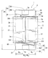
- FIG. 1 is a schematic perspective view showing a reactor of the first embodiment.
- FIG. 2 is a schematic plan view showing the reactor of the first embodiment.
- FIG. 3 is a schematic side view showing the reactor of the first embodiment.
- FIG. 4 is a schematic front view of the first composite core included in the reactor of the first embodiment as viewed from the outer end face side in the axial direction of the coil winding portion.
- FIG. 5A is a schematic front view of another example of the first composite core provided in the reactor of the second embodiment as viewed in the axial direction of the coil winding portion from the outer end face side.
- FIG. 5B is a schematic front view of still another example of the first composite core provided in the reactor of the third embodiment as seen from the outer end face side in the axial direction of the coil winding portion.
- FIG. 1 is a schematic perspective view showing a reactor of the first embodiment.
- FIG. 2 is a schematic plan view showing the reactor of the first embodiment.
- FIG. 3 is a schematic side view showing the reactor of the
- FIG. 6 is a schematic side view showing a magnetic core provided in the reactor of the fourth embodiment.
- FIG. 7: is a schematic side view which shows the magnetic core with which the reactor of Embodiment 5 is equipped.
- FIG. 8A is a schematic front view of the holding member provided in the reactor of the sixth embodiment as viewed in the axial direction of the through hole from the side where the outer core portion is arranged.
- FIG. 8B is a schematic front view showing a state in which the first composite core is arranged on the holding member shown in FIG. 8A.
- the reactor is difficult for the reactor to be magnetically saturated even when the current value used is large. However, further miniaturization is difficult. If the resin gap portion is omitted, the length of the winding portion in the reactor along the axial direction can be shortened. In this respect, the reactor is small in size, but magnetically saturated easily.
- one of the purposes of the present disclosure is to provide a compact reactor in which magnetic saturation is difficult.
- the reactor of the present disclosure is hard to undergo magnetic saturation and is small.
- a reactor according to one aspect of the present disclosure is A coil, Magnetic core, A resin mold portion that covers at least a part of the outer peripheral surface of the magnetic core;
- the coil is Two winding parts and a connecting part connecting the both winding parts,
- the magnetic core is An inner core portion arranged inside each of the winding portions, and an outer core portion arranged outside of the winding portions, At least one of the outer core portions is
- a height direction is a direction orthogonal to both the axial direction of the winding part and the arrangement direction of the winding parts, and a molded body of a composite material containing magnetic powder and a resin and a powder compact of the magnetic powder are formed.
- the connecting portion is provided on one end side in the axial direction of the both winding portions so as to project outward in the axial direction and upward in the height direction from an end portion of the inner core portion,
- the composite core is Arranged on one axial side of both winding parts, There is a portion projecting upward in the height direction with respect to a virtual surface extending the outer peripheral surface of the inner core portion,
- a molded body of the composite material is arranged on the upper side in the height direction, and includes a first composite core in which the green compact is laminated on the lower side in the height direction,
- the resin mold portion includes a first outer resin portion that covers the first composite core.
- the reactor of the present disclosure includes a composite core that includes both a molded body of a composite material and a powder compact, so that it is difficult to magnetically saturate and is small, as described below.
- the molded body of the composite material contains a relatively large amount of resin which is a non-magnetic material.
- the molded body of the composite material contains, for example, 10% by volume or more of resin. Therefore, the molded body of the composite material typically has a smaller relative magnetic permeability than the powder compacted body, and is less likely to undergo magnetic saturation. Therefore, a magnetic core including the above composite core does not include a molded body of a composite material and has a smaller relative magnetic permeability than that of a magnetic core formed of a powder compact and is less likely to undergo magnetic saturation.
- the reactor of the present disclosure has a gapless structure that typically does not include a gap plate or the above-described resin gap portion, but is hard to magnetically saturate even when the used current value is large.
- the reactor of the present disclosure can maintain a predetermined inductance even when the used current value is large.
- the magnetic core including the above composite core does not include a powder compact, and is more likely to reduce the leakage flux to the outside than the magnetic core formed of a composite material compact. Therefore, the loss due to the leakage magnetic flux is reduced. Therefore, the reactor of the present disclosure has low loss.
- the magnetic core including the composite core can reduce the volume when it has the same inductance as compared with the magnetic core formed of the composite material compact without including the powder compact.
- the outer core portion on the one end side of the winding portion, that is, the side on which the coupling portion is arranged includes the first composite core.
- the first composite core includes a portion protruding above the inner core portion in the height direction, that is, on the side where the connecting portion is arranged.
- the upper surface in the height direction of the inner core portion and the upper surface in the height direction of the outer core portion, that is, the surface on the side where the connecting portion is arranged in the outer core portion are typically formed. It's the same.
- FIG. 4 of Patent Document 1 For this flush configuration, refer to FIG. 4 of Patent Document 1, for example.
- it is surrounded by a surface of the outer core portion on the side of the coupling portion, end surfaces of both winding portions, and an imaginary surface of the outer peripheral surface of both winding portions, which is an extension of the upper surface in the height direction. Space is dead space.
- the protruding portion of the first composite core on the connecting portion side is arranged in the dead space.
- the axial length of the magnetic core can be made shorter than that of the conventional reactor described above.
- the reactor of the present disclosure can shorten the axial length.
- the axial length is the length along the axial direction of the winding portion of the reactor.
- the first composite core is provided with a molded body of the composite material on the upper side in the height direction, that is, on the connecting portion side.
- the molded body of the composite material can be manufactured into various three-dimensional shapes by injection molding or the like, and has a high degree of freedom in shape as compared with the powder compact. Therefore, the molded body of the composite material can be easily molded into a shape corresponding to the shape near the connecting portion. From this point, the above-mentioned dead space is easily utilized, and the axial length of the magnetic core is likely to be shortened.
- the reactor of the present disclosure is excellent in manufacturability as described below.
- the first composite core is a laminate of a composite material compact and a powder compact. Therefore, it is possible to independently form two molded bodies, that is, the molded body of the composite material and the compacted body.
- the powder compact has a simple shape such as a rectangular parallelepiped, the powder compact can be easily and accurately molded.
- the molded body of the composite material corresponds to the shape near the above-mentioned connecting portion, and even if the shape also corresponds to the surface of the molded body of the composite material that comes into contact with the powder compact, easily by injection molding or the like, And can be molded with high precision.
- both the molded body of the composite material and the compacted body are excellent in manufacturability. Furthermore, if the surface forming the interface between the two molded bodies is a flat surface, the two molded bodies can be easily stacked without a gap. Also from this point, the reactor of the present disclosure is excellent in manufacturability.
- the thickness of the central portion in the arrangement direction of the winding portions is thicker than the thickness of both ends in the arrangement direction of the winding portions.
- the magnetic flux easily passes through the central part of the outer core part in the arrangement direction of both winding parts, compared to both ends in the arrangement direction.
- the thickness of the portion where the magnetic flux easily passes is locally thick, magnetic saturation is difficult to occur even when the used current value is large.
- the axial length of the magnetic core can be shortened to be small in size, and the weight can be reduced.
- the connecting portion is formed by bending a part of a winding wire forming the winding portions,
- the first composite core has a recess in which the connecting portion is arranged,
- the molded body of the composite material forming the first composite core may be in the form of at least a part of the inner peripheral surface forming the recess.
- the concave portion by providing the concave portion, it is easy to increase the height of the first composite core by utilizing the dead space while avoiding the contact between the coil connecting portion and the first composite core.
- the above-described embodiment is hard to be magnetically saturated, and the axial length of the magnetic core is easily shortened, and thus the size is small.
- at least a part of the inner peripheral surface forming the concave portion is formed of a molded body of the composite material, so that the concave portion having a shape corresponding to the connecting portion can be easily molded.
- the above form is more excellent in manufacturability in that the first composite core having the concave portion can be easily formed.
- a frame-shaped holding member that holds the end faces of the winding parts and the first composite core may have a form in which a molded body of the composite material forming the first composite core is integrally molded.
- the holding member and the powder compact By assembling the holding member and the powder compact in the above-described form, it is possible to stack the composite material compact and the powder compact and to assemble the holding member to the laminate at the same time. Further, the holding member facilitates maintaining the stacked state of the above-mentioned stacked body. From these points, the above form is more excellent in manufacturability.
- the composite core is Arranged on the other end side in the axial direction of both winding parts, Including a second composite core having a portion protruding in the height direction from the virtual surface of the inner core portion,
- the resin mold portion includes a second outer resin portion that covers the second composite core,
- the molded body of the composite material that constitutes the second composite core has an overhanging portion that projects outward in the axial direction of the winding portion from the powder compact that constitutes the second composite core. It may be provided with a form.
- the content ratio of the composite material molded body in the magnetic core is large. From this point, the above-mentioned form is hard to be magnetically saturated. Moreover, in the said form, an overhang
- projection part can be utilized for a terminal block, for example. Such a form is small in size because it is easy to shorten the axial length of the reactor including the terminal block.
- the inner core portion may be in the form of a molded body of a composite material containing magnetic powder and resin.
- the inner core portion in addition to the first composite core, also includes a composite material molded body, so the content ratio of the composite material molded body in the magnetic core is higher. From this point, the above-mentioned form is hard to be magnetically saturated.
- the relative permeability of the molded body of the composite material is 5 or more and 50 or less, A form in which the relative magnetic permeability of the green compact is twice or more the relative magnetic permeability of the composite material compact is mentioned.
- the above-mentioned form has a large inductance and is easy to miniaturize as compared with the case where a magnetic core made of a composite material molded body is not included without including a powder compact. Further, in the above-mentioned embodiment, the relative magnetic permeability of the molded body of the composite material is relatively low. The form including such a molded body of a low magnetic permeability composite material is hard to be magnetically saturated. Furthermore, the above-mentioned form can reduce the leakage magnetic flux between the composite material compact and the powder compact. From this point, the above-described embodiment can reduce the loss due to the above-mentioned leakage magnetic flux.
- the relative magnetic permeability of the green compact may be 50 or more and 500 or less.
- FIG. 1 is a perspective view showing an outline of the reactor 1 of the first embodiment, and shows a state in which a connecting portion 2j for connecting the winding portions 2a and 2b of the coil 2 is arranged so as to be diagonally lower left in the drawing.
- FIG. 2 is a plan view of the reactor 1 of the first embodiment viewed from a direction orthogonal to both the axial direction of the winding portions 2a and 2b and the arrangement direction of the winding portions 2a and 2b.
- the holding member 5 is omitted for the sake of clarity, and the resin mold portion 6 is virtually shown by a chain double-dashed line.
- FIG. 1 is a perspective view showing an outline of the reactor 1 of the first embodiment, and shows a state in which a connecting portion 2j for connecting the winding portions 2a and 2b of the coil 2 is arranged so as to be diagonally lower left in the drawing.
- FIG. 2 is a plan view of the reactor 1 of the first embodiment viewed from a direction orthogonal to both the axial
- FIG. 3 is a side view of the reactor 1 of the first embodiment as viewed from the winding portion 2a side in the direction in which both winding portions 2a and 2b are arranged.
- the holding member 5 and the resin mold portion 6 are omitted so that the magnetic core 3 can be easily seen.
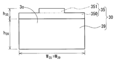
- FIG. 4 is a front view of the first composite core 30 included in the reactor 1 of the first embodiment as viewed from the outer end surface 3o side in the axial direction of the winding portions 2a and 2b.
- the lower side of the paper surface in FIGS. 1, 3, and 4 and the rear side in the vertical direction of the paper surface in FIG. 2 will be described as the installation side of the reactor 1. This installation direction is an example, and can be changed as appropriate.
- the reactor 1 of the first embodiment includes a coil 2, a magnetic core 3, and a resin mold portion 6.
- the coil 2 includes two winding parts 2a and 2b.
- the two winding parts 2a and 2b are arranged next to each other and are arranged so that their axes are parallel to each other (FIG. 2).
- the coil 2 includes a connecting portion 2j that connects the winding portions 2a and 2b.
- the magnetic core 3 is arranged inside and outside the winding portions 2a and 2b.
- the magnetic core 3 includes an inner core portion 31 arranged inside each winding portion 2a, 2b and an outer core portion 32 arranged outside each winding portion 2a, 2b. ..
- the inner core portion 31 and the outer core portion 32 form an annular closed magnetic circuit.
- Each inner core portion 31 is arranged so that its axial direction is along the axial direction of the winding portions 2a and 2b.
- Both inner core portions 31 are one end side of both winding portions 2a and 2b, the outer core portion 32 arranged on the lower side of the paper in FIG. 2, and the other end side of both winding portions 2a and 2b, the paper surface in FIG. It is sandwiched between the outer core portion 32 arranged on the upper side.
- the resin mold portion 6 covers at least a part of the outer peripheral surface of the magnetic core 3.
- Such a reactor 1 is typically used by being attached to an installation target (not shown) such as a converter case.
- At least one of the two outer core portions 32 described above includes a composite core in which different kinds of core members are laminated. Details will be described with reference to FIG. A direction orthogonal to both the axial direction of the winding portions 2a and 2b and the arrangement direction of the winding portions 2a and 2b is referred to as a height direction.
- the connecting portion 2j protrudes axially outward of the winding portions 2a, 2b and upward in the height direction of the winding portions 2a, 2b at one end side in the axial direction of the winding portions 2a, 2b than the end portion of the inner core portion 31. Is provided.
- the composite core is formed by stacking a compact 35 of a composite material containing magnetic powder and a resin and a compact 39 of magnetic powder in the height direction.
- the reactor 1 includes the following first composite core 30 as one of the composite cores.
- the resin mold portion 6 includes a first outer resin portion 60 that covers the first composite core 30 (FIGS. 1 and 2).
- the axial direction of the winding parts 2a and 2b corresponds to the left-right direction on the paper surface of FIG.
- the arranging direction of the two winding portions 2a and 2b corresponds to the direction orthogonal to the paper surface of FIG.
- the direction orthogonal to both the axial direction and the arranging direction corresponds to the vertical direction on the paper surface of FIG.
- the outer side in the axial direction corresponds to the left side of the paper in FIG.
- the upper side in the height direction corresponds to the upper side of the paper in FIG.
- One end side in the axial direction corresponds to the left side of the paper in FIG. 3, and the other end side in the axial direction described later corresponds to the right side in the paper in FIG.
- the first composite core 30 is arranged on one end side in the axial direction of the winding parts 2a and 2b. Further, the composite core 30 has a portion projecting upward in the height direction with respect to a virtual surface obtained by extending the outer peripheral surface of the inner core portion 31.
- the molded body 35 of the composite material is arranged on the upper side in the height direction, and the powder compact 39 is laminated on the lower side in the height direction.
- the composite core 30 of this example includes a total of two compacts, one compact 35 of a composite material and one compact 39.
- the composite core 30 of the present example also has a portion projecting downward in the height direction with respect to the above-mentioned virtual surface in the inner core portion 31.
- the maximum height h 32 of such a composite core 30 is higher than the height h 31 of the inner core portion 31.
- the magnetic core 3 of the present example includes, as another composite core, a second composite core 34 arranged on the other end side of the winding parts 2a and 2b.
- the second composite core 34 has a portion protruding in the height direction from the above-mentioned virtual surface of the inner core portion 31.
- the composite core 34 of the present example has locations that project to both the upper side and the lower side of the inner core portion 31 in the height direction.
- the maximum height h 32 of such a composite core 34 is higher than the height h 31 of the inner core portion 31.
- the inner core portion 31 of this example includes a molded body 37 of composite material.
- the magnetic core 3 of this example has a gapless structure having no magnetic gap.
- the magnetic gap here is a hollow body such as a gap plate such as an alumina plate, a solid body such as the resin gap portion described above, or an air gap.
- a bonding material such as an adhesive that bonds the composite material compact 35 and the powder compact 39 to each other does not form a magnetic gap.
- the magnetic core 3 including both the molded body 35 of the composite material and the powder compact 39 contributes to reducing the magnetic saturation by reducing the relative magnetic permeability to some extent.
- the first composite core 30 having a portion that protrudes above the inner core portion 31 in the height direction, that is, on the side of the connecting portion 2j utilizes the dead space generated around the connecting portion 2j in the conventional reactor.
- the axial length L 3 (FIG. 2) of the magnetic core 3 is shortened.
- Such a composite core 30 contributes to miniaturization of the magnetic core 3.
- the height direction is a direction orthogonal to both the axial direction and the arranging direction of the above-described winding portions 2a and 2b when the reactor 1 is installed.
- the length along the height direction is called height.
- the axial direction of the magnetic core 3 is a direction along the axial direction of the inner core portion 31.
- the axial direction of the inner core portion 31 is along the axial direction of the winding portions 2a and 2b, and is substantially parallel.
- the length along the axial direction is called the axial length.
- the width direction is a direction orthogonal to both the height direction and the axial direction.
- the width direction of the magnetic core 3 is along the direction in which the two winding portions 2a and 2b are arranged.
- the length along the width direction is called width.
- the coil 2 includes cylindrical winding portions 2a and 2b and a connecting portion 2j.
- one continuous winding wire 2w is spirally wound to form winding portions 2a and 2b.
- the connecting portion 2j is formed by the portion of the winding 2w that is passed between the winding portions 2a and 2b.
- the connecting portion 2j electrically connects the winding portions 2a and 2b in series and also mechanically connects the winding portions 2a and 2b.
- the connecting portion 2j of this example is formed by bending a part of the winding wire 2w that constitutes both winding portions 2a and 2b. Specifically, the connecting portion 2j is configured by winding the winding 2w toward one end of the other winding portion 2b at one end of the one winding portion 2a (FIG. 2). By this rewinding, the connecting portion 2j is locally generated from the end surfaces of the two winding portions 2a and 2b, outwardly in the axial direction of the both winding portions 2a and 2b, that is, a portion protruding downward in FIG. Such a connecting portion 2j projects outward in the axial direction from the end portion of the inner core portion 31.
- the connecting portion 2j is provided such that its upper surface in the height direction has substantially the same height as the upper surface in the height direction of the outer peripheral surfaces of the winding portions 2a, 2b. Such a connecting portion 2j projects to the upper side in the height direction than the upper surface in the height direction of the virtual surface extending the outer peripheral surface of the inner core portion 31.
- the upper surface in the height direction is the upper surface in FIG. 3, and here is the surface opposite to the installation side.
- the shape of one end of each of the winding portions 2a and 2b has an uneven shape corresponding to the shape of the connecting portion 2j described above.
- the shape on the other end side of both winding parts 2a, 2b is formed mainly by the end faces of both winding parts 2a, 2b and is a relatively flat shape. Therefore, it can be said that the shape of one end of each of the winding portions 2a and 2b is more complicated than the shape of the other end.
- the winding 2w may be a covered wire that includes a conductor wire and an insulating coating that covers the outer circumference of the conductor wire.
- a covered wire that includes a conductor wire and an insulating coating that covers the outer circumference of the conductor wire.
- the constituent material of the conductor wire copper or the like can be mentioned.
- the constituent material of the insulating coating include resins such as polyamide-imide.
- Specific examples of the covered wire include a covered rectangular wire having a rectangular cross section and a covered round wire having a circular cross section.
- An edgewise coil is mentioned as a specific example of the winding portions 2a and 2b made of a rectangular wire.
- the winding 2w in this example is a coated rectangular wire.
- the winding portions 2a and 2b of this example are square tube-shaped edgewise coils. Further, in this example, the specifications of the shape, the winding direction, and the number of turns of the winding portions 2a and 2b are the same.
- the shape and size of the winding 2w and the winding portions 2a and 2b can be changed as appropriate.
- the winding portions 2a and 2b may have a cylindrical shape or the like.
- the specifications of the winding portions 2a and 2b may be different.
- the ends of the windings 2w drawn out from the windings 2a and 2b, that is, the right ends in FIGS. 1 and 3, are used as places to which external devices such as a power source are connected.
- the magnetic core 3 of the present example has a portion arranged inside the winding portions 2a and 2b, and is mainly arranged on the member forming the inner core portion 31 and outside the winding portions 2a and 2b.
- a total of four columnar members which are mainly members constituting the outer core portion 32, are provided.
- a member mainly forming the inner core portion 31 includes a molded body 37 of a composite material.
- the members that mainly constitute the outer core portion 32 include a first composite core 30 and a second composite core 34.
- One end surface of the molded body 37 of each composite material and the inner end surface 3e of the composite core 30 are connected.
- the other end surface of the molded body 37 of each composite material and the inner end surface 3e of the composite core 34 are connected. With this connection, the above four members are formed in an annular shape.
- the magnetic core 3 of this example has a gapless structure.
- the constituent material of the member mainly forming the inner core portion 31 and the constituent material of the member mainly forming the outer core portion 32 are different.
- the constituent materials of the members forming the inner core portions 31 are the same.
- the constituent material of the first composite core 30 and the constituent material of the second composite core 34 are the same.
- the constituent material and the number of each member can be appropriately changed.
- the first composite core 30 mainly comprises an outer core portion 32 arranged on one axial side of the winding portions 2a and 2b, that is, on the connecting portion 2j side.
- the composite core 30 is configured by stacking different kinds of core members, which are a composite material compact 35 and a powder compact 39, in the height direction.
- the composite material molded body 35 is disposed on the upper side in the height direction of the composite core 30, that is, on the side of the connecting portion 2j.
- the powder compact 39 is arranged on the lower side in the height direction of the composite core 30.
- the lower side in the height direction is the side opposite to the connecting portion 2j and corresponds to the installation side here.
- the composite core 30 has a portion protruding in the height direction from the inner core portion 31. Therefore, the maximum height h 32 of the composite core 30 is higher than the height h 31 of the inner core portion 31. That is, h 31 ⁇ h 32 .
- the second composite core 34 mainly constitutes the outer core portion 32 arranged on the other end side in the axial direction of the winding portions 2a and 2b, that is, on the side opposite to the connecting portion 2j. Similar to the first composite core 30 described above, the composite core 34 of the present example includes a laminate of different kinds of core members, and has a portion protruding in the height direction from the inner core portion 31.
- first composite core 30 and the second composite core 34 have the same shape, the same size, the same composition, and the same structure.
- description will be made with reference to the first composite core 30.
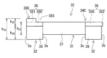
- the first composite core 30 of this example has a substantially rectangular parallelepiped shape (FIG. 1) and a rectangular shape in a plan view from the height direction (FIG. 2).
- the composite core 30 of the present example has a stepped portion with locally different heights in a plan view from the width direction (see also FIGS. 3 and 4).
- the step-shaped portion is a portion of the virtual surface obtained by extending the outer peripheral surface of the inner core portion 31 in the composite core 30 and projects upward in the height direction from the upper surface in the height direction (FIG. 3). That is, the step-shaped portion projects toward the connecting portion 2j from the virtual surface of the inner core portion 31.
- the composite core 30 of the present example also has a lower surface in the height direction of the virtual surface extending the outer peripheral surface of the inner core portion 31, that is, a portion protruding downward in the height direction from the lower surface in FIG. Have (FIG. 3). That is, the composite core 30 has a portion projecting to the opposite side of the connecting portion 2j from the virtual surface of the inner core portion 31.
- the part projecting to the side opposite to the connecting part 2j has a rectangular parallelepiped shape and a simple shape (FIG. 3).
- a portion having a relatively complicated shape such as the above-described step shape is formed by the composite material molded body 35. Further, in the composite core 30 of the present example, the portion to which the inner core portion 31 is connected and the portion which protrudes to the opposite side of the inner core portion 31 from the connecting portion 2j are configured by the powder compact 39.
- the powder compact 39 of this example has a rectangular parallelepiped shape (FIGS. 1, 3, and 4) and a simple shape. Therefore, the powder compact 39 is easily and highly accurately molded.
- the upper surface in FIGS. 3 and 4 is a surface on which the composite material compact 35 is laminated.
- this upper surface is referred to as the upper surface of the powder compact 39.
- a surface forming a part of the inner end surface 3e is a surface mainly contacting the end surface of the composite material compact 37 forming the inner core portion 31 (FIG. 3). ).
- the molded body 35 of the composite material of this example is present above the upper surface of the powder compact 39 in the height direction. However, the composite material compact 35 does not protrude from the outer peripheral surface of the powder compact 39 in both the width direction and the axial direction of the magnetic core 3.
- the maximum width W 35 and the maximum axial length of the composite material compact 35 are equal to the width W 39 and the maximum axial length of the powder compact 39 (FIGS. 2 to 4).
- the maximum axial length corresponds to the vertical length in FIG. 2 and the horizontal length in FIG.
- the molded body 35 of the composite material of this example has a shape corresponding to the upper surface of the powder compact 39 and a shape corresponding to the shape near the connecting portion 2j.
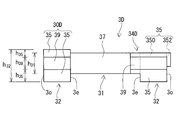
- the molded body 35 of the composite material of this example has a base portion 350 laminated on the upper surface of the powder compact 39 and a protrusion 351 locally higher than the base portion 350 (FIGS. 2 to 4). 4).
- the composite core 30 of this example has a recess 355 in which the connecting portion 2j is arranged (FIGS. 2 and 3).
- the molded body 35 of the composite material constitutes a part of the inner peripheral surface of the recess 355.
- the second composite core 34 has the concave portion 355, the connecting portion 2j is not arranged in the concave portion 355 (FIG. 2).
- the base 350 of the present example is a relatively flat rectangular parallelepiped having a rectangular surface having the same shape and the same size as the upper surface of the powder compact 39, and has a polygonal column shape with one corner cut off. ( Figure 2). Reference may also be made to the base 350 of the second composite core 34.
- One surface of the base 350, the lower surface in FIGS. 3 and 4, is a surface that contacts the upper surface of the powder compact 39.
- this lower surface is referred to as the lower surface of the base 350 or the lower surface of the molded body 35 of the composite material.
- the lower surface of the base portion 350, together with the upper surface of the powder compact 39, constitutes a boundary between the composite material compact 35 and the powder compact 39.
- a protrusion 351 is provided on the other surface facing the lower surface of the base portion 350, that is, the upper surface in FIGS. 3 and 4.
- this upper surface is referred to as the upper surface of the base 350.
- the base 350 of this example has an inclined surface 35f that intersects the width direction of the base 350 and the axial direction of the magnetic core 3 as one surface connecting the lower surface of the base 350 and the upper surface of the base 350 (FIG. 2).
- the inclined surface 35f is a side edge in the width direction of the base portion 350, and is provided so as to extend from the intermediate position in the axial direction to the intermediate position in the width direction on the inner end surface 3e.
- a space in the shape of a right triangle formed by the inclined surface 35f and a part of the upper surface of the powder compact 39 is a recess 355.
- the inclination angle ⁇ of the inclined surface 35f with respect to the inner end surface 3e generally corresponds to the intersecting angle of the winding portions 2a and 2b in the rewinding portion of the connecting portion 2j with respect to the end surface.
- the maximum distance of the inclined surface 35f from the inner end surface 3e substantially corresponds to the protruding length from the end surface of the winding portions 2a and 2b in the rewinding portion. Therefore, the recess 355 can satisfactorily accommodate the connecting portion 2j.
- the recess 355 is composed of the composite material compact 35 and the powder compact 39, the composite compact 35 is likely to have a simple shape to some extent. Therefore, the molded body 35 of the composite material is excellent in manufacturability.
- the recess 355 may be formed by the molded body 35 of the composite material. For the configuration, refer to Embodiment 4 described later.
- the projecting portion 351 of the present example has a rectangular parallelepiped shape, is a central portion in the width direction of the base portion 350 (FIGS. 2 and 4), and is arranged near the outer end surface 3o (FIGS. 2 and 3).
- the thickness of the central portion in the width direction is thicker than the thickness of both end portions in the width direction.
- the thickness is the length along the height direction and corresponds to the height.
- the magnetic flux easily passes as compared with the end portions in the width direction.
- the magnetic core 3 is less likely to be magnetically saturated by providing the protrusion 351 at a location where the magnetic flux easily passes.
- the protruding portion 351 near the outer end surface 3o, the leakage magnetic flux from the outer core portion 32 to the outside can be easily reduced. From this point, the magnetic core 3 tends to have a low loss. Further, by providing the locally thick portion by the protruding portion 351, the axial length L 3 of the magnetic core 3 becomes shorter as compared with the case where the thickness of the composite material molded body 35 is the same throughout. The weight can be reduced.
- both the lower surface of the composite material compact 35 and the upper surface of the powder compact 39 are rectangular flat surfaces and are arranged so as to be orthogonal to the height direction. If both surfaces are flat, the molded body 35 of the composite material and the powder molded body 39 are easily laminated without a gap in the manufacturing process. In addition, if the above-mentioned two surfaces are planes arranged so as to be orthogonal to the height direction, the composite material compact 35 and the powder compact 39 are likely to be stably laminated in the height direction.
- the interface formed by the lower surface of the composite material compact 35 and the upper surface of the powder compact 39 is orthogonal to the height direction as described above, the interface is arranged substantially parallel to the magnetic flux direction.
- the magnetic flux direction is along the axial direction of the winding portions 2a and 2b, and corresponds to the left-right direction on the paper surface in FIG.
- the interface is located at substantially the same height as the upper surface of the outer peripheral surface of the inner core portion 31 in the height direction. If the interface is substantially parallel to the magnetic flux direction, even if there is a minute gap between the compact 35 of the composite material and the powder compact 39, for example, a gap of 0.1 mm or less, the magnetic path is The impact is considered to be practically negligible.
- the interface Since the interface is located at a position other than the end face of the inner core portion 31, here, at a position other than the end face of the molded body 37 of the composite material, it is considered that the influence on the magnetic path is small. Therefore, the minute gap is allowed.
- the interface may be provided so as to intersect with the magnetic flux direction. However, in consideration of the influence on the magnetic path, workability during lamination, and the like, it is preferable that the interface is substantially parallel to the magnetic flux direction as in this example.
- the position of the interface may be arranged at the position of the end surface of the inner core portion 31. For this configuration, refer to Embodiments 4 and 5 described later.
- Size of molded product The size of the member forming the outer core portion 32 and the size of the member forming the inner core portion 31, which will be described later, are adjusted according to the constituent materials and the like so that the reactor 1 satisfies predetermined magnetic characteristics.
- the size of the powder compact 39 that constitutes the first composite core 30 and the second composite core 34 of this example is as follows.
- the width W 39 of the powder compact 39 is larger than the total value of the widths W 31 of the two inner core portions 31 arranged adjacent to each other (FIG. 2). That is, 2 ⁇ W 31 ⁇ W 39 .
- the height h 39 of the green compact 39 is greater than the height of the inner core portion 31, here the height h 31 of the composite compact 37 (FIG. 3). That is, h 31 ⁇ h 39 .
- the height h 39 of the powder compact 39 is the sum of the height h 31 of the inner core portion 31 and the length protruding from the inner core portion 31 downward in the height direction. In this example, the protruding length of the green compact 39 satisfies the following.
- the above-mentioned protrusion length means a lower surface in the height direction of the powder compact 39 from the lower surface in the virtual surface extending the outer peripheral surface of the inner core portion 31.
- the lower surface in the height direction is the lower surface in FIG. 3, and corresponds to the installation surface here.
- the lower surface in the height direction of the powder compact 39 is flush with the lower surface in the height direction of the outer peripheral surfaces of the winding portions 2a and 2b. It is about the size.
- the area of the surface forming the inner end surface 3e of the powder compact 39 is larger than the total area of the end surfaces of the two inner core portions 31.
- the size of the molded body 35 of the composite material forming the first composite core 30 and the second composite core 34 of this example is as follows.
- the region on the outer end face 3o side has the maximum width, and the width decreases continuously from the intermediate position in the axial direction of the magnetic core 3 toward the inner end face 3e according to the inclined surface 35f (FIG. 2). ..
- the maximum width of the base portion 350 is equal to the maximum width W 35 of the molded body 35 of the composite material. Therefore, the maximum width of the base 350 is equal to the width W 39 of the green compact 39 (FIG. 4).
- the axial length of the base portion 350 has the maximum axial length in the region on the one end side in the width direction, and continuously decreases from the intermediate position in the width direction toward the other end side in the width direction according to the inclined surface 35f. ( Figure 2).
- the axial length is maximum in the region on the left end side in the width direction, and becomes shorter from the intermediate position in the width direction toward the right end side.
- the maximum axial length of the base 350 is equal to the maximum axial length of the green compact 39 (FIGS. 2 and 3).
- the height of the base part 350 is from the upper surface of the powder compact 39 to the vicinity of the lower end of the connecting part 2j in the height direction (FIG. 3).
- the width of the protrusion 351 is smaller than the maximum width of the base 350 (FIGS. 2 and 4). For example, the width of the protrusion 351 is 20% or more and 60% or less of the maximum width of the base 350.
- the axial length of the protrusion 351 is shorter than the maximum axial length of the base 350.
- the inner edge of the protrusion 351 does not reach the inner end surface 3e or the inclined surface 35f (FIG. 2).
- the axial length of the protrusion 351 may be 40% or more and 75% or less of the maximum axial length of the base 350.
- the height of the protruding portion 351 is from the vicinity of the lower end to the vicinity of the upper end of the connecting portion 2j in the height direction (FIG. 3).
- the total value of the height of the base portion 350 and the height of the protruding portion 351, that is, the height h 35 of the molded body 35 of the composite material is determined by winding the inner core portion 31 from the surface in the height direction higher than the above-described virtual surface. Of the outer peripheral surfaces of the turning portions 2a and 2b, it is only about the upper surface in the height direction (FIG. 3). For example, the height h 35 of the molded body 35 of the composite material is 30% or more and 60% or less of the height h 31 of the inner core portion 31.
- the protrusion 351 can easily secure a large volume while avoiding interference with the connecting portion 2j. Since the volume of the protrusion 351 is large, the magnetic core 3 is less likely to be magnetically saturated. In particular, if the width of the protrusion 351 is smaller than the width of the base 350 and the above range is satisfied, the height of the protrusion 351 and thus the height h 35 of the molded body 35 of the composite material can be made higher. Therefore, in the composite cores 30 and 34, a large volume of the composite material molded body 35 is easily secured in the central portion in the width direction where the magnetic flux easily passes as described above. As a result, the magnetic core 3 is less likely to be magnetically saturated.
- the size of the above-described powder compact 39 and the size of the composite compact 35 can be appropriately changed within a range in which the reactor 1 satisfies predetermined magnetic characteristics.
- the maximum width W 35 of the composite material compact 35 may be smaller than the width W 39 of the powder compact 39.
- the maximum axial length of the composite material compact 35 may be smaller than the maximum axial length of the powder compact 39.
- the maximum axial length of the composite material compact 35 may be somewhat larger than the maximum axial length of the powder compact 39.
- the content ratio of the molded body 35 of the composite material to the total volume of the first composite core 30 can be appropriately selected within the range where the reactor 1 satisfies the predetermined magnetic characteristics.
- the content ratio is, for example, 5% by volume or more and 70% by volume or less.
- the balance is the volume ratio of the powder compact 39. Although it depends on the relative magnetic permeability of the composite material molded body 35 and the relative magnetic permeability of the powder compact 39, the volume ratio of the composite material molded body 35 satisfies the above range, so that the gapless magnetic core 3 is obtained. However, magnetic saturation is difficult.
- the member forming the outer core portion 32 may be a columnar body having a dome shape or a trapezoidal shape in plan view from the height direction as shown in Patent Document 1.
- the molded body 37 of each composite material is mainly arranged in the winding portions 2a and 2b.
- the end of the molded body 37 of each composite material is arranged outside the winding portions 2a and 2b together with the first composite core 30 and the second composite core 34 to form the outer core portion 32 (FIG. 3).
- the molded body 37 of each composite material does not have a magnetic gap such as a gap plate, and is an integrated body made of the composite material.
- the molded bodies 37 of each composite material have the same shape, the same size, and the same composition.
- the molded body 37 of each composite material has a rectangular parallelepiped shape.
- the outer peripheral shape of the molded body 37 of each composite material is substantially similar to the inner peripheral shape of the winding portions 2a and 2b.
- the axial length of the molded body 37 of each composite material is slightly longer than the axial length of each winding portion 2a, 2b. Therefore, when the molded body 37 of each composite material and the coil 2 are assembled, the end portion of the molded body 37 of each composite material projects from the winding portions 2a and 2b. Therefore, the end surface of the molded body 37 of the composite material, the inner end surface 3e of the first composite core 30, and the inner end surface 3e of the second composite core 34 easily contact each other.
- the shape, size, structure, etc. of the member forming the inner core portion 31, here mainly the composite material molded body 37, can be appropriately changed.
- the shape of the member forming the inner core portion 31 may be cylindrical, polygonal, or the like.
- at least a part of the corners of the member forming the inner core portion 31 may be chamfered or chamfered. The chamfered corners are less likely to be chipped, and the member forming the inner core portion 31 has excellent mechanical strength.
- the member forming one inner core portion 31 may be formed of a plurality of core pieces. However, if the number of members forming one inner core portion 31 is one as in this example, the number of assembled parts is small and the reactor 1 is excellent in manufacturability.
- the composite material molded bodies 35 and 37 include magnetic powder and resin.
- the magnetic powder is dispersed in the resin.
- the composite material molded bodies 35 and 37 can be manufactured by an appropriate molding method such as injection molding or cast molding. Typically, a raw material containing a magnetic powder and a resin is prepared, and the raw material in a fluid state is filled in a molding die and then solidified.
- the magnetic powder powder made of a soft magnetic material, powder having a coating layer made of an insulating material or the like on the surface of powder particles, and the like can be used.
- soft magnetic materials include metals such as iron and iron alloys and non-metals such as ferrite.
- iron alloys include Fe—Si alloys and Fe—Ni alloys.
- the content of the magnetic powder in the composite material is, for example, 30% by volume or more and 80% by volume or less.
- the content of the resin in the composite material is, for example, 10% by volume or more and 70% by volume or less.
- the higher the content of the magnetic powder and the lower the content of the resin the more easily the saturation magnetic flux density and the relative magnetic permeability are increased, and the heat dissipation is enhanced.
- the content of the magnetic powder may be 50% by volume or more, further 55% by volume or more, and 60% by volume or more when the saturation magnetic flux density, the relative magnetic permeability, and the heat dissipation are desired to be improved.
- the composite material has excellent fluidity.
- the content of the magnetic powder may be 75% by volume or less, further 70% by volume or less.
- the resin content may be more than 30% by volume.
- the saturation magnetic flux density and the relative magnetic permeability can be easily changed not only by the content of the magnetic powder and the content of the resin as described above but also by the composition of the magnetic powder. ..
- the composition of the magnetic powder, the content of the magnetic powder, the content of the resin, etc. may be adjusted so that the reactor 1 has a predetermined magnetic characteristic, for example, a predetermined inductance.
- the resin in the composite material in the composite material molded bodies 35, 37 may be a thermosetting resin, a thermoplastic resin, a room temperature curable resin, a low temperature curable resin, or the like.
- thermosetting resins include unsaturated polyester resins, epoxy resins, urethane resins, and silicone resins.
- thermoplastic resins include polyphenylene sulfide (PPS) resin, polytetrafluoroethylene (PTFE) resin, liquid crystal polymer (LCP), polyamide (PA) resin such as nylon 6 and nylon 66, polybutylene terephthalate (PBT) resin, acrylonitrile. -Butadiene-styrene (ABS) resin etc. are mentioned.
- PPS polyphenylene sulfide
- PTFE polytetrafluoroethylene
- LCP liquid crystal polymer
- PA polyamide
- PCBT polybutylene terephthalate
- ABS butadiene-styrene
- the composite material molded bodies 35, 37 may contain powder made of a non-magnetic material in addition to the magnetic powder and the resin.
- non-magnetic materials include ceramics such as alumina and silica, and various metals.
- the molded articles 35, 37 of the composite material contain the powder made of the non-magnetic material to enhance the heat dissipation. Further, a powder made of a non-metal and non-magnetic material such as ceramics is preferable because it has excellent electric insulation.
- the content of the powder made of a non-magnetic material is, for example, 0.2% by mass or more and 20% by mass or less. The content may be 0.3% by mass or more and 15% by mass or less, and 0.5% by mass or more and 10% by mass or less.
- the composite materials molded bodies 35 and 37 may have the same composition or different compositions. If the molded bodies 35 and 37 of the composite material have the same composition, the magnetic characteristics of the magnetic core 3 can be easily adjusted. Further, in this case, the manufacturing conditions can be easily adjusted, and the molded products 35 and 37 of the composite material are excellent in manufacturability.
- the green compact 39 is an aggregate of magnetic powder.
- the powder compact 39 is typically formed by compression-molding a mixed powder containing the above-mentioned magnetic powder and binder into a predetermined shape and then heat-treating the mixture.
- a resin or the like can be used as the binder.
- the content of the binder is about 30% by volume or less. When heat-treated, the binder disappears or becomes a heat-modified product. Therefore, the powder compact 39 is easier to increase the content ratio of the magnetic powder than the composite compacts 35 and 37.
- the content ratio of the magnetic powder in the green compact 39 is, for example, more than 80% by volume, and further 85% by volume or more. Since the content ratio of the magnetic powder is high, the powder compact 39 tends to have higher saturation magnetic flux density and relative magnetic permeability than the compacts 35 and 37 of the resin-containing composite material.
- the relative magnetic permeability of the composite material molded bodies 35, 37 is, for example, 5 or more and 50 or less.
- the relative magnetic permeability of the molded articles 35, 37 of the composite material may be lower than 10 or more and 45 or less, further 40 or less, 35 or less, 30 or less.
- the reactor 1 including the magnetic core 3 including the compacts 35 and 37 of the composite material having such low magnetic permeability is hard to be magnetically saturated.
- the relative magnetic permeability of the green compact 39 is preferably larger than that of the composite molded bodies 35, 37.
- One of the reasons for this is that it is possible to reduce the leakage flux between the composite material compacts 35 and 37 and the powder compact 39. As a result, the loss due to the leakage magnetic flux is reduced, and the reactor 1 has low loss.
- Another reason is that the reactor 1 has a large inductance as compared with the case where the relative permeability of the green compact 39 is equal to that of the composite compacts 35 and 37, for example, 5 to 50. At the same time, it is easy to be small.
- the relative magnetic permeability of the powder compact 39 is at least twice the relative magnetic permeability of the composite compacts 35, 37, then the composite compacts 35, 37 and the powder compact 39 will be separated from each other.
- the leakage flux of is reduced more reliably.
- the relative magnetic permeability of the powder compact 39 is 2.5 times or more, more than 3 times, 5 times or more, 10 times or more that of the composite materials 35, 37. But it's okay.
- the relative magnetic permeability of the green compact 39 is, for example, 50 or more and 500 or less.
- the relative magnetic permeability of the green compact 39 may be 80 or more, 100 or more, 150 or more, 180 or more.
- Such a powder compact 39 having a high magnetic permeability can easily increase the difference from the relative magnetic permeability of the molded products 35, 37 of the composite material.
- the relative magnetic permeability of the composite material molded bodies 35 and 37 is 50 and the relative magnetic permeability of the green compact 39 is 100 or more, it is twice the relative magnetic permeability of the composite material molded bodies 35 and 37. That is all. Due to the large difference in the relative magnetic permeability, the leakage magnetic flux between the composite material compacts 35, 37 and the powder compact 39 is more easily reduced as described above, and the reactor 1 has a lower loss. ..
- the relative magnetic permeability here is calculated as follows.
- a ring-shaped sample having the same composition as the composite material compacts 35, 37 and the powder compact 39 is prepared.
- the ring-shaped sample has an outer diameter of 34 mm, an inner diameter of 20 mm, and a thickness of 5 mm.
- the maximum value of B / H of the obtained BH initial magnetization curve is obtained. This maximum value is the relative magnetic permeability.
- the magnetization curve here is a so-called DC magnetization curve.
- the relative magnetic permeability of the composite material molded bodies 35, 37 of this example is 5 or more and 50 or less.
- the relative magnetic permeability of the green compact 39 is 50 or more and 500 or less, and is twice or more the relative magnetic permeability of the composite material compacts 35 and 37.
- the relative permeability of the molded body 35 of the composite material provided in each composite core 30, 34 is substantially the same.
- the relative magnetic permeability of the powder compact 39 provided in each of the composite cores 30 and 34 is equal.
- the molded products 35 and 37 of the composite material of the present example have the same composition, the relative permeability of the molded products 35 and 37 of the composite material is equal. Since the composition of the composite material compact 35, the composition of the powder compact 39, and the composition of the composite compacts 35, 37 included in each of the composite cores 30, 34 are different, even if their relative magnetic permeability is different. Good.
- the reactor 1 may include a holding member 5 interposed between the coil 2 and the magnetic core 3.
- the holding member 5 is typically made of an electric insulating material and contributes to the improvement of the electric insulating property between the coil 2 and the magnetic core 3.
- the holding member 5 holds the members forming the winding portions 2a and 2b and the inner core portion 31 and the member forming the outer core portion 32, and is used for positioning the members with respect to the winding portions 2a and 2b.
- the holding member 5 typically holds the members forming the inner core portion 31 so that a predetermined gap is provided between the winding portions 2a and 2b.
- the gap can be used as a flow path for the resin in a fluid state in the process of manufacturing the resin mold portion 6.
- Such a holding member 5 also contributes to the securing of the flow path.
- the reactor 1 of this example includes a holding member 5 that holds one end surface of each of the winding portions 2a and 2b and the first composite core 30, and the other end surface of each of the winding portions 2a and 2b and the second composite.
- maintains the core 34 is provided (FIG. 1).
- the basic structure of each holding member 5 is the same.
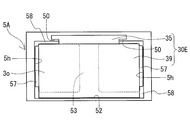
- the holding member 5 of this example is a rectangular frame-shaped member that is arranged at the end of the molded body 37 of the composite material, the inner end surface 3e of the composite core 30 or 34, and the vicinity thereof. The holding member 5 will be briefly described with reference to FIG. 8A described later.
- the holding member 5 may include the following through hole 5h, a support piece (not shown), a coil side groove (not shown), and a core side groove 52.
- the side of the holding member 5 on which the composite core 30 or 34 is arranged is referred to as the core side.
- the side of the holding member 5 on which the winding portions 2a and 2b are arranged is called the coil side.
- the through hole 5h penetrates from the core side of the holding member 5 to the coil side of the holding member 5.
- a member constituting the inner core portion 31, here, an end portion of the molded body 37 of the composite material is inserted into the through hole 5h.
- the support piece projects from a part of the inner peripheral surface forming the through hole 5h, for example, a corner toward the coil side.
- the support piece supports a part of the outer peripheral surface of the molded body 37 of the composite material, for example, a corner portion.
- This gap is used for the flow path of the resin in the fluid state as described above, and the inner resin portion, which will be described later, which is a part of the resin mold portion 6, is formed. Illustration of the inner resin portion is omitted.
- the groove portion on the coil side is provided on the coil side of the holding member 5.
- the end faces of the winding portions 2a and 2b and the vicinity thereof are fitted into the groove portion on the coil side.
- the groove portion 52 on the core side is provided on the core side of the holding member 5.
- a through hole 5h is provided in the bottom portion 53 of the groove portion 52.
- the inner end surface 3e of the composite core 30 or 34 and its vicinity are fitted into the groove 52. A part of the inner end surface 3e contacts the B-shaped bottom portion 53.
- the holding member 5 arranged on the side of the connecting portion 2j is provided with a recess 55 that accommodates the connecting portion 2j (FIG. 1).
- the recess 55 is a right-angled triangular space having a size similar to that of the recess 355 of the first composite core 30 and capable of accommodating the connecting portion 2j.
- the inclined surface 35f of the composite core 30 is arranged along a wall surface (not shown) forming the recess 55.
- the holding member 5 can have a known structure.
- the holding member 5 may include a member arranged between the winding portions 2a and 2b and the member forming the inner core portion 31 independently of the frame-shaped member described above.
- the inner intervening portion 51 of Patent Document 1 refers to the inner intervening portion 51 of Patent Document 1.
- the holding member 5 may be made of an electrically insulating material such as resin.
- resin it is preferable to refer to the section of the above-mentioned composite material molded body.
- a thermoplastic resin, a thermosetting resin, or the like can be given.
- the holding member 5 can be manufactured by a known molding method such as injection molding.
- the resin mold portion 6 covers at least a part of the magnetic core 3 to protect the magnetic core 3 from the external environment, mechanically protects the magnetic core 3 from the surrounding components of the coil 2 and the reactor 1. It has the function of increasing the electrical insulation between the two.
- the resin mold portion 6 covers the magnetic core 3 as shown in FIG. 1 and exposes the outer circumferences of the winding portions 2a and 2b without covering them, the reactor 1 has excellent heat dissipation. This is because the winding portions 2a and 2b can directly contact a cooling medium such as a liquid refrigerant.
- the resin mold portion 6 includes a first outer resin portion 60 that covers the first composite core 30.
- the resin mold portion 6 of this example includes a second outer resin portion 64 that covers the second composite core 34.
- the resin mold portion 6 of the present example includes an inner core portion 31, here an inner resin portion that covers at least a part of the composite material molded body 37.
- the resin mold portion 6 of this example includes an inner resin portion existing inside the winding portions 2a and 2b and an outer resin portion 60 existing outside the winding portions 2a and 2b and covering the outer core portion 32.
- 64 is a continuous integrally molded product.
- the composite cores 30 and 34 including the laminate of the molded body 35 of the composite material and the powder compact 39 are covered with the outer resin portions 60 and 64, so that the above-described laminate is integrated. If the inner resin portion and the outer resin portions 60 and 64 are integrally molded, the members forming the magnetic core 3 are held integrally. Therefore, the resin mold portion 6 enhances the rigidity of the magnetic core 3 as an integral body, and the reactor 1 has excellent strength.
- the holding member 5 includes a member arranged between the wound portions 2a and 2b and the member forming the inner core portion 31, the resin mold portion 6 does not include the inner resin portion. Alternatively, substantially only the outer resin portions 60 and 64 may be provided.
- the coating range, thickness, etc. of the inner resin portion and the outer resin portions 60, 64 can be appropriately selected.
- the outer resin portions 60 and 64 of this example expose the upper surface of the protrusion 351 in the height direction (FIG. 1), but may cover the upper surface.
- the resin mold portion 6 may cover the entire outer peripheral surface of the magnetic core 3.
- the outer resin portions 60, 64 include a portion that covers the interface between the molded body 35 of the composite material and the powder compact 39, a part of the composite core 30, 34, for example, on the installation side. The surface may be exposed without being covered.
- the resin mold portion 6 may have a substantially uniform thickness or may have a locally different thickness.
- thermoplastic resin examples include PPS resin, PTFE resin, LCP, PA resin, and PBT resin.
- the above-mentioned constituent materials may contain powder having excellent thermal conductivity and powder made of the above-mentioned non-magnetic material.
- the resin mold portion 6 containing the powder has excellent heat dissipation.
- the constituent resin of the resin mold portion 6 and the constituent resin of the holding member 5 are the same resin, the bondability between them is excellent. Further, since the thermal expansion coefficients of the both are the same, peeling and cracking of the resin mold portion 6 due to thermal stress are suppressed. Injection molding or the like can be used to mold the resin mold portion 6.
- the reactor 1 of Embodiment 1 can be manufactured, for example, as follows. A first composite core 30, a second composite core 34, and a composite material molded body 37 are prepared. The coil 2, the magnetic core 3, and the holding member 5 are assembled as needed. The manufactured assembly is housed in a molding die of the resin mold portion 6, and at least the composite cores 30 and 34 are covered with the resin in a fluid state. Illustration of the molding die is omitted.
- the first composite core 30 and the second composite core 34 may be prepared by stacking a composite material compact 35 and a powder compact 39 respectively.
- the composite material molded bodies 35 provided in the composite cores 30 and 34 have the same shape, the same size, and the same composition, the composite material molded body shares one molding die. 35 can be manufactured.
- the molded body 35 of the composite material and the powder compact 39 are fixed with a bonding material such as an adhesive, the composite cores 30 and 34 have excellent strength. Further, by fixing with the bonding material, it is easy to prevent the displacement of the molded body when the resin mold portion 6 is manufactured.
- a one-way filling method in which a resin in a fluid state is introduced from the outer end surface 3o of the one outer core portion 32 toward the other outer core portion 32 can be used.
- a bidirectional filling method may be used in which the resin in a fluid state is introduced from the outer end surface 3o of each outer core portion 32 toward the inside of the winding portions 2a and 2b.
- the reactor 1 of the first embodiment can be used as a component of a circuit that performs a voltage boosting operation or a voltage dropping operation, for example, a component of various converters or power conversion devices.
- the converter include an on-vehicle converter mounted on a vehicle such as a hybrid vehicle, a plug-in hybrid vehicle, an electric vehicle, a fuel cell vehicle, typically a DC-DC converter, an air conditioner converter, and the like.
- the reactor 1 of the first embodiment includes a first composite core 30 including a composite material compact 35 and a powder compact 39.
- the magnetic core 3 including the composite core 30 tends to have a smaller relative magnetic permeability than a magnetic core made of a green compact and not including a composite material compact. Even if the reactor 1 of the first embodiment including the magnetic core 3 as described above does not include a magnetic gap such as a gap plate, magnetic saturation is difficult when the used current value is large. Further, the reactor 1 can reduce the decrease in inductance even when the used current value is large.
- the magnetic core 3 includes a composite material compact 35 and a powder compact 39. Therefore, the magnetic core 3 is more likely to reduce the leakage magnetic flux to the outside than the magnetic core made of a composite material compact and not including the powder compact. Such a reactor 1 has low loss.
- the reactor 1 of the first embodiment includes the first composite core 30, so that the reactor 1 does not include a powder compact, is made of a composite material, and has a magnetic core having the same inductance. , The volume can be reduced.
- the composite core 30 is arranged on one end side of the winding portions 2a and 2b, that is, on the connecting portion 2j side.
- the composite core 30 has a portion arranged so as to fill the above-mentioned dead space formed on one end side of the winding portions 2a and 2b in the conventional reactor, that is, on the coupling portion 2j side.
- at least a part of the portion arranged near the connecting portion 2j is formed of the composite material molded body 35.
- the composite core 30 can be easily formed into a shape corresponding to the shape near the connecting portion 2j, and the dead space can be effectively utilized.
- the maximum height h 32 of the outer core portion 32 is increased, and the axial length L 3 of the magnetic core 3 can be made shorter than that of the conventional reactor. Because of the gapless structure, the axial length L 3 of the magnetic core 3 tends to be short. From this point, the reactor 1 is small.
- the reactor 1 of the first embodiment is excellent in manufacturability because it is easy to manufacture the first composite core 30.
- the reason for this is that the composite core 30 can form the composite material compact 35 and the powder compact 39 independently, and is excellent in manufacturability of each compact.
- the reactor 1 is excellent in manufacturability because the laminated products can be integrated by a simple process of laminating both the molded bodies and then covering them with the resin mold portion 6.
- the reactor 1 of this example has the following effects. (1) From the following points, the reactor 1 is less likely to undergo magnetic saturation.
- the molded body 35 of the composite material provided in the first composite core 30 has a locally thick central portion in the width direction. Therefore, a large volume of the portion of the outer core portion 32 where the magnetic flux easily passes is secured.
- a member that includes the second composite core 34 and that constitutes both outer core portions 32 includes a molded body 35 of a composite material.
- the member forming the inner core portion 31 includes a molded body 37 of composite material.
- the interface between the composite material compact 35 and the powder compact 39 is arranged parallel to the magnetic flux direction. Therefore, the influence of the interface on the magnetic path can be substantially ignored, and the predetermined magnetic characteristics are maintained.
- the reactor 1 is smaller.
- the first composite core 30 has a recess 355. Therefore, the composite core 30 can easily increase the height h 35 in a range that does not project from the upper surface in the height direction of the outer peripheral surfaces of the winding portions 2a and 2b while avoiding contact with the connecting portion 2j. .. Consequently, the maximum height h 32 of the composite core 30 can be increased. As a result, it is possible to shorten the axial length L 3 of the magnetic core 3.
- the entire region to which the end surface of the molded body 37 of the composite material forming the inner core portion 31 is mainly connected is formed by the powder compact 39.
- Such a composite core 30 includes a large amount of the powder compact 39 having a higher relative magnetic permeability than the composite material compact 35. Therefore, the axial length of the composite core 30 can be made shorter than in the case where a part of the connection region with the inner core portion 31 is formed of the composite material molded body 35.
- the reactor 1 is more excellent in manufacturability.
- the green compact 39 has a simple shape and can be easily and accurately molded.
- the concave portion 355 is formed by both the composite material compact 35 and the powder compact 39. Therefore, the molded body 35 of the composite material also has a relatively simple shape and can be molded easily and accurately.
- the lower surface of the composite material compact 35 and the upper surface of the powder compact 39 are flat surfaces that are arranged orthogonally to the height direction. Therefore, both molded bodies are easily laminated without a gap.
- the first composite core 30 and the second composite core 34 have the same shape and the same size, and can be manufactured with the same raw material and the same manufacturing conditions.
- the members forming the inner core portion 31, which are arranged inside the winding portions 2a and 2b, here, the molded body 37 of the composite material, can be manufactured under the same raw material and under the same manufacturing conditions.
- the number of members that are arranged inside one winding portion 2a or 2b and that configure the inner core portion 31 is one, and the number of parts to be assembled to the magnetic core 3 and thus the reactor 1 is small.
- the reactor 1 has a lower loss. Since the magnetic core 3 includes the molded body 37 of the composite material, iron loss such as eddy current loss is reduced as compared with the magnetic core formed of the powder compact without the molded body of the composite material. By providing the protrusion 351 of the composite material molded body 35 near the outer end surface 3o, leakage flux to the outside is reduced. From this point as well, the loss due to the leakage magnetic flux is reduced.
- the shape and size of the composite core described in the first embodiment, the number of stacked molded bodies, and the like can be changed. It is possible to change the laminated state in the manufacturing process. Further, the shape and the like of the composite core forming each outer core portion 32 can be changed.
- the differences from the first embodiment will be described in detail, and the detailed description of the configurations, effects, and the like overlapping with the first embodiment will be omitted.
- Embodiment 2 The reactor of Embodiment 2 will be described with reference to FIG. 5A.
- the first composite core 30A will be described in detail.
- 5A and FIG. 5B described later show only the first composite cores 30A and 30B, and the other components of the reactor are omitted.
- 5A and 5B are, similarly to FIG. 4, a front view of the first composite cores 30A and 30B as viewed from the outer end face 3o side.
- FIG. 5A exemplifies a state in which two opposing corner portions are chamfered in the relatively flat rectangular parallelepiped base portion 350, but R chamfering may be performed. In this respect, the same applies to Embodiment 3 described later.
- the molded body 35 of the composite material can easily be molded into such a chamfered shape.
- the volume of the corner portion removed by the above chamfering is added to the protrusion 351. Therefore, the height h 35 of the composite core 30A of FIG. 5A is higher than the height h 35 of the first composite core 30 of FIG.
- the magnetic flux is more likely to pass than in the end portion in the width direction.
- the volume of the protrusion 351 located at the center portion in the width direction is larger than that of the composite core 30 of FIG. Therefore, the magnetic core including the composite core 30A is less likely to be magnetically saturated.
- the composite core 30A with the corners removed has excellent strength.
- the corners may be chamfered or the height h 35 may be higher than that of the second composite core as described above.
- the composite material molded body 35 does not have the protrusion 351. That is, the protrusion 351 may be omitted.
- the composite core 30B has a shape such that two opposite corner portions are chamfered in a relatively flat rectangular parallelepiped.
- the first composite core 30B shown in FIG. 5B is a multi-layer structure including a plurality of composite material compacts 35.
- the composite core 30B of this example has a three-layer structure including two compacts 35 of a composite material sandwiching one compacted compact 39 from above and below.
- the powder compact 39 provided in the first composite core 30B has a rectangular parallelepiped shape. However, the height h 39 of the green compact 39 is smaller than the height h 39 of the green compact 39 included in the first composite core 30 of FIG. 4, and the height h 31 ( (See FIG. 3).
- the molded body 35 of each composite material provided in the first composite core 30B has a height higher than that of a portion protruding in the height direction from the powder compact 39, that is, an imaginary surface obtained by extending the outer peripheral surface of the inner core portion 31. A part protruding in the direction is formed.
- the molded body 35 of each composite material has a shape such that two opposite corners of a relatively flat rectangular parallelepiped are chamfered.
- the molded bodies 35 of both composite materials are arranged so that the composite core 30B has a shape that is substantially line-symmetrical about the bisector in the height direction.
- the composite core may have an asymmetric shape about the bisector in the height direction.
- the first composite core 30B has a larger content ratio of the molded body 35 of the composite material than the composite core 30 shown in FIG. 4, it is possible to construct a magnetic core that is less likely to undergo magnetic saturation. Further, by sandwiching the upper and lower sides of the powder compact 39 in the height direction between the compacts 35 of the composite material, the leakage magnetic flux from the composite core 30B is reduced, and a low-loss magnetic core is constructed.
- Embodiments 4 and 5 The reactors of Embodiments 4 and 5 will be described with reference to FIGS. 6 and 7, respectively.
- 6 and 7 show only the magnetic cores 3C and 3D, and the other components of the reactor are omitted.
- FIG. 6 and FIG. 7 are side views of the magnetic cores 3C and 3D as viewed in the direction in which the winding portions are arranged, with the reactor installation side being at the bottom of the drawing, and the reactor being installed.
- the arrangement direction corresponds to the direction perpendicular to the paper surface in FIGS. 6 and 7.
- 6 and 7 virtually show a boundary between the base 350 and the protrusion 351 and a boundary between the base 350 and an overhanging portion 352 in the molded body 35 of the composite material by a chain double-dashed line.
- the magnetic core 3C includes the first composite core 30C and the second composite core 34C, and the shapes and sizes of the both are different.
- the magnetic core 3D includes the first composite core 30D and the second composite core 34D, and the shapes and sizes of the both are different.
- the magnetic cores 3C and 3D will be described in detail.
- the magnetic core 3C included in the reactor of the fourth embodiment includes a first composite core 30C and a second composite core 34C that mainly form the outer core portion 32, and a molded body 37 of a composite material that mainly forms the inner core portion 31.
- the first composite core 30C of the present example includes one composite material molded body 35 and one compacted powder molded body 39 similarly to the first composite core 30 shown in FIG.
- the composite material molded body 35 includes a base portion 350, a protrusion 351, and a recess 355.
- the position of the interface between the composite material compact 35 and the powder compact 39 is different from that of the composite core 30 of FIG.
- the position of the boundary in the composite core 30 is arranged at an intermediate position in the height direction with respect to the end surface of the molded body 37 of the composite material forming the inner core portion 31.
- the sizes of both molded bodies are adjusted so that such an arrangement state is obtained.
- the interface is arranged so as to be substantially parallel to the magnetic flux direction.
- the magnetic flux direction corresponds to the lateral direction of the paper in FIG.
- the powder compact 39 of this example has a rectangular parallelepiped shape. Similar to the first embodiment, the powder compact 39 has a virtual surface obtained by extending the outer peripheral surface of the inner core portion 31, in particular, a portion projecting downward in the height direction with respect to the lower surface in the height direction. .. However, only a part of the end surface of the molded body 37 of the composite material comes into contact with one surface of the outer peripheral surface of the powder compact 39 which constitutes the inner end surface 3e.
- the composite material molded body 35 has a stepped shape in which a rectangular parallelepiped protrusion 351 having an axial length shorter than that of the base 350 is arranged on the outer end surface 3o side of the rectangular parallelepiped base 350.
- the base 350 here has a width and an axial length that are equal to the width and the axial length of the powder compact 39, and from the upper surface in the height direction of the powder compact 39, the inner core portion 31 It is a rectangular parallelepiped portion having a height up to the upper surface of the outer peripheral surface in the height direction. This also applies to the second composite cores 34C and 34D described later.
- the upper surface of the base portion 350 in the height direction is flush with the upper surface of the inner core portion 31 in the height direction.
- a protrusion 351 is provided upright on the base 350. Therefore, the protruding portion 351 constitutes a portion that protrudes above the imaginary surface extending the outer peripheral surface of the inner core portion 31 in the height direction. Further, the upper surface of the base portion 350 and one surface of the protruding portion 351 form a concave portion 355 in which the connecting portion 2j (see FIG. 3) of the coil 2 is arranged. That is, in the first composite core 30C, the entire inner peripheral surface forming the recess 355 is formed of the composite material molded body 35.
- the width of the protrusion 351 is equal to the width of the base 350.
- Maximum height h 32 of the outer core portion 32 is equivalent to the sum of the height h 39 of the height h 35 and green compact 39 of the molded body 35 of the composite material, the height h of the inner core portion 31 Greater than 31 .
- the second composite core 34C of the present example includes one composite material molded body 35 and one compacted powder molded body 39, similarly to the above-described first composite core 30C.
- the shape, size, and arrangement state of the powder compact 39 provided in the composite core 34C with respect to the inner core portion 31 are the same as those of the powder compact 39 provided in the first composite core 30C. Therefore, the interface between the composite material compact 35 and the powder compact 39 in the composite core 34C is also arranged at an intermediate position in the height direction with respect to the end face of the composite material compact 37 forming the inner core portion 31. To be done.
- the molded body 35 of the composite material provided in the second composite core 34C has a rectangular parallelepiped shape, not a step shape.
- the molded body 35 of the composite material has a shape in which the protruding portion 351 is omitted from the molded body 35 of the composite material included in the first composite core 30C and only the base 350 is provided. Therefore, the upper surface in the height direction of the molded body 35 of the composite material included in the composite core 34C is flush with the upper surface in the height direction of the inner core portion 31.
- the molded body 35 of the composite material forming the second composite core 34C includes a rectangular parallelepiped base portion 350 and an overhanging portion 352 protruding from the base portion 350 in the axial direction of the magnetic core 3C.
- the axial length of the base portion 350 is equal to the axial length of the powder compact 39 that constitutes the composite core 34C.
- the overhanging portion 352 projects outward in the axial direction of the winding portion from the outer end surface 3o of the powder compact 39 that constitutes the composite core 34C, in FIG.
- the protruding length of the overhanging portion 352 from the outer end surface 3o of the powder compact 39 can be appropriately selected. As the protrusion length is larger, the content ratio of the composite material molded body 35 in the second composite core 34C can be increased, and the magnetic core 3C is less likely to be magnetically saturated. However, the axial length of the magnetic core 3C is likely to be long, and it is difficult for the magnetic core 3C to be small. When further miniaturization is desired, the above-mentioned protrusion length is, for example, about 5% or more and 15% or less of the axial length of the powder compact 39.
- the first composite core 30C arranged on one end side of the winding portions 2a and 2b (see FIG. 3), that is, the connecting portion 2j side includes a recess 355. Therefore, it is possible to increase the height of the protrusion 351 while avoiding contact with the connecting portion 2j. As a result, this reactor is hard to magnetically saturate.
- the interface between the molded body 35 of the composite material and the powder compact 39 is arranged at the intermediate position in the height direction of the inner core portion 31, so that the reactor is not easily magnetically saturated.
- the overhang portion 352 can be used, for example, as a terminal block. That is, it can be said that the magnetic core 3C integrally includes the terminal block.
- the reactor of the fourth embodiment as described above is small in size because it is easy to shorten the axial length of the reactor including the terminal block.
- the terminal block is a pedestal for fixing the terminal fitting.
- the terminal fitting is attached to an end of a winding wire 2w (see FIG. 1) that constitutes the coil 2 or an end of an electric wire connected to the coil 2.
- the magnetic core 3D included in the reactor of the fifth embodiment includes a first composite core 30D, a second composite core 34D, and a composite material molded body 37.
- the first composite core 30D mainly constitutes the outer core portion 32 arranged on one end side of the winding portions 2a and 2b, that is, on the coupling portion 2j side.
- a part of the second composite core 34D mainly constitutes the outer core portion 32 arranged on the other end side of the winding portions 2a and 2b, that is, on the side opposite to the coupling portion 2j.
- the other part of the composite core 34D constitutes a part of the inner core part 31.
- the molded body 37 of the composite material mainly forms the inner core portion 31.
- the side of the connecting portion 2j corresponds to the left side in FIG. 7, and the side opposite to the connecting portion 2j corresponds to the right side in FIG.
- the first composite core 30D of the present example has a three-layer structure including two compacts 35 of a composite material and one compacted compact 39 as in the first composite core 30B shown in FIG. 5B.
- Each of the molded bodies has a rectangular parallelepiped shape, and the molded body 35 of the composite material arranged on the upper side in the height direction does not include the protrusion 351 and the recess 355.
- the composite material molded body 35 arranged on the upper side in the height direction may have such a simple shape. Similar to Embodiment 4 described above, the position of the interface between the upper composite material compact 35 and the compacted powder compact 39 and the position of the interface between the compacted compact 39 and the lower composite material compact 35 are determined.
- Both of them are arranged at intermediate positions in the height direction with respect to the end surface of the molded body 37 of the composite material.
- the size of each molded body is adjusted so that the position of each interface is the intermediate position.
- the respective interfaces are arranged so as to be substantially parallel to the magnetic flux direction, that is, the horizontal direction of the paper in FIG.
- the height h 35 of the upper composite material molded body 35 is adjusted so as to have a portion projecting upward in the height direction with respect to an imaginary surface extending from the outer peripheral surface of the inner core portion 31.
- the protruding height of the above-mentioned protruding portion is set to a height that does not interfere with the connecting portion 2j of the coil 2. That is, the protrusion height is the height to the lower end of the connecting portion 2j.
- the protruding height is a distance from the upper surface in the height direction of the virtual surface of the inner core portion 31 to the upper surface in the height direction of the upper composite material molded body 35.
- the height h 39 of the powder compact 39 is smaller than the height h 31 of the inner core portion 31.
- the height h 35 of the lower composite material molded body 35 is adjusted so as to have a portion projecting downward in the height direction with respect to the virtual surface of the inner core portion 31.
- the width and the axial length of the molded body 35 of each composite material are equal, and the width and the axial length of the powder compact 39 are equal.
- the second composite core 34D of the present example has a three-layer structure including two compacts 35 of a composite material and one powder compact 39, like the first composite core 30D described above. Further, each interface between the molded body 35 of the composite material and the powder compact 39 in the composite core 34D is higher than the end face of the molded body 37 of the composite material, as in the above-described first composite core 30D. It is arranged at an intermediate position in the direction.
- the second composite core 34D has a portion that constitutes a part of the inner core portion 31 and a portion that constitutes the outer core portion 32. Therefore, the maximum axial length of the composite core 34D is longer than the axial length of the first composite core 30D. The height of the composite core 34D is locally different.
- the powder compact 39 is rectangular parallelepiped.
- the molded body 35 of the upper composite material has a U-shaped planar shape when viewed in the height direction and an L-shaped planar shape when viewed in the width direction.
- the upper composite material molded body 35 includes a base portion 350 and an overhang portion 352 arranged in a direction orthogonal to the base portion 350.
- the overhang portion 352 has a rectangular parallelepiped shape, and is connected to the base portion 350 so as to cover a part of the outer end surface 3o of the powder compact 39. By such an overhanging portion 352, a large volume of the molded body 35 of the composite material is secured.
- the lower composite material molded body 35 has a U-shaped planar shape when viewed in the height direction and an L-shaped planar shape when viewed in the width direction. Further, the lower composite material molded body 35 includes a portion having a relatively small height and a portion having a relatively large height. The portion where the height is relatively large is a portion having a height h 35 .
- a part of the base portion 350 of the upper composite material molded body 35, a part of the powder compact 39, and the height of the lower composite material molded body 35 are relatively small.
- the portion where the small portion and the small portion are laminated constitutes a part of the inner core portion 31.
- the portion in which the layers are stacked constitutes the outer core portion 32.
- the protruding length of the overhang portion 352 can be selected as appropriate.
- the protruding length is a distance along the axial direction of the magnetic core 3D from the surface forming the outer end surface 3o of the powder compact 39.
- the size of the protrusion length refer to Embodiment 4 described above.
- the lower end in the height direction of the overhanging portion 352 reaches the lower surface in the height direction of the lower composite material compact 35, here the installation side surface.
- the size can be up to.
- the overhanging portion 352 can be used as a positioning member for the powder compact 39, and displacement can be easily prevented. It is expected that the larger the height of the overhang portion 352, the more appropriately the overhang portion 352 can be used as the positioning member.
- the height of the overhang portion 352 is, for example, 5% or more and 100% or less of the height of the composite core 34D.
- the first composite core 30D and the second composite core 34D have different shapes and sizes. Easy to adapt to the shape.
- the first composite core 30D includes a portion that protrudes in the height direction from the above-described virtual surface of the inner core portion 31, it can avoid contact with the connecting portion 2j.
- the reactor of the fifth embodiment is less likely to be magnetically saturated by having the protruding portion and the protruding height is smaller than that of the fourth embodiment and the like, the weight can be reduced.
- the second composite core 34D includes the overhanging portion 352, the axial length of the reactor including the terminal block is likely to be short, as in the fourth embodiment.
- the first composite core 30D and the second composite core 34D have a three-layer structure, and the content ratio of the molded body 35 of the composite material is large. Since the second composite core 34D constitutes a part of the inner core portion 31, the content ratio of the composite material molded body 35 is large. From these points, the reactor of Embodiment 5 is less likely to undergo magnetic saturation. Further, by sandwiching the upper and lower parts of the powder compact 39 in the height direction between the compacts 35 of the composite material, the leakage magnetic flux from the composite cores 30D and 34D is reduced. Since the overhanging portion 352 covers at least a part of the outer end surface 3o of the powder compact 39, the leakage magnetic flux is easily reduced. In these respects, the reactor of Embodiment 5 has lower loss.
- the overhanging portion 352 provided in the second composite core 34C, 34D may be omitted.
- the outer end surfaces 3o of the composite cores 34C and 34D are formed of a flat surface formed by the composite material compact 35 and the powder compact 39 as in the case of the first composite cores 30C and 30D.
- Such magnetic cores 3C and 3D can have a shorter axial length and can be miniaturized.
- FIG. 8A is a front view of the holding member 5A included in the reactor of the sixth embodiment as seen from the core side in the axial direction of the through hole 5h.
- FIG. 8B is a front view showing a state where the powder compact 39 is arranged on the holding member 5A shown in FIG. 8A.
- the reactor according to the sixth embodiment includes a frame-shaped holding member 5A that holds the end faces of the winding parts 2a and 2b (FIG. 1) and the first composite core 30E (FIG. 8B).
- the outline of the holding member 5A is as described in the first embodiment.
- the holding member 5A included in the reactor of the sixth embodiment is integrally formed with the molded body 35 of the composite material forming the composite core 30E.
- the holding member 5A will be described in detail.
- the holding member 5A of this example has a rectangular frame shape as shown in FIG. 8A, and has two rectangular through holes 5h.
- the opening area of the through hole 5h is larger than the area of the end surface of the core member forming the inner core portion 31.
- the width of the inner peripheral edge of each through hole 5h is larger than the width of the inner core portion 31. Therefore, in the state where the inner core portion 31 is inserted into the through hole 5h, the region outside the width direction of the through hole 5h is not blocked by the inner core portion 31 and the gap 57 is provided.
- the gap 57 communicates between the inner peripheral surfaces of the winding portions 2a and 2b (FIG. 1) and the inner core portion 31. This gap 57 is maintained even when the powder compact 39 is arranged as shown in FIG. 8B. Therefore, the gap 57 can be used as a flow path for forming the inner resin portion in the process of manufacturing the resin mold portion 6.
- a rectangular groove 52 is provided on the core side of the holding member 5A.
- a through hole 5h is provided in the bottom portion 53 of the groove portion 52.
- both sides in the width direction and the upper side in the height direction are formed. It is adjusted so that a gap 58 is provided between a part of the surface and the inner wall surface of the groove portion 52.
- the gap 58 can be used as a flow path for forming the outer resin portion 60 and the like (FIG. 1) in the manufacturing process of the resin mold portion 6. Part of the gap 58 overlaps the above-mentioned gap 57.
- the composite material molded body 35 is integrated with the holding member 5A so as to divide the opening edge of the groove 52 described above in the height direction and in the widthwise center portion.
- the height direction corresponds to the vertical direction of the paper surface in FIGS. 8A and 8B.
- the molded body 35 of the composite material of this example is T-shaped as shown in FIG. 8A.
- the upper frame portion in the height direction of the holding member 5A has a pair of claw portions 50 holding both ends of the T-shaped horizontal bar portion in the molded body 35 of the composite material.
- the shape of the composite material molded body 35 can be changed as appropriate.
- the shape of the composite material molded body 35 may be a rectangular parallelepiped shape.
- the holding member 5A has the claw portion 50.
- the width, height, axial length, etc. of the molded body 35 of the composite material are appropriately selected in consideration of the manufacturability of the holding member 5A, the workability of assembling the reactor, the manufacturability of the resin mold portion 6 (FIG. 1), and the like. it can.
- the width of the surface contacting the upper surface in the height direction of the powder molded body 39 is the same as that of this example. It is preferably smaller than the width.
- the surface in contact with the upper surface of the above-described powder compacted body 39 is a flat surface.
- the plane contacting the powder compact 39 is provided so that the interface between the composite compact 35 and the compact 39 is arranged substantially parallel to the magnetic flux direction. Further, the plane is provided so as to be substantially flush with the upper region in the height direction of the inner peripheral edge of the through hole 5h. Therefore, the interface is located at substantially the same height as the upper surface of the outer peripheral surface of the inner core portion 31 in the height direction, as in the first embodiment.
- the powder compact 39 is fitted into the groove 52 on the core side of the holding member 5A, so that the composite compact 35 and the powder compact 39 are laminated.
- each molded body may be fitted in the groove 52.
- the holding member 5A and these laminated products are assembled.
- the resin of the resin mold portion 6 is filled from the outer end surface 3o side of the powder compact 39 to form the outer resin portion 60 and the like that covers the above-mentioned laminate.
- the reactor of the sixth embodiment by assembling the holding member 5A and the powder compact 39 as described above, the composite material compact 35 and the powder compact 39 are laminated, and the holding member 5A for the laminate is formed. And the assembling can be performed at the same time. In addition, the holding member 5A easily maintains the stacked state of the above-mentioned stacked body. From these things, the reactor of Embodiment 6 is more excellent in manufacturability.
- the reactor of this example there is a gap 58 between the opening edge of the groove 52 of the holding member 5A and the powder compact 39, and the outer resin portion 60 and the like can be formed so as to fill this gap 58.
- the gap 58 communicates with the gap 57, and the inner resin portion can be formed so as to fill the gap 57 via the gap 58.
- the reactor according to the sixth embodiment is also excellent in manufacturability in that the resin mold portion 6 is easily formed. Further, by covering the interface between the molded body 35 of the composite material and the powder compact 39 with the resin mold portion 6, the rigidity and strength of the magnetic core as an integral body can be enhanced. Therefore, the reactor of Embodiment 6 has excellent strength.
- the outer core portion arranged on the other end side in the axial direction of both winding portions, that is, on the side opposite to the connecting portion is made of a member other than the composite core.
- the outer core portion may be formed of a powder compact or a composite compact.
- the outer core portion may be composed of two or more kinds of molded bodies selected from a molded body of a composite material, a compacted body, a laminated body of plate materials made of a soft magnetic material, and a sintered body.
- the laminated body of the plate materials is typically a laminated body of plate materials such as electromagnetic steel plates.
- the sintered body is typically a ferrite core or the like.
- the member forming the inner core portion includes the composite core.
- the portion forming the inner core portion 31 may be extended.
- the magnetic core may be separately provided with a composite core forming the inner core portion, separately from the composite core forming the outer core portion.
- the composite core When the composite core is a laminate of three or more layers, it includes a molded body made of a constituent material other than the molded body of the composite material and the powder compact.
- the composite core may include, in addition to the molded body of the composite material and the powder compact, a laminated body of the above-mentioned plate material made of the soft magnetic material, a sintered body, and the like.
- the arrangement position of the connecting portion of the coil satisfies the following. This will be described with reference to FIG.
- the connecting portion 2j shown in FIG. 3 is provided at a position flush with the upper surface of the winding portions 2a and 2b in the height direction.
- the connecting portion 2j is provided at a position higher than the upper surface of the winding portions 2a and 2b. In this case, a larger dead space is created between the virtual surface extending the outer peripheral surface of the inner core portion 31 and the upper end of the connecting portion 2j.
- the first composite core may be provided so as to reduce this dead space.
- Each winding portion is composed of two independent windings.
- the connecting portion connects one ends of both ends of the winding drawn from each winding part.
- Examples of the connection between the ends include a form in which the ends of the winding are directly connected and a form in which the ends are indirectly connected. Welding or crimping can be used for the direct connection.
- a suitable metal fitting or the like attached to the end of the winding can be used.
- the reactor includes at least one of the following. Illustration is omitted in both cases.
- the (F-1) reactor includes sensors such as a temperature sensor, a current sensor, a voltage sensor, and a magnetic flux sensor for measuring the physical quantity of the reactor.
- the reactor includes a heat dissipation plate attached to at least a part of the outer peripheral surface of the winding portion of the coil. Examples of the heat radiating plate include a metal plate and a plate material made of a non-metal inorganic material having excellent thermal conductivity.
- the reactor includes a bonding layer interposed between the surface on the installation side of the reactor and the object to be installed or the heat dissipation plate described above. An example of the bonding layer is an adhesive layer.
- the reactor is integrally molded with the outer resin portion and has a mounting portion for fixing the reactor to an installation target.
Landscapes
- Engineering & Computer Science (AREA)
- Power Engineering (AREA)
- Chemical & Material Sciences (AREA)
- Composite Materials (AREA)
- Manufacturing & Machinery (AREA)
- Coils Of Transformers For General Uses (AREA)
- Insulating Of Coils (AREA)
- Dc-Dc Converters (AREA)
Priority Applications (2)
| Application Number | Priority Date | Filing Date | Title |
|---|---|---|---|
| US17/289,839 US12014858B2 (en) | 2018-10-29 | 2019-10-09 | Reactor |
| CN201980064474.3A CN112789700B (zh) | 2018-10-29 | 2019-10-09 | 电抗器 |
Applications Claiming Priority (2)
| Application Number | Priority Date | Filing Date | Title |
|---|---|---|---|
| JP2018203073A JP7061291B2 (ja) | 2018-10-29 | 2018-10-29 | リアクトル |
| JP2018-203073 | 2018-10-29 |
Publications (1)
| Publication Number | Publication Date |
|---|---|
| WO2020090397A1 true WO2020090397A1 (ja) | 2020-05-07 |
Family
ID=70464145
Family Applications (1)
| Application Number | Title | Priority Date | Filing Date |
|---|---|---|---|
| PCT/JP2019/039924 Ceased WO2020090397A1 (ja) | 2018-10-29 | 2019-10-09 | リアクトル |
Country Status (4)
| Country | Link |
|---|---|
| US (1) | US12014858B2 (enExample) |
| JP (1) | JP7061291B2 (enExample) |
| CN (1) | CN112789700B (enExample) |
| WO (1) | WO2020090397A1 (enExample) |
Families Citing this family (5)
| Publication number | Priority date | Publication date | Assignee | Title |
|---|---|---|---|---|
| JP7415280B2 (ja) * | 2020-09-08 | 2024-01-17 | 株式会社オートネットワーク技術研究所 | リアクトル、コンバータ、及び電力変換装置 |
| JP7603429B2 (ja) * | 2020-12-04 | 2024-12-20 | 株式会社タムラ製作所 | リアクトル |
| JP2022156382A (ja) * | 2021-03-31 | 2022-10-14 | 株式会社タムラ製作所 | リアクトル |
| WO2024170065A1 (en) * | 2022-02-14 | 2024-08-22 | Premo, Sl | A power electromagnetic device and fabrication method thereof |
| EP4254443A1 (en) * | 2022-03-28 | 2023-10-04 | Schaffner EMV AG | Magnetic circuit, magnetic component and method for manufacturing a magnetic component |
Citations (8)
| Publication number | Priority date | Publication date | Assignee | Title |
|---|---|---|---|---|
| JP2010045112A (ja) * | 2008-08-11 | 2010-02-25 | Sumitomo Electric Ind Ltd | リアクトル |
| JP2012222089A (ja) * | 2011-04-06 | 2012-11-12 | Sumitomo Electric Ind Ltd | リアクトルの製造方法及びリアクトル |
| JP2013143454A (ja) * | 2012-01-10 | 2013-07-22 | Sumitomo Electric Ind Ltd | リアクトル、コア部品、リアクトルの製造方法、コンバータ、及び電力変換装置 |
| JP2013219318A (ja) * | 2012-03-13 | 2013-10-24 | Sumitomo Electric Ind Ltd | リアクトル、コンバータ、および電力変換装置 |
| JP2015122456A (ja) * | 2013-12-25 | 2015-07-02 | アイシン精機株式会社 | リアクトル |
| JP2015231024A (ja) * | 2014-06-06 | 2015-12-21 | 株式会社オートネットワーク技術研究所 | リアクトル |
| WO2015199044A1 (ja) * | 2014-06-24 | 2015-12-30 | 株式会社オートネットワーク技術研究所 | コア部材、リアクトル、及びコア部材の製造方法 |
| US20160314888A1 (en) * | 2013-12-12 | 2016-10-27 | Eaton Corporation | Integrated inductor |
Family Cites Families (8)
| Publication number | Priority date | Publication date | Assignee | Title |
|---|---|---|---|---|
| WO2011089941A1 (ja) * | 2010-01-20 | 2011-07-28 | 住友電気工業株式会社 | リアクトル |
| JP5465151B2 (ja) * | 2010-04-23 | 2014-04-09 | 住友電装株式会社 | リアクトル |
| JP5983942B2 (ja) * | 2013-01-25 | 2016-09-06 | 住友電気工業株式会社 | リアクトル、コンバータ、及び電力変換装置 |
| JP5727561B2 (ja) * | 2013-08-29 | 2015-06-03 | 住友電気工業株式会社 | 変圧装置 |
| JP6237268B2 (ja) * | 2014-01-28 | 2017-11-29 | Tdk株式会社 | リアクトル |
| JP6436016B2 (ja) * | 2015-08-20 | 2018-12-12 | 株式会社オートネットワーク技術研究所 | 複合材料成形体、及びリアクトル |
| JP6477429B2 (ja) * | 2015-11-09 | 2019-03-06 | 株式会社村田製作所 | コイル部品 |
| JP6547646B2 (ja) | 2016-01-29 | 2019-07-24 | 株式会社オートネットワーク技術研究所 | リアクトル、及びリアクトルの製造方法 |
-
2018
- 2018-10-29 JP JP2018203073A patent/JP7061291B2/ja active Active
-
2019
- 2019-10-09 US US17/289,839 patent/US12014858B2/en active Active
- 2019-10-09 WO PCT/JP2019/039924 patent/WO2020090397A1/ja not_active Ceased
- 2019-10-09 CN CN201980064474.3A patent/CN112789700B/zh active Active
Patent Citations (8)
| Publication number | Priority date | Publication date | Assignee | Title |
|---|---|---|---|---|
| JP2010045112A (ja) * | 2008-08-11 | 2010-02-25 | Sumitomo Electric Ind Ltd | リアクトル |
| JP2012222089A (ja) * | 2011-04-06 | 2012-11-12 | Sumitomo Electric Ind Ltd | リアクトルの製造方法及びリアクトル |
| JP2013143454A (ja) * | 2012-01-10 | 2013-07-22 | Sumitomo Electric Ind Ltd | リアクトル、コア部品、リアクトルの製造方法、コンバータ、及び電力変換装置 |
| JP2013219318A (ja) * | 2012-03-13 | 2013-10-24 | Sumitomo Electric Ind Ltd | リアクトル、コンバータ、および電力変換装置 |
| US20160314888A1 (en) * | 2013-12-12 | 2016-10-27 | Eaton Corporation | Integrated inductor |
| JP2015122456A (ja) * | 2013-12-25 | 2015-07-02 | アイシン精機株式会社 | リアクトル |
| JP2015231024A (ja) * | 2014-06-06 | 2015-12-21 | 株式会社オートネットワーク技術研究所 | リアクトル |
| WO2015199044A1 (ja) * | 2014-06-24 | 2015-12-30 | 株式会社オートネットワーク技術研究所 | コア部材、リアクトル、及びコア部材の製造方法 |
Also Published As
| Publication number | Publication date |
|---|---|
| US12014858B2 (en) | 2024-06-18 |
| CN112789700A (zh) | 2021-05-11 |
| US20210407725A1 (en) | 2021-12-30 |
| CN112789700B (zh) | 2023-01-13 |
| JP7061291B2 (ja) | 2022-04-28 |
| JP2020072120A (ja) | 2020-05-07 |
Similar Documents
| Publication | Publication Date | Title |
|---|---|---|
| EP2528073B1 (en) | Reactor | |
| WO2020090397A1 (ja) | リアクトル | |
| JP2011205052A (ja) | リアクトル | |
| JP2009246221A (ja) | リアクトル | |
| JP2018182184A (ja) | リアクトル | |
| JP2011165977A (ja) | リアクトル | |
| JP7022342B2 (ja) | リアクトル | |
| JP6635316B2 (ja) | リアクトル | |
| WO2018056049A1 (ja) | リアクトル、及びリアクトル用磁性コア | |
| JP2016100540A (ja) | チョークコイル | |
| JP6809440B2 (ja) | リアクトル | |
| CN112840419B (zh) | 电抗器 | |
| US11942251B2 (en) | Reactor | |
| US11342105B2 (en) | Coil, magnetic core, and reactor | |
| US11521781B2 (en) | Reactor | |
| WO2019171940A1 (ja) | リアクトル |
Legal Events
| Date | Code | Title | Description |
|---|---|---|---|
| 121 | Ep: the epo has been informed by wipo that ep was designated in this application |
Ref document number: 19878866 Country of ref document: EP Kind code of ref document: A1 |
|
| NENP | Non-entry into the national phase |
Ref country code: DE |
|
| 122 | Ep: pct application non-entry in european phase |
Ref document number: 19878866 Country of ref document: EP Kind code of ref document: A1 |