WO2015199044A1 - コア部材、リアクトル、及びコア部材の製造方法 - Google Patents
コア部材、リアクトル、及びコア部材の製造方法 Download PDFInfo
- Publication number
- WO2015199044A1 WO2015199044A1 PCT/JP2015/067930 JP2015067930W WO2015199044A1 WO 2015199044 A1 WO2015199044 A1 WO 2015199044A1 JP 2015067930 W JP2015067930 W JP 2015067930W WO 2015199044 A1 WO2015199044 A1 WO 2015199044A1
- Authority
- WO
- WIPO (PCT)
- Prior art keywords
- core member
- opposite
- installation
- outer end
- specific
- Prior art date
Links
Images


Classifications
-
- H—ELECTRICITY
- H01—ELECTRIC ELEMENTS
- H01F—MAGNETS; INDUCTANCES; TRANSFORMERS; SELECTION OF MATERIALS FOR THEIR MAGNETIC PROPERTIES
- H01F27/00—Details of transformers or inductances, in general
- H01F27/24—Magnetic cores
- H01F27/255—Magnetic cores made from particles
-
- H—ELECTRICITY
- H01—ELECTRIC ELEMENTS
- H01F—MAGNETS; INDUCTANCES; TRANSFORMERS; SELECTION OF MATERIALS FOR THEIR MAGNETIC PROPERTIES
- H01F27/00—Details of transformers or inductances, in general
- H01F27/24—Magnetic cores
-
- H—ELECTRICITY
- H01—ELECTRIC ELEMENTS
- H01F—MAGNETS; INDUCTANCES; TRANSFORMERS; SELECTION OF MATERIALS FOR THEIR MAGNETIC PROPERTIES
- H01F27/00—Details of transformers or inductances, in general
- H01F27/28—Coils; Windings; Conductive connections
- H01F27/2823—Wires
-
- H—ELECTRICITY
- H01—ELECTRIC ELEMENTS
- H01F—MAGNETS; INDUCTANCES; TRANSFORMERS; SELECTION OF MATERIALS FOR THEIR MAGNETIC PROPERTIES
- H01F3/00—Cores, Yokes, or armatures
- H01F3/08—Cores, Yokes, or armatures made from powder
-
- H—ELECTRICITY
- H01—ELECTRIC ELEMENTS
- H01F—MAGNETS; INDUCTANCES; TRANSFORMERS; SELECTION OF MATERIALS FOR THEIR MAGNETIC PROPERTIES
- H01F3/00—Cores, Yokes, or armatures
- H01F3/10—Composite arrangements of magnetic circuits
-
- H—ELECTRICITY
- H01—ELECTRIC ELEMENTS
- H01F—MAGNETS; INDUCTANCES; TRANSFORMERS; SELECTION OF MATERIALS FOR THEIR MAGNETIC PROPERTIES
- H01F37/00—Fixed inductances not covered by group H01F17/00
-
- H—ELECTRICITY
- H01—ELECTRIC ELEMENTS
- H01F—MAGNETS; INDUCTANCES; TRANSFORMERS; SELECTION OF MATERIALS FOR THEIR MAGNETIC PROPERTIES
- H01F41/00—Apparatus or processes specially adapted for manufacturing or assembling magnets, inductances or transformers; Apparatus or processes specially adapted for manufacturing materials characterised by their magnetic properties
- H01F41/02—Apparatus or processes specially adapted for manufacturing or assembling magnets, inductances or transformers; Apparatus or processes specially adapted for manufacturing materials characterised by their magnetic properties for manufacturing cores, coils, or magnets
- H01F41/0206—Manufacturing of magnetic cores by mechanical means
- H01F41/0246—Manufacturing of magnetic circuits by moulding or by pressing powder
-
- H—ELECTRICITY
- H01—ELECTRIC ELEMENTS
- H01F—MAGNETS; INDUCTANCES; TRANSFORMERS; SELECTION OF MATERIALS FOR THEIR MAGNETIC PROPERTIES
- H01F3/00—Cores, Yokes, or armatures
- H01F3/10—Composite arrangements of magnetic circuits
- H01F2003/106—Magnetic circuits using combinations of different magnetic materials
Definitions
- the present invention relates to a core member obtained by filling a mold containing a mixture containing soft magnetic powder and a resin from a gate and solidifying the resin, a reactor including the core member, and a manufacturing method for manufacturing the core member.
- the present invention relates to a core member that can cope with required characteristics.
- Reactor is one of the circuit components that perform voltage step-up and step-down operations.
- the reactor is used in a converter mounted on a vehicle such as a hybrid vehicle.
- a vehicle such as a hybrid vehicle.
- the reactor for example, there is one shown in Patent Document 1.
- the reactor of Patent Document 1 includes a coil and a magnetic core (core member) made of a composite material including magnetic powder and resin (specifications 0105 to 0116). This composite material is manufactured by filling a molding die with a mixture containing magnetic powder and unsolidified (uncured) resin, and curing the resin.
- Requirement characteristics of magnetic members such as reactors include heat dissipation characteristics and magnetic characteristics, and further improvement of these required characteristics is desired.
- a technique for improving heat dissipation characteristics and magnetic characteristics by devising the configuration of the magnetic core has not been sufficiently studied.
- the present invention has been made in view of the above circumstances, and one of its purposes is to provide a core member that can satisfactorily meet the required characteristics of a magnetic member.
- Another object of the present invention is to provide a reactor including the core member.
- Another object of the present invention is to provide a core member manufacturing method for manufacturing the core member.
- the core member according to one aspect of the present invention is formed by molding a mixture containing soft magnetic powder and resin.
- This core member has, as a specific surface, a specific portion having at least one of an installation surface facing the object to be installed of the core member and an interlinkage surface where magnetic flux excited by the coil intersects, opposite to the opposite side of the specific surface And a surface.
- the density of a specific part is high density compared with the density of the vicinity of an opposite surface.
- a reactor according to an aspect of the present invention includes a coil formed by winding a winding and a magnetic core on which the coil is disposed. At least a part of the magnetic core is the core member.
- the core member manufacturing method includes a step of injecting a mixture containing soft magnetic powder and a resin into a mold from a gate and curing the resin to form the core member.
- the mold is a specific inner peripheral surface that forms a specific surface that is at least one of an installation surface that faces the installation target of the core member and a magnetic flux excited by a coil, among the surfaces of the core member, And an opposite inner peripheral surface forming an opposite surface opposite to the specific surface.
- die is unevenly distributed in the opposite inner peripheral surface side with respect to a specific inner peripheral surface.
- the core member can cope with the required characteristics of the magnetic member.
- the above reactor has excellent required characteristics.
- the above core member manufacturing method can manufacture a core member that can satisfactorily meet the required characteristics.
- the core member which concerns on Embodiment 1 is shown, The left figure is the schematic perspective view seen from the outer end surface side, The right figure is the schematic perspective view seen from the linkage surface side.
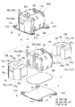
- the reactor which concerns on Embodiment 1 is shown, the upper figure is a schematic perspective view, and the lower figure is a disassembled perspective view.
- the core member which concerns on the modified example 1-1 is shown, the left figure is the schematic perspective view seen from the outer end surface side, and the right figure is the schematic perspective view seen from the linkage surface side.
- the core member which concerns on Embodiment 2 is shown, the left figure is the schematic perspective view seen from the outer end surface side, and the right figure is the schematic perspective view seen from the linkage surface side.
- the reactor which concerns on Embodiment 2 is shown, the upper figure is a schematic perspective view, and the lower figure is a disassembled perspective view.
- the core member which concerns on Embodiment 3 is shown, the left figure is the schematic perspective view seen from the outer end surface side, and the right figure is the schematic perspective view seen from the linkage surface side.
- the reactor which concerns on Embodiment 3 is shown, the upper figure is a schematic perspective view, and the lower figure is a disassembled perspective view.
- the core member according to the embodiment is formed by molding a mixture containing soft magnetic powder and resin.
- This core member has, as a specific surface, a specific portion having at least one of an installation surface facing the object to be installed of the core member and an interlinkage surface where magnetic flux excited by the coil intersects, opposite to the opposite side of the specific surface And a surface.
- the density of a specific part is high density compared with the density of the vicinity of an opposite surface.
- the required characteristics can be satisfactorily handled. This is because if the specific part has the installation surface as the specific surface, since the installation surface side contains a lot of soft magnetic powder, the thermal conductivity can be improved and the heat dissipation characteristics of the core member can be improved through the installation surface. Also, if the specific part has a linkage surface as a specific surface, it contains a lot of soft magnetic powder on the side of the linkage surface, so the magnetic permeability can be increased and the magnetic flux of the core member can be reduced by reducing the leakage flux at the linkage surface. It is because it can improve. When the specific part has both the installation surface and the interlinking surface as the specific surface, both the heat dissipation characteristics and the magnetic characteristics can be improved.
- the core member is formed by injecting the mixture into the mold from the gate, and is formed on the gate surface that is unevenly distributed on the opposite side to the specific surface of the outer surface of the core member. It may be provided with a trace part. The density of the specific part is higher than the density in the vicinity of the trace part.
- the trace portion of the gate is unevenly distributed on the side opposite to the specific surface, so that the trace portion of the gate is formed at a location away from the specific location, so that the specific location is increased.
- the core member is manufactured by filling the mixture into the cavity from the gate of the mold as described above, and then solidifying (curing) the resin. Conventionally, the required characteristics of the core member are improved and the gate is formed. The relationship with the position of was not studied.
- this inventor analyzed the core member produced by inject
- the specific surface includes the installation surface, and the trace portion is formed on the outer end surface connecting the installation surface and the opposite surface.
- the trace part is formed in the outer end surface which connects an installation surface and its opposite surface,
- the installation surface side edge part of the core member containing an installation surface can be made high-density, and a core member's Heat dissipation characteristics can be improved.
- the specific surface includes a linkage surface, and the trace portion is formed on the opposite surface of the linkage surface.
- the trace part is formed in the opposite surface of a linkage surface, the end part on the linkage surface side of the core member containing a linkage surface can be made high-density, and the magnetic characteristic of a core member can be improved. It can be improved.
- a base portion and a pair of overhang portions may be provided.
- the base has an installation surface, an opposite surface thereof, and an outer end surface connecting the installation surface and the opposite surface.
- the overhanging portion has an interlinkage surface opposite to the outer end surface, and protrudes from the base portion in a direction parallel to the installation surface and is inserted into the coil.
- the trace portion is preferably provided on the opposite surface side of the outer end surface.
- the trace portion is provided on the opposite surface side of the outer end surface, so that the linkage surface side end portion including the linkage surface and the installation surface side end portion including the installation surface are respectively increased. Since the density can be increased, the magnetic characteristics and heat dissipation characteristics can be improved.
- a base portion As one form of the core member provided with a trace portion, a base portion, an inner overhang portion, and an outer overhang portion may be provided.
- the base has an installation surface, an opposite surface thereof, and an outer end surface connecting the installation surface and the opposite surface.
- the inner overhanging portion has an interlinkage surface opposite to the outer end surface, and protrudes from the base portion in a direction parallel to the installation surface and is inserted into the coil.
- the outer overhanging portion protrudes in a direction parallel to the installation surface from the base with the inner overhanging portion sandwiched between the outer periphery of the coil.
- the trace portion is preferably provided on the opposite surface side of the outer end surface.
- the trace part is provided in the other surface side among the outer end surfaces, and thereby the linkage surface side end portion including the linkage surface and the installation surface side end portion including the installation surface are each dense. Therefore, magnetic characteristics and heat dissipation characteristics can be improved.
- the core member including a trace portion, an outer end surface that connects the installation surface and the opposite surface thereof is provided, and the trace portion is 2/3 of the distance from the installation surface to the opposite surface of the outer end surface. It is mentioned that it is formed on the opposite surface side from the position.
- the trace portion is formed at the above position, so that the specific portion can be further dense.
- the reactor according to the embodiment includes a coil formed by winding a winding and a magnetic core on which the coil is arranged. At least a part of the magnetic core is the core member according to any one of (1) to (7) above.
- the required characteristics such as magnetic characteristics and heat dissipation characteristics are excellent by providing the core member described above.
- the manufacturing method of the core member according to the embodiment includes a step of injecting a mixture containing soft magnetic powder and resin into the mold from the gate and curing the resin to form the core member.
- the mold is a specific inner peripheral surface that forms a specific surface that is at least one of an installation surface that faces the installation target of the core member and a magnetic flux excited by a coil, among the surfaces of the core member, And an opposite inner peripheral surface forming an opposite surface opposite to the specific surface.
- die is unevenly distributed in the opposite inner peripheral surface side with respect to a specific inner peripheral surface.
- the specific portion can be made dense by setting the position of the gate in the mold to be a portion away from the specific portion including the specific surface.
- the core member has an installation surface, an opposite surface thereof, and an outer end surface connecting the installation surface and the opposite surface, and the gate corresponds to the outer end surface. It is mentioned that it is provided at the position to be.
- the core member has an interlinkage surface and an opposite surface thereof, and the gate is provided at a position corresponding to the opposite surface.
- a core member is provided with the base and a pair of overhang
- the base has an installation surface, an opposite surface thereof, and an outer end surface connecting the installation surface and the opposite surface.
- the pair of overhang portions have interlinkage surfaces opposite to the outer end surfaces, and protrude from the base portion in a direction parallel to the installation surface and are inserted into the coil.
- the core member having excellent magnetic characteristics and heat dissipation characteristics by increasing the density of the linkage surface side end including the linkage surface and the installation surface side end including the installation surface.
- a core member is provided with a base, an inner side overhang
- the base has an installation surface, an opposite surface thereof, and an outer end surface connecting the installation surface and the opposite surface.
- the inner overhanging portion has an interlinkage surface opposite to the outer end surface, and protrudes from the base portion in a direction parallel to the installation surface and is inserted into the coil.
- the pair of outer overhang portions project from the base in a direction parallel to the installation surface with the inner overhang portion sandwiched between the outer periphery of the coil.
- the core member having excellent magnetic characteristics and heat dissipation characteristics by increasing the density of the linkage surface side end including the linkage surface and the installation surface side end including the installation surface.
- a core member has an installation surface, its opposite surface, an outer end surface which connects an installation surface and its opposite surface, and a gate is an outer end surface. It is mentioned that it is provided at a position corresponding to the opposite surface rather than a position that is 2/3 of the distance from the installation surface to the opposite surface.
- Embodiment 1 The core member according to the embodiment is composed of a composite material including soft magnetic powder and resin.
- This core member is obtained by solidifying (curing) a resin of a mixture containing soft magnetic powder and resin, and typically constitutes at least a part of the magnetic core provided in the reactor.
- the reactor includes, for example, a coil 2A and a magnetic core 1A shown in FIG.
- the coil 2A is formed by connecting a pair of winding portions 20a and 20b, in which the winding 20w is spirally wound, in parallel with each other.
- the magnetic core 1A is configured in an annular shape by combining two core members 10A having the same shape.
- both core members 10A are made of a composite material.
- the core member 10A is manufactured by filling a mold material cavity with a material having fluidity from a gate and solidifying a resin.
- the main feature of the core member 10A is that it includes a specific part that requires heat dissipation characteristics, magnetic characteristics, and the like, and this specific part has a higher density than the vicinity of the opposite surface.
- a description will be given of a mode in which the gate is arranged so that the specific portion has a higher density than the vicinity of the opposite surface, and the specific portion and the trace portion of the gate satisfy a specific positional relationship.
- the core member 10A is assembled to the coil 2A to construct the reactor 100A.
- the core member 10A includes a base portion 11A and a pair of protruding portions 12A protruding from one end surface of the base portion 11A.
- the shape seen from above the core member 10A is substantially U-shaped.
- the base 11A protrudes from the end surface of the coil 2A when the core member 10A is assembled to the coil 2A (FIG. 2).
- the base 11A has a bottom surface 15d g, and the upper surface 15u g, and an outer end face 15o connecting the lower surface 15d g and the upper surface 15u g (the surface opposite to the projecting portion 12A).
- the outer end surface 15o has a flat surface portion located in the center in parallel with the interlinkage surface 15i (described later) of the overhang portion 12A, and inclined portions located on both sides thereof.
- the shape of the base 11A is a substantially trapezoidal columnar shape. Projecting unit 12A, and projects away from the outer end face 15o from the base 11A in the lower surface 15d g a direction parallel when assembled with the core member 10A in the coil 2A, is inserted into the coil 2A.
- the overhanging portion 12A has an interlinkage surface 15i on the side opposite to the outer end surface 15o of the base portion 11A where the magnetic flux excited by the coil 2A intersects.
- the shape of the overhanging portion 12A is a rectangular parallelepiped shape, and the corners thereof are rounded along the inner peripheral surfaces of the winding portions 20a and 20b (FIG. 2).
- lower surface 15d g of the base portion 11A is lower than the lower surface 15d i of Ryohari fat 12A.
- the installation target side of the core member 10A is constituted by a lower surface 15d g of the base portion 11A, to form a mounting surface 15h g of the lower surface 15d g is radiation path of the core member 10A.
- the length of the overhanging portion 12A (the length in the protruding direction with respect to the base portion 11A) is about half the length of the winding portions 20a and 20b.
- the specific part 13 is a part of the core member 10 ⁇ / b> A, and when the core member 10 ⁇ / b> A is used as a magnetic core, the specific part 13 is a part where specific characteristics are significantly required compared to other parts. Specific examples of required characteristics include heat dissipation characteristics and magnetic characteristics. In FIG. 1, the specific part 13 is shown by cross hatching. The specific part 13 has, for example, at least one surface of the installation surface 15h g and the linkage surface 15i as the specific surface 13f in order to achieve required characteristics such as heat dissipation characteristics and magnetic characteristics. The position of the specific part 13 can be appropriately selected according to required characteristics.
- the position of the specific portion 13 include lower end of the base portion 11A including the installation surface 15h g of the base 11A. That way, for the specific portion 13 containing a large amount of metals such as iron, an elevated thermal conductivity, easy to cool the core member 10A via a mounting surface 15h g.
- the lower end portion of the base portion 11A including the installation surface 15h g includes a region from the installation surface 15h g of the base portion 11A to about 1/7 of the height of the base portion 11A.
- the position of the specific portion 13 may be the end portion of the overhanging portion 12A including the linkage surface 15i of the overhanging portion 12A (the end surface facing the other overhanging portion 12A). Then, since the specific part 13 contains many soft magnetic materials, such as iron, magnetic permeability can be high and leakage magnetic flux can be reduced, and a magnetic characteristic can be improved.
- the end portion of the overhang portion 12A including the linkage surface 15i include a region from the linkage surface 15i of the overhang portion 12A to about 1 ⁇ 2 of the length of the overhang portion 12A.
- the position of the specific portion 13 is the lower end portion of the base portion 11A including the installation surface 15h g of the base portion 11A and the overhang portion including the interlinkage surface 15i of the overhang portion 12A.
- Each of the end portions of 12A may be mentioned. That is, when there are a plurality of required characteristics, the specific portion 13 may be located at a plurality of locations accordingly.
- the position of the specific portion 13 has a lower end portion of the base portion 11A including the installation surface 15h g of the base portion 11A (the region from the installation surface 15h g to about 1/7 of the height), the pair of projecting portions 12A The end portion of the overhanging portion 12A including the interlinkage surface 15i (region extending from the interlinkage surface 15i to about 1 ⁇ 2 of the length).
- the specific portion 13 has a higher density than the vicinity of the opposite surface 14 on the opposite side of the specific surface 13f in order to satisfy this required characteristic.
- the opposite surface 14 refers to a surface located on the opposite side of the specific surface 13f across the core member 10A.
- the opposite surface 14 is a surface farthest from the specific surface 13f or the extended surface (longest orthogonal) among the cross surfaces intersecting the orthogonal axis orthogonal to the specific surface 13f or the extended surface of the specific surface 13f on the opposite side of the specific surface 13f. It is preferable to use any one of a plane intersecting the axis) and an adjacent plane adjacent to the far plane.
- the orthogonal axis is a normal line of the specific surface 13f or the extended surface.
- the far surface and the adjacent surface include an inclined surface or a curved surface that is not parallel to the specific surface 13f and a parallel surface that is parallel to the specific surface 13f, but the opposite surface 14 includes the far surface and the curved surface.
- a parallel surface is preferable.
- the vicinity of the opposite surface 14 is a region between the surface including the opposite surface 14 and 1/5 of the distance from the specific surface 13f (linkage surface 15f or installation surface 15h g ). It is preferable that the specific portion 13 has a higher density than the vicinity of the trace portion 16 of the gate.
- the density of the specific portion 13 can be increased by providing the gate arrangement portion at a predetermined position when the core member 10A is molded. Details will be described later.
- the vicinity of the trace portion 16 of the gate is a region between the surface including the trace portion 16 (gate formation surface) and 1/5 of the distance from the gate formation surface to the linkage surface 15i on the opposite side.
- the area including the trace portion 16 is set to be 1/5 of the height of the gate formation surface.
- the width in the vicinity of the trace portion 16 is a region corresponding to the width of the trace portion 16.
- the trace portion 16 of the gate is a portion corresponding to the gate for filling the material of the core member 10A (described later) into the cavity of the mold when the core member 10A is molded.
- the core member 10A can be manufactured by injection molding or MIM (Metal Injection Molding).
- MIM Metal Injection Molding
- an appendage having a portion corresponding to the gate is formed, and the trace portion 16 of the gate is formed by removing the appendage.
- the attachment portion may have a portion corresponding to the sprue, and may further have a portion corresponding to the runner.
- the attachment part can be removed by, for example, breaking the attachment part.
- the trace portion 16 may be subjected to heat treatment after removing the attached portion. When the appendage portion is removed, the trace portion 16 may locally expose the soft magnetic particles as the constituent material. By applying heat treatment, the resin in the vicinity of the surface of the trace portion 16 can flow, and the exposed soft magnetic particles can move from the surface of the resin to the inside along with the flow of the resin to be embedded in the resin. .
- the trace portion 16 is shown in a protruding state with emphasis.
- the trace portion 16 may be flush with the periphery thereof or may protrude beyond the periphery. If the trace portion 16 protrudes from the periphery, the heat treatment is easy to perform, but the protrusion amount may be very small.
- the formation part of the trace part 16 is determined by the position of the specific part 13. This is because the trace portion 16 depends on the position of the gate, and if the gate is provided at a location away from the specific portion 13, the specific portion 13 can be made dense.
- the formation part of the trace part 16 is made into the position which is unevenly distributed in the opposite surface 14 side with respect to the specific surface 13f which the specific site
- To be unevenly distributed on the opposite surface 14 side means a case where it is located on the opposite surface 14 or on a surface other than the opposite surface 14 and located closer to the opposite surface 14 side than the specific surface 13f.
- the location of the trace portion 16 is determined to be unevenly distributed on the opposite surface 14 side with respect to the specific surface 13f.
- the part 13 can be made denser than the vicinity of the trace part 16.
- the trace portion 16 is formed on the upper surface of the base 11A that is opposite to the interlinkage surface 15i. It is preferable that it is at least one of 15u g , the installation surface 15h g , and the outer end surface 15o (opposite surface 14 of the linkage surface 15i). That is, during molding of the core member 10A, the upper surface 15u g of the area where the base portion 11A of the traces 16, installation surface 15h g, and it is preferable to provide a gate so that the outer end face at least one surface of 15o.
- projection part 12A containing the interlinkage surface 15i can be made high-density.
- the formation portion of the trace portion 16 is preferably the outer end surface 15o of the base portion 11A, and among them, a plane portion parallel to the interlinkage surface 15i is preferable in the outer end surface 15o. That is, the opposite surface 14 is preferably a flat portion of the outer end surface 15o. This is because if the trace portion 16 is formed at the outer end face 15o, the core member 10A can be easily assembled to the coil 2A, and the core member 10A can be easily installed on the installation target.
- the formation part of the trace part 16 may be on the axis of symmetry of the specific parts 13.
- the core member 10A of FIG. 1 includes a pair of overhang portions 12A, and the specific portion 13 is formed at the end of each overhang portion 12A.
- the formation part of the trace part 16 into the approximate center between specific parts 13 among the outer end surfaces 15o. That is, the opposite surface 14 is preferably a flat portion of the outer end surface 15o. If it does so, all of the specific parts 13 of a symmetrical position can be made into about the same high density.
- the specific portion 13 located in the lower end of the base portion 11A if it contains installation surface 15h g as a specific surface 13f, the area where the traces 16, the upper surface 15u g of the base 11A is opposite to the installation surface 15h g, and it is preferably at least one of an upper surface 15u g side of the outer end face 15o of the base 11A (1/2 than a position of the distance from the installation surface 15h g to an upper surface 15u g). That way, possible specific site 13 is a lower end of the base portion 11A including the installation surface 15h g high density.
- each of the specific portion 13 comprises a mounting surface 15h g and chain ⁇ 15i as the specific surface 13f, traces 16 the area where the upper surface 15u g of the base 11A is opposite to the both sides of the installation surface 15h g and chain ⁇ 15i, and the upper surface 15u g side of the outer end face 15o of the base 11A is preferred. That way, it and the lower end portion of the base portion 11A including the installation surface 15h g, and an end portion of the projecting portion 12A comprising a chain ⁇ 15i high density. In particular, the area where the traces 16, the upper surface 15u g side of the outer end face 15o of the base 11A is preferred.
- the area where the traces 16 is directed to the upper surface 15u g side of the planar portion at the outer end face 15o of the base 11A (5/7 about a position of the distance from the installation surface 15h g to an upper surface 15u g).
- the shape of the trace part 16 is a ridge extending over the entire length in the width direction of the flat part.
- the width direction refers to the direction in which the two overhang portions 12A are arranged in parallel.
- the trace portion 16 is located at the center in the vicinity of the trace portion 16.
- the formation of the trace portion 16 at a predetermined position can be performed by providing a gate position where the constituent material of the core member 10A is filled in the cavity of the mold at a predetermined position.
- the number of the trace portions 16 is single as shown in FIG. 1, but may be plural. In the case of a plurality, it is mentioned that the mutual positional relationship is about the same with respect to the specific part 13.
- the shape of the trace portion 16 is an elongated rectangular parallelepiped as shown in FIG. 1, but if the surface on which the trace portion 16 is formed is a curved surface, the shape of the trace portion 16 may be an arc-shaped protrusion. Good.
- Soft magnetic powder examples include iron-based materials such as iron and iron alloys.
- iron alloys include Fe—Si alloys, Fe—Al alloys, Fe—N alloys, Fe—Ni alloys, Fe—C alloys, Fe—B alloys, Fe—Co alloys, Fe—P. Alloy, Fe—Ni—Co alloy, Fe—Al—Si alloy and the like.
- Other examples include non-metallic materials such as ferrite. In particular, from the viewpoint of magnetic permeability and magnetic flux density, pure iron in which 99% by mass or more is Fe is preferable.
- the average particle size of the soft magnetic powder is preferably 1 ⁇ m or more and 1000 ⁇ m or less, particularly preferably 10 ⁇ m or more and 500 ⁇ m or less.
- the soft magnetic powder may be a mixture of a plurality of types of powders having different particle sizes. When a soft magnetic powder in which a fine powder and a coarse powder are mixed is used as the material for the core member, a saturation magnetic flux density is high and a low-loss reactor is easily obtained.
- the content of the soft magnetic powder in the composite material may be 30% by volume or more and 85% by volume or less when the composite material is 100% by volume.
- the soft magnetic powder is 30% by volume or more, the specific portion 13 can be easily densified.
- the ratio of the magnetic component is sufficiently high, when the reactor 100A is constructed using the core member 10A, it is easy to increase the saturation magnetic flux density.
- the soft magnetic powder is 85% by volume or less, the fluidity of the mixture of the soft magnetic powder and the resin is excellent, and the core member 10A is excellent in manufacturability.
- the content of the soft magnetic powder is 50% by volume or more, further 55% by volume or more, particularly 60% by volume or more.
- the content of the soft magnetic powder when the content of the soft magnetic powder is 60% by volume or more, it is effective to mold the core member 10A by providing the gate at a position away from the specific portion 13 as described above. This is because if the content of the soft magnetic powder is high, the density tends to be uneven.
- the content of the soft magnetic powder is 80% by volume or less, 75% by volume or less, particularly 70% by volume or less.
- thermosetting resins such as epoxy resin, phenol resin, silicone resin, and urethane resin
- PPS polyphenylene sulfide
- polyamide resin for example, nylon 6, nylon 66, nylon 9T
- LCP liquid crystal polymer
- Thermoplastic resins such as polyimide resins and fluororesins.
- a room temperature curable resin, BMC (Bulk molding compound) in which calcium carbonate or glass fiber is mixed with unsaturated polyester, millable silicone rubber, millable urethane rubber, or the like can also be used.
- the composite material may contain a powder (filler) made of a nonmagnetic material such as ceramics such as alumina or silica.
- a filler contributes to the improvement of heat dissipation.
- the content of the filler is preferably 0.2% by mass or more and 20% by mass or less, more preferably 0.3% by mass or more and 15% by mass or less, particularly 0.5% by mass or more, when the composite material is 100% by mass. 10 mass% or less is preferable.
- the core member 10A can be manufactured by injection molding or MIM as described above.
- injection molding the above-mentioned soft magnetic powder and the above-mentioned resin in a fluid state are mixed, and this mixture is molded by pouring into a molding die having a predetermined shape under a predetermined pressure. Thereafter, the resin is cured (solidified). Also in the case of MIM, the mixture is filled in a molding die for molding.
- the mold not shown, of the surface of the core member 10A, a particular inner circumferential surface of forming at least one to become a specific surface 13f of the installation surface 15h g and chain ⁇ 15i, opposite the specific surface 13f And an opposite inner peripheral surface forming the opposite surface 14 on the side.
- the position of the gate in the mold is unevenly distributed on the opposite inner peripheral surface side with respect to the specific inner peripheral surface, and can be appropriately selected according to a desired position of the specific portion 13 having a high density.
- Position of the gate for example, of the surface of the core member 10A, include placing surface 15h g and the opposite surface 14 (upper surface 15u g) and a position corresponding to the outer end face 15o connecting.
- the core member 10A in which the specific surface 13f includes the installation surface 15h g that is, the core that includes a large amount of soft magnetic powder on the installation surface 15h g side, can improve the thermal conductivity of the installation surface 15h g , and has excellent heat dissipation characteristics. It is easy to manufacture the member 10A.
- the position of a gate is mentioned as the position corresponding to the surface 14 (outer end surface 15o) opposite to the linkage surface 15i among the surfaces of the core member 10A, for example.
- the core member 10A in which the specific surface 13f includes the linkage surface 15i that is, the core member that includes a lot of soft magnetic powder on the linkage surface 15i side, can reduce the leakage magnetic flux on the linkage surface 15i, and has excellent magnetic properties. 10A can be manufactured.
- the core member 10A including the base portion 11A and the pair of projecting portions 12A, and the specific portion 13 having both the interlinkage surface 15i and the installation surface 15h g is used to install the base portion 11A.
- the position of the gate and more preferably in a position corresponding to the opposite surface 14 side than 2/3 a position of the distance to the opposite surface 14 from the installation surface 15h g of the outer end surface 15o.
- the position of the gate is in a position corresponding to the position where the order of 5/7 of the distance from the installation surface 15h g of the outer end face 15o to the opposite surface 14.
- the gate trace portion 16 is unevenly distributed on the opposite surface 14 side with respect to the specific surface 13f, and the gate trace portion 16 is formed at a location away from the specific portion 13.
- the specific portion 13 can be made higher in density than the vicinity of the opposite surface 14 (the vicinity of the gate trace portion 16). Since the specific part 13 has the installation surface 15h g of the base portion 11A as the specific surface 13f, since the installation surface 15h g contains a large amount of soft magnetic powder, the thermal conductivity can be increased, and the core is interposed via the installation surface 15h g. The heat dissipation characteristics of the member 10A can be improved.
- the specific portion 13 has the interlinkage surface 15i as the specific surface 13f, since the soft magnetic powder is included on the interlinkage surface 15i side, the magnetic permeability can be increased and the leakage magnetic flux on the interlinkage surface 15i can be reduced. Thus, the magnetic properties of the core member 10A can be improved. Therefore, the core member 10A can cope with required characteristics.
- the core member 10A described above can be suitably used for the magnetic core 1A of the reactor 100A shown in FIG.
- the reactor 100A includes the coil 2A including the pair of winding portions 20a and 20b and the magnetic core 1A including the two core members 10A having the same shape.
- FIG. 2 cross-hatching indicating the specific portion 13 is omitted.
- the specific portion 13 includes the lower end portion of the base portion 11 ⁇ / b> A including the installation surface 15 h g and the interlinkage surface 15 i as in the above-described portion. It is located at the end of the overhanging portion 12A.
- the pair of winding portions 20a and 20b is formed by spirally winding one continuous winding 20w having no joint portion, and is connected via a connecting portion 20r.
- a coated wire having an insulating coating made of an insulating material on the outer periphery of a conductor such as a flat wire or a round wire made of a conductive material such as copper, aluminum, or an alloy thereof can be suitably used.
- the conductor is made of a flat rectangular wire made of copper
- the insulating covering is made of a coated rectangular wire made of enamel (typically polyamideimide).
- Each winding part 20a, 20b is comprised by the edgewise coil which made this covering flat wire the edgewise winding.
- the winding portions 20a and 20b are arranged in parallel (side by side) so that the respective axial directions are parallel to each other.
- the shape of the winding parts 20a and 20b is a hollow cylindrical body (square cylinder) having the same number of turns.
- the end surface shape of the winding parts 20a and 20b is a shape obtained by rounding the corners of the rectangular frame.
- the connecting portion 20r is formed by bending a part of the winding in a U shape on one end side (the right side in FIG. 2) of the coil 2A.
- the upper surface of the connecting portion 20r is substantially flush with the upper surface of the turn forming portion of the coil 2A.
- Both end portions 20e of the winding 20w of the winding portions 20a and 20b are extended from the turn forming portion. Both end portions 20e are connected to a terminal member (not shown), and an external device (not shown) such as a power source for supplying power to the coil 2A is connected through the terminal member.
- reactor 100A can include a heat radiating plate 4 that radiates heat from combination 110A.
- the heat radiating plate 4 is formed of a rectangular plate-like member having a size capable of contacting the entire installation surface of the combined body 110A including the coil 2A and the magnetic core 1A. Therefore, reactor 100A is able to transmit the heat of coil 2A and magnetic core 1A to the installation target.
- the specific portion 13 including the installation surface 15h g of the base portion 11A of each core member 10A has a high density, the heat of the magnetic core 1A can be easily transmitted to the installation target via the heat sink 4.
- the thickness of the heat sink 4 can be selected as appropriate, for example, about 2 mm or more and 5 mm or less.
- a material having excellent thermal conductivity such as a metal such as aluminum or an alloy thereof or a non-metal such as alumina can be used.
- the heat sink 4 and the combined body 110 ⁇ / b> A can be fixed by the bonding layer 5, for example.
- the bonding layer 5 is interposed on at least the installation surface of the coil 2A among the installation surfaces of the combined body 110A.
- the coil 2 ⁇ / b> A can be firmly fixed to the heat sink 4 when the installation target or the above-described heat sink 4 is provided, the movement of the coil 2 ⁇ / b> A is restricted, the heat dissipation is improved, the installation target or the heat sink The stability of fixing to 4 can be achieved.
- the size of the bonding layer 5 is such that it is interposed on the entire installation surface of the combined body 110A.
- the constituent material of the bonding layer 5 contains an insulating resin, particularly a ceramic filler, and has excellent heat dissipation (for example, thermal conductivity is 0.1 W / m ⁇ K or more, further 1 W / m ⁇ K or more, In particular, 2 W / m ⁇ K or more) is preferable.
- the resin include thermosetting resins such as epoxy resin, silicone resin, and unsaturated polyester, and thermoplastic resins such as PPS resin and LCP.
- the specific portion 13 is located at the end of the overhanging portion 12A, includes the linkage surface 15i as the specific surface 13f, and the trace portion 16 is the installation surface of the base portion 11A.
- it can be a core member 10A located in the 15h g. Since the trace portion 16 is positioned on the installation surface 15h g of the base portion 11A, the specific portion 13 which is the end portion of the overhang portion 12A including the interlinkage surface 15i has a higher density than the vicinity of the trace portion 16 of the gate.
- the member 10A can be used.
- Shape trace section 16 is a ridge along the length of the long base of the installation surface 15h g trapezoidal.
- the vicinity of the trace section 16, from the surface (gate formation plane) including trace portion 16, between the 1/5 of the distance of the gate-forming surface and to the upper surface 15u g of opposite This is an area. That is, the vicinity of the trace section 16 includes an installation surface 15h g whole surface.
- the other configuration of the core member 10A is the same as that of the core member 10A of the first embodiment, except for the specific site 13 and the trace portion 16 formation site.
- the preparation of the core member 10A include is possible to position of the gate as the position corresponding to the installation surface 15h g of the core member 10A.
- the reactor including the core member 10A is the same as the reactor 100A according to the first embodiment except for the formation of the specific portion 13 and the trace portion 16 in the core member 10A. Omitted.
- the core member 10A of Modification 1-1 by traces 16 are formed on the installation surface 15h g of the base 11A, a specific site is an end of the protruding portion 12A comprising a chain ⁇ 15i 13 Can be made dense. Therefore, leakage magnetic flux can be reduced and magnetic characteristics can be improved. Since the reactor 100A includes the core member 10A, the reactor 100A is excellent in magnetic characteristics.
- Embodiment 2 >> In the first embodiment and the modified example 1-1, the U-side core member 10A including the base portion 11A and the pair of protruding portions 12A and the reactor 100A including the core member 10A have been described (FIGS. 1 to 3).
- an E-type core member 10B including a base portion 11B, an inner overhang portion 12B i, and a pair of outer overhang portions 12B s will be described first with reference mainly to FIG. Then, with reference to FIG. 5, the reactor 100B provided with this core member 10B is demonstrated.
- the configuration different from the first embodiment will be mainly described, and the description of the same configuration and effect as those of the first embodiment will be omitted. This also applies to Embodiment 3 described later.
- the base 11B protrudes from the end surface of the coil 2B when the core member 10B is assembled to the coil 2B (FIG. 5), similarly to the base 11A of the first embodiment.
- the base 11B has a lower surface 15d g, and the upper surface 15u g, and an outer end face 15o connecting the lower surface 15d g and the upper surface 15u g.
- the outer end surface 15o has a plane portion parallel to the inner linkage surface 15i i (described later) of the inner overhang portion 12B i .
- the shape of the base 11B is a thin prismatic body.
- the inner overhanging portion 12B i protrudes from the base portion 11B in a direction parallel to the lower surface 15d g and away from the outer end surface 15o, and is inserted into the coil 2B when the core member 10B is assembled to the coil 2B.
- the inner overhanging portion 12B i has an inner interlinking surface 15i i on the opposite side of the outer end surface 15o of the base portion 11B, in which the magnetic flux excited by the coil 2B is orthogonal.
- Shape of the inner projecting portion 12B i is a rectangular parallelepiped, the corner portions are rounded as along the inner peripheral surface of the winding portion 20c (FIG. 5).
- Outside protruding portion 12B s is the outer periphery of the coil 2B, projecting from the base portion 11B across the inner projecting portion 12B i to the lower surface 15d g parallel directions. Outside protruding portion 12B s is opposite the outer end face 15o of the base 11B, has an outer chain ⁇ 15i s magnetic flux is excited by the coil 2B are orthogonal, and a lower surface 15d s.
- the shape of the outside protruding portion 12B s is a thin rectangular column shape.
- each of the upper surface 15u g of the base 11B and the outer projecting portion 12B s, 15u s together, each of the lower surface 15d g, 15d s together are flush. These top 15u g, 15u s is higher than the upper surface 15u i of the inner projecting portion 12B i, these lower surface 15d g, 15d s is lower than the lower surface 15d i of the inner projecting portion 12B i.
- the lower surface 15d g of the base portion 11B and an outer overhanging portion 12B s, 15d s is the lower surface flush with the coil 2B.
- the installation target side of the core member 10B is composed of the lower surface 15d s of the lower surface 15d g and a pair of outer projecting portion 12B s base 11B, heat dissipation path of the lower surface 15d g and the lower surface 15d s and a core member 10B
- An installation surface 15h g and an installation surface 15h s are formed.
- the length of the outer projecting portion 12B s (length of the projecting direction with respect to the base 11B), a length of about half of the winding portion 20c, the length of the inner projecting portion 12B i is outside protruding portion 12B Slightly shorter than s .
- End of the outer projecting portion 12B s is a region from the outer chain ⁇ 15i s to approximately 1/2 of the length of the outer projecting portion 12B s.
- the lower end of the outer projecting portion 12B s is an area from the installation surface 15h s to about 1/2 of the height of the outside protruding portions 12B s.
- the area where the traces 16, and the upper surface 15u g side of the outer end face 15o of the base 11B (5/7 about a position of the distance from the installation surface 15h g to an upper surface 15u g). If it does so, the said specific part 13 can be densified.
- the shape of the trace portion 16 is a ridge extending over the entire length in the width direction of the outer end surface 15o of the base portion 11B.
- the width direction refers to a direction in which both the outside protruding portion 12B s are parallel.
- Production of the core member 10B is the position of the gate, and be performed as the opposite surface 14 (upper surface 15u g) corresponding to the side position of the installation surface 15h g of the outer end face 15o of the base 11B.
- Position of the gate, as well as the production of the core member 10A of the first embodiment the position corresponding to the opposite surface 14 side than 2/3 a position of the distance to the opposite surface 14 from the installation surface 15h g of the outer end face 15o More preferably.
- the position of the gate is in a position corresponding to the position where the order of 5/7 of the distance from the installation surface 15h g of the outer end face 15o to the opposite surface 14.
- the reactor 100B includes a combination 110B of a coil 2B including one winding portion 20c and a magnetic core 1B including two core members 10B having the same shape.
- the winding part 20c is configured by spirally winding one continuous winding 20w having no joint part. Both end portions 20e of the winding 20w are arranged on one end side of the coil 2B. Specifically, one end 20e of the winding 20w is drawn out in the radial direction of the coil 2B at one end of the coil 2B, and the other end 20e of the winding 20w is directed from the other end of the coil 2B toward one end. And bent so that it is further drawn out in the radial direction of the coil at one end side. Thus, since the both ends 20e of the coil
- each core member 10B When the core member 10B is assembled to the coil 2B, the base portion 11B of each core member 10B is disposed so as to protrude from the end surface of the coil 2B as in the core member 10A of the first embodiment.
- the inner overhang portion 12B i of each core member 10B is disposed inside the winding portion 20c, and the outer overhang portion 12B s of each core member 10B is disposed on the outer periphery of the winding portion 20.
- Coupling between the core member 10B is, for example, performed by connecting the outer chain ⁇ 15i s between the outside protruding portion 12B s with an adhesive. At this time, the air gap is formed between the adjacent inner projecting portion 12B i.
- a specific portion 13 including an inner chain ⁇ 15i i, outer interlinked a specific portion 13 including the surface 15i s can each high density. Therefore, magnetic characteristics can be improved by reducing leakage magnetic flux. Also, possible specific portion 13 including the installation surface 15h S of the outer projecting portion 12B s a high density. Therefore, heat dissipation characteristics can be improved. Since the reactor 100B includes the core member 10B, the reactor 100B is excellent in magnetic characteristics and heat dissipation characteristics.
- Embodiment 3 In the first embodiment and the modified example 1-1, the reactor including the U-shaped core member and the U-shaped core member is described, and in the second embodiment, the reactor including the E-shaped core member and the E-shaped core member is described.
- a core member 10C having a columnar body whose upper surface and lower surface are substantially dome-shaped (a deformed trapezoidal shape in which the cross-sectional area decreases outward from the interlinkage surface) will be described mainly with reference to FIG. To do. Then, with reference to FIG. 7, the reactor 100C provided with the core member 1C will be described.
- the core member 10C protrudes (exposes) from the end surface of the coil 2A when assembled to the coil 2A.
- the core member 10C has a mounting surface 15h g, and the upper surface 15u g, and an outer end face 15o connecting the installation surface 15h g and the upper surface 15u g, and the inner end surface of the magnetic flux that is excited by the coil 2A comprises a chain ⁇ 15i crossing It consists of
- the outer end surface 15o has a flat portion located in the center in parallel with the linkage surface 15i and curved portions located on both sides thereof.
- Upper surface 15u g of the core member 10C is when combined with other core member (inner core portion 31) and the coil 2A (Fig.
- the lower surface 15d g of the core member 10C is lower than the lower surface of the inner core portion 31, and is flush with the lower surface of the coil 2A. That is, the installation target side surface of the core member 10C is configured by the lower surface 15d g , and the lower surface 15d g forms an installation surface 15h g that serves as a heat dissipation path for the core member 10C.
- Examples of the position of the specific portion 13 include the lower end portion of the core member 10C including the installation surface 15h g and the end portion of the core member 10C including the interlinkage surface 15i. .
- the lower end of the core member 10C including the installation surface 15h g is an area from the installation surface 15h g to about 1/10 of the height of the core member 10C.
- the end of the core member 10C including the linkage surface 15i is a region up to about 1/20 of the distance from the linkage surface 15i to the linkage surface 15i and its opposite surface 14 (outer end surface 15o).
- the area where the traces 16 of the gate is in the upper surface 15u g side of the outer end surface of the core member 10C 15o (flat portion).
- the shape of the trace part 16 is a ridge extending over the entire length in the width direction of the flat part.
- the width direction refers to a direction in which both inner core portions 31 are arranged in parallel.
- Production of the core member 10C include is possible to position of the gate as the position corresponding to the upper surface 15u g side of the outer end surface 15o.
- the reactor 100C includes a combination 110C of a coil 2A having a pair of winding portions 20a and 20b similar to the first embodiment and a magnetic core 1C having a plurality of core members including the core member 10C described above.
- a pair of core members hereinafter referred to as the inner core portion 31
- the inner core portion 31 a pair of core members disposed inside the winding portions 20a and 20b and the winding portions 20a and 20b are not disposed. It has a pair of core members 10C protruding (exposed) from the turning portions 20a and 20b.
- the magnetic core 1 ⁇ / b> C includes a linkage surface 15 i (inner end surface) of one core member 10 ⁇ / b> C and one end surface of the pair of inner core portions 31, 31, and a linkage surface 15 i of the other core member 10 ⁇ / b> C and a pair of inner core portions 31. , 31 on the other end face are joined together in a ring shape.
- an annular closed magnetic circuit is formed.
- Each of the inner core portions 31 and 31 is a columnar body having an outer shape along the inner peripheral shape of each of the winding portions 20a and 20b (here, a shape obtained by rounding corners of a rectangular parallelepiped (the lower diagram in FIG. 7)).
- each of the core members 10C and 10C is a columnar body having a substantially dome-shaped upper surface and lower surface.
- the inner core portions 31 and 31 are laminated bodies in which a plurality of core pieces 31m and gap members 31g made of a material having a lower magnetic permeability than the core pieces 31m are alternately laminated. At least one of the core pieces 31m of the inner core portions 31 and 31 can be made of the composite material described above.
- the reactor 100C of the third embodiment since the traces 16 are formed on the upper surface 15u g side of the outer end face 15o of the core member 10C, a specific portion 13 comprising a chain ⁇ 15i, installation surface 15h g The specific portions 13 including can be made dense. Therefore, magnetic characteristics and heat dissipation can be improved. Since the reactor 100C includes the core member 10C, the reactor 100C is excellent in magnetic characteristics and heat dissipation characteristics.
- a core member was prepared by injecting a mixture containing soft magnetic powder and resin into the mold from the gate, and the core member was divided into a plurality of portions, and the density of each portion was measured.
- Sample No. 1 Sample No. As shown in FIG. 8, three U-shaped core member samples each including the base portion and the pair of overhang portions described in the first embodiment and the modified example 1-1 were manufactured as one core member.
- the gate When producing a core member, the gate was provided so that the formation location of the trace part of the gate in the obtained core member might become the lower surface of a core member.
- Sample No. 2 Sample No. As two core members, as shown in FIG. 9, three samples of E-type core members each including the base portion, the inner overhang portion, and the pair of outer overhang portions described in the second embodiment were manufactured.
- the gate When producing a core member, the gate was provided so that the formation part of the trace part of the gate in the obtained core member might become the approximate center of height among the outer end surfaces of a core member.
- Sample No. As shown in FIG. 8, the samples 1 to 3 of 1 are divided into three parts in the height direction, and the overhanging part is equally divided into two in the projecting direction and the height direction. Divided pieces were prepared. A portion from the bottom surface of the base portion to the bottom surface of the overhang portion including the gate of the base portion is designated as No. 1, the part No. No. 1 is the lower half of the height direction in the height direction. 2, the top half of the top side It was set to 3. In addition, the base side and lower surface side portions of both overhang portions are respectively No. Nos. 4, 5 and No. Nos. 6, 7 and No. on the interlinkage surface (end surface) side and the lower surface side of both overhangs are respectively No. Nos. 8 and 9 and the upper surface portion are No. respectively. 10 and 11.
- Sample No. As shown in FIG. 9, the samples 1 to 3 of 2 are divided into three parts in the height direction, the inner projecting part is equally divided into two in the projecting direction, and the outer projecting part in the projecting direction and the height direction. A total of 13 divided pieces were produced by equally dividing into two in the direction.
- a part including the trace part of the gate (the center part of the height of the outer end face) and having the same length as the inner overhang part in the height direction is No. 1, the part No. No. 1 on the upper surface side. 2, the part No. 1 on the lower surface side. It was set to 3.
- the base side portion of the inner overhanging portion is designated as “No. 4, the base part and the end face side part No. It was set to 9.
- both outer overhang portions are respectively No. Nos. 5, 6 and Nos. Nos. 7 and 8 are provided on the side opposite to the base part of the both outer overhanging parts and on the upper surface side.
- Nos. 10 and 11 and the parts on the lower surface side are No. 12 and 13.
- the results of the density and the average value in 2 are shown in a graph in FIG.
- the vertical axis represents density (g / cm 3 ). 10 and 11, ⁇ indicates the result of sample 1, ⁇ indicates the result of sample 2, ⁇ indicates the result of sample 3, and “black square” indicates the average value of samples 1 to 3.
- FIG. 10 Table 2, and FIG. 1 and sample no. In both cases, there was a difference in density at each site.
- Sample No. 1 for example, the region No. As shown in FIG. It was found that the density tends to be higher than that of parts located near the gate such as 1, 2, 4, and 5.
- sample No. 2 similarly, for example, the region No. As shown in FIGS. 7 to 13, the part farther from the gate, for example, part No. It was found that the density tends to be higher than that of parts located near the gate such as 1 to 3.
- the core member of the present invention includes various in-vehicle converters (typically DC-DC converters) and air conditioner converters mounted on vehicles such as hybrid vehicles, plug-in hybrid vehicles, electric vehicles, and fuel cell vehicles. It can use suitably for the core with which the reactor which can be used for the component of a converter and a power converter is equipped.
- the manufacturing method of the core member of this invention can be utilized suitably for manufacture of the said core member.
- the reactor of the present invention includes various on-vehicle converters (typically DC-DC converters) mounted on vehicles such as hybrid vehicles, plug-in hybrid vehicles, electric vehicles, and fuel cell vehicles, and converters for air conditioners. It can utilize suitably for the component of a converter and a power converter.
Abstract
Description
最初に本発明の実施形態の内容を列記して説明する。
(a)コア部材の各部で密度に差異がある。
(b)コア部材の各部のうち、ゲートから離れた位置が高密度になり易い。
(c)軟磁性粉末の充填率が高く高密度であれば、放熱性の向上や漏れ磁束の低減の観点から好ましい。
(d)放熱性の向上や漏れ磁束の低減など、磁性部材としての特定の特性が求められる箇所をゲートから離れた位置とすれば、その特性が求められる箇所を高密度にできる。
本発明の実施形態の詳細を、以下に図面を参照しつつ説明する。なお、本発明はこれらの例示に限定されるものではなく、特許請求の範囲によって示され、特許請求の範囲と均等の意味および範囲内でのすべての変更が含まれることが意図される。
〔コア部材〕
実施形態に係るコア部材は、軟磁性粉末と樹脂とを含む複合材料で構成される。このコア部材は、軟磁性粉末と樹脂とを含む混合物の樹脂を固化(硬化)したものであり、代表的にはリアクトルに備わる磁性コアの少なくとも一部を構成する。リアクトルは、詳しくは後述するが、例えば、図2に示すコイル2Aと磁性コア1Aとを備える。コイル2Aは、巻線20wを螺旋状に巻回した一対の巻回部20a、20bを互いに並列状態で接続してなる。磁性コア1Aは、同一の形状を有する二つのコア部材10Aを組み合わせて環状に構成される。ここでは、両コア部材10Aとも複合材料で構成される。コア部材10Aは、金型のキャビティ内にゲートから流動性のある状態の構成材料を充填して樹脂を固化して作製する。コア部材10Aの主たる特徴とするところは、放熱特性や磁気特性などが要求される特定部位を備え、この特定部位がその反対面の近傍に比較して高密度である点にある。ここでは、この特定部位がその反対面の近傍に比較して高密度となるようにゲートを配置し、特定部位とゲートの痕跡部とが特定の位置関係を満たす形態を説明する。以下、主として図1を参照してコア部材の詳細を説明する。ここでは、コア部材10Aをコイル2Aに組み付けてリアクトル100Aを構築し、リアクトル100Aを冷却ベースなどの設置対象に設置した際の設置対象側を下、設置対象の反対側を上、上下方向を高さとして説明する。図中の同一符号は同一名称物を示す。
コア部材10Aは、基部11Aと、基部11Aの一端面から突出する一対の張出部12Aとで構成されている。コア部材10Aの上方から見た形状は、略U字状である。基部11Aは、コア部材10Aをコイル2A(図2)に組み付けた際、コイル2Aの端面から突出される。基部11Aは、下面15dgと、上面15ugと、下面15dg及び上面15ugをつなぐ外端面15o(張出部12Aとは反対側の面)とを有する。外端面15oは、張出部12Aの鎖交面15i(後述)と平行で中央に位置する平面部と、その両側に位置する傾斜部とを有する。基部11Aの形状は、略台形柱状である。張出部12Aは、基部11Aから下面15dgと平行な方向で外端面15oから離れる方向に突出して、コア部材10Aをコイル2Aに組み付けた際、コイル2A内に挿入される。張出部12Aは、基部11Aの外端面15oの反対側で、コイル2Aで励磁される磁束が交差する鎖交面15iを有する。張出部12Aの形状は、直方体状であり、その角部が巻回部20a,20b(図2)の内周面に沿うように丸まっている。
特定部位13は、コア部材10Aの一部であって、コア部材10Aを磁心として用いた場合に、特定の特性が他の箇所に比べて顕著に要求される箇所である。求められる特性の具体例としては、放熱特性や磁気特性などが挙げられる。図1では、特定部位13をクロスハッチングで示す。特定部位13は、放熱特性や磁気特性など要求される特性を達成するために特定面13fとして、例えば、設置面15hg、及び鎖交面15iの少なくとも一方の面を有する。特定部位13の位置は、要求される特性に応じて適宜選択できる。
ゲートの痕跡部16は、コア部材10Aの成形時に金型のキャビティ内にコア部材10Aの構成材料(後述)を充填するためのゲートに対応する箇所である。コア部材10Aの製造は、射出成形やMIM(Metal Injection Molding)で行える。これらの手法により作製された成形体には、ゲートに対応する部分を有する付属部が形成され、この付属部を除去することでゲートの痕跡部16が形成される。この付属部は、ゲートに対応する部分の他、スプルーに対応する部分を有することがあり、更にはランナーに対応する部分を有することもある。付属部の除去は、例えば、付属部を折り取ることで行える。
特定部位13が張出部12Aの端部に位置し、特定面13fとして鎖交面15iを含む場合、痕跡部16の形成箇所は、鎖交面15iに対して反対側である基部11Aの上面15ug、設置面15hg、及び外端面15o(鎖交面15iの反対面14)の少なくとも一面であることが好ましい。即ち、コア部材10Aの成形時、この痕跡部16の形成箇所が基部11Aの上面15ug、設置面15hg、及び外端面15oの少なくとも一面となるようにゲートを設けることが好ましい。そうすれば、鎖交面15iを含む張出部12Aの端部である特定部位13を高密度にできる。特に、痕跡部16の形成箇所は、基部11Aの外端面15oが好ましく、中でも外端面15oのうち鎖交面15iと平行な平面部が好ましい。即ち、反対面14は、外端面15oの平面部とすることが好ましい。痕跡部16の形成箇所が外端面15oであれば、コア部材10Aをコイル2Aに組み付け易く、コア部材10Aを設置対象へ設置し易いからである。
特定部位13が基部11Aの下端に位置し、特定面13fとして設置面15hgを含む場合、痕跡部16の形成箇所は、設置面15hgに対して反対側である基部11Aの上面15ug、及び基部11Aの外端面15oの上面15ug側(設置面15hgから上面15ugまでの距離の1/2超となる位置)の少なくとも一方であることが好ましい。そうすれば、設置面15hgを含む基部11Aの下端部である特定部位13を高密度にできる。痕跡部16の形成箇所は、基部11Aの外端面15oのうち上面15ug側とする場合、設置面15hgから上面15ugまでの距離の2/3程度となる位置が好ましく、設置面15hgから上面15ugまでの距離の3/4程度となる位置が特に好ましい。
特定部位13が張出部12Aの端部と基部11Aの下端のそれぞれに位置し、それぞれの特定部位13が特定面13fとして設置面15hgと鎖交面15iとを含む場合、痕跡部16の形成箇所は、設置面15hg及び鎖交面15iの両面に対して反対側である基部11Aの上面15ug、及び基部11Aの外端面15oの上面15ug側が好ましい。そうすれば、設置面15hgを含む基部11Aの下端部と、鎖交面15iを含む張出部12Aの端部とを高密度にできる。特に、痕跡部16の形成箇所は、基部11Aの外端面15oの上面15ug側が好ましい。
(軟磁性粉末)
軟磁性粉末は、例えば、鉄や鉄合金といった鉄基材料が挙げられる。鉄合金としては、Fe-Si系合金、Fe-Al系合金、Fe-N系合金、Fe-Ni系合金、Fe-C系合金、Fe-B系合金、Fe-Co系合金、Fe-P系合金、Fe-Ni-Co系合金、及びFe-Al-Si系合金などが挙げられる。その他、フェライトなどの非金属材料が挙げられる。特に、透磁率及び磁束密度の点からみれば、99質量%以上がFeである純鉄が好ましい。
樹脂は、例えば、エポキシ樹脂、フェノール樹脂、シリコーン樹脂、ウレタン樹脂などの熱硬化性樹脂や、ポリフェニレンスルフィド(PPS)樹脂、ポリアミド樹脂(例えば、ナイロン6、ナイロン66、ナイロン9T)、液晶ポリマー(LCP)、ポリイミド樹脂、フッ素樹脂などの熱可塑性樹脂が挙げられる。その他、常温硬化性樹脂、不飽和ポリエステルに炭酸カルシウムやガラス繊維が混合されたBMC(Bulk molding compound)、ミラブル型シリコーンゴム、ミラブル型ウレタンゴムなどを用いることもできる。
複合材料には、軟磁性粉末及び樹脂に加えて、アルミナやシリカなどのセラミックスといった非磁性材料からなる粉末(フィラー)が含有されていても良い。フィラーは、放熱性の向上に寄与する。フィラーの含有量は、複合材料を100質量%とするとき、0.2質量%以上20質量%以下が好ましく、更に0.3質量%以上15質量%以下が好ましく、特に0.5質量%以上10質量%以下が好ましい。
コア部材10Aの製造は、上述のように射出成形、MIMで行える。射出成形の場合は、上述の軟磁性粉末と流動性のある状態の上述の樹脂とを混合し、この混合物を、所定の圧力をかけて、所定の形状の成形用金型に流し込んで成形した後、上記樹脂を硬化(固化)する。MIMの場合も、上記混合物を成形用金型に充填して成形を行う。
上述のコア部材10Aによれば、ゲートの痕跡部16を特定面13fに対して反対面14側に偏在させて特定部位13から離れた箇所にゲートの痕跡部16が形成されていることで、特定部位13を反対面14の近傍(ゲートの痕跡部16の近傍)に比較して高密度にできる。その特定部位13が特定面13fとして基部11Aの設置面15hgを有することで、設置面15hg側に軟磁性粉末を多く含むため、熱伝導性を高められ、設置面15hgを介してコア部材10Aの放熱特性を向上できる。また、特定部位13が特定面13fとして鎖交面15iを有することで、鎖交面15i側に軟磁性粉末を多く含むため、透磁率を高められ、鎖交面15iでの漏れ磁束を低減してコア部材10Aの磁気特性を向上できる。そのため、このコア部材10Aは要求特性に良好に対応できる。
上述のコア部材10Aは図2に示すリアクトル100Aの磁性コア1Aに好適に利用できる。リアクトル100Aは、実施形態1の冒頭で説明したように、一対の巻回部20a、20bを備えるコイル2Aと、同一の形状を有する二つのコア部材10Aで構成される磁性コア1Aとを備える。図2では、特定部位13を示すクロスハッチングは省略しているが、上述した箇所と同様、即ち、特定部位13は、設置面15hgを含む基部11Aの下端部と、鎖交面15iを含む張出部12Aの端部とに位置している。
一対の巻回部20a、20bは、接合部の無い1本の連続する巻線20wを螺旋状に巻回してなり、連結部20rを介して連結されている。巻線20wは、銅やアルミニウム、その合金といった導電性材料からなる平角線や丸線などの導体の外周に、絶縁性材料からなる絶縁被覆を備える被覆線を好適に利用できる。本例では、導体が銅製の平角線からなり、絶縁被覆がエナメル(代表的にはポリアミドイミド)からなる被覆平角線を利用している。各巻回部20a,20bは、この被覆平角線をエッジワイズ巻きにしたエッジワイズコイルで構成している。巻回部20a、20bの配置は、各軸方向が平行するように並列(横並び)した状態としている。巻回部20a、20bの形状は、互いに同一の巻数の中空の筒状体(四角筒)である。巻回部20a、20bの端面形状は、矩形枠の角部を丸めた形状である。連結部20rは、コイル2Aの一端側(図2紙面右側)において巻線の一部をU字状に屈曲して構成している。連結部20rの上面は、コイル2Aのターン形成部分の上面と略面一である。巻回部20a、20bの巻線20wの両端部20eは、ターン形成部から引き延ばされている。両端部20eは、図示しない端子部材に接続され、この端子部材を介して、コイル2Aに電力供給を行なう電源などの外部装置(図示せず)が接続される。
各コア部材10Aの基部11Aは、コア部材10Aをコイル2Aに組み付けた際、コイル2Aから突出するように配置される。各コア部材10Aの一対の張出部12Aは、同様にコイル2Aに組み付けた際、一対の巻回部20a,20bの内側に配置される。一方と他方のコア部材10Aの張出部12Aの鎖交面15i同士を巻回部20a,20b内で連結することで環状の磁性コア1Aが形成される。このコア部材10A同士の連結により、コイル2Aを励磁したとき、閉磁路を形成し、磁束は鎖交面15iに直交する。コア部材10A同士は、張出部12Aの鎖交面15i同士の間にギャップ材を介在させることなく連結されていてもよいし、ギャップ材を介在させて連結させてもよい。コア部材10A同士の連結には、接着剤を利用できる。コア部材10A同士の間には、隙間(エアギャップ)を設けていてもよい。いずれの場合でも、両コア部材10Aの張出部12Aの鎖交面15iを含む特定部位13が高密度であるため、漏れ磁束を低減できて磁気特性を向上できる。ギャップ材の材質はアルミナや不飽和ポリエステルなどの非磁性材料、PPS樹脂などの非磁性材料と磁性材料(鉄粉など)とを含む混合物などが挙げられる。ギャップ材の厚さやエアギャップの間隔は、2.5mm以下が挙げられる。
リアクトル100Aは、組合体110Aを放熱する放熱板4を備えることができる。放熱板4は、コイル2Aと磁性コア1Aとを含む組合体110Aの設置面全面に接触可能な大きさを有する矩形板状の部材で構成している。そのため、リアクトル100Aは、コイル2Aと磁性コア1Aの熱を設置対象に伝えられる。特に、各コア部材10Aの基部11Aの設置面15hgを含む特定部位13が高密度であることで、放熱板4を介して磁性コア1Aの熱を設置対象により伝え易い。放熱板4の四隅には、放熱板4を設置対象に固定するためのボルト(図示略)などを挿通させる貫通孔41hを有するフランジ部41を設けるとよい。放熱板4の厚さは、適宜選択することができ、例えば、2mm以上5mm以下程度が挙げられる。放熱板4の構成材料は、アルミニウムやその合金といった金属や、アルミナなどの非金属などの熱伝導性に優れるものを利用できる。放熱板4と組合体110Aとの固定は、例えば、接合層5によって行える。
接合層5は、組合体110Aの設置面のうち少なくともコイル2Aの設置面に介在することが挙げられる。接合層5を備えることで、設置対象又は上述の放熱板4を備える場合には放熱板4にコイル2Aを強固に固定でき、コイル2Aの動きの規制、放熱性の向上、設置対象又は放熱板4への固定の安定性などを図ることができる。接合層5の大きさは、組合体110Aの設置面全面に介在される程度としている。接合層5の構成材料は、絶縁性樹脂、特にセラミックスフィラーなどを含有して放熱性に優れるもの(例えば、熱伝導率は、0.1W/m・K以上、更に1W/m・K以上、特に2W/m・K以上)が好ましい。具体的な樹脂は、エポキシ樹脂、シリコーン樹脂、不飽和ポリエステルなどの熱硬化性樹脂や、PPS樹脂、LCPなどの熱可塑性樹脂が挙げられる。
上述のリアクトル100Aによれば、鎖交面15iを含む張出部12Aの端部と設置面15hgを含む基部11Aの下端部がそれぞれ高密度なコア部材10Aを備えることで、磁気特性及び放熱特性に優れる。
変形例1-1として、図3に示すように、特定部位13が張出部12Aの端部に位置して、特定面13fとして鎖交面15iを含み、痕跡部16が基部11Aの設置面15hgに位置するコア部材10Aとすることができる。痕跡部16が基部11Aの設置面15hgに位置することで、鎖交面15iを含む張出部12Aの端部である特定部位13がゲートの痕跡部16の近傍に比べて高密度なコア部材10Aとすることができる。痕跡部16の形状は、台形状の設置面15hgの長底辺の全長に沿った突条である。変形例1-1では、痕跡部16の近傍とは、痕跡部16を含む面(ゲート形成面)から、ゲート形成面とその反対側の上面15ugまでの距離の1/5までの間の領域とする。即ち、痕跡部16の近傍は、設置面15hg全面を含む。このコア部材10Aは、特定部位13及び痕跡部16の形成箇所を除き、その他の構成は実施形態1のコア部材10Aと同様である。このコア部材10Aの製造は、ゲートの位置をコア部材10Aの設置面15hgに対応する位置として行うことが挙げられる。また、このコア部材10Aを備えるリアクトルも同様、コア部材10Aにおける特定部位13及び痕跡部16の形成箇所を除き、その他の構成は、実施形態1のリアクトル100Aと同様であるため、説明と共に図示を省略する。変形例1-1のコア部材10Aによれば、痕跡部16が基部11Aの設置面15hgに形成されていることで、鎖交面15iを含む張出部12Aの端部である特定部位13を高密度にできる。そのため、漏れ磁束を低減できて磁気特性を向上できる。リアクトル100Aは、このコア部材10Aを備えるため、磁気特性に優れる。
実施形態1、変形例1-1では、基部11Aと一対の張出部12Aとを備えるU側のコア部材10A及びそのコア部材10Aを備えるリアクトル100Aを説明した(図1~3)。実施形態2では、まず、主として図4を参照して、基部11Bと内側張出部12Biと一対の外側張出部12Bsとを備えるE型のコア部材10Bを説明する。その後、図5を参照して、このコア部材10Bを備えるリアクトル100Bを説明する。以下の説明は、実施形態1と相違する構成を中心に説明し、実施形態1と同様の構成及び効果の説明は省略する。この点は、後述の実施形態3でも同様である。
[全体構成]
基部11Bは、実施形態1の基部11Aと同様、コア部材10Bをコイル2B(図5)に組み付けた際、コイル2Bの端面から突出される。基部11Bは下面15dgと、上面15ugと、下面15dg及び上面15ugをつなぐ外端面15oとを有する。外端面15oは、内側張出部12Biの内側鎖交面15ii(後述)と平行な平面部を有する。基部11Bの形状は、薄い角柱体状である。内側張出部12Biは、基部11Bから下面15dgと平行な方向で外端面15oから離れる方向に突出し、コア部材10Bをコイル2Bに組み付けた際、コイル2B内に挿入される。内側張出部12Biは、基部11Bの外端面15oの反対側で、コイル2Bで励磁される磁束が直交する内側鎖交面15iiを有する。内側張出部12Biの形状は、直方体状であり、その角部が巻回部20c(図5)の内周面に沿うように丸まっている。外側張出部12Bsは、コイル2Bの外周で、内側張出部12Biを挟んで基部11Bから下面15dgと平行な方向に突出する。外側張出部12Bsは、基部11Bの外端面15oの反対側で、コイル2Bで励磁される磁束が直交する外側鎖交面15isと、下面15dsとを有する。外側張出部12Bsの形状は、薄い角柱体状である。
特定部位13の位置は、実施形態1と同様、基部11Bの設置面15hgを含む基部11Bの下端部、外側張出部12Bsの設置面15hsを含む外側張出部12Bsの下端部、内側鎖交面15iiを含む内側張出部12Biの端部、及び外側鎖交面15isを含む外側張出部12Bsの端部が挙げられる。ここでは、特定部位13の位置は、内側鎖交面15iを含む内側張出部12Biの端部と、外側鎖交面15isを含む外側張出部12Bsの端部と、外側張出部12Bsの設置面15hsを含む外側張出部12Bsの下端部としている。内側張出部12Biの端部は、内側鎖交面15iiから、内側張出部12Biの長さの1/2程度までの領域である。外側張出部12Bsの端部は、外側鎖交面15isから外側張出部12Bsの長さの1/2程度までの領域である。外側張出部12Bsの下端部は、設置面15hsから外側張出部12Bsの高さの1/2程度までの領域である。痕跡部16の形成箇所は、基部11Bの上面15ug、基部11Bの下面15dg、或いは基部11Bの外端面15oが挙げられる。ここでは、痕跡部16の形成箇所は、基部11Bの外端面15oの上面15ug側(設置面15hgから上面15ugまでの距離の5/7程度となる位置)としている。そうすれば、上記特定部位13を高密度にできる。痕跡部16の形状は、基部11Bの外端面15oの幅方向全長に及ぶ突条である。幅方向とは、両外側張出部12Bsが並列する方向をいう。このコア部材10Bの製造は、ゲートの位置を、基部11Bの外端面15oのうち設置面15hgの反対面14(上面15ug)側に対応する位置として行うことが挙げられる。ゲートの位置は、実施形態1のコア部材10Aの製造と同様、外端面15oのうち設置面15hgから反対面14までの距離の2/3となる位置よりも反対面14側に対応する位置とすることがより好ましい。ここでは、ゲートの位置は、外端面15oのうち設置面15hgから反対面14までの距離の5/7程度となる位置に対応する位置としている。
リアクトル100Bは、巻回部20cを一つ備えるコイル2Bと、同一の形状を有する二つのコア部材10Bで構成される磁性コア1Bとの組合体110Bを備える。
巻回部20cは、接合部の無い1本の連続する巻線20wを螺旋状に巻回して構成される。巻線20wの両端部20eは、コイル2Bの一端側に配置している。具体的には、巻線20wの一端部20eは、コイル2Bの一端側でコイル2Bの径方向に引き出され、巻線20wの他端部20eは、コイル2Bの他端側から一端側に向かって折り曲げ、一端側で更にコイルの径方向に引き出すように折り曲げている。このように巻線20wの両端部20eをコイル2Bの一端側に配置しているので、端子部材などの取り付けを行い易い。
各コア部材10Bの基部11Bは、コア部材10Bをコイル2Bに組み付けた際、実施形態1のコア部材10Aと同様、コイル2Bの端面から突出するように配置される。各コア部材10Bの内側張出部12Biは、巻回部20cの内側に配置され、各コア部材10Bの外側張出部12Bsは、巻回部20の外周に配置される。コア部材10B同士の連結は、例えば、外側張出部12Bsの外側鎖交面15is同士を接着剤などで接続することで行える。このとき、内側張出部12Bi同士の間にはエアギャップが形成されている。
実施形態1,変形例1-1ではU型のコア部材及びU型のコア部材を備えるリアクトル、実施形態2ではE型のコア部材及びE型のコア部材を備えるリアクトルをそれぞれ説明した。実施形態3では、まず、主として図6を参照して、上面・下面が略ドーム状(鎖交面から外方に向かって断面積が小さくなる変形台形状)の柱状体のコア部材10Cを説明する。その後、図7を参照して、コア部材1Cを備えるリアクトル100Cを説明する。
[全体構成]
コア部材10Cは、コイル2Aに組み付けた際、コイル2Aの端面から突出(露出)される。コア部材10Cは、設置面15hgと、上面15ugと、設置面15hg及び上面15ugをつなぐ外端面15oと、コイル2Aで励磁される磁束が交差する鎖交面15iを含む内端面とで構成されている。外端面15oは、鎖交面15iと平行で中央に位置する平面部と、その両側に位置する湾曲部とを有する。コア部材10Cの上面15ugは、他のコア部材(内側コア部31)とコイル2A(図7)と組み合わせた際、内側コア部31の上面と面一になる。コア部材10Cの下面15dgは、内側コア部31の下面よりも低く、コイル2Aの下面と面一となる。即ち、コア部材10Cの設置対象側面は下面15dgで構成され、この下面15dgがコア部材10Cの放熱経路となる設置面15hgを形成する。
特定部位13の位置は、設置面15hgを含むコア部材10Cの下端部、及び鎖交面15iを含むコア部材10Cの端部が挙げられ、ここでは、これら下端部と端部のそれぞれとしている。設置面15hgを含むコア部材10Cの下端部は、設置面15hgからコア部材10Cの高さの1/10程度までの領域である。鎖交面15iを含むコア部材10Cの端部は、鎖交面15iから、鎖交面15iとその反対面14(外端面15o)までの距離の1/20程度までの領域である。ゲートの痕跡部16の形成箇所は、コア部材10Cの上面15ug、又はコア部材10Cの外端面15oが挙げられる。本例のように特定部位13の位置が下端部と端部の両方のように複数ある場合、痕跡部16の形成箇所は、上面15ugの外端面15o側、又は外端面15oの上面15ug側が好ましい。ここでは、ゲートの痕跡部16の形成箇所は、コア部材10Cの外端面15o(平面部)の上面15ug側としている。痕跡部16の形状は、上記平面部の幅方向全長に及ぶ突条である。幅方向とは、両内側コア部31が並列する方向をいう。このコア部材10Cの製造は、ゲートの位置を外端面15oの上面15ug側に対応する位置として行うことが挙げられる。
リアクトル100Cは、実施形態1と同様の一対の巻回部20a,20bを有するコイル2Aと、上述のコア部材10Cを含む複数のコア部材を有する磁性コア1Cとの組合体110Cを備える。具体的には、磁性コア1Cは、巻回部20a,20bの内側に配置される一対のコア部材(以下、内側コア部31と言う)、及び巻回部20a,20bが配置されず、巻回部20a,20bから突出(露出)される一対のコア部材10Cを有する。
磁性コア1Cは、一方のコア部材10Cの鎖交面15i(内端面)と一対の内側コア部31,31の一方の端面、他方のコア部材10Cの鎖交面15iと一対の内側コア部31,31の他方の端面の4箇所を接合して環状に組み合わされる。これら内側コア部31,31及びコア部材10C,10Cにより、コイル2Aを励磁したとき、環状の閉磁路を形成する。内側コア部31,31はそれぞれ、各巻回部20a,20bの内周形状に沿った外形を有する柱状体(ここでは、直方体の角部を丸めた形状(図7下図))である。コア部材10C、10Cはそれぞれ、上述したように略ドーム形状の上面と下面を有する柱状体である。
軟磁性粉末と樹脂とを含む混合物をゲートから金型内に注入してコア部材を作製し、コア部材を複数の部位に分割して各部位の密度を測定した。
試料No.1のコア部材として、図8に示すように、上述の実施形態1や変形例1-1で説明した基部と一対の張出部とを備えるU型のコア部材のサンプルを3つ作製した。コア部材を作製する際、得られるコア部材におけるゲートの痕跡部の形成箇所がコア部材の下面となるようにゲートを設けた。
試料No.2のコア部材として、図9に示すように、上述の実施形態2で説明した基部と内側張出部と一対の外側張出部とを備えるE型のコア部材のサンプルを3つ作製した。コア部材を作製する際、得られるコア部材におけるゲートの痕跡部の形成箇所がコア部材の外端面のうち高さの略中央となるようにゲートを設けた。
試料No.1,2のコア部材の各サンプルを複数の部位に分割し、各部位の密度を測定する。図8,9中の二点鎖線は切断箇所を示し、丸付き数字は部位No.を示す。


11A、11B 基部
12A 張出部 12Bi 内側張出部 12Bs 外側張出部
13 特定部位 13f 特定面
14 反対面
15ug、15ui、15us 上面
15dg、15di、15ds 下面
15hg、15hs 設置面
15i 鎖交面 15ii 内側鎖交面 15is 外側鎖交面
15o 外端面
16 痕跡部
100A,100B,100C リアクトル
110A、110B、110C 組合体
1A、1B、1C 磁性コア
2A、2B コイル
20a、20b、20c 巻回部
20r 連結部 20w 巻線 20e 端部
31 内側コア部 31m コア片 31g ギャップ材
4 放熱板
41 フランジ部 41h 貫通孔
5 接合層
Claims (14)
- 軟磁性粉末と樹脂とを含む混合物を成形したコア部材であって、
特定面として、前記コア部材の設置対象に対向する設置面及びコイルで励磁される磁束が交差する鎖交面の少なくとも一方の面を有する特定部位と、
前記特定面の反対側の反対面とを備え、
前記特定部位の密度が前記反対面の近傍の密度に比べて高密度であるコア部材。 - 前記コア部材は、前記混合物をゲートから金型内に注入して成形され、
前記コア部材の外表面のうち、前記特定面に対して前記反対面側に偏在する前記ゲートの痕跡部を備え、
前記特定部位の密度が前記痕跡部の近傍の密度に比べて高密度である請求項1に記載のコア部材。 - 前記特定面が前記設置面を含み、
前記痕跡部は、前記設置面とその反対面とをつなぐ外端面に形成されている請求項2に記載のコア部材。 - 前記特定面が前記鎖交面を含み、
前記痕跡部は、前記鎖交面の反対面に形成されている請求項2又は請求項3に記載のコア部材。 - 前記設置面と、その反対面と、前記設置面及びその反対面をつなぐ外端面とを有する基部と、
前記外端面の反対側の前記鎖交面を有すると共に、前記基部から前記設置面と平行な方向に突出して前記コイル内に挿入される一対の張出部とを備え、
前記痕跡部は、前記外端面のうち、前記反対面側に設けられている請求項2~請求項4のいずれか1項に記載のコア部材。 - 前記設置面と、その反対面と、前記設置面及びその反対面をつなぐ外端面とを有する基部と、
前記外端面の反対側の前記鎖交面を有すると共に、前記基部から前記設置面と平行な方向に突出して前記コイルに挿入される内側張出部と、
前記コイルの外周で、前記内側張出部を挟んで前記基部から前記設置面と平行な方向に突出する一対の外側張出部とを備え、
前記痕跡部は、前記外端面のうち、前記反対面側に設けられている請求項2~請求項4のいずれか1項に記載のコア部材。 - 前記設置面とその反対面とをつなぐ外端面を備え、
前記痕跡部は、前記外端面のうち、前記設置面から反対面までの距離の2/3となる位置よりも反対面側に形成されている請求項2~請求項6のいずれか1項に記載のコア部材。 - 巻線を巻回してなるコイルと、前記コイルが配置される磁性コアとを備えるリアクトルであって、
前記磁性コアの少なくとも一部は、請求項1~請求項7のいずれか1項に記載のコア部材であるリアクトル。 - 軟磁性粉末と樹脂とを含む混合物をゲートから金型内に注入して前記樹脂を硬化させてコア部材を成形する工程を備えるコア部材の製造方法であって、
前記金型は、
前記コア部材の表面のうち、前記コア部材の設置対象に対向する設置面及びコイルで励磁される磁束が交差する鎖交面の少なくとも一方となる特定面を成形する特定内周面と、
前記特定面の反対側の反対面を成形する反対内周面とを備え、
前記金型における前記ゲートの位置が、前記特定内周面に対して前記反対内周面側に偏在しているコア部材の製造方法。 - 前記コア部材は、前記設置面と、その反対面と、前記設置面とその反対面とをつなぐ外端面とを有し、
前記ゲートは、前記外端面に対応する位置に設けられている請求項9に記載のコア部材の製造方法。 - 前記コア部材は、前記鎖交面と、その反対面とを有し、
前記ゲートは、前記反対面に対応する位置に設けられている請求項9又は請求項10に記載のコア部材の製造方法。 - 前記コア部材は、
前記設置面と、その反対面と、前記設置面及びその反対面をつなぐ外端面とを有する基部と、
前記外端面の反対側の前記鎖交面を有すると共に、前記基部から前記設置面と平行な方向に突出して前記コイル内に挿入される一対の張出部とを備え、
前記ゲートは、前記外端面の反対面側に対応する位置に設けられている請求項9~請求項11のいずれか1項に記載のコア部材の製造方法。 - 前記コア部材は、
前記設置面と、その反対面と、前記設置面及びその反対面をつなぐ外端面とを有する基部と、
前記外端面の反対側の前記鎖交面を有すると共に、前記基部から前記設置面と平行な方向に突出して前記コイルに挿入される内側張出部と、
前記コイルの外周で、前記内側張出部を挟んで前記基部から前記設置面と平行な方向に突出する一対の外側張出部とを備え、
前記ゲートは、前記外端面の反対面側に対応する位置に設けられている請求項9~請求項11のいずれか1項に記載のコア部材の製造方法。 - 前記コア部材は、前記設置面と、その反対面と、前記設置面及びその反対面をつなぐ外端面とを有し、
前記ゲートは、前記外端面のうち前記設置面から前記反対面までの距離の2/3となる位置よりも前記反対面側に対応する位置に設けられている請求項9~請求項13のいずれか1項に記載のコア部材の製造方法。
Priority Applications (4)
| Application Number | Priority Date | Filing Date | Title |
|---|---|---|---|
| JP2016529579A JP6288531B2 (ja) | 2014-06-24 | 2015-06-22 | コア部材、リアクトル、及びコア部材の製造方法 |
| US15/321,169 US10483029B2 (en) | 2014-06-24 | 2015-06-22 | Core member, reactor, and method for manufacturing core member |
| DE112015003006.9T DE112015003006B4 (de) | 2014-06-24 | 2015-06-22 | Kernelement, Drossel und Verfahren zum Herstellen des Kernelements |
| CN201580033362.3A CN106415750B (zh) | 2014-06-24 | 2015-06-22 | 芯部件、电抗器及芯部件的制造方法 |
Applications Claiming Priority (2)
| Application Number | Priority Date | Filing Date | Title |
|---|---|---|---|
| JP2014129269 | 2014-06-24 | ||
| JP2014-129269 | 2014-06-24 |
Publications (1)
| Publication Number | Publication Date |
|---|---|
| WO2015199044A1 true WO2015199044A1 (ja) | 2015-12-30 |
Family
ID=54938126
Family Applications (1)
| Application Number | Title | Priority Date | Filing Date |
|---|---|---|---|
| PCT/JP2015/067930 WO2015199044A1 (ja) | 2014-06-24 | 2015-06-22 | コア部材、リアクトル、及びコア部材の製造方法 |
Country Status (5)
| Country | Link |
|---|---|
| US (1) | US10483029B2 (ja) |
| JP (1) | JP6288531B2 (ja) |
| CN (1) | CN106415750B (ja) |
| DE (1) | DE112015003006B4 (ja) |
| WO (1) | WO2015199044A1 (ja) |
Cited By (9)
| Publication number | Priority date | Publication date | Assignee | Title |
|---|---|---|---|---|
| WO2018048891A1 (en) * | 2016-09-06 | 2018-03-15 | Apple Inc. | Wirelessly charged devices |
| EP3364431A3 (en) * | 2017-02-16 | 2018-10-31 | Sumida Corporation | Reactor and method for producing the same |
| US10381881B2 (en) | 2017-09-06 | 2019-08-13 | Apple Inc. | Architecture of portable electronic devices with wireless charging receiver systems |
| US10491041B2 (en) | 2017-09-06 | 2019-11-26 | Apple Inc. | Single-structure wireless charging receiver systems having multiple receiver coils |
| WO2020090397A1 (ja) * | 2018-10-29 | 2020-05-07 | 株式会社オートネットワーク技術研究所 | リアクトル |
| WO2022054462A1 (ja) * | 2020-09-08 | 2022-03-17 | 株式会社オートネットワーク技術研究所 | リアクトル、コンバータ、及び電力変換装置 |
| US11426091B2 (en) | 2017-09-06 | 2022-08-30 | Apple Inc. | Film coatings as electrically conductive pathways |
| WO2022209759A1 (ja) * | 2021-03-29 | 2022-10-06 | 株式会社オートネットワーク技術研究所 | コア片、リアクトル、コンバータ、及び電力変換装置 |
| JP7417236B2 (ja) | 2019-05-08 | 2024-01-18 | 株式会社アスター | ステータ部材、ステータおよびモータ |
Families Citing this family (5)
| Publication number | Priority date | Publication date | Assignee | Title |
|---|---|---|---|---|
| US10483029B2 (en) * | 2014-06-24 | 2019-11-19 | Autonetworks Technologies, Ltd. | Core member, reactor, and method for manufacturing core member |
| JP6403093B2 (ja) * | 2015-02-04 | 2018-10-10 | 住友電気工業株式会社 | 複合材料、磁気部品用の磁性コア、リアクトル、コンバータ、及び電力変換装置 |
| JP6593780B2 (ja) * | 2017-03-03 | 2019-10-23 | 株式会社オートネットワーク技術研究所 | リアクトル |
| JP6834865B2 (ja) * | 2017-09-12 | 2021-02-24 | 株式会社村田製作所 | ドラム状コアおよびコイル部品 |
| CN108711507A (zh) * | 2018-05-17 | 2018-10-26 | 无锡应达工业有限公司 | 一种限流电抗器的生产方法 |
Citations (6)
| Publication number | Priority date | Publication date | Assignee | Title |
|---|---|---|---|---|
| JPH11121262A (ja) * | 1997-10-08 | 1999-04-30 | Tokin Corp | 磁心の製造方法 |
| JP2004128455A (ja) * | 2002-08-02 | 2004-04-22 | Mitsubishi Materials Corp | 磁性材及びその製造方法並びに磁性材を用いた磁気センサー及びその磁気センサーに組み込まれる磁気回路部品 |
| JP2009033057A (ja) * | 2007-07-30 | 2009-02-12 | Sumitomo Electric Ind Ltd | リアクトル用コア |
| JP2011228456A (ja) * | 2010-04-19 | 2011-11-10 | Sumitomo Electric Ind Ltd | リアクトルの製造方法、およびリアクトル |
| JP2012019087A (ja) * | 2010-07-08 | 2012-01-26 | Denso Corp | リアクトル装置 |
| WO2014196400A1 (ja) * | 2013-06-06 | 2014-12-11 | 住友電気工業株式会社 | リアクトル、リアクトル用のコア片、コンバータ、および電力変換装置 |
Family Cites Families (7)
| Publication number | Priority date | Publication date | Assignee | Title |
|---|---|---|---|---|
| BE662987A (ja) | 1964-04-24 | |||
| US7965163B2 (en) * | 2007-01-15 | 2011-06-21 | Hitachi Metals, Ltd. | Reactor core and reactor |
| JP4422773B2 (ja) * | 2008-04-18 | 2010-02-24 | トヨタ自動車株式会社 | 圧粉磁心用粉末とその製造方法 |
| EP2413336A4 (en) * | 2009-03-25 | 2017-10-04 | Sumitomo Electric Industries, Ltd. | Reactor |
| JP4737477B1 (ja) | 2010-02-25 | 2011-08-03 | 住友電気工業株式会社 | リアクトルの製造方法 |
| JP2013118352A (ja) | 2011-11-02 | 2013-06-13 | Sumitomo Electric Ind Ltd | リアクトル、リアクトル用コイル部品、コンバータ、及び電力変換装置 |
| US10483029B2 (en) * | 2014-06-24 | 2019-11-19 | Autonetworks Technologies, Ltd. | Core member, reactor, and method for manufacturing core member |
-
2015
- 2015-06-22 US US15/321,169 patent/US10483029B2/en active Active
- 2015-06-22 DE DE112015003006.9T patent/DE112015003006B4/de active Active
- 2015-06-22 WO PCT/JP2015/067930 patent/WO2015199044A1/ja active Application Filing
- 2015-06-22 JP JP2016529579A patent/JP6288531B2/ja active Active
- 2015-06-22 CN CN201580033362.3A patent/CN106415750B/zh active Active
Patent Citations (6)
| Publication number | Priority date | Publication date | Assignee | Title |
|---|---|---|---|---|
| JPH11121262A (ja) * | 1997-10-08 | 1999-04-30 | Tokin Corp | 磁心の製造方法 |
| JP2004128455A (ja) * | 2002-08-02 | 2004-04-22 | Mitsubishi Materials Corp | 磁性材及びその製造方法並びに磁性材を用いた磁気センサー及びその磁気センサーに組み込まれる磁気回路部品 |
| JP2009033057A (ja) * | 2007-07-30 | 2009-02-12 | Sumitomo Electric Ind Ltd | リアクトル用コア |
| JP2011228456A (ja) * | 2010-04-19 | 2011-11-10 | Sumitomo Electric Ind Ltd | リアクトルの製造方法、およびリアクトル |
| JP2012019087A (ja) * | 2010-07-08 | 2012-01-26 | Denso Corp | リアクトル装置 |
| WO2014196400A1 (ja) * | 2013-06-06 | 2014-12-11 | 住友電気工業株式会社 | リアクトル、リアクトル用のコア片、コンバータ、および電力変換装置 |
Cited By (19)
| Publication number | Priority date | Publication date | Assignee | Title |
|---|---|---|---|---|
| CN108885935A (zh) * | 2016-09-06 | 2018-11-23 | 苹果公司 | 无线充电设备 |
| US10601468B2 (en) | 2016-09-06 | 2020-03-24 | Apple Inc. | Wirelessly charged devices |
| US10644754B2 (en) | 2016-09-06 | 2020-05-05 | Apple Inc. | Wirelessly charged devices |
| US11528058B2 (en) | 2016-09-06 | 2022-12-13 | Apple Inc. | Inductive charging coil configuration for wearable electronic devices |
| WO2018048891A1 (en) * | 2016-09-06 | 2018-03-15 | Apple Inc. | Wirelessly charged devices |
| EP3364431A3 (en) * | 2017-02-16 | 2018-10-31 | Sumida Corporation | Reactor and method for producing the same |
| US11183329B2 (en) | 2017-02-16 | 2021-11-23 | Sumida Corporation | Reactor and method for producing the same |
| US11426091B2 (en) | 2017-09-06 | 2022-08-30 | Apple Inc. | Film coatings as electrically conductive pathways |
| US10381881B2 (en) | 2017-09-06 | 2019-08-13 | Apple Inc. | Architecture of portable electronic devices with wireless charging receiver systems |
| US10491041B2 (en) | 2017-09-06 | 2019-11-26 | Apple Inc. | Single-structure wireless charging receiver systems having multiple receiver coils |
| US10855110B2 (en) | 2017-09-06 | 2020-12-01 | Apple Inc. | Antenna integration for portable electronic devices having wireless charging receiver systems |
| US11011943B2 (en) | 2017-09-06 | 2021-05-18 | Apple Inc. | Architecture of portable electronic devices with wireless charging receiver systems |
| JP2020072120A (ja) * | 2018-10-29 | 2020-05-07 | 株式会社オートネットワーク技術研究所 | リアクトル |
| JP7061291B2 (ja) | 2018-10-29 | 2022-04-28 | 株式会社オートネットワーク技術研究所 | リアクトル |
| WO2020090397A1 (ja) * | 2018-10-29 | 2020-05-07 | 株式会社オートネットワーク技術研究所 | リアクトル |
| JP7417236B2 (ja) | 2019-05-08 | 2024-01-18 | 株式会社アスター | ステータ部材、ステータおよびモータ |
| WO2022054462A1 (ja) * | 2020-09-08 | 2022-03-17 | 株式会社オートネットワーク技術研究所 | リアクトル、コンバータ、及び電力変換装置 |
| JP7415280B2 (ja) | 2020-09-08 | 2024-01-17 | 株式会社オートネットワーク技術研究所 | リアクトル、コンバータ、及び電力変換装置 |
| WO2022209759A1 (ja) * | 2021-03-29 | 2022-10-06 | 株式会社オートネットワーク技術研究所 | コア片、リアクトル、コンバータ、及び電力変換装置 |
Also Published As
| Publication number | Publication date |
|---|---|
| DE112015003006T5 (de) | 2017-03-16 |
| DE112015003006B4 (de) | 2023-04-06 |
| US20170154719A1 (en) | 2017-06-01 |
| JP6288531B2 (ja) | 2018-03-07 |
| CN106415750B (zh) | 2018-05-15 |
| CN106415750A (zh) | 2017-02-15 |
| US10483029B2 (en) | 2019-11-19 |
| JPWO2015199044A1 (ja) | 2017-04-20 |
Similar Documents
| Publication | Publication Date | Title |
|---|---|---|
| JP6288531B2 (ja) | コア部材、リアクトル、及びコア部材の製造方法 | |
| JP6176516B2 (ja) | リアクトル、コンバータ、及び電力変換装置 | |
| US9440542B2 (en) | Reactor, converter, and power conversion device | |
| JP5561536B2 (ja) | リアクトル、及びコンバータ | |
| WO2011013394A1 (ja) | リアクトル | |
| JP6229319B2 (ja) | リアクトル、リアクトル用のコア片、コンバータ、および電力変換装置 | |
| WO2015186674A1 (ja) | リアクトル | |
| WO2013137019A1 (ja) | リアクトル、コンバータ、および電力変換装置 | |
| JP2013162069A (ja) | リアクトル、コンバータ、及び電力変換装置 | |
| WO2013168538A1 (ja) | リアクトル、コンバータ、電力変換装置、および樹脂コア片の製造方法 | |
| WO2014208317A1 (ja) | リアクトル | |
| WO2017110567A1 (ja) | 複合材料成形体、リアクトル、及び複合材料成形体の製造方法 | |
| JP7022342B2 (ja) | リアクトル | |
| JP6048821B2 (ja) | リアクトル、コンバータ、及び電力変換装置 | |
| JP7061291B2 (ja) | リアクトル | |
| JP6809439B2 (ja) | リアクトル | |
| CN112840419B (zh) | 电抗器 | |
| WO2014112480A1 (ja) | コア部材、リアクトル、コンバータ、および電力変換装置 | |
| WO2018163870A1 (ja) | リアクトル | |
| JP2016167521A (ja) | リアクトル、およびコア連結体の製造方法 |
Legal Events
| Date | Code | Title | Description |
|---|---|---|---|
| 121 | Ep: the epo has been informed by wipo that ep was designated in this application |
Ref document number: 15811847 Country of ref document: EP Kind code of ref document: A1 |
|
| ENP | Entry into the national phase |
Ref document number: 2016529579 Country of ref document: JP Kind code of ref document: A |
|
| WWE | Wipo information: entry into national phase |
Ref document number: 15321169 Country of ref document: US |
|
| WWE | Wipo information: entry into national phase |
Ref document number: 112015003006 Country of ref document: DE |
|
| 122 | Ep: pct application non-entry in european phase |
Ref document number: 15811847 Country of ref document: EP Kind code of ref document: A1 |