WO2020085340A1 - 空気処理装置 - Google Patents
空気処理装置 Download PDFInfo
- Publication number
- WO2020085340A1 WO2020085340A1 PCT/JP2019/041406 JP2019041406W WO2020085340A1 WO 2020085340 A1 WO2020085340 A1 WO 2020085340A1 JP 2019041406 W JP2019041406 W JP 2019041406W WO 2020085340 A1 WO2020085340 A1 WO 2020085340A1
- Authority
- WO
- WIPO (PCT)
- Prior art keywords
- air
- humidity control
- control rotor
- air treatment
- rotor
- Prior art date
- Legal status (The legal status is an assumption and is not a legal conclusion. Google has not performed a legal analysis and makes no representation as to the accuracy of the status listed.)
- Ceased
Links
Images







Classifications
-
- B—PERFORMING OPERATIONS; TRANSPORTING
- B01—PHYSICAL OR CHEMICAL PROCESSES OR APPARATUS IN GENERAL
- B01D—SEPARATION
- B01D53/00—Separation of gases or vapours; Recovering vapours of volatile solvents from gases; Chemical or biological purification of waste gases, e.g. engine exhaust gases, smoke, fumes, flue gases, aerosols
- B01D53/26—Drying gases or vapours
-
- F—MECHANICAL ENGINEERING; LIGHTING; HEATING; WEAPONS; BLASTING
- F24—HEATING; RANGES; VENTILATING
- F24F—AIR-CONDITIONING; AIR-HUMIDIFICATION; VENTILATION; USE OF AIR CURRENTS FOR SCREENING
- F24F13/00—Details common to, or for air-conditioning, air-humidification, ventilation or use of air currents for screening
-
- F—MECHANICAL ENGINEERING; LIGHTING; HEATING; WEAPONS; BLASTING
- F24—HEATING; RANGES; VENTILATING
- F24F—AIR-CONDITIONING; AIR-HUMIDIFICATION; VENTILATION; USE OF AIR CURRENTS FOR SCREENING
- F24F3/00—Air-conditioning systems in which conditioned primary air is supplied from one or more central stations to distributing units in the rooms or spaces where it may receive secondary treatment; Apparatus specially designed for such systems
- F24F3/12—Air-conditioning systems in which conditioned primary air is supplied from one or more central stations to distributing units in the rooms or spaces where it may receive secondary treatment; Apparatus specially designed for such systems characterised by the treatment of the air otherwise than by heating and cooling
- F24F3/14—Air-conditioning systems in which conditioned primary air is supplied from one or more central stations to distributing units in the rooms or spaces where it may receive secondary treatment; Apparatus specially designed for such systems characterised by the treatment of the air otherwise than by heating and cooling by humidification; by dehumidification
Definitions
- the present invention relates to an air treatment device, and particularly to an air treatment device having a function of adjusting the humidity of air.
- dehumidification rotor type dehumidifiers have been proposed.
- a dehumidifying rotor is manufactured using, for example, zeolite as a material.
- zeolite as a material.
- an electric heating device for heating and regenerating the area after moisture absorption of the dehumidifying rotor is used by utilizing the characteristic of the dehumidifying rotor that can absorb moisture at room temperature and release moisture at high temperature.
- the dehumidifying function for a long time can be easily realized.
- the dehumidifying rotor type dehumidifier in addition to the air blowing unit that dehumidifies the inside of the air suction device with the dehumidifying rotor and sends the dehumidified air to the room, in order to improve the heating regeneration efficiency of the area after the moisture absorption of the dehumidifying rotor. It is necessary to further provide a dedicated blower device to blow air to the electric heating device and use the air that has been heated through the electric heating device to heat the area of the dehumidifying rotor after absorbing moisture. For this reason, the entire apparatus becomes complicated and the manufacturing cost increases.
- the present invention has been made to solve exactly the above-mentioned problems, and simplifies the overall structure, contributes to the improvement of the moisture release effect in the moisture release area of the humidity control rotor, and enhances the dehumidification effect.
- An object is to provide a processing device.
- the present invention provides the following air treatment device.
- the air treatment device has a main body.
- the main body has a suction port, a first air outlet, and a second air outlet.
- a fan assembly, a humidity control rotor, and a heating assembly are provided in the main body.
- the fan assembly has an intake port, a first air supply port, and a second air supply port.
- the humidity control rotor has a rotation axis that is substantially parallel to the rotation axis of the fan rotor of the fan assembly, and has a moisture absorption area and a moisture release area that are adjacent to each other in the circumferential direction around the rotation axis of the humidity control rotor.
- the air flow sucked into the main body through the suction port passes through the moisture absorption area and enters the intake port of the fan assembly, and then splits into two paths.
- One is a path that is blown out from the first air outlet, passes through the moisture release area, and is discharged from the first air outlet, and the other is a path that is emitted from the second air outlet to the second air outlet. It is a route that is released.
- the heating assembly has a heating section.
- the heating unit heats at least a portion of the moisture discharge area on the upstream side in the rotation direction of the humidity control rotor.
- the first air supply port blows air to at least a portion of the moisture release area on the upstream side in the rotation direction of the humidity control rotor.
- the rotation direction of the fan rotor and the rotation direction of the humidity control rotor are the same.
- the humidity control rotor has a rotation axis substantially parallel to the rotation axis of the fan rotor of the fan assembly
- the rotation axis of the humidity control rotor and the rotation axis of the fan rotor of the fan assembly are strictly parallel to each other.
- the rotation axis of the humidity control rotor is slightly inclined with respect to the rotation axis of the fan rotor of the fan assembly due to an error due to manufacturing or assembly, or deformation due to vibration or heat during operation. It is also included when there is.
- the fan assembly has the intake port and the first air supply port, and the air that has passed through the moisture absorption area of the humidity control rotor and enters the intake port of the fan assembly during the operation of the fan assembly. A part of the flow is blown out from the first air outlet and passes through the moisture releasing area, and then is released from the first outlet.
- a dedicated air blower to blow air to the heating assembly
- the air flow blown out from the first air feed port of the fan assembly is used to improve the moisture release effect in the moisture release area of the humidity control rotor. It can be increased and contributes to simplification of the structure of the entire device.
- the humidity control unit of the humidity control area can be Compared with the case where only the portion on the downstream side in the rotation direction is heated, it is easier to increase the area of the moisture releasing area that actually functions, which contributes to the improvement of the moisture releasing effect of the moisture releasing area of the humidity control rotor. As a result, the dehumidification efficiency of the humidity control rotor is improved.
- the heating unit of the heating assembly heats at least a portion of the moisture release area that is closer to the upstream side in the rotation direction of the humidity control rotor, and the first air supply port at least releases the air.
- the air is blown to a portion of the moist area on the upstream side in the rotation direction of the humidity control rotor.
- the rotation direction of the fan rotor is the same as the rotation direction of the humidity control rotor.
- the airflow blown from the first air supply port of the fan assembly is more likely to reach the entire moisture release area and Since the temperature is made more uniform, it contributes to the improvement of the moisture releasing effect in the moisture releasing area of the humidity control rotor. As a result, the dehumidification efficiency of the humidity control rotor is improved.
- the heating assembly further has a buffer.
- the buffer section at least partially corresponds to the portion of the moisture release area that is closer to the downstream side in the rotation direction of the humidity control rotor, and is located downstream of the heating section in the rotation direction of the humidity control rotor.
- the air treatment apparatus having the above-described configuration, when the first air supply port blows air to the portion of the humidity control area closer to the upstream side in the rotation direction of the humidity control rotor, the air flow is of the humidity control rotor of the humidity control area. It may be difficult to reach the portion closer to the downstream side in the rotation direction. For this reason, when the downstream portion is heated by the heating unit, the temperature around the downstream portion is likely to rise excessively, and there is a potential safety risk. On the other hand, if a buffer section that does not heat the moisture release area is provided at a position downstream of the heating section in the rotation direction of the humidity control rotor, it is easy to avoid the above-mentioned potential risk in safety.
- the moisture release area on the downstream side in the rotation direction of the humidity control rotor is provided with a buffer portion that partially corresponds to the temperature after passing through the buffer portion in the moisture release area portion of the humidity control rotor. It can be lowered to some extent. As a result, the temperature of the moisture releasing area portion of the humidity control rotor is excessively increased after receiving heat, which affects the efficiency of the moisture absorbing action when the moisture releasing area portion rotates and reaches the moisture absorbing area. Can be prevented. As a result, the moisture discharge efficiency of the humidity control rotor is increased.
- the heating assembly is at least partially installed in a path of an air flow blown from the first air supply port and passing through the moisture release area.
- the air flow blown out from the first air supply port can pass through the moisture release area of the humidity control rotor after being heated by the heating assembly, so that the humidity control rotor is released. It contributes to the further improvement of the moisture release effect in the wet area. As a result, the dehumidification efficiency of the humidity control rotor is improved.
- the heating assembly is located between the first outlet and the fan assembly.
- the dehumidification efficiency of the humidity control rotor is improved, and at the same time, it contributes to the realization of downsizing of the entire device.
- the heating assembly has a heating assembly housing.
- the heating assembly housing has a heating assembly inlet and a heating assembly outlet.
- the heating assembly suction port corresponds to the first air supply port.
- the heating assembly outlet corresponds to the moisture release area.
- the air flow blown from the first air supply port of the fan assembly easily passes through the heating assembly, and the air flow blown from the heating assembly blowout port of the heating assembly is discharged into the dehumidifying area. Easy to pass through. Therefore, the air flow after being heated through the heating assembly can be utilized to more easily improve the moisture release effect of the moisture release area of the humidity control rotor. As a result, the dehumidification efficiency of the humidity control rotor is improved.
- the heating assembly suction port is installed corresponding to the heating unit, and the size of the opening is equal to or larger than that of the heating unit.
- the air flow blown from the first air supply port of the fan assembly is more likely to pass through the heating portion of the heating assembly, so that the air flow after being heated through the heating assembly is increased.
- the flow it is possible to more easily improve the moisture releasing effect in the moisture releasing area of the humidity control rotor. As a result, the dehumidification efficiency of the humidity control rotor is improved.
- the shock absorber includes a safety protection device for ensuring safe operation of the air treatment device.
- the air treatment device having the above-mentioned configuration, by placing the safety protection device in the buffer portion that tends to become an empty space, it is easy to improve the driving safety without increasing the size of the device.
- a safety protection device that stops the operation of the heating unit or the air treatment device when the ambient temperature is too high is provided in the buffer unit, a potential safety risk can be detected easily and effectively. As a result, the air treatment device can be reliably protected.
- the heating assembly is adjacent to the fan assembly in the radial direction of the fan assembly, and is adjacent to the humidity control rotor in the rotation axis direction of the humidity control rotor.
- the humidity control rotor also at least partially covers the heating assembly and the fan assembly.
- the air treatment device having the above-described configuration, since the air flow blown from the first air supply port of the fan assembly easily passes through the heating assembly, the air flow after being heated through the heating assembly is utilized, It is easy to improve the moisture release effect in the moisture release area of the humidity control rotor. As a result, the dehumidification efficiency of the humidity control rotor is improved. Furthermore, since the humidity control rotor, the heating assembly, and the fan assembly are arranged compactly, it is easy to realize downsizing of the entire device.
- the main body includes a casing and a partition.
- the casing has a suction port and a second air outlet.
- the fan assembly, the humidity control rotor, the heating assembly, and the partition section are provided inside the casing.
- the partition part has a first outlet and is adjacent to the humidity control rotor in the radial direction of the humidity control rotor.
- a shielding plate is provided in the partition section between the first outlet and the humidity control rotor.
- the airflow blown out from the first air supply port easily passes through the entire moisture release area, so that it is easy to increase the area of the actually functioning moisture release area and the humidity control rotor. Contributes to the improvement of the moisture release effect in the moisture release area. As a result, the dehumidification efficiency of the humidity control rotor is improved.
- an exhaust duct is connected to the first outlet.
- the direction of the air flow blown out from the first outlet can be flexibly set as necessary.
- the fan assembly has a scroll casing that houses a fan rotor. At least one of the intake port, the first air supply port, and the second air supply port is configured by only the scroll casing, or by the casing and the scroll casing.
- the fan assembly, the humidity control rotor, and the heating assembly are provided in the casing.
- the air treatment device having the above-described configuration, it is easy to precisely control the amount of air sucked in or the amount of air discharged, and it is possible to prevent air leakage or the like due to a gap when joining the intake port and the air supply port. .
- the main body has a front surface, a back surface, and a side surface.
- the back surface faces the front surface.
- the side surface is located between the front surface and the back surface.
- the suction port is provided on the front surface.
- the second outlet is provided on the side surface.
- the air treatment device having the above configuration, it is easy to prevent a short circuit of the air flow from occurring between the suction port and the second air outlet.
- the air treatment apparatus of the present invention preferably further includes a lid (GT).
- a gap is formed between the lid and the main body.
- the suction port is provided on the surface of the main body facing the lid. During operation of the fan assembly, airflow enters the inlet through the gap from outside.
- the air treatment device having the above configuration, by covering the suction port with the lid, it is easy to prevent external dust from adhering to the suction port and affecting the suction efficiency. It also contributes to the improvement of the aesthetic appearance of the entire device.
- the main body is provided with an upper frame and a lower tray.
- the upper frame and the lower tray sandwich the humidity control rotor from both sides in the rotation axis direction of the humidity control rotor.
- An upper frame side air passage and a lower tray side air passage are formed in the upper frame and the lower tray, respectively, which correspond to the moisture releasing area.
- the airflow blown from the first air supply port sequentially passes through the lower tray side air flow path, the moisture release area, and the upper frame side air flow path, and is discharged from the first blowout port.
- a seal ring is provided between the surface of the humidity control rotor opposite to the upper frame side and the lower tray so as to correspond to the moisture release area.
- the lower tray and the upper frame having the lower tray side air passage and the upper frame side air passage respectively corresponding to the moisture release area are provided on both sides in the rotation axis direction of the humidity control rotor. It is provided so as to sandwich the wet rotor. A seal ring is provided between the lower tray and the surface of the humidity control rotor opposite to the upper frame side so as to correspond to the moisture release area.
- a biasing unit is provided on the lower tray or on the lower tray and the seal ring, and the biasing unit acts on the seal ring along the rotation axis of the humidity controlling rotor toward the humidity controlling rotor. Apply force.
- the seal ring is easily brought into close contact with the humidity control rotor, and the air flow blown out from the first air supply port can be discharged to the humidity control rotor more favorably. Can be directed to wet areas. As a result, it is easy to improve the moisture releasing effect in the moisture releasing area of the humidity control rotor. As a result, the dehumidification efficiency of the humidity control rotor is improved.
- the following structure can be further adopted.
- a lower tray-side groove that accommodates the seal ring is provided.
- a seal ring side groove is provided on the surface of the seal ring facing the lower tray, and at least a part of the biasing unit is housed in the seal ring side groove.
- the air treatment device having the above-mentioned configuration, it is easy to prevent the biasing unit from being displaced due to an external force when the humidity control rotor is rotated, so that the action of the biasing unit is more easily exhibited.
- the biasing unit includes one or a plurality of pairs of magnets that apply a repulsive force of the magnet as an acting force, and / or the biasing unit applies one or more elastic members that apply an elastic force as an acting force. including.
- the urging unit can be realized with a simple configuration, which contributes to a reduction in manufacturing cost.
- At least one of the lower tray and the seal ring is provided with a pillar extending toward the other.
- the urging unit includes a spring that applies an elastic force as an acting force. The spring is fitted in the column and is housed in the groove on the seal ring side.
- the air treatment device having the above-mentioned configuration, it is easy to surely prevent the spring from being displaced or deformed due to an external force when the humidity control rotor is rotated, so that the action of the spring is more easily exhibited.
- the surface of the seal ring facing the humidity control rotor is provided with a friction prevention layer with which the humidity control rotor abuts.
- the air treatment device having the above-described configuration, it is easy to reduce the rolling resistance caused by friction when the humidity control rotor rotates. Therefore, it is easy to rotate the humidity control rotor using a small-sized driving device having a relatively small driving force, which contributes to downsizing of the entire device.
- the main body has a front surface, a back surface, and a side surface.
- the back surface faces the front surface.
- the side surface is located between the front surface and the back surface.
- the rotation axis of the fan rotor is inclined with respect to the front surface.
- An electric component box is provided in the main body.
- the electrical component box is provided between the fan assembly and the back surface.
- the electrical component box has a trapezoidal shape when viewed along a direction perpendicular to the rotation axis of the fan rotor.
- a sensor is provided in the suction port at a position apart from the moisture release area.
- the air treatment device having the above-mentioned configuration, not only the detection accuracy of the sensor is not affected by the heat generated by the heating assembly, but also the heat generated by the heated humidity control rotor is less affected. Therefore, it is easy to control the air treatment device with high accuracy according to the detection result of the sensor.
- the following structure can be further adopted. It further includes a lid facing the body. A sensor is provided at a position apart from the moisture releasing area of the lid.
- the air treatment device having the above-mentioned configuration, not only the detection accuracy of the sensor is not affected by the heat generated by the heating assembly, but also the heat generated by the heated humidity control rotor is less affected. Therefore, it is easy to control the air treatment device with high accuracy according to the detection result of the sensor.
- a protection device is connected to the first outlet.
- the protective device includes a backflow prevention damper and / or an insect repellent net.
- dirty airflow, rainwater, flying insects, etc. enter the inside of the air treatment device through the first outlet and affect the normal operation of the air treatment device. Can be prevented.
- the fan assembly has an intake port and a first air supply port, and when the fan assembly is in operation, a part of the air flow passing through the moisture absorption area of the humidity control rotor and entering the intake port of the fan assembly. Is discharged from the first outlet after being blown out from the first air outlet and passing through the moisture releasing area.
- a dedicated air blower to blow air to the heating assembly
- the air flow blown out from the first air feed port of the fan assembly is used to improve the moisture release effect in the moisture release area of the humidity control rotor. It can be increased and contributes to simplification of the structure of the entire device.
- the heating unit of the heating assembly heats at least a portion of the moisture releasing area that is closer to the upstream side in the rotation direction of the humidity control rotor, the heating unit of the heating assembly is downstream in the rotation direction of the humidity control rotor. Compared to the case of heating only the portion near the side, it is easy to increase the area of the moisture releasing area that actually functions, which contributes to improvement of the moisture releasing effect of the moisture releasing area of the humidity control rotor. As a result, the dehumidification efficiency of the humidity control rotor is improved.
- the heating unit of the heating assembly heats at least a portion of the moisture release area closer to the upstream side in the rotation direction of the humidity control rotor, and the first air supply port controls the humidity control of the moisture release area.
- the air is blown to the upstream side of the rotor in the rotation direction.
- the rotation direction of the fan rotor is the same as the rotation direction of the humidity control rotor.
- the airflow blown out from the first air supply port of the fan assembly is more likely to reach the entire moisture release area than in the case where the rotation direction of the fan rotor is different from the rotation direction of the humidity control rotor. Contributes to the improvement of the moisture release effect in the moisture release area. As a result, the dehumidification efficiency of the humidity control rotor is improved.
- FIG. 3 is an exploded perspective view schematically showing a part of the main body of the air treatment device according to the embodiment of the present invention. It is a perspective view which shows typically some main bodies of the air processing apparatus which concerns on embodiment of this invention. It is an exploded perspective view which shows typically the humidity control rotor of the air processing apparatus which concerns on embodiment of this invention.
- thermography which shows the temperature of each part at the time of the operation of the air treatment equipment concerning the embodiment of the present invention. It is a thermograph which shows the temperature of each part at the time of operation of the air treatment equipment concerning a comparative example.
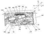
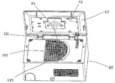
- FIG. 1 is a perspective view schematically showing an air treatment device according to an embodiment of the present invention, showing a state in which a lid body is opened with respect to a main body.
- FIG. 2 is a cross-sectional perspective view schematically showing the air treatment device according to the embodiment of the present invention.
- FIG. 3 is an exploded perspective view schematically showing the main body portion of the air treatment device according to the embodiment of the present invention.
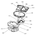
- FIG. 4 is an exploded perspective view schematically showing a part of the main body of the air treatment device according to the embodiment of the present invention.
- FIG. 1 is a perspective view schematically showing an air treatment device according to an embodiment of the present invention, showing a state in which a lid body is opened with respect to a main body.
- FIG. 3 is an exploded perspective view schematically showing the main body portion of the air treatment device according to the embodiment of the present invention.
- FIG. 4 is an exploded perspective view schematically showing a part of the main body of the air treatment device according to the embodiment of the present invention.
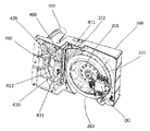
- FIG. 5 is a perspective view schematically showing a part of the main body of the air treatment device according to the embodiment of the present invention.
- FIG. 6 is an exploded perspective view schematically showing the humidity control rotor of the air treatment device according to the embodiment of the present invention.
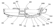
- FIG. 7 is a partial cross-sectional perspective view schematically showing the structure near the seal ring of the air treatment device according to the embodiment of the present invention.
- FIG. 8 is a partial cross-sectional perspective view schematically showing the structure near the seal ring of the air treatment device according to the embodiment of the present invention.
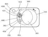
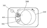
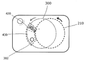
- FIG. 9 is a plan view schematically showing the movement of the fan rotor and the humidity control rotor of the air treatment device according to the embodiment of the present invention.
- FIG. 10 is a thermograph showing the temperature of each part during the operation of the air treatment device according to the embodiment of the present invention.
- FIG. 11 is a thermograph showing the temperature of each part during the operation of the air treatment device according to the comparative example.
- the air treatment device 1 includes a lid body GT and a body BT, the lid body GT and the body BT are pivotally connected, and the lid body GT can be opened and closed with respect to the body BT. Further, as shown in FIG.
- a gap is formed between the lid GT and the main body BT to allow air flow ( In the example shown, the airflow can enter the gap between the lid GT and the body BT from the surroundings).
- the main body has a suction port 101 and a first outlet 611, and the fan assembly 200, the humidity control rotor 300, and the heating assembly 400 are provided in the main body BT. It is provided.
- the fan assembly 200 has an air inlet 201 and a first air outlet 202.
- the humidity control rotor 300 has a rotation axis L2 that is substantially parallel to the rotation axis L1 of the fan rotor 210 of the fan assembly 200. Further, the humidity control rotor 300 has a moisture absorption area 301 and a moisture release area 302 that are adjacent to each other in the circumferential direction around the rotation axis L2 of the humidity control rotor 300. Further, as shown in FIG.
- the heating assembly 400 has a heating unit 420.
- the heating unit 420 heats at least a portion of the moisture release area 302 on the upstream side in the rotation direction of the humidity control rotor 300.
- the first air supply port 202 blows air to at least a portion of the moisture release area 302 on the upstream side in the rotation direction of the humidity control rotor 300.
- the rotation direction of the fan rotor 210 is the same as the rotation direction of the humidity control rotor 300.
- the main body BT includes, in addition to the suction port 101 (provided on the surface of the main body BT facing the lid GT) and the first outlet port 611, the second outlet port 102. (Depending on the situation, other air outlets may be further provided in addition to the first air outlet 611 and the second air outlet 102).
- the fan assembly 200 further includes a second air supply port 203 in addition to the air intake port 201 and the first air supply port 202. Further, as shown in FIG. 2, when the fan assembly 200 operates, the airflow enters from the outside, passes through the gap between the lid GT and the main body BT, and is sucked into the main body BT from the suction port 101.
- the airflow sucked into the main body BT from the suction port 101 passes through the moisture absorption area 301, enters the intake port 201 of the fan assembly 200, and then is divided into two paths.
- One is a path that is blown out from the first air outlet 202, passes through the moisture releasing area 302, and is discharged from the first outlet 611 (see arrow A1), and the other is the second air outlet. It is a path through which the second air outlet 102 is blown out from the mouth 203 and discharged (see arrow A2).
- the “moisture absorption area” is, by design, an area in which an airflow that tries to reach the intake port 201 of the fan assembly 200 from the suction port 101 flows (in the example shown in the figure, the central angle is larger than 180 °).
- the “moisture releasing area” refers to an area (shown in the drawing) where the air flow from the first air outlet 202 to the first outlet 611 flows. In the example, it is a fan shape having a central angle smaller than 180 °, but is not limited thereto.
- a portion of the moisture releasing area 302 that is closer to the upstream side in the rotation direction of the humidity control rotor 300 means a portion of the moisture releasing area 302 on the upstream side of the angle bisector (in the example shown in the drawing, a fan shape). It is a portion of the moisture releasing area 302 which is located upstream of the angle bisector).
- the first air supply port 202 blows air to at least a portion of the moisture release area 302 that is closer to the upstream side in the rotation direction of the humidity control rotor 300” is limited to blowing only to the upstream side portion. Instead of this, for example, the air may be blown to two-thirds of the entire moisture release area, which is closer to the upstream side.
- the casing 100 has a substantially rectangular parallelepiped shape, and has a front surface 110, a back surface 120, and a side surface 130.
- the front surface 110 faces the lid GT when the lid GT is closed with respect to the main body BT.
- the rear surface 120 (which is not limited to a flat surface and may have an irregular shape) faces the front surface 110.
- the side surface 130 is located between the front surface 110 and the back surface 120 and connects the front surface 110 and the back surface 120.
- a suction port 101 is provided in the front surface 110 of the casing 100 (specifically, it is provided substantially in the center of the front surface 110, but is not limited thereto. Not, it may be provided in other positions).
- a first filter LV1 is provided at the location of the suction port 101.
- the second outlet 102 is provided on the side surface 130 of the casing 100 (specifically, it is provided on one of the four side surfaces 130, which is closer to the Y1 direction, and is provided on the side of the side surface in the X2 direction). However, the present invention is not limited to this and may be provided at other positions).
- a second filter LV2 is provided at the location of the second outlet 102.
- the second outlet 102 of the casing 100 is directed downward in the vertical direction, so that another installation method (for example, the second outlet is upward or sideward). Dust is more difficult to enter the second outlet 102, and the normal operation of the air treatment device 1 for a long time can be surely performed.
- the casing 100 is provided with a partition portion 610 (specifically, the front surface 110 and the rear surface 120 are arranged so as to be perpendicular to the rotation axis L2 of the humidity control rotor 300). Between, but not limited to).
- the partition section 610 has a first outlet 611 and is provided so as to be adjacent to the humidity control rotor 300 in the radial direction of the humidity control rotor 300 (specifically, the partition section 610 is closer to the X1 direction, In addition, it is provided near the corner on the Y2 direction side, but is not limited to this, and it may be provided at a position where the air flow passing through the moisture release area can flow in and can communicate with the external air flow. However, it may be provided in other positions).
- the suction port 101 has a substantially semicircular shape as a whole (specifically, the shape is slightly larger than the semicircle, but the shape is not limited to this and may be another shape).
- the first outlet 611 exhibits a substantially circular shape as a whole (not limited to this, it may have another shape), and the second outlet 102 exhibits a substantially rectangular shape as a whole (not limited to this, Other shapes may be used).
- the exhaust duct 500 is connected to the first outlet 611 (specifically, from the first outlet 611 along the rotation axis L2 direction of the humidity control rotor 300). It extends toward the rear surface 120 side of the casing 100, but is not limited to this and may extend in other directions).
- the exhaust duct 500 is used to discharge the airflow blown from the first outlet 611 to the outside of the air conditioning target space.
- an electrical equipment box DH is provided inside the main body BT.
- the electrical component box DH is provided between the fan assembly 200 and the back surface 120, and the electrical component box DH is, when viewed along a direction (Y direction in the drawing) perpendicular to the rotation axis L1 of the fan rotor 210, It exhibits a trapezoid (specifically, a trapezoid in which the lower bottom is closer to the X2 direction side than the upper bottom).
- a shield plate 612 is provided between the first outlet 611 and the humidity control rotor 300 (specifically, an arc shape extending along the first outlet 611). However, the present invention is not limited to this and may be provided in other shapes).
- the shielding plate 612 prevents the airflow blown from the first air supply port 202 from passing through the moisture releasing area 302 and directly flowing to the first blowout port 611.
- the fan assembly 200 includes a fan rotor 210 provided inside the casing 100, and a scroll casing 220 that houses the fan rotor 210.
- the fan assembly 200 is, for example, a turbo fan.
- the fan rotor 210 is provided at a position close to the back surface 120 of the casing 100 so that its rotation axis L1 is not perpendicular to the front surface of the casing 100 (that is, tilted with respect to the front surface of the casing 100). Further, the fan rotor 210 has a blade portion 211.
- the scroll casing 220 independently constitutes the intake port 201, the first air supply port 202, and the second air supply port 203 (however, it is not limited to this, and One or more of the mouth 201, the first air supply port 202, and the second air supply port 203 may be configured by the scroll casing 220 and other members).
- the intake port 201 is oriented in the substantially Z1 direction
- the first air supply port 202 is oriented in the substantially X1 direction
- the second air supply port 203 is oriented in the substantially Y1 direction.
- the airflow blown out from the first air supply port 202 easily flows into the moisture release area 302 of the humidity control rotor 300, and the moisture release efficiency of the moisture release area 302 is increased. Is easy to improve.
- the second air supply port 203 by directing the second air supply port 203 in the substantially Y1 direction, the air flow blown out from the second air supply port 203 is delivered from the second air outlet 102 of the casing 100 to the air-conditioned space in a relatively short distance. Therefore, it is easy to improve the air blowing efficiency (of course, the directions of the air inlet 201, the first air outlet 202, and the second air outlet 203 are not limited to this, and the air flow can be branched. Any direction is fine).
- the first air supply port 202 corresponds to at least an upstream side portion in the rotational direction of the humidity control rotor 300 when viewed from the rotation axis L1 direction of the fan rotor 210 (specifically, corresponds only to a downstream side portion). If not, it may correspond to only the upstream side portion, or may correspond to the upstream side portion and the downstream side portion).
- the humidity control rotor 300 has a moisture absorption area 301 and a moisture release area 302 that are provided in the casing 100 and are adjacent to each other in the circumferential direction around the rotation axis L2 of the humidity control rotor 300.
- the humidity control rotor 300 is provided at a position close to the front surface 110 of the casing 100 so that the rotation axis L2 thereof is not perpendicular to the front surface of the casing 100 (that is, inclined with respect to the front surface of the casing 100).
- the rotation axis L2 of the humidity control rotor 300 is parallel to the rotation axis L1 of the fan rotor 210 but does not match, and the rotation axis L2 of the humidity control rotor 300 is greater than the rotation axis L1 of the fan rotor 210. It is closer to the X1 direction side (that is, closer to the heating assembly 400).
- the moisture absorption area 301 of the humidity control rotor 300 substantially corresponds to the suction port 101 of the casing 100, and the moisture absorption area 301 and the suction port 101 correspond to the rotation axis L2 of the humidity control rotor 300. Overlapping in the direction (the moisture absorption area 301 may be provided so as not to be parallel to the suction port 101 or to be parallel to the suction port 101, and the suction port 101 may even cover the moisture absorption area 301 substantially. Good).
- the moisture release area 302 of the humidity control rotor 300 and the suction port 101 of the casing 100 do not overlap in the rotation axis L2 direction of the humidity control rotor 300.
- the moisture absorption area 301 of the humidity control rotor 300 substantially corresponds to the intake port 201 of the fan assembly 200, and the moisture absorption area 301 and the intake port 201 are in the rotation axis L2 direction of the humidity control rotor 300.
- the humidity control rotor 300 may at least partially cover the intake port 201).
- the humidity control rotor 300 is rotated by the drive assembly QD attached to the scroll casing 220 of the fan assembly 200 (the humidity control rotor 300 may be directly driven by the drive assembly QD). However, it may be driven by the drive assembly QD via another member).
- the heating assembly 400 is provided within the casing 100. Specifically, the heating assembly 400 is provided in the path of the air flow that is blown out from the first air supply port 202 and passes through the moisture release area 302, and is located between the first air outlet 611 and the fan assembly 200. .
- the heating assembly 400 is adjacent to the fan assembly 200 in the radial direction of the fan assembly 200, and is adjacent to the humidity control rotor 300 in the rotation axis direction of the humidity control rotor 300.
- Humidification rotor 300 at least partially covers heating assembly 400 and fan assembly 200.
- the heating assembly 400 includes a heating assembly housing 410, and the heating assembly housing 410 has a heating assembly suction port 411 and a heating assembly outlet port 412.
- the heating assembly suction port 411 corresponds to the first air supply port 202 (specifically, but is not limited to, facing in the direction perpendicular to the rotation axis L1 of the fan rotor 210), and the size of the opening thereof. Is equal to or larger than the heating unit 420.
- the heating assembly outlet 412 corresponds to the moisture release area 302 (specifically, it is opposed to the direction of the rotation axis L2 of the humidity control rotor 300, but is not limited thereto).
- a heating part 420 and a buffer part 430 are provided in the heating assembly housing 410.
- the heating unit 420 at least partially corresponds to a portion of the moisture releasing area 302 on the upstream side in the rotation direction of the humidity control rotor 300 (in the example shown in the drawing, the heating unit 420 is included in the moisture releasing area 302). Since it corresponds to only the portion of the humidity control rotor 300 on the upstream side in the rotation direction, only the portion of the moisture release area 302 on the upstream side in the rotation direction of the humidity control rotor 300 is heated, but is not limited to this. For example, as shown in FIG. 12, the heating unit 420 may heat two-thirds of the entire moisture release area 302).
- the heating section 420 is configured by a heating wire provided corresponding to the heating assembly suction port 411 (may be configured by another heating member).
- the buffer section 430 partially corresponds to at least a portion of the moisture release area 302 on the downstream side in the rotation direction of the humidity control rotor 300 (in the example shown in the figure, the buffer section 430 is included in the moisture release area 302). Although it corresponds to only the portion of the humidity control rotor 300 on the downstream side in the rotation direction, the present invention is not limited to this. For example, as shown in FIG. 13, the buffer portion 430 corresponds to two-thirds of the entire moisture release area 302. May be). Further, the buffer section 430 is located closer to the downstream side than the heating section 420 in the rotation direction of the humidity control rotor 300.
- the buffer unit 430 includes a safety protection device 431 for ensuring safe operation of the air treatment device (for example, the temperature of the ambient air is detected, and when the ambient temperature is too high, the heating unit or the air is used).
- a safety protection device for stopping the operation of the processing device is provided.
- FIGS. 2 to 4 and 6 to 8 an upper frame 600 and a lower tray 700 are provided in the casing 100, and the upper frame 600 and the lower tray 700 rotate the humidity control rotor 300.
- the humidity control rotor 300 is sandwiched from both sides in the axis L2 direction.
- the upper frame 600 and the lower tray 700 are respectively formed with an upper frame side air flow path TD1 and a lower tray side air flow path TD2 corresponding to the moisture release area 302.
- the airflow blown out from the first air supply port 202 sequentially passes through the lower tray side air flow path TD2, the moisture release area 302, and the upper frame side air flow path TD1 to obtain the first blowing air. It is discharged from the outlet 611.
- the upper frame 600 has a partition portion 610 and a support portion 620 (that is, the upper frame 600 is integrally formed with the partition portion 610, but is not limited thereto. ).
- the partition part 610 and the support part 620 are adjacent to each other in the radial direction of the humidity control rotor 300, and the partition part 610 is located outside the support part 620 in the radial direction of the humidity control rotor 300.
- the support portion 620 has a bearing portion 621 and an air flow passage forming portion 622.
- the bearing portion 621 is inserted into the through hole 309 at the center of the humidity control rotor 300 and rotatably supports the humidity control rotor 300 (specifically, the bearing portion 621 is brought into contact with and engaged with the bearing portion 710 of the lower tray 700, Wet rotor 300 is rotatably supported).
- the air flow passage formation part 622 forms the upper frame side air flow passage TD1.
- the air flow path forming portion 622 surrounds the moisture release area 302 of the humidity control rotor 300 from the periphery when viewed along the rotation axis L2 direction of the humidity control rotor 300.
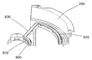
- a seal ring 800 is provided between the surface of the humidity control rotor 300 on the side opposite to the upper frame 600 side and the lower tray 700 so as to correspond to the moisture release area 302. It is provided in.
- a biasing unit 900 is provided on at least one of the lower tray 700 and the seal ring 800 (in the example shown in the figure, a part of the biasing unit 900 is provided on both the lower tray 700 and the seal ring 800. Have been).
- the biasing unit 900 applies an acting force to the seal ring 800 along the rotation axis L2 of the humidity control rotor 300 toward the humidity control rotor 300.
- the lower tray 700 is fixed to the scroll casing 220 of the fan rotor 210, and has a bearing portion 710 and an air flow passage forming portion 720.
- the bearing portion 710 and the air flow passage formation portion 720 are adjacent to each other in the radial direction of the humidity control rotor 300 with the rotation axis L2 as a reference, and the air flow passage formation portion 720 is more humid than the bearing portion 710. It is located on the radially outer side of 300.
- the bearing portion 710 is inserted into the through hole 309 in the center of the humidity control rotor 300 and rotatably supports the humidity control rotor 300 (specifically, abuts and engages with the bearing portion 621 of the upper frame 600.
- the air flow path forming unit 720 forms the lower tray side air flow path TD2.
- the air flow path forming unit 720 surrounds the moisture release area 302 of the humidity control rotor 300 from the periphery when viewed along the rotation axis L2 direction of the humidity control rotor 300.
- the air flow path forming unit 720 has a lower tray inner peripheral portion 721, a lower tray outer peripheral portion 722, and a lower tray intermediate portion 723.
- the inner peripheral portion 721 of the lower tray is connected to the bearing portion 710.
- the lower tray outer peripheral portion 722 has a first portion 7221 and a second portion 7222.
- the first portion 7221 faces the outer peripheral edge portion of the axial end surface of the humidity control rotor 300 with respect to the rotation axis L2.
- the second portion 7222 extends along the rotation axis L2 of the humidity control rotor 300 from the radially outer end of the first portion 7221 with respect to the rotation axis L2, and faces the outer peripheral surface of the humidity control rotor 300.
- the lower tray middle portion 723 forms a ring shape by connecting the lower tray inner peripheral portion 721 and the lower tray outer peripheral portion 722.
- the area of the portion surrounded by the ring shape substantially corresponds to the size of the moisture release area 302 of the humidity control rotor 300.
- the seal ring 800 has a ring shape corresponding to the ring shape formed by the lower tray inner peripheral portion 721, the lower tray outer peripheral portion 722, and the lower tray intermediate portion 723. It has an inner peripheral portion 810, a seal ring outer peripheral portion 820, and a seal ring intermediate portion 830 connecting the seal ring inner peripheral portion 810 and the seal ring outer peripheral portion 820.
- the urging unit 900 includes a pair magnet that applies a repulsive force of the magnet as an acting force, one of the pair magnets is provided in the lower tray 700, and the other is provided in the seal ring 800.
- the biasing unit 900 includes a plurality of pairs of magnets that apply a repulsive force of the magnets as an acting force, and the plurality of pairs of magnets are evenly arranged along the circumferential direction of the seal ring 800.
- a lower tray-side groove 701 for housing the seal ring 800 is provided on the surface of the lower tray 700 facing the seal ring 800, and the lower tray 700 of the seal ring 800 is provided.
- a seal ring side recessed groove 801 is provided on the surface facing to.
- a part of the biasing unit 900 (specifically, the other of the pair of magnets) is housed in the seal ring side concave groove 801.
- a friction prevention layer 1000 for contacting the humidity control rotor 300 is provided on the surface of the seal ring 800 facing the humidity control rotor 300.
- the fan assembly 200 has the intake port 201 and the first air supply port 202, and passes through the moisture absorption area 301 of the humidity control rotor 300 during operation of the fan assembly 200. A part of the airflow entering the intake port 201 is blown out from the first air outlet 202, passes through the moisture releasing area 302, and is then released from the first outlet 611.
- the air flow blown out from the first air blow port 202 of the fan assembly 200 is used to remove the moisture in the moisture release area 302 of the humidity control rotor 300. Since the moisture releasing effect can be enhanced, it contributes to simplification of the overall structure of the device.
- the heating section 420 of the heating assembly 400 heats at least the portion of the moisture release area 302 on the upstream side in the rotation direction of the humidity control rotor 300, so the moisture release area 302.
- the moisture release area 302. As shown in FIG. 10 and FIG. 11, it is easier to increase the area of the moisture releasing area that actually functions, as compared with the case where only the portion of the humidity controlling rotor 300 on the downstream side in the rotation direction is heated. This contributes to the improvement of the moisture releasing effect of the 300 moisture releasing areas. As a result, the dehumidification efficiency of the humidity control rotor 300 increases.
- the heating unit of the heating assembly 400 heats at least the portion of the moisture release area 302 on the upstream side in the rotation direction of the humidity control rotor 300, and the first air supply port 202. Blows air to at least a portion of the moisture release area 302 on the upstream side in the rotation direction of the humidity control rotor 300.
- the rotation direction of the fan rotor 210 is the same as the rotation direction of the humidity control rotor 300.
- the air flow blown from the first air supply port 202 of the fan assembly 200 is spread over the entire moisture release area 302 as compared with the case where the rotation direction of the fan rotor 210 and the rotation direction of the humidity control rotor 300 are different. This facilitates the improvement of the moisture releasing effect of the moisture releasing area 302 of the humidity control rotor 300.
- the dehumidification efficiency of the humidity control rotor 300 increases.
- the air treatment device 1 includes the lid GT and the main body BT, but is not limited to this, and the lid may be omitted depending on the situation.
- the partition portion 610 located between the front surface 110 and the back surface 120 of the casing 100 has the first outlet 611, but the invention is not limited to this.
- the first outlet 611 may be provided on the side surface 130 of the casing 100 or may be provided on the back surface 120 of the casing 100.
- the fan rotor 210 is provided inside the casing 100 so that the rotation axis L1 and the front surface of the casing 100 are not vertical
- the humidity control rotor 300 includes the rotation axis L2 and the casing 100. It is provided at a position close to the front surface 110 of the casing 100 so that the front surface of the casing is not vertical.
- the fan rotor 210 and the humidity control rotor 300 may be provided in the casing 100 such that their rotation axes L1 and L2 are perpendicular to the front surface of the casing 100.
- the first air supply port 202 of the fan assembly 200 blows air only to the portion of the moisture discharge area 302 that is closer to the upstream side in the rotation direction of the humidity control rotor 300, but is not limited to this. .
- the first air supply port 202 of the fan assembly 200 is a portion of the moisture releasing area 302 that is closer to the upstream side in the rotation direction of the humidity control rotor 300, and a portion that is closer to the upstream side in the lower rotation direction of the humidity control rotor 300. The air may be blown at the same time.
- the heating assembly 400 is provided in the path of the air flow that is blown out from the first air supply port 202 and passes through the moisture release area 302, but the present invention is not limited to this, and the heating assembly 400 is not limited thereto.
- the installation position may be appropriately adjusted depending on the situation.
- the heating assembly 400 heats only the portion of the moisture discharge area 302 that is closer to the upstream side in the rotation direction of the humidity control rotor 300, but is not limited to this.
- the heating assembly 400 may simultaneously heat a portion of the moisture release area 302 that is closer to the upstream side in the rotation direction of the humidity control rotor 300 and a portion of the more closer to the downstream side in the rotation direction downstream of the humidity control rotor 300 that is closer to the upstream side. .
- a sensor CG a temperature sensor, a humidity sensor, etc.
- the second position P2 of the lid GT which is separated from the moisture releasing area (eg, the lid GT, which is farther from the moisture releasing area than the suction port 101).
- a sensor a temperature sensor, a humidity sensor, etc. may be provided in a different place.
- the urging unit 900 includes the paired magnet that applies the repulsive force of the magnet as the acting force, but the present invention is not limited to this.
- the urging unit 900 may include an elastic member that applies an elastic force as an acting force.
- the lower tray 700 and the seal ring 800 is provided with a column 702 extending toward the other (in the example shown in the figure, the column 702 is provided on the lower tray 700).
- the biasing unit 900 includes a spring as an elastic member, and this spring is fitted in the column 702 and is housed in the seal ring side concave groove 801.
- the springs as elastic members are evenly arranged along the circumferential direction of the seal ring 800. Further, at least one of the lower tray 700 and the seal ring 800 is preferably provided with a position limiting hole (not shown) for accommodating the end portion of the spring. By doing so, the position and shape of the spring are more easily maintained (keeping the spring from twisting), so that the spring functions normally.
- the urging unit 900 may include both a pair magnet that applies a repulsive force of the magnet as an acting force and an elastic member that applies an elastic force as an acting force.
- the biasing unit 900 preferably includes a plurality of pairs of magnets and a plurality of elastic members.
- the plurality of pairs of magnets are evenly arranged along the circumferential direction of the seal ring 800 and the plurality of elastic members are evenly arranged along the circumferential direction of the seal ring 800.
- the magnets and the elastic members are provided alternately along the circumferential direction of the seal ring 800.
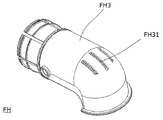
- a protection device FH which is connected directly or via the exhaust duct 500, as shown in FIGS. 16 and 17, may be further provided at the location of the first outlet 611.
- the protective device FH includes a backflow prevention damper FH1 and an insect net FH2.
- the protective device FH includes a mounting pipe FH3 connected to the first outlet 611 or the exhaust duct 500, a backflow prevention damper FH1 provided in the mounting pipe FH3, and Insect repellent net FH2 is included.
- a curved pipe portion for blocking rainwater is provided at an end portion of the mounting pipe FH3 (an end portion on the opposite side of the first outlet 611), and an exhaust groove FH31 is provided.
- Air Treatment Device 100 Casing 101 Inlet 102 Second Outlet 110 Front 120 Back 130 Side 200 Fan Assembly 201 Intake 202 First Air Outlet 203 Second Air Outlet 210 Fan Rotor 211 Blades 220 Scroll Casing 300 Humidity Control Rotor 301 Moisture absorbing area 302 Moisture releasing area 309 Through hole 400 Heating assembly 410 Heating assembly housing 411 Heating assembly inlet 412 Heating assembly outlet 420 Heating part 421 Heating wire 430 Buffer part 431 Safety protection device 500 Exhaust duct 600 Upper frame 610 Partition part 611 First outlet 612 Shielding plate 620 Supporting part 621 Bearing part 622 Air flow path forming part 700 Lower tray 701 Lower tray Side concave groove 702 Column 710 Bearing portion 720 Air flow path forming portion 721 Lower tray inner peripheral portion 722 Lower tray outer peripheral portion 723 Lower tray middle portion 7221 First portion 7222 Second portion 800 Seal ring 801 Seal ring Side concave groove 810 Seal ring Inner peripheral part 820 Seal ring Outer peripheral part 830 Seal ring middle part 900 Energi
Landscapes
- Engineering & Computer Science (AREA)
- Chemical & Material Sciences (AREA)
- Combustion & Propulsion (AREA)
- Mechanical Engineering (AREA)
- General Engineering & Computer Science (AREA)
- Analytical Chemistry (AREA)
- General Chemical & Material Sciences (AREA)
- Oil, Petroleum & Natural Gas (AREA)
- Chemical Kinetics & Catalysis (AREA)
- Drying Of Gases (AREA)
Abstract
ファンアセンブリ(200)の動作時、吸込口(101)から本体内に吸い込まれた空気流が、吸湿エリア(301)を通過して吸気口(201)に入った後、第1送気口(202)から吹き出され放湿エリア(302)を通過して第1吹出口(611)から放出される経路と、第2送気口(203)から第2吹出口(102)に吹き出されて放出される経路と、の2つの経路に分かれる。加熱アセンブリ(400)は加熱部(420)を有し、加熱部(420)は、少なくとも、放湿エリア(302)のうち調湿ロータ(300)の回転方向上流側寄りの部分を加熱する。第1送気口(202)は、少なくとも、放湿エリア(302)のうち調湿ロータ(300)の回転方向上流側寄りの部分に送風する。ファンロータ(210)及び調湿ロータ(300)の回転方向は同一である。当該構成により全体の構造が簡素化され、調湿ロータの放湿エリアの放湿効果と、除湿効果を高める。
Description
本発明は空気処理装置に関し、特に、空気の湿度を調節する機能を備えた空気処理装置に関する。
生活水準の向上に伴い、オフィス環境や居住環境に対する人々の要望もますます高まっている。例えば、冷房又は暖房用エアコン等の環境温度を調節する空気処理装置に対するニーズが拡大しているだけでなく、除湿機又は乾燥機等の環境湿度を調節する空気処理装置に対するニーズも同時に日増しに高まっている。
従来の除湿機の中には、圧縮機の冷媒を圧縮する特性を利用して除湿を行うものがあるが、このような除湿機は圧縮機を使用する必要があるため、製造コストが高い、運転音が大きい等の欠点がある。
このような従来の除湿機の欠点に対して、除湿ロータ式の除湿機が以前から提案されている。この除湿機では、例えばゼオライトを材料として用いて除湿ロータを製造する。そして、この除湿ロータの吸湿特性を利用することによって、圧縮機を使用することなく空気の湿度を調節する機能を実現することができる(例えば、特許文献1:中国実用新案第202096871号を参照)。
上述の除湿ロータ式除湿機では、常温で湿気を吸収でき、高温で湿気を放出できるという除湿ロータの特性を利用して、除湿ロータの吸湿後のエリアを加熱して再生させる電熱装置を設けることによって、長時間の除湿機能を容易に実現することができる。
しかし、上述の除湿ロータ式除湿機では、空気吸入装置内を除湿ロータで除湿して除湿後の空気を室内に送る送風ユニットに加え、除湿ロータの吸湿後のエリアの加熱再生効率向上のために、専用の送風装置を更に設けて、電熱装置に送風し、電熱装置を通って加熱された後の空気を利用して、除湿ロータの吸湿後のエリアを加熱する必要がある。このため、装置全体が複雑になり、製造コストの増大を招く。
本発明は、まさに上述の課題を解決するためになされたものであり、全体の構造を簡素化するとともに、調湿ロータの放湿エリアの放湿効果の向上に寄与し、除湿効果を高める空気処理装置を提供することを目的とする。
上述の目的を達成するために、本発明は、以下の空気処理装置を提供する。空気処理装置は、本体を有する。本体は、吸込口と、第1吹出口と、第2吹出口とを有する。本体内には、ファンアセンブリと、調湿ロータと、加熱アセンブリとが設けられている。ファンアセンブリは吸気口と、第1送気口と、第2送気口とを有する。調湿ロータは、ファンアセンブリのファンロータの回転軸に略平行な回転軸を有し、調湿ロータの回転軸を中心とする周方向において互いに隣接する、吸湿エリア及び放湿エリアを有する。ファンアセンブリの動作時、吸込口から本体内に吸い込まれた空気流は、吸湿エリアを通過してファンアセンブリの吸気口に入った後、2つの経路に分かれる。1つは、第1送気口から吹き出され、放湿エリアを通過して、第1吹出口から放出される経路であり、もう1つは、第2送気口から第2吹出口に吹き出されて放出される経路である。加熱アセンブリは、加熱部を有する。加熱部は、少なくとも、放湿エリアのうち調湿ロータの回転方向上流側寄りの部分を加熱する。第1送気口は、少なくとも、放湿エリアのうち調湿ロータの回転方向上流側寄りの部分に送風する。ファンロータの回転方向と調湿ロータの回転方向は同一である。
ここで、「調湿ロータは、ファンアセンブリのファンロータの回転軸に略平行な回転軸を有する」とは、調湿ロータの回転軸とファンアセンブリのファンロータの回転軸とが厳密に平行である場合に限定されず、製造や組立による誤差、又は動作時の振動や熱による変形等が原因で、調湿ロータの回転軸が、ファンアセンブリのファンロータの回転軸に対してわずかに傾いている場合も含まれる。
本発明の空気処理装置によると、ファンアセンブリは、吸気口及び第1送気口を有し、ファンアセンブリの動作時、調湿ロータの吸湿エリアを通過してファンアセンブリの吸気口に入った空気流の一部は、第1送気口から吹き出され放湿エリアを通過した後に、第1吹出口から放出される。これにより、専用の送風装置を設けて加熱アセンブリに送風する必要がなく、ファンアセンブリの第1送気口から吹き出された空気流を利用して、調湿ロータの放湿エリアの放湿効果を高めることができ、装置全体の構造の簡素化に寄与する。
また、本発明の空気処理装置によると、加熱アセンブリの加熱部は、少なくとも、放湿エリアのうち調湿ロータの回転方向上流側寄りの部分を加熱するので、放湿エリアのうち調湿ロータの回転方向下流側寄りの部分のみを加熱する場合と比べて、実際に機能する放湿エリアの面積を大きくしやすく、調湿ロータの放湿エリアの放湿効果の向上に寄与する。その結果、調湿ロータの除湿効率が上がる。
また、本発明の空気処理装置によると、加熱アセンブリの加熱部は、少なくとも、放湿エリアのうち調湿ロータの回転方向上流側寄りの部分を加熱し、第1送気口は、少なくとも、放湿エリアのうち調湿ロータの回転方向上流側寄りの部分に送風する。また、ファンロータの回転方向は、調湿ロータの回転方向と同一である。これにより、ファンロータの回転方向と調湿ロータの回転方向とが異なる場合に比べて、ファンアセンブリの第1送気口から吹き出された空気流が、放湿エリア全体に行き渡りやすく、放湿エリアの温度を更に均一にするので、調湿ロータの放湿エリアの放湿効果の向上に寄与する。その結果、調湿ロータの除湿効率が上がる。
また、本発明の空気処理装置において、以下の構成を更に採用することができる。加熱アセンブリは、緩衝部を更に有する。緩衝部は、少なくとも、放湿エリアのうち調湿ロータの回転方向下流側寄りの部分と、部分的に対応し、且つ、調湿ロータの回転方向において、加熱部よりも下流側にある。
上述の構成の空気処理装置によると、第1送気口が放湿エリアのうち調湿ロータの回転方向上流側寄りの部分に送風する場合、空気流が、放湿エリアのうち調湿ロータの回転方向下流側寄りの部分に到達しにくい恐れがある。このため、この下流側の部分を加熱部により加熱すると、この下流側部分付近の温度が上昇しすぎる現象が起こりやすく、安全上の潜在リスクが存在する。これに対し、調湿ロータの回転方向において加熱部よりも下流側の位置に、放湿エリアに対し加熱を行わない緩衝部を設けると、上述の安全上の潜在リスクを回避しやすい。更に、少なくとも、放湿エリアのうち調湿ロータの回転方向下流側寄りの部分と、部分的に対応する緩衝部を設けることによって、調湿ロータの放湿エリア部分の緩衝部通過後の温度をある程度下げることができる。これにより、調湿ロータの放湿エリア部分が熱を受けた後に過度に温度上昇することによって、放湿エリア部分が回転して吸湿エリアに到達した時の吸湿作用効率に影響を与えてしまうのを防ぐことができる。その結果、調湿ロータの放湿効率が高まる。
また、本発明の空気処理装置において、好ましくは、加熱アセンブリは、第1送気口から吹き出されて放湿エリアを通過する空気流の経路に、少なくとも部分的に設置される。
本発明の空気処理装置によると、第1送気口から吹き出された空気流は、加熱アセンブリにより加熱された後に、調湿ロータの放湿エリアを通過することができるので、調湿ロータの放湿エリアの放湿効果の更なる向上に寄与する。その結果、調湿ロータの除湿効率が上がる。
また、上述の構成の空気処理装置において、以下の構成を採用することができる。加熱アセンブリは、第1吹出口とファンアセンブリとの間に位置している。
上述の構成の空気処理装置によると、調湿ロータの除湿効率が向上するのと同時に、装置全体の小型化の実現に寄与する。
また、上述の構成の空気処理装置において、以下の構成を採用することもできる。加熱アセンブリは、加熱アセンブリハウジングを有する。加熱アセンブリハウジングは、加熱アセンブリ吸込口及び加熱アセンブリ吹出口を有する。加熱アセンブリ吸込口は、第1送気口と対応する。加熱アセンブリ吹出口は、放湿エリアと対応する。
上述の構成の空気処理装置によると、ファンアセンブリの第1送気口から吹き出された空気流が加熱アセンブリを通過しやすく、且つ加熱アセンブリの加熱アセンブリ吹出口から吹き出された空気流が放湿エリアを通過しやすい。従って、加熱アセンブリを通って加熱された後の空気流を利用して、調湿ロータの放湿エリアの放湿効果を更に容易に向上させることができる。その結果、調湿ロータの除湿効率が上がる。
また、上述の構成の空気処理装置において、以下の構成を更に採用することができる。加熱アセンブリ吸込口は、加熱部と対応して設置され、その開口の大きさは、加熱部と等しいか、又は加熱部よりも大きい。
上述の構成の空気処理装置によると、ファンアセンブリの第1送気口から吹き出された空気流が、加熱アセンブリの加熱部を更に通過しやすくなるので、加熱アセンブリを通って加熱された後の空気流を利用して、調湿ロータの放湿エリアの放湿効果を更に容易に向上させることができる。その結果、調湿ロータの除湿効率が上がる。
また、上述の構成の空気処理装置において、以下の構成を更に採用することができる。緩衝部は、空気処理装置の安全な運転を確実にするための安全保護装置を含む。
上述の構成の空気処理装置によると、空きスペースになりやすい緩衝部に、安全保護装置を配置することにより、装置の寸法を大きくすることなく、運転の安全性を向上させやすい。特に、周囲の温度が高すぎる時に、加熱部又は空気処理装置の動作を停止させる安全保護装置を緩衝部に設けると、容易に且つ効果的に、安全上の潜在リスクを検出することができるので、確実に空気処理装置を保護することができる。
また、上述の構成の空気処理装置において、以下の構成を採用することもできる。加熱アセンブリは、ファンアセンブリの径方向において、ファンアセンブリに隣接しており、且つ調湿ロータの回転軸方向において、調湿ロータに隣接している。また、調湿ロータは、加熱アセンブリ及びファンアセンブリを、少なくとも部分的に覆う。
上述の構成の空気処理装置によると、ファンアセンブリの第1送気口から吹き出された空気流が加熱アセンブリを通過しやすいので、加熱アセンブリを通って加熱された後の空気流を利用して、調湿ロータの放湿エリアの放湿効果を向上させやすい。その結果、調湿ロータの除湿効率が上がる。更に、調湿ロータ、加熱アセンブリ、及びファンアセンブリはコンパクトに配置されているので、装置全体の小型化を実現しやすい。
また、上述の構成の空気処理装置において、以下の構成を採用することができる。本体は、ケーシング及び仕切部を含む。ケーシングは、吸込口及び第2吹出口を有する。ファンアセンブリ、調湿ロータ、加熱アセンブリ、及び仕切部は、ケーシング内に設けられている。仕切部は、第1吹出口を有し、調湿ロータの径方向において、調湿ロータに隣接している。
また、上述の構成の空気処理装置において、以下の構成を採用することができる。仕切部には、第1吹出口と調湿ロータとの間に、遮蔽板が設けられている。
上述の構成の空気処理装置によると、第1送気口から吹き出された空気流が放湿エリア全体を通過しやすくなるので、実際に機能する放湿エリアの面積を大きくしやすく、調湿ロータの放湿エリアの放湿効果の向上に寄与する。その結果、調湿ロータの除湿効率が上がる。
また、本発明の空気処理装置では、第1吹出口に排気ダクトが接続されていることが好ましい。
上述の構成の空気処理装置によると、必要に応じて、第1吹出口から吹き出された空気流の方向を柔軟に設定することができる。
また、上述の構成の空気処理装置において、以下の構成を採用することができる。ファンアセンブリは、ファンロータを収容するスクロールケーシングを有する。吸気口、第1送気口、及び第2送気口のうち少なくとも1つは、スクロールケーシングのみによって構成されるか、或いは、ケーシング及びスクロールケーシングによって構成される。ファンアセンブリ、調湿ロータ、及び加熱アセンブリは、ケーシング内に設けられている。
上述の構成の空気処理装置によると、吸い込まれる空気量又は放出される空気量を精密に制御しやすく、吸気口、送気口を接合する時の隙間に起因する空気漏れ等を防ぐことができる。
また、上述の構成の空気処理装置において、以下の構成を更に採用することができる。本体は、前面と、背面と、側面とを有する。背面は、前面に対向する。側面は、前面と背面との間に位置する。吸込口は、前面に設けられる。第2吹出口は、側面に設けられる。
上述の構成の空気処理装置によると、吸込口と第2吹出口との間で、空気流のショートサーキットが起こるのを防ぎやすい。
また、本発明の空気処理装置において、好ましくは、蓋体(GT)を更に含む。蓋体と本体との間には隙間が形成されている。吸込口は、本体の、蓋体に面する面に設けられている。ファンアセンブリの動作時、空気流は外部から隙間を通って吸込口に入る。
上述の構成の空気処理装置によると、吸込口を蓋体で覆うことにより、外部の塵埃が吸込口に付着して吸気効率に影響を及ぼすことを防ぎやすい。また、装置全体の美観性の向上にも寄与する。
また、上述の構成の空気処理装置において、以下の構成を採用することができる。本体には、上フレーム及び下トレイが設けられている。上フレーム及び下トレイは、調湿ロータの回転軸方向両側から、調湿ロータを挟持する。上フレーム及び下トレイにはそれぞれ、放湿エリアと対応する、上フレーム側空気流路及び下トレイ側空気流路が形成されている。ファンアセンブリの動作時、第1送気口から吹き出された空気流は、下トレイ側空気流路、放湿エリア、及び上フレーム側空気流路を順に通過して、第1吹出口から放出される。調湿ロータの上フレーム側とは反対側の面と、下トレイとの間には、放湿エリアと対応するように、シールリングが設けられている。
本発明の空気処理装置によると、調湿ロータの回転軸方向両側には、放湿エリアと対応する下トレイ側空気流路及び上フレーム側空気流路をそれぞれ有する下トレイ及び上フレームが、調湿ロータを挟持するように設けられる。また、調湿ロータの上フレーム側とは反対側の面と下トレイとの間には、放湿エリアと対応するように、シールリングが設けられる。これにより、調湿ロータの回転が安定しやすくなる上、第1送気口から吹き出された空気流が、調湿ロータの放湿エリアに集中して流れやすい。また、調湿ロータの吸湿エリアを通る空気流と、調湿ロータの放湿エリアを通る空気流とが、互いに干渉し合うのを防ぎやすい。その結果、調湿ロータの除湿効率が上がる。
また、上述の構成の空気処理装置において、以下の構成を採用することもできる。下トレイには、又は下トレイ及びシールリングには、付勢ユニットが設けられており、付勢ユニットは、シールリングに対して、調湿ロータの回転軸に沿い調湿ロータに向かって、作用力を加える。
上述の構成の空気処理装置によると、調湿ロータの回転時にも、シールリングを調湿ロータに密着させやすく、第1送気口から吹き出された空気流を、より良好に調湿ロータの放湿エリアに向かわせることができる。これにより、調湿ロータの放湿エリアの放湿効果を向上させやすい。その結果、調湿ロータの除湿効率が上がる。
また、上述の構成の空気処理装置において、以下の構成を更に採用することができる。下トレイの、シールリングに対向する面には、シールリングを収容する下トレイ側凹溝が設けられている。
上述の構成の空気処理装置によると、調湿ロータの回転時に、シールリングが調湿ロータの回転による外力を受けて位置ずれを起こすことを防止しやすいので、シールリングのシール作用がより良好に発揮されやすい。
また、上述の構成の空気処理装置において、以下の構成を更に採用することができる。シールリングの、下トレイに面する面には、シールリング側凹溝が設けられており、付勢ユニットの少なくとも一部は、このシールリング側凹溝内に収容されている。
上述の構成の空気処理装置によると、調湿ロータの回転時に、付勢ユニットが外力を受けて位置ずれを起こすことを防止しやすいので、付勢ユニットの作用がより良好に発揮されやすい。
また、上述の構成の空気処理装置において、以下の構成を更に採用することができる。付勢ユニットは、作用力としての磁石の斥力を加える、1対又は複数対の磁石を含む、且つ/或いは、付勢ユニットは、作用力としての弾性力を加える、1つ又は複数の弾性部材を含む。
上述の構成の空気処理装置によると、簡単な構成で付勢ユニットを実現することができ、製造コストの低減に寄与する。
また、上述の構成の空気処理装置において、以下の構成を更に採用することができる。下トレイ及びシールリングの少なくとも一方には、他方に向かって延びる柱が設けられている。付勢ユニットは、作用力としての弾性力を加えるバネを含む。バネは、柱に嵌められて、シールリング側凹溝に収容される。
上述の構成の空気処理装置によると、調湿ロータの回転時に、バネが外力を受けることよって位置ずれ又は変形を起こすことを確実に防止しやすいので、バネの作用がより良好に発揮されやすい。
また、上述の構成の空気処理装置において、以下の構成を採用することもできる。シールリングの、調湿ロータに面する面には、調湿ロータが当接する摩擦防止層が設けられている。
上述の構成の空気処理装置によると、調湿ロータの回転時に、摩擦によって生じる転がり抵抗を低減しやすい。従って、駆動力の比較的小さい小型の駆動装置を使って調湿ロータを回転させることが容易であり、装置全体の小型化に寄与する。
また、上述の構成の空気処理装置において、以下の構成を更に採用することができる。本体は、前面と、背面と、側面とを有する。背面は、前面に対向する。側面は、前面と背面との間に位置する。ファンロータの回転軸は、前面に対して傾斜している。本体内には、電装品箱が設けられている。電装品箱は、ファンアセンブリと背面との間に設けられる。電装品箱は、ファンロータの回転軸に垂直な方向に沿って見た時に、台形を呈す。
上述の構成の空気処理装置によると、装置全体を小型化しやすい。
また、上述の構成の空気処理装置において、以下の構成を更に採用することができる。吸込口の、放湿エリアから離れた箇所に、センサが設けられている。
上述の構成の空気処理装置によると、センサの検出精度が、加熱アセンブリの発熱による影響を受けにくいだけでなく、加熱された調湿ロータによる発熱の影響も受けにくい。よって、センサの検出結果に応じて、高い精度で空気処理装置を制御しやすい。
また、上述の構成の空気処理装置において、以下の構成を更に採用することができる。本体に対向する蓋体を更に含む。蓋体の放湿エリアから離れた箇所にセンサが設けられている。
上述の構成の空気処理装置によると、センサの検出精度が、加熱アセンブリの発熱による影響を受けにくいだけでなく、加熱された調湿ロータによる発熱の影響も受けにくい。よって、センサの検出結果に応じて、高い精度で空気処理装置を制御しやすい。
また、上述の構成の空気処理装置において、以下の構成を更に採用することができる。第1吹出口には、防護装置が連結されている。防護装置は、逆流防止ダンパ及び/又は防虫ネットを含む。
上述の構成の空気処理装置によると、汚れた空気流、雨水又は飛来昆虫等が第1吹出口を通って空気処理装置の内部に入り、空気処理装置の正常な運転に影響を及ぼしてしまうことを防ぐことができる。
本発明によると、ファンアセンブリは、吸気口及び第1送気口を有し、ファンアセンブリの動作時、調湿ロータの吸湿エリアを通過してファンアセンブリの吸気口に入った空気流の一部は、第1送気口から吹き出され放湿エリアを通過した後に、第1吹出口から放出される。これにより、専用の送風装置を設けて加熱アセンブリに送風する必要がなく、ファンアセンブリの第1送気口から吹き出された空気流を利用して、調湿ロータの放湿エリアの放湿効果を高めることができ、装置全体の構造の簡素化に寄与する。
また、本発明によると、加熱アセンブリの加熱部は、少なくとも、放湿エリアのうち調湿ロータの回転方向上流側寄りの部分を加熱するので、放湿エリアのうち調湿ロータの回転方向下流側寄りの部分のみを加熱する場合と比べて、実際に機能する放湿エリアの面積を大きくしやすく、調湿ロータの放湿エリアの放湿効果の向上に寄与する。その結果、調湿ロータの除湿効率が上がる。
また、本発明によると、加熱アセンブリの加熱部は、少なくとも、放湿エリアのうち調湿ロータの回転方向上流側寄りの部分を加熱し、第1送気口は、放湿エリアのうち調湿ロータの回転方向上流側寄りの部分に送風する。また、ファンロータの回転方向は、調湿ロータの回転方向と同一である。これにより、ファンロータの回転方向と調湿ロータの回転方向とが異なる場合に比べて、ファンアセンブリの第1送気口から吹き出された空気流が、放湿エリア全体に行き渡りやすく、調湿ロータの放湿エリアの放湿効果の向上に寄与する。その結果、調湿ロータの除湿効率が上がる。
以下、図1~図11を参照しながら、本発明の実施形態に係る空気処理装置について説明する。図1は、本発明の実施形態に係る空気処理装置を模式的に示す斜視図であり、蓋体が本体に対して開いている状態を示す。図2は、本発明の実施形態に係る空気処理装置を模式的に示す断面斜視図である。図3は、本発明の実施形態に係る空気処理装置の本体部分を模式的に示す分解斜視図である。図4は、本発明の実施形態に係る空気処理装置の本体の一部を模式的に示す分解斜視図である。図5は、本発明の実施形態に係る空気処理装置の本体の一部を模式的に示す斜視図である。図6は、本発明の実施形態に係る空気処理装置の調湿ロータを模式的に示す分解斜視図である。図7は、本発明の実施形態に係る空気処理装置のシールリング付近の構造を模式的に示す部分的な断面斜視図である。図8は、本発明の実施形態に係る空気処理装置のシールリング付近の構造を模式的に示す部分的な断面斜視図である。図9は、本発明の実施形態に係る空気処理装置のファンロータ及び調湿ロータの運動について模式的に示す平面図である。図10は、本発明の実施形態に係る空気処理装置の動作時における各部分の温度を示すサーモグラフィーである。図11は、比較例に係る空気処理装置の動作時における各部分の温度を示すサーモグラフィーである。
ここで、説明の便宜上、互いに直交する3つの方向をX方向、Y方向、Z方向とする。X方向の一方をX1、X方向の他方をX2とし、Y方向の一方をY1、Y方向の他方をY2とし、Z方向の一方をZ1、Z方向の他方をZ2とする。
(全体構造)
図1に示すように、空気処理装置1は、蓋体GT及び本体BTを含み、蓋体GTと本体BTとはピボット連結され、蓋体GTは本体BTに対して開閉可能である。また、図2に示すように、蓋体GTが本体BTに対して閉じられた状態において、蓋体GTと本体BTとの間には、空気流が通ることのできる隙間が形成されている(図に示す例では、空気流は、周りから蓋体GTと本体BTとの間の隙間に入ることができる)。
(全体構造)
図1に示すように、空気処理装置1は、蓋体GT及び本体BTを含み、蓋体GTと本体BTとはピボット連結され、蓋体GTは本体BTに対して開閉可能である。また、図2に示すように、蓋体GTが本体BTに対して閉じられた状態において、蓋体GTと本体BTとの間には、空気流が通ることのできる隙間が形成されている(図に示す例では、空気流は、周りから蓋体GTと本体BTとの間の隙間に入ることができる)。
また、図1及び図2に示すように、本体は、吸込口101及び第1吹出口611を有し、本体BT内には、ファンアセンブリ200と、調湿ロータ300と、加熱アセンブリ400とが設けられている。ファンアセンブリ200は、吸気口201及び第1送気口202を有する。調湿ロータ300は、ファンアセンブリ200のファンロータ210の回転軸L1に略平行な回転軸L2を有する。また、調湿ロータ300は、調湿ロータ300の回転軸L2を中心とする周方向において互いに隣接する、吸湿エリア301及び放湿エリア302を有する。また、図2に示すように、ファンアセンブリ200の動作時、吸込口101から本体BT内に吸い込まれた空気流は、吸湿エリア301を通過してファンアセンブリ200の吸気口201に入る。その後、そのうちの少なくとも一部の空気流は、第1送気口202から吹き出され、放湿エリア302を通過して、第1吹出口611から放出される。また、図9に示すように、加熱アセンブリ400は、加熱部420を有する。加熱部420は、少なくとも、放湿エリア302のうち調湿ロータ300の回転方向上流側寄りの部分を加熱する。第1送気口202は、少なくとも、放湿エリア302のうち調湿ロータ300の回転方向上流側寄りの部分に送風する。ファンロータ210の回転方向は、調湿ロータ300の回転方向と同一である。
ここで、図1及び図2に示すように、本体BTは、吸込口101(本体BTの、蓋体GTに面する面に設けられる)及び第1吹出口611に加え、第2吹出口102を更に有する(状況に応じて、第1吹出口611及び第2吹出口102以外に、他の吹出口を更に設けてもよい)。また、図3に示すように、ファンアセンブリ200は、吸気口201及び第1送気口202に加え、第2送気口203を更に有する。また、図2に示すように、ファンアセンブリ200の動作時、空気流は、外部から入り、蓋体GTと本体BTとの間の隙間を通って、吸込口101から本体BT内に吸い込まれる。吸込口101から本体BT内に吸い込まれた空気流は、吸湿エリア301を通過して、ファンアセンブリ200の吸気口201に入った後、2つの経路に分かれる。1つは、第1送気口202から吹き出され、放湿エリア302を通過して、第1吹出口611から放出される経路であり(矢印A1参照)、もう1つは、第2送気口203から第2吹出口102に吹き出されて放出される経路である(矢印A2参照)。
なお、本願において、「吸湿エリア」とは、設計上、吸込口101からファンアセンブリ200の吸気口201に到達しようとする空気流が流れるエリア(図に示す例では中心角が180°よりも大きい扇形であるが、これに限定されない)を指し、「放湿エリア」とは、設計上、第1送気口202から第1吹出口611に到達しようとする空気流が流れるエリア(図に示す例では、中心角が180°よりも小さい扇形であるが、これに限定されない)を指す。また、「放湿エリア302のうち調湿ロータ300の回転方向上流側寄りの部分」とは、放湿エリア302の角二等分線よりも上流側の部分(図に示す例では、扇形の放湿エリア302の角二等分線よりも上流側の部分である)を指す。また、「第1送気口202は、少なくとも放湿エリア302のうち調湿ロータ300の回転方向上流側寄りの部分に送風する」とは、上流側の部分のみに送風することに限定されるのではなく、例えば、放湿エリア全体のうち上流側寄りである3分の2に送風してもよい。
(ケーシングの構造)
図1に示すように、ケーシング100は略直方体形状を呈し、前面110と、背面120と、側面130とを有する。前面110は、蓋体GTが本体BTに対して閉じられている時、蓋体GTに対向する。背面120は(平らな面に限定されず、不規則な形状であってもよい)、前面110に対向する。側面130は、前面110と背面120との間に位置して、前面110と背面120とを繋ぐ。
(ケーシングの構造)
図1に示すように、ケーシング100は略直方体形状を呈し、前面110と、背面120と、側面130とを有する。前面110は、蓋体GTが本体BTに対して閉じられている時、蓋体GTに対向する。背面120は(平らな面に限定されず、不規則な形状であってもよい)、前面110に対向する。側面130は、前面110と背面120との間に位置して、前面110と背面120とを繋ぐ。
ここで、図1及び図2に示すように、ケーシング100の前面110には、吸込口101が設けられている(具体的には、前面110のほぼ中央に設けられているが、これに限定されず、他の位置に設けられていてもよい)。この吸込口101の箇所には、第1フィルタLV1が設けられている。ケーシング100の側面130には、第2吹出口102が設けられている(具体的には、4つの側面130のうちY1方向寄りの側面に設けられ、且つこの側面のX2方向側の場所に設けられるが、これに限定されず、他の位置に設けられてもよい)。この第2吹出口102の箇所には、第2フィルタLV2が設けられている。実際の使用時(すなわち、縦方向に取り付けられる時)には、ケーシング100の第2吹出口102を縦方向下方に向けることによって、他の設置方法(例えば、第2吹出口を上方又は側方に向ける)よりも、塵埃が第2吹出口102に入りにくくなり、空気処理装置1の長時間にわたる正常動作が確実に行われやすい。また、図2に示すように、ケーシング100には、仕切部610が設けられている(具体的には、調湿ロータ300の回転軸L2と垂直になるように、前面110と背面120との間に設けられているが、これに限定されない)。仕切部610は、第1吹出口611を有し、調湿ロータ300の径方向において、調湿ロータ300に隣接するように設けられている(具体的には、仕切部610のX1方向寄り、且つY2方向側の角部付近に設けられるが、これに限定されず、放湿エリアを通過する空気流が流入可能な位置であって、外部の空気流と連通可能な位置に設けられていれば、他の位置に設けられてもよい)。また、吸込口101は、全体として略半円形を呈する(具体的には、半円よりもわずかに大きい形状であるが、これに限定されず、他の形状であってもよい)。第1吹出口611は、全体として略円形を呈し(これに限定されず、他の形状であってもよい)、第2吹出口102は、全体として略矩形を呈する(これに限定されず、他の形状であってもよい)。
また、図2に示すように、第1吹出口611には、排気ダクト500が接続されている(具体的には、調湿ロータ300の回転軸L2方向に沿って、第1吹出口611からケーシング100の背面120側に向かって延びているが、これに限定されず、他の方向に向かって延びていてもよい)。この排気ダクト500は、第1吹出口611から吹き出された空気流を空調対象空間の外に排出するために用いられる。
また、図2に示すように、本体BT内には、電装品箱DHが設けられている。電装品箱DHは、ファンアセンブリ200と背面120との間に設けられ、電装品箱DHは、ファンロータ210の回転軸L1に垂直な方向(図中のY方向)に沿って見た時に、台形(具体的には、下底が上底よりもX2方向側寄りにある台形)を呈する。
また、図9に示すように、第1吹出口611と調湿ロータ300との間には、遮蔽板612が設けられている(具体的には、第1吹出口611に沿って延びる円弧状を呈しているが、これに限定されず、他の形状になるように設けられてもよい)。この遮蔽板612は、第1送気口202から吹き出された空気流が、放湿エリア302を通って、直接第1吹出口611に流れることを防止する。
(ファンアセンブリの構造)
図2、図4、及び図5に示すように、ファンアセンブリ200は、ケーシング100内に設けられ、ファンロータ210と、ファンロータ210を収容するスクロールケーシング220とを有する。
(ファンアセンブリの構造)
図2、図4、及び図5に示すように、ファンアセンブリ200は、ケーシング100内に設けられ、ファンロータ210と、ファンロータ210を収容するスクロールケーシング220とを有する。
ここで、ファンアセンブリ200は、例えばターボファンである。ファンロータ210は、その回転軸L1がケーシング100の前面と垂直にならないように(すなわち、ケーシング100の前面に対して傾斜するように)、ケーシング100の背面120に近い位置に設けられる。また、ファンロータ210は羽根部211を有する。
また、図4及び図5に示すように、スクロールケーシング220は単独で、吸気口201、第1送気口202、及び第2送気口203を構成する(ただし、これに限定されず、吸気口201、第1送気口202、及び第2送気口203のうち1つ又は複数は、スクロールケーシング220及び他の部材によって構成されてもよい)。また、吸気口201は略Z1方向に向いており、第1送気口202は略X1方向に向いており、第2送気口203は略Y1方向に向いている。第1送気口202を略X1方向に向けることで、第1送気口202から吹き出された空気流が、調湿ロータ300の放湿エリア302に流れやすく、放湿エリア302の放湿効率が向上しやすい。一方、第2送気口203を略Y1方向に向けることで、第2送気口203から吹き出された空気流を、ケーシング100の第2吹出口102から空調対象空間に比較的短い距離で届けることができるため、送風効率を向上させやすい(当然ながら、吸気口201、第1送気口202、及び第2送気口203の向きはこれに限定されず、空気流を分岐させることができる方向であればよい)。
また、第1送気口202は、ファンロータ210の回転軸L1方向から見た時に、少なくとも調湿ロータ300の回転方向上流側部分と対応する(具体的には、下流側部分のみと対応するのでなければよく、上流側部分のみと対応してもよいし、上流側部分及び下流側部分と対応してもよい)。
(調湿ロータの構造)
図2に示すように、調湿ロータ300は、ケーシング100内に設けられ、調湿ロータ300の回転軸L2を中心とする周方向において互いに隣接する、吸湿エリア301及び放湿エリア302を有する。
(調湿ロータの構造)
図2に示すように、調湿ロータ300は、ケーシング100内に設けられ、調湿ロータ300の回転軸L2を中心とする周方向において互いに隣接する、吸湿エリア301及び放湿エリア302を有する。
ここで、調湿ロータ300は、その回転軸L2がケーシング100の前面と垂直にならないように(すなわち、ケーシング100の前面に対して傾斜するように)、ケーシング100の前面110に近い位置に設けられる。また、調湿ロータ300の回転軸L2は、ファンロータ210の回転軸L1と平行であるが一致はしておらず、調湿ロータ300の回転軸L2は、ファンロータ210の回転軸L1よりもX1方向側寄りである(すなわち、加熱アセンブリ400に近い)。
また、図2に示すように、調湿ロータ300の吸湿エリア301は、ケーシング100の吸込口101とほぼ対応しており、吸湿エリア301と吸込口101とは、調湿ロータ300の回転軸L2方向において重なっている(吸湿エリア301は、吸込口101と平行しないように設けられても、吸込口101と平行するように設けられてもよく、吸込口101が吸湿エリア301をほぼ覆いさえすればよい)。これに対し、調湿ロータ300の放湿エリア302と、ケーシング100の吸込口101とは、調湿ロータ300の回転軸L2方向において重ならない。
また、図2に示すように、調湿ロータ300の吸湿エリア301は、ファンアセンブリ200の吸気口201とほぼ対応し、吸湿エリア301と吸気口201とは、調湿ロータ300の回転軸L2方向において重なっている(調湿ロータ300が、少なくとも部分的に吸気口201を覆っていればよい)。
また、図5に示すように、調湿ロータ300は、ファンアセンブリ200のスクロールケーシング220に取り付けられた駆動アセンブリQDによって回転させられる(調湿ロータ300は、直接駆動アセンブリQDによって駆動されてもよいし、他の部材を介して駆動アセンブリQDによって駆動されてもよい)。
(加熱アセンブリの構造)
図2に示すように、加熱アセンブリ400は、ケーシング100内に設けられる。具体的には、加熱アセンブリ400は、第1送気口202から吹き出されて放湿エリア302を通過する空気流の経路に設けられ、第1吹出口611とファンアセンブリ200との間に位置する。より具体的には、加熱アセンブリ400は、ファンアセンブリ200の径方向においてファンアセンブリ200に隣接しており、且つ調湿ロータ300の回転軸方向において調湿ロータ300に隣接している。調湿ロータ300は、加熱アセンブリ400及びファンアセンブリ200を少なくとも部分的に覆う。
(加熱アセンブリの構造)
図2に示すように、加熱アセンブリ400は、ケーシング100内に設けられる。具体的には、加熱アセンブリ400は、第1送気口202から吹き出されて放湿エリア302を通過する空気流の経路に設けられ、第1吹出口611とファンアセンブリ200との間に位置する。より具体的には、加熱アセンブリ400は、ファンアセンブリ200の径方向においてファンアセンブリ200に隣接しており、且つ調湿ロータ300の回転軸方向において調湿ロータ300に隣接している。調湿ロータ300は、加熱アセンブリ400及びファンアセンブリ200を少なくとも部分的に覆う。
また、図5に示すように、加熱アセンブリ400は、加熱アセンブリハウジング410を含み、加熱アセンブリハウジング410は、加熱アセンブリ吸込口411及び加熱アセンブリ吹出口412を有する。加熱アセンブリ吸込口411は、第1送気口202と対応し(具体的には、ファンロータ210の回転軸L1に垂直な方向において対向しているが、これに限定されない)、その開口の大きさは加熱部420と等しいか、又は加熱部420よりも大きい。また、加熱アセンブリ吹出口412は、放湿エリア302と対応する(具体的には、調湿ロータ300の回転軸L2方向において対向しているが、これに限定されない)。
また、図5及び図9に示すように、加熱アセンブリハウジング410内には、加熱部420及び緩衝部430が設けられている。加熱部420は、少なくとも、放湿エリア302のうち調湿ロータ300の回転方向上流側寄りの部分と、部分的に対応する(図に示す例では、加熱部420は、放湿エリア302のうち調湿ロータ300の回転方向上流側寄りの部分のみと対応しているため、放湿エリア302のうち調湿ロータ300の回転方向上流側寄りの部分のみを加熱するが、これに限定されず、例えば、図12に示すように、加熱部420は、放湿エリア302全体の3分の2を加熱してもよい)。また、加熱部420は、加熱アセンブリ吸込口411と対応して設けられた電熱線により構成される(他の加熱部材により構成されてもよい)。緩衝部430は、少なくとも、放湿エリア302のうち調湿ロータ300の回転方向下流側寄りの部分と、部分的に対応する(図に示す例では、緩衝部430は、放湿エリア302のうち調湿ロータ300の回転方向下流側寄りの部分のみと対応するが、これに限定されず、例えば、図13に示すように、緩衝部430は、放湿エリア302全体の3分の2と対応してもよい)。また緩衝部430は、調湿ロータ300の回転方向において、加熱部420よりも下流側寄りにある。更に、緩衝部430には、空気処理装置の安全な運転を確実にするための安全保護装置431(例えば、周囲の空気の温度を検出し、周囲の温度が高すぎる場合に、加熱部又は空気処理装置の動作を停止する安全保護装置)が設けられている。
(調湿ロータの放湿エリアと対応したシール構造)
図2~図4及び図6~図8に示すように、ケーシング100内には、上フレーム600及び下トレイ700が設けられており、上フレーム600及び下トレイ700は、調湿ロータ300の回転軸L2方向の両側から調湿ロータ300を挟持する。また、上フレーム600及び下トレイ700にはそれぞれ、放湿エリア302と対応する、上フレーム側空気流路TD1及び下トレイ側空気流路TD2が形成されている。ファンアセンブリ200の動作時、第1送気口202から吹き出された空気流は、下トレイ側空気流路TD2、放湿エリア302、及び上フレーム側空気流路TD1を順に通過し、第1吹出口611から放出される。
(調湿ロータの放湿エリアと対応したシール構造)
図2~図4及び図6~図8に示すように、ケーシング100内には、上フレーム600及び下トレイ700が設けられており、上フレーム600及び下トレイ700は、調湿ロータ300の回転軸L2方向の両側から調湿ロータ300を挟持する。また、上フレーム600及び下トレイ700にはそれぞれ、放湿エリア302と対応する、上フレーム側空気流路TD1及び下トレイ側空気流路TD2が形成されている。ファンアセンブリ200の動作時、第1送気口202から吹き出された空気流は、下トレイ側空気流路TD2、放湿エリア302、及び上フレーム側空気流路TD1を順に通過し、第1吹出口611から放出される。
ここで、図4及び図6に示すように、上フレーム600は、仕切部610及び支持部620を有する(すなわち、上フレーム600は、仕切部610と一体形成されているが、これに限定されない)。仕切部610と支持部620とは、調湿ロータ300の径方向において互いに隣接しており、仕切部610は、支持部620よりも調湿ロータ300の径方向外側にある。また、支持部620は、軸受部621及び空気流路形成部622を有する。軸受部621は、調湿ロータ300中央の貫通孔309に挿入され、調湿ロータ300を回転可能に支持する(具体的には、下トレイ700の軸受部710と当接して係合され、調湿ロータ300を回転可能に支持する)。空気流路形成部622は、上フレーム側空気流路TD1を形成する。空気流路形成部622は、調湿ロータ300の回転軸L2方向に沿って見た時に、調湿ロータ300の放湿エリア302を周りから囲んでいる。
また、図6~図8に示すように、調湿ロータ300の上フレーム600側とは反対側の面と下トレイ700との間には、シールリング800が、放湿エリア302と対応するように設けられている。また、下トレイ700及びシールリング800の少なくとも一方には、付勢ユニット900が設けられている(図に示す例では、下トレイ700及びシールリング800の両方に付勢ユニット900の一部が設けられている)。付勢ユニット900は、シールリング800に対し、調湿ロータ300の回転軸L2に沿い調湿ロータ300に向かって、作用力を加える。
ここで、図4及び図6に示すように、下トレイ700は、ファンロータ210のスクロールケーシング220に固定されており、軸受部710及び空気流路形成部720を有する。軸受部710と空気流路形成部720とは、回転軸L2を基準とする調湿ロータ300の径方向において互いに隣接しており、空気流路形成部720は、軸受部710よりも調湿ロータ300の径方向外側寄りにある。また、軸受部710は、調湿ロータ300中央の貫通孔309に挿入され、調湿ロータ300を回転可能に支持する(具体的には、上フレーム600の軸受部621と当接して係合され、調湿ロータ300を回転可能に支持する)。空気流路形成部720は、下トレイ側空気流路TD2を形成する。空気流路形成部720は、調湿ロータ300の回転軸L2方向に沿って見た時に、調湿ロータ300の放湿エリア302を周りから囲んでいる。
具体的には、空気流路形成部720は、下トレイ内周部721と、下トレイ外周部722と、下トレイ中間部723とを有する。下トレイ内周部721は軸受部710と繋がっている。下トレイ外周部722は、第1部分7221及び第2部分7222を有する。第1部分7221は、調湿ロータ300の、回転軸L2を基準とする軸方向端面の外周縁部分に対向する。第2部分7222は、第1部分7221の、回転軸L2を基準とする径方向外側端部から、調湿ロータ300の回転軸L2に沿って延び、調湿ロータ300の外周面と対向する。下トレイ中間部723は、下トレイ内周部721と下トレイ外周部722とを繋ぐことによって環形状を形成する。この環形状に囲まれた部分の面積は、調湿ロータ300の放湿エリア302の大きさにほぼ対応する。
また、図7に示すように、シールリング800は、下トレイ内周部721、下トレイ外周部722、及び下トレイ中間部723により形成される環形状と対応する環形状を有し、シールリング内周部810、シールリング外周部820、及びシールリング内周部810とシールリング外周部820とを繋ぐシールリング中間部830を有する。
また、図8に示すように、付勢ユニット900は、作用力としての磁石の斥力を加えるペア磁石を含み、ペア磁石の一方は下トレイ700に設けられ、他方はシールリング800に設けられている。具体的には、付勢ユニット900は、作用力としての磁石の斥力を加える複数対の磁石を含み、この複数対の磁石は、シールリング800の周方向に沿って均等に配置される。
また、図8に示すように、下トレイ700の、シールリング800に対向する面には、シールリング800を収容する下トレイ側凹溝701が設けられており、シールリング800の、下トレイ700に面する面には、シールリング側凹溝801が設けられている。シールリング側凹溝801内には、付勢ユニット900の一部(具体的には、ペア磁石のうちの他方)が収容されている。また、シールリング800の、調湿ロータ300に面する面には、調湿ロータ300を当接するための摩擦防止層1000が設けられている。
本発明の空気処理装置1によると、ファンアセンブリ200は、吸気口201及び第1送気口202を有し、ファンアセンブリ200の動作時、調湿ロータ300の吸湿エリア301を通過しファンアセンブリ200の吸気口201に入った空気流の一部は、第1送気口202から吹き出され放湿エリア302を通過した後、第1吹出口611から放出される。これにより、専用の送風装置を設けて加熱アセンブリに送風する必要がなく、ファンアセンブリ200の第1送気口202から吹き出された空気流を利用して、調湿ロータ300の放湿エリア302の放湿効果を高めることができるので、装置の全体構造の簡素化に寄与する。
また、本発明の空気処理装置1によると、加熱アセンブリ400の加熱部420は、少なくとも、放湿エリア302のうち調湿ロータ300の回転方向上流側寄りの部分を加熱するので、放湿エリア302のうち調湿ロータ300の回転方向下流側寄りの部分のみを加熱する場合と比べて、図10及び図11に示すように、実際に機能する放湿エリアの面積を大きくしやすく、調湿ロータ300の放湿エリアの放湿効果の向上に寄与する。その結果、調湿ロータ300の除湿効率が上がる。
また、本発明の空気処理装置1によると、加熱アセンブリ400の加熱部は、少なくとも、放湿エリア302のうち調湿ロータ300の回転方向上流側寄りの部分を加熱し、第1送気口202は、少なくとも、放湿エリア302のうち調湿ロータ300の回転方向上流側寄りの部分に送風する。また、ファンロータ210の回転方向は、調湿ロータ300の回転方向と同一である。これにより、ファンロータ210の回転方向と調湿ロータ300の回転方向とが異なる場合に比べて、ファンアセンブリ200の第1送気口202から吹き出された空気流が、放湿エリア302全体に行き渡りやすく、調湿ロータ300の放湿エリア302の放湿効果の向上に寄与する。その結果、調湿ロータ300の除湿効率が上がる。
以上、図面と結び付けながら、本発明について例示的な説明を行ったが、本発明の具体的な実現は、上述の実施形態の制限を受けないことは明らかである。
例えば、上述の実施形態では、空気処理装置1は、蓋体GT及び本体BTを含むが、これに限定されず、状況に応じて蓋体を省略してもよい。
また、上述の実施形態では、ケーシング100の前面110と背面120との間に位置する仕切部610は、第1吹出口611を有するが、これに限定されない。状況に応じて、例えば第1吹出口611を、ケーシング100の側面130に設けてもよいし、或いはケーシング100の背面120に設けてもよい。
また、上述の実施形態では、ファンロータ210は、その回転軸L1とケーシング100の前面とが垂直にならないように、ケーシング100内に設けられ、調湿ロータ300は、その回転軸L2とケーシング100の前面とが垂直にならないように、ケーシング100の前面110に近い位置に設けられる。これにより、装置の全体の寸法を大きくすることなく、ファンロータ210とケーシング100との間に、電装品箱DH等を収容する空間を形成することができ、装置全体の小型化の実現に寄与するが、これに限定されない。ファンロータ210及び調湿ロータ300は、それらの回転軸L1、L2とケーシング100の前面とが垂直になるように、ケーシング100内に設けられてもよい。
また、上述の実施形態では、ファンアセンブリ200の第1送気口202は、放湿エリア302のうち調湿ロータ300の回転方向上流側寄りの部分にのみ送風しているが、これに限定されない。ファンアセンブリ200の第1送気口202は、放湿エリア302のうち調湿ロータ300の回転方向上流側寄りの部分、及び、調湿ロータ300の回転方向下流側寄りのうち上流側に近い部分に、同時に送風してもよい。
また、上述の実施形態では、第1送気口202から吹き出されて放湿エリア302を通過する空気流の経路に、加熱アセンブリ400を設けているが、これに限定されず、加熱アセンブリ400の設置位置を、状況に応じて適宜調整してもよい。
また、上述の実施形態では、加熱アセンブリ400は、放湿エリア302のうち調湿ロータ300の回転方向上流側寄りの部分のみを加熱するが、これに限定されない。加熱アセンブリ400は、放湿エリア302のうち調湿ロータ300の回転方向上流側寄りの部分、及び、調湿ロータ300の回転方向下流側寄りのうち上流側に近い部分を同時に加熱してもよい。
また、上述の実施形態において、図14に示すように、吸込口101の、放湿エリアから離れた第1位置P1(例えば、第1フィルタLV1の、放湿エリアと隔てられた場所)に、センサCG(温度センサ、湿度センサ等)を設けてもよいし、蓋体GTの、放湿エリアから離れた第2位置P2(例えば、蓋体GTの、吸込口101よりも放湿エリアから離れた場所)に、センサ(温度センサ、湿度センサ等)を設けてもよい。
また、上述の実施形態では、付勢ユニット900は、作用力としての磁石の斥力を加えるペア磁石を備えているが、これに限定されない。
例えば、図15に示すように、付勢ユニット900は、作用力としての弾性力を加える弾性部材を含んでもよい。具体的には、下トレイ700及びシールリング800の少なくとも一方に、他方に向かって延びる柱702が設けられている(図に示す例では、柱702は下トレイ700に設けられている)。付勢ユニット900は、弾性部材としてバネを含み、このバネは、柱702に嵌められて、シールリング側凹溝801に収容される。
上述の場合、弾性部材としてのバネは、シールリング800の周方向に沿って均等に配置されることが好ましい。また、下トレイ700及びシールリング800の少なくとも一方には、バネの端部を収容するための位置制限孔(図示せず)が設けられていることが好ましい。このようにすることで、バネの位置や形状が更に容易に保たれるので(バネを捻じ曲がらないように維持する)、バネが正常に機能する。
また、上述の実施形態において、付勢ユニット900は、作用力としての磁石の斥力を加えるペア磁石と、作用力としての弾性力を加える弾性部材とをともに含んでもよい。
上述の場合、付勢ユニット900は、複数対の磁石と、複数の弾性部材とを含むことが好ましい。この場合、複数対の磁石が、シールリング800の周方向に沿って均等に配置され、複数の弾性部材が、シールリング800の周方向に沿って均等に配置されることが好ましい。また、磁石と弾性部材とは、シールリング800の周方向に沿って交互に設けられることが好ましい。
また、上述の実施形態において、第1吹出口611の箇所に、図16及び図17に示すような、直接又は排気ダクト500を介して連結される防護装置FHを更に設けてもよい。防護装置FHは、逆流防止ダンパFH1及び防虫ネットFH2を含む。ここで、図16及び図17に示すように、防護装置FHは、第1吹出口611又は排気ダクト500に接続された取付管FH3と、取付管FH3内に設けられた、逆流防止ダンパFH1及び防虫ネットFH2とを含む。取付管FH3の端部(第1吹出口611とは反対側の端部)には、雨水を遮断するための曲管部が設けられており、また、排気溝FH31が設けられている。
本発明は、その範囲内において、各実施形態を自由に組み合わせたり、適宜変更、省略したりすることができることを理解されたい。
以上、本開示の実施形態を説明したが、特許請求の範囲に記載された本開示の趣旨及び範囲から逸脱することなく、形態や詳細の多様な変更が可能なことが理解されるであろう。
1 空気処理装置
100 ケーシング
101 吸込口
102 第2吹出口
110 前面
120 背面
130 側面
200 ファンアセンブリ
201 吸気口
202 第1送気口
203 第2送気口
210 ファンロータ
211 羽根部
220 スクロールケーシング
300 調湿ロータ
301 吸湿エリア
302 放湿エリア
309 貫通孔
400 加熱アセンブリ
410 加熱アセンブリハウジング
411 加熱アセンブリ吸込口
412 加熱アセンブリ吹出口
420 加熱部
421 電熱線
430 緩衝部
431 安全保護装置
500 排気ダクト
600 上フレーム
610 仕切部
611 第1吹出口
612 遮蔽板
620 支持部
621 軸受部
622 空気流路形成部
700 下トレイ
701 下トレイ側凹溝
702 柱
710 軸受部
720 空気流路形成部
721 下トレイ内周部
722 下トレイ外周部
723 下トレイ中間部
7221 第1部分
7222 第2部分
800 シールリング
801 シールリング側凹溝
810 シールリング内周部
820 シールリング外周部
830 シールリング中間部
900 付勢ユニット
1000 摩擦防止層
GT 蓋体
BT 本体
QD 駆動アセンブリ
TD1 上フレーム側空気流路
TD2 下トレイ側空気流路
LV1 第1フィルタ
LV2 第2フィルタ
P1 第1位置
P2 第2位置
CG センサ
FH 防護装置
FH1 逆流防止ダンパ
FH2 防虫ネット
FH3 取付管
FH31 排気溝
100 ケーシング
101 吸込口
102 第2吹出口
110 前面
120 背面
130 側面
200 ファンアセンブリ
201 吸気口
202 第1送気口
203 第2送気口
210 ファンロータ
211 羽根部
220 スクロールケーシング
300 調湿ロータ
301 吸湿エリア
302 放湿エリア
309 貫通孔
400 加熱アセンブリ
410 加熱アセンブリハウジング
411 加熱アセンブリ吸込口
412 加熱アセンブリ吹出口
420 加熱部
421 電熱線
430 緩衝部
431 安全保護装置
500 排気ダクト
600 上フレーム
610 仕切部
611 第1吹出口
612 遮蔽板
620 支持部
621 軸受部
622 空気流路形成部
700 下トレイ
701 下トレイ側凹溝
702 柱
710 軸受部
720 空気流路形成部
721 下トレイ内周部
722 下トレイ外周部
723 下トレイ中間部
7221 第1部分
7222 第2部分
800 シールリング
801 シールリング側凹溝
810 シールリング内周部
820 シールリング外周部
830 シールリング中間部
900 付勢ユニット
1000 摩擦防止層
GT 蓋体
BT 本体
QD 駆動アセンブリ
TD1 上フレーム側空気流路
TD2 下トレイ側空気流路
LV1 第1フィルタ
LV2 第2フィルタ
P1 第1位置
P2 第2位置
CG センサ
FH 防護装置
FH1 逆流防止ダンパ
FH2 防虫ネット
FH3 取付管
FH31 排気溝
Claims (25)
- 吸込口(101)、第1吹出口(611)、及び第2吹出口(102)を有する本体(BT)と、
前記本体内に設けられ、吸気口(201)、第1送気口(202)、及び第2送気口(203)を有するファンアセンブリ(200)と、
前記本体内に設けられ、前記ファンアセンブリ(200)のファンロータ(210)の回転軸(L1)に略平行な回転軸(L2)を有し、さらに前記回転軸(L2)を中心とする周方向において互いに隣接する、吸湿エリア(301)及び放湿エリア(302)を
有する調湿ロータ(300)と、
前記本体内に設けられ、加熱部を有し、前記加熱部が、少なくとも、前記放湿エリア(302)のうち前記調湿ロータ(300)の回転方向上流側寄りの部分を加熱する加熱アセンブリ(400)と、
を備え、
前記ファンアセンブリ(200)の動作時、前記吸込口(101)から前記本体(BT)内に吸い込まれた空気流が、前記吸湿エリア(301)を通過して前記ファンアセンブリ(200)の前記吸気口(201)に入った後に、前記第1送気口(202)から吹き出され前記放湿エリア(302)を通過して前記第1吹出口(611)から放出される経路と、前記第2送気口(203)から前記第2吹出口(102)に吹き出されて放出される経路と、の2つの経路に分かれ、
前記第1送気口(202)は、少なくとも、前記放湿エリア(302)のうち前記調湿ロータ(300)の回転方向上流側寄りの部分に送風し、
前記ファンロータ(210)の回転方向は、前記調湿ロータ(300)の回転方向と同一である、
空気処理装置(1)。 - 前記加熱アセンブリ(400)は、緩衝部(430)を更に有し、
前記緩衝部(430)は、前記放湿エリア(302)のうち前記調湿ロータ(300)の回転方向下流側寄りの部分と対応し、且つ前記調湿ロータ(300)の回転方向において、前記加熱部よりも下流側にある、
請求項1に記載の空気処理装置。 - 前記加熱アセンブリ(400)は、前記第1送気口(202)から吹き出されて前記放湿エリア(302)を通過する空気流の経路に、少なくとも部分的に設置される、
請求項1又は請求項2に記載の空気処理装置。 - 前記加熱アセンブリ(400)は、前記第1吹出口(611)と前記ファンアセンブリ(200)との間に位置している、
請求項1から請求項3のいずれか1項に記載の空気処理装置。 - 前記加熱アセンブリ(400)は、
前記第1送気口(202)と対応する加熱アセンブリ吸込口(411)、及び
前記放湿エリア(302)と対応する加熱アセンブリ吹出口(412)、を有する
加熱アセンブリハウジング(410)を有する、
請求項1から請求項4のいずれか1項に記載の空気処理装置。 - 前記加熱アセンブリ吸込口(411)は、前記加熱部(420)と対応して設置され、その開口の大きさは、前記加熱部(420)と等しいか、又は前記加熱部(420)よりも大きい、
請求項5に記載の空気処理装置。 - 前記緩衝部(430)は、空気処理装置の安全な運転を確実にするための安全保護装置(431)を含む、
請求項2に記載の空気処理装置。 - 前記加熱アセンブリ(400)は、前記ファンアセンブリ(200)の径方向において、前記ファンアセンブリ(200)に隣接しており、且つ前記調湿ロータ(300)の回転軸方向において、前記調湿ロータ(300)に隣接しており、
前記調湿ロータ(300)は、前記加熱アセンブリ(400)及び前記ファンアセンブリ(200)を、少なくとも部分的に覆う、
請求項1から請求項7のいずれか1項に記載の空気処理装置。 - 前記本体(BT)は、
前記吸込口(101)及び前記第2吹出口(102)を有するケーシング(100)と、
前記調湿ロータ(300)の径方向において前記調湿ロータ(300)に隣接し、且つ前記第1吹出口(611)を有する仕切部(610)と、
を含み、
前記ケーシング(100)内には、前記ファンアセンブリ(200)、前記調湿ロータ(300)、前記加熱アセンブリ(400)、及び前記仕切部(610)が設けられている、
請求項1から請求項8のいずれか1項に記載の空気処理装置。 - 前記仕切部(610)には、前記第1吹出口(611)と前記調湿ロータ(300)との間に、遮蔽板(612)が設けられている、
請求項9に記載の空気処理装置。 - 前記第1吹出口(611)には、排気ダクト(500)が接続されている、
請求項1から請求項10のいずれか1項に記載の空気処理装置。 - 前記ファンアセンブリ(200)は、前記ファンロータ(210)を収容するスクロールケーシング(220)を有し、
前記吸気口(201)、前記第1送気口(202)、及び前記第2送気口(203)のうち少なくとも1つは、
前記スクロールケーシング(220)のみによって構成される、
或いは、
前記本体(BT)に含まれるケーシング(100)及び前記スクロールケーシング(220)によって構成され、
前記ファンアセンブリ(200)、前記調湿ロータ(300)、及び前記加熱アセンブリ(400)は、前記ケーシング(100)内に設けられている、
請求項1に記載の空気処理装置。 - 前記本体(BT)は、
前面(110)と、
前記前面(110)に対向する背面(120)と、
前記前面(110)と前記背面(120)との間に位置する側面(130)と、
を有し、
前記吸込口(101)は、前記前面(110)に設けられ、
前記第2吹出口(102)は、前記側面(130)に設けられる、
請求項12に記載の空気処理装置。 - 蓋体(GT)を更に含み、
前記蓋体(GT)と前記本体(BT)との間には隙間が形成されており、
前記吸込口(101)は、前記本体(BT)の、前記蓋体(GT)に面する面に設けられ、
前記ファンアセンブリ(200)の動作時、空気流は外部から前記隙間を通って前記吸込口(101)に入る、
請求項12又は請求項13に記載の空気処理装置。 - 前記本体(BT)内には、前記調湿ロータ(300)の回転軸方向両側から、前記調湿ロータ(300)を挟持し、前記放湿エリア(302)と対応する、上フレーム側空気流路及び下トレイ側空気流路が形成されている上フレーム(600)及び下トレイ(700)が設けられており、
前記ファンアセンブリ(200)の動作時、前記第1送気口(202)から吹き出された空気流は、前記下トレイ側空気流路、前記放湿エリア(302)、及び前記上フレーム側空気流路を順に通過して、前記第1吹出口(611)から放出され、
前記調湿ロータ(300)の前記上フレーム(600)側とは反対側の面と、前記下トレイ(700)との間には、前記放湿エリアと対応するように、シールリング(800)が設けられている、
請求項1に記載の空気処理装置。 - 前記下トレイ(700)には、又は、前記下トレイ(700)及び前記シールリング(800)には、付勢ユニット(900)が設けられており、
前記付勢ユニット(900)は、前記シールリング(800)に対して、前記調湿ロータ(300)の回転軸に沿い前記調湿ロータ(300)に向かって、作用力を加える、
請求項15に記載の空気処理装置。 - 前記下トレイ(700)の、前記シールリング(800)に対向する面には、前記シールリング(800)を収容する下トレイ側凹溝(701)が設けられている、
請求項15又は請求項16に記載の空気処理装置。 - 前記シールリング(800)の、前記下トレイ(700)に面する面には、シールリング側凹溝(801)が設けられており、
前記付勢ユニット(900)の少なくとも一部は、前記シールリング側凹溝(801)内に収容されている、
請求項15から請求項17のいずれか1項に記載の空気処理装置。 - 前記付勢ユニット(900)は、前記作用力としての磁石の斥力を加える、1対又は複数対の磁石を含む、
且つ/或いは、
前記付勢ユニット(900)は、前記作用力としての弾性力を加える、1つ又は複数の弾性部材を含む、
請求項15から請求項18のいずれか1項に記載の空気処理装置。 - 前記下トレイ(700)及び前記シールリング(800)の少なくとも一方には、他方に向かって延びる柱(702)が設けられており、
前記付勢ユニット(900)は、前記作用力としての弾性力を加えるバネを含み、
前記バネは、前記柱(702)に嵌められて、前記シールリング側凹溝(801)に収容される、
請求項15から請求項19のいずれか1項に記載の空気処理装置。 - 前記シールリング(800)の、前記調湿ロータ(300)に面する面には、前記調湿ロータが当接する摩擦防止層(1000)が設けられている、
請求項1から請求項20のいずれか1項に記載の空気処理装置。 - 前記本体(BT)は、
前面(110)と、
前記前面(110)に対向する背面(120)と、
前記前面(110)と前記背面(120)との間に位置する側面(130)と、を有し、
前記ファンロータ(210)の回転軸(L1)は、前記前面(110)に対して傾斜しており、
前記本体(BT)内には、前記ファンアセンブリ(200)と前記背面(120)との間に、電装品箱(DH)が設けられており、
前記電装品箱(DH)は、前記ファンロータ(210)の回転軸(L1)に垂直な方向に沿って見た時に、台形を呈す、
請求項1から請求項21のいずれか1項に記載の空気処理装置。 - 前記吸込口(101)の、前記放湿エリア(302)から離れた箇所に、センサが設けられている、
請求項1から請求項22のいずれか1項に記載の空気処理装置。 - 前記本体(BT)に対向する蓋体(GT)を更に含み、
前記蓋体(GT)の、前記放湿エリア(302)から離れた箇所に、センサが設けられている、
請求項1から請求項22のいずれか1項に記載の空気処理装置。 - 前記第1吹出口(611)の箇所には、逆流防止ダンパ及び/又は防虫ネットを含む防護装置(FH)が連結されている、
請求項1から請求項24のいずれか1項に記載の空気処理装置。
Priority Applications (1)
| Application Number | Priority Date | Filing Date | Title |
|---|---|---|---|
| JP2020553414A JP7189455B2 (ja) | 2018-10-22 | 2019-10-21 | 空気処理装置 |
Applications Claiming Priority (2)
| Application Number | Priority Date | Filing Date | Title |
|---|---|---|---|
| CN201811229801.XA CN111076313B (zh) | 2018-10-22 | 2018-10-22 | 空气处理装置 |
| CN201811229801.X | 2018-10-22 |
Publications (1)
| Publication Number | Publication Date |
|---|---|
| WO2020085340A1 true WO2020085340A1 (ja) | 2020-04-30 |
Family
ID=70309777
Family Applications (1)
| Application Number | Title | Priority Date | Filing Date |
|---|---|---|---|
| PCT/JP2019/041406 Ceased WO2020085340A1 (ja) | 2018-10-22 | 2019-10-21 | 空気処理装置 |
Country Status (3)
| Country | Link |
|---|---|
| JP (1) | JP7189455B2 (ja) |
| CN (1) | CN111076313B (ja) |
| WO (1) | WO2020085340A1 (ja) |
Families Citing this family (1)
| Publication number | Priority date | Publication date | Assignee | Title |
|---|---|---|---|---|
| CN216132007U (zh) * | 2021-03-22 | 2022-03-25 | 青岛海尔空调电子有限公司 | 用于调湿的装置 |
Citations (5)
| Publication number | Priority date | Publication date | Assignee | Title |
|---|---|---|---|---|
| JP2004216229A (ja) * | 2003-01-10 | 2004-08-05 | Matsushita Electric Ind Co Ltd | 除湿装置並びに該装置の結露水処理方法 |
| JP2006281046A (ja) * | 2005-03-31 | 2006-10-19 | Matsushita Electric Ind Co Ltd | 除湿装置 |
| JP2009226288A (ja) * | 2008-03-21 | 2009-10-08 | Panasonic Corp | 除湿装置 |
| JP2010110736A (ja) * | 2008-11-10 | 2010-05-20 | Takasago Thermal Eng Co Ltd | 乾式減湿装置の運転方法 |
| JP2018028426A (ja) * | 2016-08-17 | 2018-02-22 | 創昇科技股フェン有限公司 | 空調装置 |
Family Cites Families (9)
| Publication number | Priority date | Publication date | Assignee | Title |
|---|---|---|---|---|
| US5512083A (en) * | 1993-10-25 | 1996-04-30 | Uop | Process and apparatus for dehumidification and VOC odor remediation |
| JP3039518B2 (ja) * | 1998-06-24 | 2000-05-08 | ダイキン工業株式会社 | 除湿装置 |
| JP2002039575A (ja) * | 2000-07-25 | 2002-02-06 | Daikin Ind Ltd | 無給水加湿装置 |
| JP3861579B2 (ja) * | 2000-10-03 | 2006-12-20 | ダイキン工業株式会社 | 除湿機および局所空間用除湿機 |
| JP4661170B2 (ja) * | 2004-11-09 | 2011-03-30 | パナソニック株式会社 | 除湿装置 |
| JP4591355B2 (ja) * | 2006-01-13 | 2010-12-01 | 株式会社日立プラントテクノロジー | 除湿空調システム |
| SE540952C2 (sv) * | 2014-08-05 | 2019-01-08 | Corroventa Avfuktning Ab | Metod och anordning för avfuktning |
| CN204973496U (zh) * | 2015-07-27 | 2016-01-20 | 上海柯特思空气处理设备有限公司 | 一种风力发电机组用转轮除湿机 |
| CN207994370U (zh) * | 2018-02-26 | 2018-10-19 | 广州市中照水电安装工程有限公司 | 一种室外露天放置的控制柜 |
-
2018
- 2018-10-22 CN CN201811229801.XA patent/CN111076313B/zh active Active
-
2019
- 2019-10-21 WO PCT/JP2019/041406 patent/WO2020085340A1/ja not_active Ceased
- 2019-10-21 JP JP2020553414A patent/JP7189455B2/ja active Active
Patent Citations (5)
| Publication number | Priority date | Publication date | Assignee | Title |
|---|---|---|---|---|
| JP2004216229A (ja) * | 2003-01-10 | 2004-08-05 | Matsushita Electric Ind Co Ltd | 除湿装置並びに該装置の結露水処理方法 |
| JP2006281046A (ja) * | 2005-03-31 | 2006-10-19 | Matsushita Electric Ind Co Ltd | 除湿装置 |
| JP2009226288A (ja) * | 2008-03-21 | 2009-10-08 | Panasonic Corp | 除湿装置 |
| JP2010110736A (ja) * | 2008-11-10 | 2010-05-20 | Takasago Thermal Eng Co Ltd | 乾式減湿装置の運転方法 |
| JP2018028426A (ja) * | 2016-08-17 | 2018-02-22 | 創昇科技股フェン有限公司 | 空調装置 |
Also Published As
| Publication number | Publication date |
|---|---|
| JPWO2020085340A1 (ja) | 2021-09-16 |
| JP7189455B2 (ja) | 2022-12-14 |
| CN111076313A (zh) | 2020-04-28 |
| CN111076313B (zh) | 2022-04-29 |
Similar Documents
| Publication | Publication Date | Title |
|---|---|---|
| JP6921955B2 (ja) | 風向調整可能な空気清浄機 | |
| KR101916887B1 (ko) | 풍향조절 가능한 공기청정기 | |
| CN109996999B (zh) | 风向可调的空气净化器 | |
| KR102803581B1 (ko) | 공기 청정기 | |
| JP5796618B2 (ja) | 空調室外ユニット | |
| KR20120017374A (ko) | 가습공기청정기 | |
| KR102442592B1 (ko) | 급배기 후드 장치 | |
| JP7189455B2 (ja) | 空気処理装置 | |
| JP2006112769A5 (ja) | ||
| JP2011183015A (ja) | 静電霧化装置 | |
| AU2014325645B2 (en) | Air-conditioning outdoor unit | |
| JP5287650B2 (ja) | 除湿装置 | |
| CN209341424U (zh) | 空气处理装置 | |
| TW202323735A (zh) | 清淨除濕機 | |
| JP7745777B2 (ja) | 二酸化炭素回収装置 | |
| KR100600108B1 (ko) | 가습 및 제습장치와 상기 가습 및 제습장치의 제어방법 | |
| JP7560751B2 (ja) | 空気処理装置 | |
| KR102423357B1 (ko) | 공기청정기 | |
| JP2021133324A (ja) | 除湿装置 | |
| JP7442038B2 (ja) | 除湿装置 | |
| KR20120027068A (ko) | 댐퍼장치 | |
| KR20170076505A (ko) | 제습 및 가습장치 | |
| JPH1047708A (ja) | 加湿装置 | |
| JP2021161882A (ja) | 送風ユニットおよびそれを用いた加湿ユニット | |
| JP2016185742A (ja) | 車両用空調装置のフィルタ支持構造 |
Legal Events
| Date | Code | Title | Description |
|---|---|---|---|
| 121 | Ep: the epo has been informed by wipo that ep was designated in this application |
Ref document number: 19875338 Country of ref document: EP Kind code of ref document: A1 |
|
| ENP | Entry into the national phase |
Ref document number: 2020553414 Country of ref document: JP Kind code of ref document: A |
|
| NENP | Non-entry into the national phase |
Ref country code: DE |
|
| 122 | Ep: pct application non-entry in european phase |
Ref document number: 19875338 Country of ref document: EP Kind code of ref document: A1 |