WO2020084902A1 - 圧力センサ - Google Patents
圧力センサ Download PDFInfo
- Publication number
- WO2020084902A1 WO2020084902A1 PCT/JP2019/034142 JP2019034142W WO2020084902A1 WO 2020084902 A1 WO2020084902 A1 WO 2020084902A1 JP 2019034142 W JP2019034142 W JP 2019034142W WO 2020084902 A1 WO2020084902 A1 WO 2020084902A1
- Authority
- WO
- WIPO (PCT)
- Prior art keywords
- output
- voltage
- bridge circuit
- pressure sensor
- detection unit
- Prior art date
- Legal status (The legal status is an assumption and is not a legal conclusion. Google has not performed a legal analysis and makes no representation as to the accuracy of the status listed.)
- Ceased
Links
Images





Classifications
-
- G—PHYSICS
- G01—MEASURING; TESTING
- G01L—MEASURING FORCE, STRESS, TORQUE, WORK, MECHANICAL POWER, MECHANICAL EFFICIENCY, OR FLUID PRESSURE
- G01L19/00—Details of, or accessories for, apparatus for measuring steady or quasi-steady pressure of a fluent medium insofar as such details or accessories are not special to particular types of pressure gauges
- G01L19/06—Means for preventing overload or deleterious influence of the measured medium on the measuring device or vice versa
- G01L19/0672—Leakage or rupture protection or detection
-
- G—PHYSICS
- G01—MEASURING; TESTING
- G01L—MEASURING FORCE, STRESS, TORQUE, WORK, MECHANICAL POWER, MECHANICAL EFFICIENCY, OR FLUID PRESSURE
- G01L9/00—Measuring steady of quasi-steady pressure of fluid or fluent solid material by electric or magnetic pressure-sensitive elements; Transmitting or indicating the displacement of mechanical pressure-sensitive elements, used to measure the steady or quasi-steady pressure of a fluid or fluent solid material, by electric or magnetic means
- G01L9/0041—Transmitting or indicating the displacement of flexible diaphragms
- G01L9/0051—Transmitting or indicating the displacement of flexible diaphragms using variations in ohmic resistance
- G01L9/0052—Transmitting or indicating the displacement of flexible diaphragms using variations in ohmic resistance of piezoresistive elements
- G01L9/0054—Transmitting or indicating the displacement of flexible diaphragms using variations in ohmic resistance of piezoresistive elements integral with a semiconducting diaphragm
-
- G—PHYSICS
- G01—MEASURING; TESTING
- G01L—MEASURING FORCE, STRESS, TORQUE, WORK, MECHANICAL POWER, MECHANICAL EFFICIENCY, OR FLUID PRESSURE
- G01L9/00—Measuring steady of quasi-steady pressure of fluid or fluent solid material by electric or magnetic pressure-sensitive elements; Transmitting or indicating the displacement of mechanical pressure-sensitive elements, used to measure the steady or quasi-steady pressure of a fluid or fluent solid material, by electric or magnetic means
- G01L9/0041—Transmitting or indicating the displacement of flexible diaphragms
- G01L9/0072—Transmitting or indicating the displacement of flexible diaphragms using variations in capacitance
- G01L9/0073—Transmitting or indicating the displacement of flexible diaphragms using variations in capacitance using a semiconductive diaphragm
-
- G—PHYSICS
- G01—MEASURING; TESTING
- G01L—MEASURING FORCE, STRESS, TORQUE, WORK, MECHANICAL POWER, MECHANICAL EFFICIENCY, OR FLUID PRESSURE
- G01L9/00—Measuring steady of quasi-steady pressure of fluid or fluent solid material by electric or magnetic pressure-sensitive elements; Transmitting or indicating the displacement of mechanical pressure-sensitive elements, used to measure the steady or quasi-steady pressure of a fluid or fluent solid material, by electric or magnetic means
- G01L9/02—Measuring steady of quasi-steady pressure of fluid or fluent solid material by electric or magnetic pressure-sensitive elements; Transmitting or indicating the displacement of mechanical pressure-sensitive elements, used to measure the steady or quasi-steady pressure of a fluid or fluent solid material, by electric or magnetic means by making use of variations in ohmic resistance, e.g. of potentiometers, electric circuits therefor, e.g. bridges, amplifiers or signal conditioning
-
- G—PHYSICS
- G01—MEASURING; TESTING
- G01L—MEASURING FORCE, STRESS, TORQUE, WORK, MECHANICAL POWER, MECHANICAL EFFICIENCY, OR FLUID PRESSURE
- G01L9/00—Measuring steady of quasi-steady pressure of fluid or fluent solid material by electric or magnetic pressure-sensitive elements; Transmitting or indicating the displacement of mechanical pressure-sensitive elements, used to measure the steady or quasi-steady pressure of a fluid or fluent solid material, by electric or magnetic means
- G01L9/02—Measuring steady of quasi-steady pressure of fluid or fluent solid material by electric or magnetic pressure-sensitive elements; Transmitting or indicating the displacement of mechanical pressure-sensitive elements, used to measure the steady or quasi-steady pressure of a fluid or fluent solid material, by electric or magnetic means by making use of variations in ohmic resistance, e.g. of potentiometers, electric circuits therefor, e.g. bridges, amplifiers or signal conditioning
- G01L9/06—Measuring steady of quasi-steady pressure of fluid or fluent solid material by electric or magnetic pressure-sensitive elements; Transmitting or indicating the displacement of mechanical pressure-sensitive elements, used to measure the steady or quasi-steady pressure of a fluid or fluent solid material, by electric or magnetic means by making use of variations in ohmic resistance, e.g. of potentiometers, electric circuits therefor, e.g. bridges, amplifiers or signal conditioning of piezo-resistive devices
Definitions
- the present invention relates to a pressure sensor.
- a pressure sensor having a diaphragm formed on a semiconductor substrate is widely used.
- a bridge circuit to which a high voltage side voltage and a low voltage side voltage are applied is arranged in the diaphragm.
- the bridge circuit has two output terminals, and detects a change in the resistance forming the bridge circuit based on the voltage difference between the two output terminals. It is known that the diaphragm may be damaged when excessive pressure is applied to the diaphragm (see, for example, Patent Document 1).
- Patent Document 1 Japanese Unexamined Patent Publication No. 2009-264890
- a pressure sensor may include a substrate.
- the substrate may be provided with a diaphragm.
- the pressure sensor may include a bridge circuit.
- the bridge circuit may include four resistance elements.
- the four resistance elements may be provided on the diaphragm.
- a high voltage side voltage and a low voltage side voltage may be applied to the bridge circuit.
- the pressure sensor may include a detection unit.
- the detection unit may detect the first output at the first output terminal of the bridge circuit and the second output at the second output terminal, respectively.
- the pressure sensor may include a failure detection unit.
- the failure detection unit may detect the failure of the bridge circuit based on the detection result of the detection unit.
- the failure detection unit determines that the bridge circuit has a failure when at least one of the first output and the second output is outside a predetermined range including an intermediate voltage between the high voltage side voltage and the low voltage side voltage. You can do it.
- the pressure sensor may further include a voltage controller.
- the voltage control unit may change at least one of the high voltage side voltage and the low voltage side voltage so that the intermediate voltage between the high voltage side voltage and the low voltage side voltage changes.
- the failure detection unit may detect the failure of the bridge circuit based on a change in at least one of the first output and the second output when the intermediate voltage is changed.
- the detector may have an AD converter.
- the AD converter may AD-convert the first output and the second output in a time division manner.
- the AD converter may AD-convert the first output, the second output, and the difference between the first output and the second output in time division.
- the pressure sensor may further include a pressure calculator.
- the pressure calculator may calculate the pressure based on the digital value of the difference between the first output and the second output.
- the pressure sensor may further include a temperature detector.
- the temperature detector may output a temperature signal according to the detected temperature.
- the AD converter may AD-convert the first output, the second output, the difference between the first output and the second output, and the temperature signal in a time division manner.
- the pressure sensor may include a buffer.
- the buffer may input the input signal to the AD converter.
- the pressure sensor may include a selection unit. The selection unit may select the first output, the second output, and the temperature signal by time division and input them to the buffer.
- the high voltage side voltage of the bridge circuit may be input to the AD converter as the high voltage side power supply voltage.
- FIG. 1 An example in which the pressure sensor 100 of the embodiment of the present invention is applied to pressure detection of a pressure medium will be shown.
- An example of the bridge circuit of the pressure sensor 100 is shown.
- 3 is an example of a plan view of the pressure sensor 100.
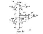
- FIG. An example of a circuit configuration of a comparative example when the diaphragm has no breakage and there is no pressure difference between the front and back of the diaphragm is shown.
- An example of a circuit configuration of a comparative example when the third region and the fourth region of the diaphragm are broken is shown.
- An example of a circuit configuration of a comparative example when the first region and the third region of the diaphragm are broken is shown.
- An example of the circuit structure of the pressure sensor 100 in embodiment of this invention is shown.
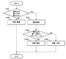
- FIG. 6 is a flowchart showing an example of a failure detection process by the pressure sensor 100. Another example of the circuit configuration of the pressure sensor 100 having a voltage control unit will be shown. An example of failure detection by the pressure sensor 100 according to the embodiment of the present invention is shown.
- FIG. 1 shows an example in which the pressure sensor 100 according to the embodiment of the present invention is applied to pressure detection of a pressure medium.
- the pressure sensor 100 shown in FIG. 1 is a relative pressure sensor.
- the pressure sensor 100 measures the differential pressure between the pressure of the first pressure medium 11 in the first chamber 10 and the pressure of the second pressure medium 21 in the second chamber 20.
- the first pressure medium 11 and the second pressure medium 21 may be gas or liquid.
- the pressure sensor 100 is used, for example, for engine control of an automobile or pressure control in a fuel tank.
- the present invention is not limited to the relative pressure sensor, but can be applied to an absolute pressure sensor in which the second chamber 20 is a vacuum reference chamber sealed with silicon or the like.
- the pressure sensor 100 includes a base material 110 such as glass and a semiconductor substrate 120.
- the semiconductor substrate 120 is, for example, a silicon semiconductor substrate.
- the semiconductor substrate 120 has a recess 121 formed on the back surface side.
- the bottom surface of the concave portion 121 constitutes a thin plate-shaped diaphragm 122 having a thickness of 10 ⁇ m or more and about 50 ⁇ m.
- the diaphragm 122 has a thin semiconductor thin plate shape whose periphery is held by a thick semiconductor substrate. Therefore, when it receives the pressure of the first pressure medium 11 and the second pressure medium 21, it is easily deformed. The pressure can be detected by a change in the output of a bridge circuit formed of a gauge resistor provided on the diaphragm 122. The bridge circuit will be described later.
- the first pressure medium 11 and the second pressure medium 21 are separated by a diaphragm 122.
- the surface of the diaphragm 122 serves as a pressure receiving surface.
- the surface of the diaphragm 122 may be covered with a protective material 30 such as gel.
- the protective material 30 is provided only on the first chamber 10 side, but unlike this example, the protective material may be provided on the back surface side of the diaphragm 122 of the second chamber 20.
- the pressure sensor 100 immediately detects the damage of the diaphragm 122 and gives an alarm to an external control unit or the like. The external control unit shuts down the system, if necessary, or informs the user that repair is required.
- FIG. 2 shows an example of the bridge circuit 130 of the pressure sensor 100.
- the pressure sensor 100 includes the bridge circuit 130 shown in FIG.
- the bridge circuit 130 includes four resistance elements 124-1, 124-2, 124-3, and 124-4 provided on the diaphragm 122.
- the bridge circuit 130 may form a Wheatstone bridge.
- the four resistance elements 124-1, 124-2, 124-3, and 124-4 are referred to as gauge resistance or piezo resistance.
- the adjacent resistance elements 124 are connected by the connecting portions 125a, 125b, 125c, 125d provided on the semiconductor substrate 120.
- the high potential side end portion A of the resistance element 124-1 is electrically connected to the high potential side end portion C of the resistance element 124-2 by the connecting portion 125a.
- the connecting portion 125a is electrically connected to the high voltage side terminal 126 to which the high voltage side voltage VH is applied.
- the low potential side end portion F of the resistance element 124-3 is electrically connected to the low potential side end portion H of the resistance element 124-4 by the connecting portion 125b.
- the connecting portion 125b is electrically connected to the low voltage side terminal 127 to which the low voltage side voltage VL is applied.
- the resistance element 124-1 and the resistance element 124-3 are electrically connected in series by the connecting portion 125c.
- the connecting portion 125c is electrically connected to the first intermediate potential terminal 128 that functions as the first output terminal Out1.
- the resistance element 124-2 and the resistance element 124-4 are electrically connected in series by the connecting portion 125d.
- the connecting portion 125d is electrically connected to the second intermediate potential terminal 129 that functions as the second output terminal Out2.
- FIG. 3 is an example of a plan view of the pressure sensor 100.
- the semiconductor substrate 120 is, for example, a P-type silicon semiconductor substrate.
- An N well region may be formed on the surface side of the diaphragm 122.
- the P-type diffusion region 132 is formed in most of the N well region.
- the P type diffusion region 132 is formed as a diffusion region shallower than the N well region.
- the adjacent P type diffusion region 132 is separated by the LOCOS oxide film 134 into a plurality of P type diffusion regions 132a, 132b, 132c, 132d.
- four resistance elements 124-1, 124-2, 124-3, and 124-4 are formed in a part of the P-type diffusion region 132.
- Each resistance element may be a diffusion resistance having a limited width separated by a LOCOS oxide film 136.
- Adjacent P-type diffusion regions 132a and 132c are electrically connected via a resistance element 124-1, and the portions other than the resistance element 124-1 are electrically isolated from each other by a LOCOS oxide film 134.
- Adjacent P-type diffusion regions 132a and 132d are electrically connected via a resistance element 124-2, and a portion other than the resistance element 124-2 is electrically separated by a LOCOS oxide film 134.
- Adjacent P-type diffusion regions 132c and 132b are electrically connected via a resistance element 124-3, and the portion other than the resistance element 124-3 is electrically isolated by a LOCOS oxide film 134.
- Adjacent P-type diffusion regions 132b and 132d are electrically connected via a resistance element 124-4, and a portion other than the resistance element 124-4 is electrically isolated by a LOCOS oxide film 134.
- the P-type diffusion regions 132a, 132b, 132c, 132d correspond to the connecting portions 125a, 125b, 125c, 125d shown in FIG. 2, respectively.
- the connecting portion 125a is electrically connected to the high voltage side terminal 126.
- the connecting portion 125b is electrically connected to the low voltage side terminal 127 to which the low voltage side voltage VL is applied.
- the connecting portion 125c is electrically connected to the first intermediate potential terminal 128 that functions as the first output terminal Out1.
- the connecting portion 125d is electrically connected to the second intermediate potential terminal 129 that functions as the second output terminal Out2.
- the high-voltage side terminal 126, the low-voltage side terminal 127, the first intermediate potential terminal 128, and the second intermediate potential terminal 129 may be formed not on the diaphragm 122 but in a peripheral region surrounding the diaphragm 122.
- the bottom surface side of the semiconductor substrate 120 may be applied to VL, and the N well on the front surface side of the diaphragm of the semiconductor substrate 120 may be applied to VH.
- the conductivity type and the configuration are not limited to the above case.
- FIG. 4 shows an example of a circuit configuration of a comparative example when the diaphragm 122 has no breakage and there is no pressure difference between the front and back of the diaphragm 122.
- the pressure sensor 101 in the comparative example includes a differential amplifier 141.
- the first input terminal of the differential amplifier 141 is connected to the first intermediate potential terminal 128 that functions as the first output terminal Out1 of the bridge circuit 130, and the second input terminal of the differential amplifier 141 is the second input terminal of the bridge circuit 130. It is connected to the second intermediate potential terminal 129 which functions as the output terminal Out2.
- the resistance elements 124-1 to 124-4 are arranged on the diaphragm 122 as gauge resistors (piezoresistors), and the bridge circuit 130 is configured by these gauge resistors.
- the potential difference between the first intermediate potential terminal 128 and the second intermediate potential terminal 129 of the bridge circuit 130 changes according to the magnitude of pressure.
- the first intermediate potential terminal 128 is electrically connected to the first input terminal of the differential amplifier 141, and the second intermediate potential terminal 129 is input to the second input terminal of the differential amplifier 141.
- the differential amplifier 141 amplifies the potential difference between the first intermediate potential terminal 128 and the second intermediate potential terminal 129 and converts the amplified signal into a digital signal.
- a voltage of (VH + VL) / 2 is applied to the first input terminal and the second input terminal of the differential amplifier 141, respectively.
- VL 0V
- a half-value voltage of VH is applied to each of the first input terminal and the second input terminal.
- VH is 4V
- a voltage of 2V is input to each of the first input terminal and the second input terminal of the differential amplifier 141.
- the differential output of the differential amplifier 141 is 0.
- a voltage of several tens mV (20 mV to 40 mV) is applied between the first intermediate potential terminal 128 and the second intermediate potential terminal 129.
- a voltage difference occurs.
- a region between the high-voltage side terminal 126 and the first intermediate potential terminal 128 is a first region (denoted as (1)), and a region between the high-voltage side terminal 126 and the second intermediate potential terminal 129.
- the region is the second region (denoted as (2)), the region between the first intermediate potential terminal 128 and the low voltage side terminal 127 is the third region (denoted as (3)), the second intermediate potential terminal 129 and the low voltage side.
- An area between the terminal 127 and the terminal 127 is referred to as a fourth area (denoted by (4)).
- FIG. 5 shows an example of a circuit configuration of a comparative example when the third region ((3)) and the fourth region ((4)) of the diaphragm 122 are broken.
- the differential amplifier 141 has a first input terminal and a second input terminal, respectively.
- a voltage of VH is applied.
- a voltage of 4V is applied to each of the first input terminal and the second input terminal of the differential amplifier 141, and the differential output of the differential amplifier 141 is zero. Therefore, the differential output of the differential amplifier 141 is the same as that shown in FIG. It is difficult to detect the occurrence of a failure only from the differential output.
- the first output at the first output terminal and the second output at the second output terminal of the bridge circuit 130 are 4 V, respectively, which is different from the normal case shown in FIG.
- FIG. 6 shows an example of a circuit configuration of a comparative example when the first region ((1)) and the third region ((3)) of the diaphragm 122 are broken.
- the first intermediate potential terminal 128 that functions as the first output terminal Out1 becomes open (OPEN) and becomes in a floating state.
- the voltage of the second intermediate potential terminal 129 becomes 2V.
- the differential output of the differential amplifier 141 is 0.
- the differential output of the differential amplifier 141 is the same as that shown in FIG. It is difficult to detect the occurrence of a failure only from the differential output.
- the first output and the second output terminal (the second intermediate potential terminal 129) of the first output terminal (first intermediate potential terminal 128) of the bridge circuit 130 provided in the diaphragm 122 It may be difficult to detect the abnormality only by the difference (potential difference) from the second output in ().
- the first output at the first output terminal and the second output at the second output terminal are 4 V, respectively, which is different from the normal case shown in FIG.
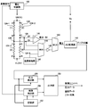
- FIG. 7 shows an example of a circuit configuration of the pressure sensor 100 according to the embodiment of the present invention.
- the pressure sensor 100 includes a bridge circuit 130, an AD converter 142, and a failure detection unit 150.
- the AD converter 142 detects the first output at the first output terminal (first intermediate potential terminal 128) and the second output at the second output terminal (second intermediate potential terminal 129) of the bridge circuit 130, respectively. It is an example of a part.
- the failure detection unit 150 detects a failure of the bridge circuit 130 based on the detection result of the detection unit. In this example, the failure detection unit 150 detects a failure of the bridge circuit 130 based on the output result of the AD converter 142.
- the pressure sensor 100 of this example includes a differential amplifier 141, a first multiplexer 143, a second multiplexer 144, and a buffer 145.
- the first multiplexer 143 and the second multiplexer 144 may be switching circuits.
- the first multiplexer 143 receives not only the amplifier output of the differential amplifier 141 but also the first output of the first intermediate potential terminal 128 and the second output of the second intermediate potential terminal 129.
- the amplifier output of the differential amplifier 141 is a signal obtained by amplifying the difference between the first output of the first intermediate potential terminal 128 and the second output of the second intermediate potential terminal 129.
- the pressure sensor 100 shown in FIG. 7 may include a temperature detection unit 146.
- the resistance values of the resistance elements 124-1, 124-2, 124-3, and 124-4 depend on the temperature. Therefore, the temperature detection unit 146 outputs a temperature signal corresponding to the detected temperature in order to correct the change in the resistance value due to the temperature and accurately measure the pressure.
- the temperature signal is input to the second multiplexer 144 by the temperature detection unit 146. Then, the first output at the first output terminal (first intermediate potential terminal 128) of the bridge circuit 130 and the second output at the second output terminal (second intermediate potential terminal 129) are input to the second multiplexer 144. You may
- the output terminal of the second multiplexer 144 may be connected to the buffer 145.
- the second multiplexer 144 functions as a selection unit that selects the first output, the second output, and the temperature signal in time division and inputs them to the buffer 145.
- the buffer 145 inputs the input signal to the AD converter 142.
- the output of the buffer 145 may be input to the AD converter 142 via the first multiplexer 143.
- the buffer 145 may be a driver that provides a driving force.
- the first output of the first intermediate potential terminal 128 and the second output of the second intermediate potential terminal 129 may be directly input to the AD converter 142 without passing through the buffer 145.
- the first multiplexer 143 and the second multiplexer 144 finally switch the signal input to the AD converter 142.
- the first multiplexer 143 and the second multiplexer 144 may receive the timing signal from the failure detection unit 150 and switch the signal input to the AD converter 142.
- the AD converter 142 time-divisionally AD-converts the first output of the first intermediate potential terminal 128 and the second output of the second intermediate potential terminal 129.
- the AD converter 142 may always operate in a time division manner.
- the first output and the second output may be operated in a time division manner at the time of starting the system of an automobile engine or the like in which the pressure sensor 100 is used.
- a fixed diagnosis period may be set, and the failure diagnosis process based on the first output and the second output may be executed for each diagnosis period.
- the first multiplexer 143 and the second multiplexer 144 switch the signals input to the AD converter 142, so that the AD converter 142 outputs the first output, the second output, the first output, and the second output.
- the temperature signal may be AD-converted in a time division manner.
- the difference between the first output and the second output may be a signal whose difference is amplified by the differential amplifier 141.
- the signal that the AD converter 142 performs time-division AD conversion is not limited to this case. Other signals may be included as signals to be time-divided and AD-converted, and some signals may be omitted.
- the AD converter 142 may time-divisionally AD-convert the first output, the second output, and the difference between the first output and the second output.
- the pressure sensor 100 may include a failure detection unit 150, a storage unit 152, an output unit 153, and a pressure calculation unit 154.
- the output signal from the AD converter 142 is received by the failure detection unit 150 and the pressure calculation unit 154.
- the pressure calculator 154 calculates the pressure based on the digital value of the difference between the first output and the second output. Specifically, the amplifier output obtained by amplifying the difference between the first output and the second output by the differential amplifier 141 is AD-converted into a digital value.
- the pressure calculator 154 may calculate the pressure based on the digital value. At this time, the pressure calculation unit 154 may correct the temperature of the pressure data based on the digitized temperature data.
- the output unit 153 may output the calculated pressure data and temperature data.
- the failure detection unit 150 may detect the failure of the bridge circuit 130 based on the detection result of the AD converter 142 that functions as the detection unit.
- the failure detection unit 150 may supply a signal for switching the output signals of the first multiplexer 143 and the second multiplexer 144 to the first multiplexer 143 and the second multiplexer 144.
- At least one of the first output of the first intermediate potential terminal 128 and the second output of the second intermediate potential terminal 129 has an intermediate voltage ((VH + VL) / 2) between the high voltage side (VH) and the low voltage side (VL).
- the failure detection unit 150 determines that the bridge circuit 130 has a failure.
- the predetermined range may be the intermediate voltage ((VH + VL) / 2) ⁇ ⁇ .
- ⁇ may be set to a value larger than the fluctuation range (mV range) due to pressure.
- (VH + VL) / 2) is 2V
- ⁇ may be 0.1V or more and 0.5V or less.
- the upper limit value and the lower limit value may be stored in advance in the storage area of the storage unit 152.
- the upper limit value and the lower limit value to be set are not limited to these cases, and may be set appropriately so as not to be affected by noise or the like.
- the failure detection unit 150 may include a comparison circuit that compares the digital values of the first output and the second output, which are AD-converted by the AD converter 142, with the respective upper limit value and lower limit value. When at least one of the digital values of the first output and the second output is not within the upper and lower limit range, the failure detection unit 150 determines that the bridge circuit 130 is in failure, assuming that the failure determination condition is satisfied. You can do it.
- the output unit 153 may output a signal indicating that an error has occurred to an external control unit.
- the external control unit is, for example, an ECU (engine control unit) in an automobile.
- the first output of the first intermediate potential terminal 128 and the second output of the second intermediate potential terminal 129 are both (VH + VL) / 2. ) Within ⁇ ⁇ .
- the first input terminal and the second input terminal of the differential amplifier 141 are A voltage of VH (4V) is applied to each of and.
- At least one of the first output of the first intermediate potential terminal 128 and the second output of the second intermediate potential terminal 129 has an intermediate voltage ((VH + VL) / (VH + VL) /) between the high-voltage side voltage (VH) and the low-voltage side voltage (VL). It is outside the predetermined range including 2).
- the failure detection unit 150 may determine that the bridge circuit 130 has a failure.
- the pressure sensor 100 having the voltage control unit may be employed to detect a failure.
- FIG. 8 shows an example of a circuit configuration of the pressure sensor 100 having a voltage controller.
- the pressure sensor 100 includes a voltage controller 155.
- the failure detection unit 150 sends a voltage variation command to the voltage control unit 155.
- the voltage control unit 155 that has received the variation command sets at least one of the high-voltage side voltage VH and the low-voltage side voltage VL so that the intermediate voltage between the high-voltage side voltage and the low-voltage side voltage, that is, (VH + VL) / 2 changes. Change.
- the high voltage VH is changed to 4V, 3V and 2V.
- At least one of the high-voltage side voltage VH and the low-voltage side voltage VL may be sequentially changed at time-division timing.
- the failure detection unit 150 detects a failure in the bridge circuit 130 based on a change in at least one of the first output and the second output when the intermediate voltage is changed. Specifically, the failure detection unit 150 determines in advance whether the voltage fluctuation of the first output of the first intermediate potential terminal 128 or the voltage fluctuation of the second output of the second intermediate potential terminal 129 when the intermediate voltage is changed. If it is within the range, it may be determined that the bridge circuit 130 is out of order. The range is smaller than the fluctuation range of the intermediate voltage.
- FIG. 9 is a flowchart showing an example of failure detection processing by the pressure sensor 100.
- the failure detection unit 150 detects a failure of the bridge circuit 130 based on the output result of the AD converter 142. Failure detection unit 150 determines that at least one of the first output and the second output is outside a predetermined range including the intermediate voltage (VH + VL) / 2 between high-voltage side voltage VH and low-voltage side voltage VL (step S101). : NO), it is determined that the bridge circuit 130 has failed (step S102).
- the failure detecting unit determines that the bridge circuit 130 is out of order (step S102). Therefore, if the first output or the second output is outside the predetermined range, it is possible to determine the failure without waiting for the result of the voltage fluctuation process or the like.
- the failure detection unit 150 sends a voltage fluctuation instruction to the voltage control unit 155 (step S103).
- the voltage control unit 155 that has received the voltage fluctuation instruction changes at least one of the high voltage side voltage VH and the low voltage side voltage VL so that the intermediate voltage (VH + VL) / 2 of the high voltage side voltage and the low voltage side voltage changes. .
- the high-voltage side voltage VH is changed in multiple stages of 4V, 3V, and 2V (step S103).
- the voltage control unit 155 changes the high voltage side voltage VH to the high voltage side voltage VH ′ and the low voltage side voltage VL to the low voltage side voltage VL ′, if the bridge circuit 130 is normal, the high voltage side voltage and the low voltage side The intermediate voltage (VH + VL) / 2 of the side voltage changes to (VH '+ VL') / 2. Then, the first output and the second output change from (VH + VL) / 2 to (VH '+ VL') / 2.
- the intermediate voltage (VH + VL) / 2 between the high voltage side voltage and the low voltage side voltage is (VH ' Even if it changes to + VL ′) / 2, the fluctuation of the first output and the fluctuation of the second output do not change to (VH ′ + VL ′) / 2.
- step S104 determines that the bridge It is determined that the circuit 130 is normal without any failure (step S105). On the other hand, the failure detection unit 150 does not vary the first output and the second output according to the variation range from (VH + VL) / 2 to (VH '+ VL') / 2 (step S104: NO). If it is within the predetermined range, it is determined that the bridge circuit 130 has failed and is abnormal (step S106).
- the failure detection unit 150 changes the intermediate voltage when the first output or the second output deviates from the preset lower limit upper limit range or even within the preset lower limit upper limit range.
- the change in at least one of the first output and the second output at this time is smaller than a predetermined value, it may be determined that the bridge circuit 130 is out of order.
- the output from the bridge circuit 130 is changed by changing at least one of the high voltage side voltage VH and the low voltage side voltage VL.
- the first output of the first intermediate potential terminal 128 and the second output of the second intermediate potential terminal 129 exhibit a value of about 2V.
- the high-voltage side voltage VH is changed to 3V
- the voltage control unit 155 may also change the high-voltage power supply voltage (driving voltage) Va of the AD converter 142 to adjust the dynamic range of the AD converter 142.
- FIG. 10 shows another example of the circuit configuration of the pressure sensor 100 having a voltage controller.
- the high voltage VH of the bridge circuit 130 may be input to the AD converter 142 as the high power voltage Va.
- the voltage control unit 155 does not need to separately adjust the high-voltage power supply voltage (driving voltage) Va of the AD converter 142.
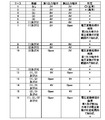
- FIG. 11 shows an example of failure detection by the pressure sensor 100 according to the embodiment of the present invention.
- the disconnection column indicates the area where the disconnection occurs in the first area ((1)), the second area ((2)), the third area ((3)), and the fourth area ((4)).
- the column of the first output terminal shows the voltage value of the first output of the first intermediate potential terminal 128, and the column of the second output terminal shows the voltage value of the second output of the second intermediate potential terminal 129.
- the failure detection unit 150 does not detect a failure.
- the pressure sensor 100 has an AD converter 142 that detects the first output of the first intermediate potential terminal 128 and the second output of the second intermediate potential terminal 129, respectively. Then, the failure detection unit 150 detects a failure of the bridge circuit 130 based on the detection result of the AD converter 142. Therefore, as in the eleventh case of FIG. 11, it is possible to accurately determine the failure of the bridge circuit 130 even in the case where it is difficult to determine the failure based on only the difference between the first output and the second output. Note that, as shown in FIG. 11, the broken portion of the bridge circuit 130 may be specified based on the values of the first output and the second output.
- the pressure sensor 100 can determine the failure by measuring the output change when any one of the voltages applied to the high voltage side terminal 126 and the low voltage side terminal 127 of the bridge circuit 130 is changed.
Landscapes
- Physics & Mathematics (AREA)
- General Physics & Mathematics (AREA)
- Measuring Fluid Pressure (AREA)
- Pressure Sensors (AREA)
Abstract
ダイアフラムが破損してブリッジ回路が故障した場合には、破損したことを早期に検出する。圧力センサは、ダイアフラムが設けられた基板と、ダイアフラムに設けられた4つの抵抗素子を含み、高圧側電圧および低圧側電圧が印加され、2つの出力端子を有するブリッジ回路と、ブリッジ回路の第1の出力端子における第1の出力と、第2の出力端子における第2の出力をそれぞれ検出する検出部と、検出部における検出結果に基づいて、ブリッジ回路の故障を検出する故障検出部とを備える。
Description
本発明は、圧力センサに関する。
半導体基板に形成されたダイアフラムを有する圧力センサが広く用いられている。ダイアフラムには、高圧側電圧および低圧側電圧が印加されるブリッジ回路を配置される。ブリッジ回路は、2つの出力端子を有しており、この2つの出力端子間の電圧差に基づいて、ブリッジ回路を構成する抵抗の変化を検出する。ダイアフラムに対して過度の圧力が加わった場合にダイアフラムが破損する可能性があることが知られている(例えば、特許文献1参照)。
[先行技術文献]
[特許文献]
[特許文献1] 特開2009-264890号公報
[先行技術文献]
[特許文献]
[特許文献1] 特開2009-264890号公報
圧力センサにおいて、ダイアフラムが破損した場合には、破損したことを早期に検出することが好ましい。
本発明の第1の態様においては、圧力センサが提供される。圧力センサは、基板を備えてよい。基板は、ダイアフラムが設けられてよい。圧力センサは、ブリッジ回路を備えてよい。ブリッジ回路は、4つの抵抗素子を含んでよい。4つの抵抗素子は、ダイアフラムに設けられてよい。ブリッジ回路には、高圧側電圧および低圧側電圧が印加されてよい。圧力センサは、検出部を備えてよい。検出部は、ブリッジ回路の第1の出力端子における第1の出力と、第2の出力端子における第2の出力をそれぞれ検出してよい。圧力センサは、故障検出部を備えてよい。故障検出部は、検出部における検出結果に基づいて、ブリッジ回路の故障を検出してよい。
故障検出部は、第1の出力および第2の出力の少なくとも一方が、高圧側電圧と低圧側電圧の中間電圧を含む予め定められた範囲外の場合に、ブリッジ回路が故障していると判定してよい。
圧力センサは、電圧制御部を更に備えてよい。電圧制御部は、高圧側電圧と低圧側電圧の中間電圧が変化するように、高圧側電圧と低圧側電圧の少なくとも一方を変化させてよい。故障検出部は、中間電圧を変化させたときの第1の出力および第2の出力の少なくとも一方の変化に基づいて、ブリッジ回路の故障を検出してよい。
検出部はAD変換器を有してよい。AD変換器は、第1の出力および第2の出力を時分割でAD変換してよい。
AD変換器は、第1の出力、第2の出力、および、第1の出力と第2の出力との差分を時分割でAD変換してよい。圧力センサは、圧力算出部を更に備えてよい。圧力算出部は、第1の出力と第2の出力との差分のデジタル値に基づいて圧力を算出してよい。
圧力センサは、温度検知部を更に備えてよい。温度検知部は、検知温度に応じた温度信号を出力してよい。AD変換器は、第1の出力、第2の出力、第1の出力と第2の出力との差分、および、温度信号を時分割でAD変換してよい。
圧力センサは、バッファを備えてよい。バッファは、入力される信号をAD変換器に入力してよい。圧力センサは、選択部を備えてよい。選択部は、第1の出力、第2の出力、および、温度信号を時分割で選択してバッファに入力してよい。
ブリッジ回路の高圧側電圧が、高圧側電源電圧としてAD変換器に入力されてよい。
なお、上記の発明の概要は、本発明の必要な特徴の全てを列挙したものではない。また、これらの特徴群のサブコンビネーションもまた、発明となりうる。
以下、発明の実施の形態を通じて本発明を説明するが、以下の実施形態は請求の範囲にかかる発明を限定するものではない。また、実施形態の中で説明されている特徴の組み合わせの全てが発明の解決手段に必須であるとは限らない。
図1は、本発明の実施形態の圧力センサ100を圧力媒体の圧力検知に適用した例を示す。図1に示される圧力センサ100は、相対圧センサである。圧力センサ100は、第1室10内の第1圧力媒体11の圧力と第2室20内の第2圧力媒体21の圧力との差圧を測定する。第1圧力媒体11および第2圧力媒体21は、気体または液体であってよい。圧力センサ100は、一例において、自動車のエンジン制御または燃料タンク内の圧力制御に用いられる。但し、本発明は、相対圧センサに限れず、第2室20がシリコン等で封止された真空基準室となっている絶対圧センサにも適用することができる。
圧力センサ100は、ガラス等の基材110と、半導体基板120とを備える。半導体基板120は、例えば、シリコン半導体基板である。半導体基板120は、裏面側に凹部121が形成されている。凹部121の底面は、10μm以上50μm程度の薄板状をしたダイアフラム122を構成する。
ダイアフラム122は、周囲を厚い半導体基板で保持された薄い半導体薄板状となっている。したがって、第1圧力媒体11および第2圧力媒体21の圧力を受けると容易に変形する。ダイアフラム122上に設けたゲージ抵抗で構成されたブリッジ回路の出力変化で圧力を検知することができる。ブリッジ回路については後述する。
第1圧力媒体11と第2圧力媒体21とは、ダイアフラム122によって隔たれている。ダイアフラム122の表面が受圧面となる。ダイアフラム122を保護するために、ダイアフラム122の表面は、ゲル等の保護材30で覆われていてよい。本例では第1室10側にのみ保護材30が設けられているが、本例と異なり、第2室20のダイアフラム122の裏面側にも、保護材が設けられてもよい。
凍結破損またはサージ圧等に起因して、ダイアフラム122に過度の圧力が加わる場合を完全に予防することは困難である。ダイアフラム122が破損した場合には、第1圧力媒体11および第2圧力媒体21を隔てることができない。第2圧力媒体21の圧力が、第1圧力媒体11の圧力より高い場合には、第2圧力媒体21が第1圧力媒体11側に漏れ出す可能性がある。したがって、ダイアフラム122が破損した場合には、圧力センサ100は、ダイアフラム122の破損を早急に検知し、外部の制御ユニット等に警報する。外部の制御ユニットは、必要に応じて、システムを停止し、または利用者に修理が必要であることを知らせる。
図2は、圧力センサ100のブリッジ回路130の一例を示す。圧力センサ100は、図2に示されるブリッジ回路130を備える。ブリッジ回路130は、ダイアフラム122に設けられた4つの抵抗素子124-1、124-2、124-3、および124-4を含む。ブリッジ回路130は、ホイーストンブリッジを構成してよい。4つの抵抗素子124-1、124-2、124-3、および124-4は、ゲージ抵抗またはピエゾ抵抗と称される。隣接する抵抗素子124間は、半導体基板120に設けられた連結部125a、125b、125c、125dによって接続されている。
図2に示されるとおり、抵抗素子124-1の高電位側端部Aは、連結部125aによって抵抗素子124-2の高電位側端部Cに電気的に接続される。連結部125aは、高圧側電圧VHが印加される高圧側端子126に電気的に接続される。一方、抵抗素子124-3の低電位側端部Fは、連結部125bによって抵抗素子124-4の低電位側端部Hに電気的に接続される。連結部125bは、低圧側電圧VLが印加される低圧側端子127に電気的に接続される。
抵抗素子124-1と抵抗素子124-3とは、連結部125cによって電気的に直列に接続されている。連結部125cは、第1出力端子Out1として機能する第1中間電位端子128に電気的に接続される。抵抗素子124-2と抵抗素子124-4とは、連結部125dによって電気的に直列に接続されている。連結部125dは、第2出力端子Out2として機能する第2中間電位端子129に電気的に接続される。
図3は、圧力センサ100の平面図の一例である。半導体基板120は、例えばP型シリコン半導体基板である。ダイアフラム122表面側には、Nウェル領域が形成されてよい。Nウェル領域の大部分にP型拡散領域132が形成される。P型拡散領域132は、Nウェル領域より浅い拡散領域として形成される。Nウェル領域の表面では、隣接するP型拡散領域132がLOCOS酸化膜134によって、複数のP型拡散領域132a、132b、132c、132dに分離される。さらに、P型拡散領域132の一部には、4つの抵抗素子124-1、124-2、124-3、および124-4が形成される。各抵抗素子は、LOCOS酸化膜136で分離されて幅が限定された拡散抵抗であってよい。
隣接するP型拡散領域132a、132cは、抵抗素子124-1を介して電気的に接続され、抵抗素子124-1以外の部分は、LOCOS酸化膜134によって互いに電気的に分離される。隣接するP型拡散領域132a、132dは、抵抗素子124-2を介して電気的に接続され、抵抗素子124-2以外の部分は、LOCOS酸化膜134によって電気的に分離される。隣接するP型拡散領域132c、132bは、抵抗素子124-3を介して電気的に接続され、抵抗素子124-3以外の部分は、LOCOS酸化膜134によって電気的に分離される。隣接するP型拡散領域132b、132dは、抵抗素子124-4を介して電気的に接続され、抵抗素子124-4以外の部分は、LOCOS酸化膜134によって電気的に分離される。
したがって、本例では、P型拡散領域132a、132b、132c、132dが、それぞれ図2に示される連結部125a、125b、125c、125dに相当する。連結部125aは、高圧側端子126に電気的に接続される。連結部125bは、低圧側電圧VLが印加される低圧側端子127に電気的に接続される。連結部125cは、第1出力端子Out1として機能する第1中間電位端子128に電気的に接続される。連結部125dは、第2出力端子Out2として機能する第2中間電位端子129に電気的に接続される。
高圧側端子126、低圧側端子127、第1中間電位端子128、および第2中間電位端子129は、ダイアフラム122上ではなく、ダイアフラム122を取り囲む周辺領域において形成されてよい。半導体基板120の底面側がVLに印加され、半導体基板120のダイアフラムの表面側のNウェルがVHに印加されてよい。但し、導電型および構成は、上記の場合に限られない。
図4は、ダイアフラム122に破断がなくダイアフラム122の表裏に圧力差がない場合の比較例の回路構成の一例を示す。図4に示されるとおり、比較例における圧力センサ101は、差動増幅器141を備える。差動増幅器141の第1入力端は、ブリッジ回路130の第1出力端子Out1として機能する第1中間電位端子128に接続され、差動増幅器141の第2入力端は、ブリッジ回路130の第2出力端子Out2として機能する第2中間電位端子129に接続される。
ダイアフラム122に、ゲージ抵抗(ピエゾ抵抗)として、抵抗素子124-1から124-4が配置され、これらゲージ抵抗でブリッジ回路130が構成されている。ブリッジ回路130の第1中間電位端子128と第2中間電位端子129との電位差が、圧力の大きさ応じて変化する。第1中間電位端子128を差動増幅器141の第1入力端に電気的に接続し、第2中間電位端子129を差動増幅器141の第2入力端に入力する。差動増幅器141は、第1中間電位端子128と第2中間電位端子129との電位差を増幅し、増幅した信号をデジタル信号に変換する。
ダイアフラム122に破断がなくダイアフラム122の表裏に圧力差がない場合には、差動増幅器141の第1入力端と第2入力端とに、それぞれ(VH+VL)/2の電圧が印加される。本例では、VL=0Vであるので、第1入力端と第2入力端とに、それぞれVHの半値の電圧が印加される。本例では、VHが4Vであるので、差動増幅器141の第1入力端と第2入力端とに、それぞれ2Vの電圧が入力される。差動増幅器141の差動出力は、0である。
なお、ダイアフラム122に破断がなくダイアフラム122の表裏に圧力差がある場合には、第1中間電位端子128と第2中間電位端子129との間には、数十mV程度(20mV~40mV)の電圧差が生じる。なお、ブリッジ回路130において、高圧側端子126と第1中間電位端子128との間の領域を第1領域((1)と表記)、高圧側端子126と第2中間電位端子129との間の領域を第2領域((2)と表記)、第1中間電位端子128と低圧側端子127との間の領域を第3領域((3)と表記)、第2中間電位端子129と低圧側端子127との間の領域を第4領域((4)と表記)とする。
図5は、ダイアフラム122の第3領域((3))および第4領域((4))がそれぞれ破断した場合の比較例の回路構成の一例を示す。図5に示されるとおり、第3領域((3))および第4領域((4))が共に破断した場合には、差動増幅器141の第1入力端と第2入力端とに、それぞれVHの電圧が印加される。本例は、差動増幅器141の第1入力端と第2入力端とにそれぞれ4Vの電圧が印加され、差動増幅器141の差動出力は、0である。したがって、差動増幅器141の差動出力は、図4に示される場合と同じである。差動出力のみからは、故障発生を検出することが困難である。一方、ブリッジ回路130の第1出力端子における第1出力と、第2出力端子における第2出力はそれぞれ、4Vであり、図4に示される正常な場合と異なっている。
図6は、ダイアフラム122の第1領域((1))および第3領域((3))がそれぞれ破断した場合の比較例の回路構成の一例を示す。図6に示されるように、第1領域および第3領域が共に破断した場合には、第1出力端子Out1として機能する第1中間電位端子128は、オープン(OPEN)となり、フローティング状態となる。第2中間電位端子129の電圧は、2Vとなる。フローティング状態である第1中間電位端子128の電圧が、たまたま、2Vとなる場合には、差動増幅器141の第1入力端と第2入力端とには、それぞれ2Vの電圧が印加される。したがって、差動増幅器141の差動出力は、0である。この場合も、差動増幅器141の差動出力は、図4に示される場合と同じである。差動出力のみからは、故障発生を検出することが困難である。
以上の比較例の圧力センサ101のように、ダイアフラム122に設けられたブリッジ回路130の第1出力端子(第1中間電位端子128)における第1出力と第2出力端子(第2中間電位端子129)における第2出力との差分(電位差)のみでは、異常を検知することが困難な場合がある。一方、電位差のみならず、第1中間電位端子128の第1出力、および第2中間電位端子129の第2出力をそれぞれ検出する場合には、圧力センサ101が正常か否かを判断できる場合がある。例えば、図5の場合においても、第1出力端子における第1出力と、第2出力端子における第2出力はそれぞれ、4Vであり、図4に示される正常な場合と異なっている。
図7は、本発明の実施形態における圧力センサ100の回路構成の一例を示す。圧力センサ100は、ブリッジ回路130、AD変換器142、および故障検出部150を備える。AD変換器142は、ブリッジ回路130の第1出力端子(第1中間電位端子128)における第1出力と、第2出力端子(第2中間電位端子129)の第2出力とをそれぞれ検出する検出部の一例である。故障検出部150は、検出部における検出結果に基づいて、ブリッジ回路130の故障を検出する。本例では、故障検出部150は、AD変換器142における出力結果に基づいて、ブリッジ回路130の故障を検出する。
本例の圧力センサ100は、差動増幅器141、第1マルチプレクサ143、第2マルチプレクサ144、およびバッファ145を備える。第1マルチプレクサ143および第2マルチプレクサ144は、切替回路であってよい。第1マルチプレクサ143は、差動増幅器141によるアンプ出力のみならず、第1中間電位端子128の第1出力と、第2中間電位端子129の第2出力との入力を受ける。差動増幅器141のアンプ出力は、第1中間電位端子128の第1出力と第2中間電位端子129の第2出力との差分を増幅した信号である。
図7に示される圧力センサ100は、温度検知部146を備えてよい。抵抗素子124-1、124-2、124-3、および124-4の抵抗値は、温度に依存する。したがって、温度による抵抗値の変化を補正して正確に圧力を測定するために、温度検知部146は、検知温度に応じた温度信号を出力する。温度検知部146よって温度信号が第2マルチプレクサ144に入力される。そして、ブリッジ回路130の第1出力端子(第1中間電位端子128)における第1出力と、第2出力端子(第2中間電位端子129)の第2出力とが、第2マルチプレクサ144に入力されてよい。
第2マルチプレクサ144の出力端は、バッファ145に接続されてよい。第2マルチプレクサ144は、第1出力と第2出力、および温度信号を時分割で選択してバッファ145に入力する選択部として機能する。バッファ145は、入力された信号をAD変換器142に入力する。本例では、バッファ145の出力は、第1マルチプレクサ143を介してAD変換器142に入力されてよい。バッファ145は、駆動力を与えるドライバであってよい。但し、第1中間電位端子128の第1出力と第2中間電位端子129の第2出力は、バッファ145を経ることなく、そのままAD変換器142に入力されてもよい。
本例では、第1マルチプレクサ143および第2マルチプレクサ144が、最終的にAD変換器142に入力される信号を切り替える。第1マルチプレクサ143および第2マルチプレクサ144は、故障検出部150からのタイミング信号を受けて、AD変換器142に入力される信号を切り替えてよい。
したがって、AD変換器142は、第1中間電位端子128の第1出力と、第2中間電位端子129の第2出力とを時分割でAD変換する。なお、常時、AD変換器142は、時分割で動作してよい。一方、圧力センサ100が用いられる自動車エンジン等のシステム始動時のタイミングにおいて、第1出力と第2出力とを時分割で動作してもよい。また、一定の診断期間が設定されて、診断期間ごとに、第1出力と第2出力とに基づく故障診断処理が実行されてもよい。
本例では、第1マルチプレクサ143および第2マルチプレクサ144がAD変換器142に入力される信号を切り替えることによって、AD変換器142は、第1出力、第2出力、第1出力と第2出力との差分、および温度信号を時分割でAD変換してよい。特に、第1出力と第2出力との差分は、差動増幅器141によって差分を増幅された信号であってよい。AD変換器142が時分割してAD変換する信号は、この場合に限られない。時分割してAD変換する信号として、更に他の信号が含まれてもよく、一部の信号が省略されてもよい。一例において、AD変換器142は、第1出力、第2出力、第1出力と第2出力との差分を時分割でAD変換してもよい。
圧力センサ100は、故障検出部150、記憶部152、出力部153、および圧力算出部154を備えてよい。AD変換器142からの出力信号は、故障検出部150および圧力算出部154が受信する。圧力算出部154は、第1出力と第2出力との差分のデジタル値に基づいて圧力を算出する。具体的には、第1出力と第2出力との差が差動増幅器141によって増幅されたアンプ出力がデジタル値にAD変換される。圧力算出部154は、デジタル値に基づいて圧力を算出してよい。このとき圧力算出部154は、デジタル化された温度データに基づいて、圧力データを温度補正してよい。算出され圧力データおよび温度データは、出力部153が出力してよい。
故障検出部150は、検出部として機能するAD変換器142における検出結果に基づいて、ブリッジ回路130の故障を検出してよい。故障検出部150は、第1マルチプレクサ143および第2マルチプレクサ144の出力信号を切り替えるための信号を第1マルチプレクサ143および第2マルチプレクサ144に供給してよい。
第1中間電位端子128の第1出力と、第2中間電位端子129の第2出力の少なくとも一方が、高圧側電圧(VH)と低圧側電圧(VL)の中間電圧((VH+VL)/2)を含む予め定められた範囲外の場合に、故障検出部150は、ブリッジ回路130が故障をしていると判定する。一例において、予め定められた範囲は、中間電圧((VH+VL)/2)±αであってよい。αは、圧力による変動幅(mVレンジ)よりも大きい値に設定してよい。(VH+VL)/2)が2Vである場合には、αは0.1V以上0.5V以下であってよい。
予め定められた範囲は、αが0.1Vであるとき、下限値が2V-0.1V=1.9Vであり、上限値が2V+0.1V=2.1Vであってよい。上限値および下限値は、記憶部152の記憶領域に予め記憶されてよい。但し、設定される上限値および下限値の値は、これらの場合に限られず、ノイズ等の影響を受けないように適宜に設定されてよい。
故障検出部150は、AD変換器142によってAD変換された第1出力および第2出力のデジタル値をそれぞれの上限値および下限値と比較する比較回路を含んでよい。故障検出部150は、第1出力および第2出力のデジタル値の少なくも一方が、上下限範囲内に含まれない場合に、故障判定条件を満たすとして、ブリッジ回路130が故障していると判定してよい。出力部153は、外部の制御ユニットへエラーが発生したことを示す信号を出力してよい。外部の制御ユニットは、例えば、自動車におけるECU(エンジンコントロールユニット)である。
上述した図4によって説明したとおり、ブリッジ回路が正常の場合には、第1中間電位端子128の第1出力と、第2中間電位端子129の第2出力とは、共に、(VH+VL)/2)±αの範囲内となる。一方、図5を用いて説明したとおり、第3領域((3))および第4領域((4))が共に破断した場合には、差動増幅器141の第1入力端と第2入力端とに、それぞれVH(4V)の電圧が印加される。したがって、第1中間電位端子128の第1出力と、第2中間電位端子129の第2出力の少なくとも一方が、高圧側電圧(VH)と低圧側電圧(VL)の中間電圧((VH+VL)/2)を含む予め定められた範囲外となる。故障検出部150は、ブリッジ回路130が故障していると判定してよい。
一方、上述した図6において説明したとおり、ダイアフラム122の破断によって、第1中間電位端子128と第2中間電位端子129の少なくとも一方がOpen(フローティング)となった場合には、Open(フローティング)となった端子の出力電圧が不定である。この端子の電圧が偶然に、上記の予め定められた範囲、例えば、中間電圧((VH+VL)/2)±αとなる場合があり得る。第1中間電位端子128と第2中間電位端子129の少なくとも一方がOpen(フローティング)となった場合に、故障を検出するために、電圧制御部を有する圧力センサ100を採用してよい。
図8は、電圧制御部を有する圧力センサ100の回路構成の一例を示す。圧力センサ100は、電圧制御部155を備える。故障検出部150は、電圧制御部155に電圧の変動指令を送信する。変動指令を受信した電圧制御部155は、高圧側電圧と低圧側電圧の中間電圧、すなわち、(VH+VL)/2が変化するように、高圧側電圧VHと、低圧側電圧VLとの少なくとも一方を変化させる。例えば、高圧側電圧VHを、4V、3V、2Vと変化させる。順次に時分割のタイミングで、高圧側電圧VHと、低圧側電圧VLとの少なくとも一方を変化させてよい。
故障検出部150は、中間電圧を変化させたときの第1の出力および第2の出力の少なくとも一方の変化に基づいて、ブリッジ回路130の故障を検出する。具体的には、故障検出部150は、中間電圧を変化させたときの第1中間電位端子128の第1出力の電圧変動または第2中間電位端子129の第2出力の電圧変動が、予め定められた範囲内であれば、ブリッジ回路130が故障していると判断してよい。当該範囲は中間電圧の変動幅よりも小さい。
図9は、圧力センサ100による故障検出処理の一例を示すフローチャートである。故障検出部150は、AD変換器142における出力結果に基づいて、ブリッジ回路130の故障を検出する。故障検出部150は、第1の出力および第2の出力の少なくとも一方が、高圧側電圧VHと低圧側電圧VLの中間電圧(VH+VL)/2を含む予め定められた範囲外の場合(ステップS101:NO)、ブリッジ回路130が故障していると判定する(ステップS102)。
例えば、VH=4Vであり、VL=0Vである場合、第1の出力および第2の出力の少なくとも一方が、中間電圧2V±αの範囲外であれば(ステップS101:NO)、故障検出部150は、ブリッジ回路130が故障していると判定する(ステップS102)。したがって、第1出力または第2出力が、予め定められた範囲外であれば、電圧変動処理等の結果を待つことなく、故障を判定することができる。
一方、第1出力または第2出力が、予め定められた範囲内の場合(ステップS101:YES)、故障検出部150は、電圧制御部155に対して電圧変動指示を送信する(ステップS103)。電圧変動指示を受けた電圧制御部155は、高圧側電圧と低圧側電圧の中間電圧(VH+VL)/2が変化するように、高圧側電圧VHと、低圧側電圧VLとの少なくとも一方を変化させる。例えば、高圧側電圧VHを、4V、3V、2Vと複数の段階に変化させる(ステップS103)。
電圧制御部155が、高圧側電圧VHを高圧側電圧VH´に変動させ、低圧側電圧VLを低圧側電圧VL´に変動させた場合、ブリッジ回路130が正常であれば、高圧側電圧と低圧側電圧の中間電圧(VH+VL)/2が(VH´+VL´)/2に変化する。そして、第1出力と第2出力が、(VH+VL)/2から(VH´+VL´)/2へと変化する。一方、第1中間電位端子128と第2中間電位端子129の少なくとも一方がOpen(フローティング)となっている場合には、高圧側電圧と低圧側電圧の中間電圧(VH+VL)/2が(VH´+VL´)/2に変化しても、第1出力の変動と第2出力の変動が(VH´+VL´)/2へと変化しない。
したがって、第1出力と第2出力が、(VH+VL)/2から(VH´+VL´)/2への変動幅に応じて変動する場合は(ステップS104:YES)、故障検出部150は、ブリッジ回路130が故障しておらず正常であると判定する(ステップS105)。一方、故障検出部150は、第1出力と第2出力の変動が、(VH+VL)/2から(VH´+VL´)/2への変動幅に応じて変動せずに(ステップS104:NO)、予め定められた範囲内である場合には、ブリッジ回路130が故障しており異常と判断する(ステップS106)。
以上のとおり、故障検出部150は、第1出力または第2出力が予め設定された下限上限範囲から外れる場合、および予め設定された下限上限値範囲内であっても、中間電圧を変化させたときの第1出力および第2出力の少なくとも一方の変化が予め定められた値に比べて小さい場合には、ブリッジ回路130が故障していると判定してよい。
図9において、高圧側電圧VHと、低圧側電圧VLとの少なくとも一方を変化させることによって、ブリッジ回路130からの出力が変動する。たとえば、高圧側電圧VH=4Vで低圧側電圧VL=0Vの場合に、第1中間電位端子128の第1出力および第2中間電位端子129の第2出力は、2V程度の値を示す。高圧側電圧VHを3Vと変化させた場合には、第1出力および第2出力は、1.5V程度の値を示す。したがって、AD変換器142においては、高圧側電圧VH=4V(2進数で4095)のとき、第1出力および第2出力のデジタル値は2V(2進数で2048)だったにもかかわらず、高圧側電圧VHを3Vと変化させた場合には、第1出力および第2出力のデジタル値が、1365に変化してしまう。これを防止するために、電圧制御部155は、AD変換器142の高圧側電源電圧(駆動電圧)Vaについても変動させてAD変換器142のダイナミックレンジについても調整してよい。
図10は、電圧制御部を有する圧力センサ100の回路構成の他例を示す。図10に示すとおり、ブリッジ回路130の高圧側電圧VHが、高圧側電源電圧VaとしてAD変換器142に入力されてもよい。この場合、電圧制御部155がAD変換器142の高圧側電源電圧(駆動電圧)Vaを別途調整する必要がなくなる。
図11は、本発明の実施形態における圧力センサ100による故障検出の一例を示す。断線の欄は、第1領域((1))、第2領域((2))、第3領域((3))、第4領域((4))のうちで断線が生じた領域を示している。第1出力端子の欄は、第1中間電位端子128の第1出力の電圧値を示し、第2出力端子の欄は、第2中間電位端子129の第2出力の電圧値を示す。本例は、高圧側電圧VH=4Vであり、低圧側電圧VL=0Vのときを示す。
例えば、第1ケースに示されるとおり、ブリッジ回路130が正常のときは、第1出力の電圧が2Vであり第2出力の電圧が2Vである。第1の出力および第2の出力の少なくとも一方が、高圧側電圧と低圧側電圧の中間電圧を含む予め定められた範囲外とならないので、故障検出部150は、故障を検出しない。
圧力センサ100は、第1中間電位端子128の第1出力および第2中間電位端子129の第2出力をそれぞれ検出するAD変換器142を有する。そして、故障検出部150は、AD変換器142における検出結果に基づいて、ブリッジ回路130の故障を検出する。したがって、図11の第11ケースのように、第1出力と第2出力の差分のみからでは、故障の判定が難しいケースについても、正確にブリッジ回路130の故障を判定することができる。なお、図11に示されるとおり、第1出力および第2出力の値に基づいて、ブリッジ回路130の断線した箇所を特定してもよい。
図11の第7、第10、第16ケースの場合には、Open(フローティング)となった端子の電圧は不定である。この端子の電圧が偶然に2Vとなる場合に、第1ケース(正常)の場合と同じになってしまうので、故障の判定が難しい。しかし、圧力センサ100は、ブリッジ回路130の高圧側端子126および低圧側端子127に印加される電圧の何れかを変動させた場合の出力変化を測定し、故障の判定を実行することができる。
以上のとおり、図1から図11を用いて示される圧力センサ100によれば、ブリッジ回路130の第1中間電位端子128における第1出力と第2中間電位端子129の第2出力との差分のみからでは判定が難しかったブリッジ回路130の故障モードについても、検出することができ、ダイアフラム122が破損した場合であっても、すぐに故障を判定することが可能となる。
以上、本発明を実施の形態を用いて説明したが、本発明の技術的範囲は上記実施の形態に記載の範囲には限定されない。上記実施の形態に、多様な変更又は改良を加えることが可能であることが当業者に明らかである。その様な変更又は改良を加えた形態も本発明の技術的範囲に含まれ得ることが、請求の範囲の記載から明らかである。
10・・第1室、11・・第1圧力媒体、20・・第2室、21・・第2圧力媒体、30・・保護材、100・・圧力センサ、101・・圧力センサ、110・・基材、120・・半導体基板、121・・凹部、122・・ダイアフラム、124・・抵抗素子、125・・連結部、126・・高圧側端子、127・・低圧側端子、128・・第1中間電位端子、129・・第2中間電位端子、130・・ブリッジ回路、132・・P型拡散領域、134・・LOCOS酸化膜、136・・LOCOS酸化膜、141・・差動増幅器、142・・AD変換器、143・・第1マルチプレクサ、144・・第2マルチプレクサ、145・・バッファ、146・・温度検知部、150・・故障検出部、152・・記憶部、153・・出力部、154・・圧力算出部、155・・電圧制御部
Claims (8)
- ダイアフラムが設けられた基板と、
前記ダイアフラムに設けられた4つの抵抗素子を含み、高圧側電圧および低圧側電圧が印加され、2つの出力端子を有するブリッジ回路と、
前記ブリッジ回路の第1の出力端子における第1の出力と、第2の出力端子における第2の出力をそれぞれ検出する検出部と、
前記検出部における検出結果に基づいて、前記ブリッジ回路の故障を検出する故障検出部と
を備える圧力センサ。 - 前記故障検出部は、前記第1の出力および前記第2の出力の少なくとも一方が、前記高圧側電圧と前記低圧側電圧の中間電圧を含む予め定められた範囲外の場合に、前記ブリッジ回路が故障していると判定する
請求項1に記載の圧力センサ。 - 前記高圧側電圧と前記低圧側電圧の中間電圧が変化するように、前記高圧側電圧と、前記低圧側電圧の少なくとも一方を変化させる電圧制御部を更に備え、
前記故障検出部は、前記中間電圧を変化させたときの前記第1の出力および前記第2の出力の少なくとも一方の変化に基づいて、前記ブリッジ回路の故障を検出する
請求項1に記載の圧力センサ。 - 前記検出部はAD変換器を有し、
前記AD変換器は、前記第1の出力および前記第2の出力を時分割でAD変換する
請求項1から3のいずれか一項に記載の圧力センサ。 - 前記AD変換器は、前記第1の出力、前記第2の出力、および、前記第1の出力と前記第2の出力との差分を時分割でAD変換し、
前記圧力センサは、前記第1の出力と前記第2の出力との差分のデジタル値に基づいて圧力を算出する圧力算出部を更に備える
請求項4に記載の圧力センサ。 - 検知温度に応じた温度信号を出力する温度検知部を更に備え、
前記AD変換器は、前記第1の出力、前記第2の出力、前記第1の出力と前記第2の出力との差分、および、前記温度信号を時分割でAD変換する
請求項5に記載の圧力センサ。 - 入力される信号を前記AD変換器に入力するバッファと、
前記第1の出力、前記第2の出力、および、前記温度信号を時分割で選択して前記バッファに入力する選択部と
を備える請求項6に記載の圧力センサ。 - 前記ブリッジ回路の前記高圧側電圧が、高圧側電源電圧として前記AD変換器に入力される
請求項4から7のいずれか一項に記載の圧力センサ。
Priority Applications (3)
| Application Number | Priority Date | Filing Date | Title |
|---|---|---|---|
| CN201980021523.5A CN111989556B (zh) | 2018-10-26 | 2019-08-30 | 压力传感器 |
| JP2020552572A JP6908198B2 (ja) | 2018-10-26 | 2019-08-30 | 圧力センサ |
| US17/033,914 US11415473B2 (en) | 2018-10-26 | 2020-09-27 | Pressure sensor having a failure detection unit |
Applications Claiming Priority (2)
| Application Number | Priority Date | Filing Date | Title |
|---|---|---|---|
| JP2018-201634 | 2018-10-26 | ||
| JP2018201634 | 2018-10-26 |
Related Child Applications (1)
| Application Number | Title | Priority Date | Filing Date |
|---|---|---|---|
| US17/033,914 Continuation US11415473B2 (en) | 2018-10-26 | 2020-09-27 | Pressure sensor having a failure detection unit |
Publications (1)
| Publication Number | Publication Date |
|---|---|
| WO2020084902A1 true WO2020084902A1 (ja) | 2020-04-30 |
Family
ID=70331313
Family Applications (1)
| Application Number | Title | Priority Date | Filing Date |
|---|---|---|---|
| PCT/JP2019/034142 Ceased WO2020084902A1 (ja) | 2018-10-26 | 2019-08-30 | 圧力センサ |
Country Status (4)
| Country | Link |
|---|---|
| US (1) | US11415473B2 (ja) |
| JP (1) | JP6908198B2 (ja) |
| CN (1) | CN111989556B (ja) |
| WO (1) | WO2020084902A1 (ja) |
Families Citing this family (6)
| Publication number | Priority date | Publication date | Assignee | Title |
|---|---|---|---|---|
| FR3103543B1 (fr) | 2019-11-21 | 2021-10-22 | Air Liquide | Echangeur de chaleur avec agencement de dispositifs mélangeurs améliorant la distribution d’un mélange diphasique |
| US11630015B2 (en) * | 2020-08-17 | 2023-04-18 | Rosemount Aerospace Inc. | Verification of correct operation of a physical parameter sensor |
| WO2022123886A1 (ja) * | 2020-12-11 | 2022-06-16 | 株式会社鷺宮製作所 | 圧力センサ |
| CN113311365A (zh) * | 2021-06-01 | 2021-08-27 | 深圳市思榕科技有限公司 | 一种压力传感器断线检测电路 |
| US11609141B2 (en) * | 2021-06-01 | 2023-03-21 | Schneider Electric Systems Usa, Inc. | Condition detection of pressure transmitter diaphragm |
| CN115979512A (zh) * | 2022-12-08 | 2023-04-18 | 重庆金山医疗技术研究院有限公司 | 一种压力传感器调零方法及相关组件 |
Citations (6)
| Publication number | Priority date | Publication date | Assignee | Title |
|---|---|---|---|---|
| JPH04109371U (ja) * | 1991-03-06 | 1992-09-22 | 日本電気ホームエレクトロニクス株式会社 | 半導体加速度センサの診断回路 |
| JPH10339673A (ja) * | 1997-06-10 | 1998-12-22 | Denso Corp | 圧力センサ装置 |
| JP2001201413A (ja) * | 2000-01-21 | 2001-07-27 | Denso Corp | 圧力センサ |
| JP2007139667A (ja) * | 2005-11-21 | 2007-06-07 | Fujitsu Ltd | センサ検出装置及びセンサ |
| WO2014170051A1 (de) * | 2013-04-15 | 2014-10-23 | Siemens Aktiengesellschaft | Messumformer zur prozessinstrumentierung und verfahren zu dessen diagnose |
| JP2015092149A (ja) * | 2013-09-30 | 2015-05-14 | 株式会社デンソー | センサ信号検出装置 |
Family Cites Families (11)
| Publication number | Priority date | Publication date | Assignee | Title |
|---|---|---|---|---|
| JP4379993B2 (ja) * | 1999-12-24 | 2009-12-09 | 株式会社デンソー | 圧力センサ |
| US6422088B1 (en) * | 1999-09-24 | 2002-07-23 | Denso Corporation | Sensor failure or abnormality detecting system incorporated in a physical or dynamic quantity detecting apparatus |
| JP4843877B2 (ja) * | 2001-01-31 | 2011-12-21 | 株式会社デンソー | 半導体力学量センサ |
| JP3915620B2 (ja) * | 2002-07-25 | 2007-05-16 | 株式会社デンソー | 半導体力学量センサ |
| JP3915715B2 (ja) * | 2003-03-07 | 2007-05-16 | 株式会社デンソー | 半導体圧力センサ |
| JP4367042B2 (ja) * | 2003-07-18 | 2009-11-18 | 株式会社Ihi | 歪みゲージを用いた圧力検出回路 |
| EP1719990B1 (de) * | 2005-05-06 | 2013-11-06 | Acam-messelectronic GmbH | Verfahren und Vorrichtung zur Temperaturkompensation einer Messbrücke |
| JP2009264890A (ja) | 2008-04-24 | 2009-11-12 | Panasonic Electric Works Co Ltd | 圧力センサ |
| FR3007134B1 (fr) | 2013-06-17 | 2018-11-16 | Auxitrol S.A. | Systeme de mesure de pression discriminant une panne d'une surpression ou d'une depression |
| US10371591B2 (en) * | 2016-11-11 | 2019-08-06 | Measurement Specialties, Inc. | Method and apparatus for correction of pressure sensors |
| CN108426659B (zh) * | 2018-01-03 | 2020-08-25 | 厦门天马微电子有限公司 | 压力传感器检测电路及显示面板 |
-
2019
- 2019-08-30 JP JP2020552572A patent/JP6908198B2/ja active Active
- 2019-08-30 WO PCT/JP2019/034142 patent/WO2020084902A1/ja not_active Ceased
- 2019-08-30 CN CN201980021523.5A patent/CN111989556B/zh active Active
-
2020
- 2020-09-27 US US17/033,914 patent/US11415473B2/en active Active
Patent Citations (6)
| Publication number | Priority date | Publication date | Assignee | Title |
|---|---|---|---|---|
| JPH04109371U (ja) * | 1991-03-06 | 1992-09-22 | 日本電気ホームエレクトロニクス株式会社 | 半導体加速度センサの診断回路 |
| JPH10339673A (ja) * | 1997-06-10 | 1998-12-22 | Denso Corp | 圧力センサ装置 |
| JP2001201413A (ja) * | 2000-01-21 | 2001-07-27 | Denso Corp | 圧力センサ |
| JP2007139667A (ja) * | 2005-11-21 | 2007-06-07 | Fujitsu Ltd | センサ検出装置及びセンサ |
| WO2014170051A1 (de) * | 2013-04-15 | 2014-10-23 | Siemens Aktiengesellschaft | Messumformer zur prozessinstrumentierung und verfahren zu dessen diagnose |
| JP2015092149A (ja) * | 2013-09-30 | 2015-05-14 | 株式会社デンソー | センサ信号検出装置 |
Also Published As
| Publication number | Publication date |
|---|---|
| CN111989556B (zh) | 2022-05-10 |
| US20210010885A1 (en) | 2021-01-14 |
| CN111989556A (zh) | 2020-11-24 |
| JPWO2020084902A1 (ja) | 2021-03-25 |
| JP6908198B2 (ja) | 2021-07-21 |
| US11415473B2 (en) | 2022-08-16 |
Similar Documents
| Publication | Publication Date | Title |
|---|---|---|
| WO2020084902A1 (ja) | 圧力センサ | |
| US6422088B1 (en) | Sensor failure or abnormality detecting system incorporated in a physical or dynamic quantity detecting apparatus | |
| JP4438193B2 (ja) | 圧力センサ | |
| US6658948B2 (en) | Semiconductor dynamic quantity sensor | |
| US7866215B2 (en) | Redundant self compensating leadless pressure sensor | |
| EP2963404B1 (en) | Pressure detecting device | |
| JP6130598B2 (ja) | 力学量測定装置およびそれを用いた圧力センサ | |
| US9766146B2 (en) | Internally switched multiple range transducers | |
| US7284440B2 (en) | Line pressure compensated differential pressure transducer assembly | |
| EP3336503B1 (en) | Pressure sensor having a multiple wheatstone bridge configuration of sense elements | |
| KR102011005B1 (ko) | 압력 및 수분 통합 센서 | |
| JP2004191189A (ja) | ブリッジ型抵抗回路装置 | |
| JP2895262B2 (ja) | 複合センサ | |
| JP2003214967A (ja) | ブリッジ回路型検出素子 | |
| US10473544B2 (en) | Device and a method for measuring a fluid pressure and for verifying the fluid pressure that has been measured | |
| US20250102386A1 (en) | Differential pressure sensors for dynamic, high pressure, hydraulic systems | |
| JP6236523B2 (ja) | 力学量測定装置およびそれを用いた圧力センサ | |
| US20240288323A1 (en) | Sensor configuration | |
| US11268998B1 (en) | Dynamic bridge diagnostic | |
| JPH0337537A (ja) | 圧力センサ | |
| JP2007184135A (ja) | セル電圧測定装置 | |
| JPH0342539A (ja) | 圧力センサ | |
| JP2009180592A (ja) | 圧力センサ | |
| JP2007171056A (ja) | 半導体加速度センサ | |
| JP2013024616A (ja) | 圧力センサ |
Legal Events
| Date | Code | Title | Description |
|---|---|---|---|
| 121 | Ep: the epo has been informed by wipo that ep was designated in this application |
Ref document number: 19876240 Country of ref document: EP Kind code of ref document: A1 |
|
| ENP | Entry into the national phase |
Ref document number: 2020552572 Country of ref document: JP Kind code of ref document: A |
|
| NENP | Non-entry into the national phase |
Ref country code: DE |
|
| 122 | Ep: pct application non-entry in european phase |
Ref document number: 19876240 Country of ref document: EP Kind code of ref document: A1 |