WO2020071741A1 - 냉장고 및 그의 제어방법 - Google Patents
냉장고 및 그의 제어방법Info
- Publication number
- WO2020071741A1 WO2020071741A1 PCT/KR2019/012851 KR2019012851W WO2020071741A1 WO 2020071741 A1 WO2020071741 A1 WO 2020071741A1 KR 2019012851 W KR2019012851 W KR 2019012851W WO 2020071741 A1 WO2020071741 A1 WO 2020071741A1
- Authority
- WO
- WIPO (PCT)
- Prior art keywords
- ice
- heater
- tray
- temperature
- making
- Prior art date
Links
Images


Classifications
-
- F—MECHANICAL ENGINEERING; LIGHTING; HEATING; WEAPONS; BLASTING
- F25—REFRIGERATION OR COOLING; COMBINED HEATING AND REFRIGERATION SYSTEMS; HEAT PUMP SYSTEMS; MANUFACTURE OR STORAGE OF ICE; LIQUEFACTION SOLIDIFICATION OF GASES
- F25C—PRODUCING, WORKING OR HANDLING ICE
- F25C1/00—Producing ice
- F25C1/22—Construction of moulds; Filling devices for moulds
- F25C1/24—Construction of moulds; Filling devices for moulds for refrigerators, e.g. freezing trays
- F25C1/243—Moulds made of plastics e.g. silicone
-
- F—MECHANICAL ENGINEERING; LIGHTING; HEATING; WEAPONS; BLASTING
- F25—REFRIGERATION OR COOLING; COMBINED HEATING AND REFRIGERATION SYSTEMS; HEAT PUMP SYSTEMS; MANUFACTURE OR STORAGE OF ICE; LIQUEFACTION SOLIDIFICATION OF GASES
- F25C—PRODUCING, WORKING OR HANDLING ICE
- F25C1/00—Producing ice
- F25C1/18—Producing ice of a particular transparency or translucency, e.g. by injecting air
-
- F—MECHANICAL ENGINEERING; LIGHTING; HEATING; WEAPONS; BLASTING
- F25—REFRIGERATION OR COOLING; COMBINED HEATING AND REFRIGERATION SYSTEMS; HEAT PUMP SYSTEMS; MANUFACTURE OR STORAGE OF ICE; LIQUEFACTION SOLIDIFICATION OF GASES
- F25C—PRODUCING, WORKING OR HANDLING ICE
- F25C1/00—Producing ice
- F25C1/22—Construction of moulds; Filling devices for moulds
- F25C1/24—Construction of moulds; Filling devices for moulds for refrigerators, e.g. freezing trays
-
- F—MECHANICAL ENGINEERING; LIGHTING; HEATING; WEAPONS; BLASTING
- F25—REFRIGERATION OR COOLING; COMBINED HEATING AND REFRIGERATION SYSTEMS; HEAT PUMP SYSTEMS; MANUFACTURE OR STORAGE OF ICE; LIQUEFACTION SOLIDIFICATION OF GASES
- F25C—PRODUCING, WORKING OR HANDLING ICE
- F25C5/00—Working or handling ice
- F25C5/02—Apparatus for disintegrating, removing or harvesting ice
- F25C5/04—Apparatus for disintegrating, removing or harvesting ice without the use of saws
- F25C5/08—Apparatus for disintegrating, removing or harvesting ice without the use of saws by heating bodies in contact with the ice
-
- F—MECHANICAL ENGINEERING; LIGHTING; HEATING; WEAPONS; BLASTING
- F25—REFRIGERATION OR COOLING; COMBINED HEATING AND REFRIGERATION SYSTEMS; HEAT PUMP SYSTEMS; MANUFACTURE OR STORAGE OF ICE; LIQUEFACTION SOLIDIFICATION OF GASES
- F25C—PRODUCING, WORKING OR HANDLING ICE
- F25C2305/00—Special arrangements or features for working or handling ice
- F25C2305/022—Harvesting ice including rotating or tilting or pivoting of a mould or tray
-
- F—MECHANICAL ENGINEERING; LIGHTING; HEATING; WEAPONS; BLASTING
- F25—REFRIGERATION OR COOLING; COMBINED HEATING AND REFRIGERATION SYSTEMS; HEAT PUMP SYSTEMS; MANUFACTURE OR STORAGE OF ICE; LIQUEFACTION SOLIDIFICATION OF GASES
- F25C—PRODUCING, WORKING OR HANDLING ICE
- F25C2400/00—Auxiliary features or devices for producing, working or handling ice
- F25C2400/08—Auxiliary features or devices for producing, working or handling ice for different type of ice
-
- F—MECHANICAL ENGINEERING; LIGHTING; HEATING; WEAPONS; BLASTING
- F25—REFRIGERATION OR COOLING; COMBINED HEATING AND REFRIGERATION SYSTEMS; HEAT PUMP SYSTEMS; MANUFACTURE OR STORAGE OF ICE; LIQUEFACTION SOLIDIFICATION OF GASES
- F25C—PRODUCING, WORKING OR HANDLING ICE
- F25C2400/00—Auxiliary features or devices for producing, working or handling ice
- F25C2400/10—Refrigerator units
-
- F—MECHANICAL ENGINEERING; LIGHTING; HEATING; WEAPONS; BLASTING
- F25—REFRIGERATION OR COOLING; COMBINED HEATING AND REFRIGERATION SYSTEMS; HEAT PUMP SYSTEMS; MANUFACTURE OR STORAGE OF ICE; LIQUEFACTION SOLIDIFICATION OF GASES
- F25C—PRODUCING, WORKING OR HANDLING ICE
- F25C2400/00—Auxiliary features or devices for producing, working or handling ice
- F25C2400/14—Water supply
-
- F—MECHANICAL ENGINEERING; LIGHTING; HEATING; WEAPONS; BLASTING
- F25—REFRIGERATION OR COOLING; COMBINED HEATING AND REFRIGERATION SYSTEMS; HEAT PUMP SYSTEMS; MANUFACTURE OR STORAGE OF ICE; LIQUEFACTION SOLIDIFICATION OF GASES
- F25C—PRODUCING, WORKING OR HANDLING ICE
- F25C2600/00—Control issues
- F25C2600/04—Control means
-
- F—MECHANICAL ENGINEERING; LIGHTING; HEATING; WEAPONS; BLASTING
- F25—REFRIGERATION OR COOLING; COMBINED HEATING AND REFRIGERATION SYSTEMS; HEAT PUMP SYSTEMS; MANUFACTURE OR STORAGE OF ICE; LIQUEFACTION SOLIDIFICATION OF GASES
- F25C—PRODUCING, WORKING OR HANDLING ICE
- F25C2700/00—Sensing or detecting of parameters; Sensors therefor
- F25C2700/12—Temperature of ice trays
-
- F—MECHANICAL ENGINEERING; LIGHTING; HEATING; WEAPONS; BLASTING
- F25—REFRIGERATION OR COOLING; COMBINED HEATING AND REFRIGERATION SYSTEMS; HEAT PUMP SYSTEMS; MANUFACTURE OR STORAGE OF ICE; LIQUEFACTION SOLIDIFICATION OF GASES
- F25C—PRODUCING, WORKING OR HANDLING ICE
- F25C5/00—Working or handling ice
- F25C5/02—Apparatus for disintegrating, removing or harvesting ice
- F25C5/04—Apparatus for disintegrating, removing or harvesting ice without the use of saws
- F25C5/06—Apparatus for disintegrating, removing or harvesting ice without the use of saws by deforming bodies with which the ice is in contact, e.g. using inflatable members
-
- F—MECHANICAL ENGINEERING; LIGHTING; HEATING; WEAPONS; BLASTING
- F25—REFRIGERATION OR COOLING; COMBINED HEATING AND REFRIGERATION SYSTEMS; HEAT PUMP SYSTEMS; MANUFACTURE OR STORAGE OF ICE; LIQUEFACTION SOLIDIFICATION OF GASES
- F25D—REFRIGERATORS; COLD ROOMS; ICE-BOXES; COOLING OR FREEZING APPARATUS NOT OTHERWISE PROVIDED FOR
- F25D2317/00—Details or arrangements for circulating cooling fluids; Details or arrangements for circulating gas, e.g. air, within refrigerated spaces, not provided for in other groups of this subclass
- F25D2317/06—Details or arrangements for circulating cooling fluids; Details or arrangements for circulating gas, e.g. air, within refrigerated spaces, not provided for in other groups of this subclass with forced air circulation
-
- F—MECHANICAL ENGINEERING; LIGHTING; HEATING; WEAPONS; BLASTING
- F25—REFRIGERATION OR COOLING; COMBINED HEATING AND REFRIGERATION SYSTEMS; HEAT PUMP SYSTEMS; MANUFACTURE OR STORAGE OF ICE; LIQUEFACTION SOLIDIFICATION OF GASES
- F25D—REFRIGERATORS; COLD ROOMS; ICE-BOXES; COOLING OR FREEZING APPARATUS NOT OTHERWISE PROVIDED FOR
- F25D2400/00—General features of, or devices for refrigerators, cold rooms, ice-boxes, or for cooling or freezing apparatus not covered by any other subclass
- F25D2400/02—Refrigerators including a heater
-
- F—MECHANICAL ENGINEERING; LIGHTING; HEATING; WEAPONS; BLASTING
- F25—REFRIGERATION OR COOLING; COMBINED HEATING AND REFRIGERATION SYSTEMS; HEAT PUMP SYSTEMS; MANUFACTURE OR STORAGE OF ICE; LIQUEFACTION SOLIDIFICATION OF GASES
- F25D—REFRIGERATORS; COLD ROOMS; ICE-BOXES; COOLING OR FREEZING APPARATUS NOT OTHERWISE PROVIDED FOR
- F25D2700/00—Means for sensing or measuring; Sensors therefor
- F25D2700/02—Sensors detecting door opening
-
- F—MECHANICAL ENGINEERING; LIGHTING; HEATING; WEAPONS; BLASTING
- F25—REFRIGERATION OR COOLING; COMBINED HEATING AND REFRIGERATION SYSTEMS; HEAT PUMP SYSTEMS; MANUFACTURE OR STORAGE OF ICE; LIQUEFACTION SOLIDIFICATION OF GASES
- F25D—REFRIGERATORS; COLD ROOMS; ICE-BOXES; COOLING OR FREEZING APPARATUS NOT OTHERWISE PROVIDED FOR
- F25D2700/00—Means for sensing or measuring; Sensors therefor
- F25D2700/12—Sensors measuring the inside temperature
- F25D2700/122—Sensors measuring the inside temperature of freezer compartments
Definitions
- the present specification relates to a refrigerator and a control method thereof.
- a refrigerator is a household appliance that allows food to be stored at a low temperature in an internal storage space shielded by a door.
- the refrigerator cools the inside of the storage space using cold air to store stored foods in a refrigerated or frozen state.
- a refrigerator is provided with an ice maker for making ice.
- the ice maker cools the water after receiving the water supplied from a water source or a water tank in a tray to generate ice.
- the ice maker may ice the completed ice from the ice tray by a heating method or a twisting method.
- An ice maker that is automatically watered and iced may, for example, be formed to be opened upward, and thus the shaped ice may be pumped up.
- Ice produced by an ice maker having such a structure has at least one flat surface, such as a crescent shape or a cubic shape.
- the shape of the ice when the shape of the ice is formed in a spherical shape, it may be more convenient in using the ice, and it may provide a different feeling to the user. In addition, by minimizing the area of contact between ice even when storing the iced ice, it is possible to minimize the sticking of ice.
- a plurality of upper cells in a hemisphere shape are arranged, an upper tray including a pair of link guide portions extending from both side ends upward, and a plurality of lower cells in a hemisphere shape are arranged, and the upper portion
- the lower tray is rotatably connected to the tray, and a lower shaft connected to the rear end of the lower tray and the upper tray to rotate the lower tray with respect to the upper tray, one end connected to the lower tray, and the other end to the A pair of links connected to the link guide portion;
- an upper ejecting pin assembly which is connected to the pair of links at both ends of the link guide portion, and moves up and down together with the link.
- the ice making apparatus of the prior art document 2 includes an ice making dish and a heater which heats the bottom of the water supplied to the ice making dish.
- This embodiment provides a refrigerator capable of generating ice having uniform transparency as a whole, regardless of its shape, and a control method thereof.
- This embodiment provides a refrigerator having uniform transparency for each unit height of spherical ice and a control method thereof, while generating spherical ice.
- This embodiment provides a refrigerator and a control method for generating ice having uniform transparency as a whole by varying a heating amount of a transparent ice heater in response to a variable heat transfer amount between water in an ice-making cell and cold air in a storage room.
- a refrigerator capable of reducing power consumption and a control method thereof.
- the cooling power of the cold air supply means is increased to rapidly lower the temperature of the storage room and correspondingly
- a refrigerator capable of generating ice having uniform transparency as a whole, and a control method thereof.
- the refrigerator may include a tray forming a part of an ice-making cell, a heater capable of supplying heat to the tray, and a control unit controlling the heater.
- the refrigerator may further include a storage room and cold air supply means for supplying cold air to the storage room.
- Water of the ice-making cell may be phase-changed to ice by cold air supplied to the storage compartment.
- the ice-making cells in at least some sections of the cold air supply means supply cold air to the ice-making cells so that bubbles dissolved in water inside the ice-making cells move toward the liquid water in the portion where ice is generated.
- Heater for supplying heat can be turned on.
- the opening and closing of the door is detected while the heater is on, it may be determined whether the heating amount of the heater is variable.
- control unit may determine whether an increase in cooling power of the cold air supply means is necessary based on the temperature sensed by the first temperature sensor that senses the temperature of the storage compartment.
- the cooling power of the cooling air supply means may be increased, and when the cooling power increase is unnecessary, the cooling power of the cooling air supply means may be maintained.
- the controller increases the cooling power of the cold air supply means, and the temperature sensed by the first temperature sensor is less than the first set temperature. If it is maintained as can maintain the cold power of the cold air supply means.
- the control unit may set a temperature detected by the first temperature sensor to a first set value than the temperature detected by the first temperature sensor when the opening of the door is detected.
- the cooling power of the cold air supply means may be increased.
- the cooling power of the cold air supply means is maintained. I can do it.
- control unit may determine whether the heating amount of the heater needs to be reduced based on the temperature change detected by the second temperature sensor for sensing the temperature of the ice-making cell.
- the heating amount of the heater is reduced, and if it is determined that the heating amount of the heater is not reduced, the heating amount of the heater can be maintained.
- control unit may reduce the heating amount of the transparent ice heater when the temperature detected by the second temperature sensor is greater than or equal to the second set temperature after the opening and closing of the door is sensed.
- the control unit may reduce the heating amount of the transparent ice heater when the temperature detected by the second temperature sensor is greater than or equal to the second set temperature after the opening and closing of the door is sensed.
- the heating amount of the heater may be maintained if the temperature sensed by the second temperature sensor is maintained below the second set temperature.
- the control unit increases the temperature detected by the second temperature sensor by a second set value or more than the temperature detected by the second temperature sensor before detecting the opening and closing of the door. If it is, it is possible to reduce the heating amount of the heater. On the other hand, when the temperature sensed by the second temperature sensor does not increase by more than the second set value than the temperature sensed by the second temperature sensor before detecting the opening and closing of the door, the heating amount of the heater may be maintained.
- the controller maintains the heating amount of the heater, and if the current heating amount of the heater is greater than the reference value, the heater Can reduce the amount of heating.
- the controller may turn off the heater if it is determined that the heating amount of the heater needs to be reduced.
- the control unit may increase the heating amount of the heater.
- the ice making time when the opening and closing of the door is detected and the heating amount of the heater is reduced may be longer than the ice making time when the opening and closing of the door is not detected.
- the tray may include a first tray forming a part of the ice making cell and a second tray forming another part of the ice making cell.
- the second tray may be in contact with the first tray in the ice-making process, and may be spaced apart from the first tray in the ice-making process.
- the second tray may be connected to the driving unit and receive power from the driving unit.
- the second tray may move from the feed water position to the ice making position by the operation of the driving unit.
- the second tray may move from the ice-making position to the ice-making position by the operation of the driving unit. Feeding of the ice-making cell is performed while the second tray is moved to the feed water position. After the water supply is completed, the second tray may be moved to the ice making position. After the second tray is moved to the ice-making position, the cold air supply means supplies cold air to the ice-making cell.
- the second tray When generation of ice is completed in the ice-making cell, the second tray may be moved to the ice-making position in a forward direction to take out ice from the ice-making cell. After the second tray is moved to the ice position, it is moved to the water supply position in the reverse direction, and water supply may be started again.
- one or more of the cooling power of the cold air supply means and the heating amount of the heater can be controlled to vary depending on the mass per unit height of water in the ice making cell so that transparency is uniform for each unit height of water in the ice making cell. have.
- the control unit may control the heating amount of the heater so that the heating amount of the heater decreases and increases in the ice-making process.
- control unit may operate the heater with a reference heating amount corresponding to the next section.
- first tray and the second tray may be formed of a non-metal material to reduce the rate at which the heat of the heater is transferred.
- the second tray may be located below the first tray.
- the heater may be positioned adjacent to the second tray so that water starts to freeze from the upper side in the ice-making cell.
- At least the second tray is a refrigerator formed of a non-metallic material.
- One or more of the first tray and the second tray may be formed of a flexible material so that the shape is deformed during the ice-making process and can return to the original shape.
- a control method of a refrigerator includes a first tray accommodated in a storage compartment, a second tray forming an ice-making cell together with the first tray, a driving unit for moving the second tray, and the first tray And a heater for supplying heat to at least one of the second trays.
- the control method of the refrigerator may include: supplying water of the ice-making cell while the second tray is moved to a water supply position; Ice-making is performed after the second tray moves from the water-feeding position to the ice-making position in the reverse direction after the watering is completed; The heater being turned on in an ice making process; Detecting the opening and closing of the door in the ice making process; Determining whether it is necessary to reduce the heating amount of the heater based on a temperature sensor that detects the temperature of the ice-making cell when opening and closing of the door is detected; And reducing the heating amount of the heater when the heating amount of the heater is required to be reduced.
- the heating amount of the heater can be maintained.
- the heater may be turned off in a step in which the heating amount of the heater is reduced.
- the control method of the refrigerator may include determining whether ice-making is completed; And when the ice-making is completed, the second tray may further include the step of moving from the ice-making position to the ice-making position in the forward direction.
- a method of controlling a refrigerator includes a first tray and a second tray forming a spherical ice-making cell, and a first temperature sensor detecting a temperature of a storage compartment in which the first tray and the second tray are located. And, it relates to a control method of a refrigerator including a second temperature sensor for sensing the temperature of the ice-making cell, a heater for supplying heat to the ice-making cell, and cold air supply means for supplying cold air to the ice-making cell. .
- the control method of the refrigerator may include: after the water supply of the ice-making cell is completed, ice is supplied to the ice-making cell by the cold air supply means to start ice-making; A step in which the heater is turned on after ice-making is started; Determining whether ice-making is completed; And when ice-making is completed, the second tray may be moved from the ice-making position to the ice-making position in a forward direction.
- control unit may determine whether opening or closing of the door for opening and closing the storage room is detected.
- the cooling power of the cooling air supply means may be increased. If it is determined that the increase in the cooling power of the cooling air supply means is unnecessary, the cooling power of the cooling air supply means may be maintained.
- the heating amount of the heater needs to be reduced based on the temperature change detected by the second temperature sensor, the heating amount of the heater can be reduced. If it is determined that it is unnecessary to reduce the heating amount of the heater, the heating amount of the heater may be maintained.
- a first transparent ice operation collides with a second transparent ice operation for door load response
- the second transparent ice operation is preferentially performed and the first transparent ice operation is controlled to be stopped. It may include a control unit.
- the refrigerator includes cold air supply means for supplying cold air to the storage compartment; A first temperature sensor for sensing a temperature in the storage room; A first tray located in the storage compartment and forming a part of an ice-making cell, a space in which water is phase-changed into ice by the cold air; A second tray forming another part of the ice-making cell, and may be in contact with the first tray in an ice-making process, and connected to a driving unit to be spaced apart from the first tray in an ice-making process; A water supply unit for supplying water to the ice-making cell; A second temperature sensor for sensing the temperature of water or ice in the ice-making cell; A heater positioned adjacent to at least one of the first tray and the second tray may be further included.
- the control unit controls the cold air supply means to supply cold air to the ice-making cell, and the cold air supply means supplies at least some of the cold air to the ice-making cell.
- the heater may be turned on and the heated heater may include controlling to be variable to a predetermined reference heating amount in each of a plurality of sections divided in advance.
- the control unit increases the cooling power of the cold air supply means to remove the heat load input to the storage compartment by opening and closing the door.
- the start condition of the door load-response operation for the heater is satisfied, the ice-making speed is lowered by the input heat load to reduce deterioration in ice-making efficiency, and the ice-making speed is maintained within a predetermined range to ensure the transparency of ice.
- the control unit may include controlling the heating amount of the heater to be smaller than the heating amount during the first transparent ice operation.
- the first set time has elapsed since the opening of the door was detected, and the first temperature sensor after the opening and closing of the door was detected. It may include at least one of the case when the temperature detected in the first set temperature or more, and the first set value higher than the temperature detected by the first temperature sensor after the opening and closing of the door is detected.
- the second set time elapses after the opening of the door is detected, and the second temperature sensor detects the opening and closing of the door.
- the second temperature is higher than the temperature detected by the second temperature sensor, and the unit time after the opening and closing of the door is detected. If the amount of change in the temperature detected by the second temperature sensor is greater than 0, and after the opening and closing of the door is sensed, the current heating amount of the heater is greater than a reference value and the door load response operation for the cold air supply means Start, may include at least one of the conditions are satisfied.
- the second set value may be set differently according to a plurality of sections, and at least one of the second set values may be greater than the first set value.
- the control unit may control the first transparent ice operation to be resumed after both the end condition of the door load response operation for the cold air supply means and the end condition of the door load response operation for the heater are satisfied.
- the first temperature sensor It may include at least one of the case where the temperature sensed at is below the A set temperature, and is lower than the A set value below the temperature sensed by the first temperature sensor after the door load response operation is started.
- the end condition of the door load response operation for the heater is satisfied, it is detected by the second temperature sensor when the B set time has elapsed since the door load response operation started and after the door load response operation started.
- the temperature is lower than the B set temperature, and when the door load response operation is started, is lower than the B set value than the temperature detected by the second temperature sensor, and the unit time after the door load response operation is started It may include at least one of the case where the amount of change in the temperature detected by the second temperature sensor is less than 0, and when the door load response operation for the cold air supply means is ended.
- the plurality of pre-divided sections are divided based on the unit height of the water to be defrosted, and when the second tray is divided based on the time elapsed after moving to the ice-making position, and the second tray is After moving to the ice-making position, at least one of the cases classified based on the temperature sensed by the second temperature sensor may be included.
- control unit may control the heating amount of the heater so that the heating amount of the heater decreases and increases during the ice-making process.
- the cold air supply means turns on the heater in at least a portion of the supply of cold air, the ice-making speed is delayed by the heat of the heater, and bubbles in the water inside the ice-making cell are generated in the ice. Moving toward liquid water, transparent ice can be produced.
- the temperature of the freezer can be quickly lowered when the temperature of the freezer increases, and correspondingly, the transparent ice As the heating amount of the heater is variable, it is possible to minimize the decrease in transparency of ice.
- FIG. 1 is a view showing a refrigerator according to an embodiment of the present invention.
- Figure 2 is a perspective view showing an ice maker according to an embodiment of the present invention.
- FIG. 3 is a perspective view of an ice maker with the bracket removed in FIG. 2.
- Figure 4 is an exploded perspective view of an ice maker according to an embodiment of the present invention.
- FIG. 5 is a cross-sectional view taken along line A-A of FIG. 3 for showing a second temperature sensor installed in an ice maker according to an embodiment of the present invention.
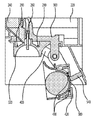
- Figure 6 is a longitudinal cross-sectional view of the ice maker when the second tray according to an embodiment of the present invention is located in the water supply position.
- FIG. 7 is a control block diagram of a refrigerator according to an embodiment of the present invention.
- Figure 8 is a flow for explaining the process of ice generation in the ice maker according to an embodiment of the present invention.
- FIG. 9 is a view for explaining a height reference according to the relative position of the transparent ice heater with respect to the ice-making cell.
- FIG. 10 is a view for explaining the output of the transparent ice heater per unit height of water in the ice-making cell.
- 11 is a view showing a state in which the water supply is completed in the water supply position.
- FIG. 12 is a view showing a state in which ice is generated at an ice-making position.
- FIG. 13 is a view showing a state separated from the second tray and the first tray in the ice-making process.
- FIG. 14 is a view showing a state in which the second tray is moved to the ice position in the ice-making process.
- 15 is a flow chart for explaining a control method of a refrigerator when door opening and closing is detected in an ice-making process.
- FIG. 16 is a view showing a change in output of the transparent ice heater for each unit height of water and a temperature change detected by the second temperature sensor in the ice making process.
- first, second, A, B, (a), and (b) may be used. These terms are only for distinguishing the component from other components, and the nature, order, or order of the component is not limited by the term.
- FIG. 1 is a view showing a refrigerator according to an embodiment of the present invention.
- a refrigerator may include a cabinet 14 including a storage compartment and a door for opening and closing the storage compartment.
- the storage compartment may include a refrigerating compartment 18 and a freezing compartment 32.
- the refrigerator compartment 14 is disposed on the upper side, and the freezer compartment 32 is disposed on the lower side, so that each storage compartment can be individually opened and closed by each door.
- a freezer compartment is arranged on the upper side and a refrigerator compartment is arranged on the lower side.
- a freezer compartment is disposed on one side of both sides, and a refrigerator compartment is disposed on the other side.
- an upper space and a lower space may be distinguished from each other, and a drawer 40 capable of drawing in and out from the lower space may be provided in the lower space.
- the door may include a plurality of doors 10, 20, and 30 that open and close the refrigerator compartment 18 and the freezer compartment 32.
- the plurality of doors (10, 20, 30) may include some or all of the doors (10, 20) for opening and closing the storage chamber in a rotating manner and the doors (30) for opening and closing the storage chamber in a sliding manner.
- the freezer 32 may be provided to be separated into two spaces, even if it can be opened and closed by one door 30.
- the freezing chamber 32 may be referred to as a first storage chamber, and the refrigerating chamber 18 may be referred to as a second storage chamber.
- An ice maker 200 capable of manufacturing ice may be provided in the freezer 32.
- the ice maker 200 may be located in an upper space of the freezer compartment 32, for example.
- An ice bin 600 in which ice produced by the ice maker 200 is dropped and stored may be provided below the ice maker 200.
- the user can take out the ice bin 600 from the freezing chamber 32 and use the ice stored in the ice bin 600.
- the ice bin 600 may be mounted on an upper side of a horizontal wall that divides an upper space and a lower space of the freezer compartment 32.
- the cabinet 14 is provided with a duct for supplying cold air to the ice maker 200.
- the duct guides cold air exchanged with the refrigerant flowing through the evaporator to the ice maker 200.
- the duct is disposed at the rear of the cabinet 14 to discharge cold air toward the front of the cabinet 14.
- the ice maker 200 may be located in front of the duct.
- the outlet of the duct may be provided on one or more of the rear side wall and the upper side wall of the freezer compartment 32.
- the ice maker 200 is provided in the freezer 32, but the space in which the ice maker 200 can be located is not limited to the freezer 32, and as long as it can receive cold air, The ice maker 200 may be located in the space.
- FIG. 2 is a perspective view showing an ice maker according to an embodiment of the present invention
- FIG. 3 is a perspective view of an ice maker with a bracket removed in FIG. 2
- FIG. 4 is an exploded perspective view of an ice maker according to an embodiment of the present invention to be
- 5 is a cross-sectional view taken along line A-A of FIG. 3 for showing a second temperature sensor installed in an ice maker according to an embodiment of the present invention.
- FIG. 6 is a longitudinal cross-sectional view of an ice maker when the second tray according to an embodiment of the present invention is located at a water supply position.
- each component of the ice maker 200 is provided inside or outside the bracket 220, so that the ice maker 200 may constitute one assembly.
- the bracket 220 may be installed, for example, on an upper wall of the freezer compartment 32.
- a water supply unit 240 may be installed on an upper side of the inner side of the bracket 220.
- the water supply unit 240 is provided with openings on the upper and lower sides, respectively, to guide water supplied to the upper side of the water supply unit 240 to the lower side of the water supply unit 240.
- the upper opening of the water supply unit 240 is larger than the lower opening, and the discharge range of water guided downward through the water supply unit 240 may be limited.
- a water supply pipe through which water is supplied may be installed above the water supply part 240. Water supplied to the water supply unit 240 may be moved downward.
- the water supply unit 240 may prevent water from being discharged from the water supply pipe from falling at a high position, thereby preventing water from splashing. Since the water supply part 240 is disposed below the water supply pipe, water is not guided to the water supply part 240 but is guided downward, and the amount of water splashed can be reduced even if it is moved downward by the lowered height.
- the ice maker 200 may include an ice-making cell 320a, which is a space in which water is phase-changed into ice by cold air.
- the ice maker 200 includes a first tray 320 forming at least a part of a wall for providing the ice making cells 320a and at least another part of a wall for providing the ice making cells 320a.
- a second tray 380 may be included.
- the ice-making cell 320a may include a first cell 320b and a second cell 320c.
- the first tray 320 may define the first cell 320b
- the second tray 380 may define the second cell 320c.
- the second tray 380 may be disposed to be movable relative to the first tray 320.
- the second tray 380 may move linearly or rotate. Hereinafter, it will be described, for example, that the second tray 380 rotates.
- the second tray 380 may move relative to the first tray 320, so that the first tray 320 and the second tray 380 may contact each other.
- the complete ice making cell 320a may be defined.
- the second tray 380 may move with respect to the first tray 320 during the ice-making process, so that the second tray 380 may be spaced apart from the first tray 320.
- the first tray 320 and the second tray 380 may be arranged in the vertical direction in the state in which the ice-making cells 320a are formed. Therefore, the first tray 320 may be referred to as an upper tray, and the second tray 380 may be referred to as a lower tray.
- a plurality of ice-making cells 320a may be defined by the first tray 320 and the second tray 380. In FIG. 4, for example, three ice cells 320a are formed.
- ice having the same or similar shape to the ice making cell 320a may be generated.
- the ice-making cell 320a may be formed in a spherical shape or a shape similar to a spherical shape.
- the first cell 320b may be formed in a hemisphere shape or a hemisphere-like shape.
- the second cell 320c may be formed in a hemisphere shape or a hemisphere-like shape.
- the ice-making cell 320a may be formed in a rectangular parallelepiped shape or a polygonal shape.
- the ice maker 200 may further include a first tray case 300 coupled with the first tray 320.
- the first tray case 300 may be coupled to the upper side of the first tray 320.
- the first tray case 300 may be made of a separate article from the bracket 220 and coupled to the bracket 220 or integrally formed with the bracket 220.
- the ice maker 200 may further include a first heater case 280.
- An ice heater 290 may be installed in the first heater case 280.
- the heater case 280 may be formed integrally with the first tray case 300 or may be formed separately.
- the ice heater 290 may be disposed at a position adjacent to the first tray 320.
- the ice heater 290 may be, for example, a wire type heater.
- the heater for ice 290 may be installed to contact the first tray 320 or may be disposed at a position spaced apart from the first tray 320. In any case, the heater for ice 290 may supply heat to the first tray 320, and heat supplied to the first tray 320 may be transferred to the ice making cell 320a.
- the ice maker 200 may further include a first tray cover 340 positioned below the first tray 320.
- the first tray cover 340 has an opening formed to correspond to the shape of the ice-making cell 320a of the first tray 320, and thus may be coupled to the lower side of the first tray 320.
- the first tray case 300 may be provided with a guide slot 302 in which an upper side is inclined and a lower side is vertically extended.
- the guide slot 302 may be provided on a member extending upwardly of the first tray case 300.
- a guide protrusion 266 of the first pusher 260 to be described later may be inserted into the guide slot 302. Accordingly, the guide protrusion 266 may be guided along the guide slot 302.
- the first pusher 260 may include at least one extension 264.
- the first pusher 260 may include an extension 264 provided in the same number as the number of ice making cells 320a, but is not limited thereto.
- the extension part 264 may push ice located in the ice-making cell 320a during the ice-making process.
- the extension part 264 may penetrate the first tray case 300 and be inserted into the ice-making cell 320a. Therefore, the first tray case 300 may be provided with a hole 304 through which a portion of the first pusher 260 penetrates.
- the guide protrusion 266 of the first pusher 260 may be coupled to the pusher link 500. At this time, the guide protrusion 266 may be coupled to the pusher link 500 so as to be rotatable. Accordingly, when the pusher link 500 moves, the first pusher 260 may also move along the guide slot 302.
- the ice maker 200 may further include a second tray case 400 coupled with the second tray 380.
- the second tray case 400 may support the second tray 380 under the second tray 380.
- at least a portion of the wall forming the second cell 320c of the second tray 380 may be supported by the second tray case 400.
- a spring 402 may be connected to one side of the second tray case 400.
- the spring 402 may provide elastic force to the second tray case 400 so that the second tray 380 can maintain a state in contact with the first tray 320.
- the ice maker 200 may further include a second tray cover 360.
- the second tray 380 may include a circumferential wall 382 surrounding a portion of the first tray 320 in contact with the first tray 320.
- the second tray cover 360 may wrap the circumferential wall 382.
- the ice maker 200 may further include a second heater case 420.
- a transparent ice heater 430 may be installed in the second heater case 420.
- the transparent ice heater 430 will be described in detail.
- the control unit 800 of the present exemplary embodiment may supply heat to the ice making cell 320a by the transparent ice heater 430 in at least a portion of cold air being supplied to the ice making cell 320a so that transparent ice can be generated. Can be controlled.
- the ice maker By the heat of the transparent ice heater 430, by delaying the speed of ice generation so that bubbles dissolved in the water inside the ice-making cell 320a can move toward the liquid water in the ice-producing portion, the ice maker ( At 200), transparent ice may be generated. That is, air bubbles dissolved in water may be induced to escape to the outside of the ice-making cell 320a or be collected to a certain position in the ice-making cell 320a.
- the cold air supply means 900 which will be described later, supplies cold air to the ice-making cell 320a, when the speed at which ice is generated is fast, bubbles dissolved in water inside the ice-making cell 320a are generated at the portion where ice is generated.
- the transparency of ice formed by freezing without moving toward liquid water may be low.
- the cold air supply means 900 supplies cold air to the ice making cell 320a, if the speed at which ice is generated is slow, the problem may be solved and the transparency of ice generated may be increased, but it takes a long time to make ice. Problems may arise.
- the transparent ice heater 430 of the ice-making cell 320a is able to locally supply heat to the ice-making cell 320a so as to reduce the delay of the ice-making time and increase the transparency of the generated ice. It can be arranged on one side.
- the transparent ice heater 430 when the transparent ice heater 430 is disposed on one side of the ice-making cell 320a, it is possible to reduce that heat of the transparent ice heater 430 is easily transferred to the other side of the ice-making cell 320a. So, at least one of the first tray 320 and the second tray 380 may be made of a material having a lower thermal conductivity than metal.
- At least one of the first tray 320 and the second tray 380 may be a resin including plastic so that ice attached to the trays 320 and 380 is well separated during the ice-making process.
- At least one of the first tray 320 and the second tray 380 may be made of flexible or flexible material so that the tray deformed by the pushers 260 and 540 during the ice-making process can be easily restored to its original form.
- the transparent ice heater 430 may be disposed at a position adjacent to the second tray 380.
- the transparent ice heater 430 may be, for example, a wire type heater.
- the transparent ice heater 430 may be installed to contact the second tray 380 or may be disposed at a position spaced apart from the second tray 380.
- the second heater case 420 is not provided separately, and it is also possible that the two-heating heater 430 is installed in the second tray case 400.
- the transparent ice heater 430 may supply heat to the second tray 380, and heat supplied to the second tray 380 may be transferred to the ice making cell 320a.
- the ice maker 200 may further include a driving unit 480 providing driving force.
- the second tray 380 may move relative to the first tray 320 by receiving the driving force of the driving unit 480.
- a through hole 282 may be formed in the extension portion 281 extending downward on one side of the first tray case 300.
- a through hole 404 may be formed in the extension part 403 extending on one side of the second tray case 400.
- the ice maker 200 may further include a shaft 440 penetrating the through holes 282 and 404 together.
- Rotating arms 460 may be provided at both ends of the shaft 440, respectively.
- the shaft 440 may be rotated by receiving rotational force from the driving unit 480.
- One end of the rotating arm 460 is connected to one end of the spring 402, so that when the spring 402 is tensioned, the position of the rotating arm 460 may be moved to an initial value by a restoring force.
- the driving unit 480 may include a motor and a plurality of gears.
- a full ice sensing lever 520 may be connected to the driving unit 480.
- the full ice sensing lever 520 may be rotated by the rotational force provided by the driving unit 480.
- the full ice sensing lever 520 may have an overall “U” shape.
- the full ice sensing lever 520 includes a first portion 521 and a pair of second portions 522 extending in directions crossing the first portion 521 at both ends of the first portion 521. ). Any one of the pair of second portions 522 may be coupled to the driving unit 480 and the other may be coupled to the bracket 220 or the first tray case 300.
- the full ice sensing lever 520 may sense ice stored in the ice bin 600 while being rotated.
- the driving unit 480 may further include a cam rotated by receiving rotational power of the motor.
- the ice maker 200 may further include a sensor that detects the rotation of the cam.
- the cam is provided with a magnet
- the sensor may be a hall sensor for sensing the magnet of the magnet during the rotation of the cam.
- the sensor may output first and second signals that are different outputs.
- One of the first signal and the second signal may be a high signal, and the other may be a low signal.
- the control unit 800 to be described later may grasp the position of the second tray 380 based on the type and pattern of the signal output from the sensor. That is, since the second tray 380 and the cam are rotated by the motor, the position of the second tray 380 may be indirectly determined based on a detection signal of a magnet provided in the cam.
- the water supply position and the ice making position may be classified and determined based on a signal output from the sensor.
- the ice maker 200 may further include a second pusher 540.
- the second pusher 540 may be installed on the bracket 220.
- the second pusher 540 may include at least one extension 544.
- the second pusher 540 may include an extension portion 544 provided in the same number as the number of ice-making cells 320a, but is not limited thereto.
- the extension 544 may push ice located in the ice making cell 320a.
- the extension part 544 may be in contact with the second tray 380 that penetrates through the second tray case 400 to form the ice-making cell 320a, and the second tray ( 380) can be pressurized. Therefore, a hole 422 through which a part of the second pusher 540 penetrates may be provided in the second tray case 400.
- the first tray case 300 is rotatably coupled to each other with respect to the second tray case 400 and the shaft 440, and may be arranged to change an angle around the shaft 440.
- the second tray 380 may be formed of a non-metal material.
- the shape when the second tray 380 is pressed by the second pusher 540, the shape may be formed of a flexible material or ductile material that can be deformed.
- the second tray 380 may be formed of, for example, silicone material.
- the pressing force of the second pusher 540 may be transferred to ice. Ice and the second tray 380 may be separated by the pressing force of the second pusher 540.
- the second tray 380 is formed of a non-metal material and a flexible or ductile material, bonding force or adhesion between ice and the second tray 380 may be reduced, so that ice can be easily separated from the second tray 380. have.
- the second tray 380 when the second tray 380 is formed of a non-metal material and a flexible or flexible material, after the shape of the second tray 380 is modified by the second pusher 540, the second pusher 540 When the pressing force of) is removed, the second tray 380 can be easily restored to its original shape.
- the first tray 320 is formed of a metal material.
- the ice maker 200 of the present embodiment may include at least one of the heater 290 for ice and the first pusher 260. You can.
- the first tray 320 may be formed of a non-metal material.
- the ice maker 200 may include only one of the heater 290 for ice and the first pusher 260.
- the ice maker 200 may not include the ice heater 290 and the first pusher 260.
- the first tray 320 may be formed of, for example, silicone material.
- the first tray 320 and the second tray 380 may be formed of the same material.
- the sealing performance is maintained at the contact portion between the first tray 320 and the second tray 380,
- the hardness of the first tray 320 and the hardness of the second tray 380 may be different.
- the second tray 380 since the second tray 380 is pressed and deformed by the second pusher 540, the second tray 380 is easy to change the shape of the second tray 380.
- the hardness of may be lower than the hardness of the first tray 320.
- the ice maker 200 may further include a second temperature sensor (or tray temperature sensor) 700 for sensing the temperature of the ice maker cell 320a.
- the second temperature sensor 700 may detect the temperature of water or the temperature of ice in the ice-making cell 320a.
- the second temperature sensor 700 is disposed adjacent to the first tray 320 to sense the temperature of the first tray 320, thereby indirectly controlling the temperature of water or ice in the ice-making cell 320a. Can be detected.
- the temperature of ice or the temperature of water in the ice making cell 320a may be referred to as an internal temperature of the ice making cell 320a.
- the second temperature sensor 700 may be installed in the first tray case 300. In this case, the second temperature sensor 700 may contact the first tray 320 or may be spaced apart from the first tray 320 by a predetermined distance. Alternatively, the second temperature sensor 700 may be installed on the first tray 320 to contact the first tray 320.
- the second temperature sensor 700 when the second temperature sensor 700 is disposed to penetrate the first tray 320, it is possible to directly detect the temperature of water or ice in the ice-making cell 320a.
- a part of the heater for ice 290 may be positioned higher than the second temperature sensor 700, and may be spaced apart from the second temperature sensor 700.
- the wire 701 connected to the second temperature sensor 700 may be guided above the first tray case 300.
- the ice maker 200 of the present embodiment may be designed such that the position of the second tray 380 is different from the water supply position and the ice making position.
- the second tray 380 includes a second cell wall 381 defining a second cell 320c among the ice making cells 320a and an outer border of the second cell wall 381. It may include an extended circumferential wall 382.
- the second cell wall 381 may include an upper surface 381a.
- the upper surface 381a of the second cell wall 381 may be referred to as the upper surface 381a of the second tray 380.
- the upper surface 381a of the second cell wall 381 may be positioned lower than the upper end of the circumferential wall 381.
- the first tray 320 may include a first cell wall 321a defining a first cell 320b among the ice making cells 320a.
- the first cell wall 321a may include a straight portion 321b and a curved portion 321c.
- the curved portion 321c may be formed in an arc shape having a center of the shaft 440 as a radius of curvature. Therefore, the circumferential wall 381 may also include a straight portion and a curved portion corresponding to the straight portion 321b and the curved portion 321c.
- the first cell wall 321a may include a lower surface 321d.
- the lower surface 321b of the first cell wall 321a may be referred to as the lower surface 321b of the first tray 320.
- the lower surface 321d of the first cell wall 321a may contact the upper surface 381a of the second cell wall 381a.
- At least a portion of the lower surface 321d of the first cell wall 321a and the upper surface 381a of the second cell wall 381 may be spaced apart.
- the lower surface 321d of the first cell wall 321a and the entire upper surface 381a of the second cell wall 381 are spaced apart from each other.
- the upper surface 381a of the second cell wall 381 may be inclined to form a predetermined angle with the lower surface 321d of the first cell wall 321a.
- the bottom surface 321d of the first cell wall 321a in the water supply position may be substantially horizontal, and the top surface 381a of the second cell wall 381 is the first cell wall ( It may be disposed to be inclined with respect to the lower surface (321d) of the first cell wall (321a) under the 321a).
- the circumferential wall 382 may surround the first cell wall 321a.
- the upper end of the circumferential wall 382 may be positioned higher than the lower surface 321d of the first cell wall 321a.
- the upper surface 381a of the second cell wall 381 may contact at least a portion of the lower surface 321d of the first cell wall 321a.
- the angle between the upper surface 381a of the second tray 380 and the lower surface 321d of the first tray 320 in the ice-making position is the upper surface 382a and the second surface of the second tray 380 in the water supply position. 1 is smaller than the angle formed by the lower surface 321d of the tray 320.
- the upper surface 381a of the second cell wall 381 may contact all of the lower surface 321d of the first cell wall 321a.
- the upper surface 381a of the second cell wall 381 and the lower surface 321d of the first cell wall 321a may be disposed to be substantially horizontal.
- the reason the water supply position of the second tray 380 is different from the ice-making position is that when the ice-maker 200 includes a plurality of ice-making cells 320a, communication between each ice-making cell 320a is performed.
- the purpose is to ensure that water is not evenly distributed to the first tray 320 and / or the second tray 380, but the water is uniformly distributed to the plurality of ice cells 320a.
- the ice maker 200 when the ice maker 200 includes the plurality of ice cells 320a, when water passages are formed in the first tray 320 and / or the second tray 380, the ice maker 200 The water supplied to is distributed to a plurality of ice-making cells 320a along the water passage.
- water dropped into the second tray 380 is the second tray. It may be uniformly distributed to the plurality of second cells (320c) of (380).
- the first tray 320 may include a communication hole 321e.
- the first tray 320 may include one communication hole 321e.
- the first tray 320 may include a plurality of communication holes 321e.
- the water supply part 240 may supply water to one communication hole 321e among the plurality of communication holes 321e. In this case, water supplied through the one communication hole 321e is dropped to the second tray 380 after passing through the first tray 320.
- water may be dropped into any one of the plurality of second cells 320c of the second tray 380, whichever is the second cell 320c. Water supplied to one second cell 320c overflows from the second cell 320c.
- the upper surface 381a of the second tray 380 is spaced apart from the lower surface 321d of the first tray 320, water overflowed from any one of the second cells 320c is the first agent. 2 It moves to another adjacent second cell 320c along the upper surface 381a of the tray 380. Therefore, water may be filled in the plurality of second cells 320c of the second tray 380.
- water upon completion of water supply is located only in a space between the first tray 320 and the second tray 380, or the first tray 320 A space between the second trays 380 and the first tray 320 may also be located (see FIG. 11).
- At least one of the cooling power of the cold air supply means 900 and the heating amount of the transparent ice heater 430 is determined according to the mass per unit height of water in the ice making cell 320a.
- one or more of the cooling power of the cold air supply means 900 and the heating amount of the transparent ice heater 430 in the portion where the water passage is formed is controlled to be rapidly changed several times or more.
- the present invention may require a technique related to the above-described ice making location to generate transparent ice.
- FIG. 7 is a control block diagram of a refrigerator according to an embodiment of the present invention.
- the refrigerator of the present embodiment may further include a cold air supply means 900 for supplying cold air to the freezer 32 (or ice making cell).
- the cold air supply means 900 may supply cold air to the freezing chamber 32 using a refrigerant cycle.
- the cold air supply means 900 may include a compressor to compress the refrigerant. Depending on the output (or frequency) of the compressor, the temperature of the cold air supplied to the freezing chamber 32 may be changed.
- the cold air supply means 900 may include a fan for blowing air with an evaporator. The amount of cold air supplied to the freezer compartment 32 may vary according to the output (or rotational speed) of the fan.
- the cold air supply means 900 may include a refrigerant valve that controls the amount of refrigerant flowing through the refrigerant cycle. The amount of refrigerant flowing through the refrigerant cycle is varied by adjusting the opening degree by the refrigerant valve, and accordingly, the temperature of the cold air supplied to the freezing chamber 32 may be changed.
- the cold air supply means 900 may include one or more of the compressor, fan, and refrigerant valve.
- the refrigerator of the present embodiment may further include a control unit 800 that controls the cold air supply means 900.
- the refrigerator may further include a water supply valve 242 for controlling the amount of water supplied through the water supply unit 240.
- the refrigerator may further include a door opening / closing detection unit 930 for detecting opening / closing of the door of the storage compartment (for example, the freezer compartment 32) in which the ice maker 200 is installed.
- the control unit 800 may control some or all of the ice heater 290, the transparent ice heater 430, the driving unit 480, the cold air supply means 900, and the water supply valve 242. have.
- the control unit 800 may cool the air based on the temperature detected by the first temperature sensor 33. It is possible to determine whether the cooling means of the supply means 900 is variable.
- the controller 800 determines whether the output of the transparent ice heater 430 is variable based on the temperature detected by the second temperature sensor 700. Can decide.
- the output of the ice heater 290 and the transparent ice heater may be different.
- the output terminal of the ice heater 290 and the output terminal of the transparent ice heater 430 may be formed in different forms. , It is possible to prevent incorrect connection of the two output terminals.
- the output of the ice heater 290 may be set larger than the output of the transparent ice heater 430. Accordingly, ice may be quickly separated from the first tray 320 by the ice heater 290.
- the transparent ice heater 430 when the heater 290 for ice is not provided, the transparent ice heater 430 is disposed at a position adjacent to the second tray 380 described above, or the first tray 320 and It can be placed in an adjacent position.
- the refrigerator may further include a first temperature sensor 33 (or internal temperature sensor) that senses the temperature of the freezer 32.
- the control unit 800 may control the cold air supply means 900 based on the temperature sensed by the first temperature sensor 33.
- control unit 800 may determine whether ice-making is completed based on the temperature detected by the second temperature sensor 700.
- FIG. 8 is a flowchart illustrating a process in which ice is generated in an ice maker according to an embodiment of the present invention.
- FIG. 9 is a view for explaining the height reference according to the relative position of the transparent ice heater with respect to the ice-making cell
- FIG. 10 is a view for explaining the output of the transparent ice heater per unit height of water in the ice-making cell.
- FIG. 11 is a view showing a state in which water supply is completed at a water supply position
- FIG. 12 is a view showing a state in which ice is generated at an ice-making position
- FIG. 13 is a state in which the second tray is separated from the first tray in the ice-making process
- 14 is a view showing a state in which the second tray is moved to the ice position in the ice-making process.
- the controller 800 moves the second tray 380 to a water supply position (S1).
- a direction in which the second tray 380 moves from the ice-making position of FIG. 12 to the ice-making position of FIG. 14 may be referred to as forward movement (or forward rotation).
- the direction of movement from the ice position of FIG. 14 to the water supply position of FIG. 6 may be referred to as reverse movement (or reverse rotation).
- the movement of the water supply position of the second tray 380 is sensed by a sensor, and when it is sensed that the second tray 380 has been moved to the water supply position, the control unit 800 stops the driving unit 480.
- Water supply is started while the second tray 380 is moved to the water supply position (S2).
- the controller 800 turns on the water supply valve 242, and when it is determined that a predetermined amount of water is supplied, the control unit 800 may turn off the water supply valve 242. For example, in the process of supplying water, when a pulse is output from a flow sensor (not shown) and the output pulse reaches a reference pulse, it may be determined that water is supplied as much as a set amount.
- control unit 800 controls the driving unit 480 so that the second tray 380 moves to the ice-making position (S3).
- the control unit 800 may control the driving unit 480 such that the second tray 380 moves in the reverse direction from the water supply position.
- the upper surface 381a of the second tray 380 is close to the lower surface 321e of the first tray 320. Then, water between the upper surface 381a of the second tray 380 and the lower surface 321e of the first tray 320 is divided and distributed inside each of the plurality of second cells 320c. When the upper surface 381a of the second tray 380 and the lower surface 321e of the first tray 320 are completely in close contact, water is filled in the first cell 320b.
- the movement of the ice-making position of the second tray 380 is sensed by a sensor, and when it is sensed that the second tray 380 is moved to the ice-making position, the control unit 800 stops the driving unit 480.
- De-icing is started while the second tray 380 is moved to the de-icing position (S4).
- the de-icing position For example, when the second tray 380 reaches the ice-making position, ice-making may start. Alternatively, when the second tray 380 reaches the ice-making position and the water supply time elapses, the ice-making may start.
- control unit 800 may control the cold air supply means 900 such that cold air is supplied to the ice-making cell 320a.
- control unit 800 may control the transparent ice heater 430 to be turned on in at least a portion of the cold air supply means 900 supplying cold air to the ice-making cell 320a. have.
- the transparent ice heater 430 When the transparent ice heater 430 is turned on, the heat of the transparent ice heater 430 is transferred to the ice-making cell 320a, so the rate of ice generation in the ice-making cell 320a may be delayed.
- the rate of ice generation so that the bubbles dissolved in the water inside the ice-making cell 320a can move toward the liquid water in the portion where ice is generated.
- transparent ice may be generated in the ice maker 200.
- control unit 800 may determine whether or not the ON condition of the transparent ice heater 430 is satisfied (S5).
- the ice-making is not started and the transparent ice heater 430 is not turned on immediately, but the transparent ice heater 430 may be turned on only when the ON condition of the transparent ice heater 430 is satisfied (S6).
- the water supplied to the ice-making cell 320a may be water at room temperature or water at a temperature lower than room temperature.
- the temperature of the water thus supplied is higher than the freezing point of water. Therefore, after the watering, the temperature of the water is lowered by cold air, and when it reaches the freezing point of the water, the water changes to ice.
- the transparent ice heater 430 may not be turned on until water is phase-changed to ice.
- the transparent ice heater 430 If the transparent ice heater 430 is turned on before the temperature of the water supplied to the ice-making cell 320a reaches the freezing point, the speed at which the water temperature reaches the freezing point is slowed by the heat of the transparent ice heater 430 As a result, the onset of ice formation is delayed.
- the transparency of ice may vary depending on the presence or absence of air bubbles in the ice-producing portion after ice is generated.
- the ice transparency may be It can be seen that the transparent ice heater 430 operates.
- the transparent ice heater 430 when the transparent ice heater 430 is turned on after the ON condition of the transparent ice heater 430 is satisfied, power is consumed according to unnecessary operation of the transparent ice heater 430. Can be prevented.
- the controller 800 may determine that the ON condition of the transparent ice heater 430 is satisfied when a predetermined period of time has elapsed from the set specific time point.
- the specific time point may be set to at least one of the time points before the transparent ice heater 430 is turned on.
- the specific point in time may be set to a point in time when the cold air supply means 900 starts supplying cold power for de-icing, a point in time when the second tray 380 reaches the ice-making position, a point in time when water supply is completed. .
- control unit 800 may determine that the ON condition of the transparent ice heater 430 is satisfied.
- the on reference temperature may be a temperature for determining that water is starting to freeze at the uppermost side (communication hole side) of the ice-making cell 320a.
- the temperature of ice in the ice-making cell 320a is a freezing temperature.
- the temperature of the first tray 320 may be higher than the temperature of ice in the ice-making cell 320a.
- the temperature sensed by the second temperature sensor 700 may be below zero after ice is generated in the ice-making cell 320a.
- the on-reference temperature may be set to a temperature below zero.
- the on reference temperature is the sub-zero temperature
- the ice temperature of the ice making cell 320a is the reference temperature that is on the sub-zero Will be lower. Therefore, it may be indirectly determined that ice is generated in the ice-making cell 320a.
- the transparent ice heater 430 when the second tray 380 is located under the first tray 320 and the transparent ice heater 430 is arranged to supply heat to the second tray 380 In the ice may be generated from the upper side of the ice-making cell 320a.
- the mass (or volume) per unit height of water in the ice-making cell 320a may be the same or different.
- the mass (or volume) per unit height of water in the ice making cell 320a is the same.
- the mass (or volume) per unit height of water is different.
- the mass per unit height of water when the mass per unit height of water is small, the ice production rate is fast, whereas when the mass per unit height of water is large, the ice generation rate is slow.
- the rate at which ice is generated per unit height of water is not constant, and the transparency of ice can be varied for each unit height.
- the rate of ice formation is high, bubbles may not move from the ice to the water, and ice may contain bubbles, so that the transparency may be low.
- the cold power of the cold air supply means 900 may include one or more of a variable output of the compressor, a variable output of the fan, and a variable opening degree of the refrigerant valve.
- variable amount of heating of the transparent ice heater 430 may mean varying the output of the transparent ice heater 430 or varying the duty of the transparent ice heater 430. .
- the duty of the transparent ice heater 430 means a ratio of an on time to an on time and an off time of the transparent ice heater 430 in one cycle, or an on time of the transparent ice heater 430 in one cycle. It may mean a ratio of off time to off time.
- the reference of the unit height of water in the ice-making cell 320a may vary according to the relative positions of the ice-making cell 320a and the transparent ice heater 430.
- the height of the transparent ice heater 430 may be arranged at the bottom of the ice making cell 320a.
- a line connecting the transparent ice heater 430 is a horizontal line, and a line extending in a vertical direction from the horizontal line serves as a reference for a unit height of water in the ice-making cell 320a.
- ice is generated from the top side to the bottom side of the ice-making cell 320a and grows.
- the height of the transparent ice heater 430 at the bottom of the ice-making cell 320a may be arranged to be different.
- ice is generated at a position spaced apart from the top side to the left side in the ice making cell 320a, and ice may grow to the bottom right side where the transparent ice heater 430 is located. .
- a line perpendicular to the line connecting the two points of the transparent ice heater 430 serves as a reference for the unit height of water in the ice-making cell 320a.
- the reference line in FIG. 9B is inclined at a predetermined angle from the vertical line.
- FIG. 10 shows the unit height of water and the output amount of the transparent ice heater per unit height when the transparent ice heater is disposed as shown in FIG. 9 (a).
- the mass per unit height of water in the ice-making cell 320a increases from the upper side to the lower side, becomes maximum, and decreases again. .
- water (or the ice-making cell itself) in a spherical ice-making cell 320a having a diameter of 50 mm is divided into 9 sections (A section to I section) at a height of 6 mm (unit height). At this time, it is revealed that there is no limit to the size of the unit height and the number of divided sections.
- each section to be divided is the same from the A section to the H section, and the I section has a lower height than the remaining sections.
- unit heights of all divided sections may be the same.
- the E section is the section with the largest mass per unit height of water.
- the mass per unit height of water is maximum
- the diameter of the ice making cell 320a, the horizontal cross-sectional area of the ice making cell 320a, or the circumference of the ice Contains phosphorus part.
- the ice generation rate in section E is the slowest, section A and I The fastest ice formation in the section.
- the rate of ice formation is different for each unit height, and thus the transparency of ice is different for each unit height, and in a certain section, the rate of ice generation is too fast, and thus there is a problem in that transparency is lowered, including air bubbles.
- the output of the transparent ice heater 430 is performed such that the ice generation speed is the same or similar for each unit height. Can be controlled.
- the output W5 of the transparent ice heater 430 in the E section may be set to a minimum. Since the mass of the D section is smaller than the mass of the E section, the speed of ice formation increases as the mass decreases, so it is necessary to delay the ice production rate. Therefore, the output W4 of the two-beaming heater 430 in the D period may be set higher than the output W5 of the transparent ice heater 430 in the E period.
- the output W3 of the transparent ice heater 430 in the C section may be set higher than the output W4 of the transparent ice heater 430 in the D section. You can.
- the output W2 of the transparent ice heater 430 in the B section may be set higher than the output W3 of the transparent ice heater 430 in the C section.
- the output W1 of the transparent ice heater 430 in section A may be set higher than the output W2 of the transparent ice heater 430 in section B. .
- the mass per unit height decreases as it goes from the E section to the lower side, so the output from the transparent ice heater 430 may increase as it goes from the E section to the lower side (see W6, W7, W8, W9). .
- the output of the transparent ice heater 430 may be reduced step by step from the first section to the middle section.
- the output of the transparent ice heater 430 may be minimum in the middle section, which is a section in which the mass for each unit height of water is minimum.
- the output of the transparent ice heater 430 may be gradually increased from the next section of the intermediate section.
- the transparency of ice is uniform for each unit height, and bubbles are collected in the lowermost section. Therefore, when viewed as a whole of ice, bubbles may be collected in the localized portion and the other portions may be entirely transparent.
- the output of the transparent ice heater 430 is varied according to the mass per unit height of water in the ice making cell 320a, even if the ice making cell 320a is not spherical, transparent ice is generated. can do.
- the heating amount of the transparent ice heater 430 when the mass per unit height of water is large is smaller than the heating amount of the transparent ice heater 430 when the mass per unit height of water is small.
- the heating amount of the transparent ice heater 430 may be varied to be inversely proportional to the mass of each unit height of water.
- the cooling power of the cold air supply means 900 may be increased, and when the mass per unit height is small, the cooling power of the cold air supply means 900 may be decreased.
- the cooling power of the cold air supply means 900 may be varied to be proportional to the mass per unit height of water.
- the cold power of the cold air supply means 900 may be increased step by step from the first section to the middle section.
- the cooling power of the cold air supply means 900 may be maximum in the middle section, which is a section in which the mass for each unit height of water is minimum.
- the cooling power of the cold air supply means 900 may be gradually reduced from the next section of the intermediate section.
- transparent ice may be generated.
- the cooling power of the cold air supply means 900 may be varied to be proportional to the mass per unit height of water, and the heating amount of the transparent ice heater 430 may be varied to be inversely proportional to the mass per unit height of water.
- the rate of ice generation per unit height of water is substantially It can be the same or maintained within a predetermined range.
- control unit 800 may determine whether ice-making is completed based on the temperature detected by the second temperature sensor 700 (S8). When it is determined that ice making is completed, the control unit 800 may turn off the transparent ice heater 430 (S9).
- the controller 800 may determine that ice-making is complete and turn off the transparent ice heater 430.
- the controller 800 can be started after a certain period of time has elapsed from the time when it is determined that ice-making is completed, or when the temperature sensed by the second temperature sensor 700 reaches a second reference temperature lower than the first reference temperature.
- control unit 800 When ice-making is completed, in order to ice, the control unit 800 operates one or more of the ice heater 290 and the transparent ice heater 430 (S10).
- first tray 320 and the second tray 380 may be separated from one or more surfaces (inner surfaces).
- the heat of the heater (290, 430) is transferred to the contact surface of the first tray 320 and the second tray 380, the lower surface 321d of the first tray 320 and the second tray ( It becomes a state which can be separated between the top surfaces 381a of 380).
- the controller 800 When at least one of the ice heater 290 and the transparent ice heater 430 is operated for a set time, or when the temperature detected by the second temperature sensor 700 exceeds the off reference temperature, the controller 800 The turned on heaters 290 and 430 are turned off (S10).
- the off reference temperature may be set as the temperature of the image.
- the control unit 800 operates the driving unit 480 so that the second tray 380 is moved in the forward direction (S11).
- the moving force of the second tray 380 is transmitted to the first pusher 260 by the pusher link 500. Then, the first pusher 260 descends along the guide slot 302, the extension portion 264 penetrates the communication hole 321e, and presses ice in the ice making cell 320a. do.
- ice in the ice-making process, ice may be separated from the first tray 320 before the extension 264 presses the ice. That is, ice may be separated from the surface of the first tray 320 by the heat of the heated heater. In this case, ice may be moved together with the second tray 380 while being supported by the second tray 380.
- ice may not be separated from the surface of the first tray 320.
- ice may be separated from the second tray 380 in a state in which the ice is in close contact with the first tray 320.
- the extension portion 264 passing through the communication hole 320e presses the ice in close contact with the first tray 320, so that the ice is It may be separated from the first tray 320.
- Ice separated from the first tray 320 may be supported by the second tray 380 again.
- the ice When the ice is moved together with the second tray 380 in a state supported by the second tray 380, even if no external force is applied to the second tray 380, the ice is moved by the second weight due to its own weight. It can be separated from the tray 250.
- the second tray 380 by the second pusher 540 as shown in FIG. When is pressed, ice may be separated from the second tray 380 and dropped downward.
- the second tray 380 comes into contact with the extension 544 of the second pusher 540.
- the extension portion 544 presses the second tray 380 so that the second tray 380 is deformed, and the extension portion ( The pressing force of 544) is transferred to the ice so that the ice can be separated from the surface of the second tray 380. Ice separated from the surface of the second tray 380 may drop downward and be stored in the ice bin 600.
- the position where the second tray 380 is pressed and deformed by the second pusher 540 may be referred to as an ice location.
- the full ice sensing lever 520 when the full ice sensing lever 520 is rotated together with the second tray 380, and when the full ice sensing lever 520 is rotated, the rotation of the full ice sensing lever 520 is interfered by ice. , It may be determined that the ice bin 600 is in a full state. On the other hand, if the rotation of the full ice sensing lever 520 is not interfered with by ice while the full ice sensing lever 520 is rotated, it may be determined that the ice bin 600 is not full.
- the controller 800 controls the driving unit 480 so that the second tray 380 moves in the reverse direction (S11). Then, the second tray 380 is moved from the ice position toward the water supply position.
- the control unit 800 stops the driving unit 480 (S1).
- the modified second tray 380 may be restored to its original shape. have.
- the moving force of the second tray 380 is transmitted to the first pusher 260 by the pusher link 500 in the reverse movement process of the second tray 380, so that the first pusher 260 Rises, and the extension part 264 falls out of the ice-making cell 320a.
- the cooling power of the cold air supply means 900 may be determined in correspondence to a target temperature of the freezing chamber 32.
- the cold air generated by the cold air supply means 900 may be supplied to the freezing chamber 32.
- Water of the ice-making cell 320a may be phase-changed to ice by cold air supplied to the freezing chamber 32 and heat transfer of water of the ice-making cell 320a.
- the amount of heating of the transparent ice heater 430 per unit height of water may be determined in consideration of a predetermined cooling power of the cold air supply means 900.
- the heating amount (or output) of the transparent ice heater 430 determined in consideration of the predetermined cooling power of the cold air supply means 900 is referred to as a reference heating amount (or reference output).
- the standard amount of heating per unit height of water is different.
- the heat transfer amount of cold and water is increased, for example, when the cooling power of the cold air supply means 900 is increased, or the air having a temperature lower than the temperature of the cold air in the freezing chamber 32 to the freezing chamber 32 May be supplied.
- the heat transfer amount of cold air and water is reduced, for example, when the cooling power of the cold air supply means 900 is reduced, or the door is opened and the freezing chamber 32 is higher than the temperature of the cold air in the freezing chamber 32
- the air is supplied, or when food having a temperature higher than the temperature of the cold air in the freezer 32 is input to the freezer 32, or when a defrost heater (not shown) for defrosting the evaporator is turned on You can.
- the target temperature of the freezer 32 is lowered, the operation mode of the freezer 32 is changed from the normal mode to the rapid cooling mode, or the output of one or more of the compressor and fan is increased, or the refrigerant valve
- the cooling power of the cold air supply means 900 may be increased.
- the target temperature of the freezer compartment 32 is increased, the operation mode of the freezer compartment 32 is changed from the rapid cooling mode to the normal mode, the output of one or more of the compressor and fan is reduced, or the opening degree of the refrigerant valve When reduced, the cooling power of the cold air supply means 900 may be reduced.
- the amount of heat transfer of cold air and water is increased so that the ice-making speed can be maintained within a predetermined range lower than the ice-making speed when ice-making is performed while the transparent ice heater 430 is turned off, transparent ice
- the heating amount of the heater 430 can be controlled to increase.
- the ice-making speed when the ice-making speed is maintained within the predetermined range, the ice-making speed becomes slower than the speed at which air bubbles move in a portion where ice is generated in the ice-making cell 320a, so that air bubbles are not present in the portion where ice is generated. It does not.
- FIG. 15 is a flowchart illustrating a control method of a refrigerator when door opening and closing is detected in the ice making process
- FIG. 16 is a change in output of the transparent ice heater for each unit height of water and a temperature change detected by the second temperature sensor in the ice making process It is a drawing showing.
- FIG. 16A is a view when the door is not opened and closed in the ice making process
- FIG. 16B is a view when door opening and closing is detected in the ice making process.
- ice-making is started (S4), and ice-making may be generated when the transparent ice heater 430 is turned on in the ice-making process.
- the cold air supply means 900 may operate with a predetermined cooling power.
- the compressor may be turned on, and the fan may operate at a predetermined output.
- the door opening / closing detection unit 930 may detect opening / closing of a door (for example, a door opening / closing a freezer) (S41).
- the control unit 800 supplies the cold air based on the change in temperature detected by the first temperature sensor 33 and the second temperature sensor 700.
- the means 900 or the transparent ice heater 430 even when the door is opened and closed, the transparency of the transparent ice can be made uniform.
- control unit 800 may determine whether an increase in cooling power of the cold air supply means 900 is necessary (S42).
- the controller 800 needs to increase the cooling power of the cold air supply means 900. You can judge that.
- the first set temperature is a temperature higher than the temperature detected by the first temperature sensor 33 when the opening of the door is detected.
- the cooling power of the cold air supply means 900 may be increased (S43).
- control unit 800 may increase the heating amount of the transparent ice heater 430 in response thereto (S44).
- control unit 800 after the opening and closing of the door is detected, the temperature detected by the first temperature sensor 33 is detected by the first temperature sensor 33 before the opening and closing of the door is detected.
- the temperature is higher than the first set value, it may be determined that an increase in cooling power of the cold air supply means 900 is necessary.
- control unit 800 after the opening and closing of the door is detected, the temperature detected by the first temperature sensor 33 is detected by the first temperature sensor 33 before the opening and closing of the door is detected.
- the temperature is not higher than the first set value, it may be determined that the increase in the cooling power of the cold air supply means 900 is unnecessary.
- the temperature change of the freezer compartment 32 may be small due to a small influence of air temperature outside the refrigerator. In this case, it is possible to maintain the current cooling power without increasing the cooling power of the cold air supply means 900 (S45).
- control unit 800 may determine whether a reduction in the heating amount of the transparent ice heater 430 is necessary (S46).
- the control unit 800 determines that the heating amount of the transparent ice heater 430 needs to be reduced, and thus the transparent ice heater
- the heating amount of 430 may be reduced (S47). That is, the heating amount of the transparent ice heater 430 may be reduced than the heating amount before the door opening and closing is detected.
- the ice-making speed may be delayed by the temperature increase of the ice-making cell 320a. Since, it is possible to reduce the amount of heating of the transparent ice heater 430.
- the heating amount of the transparent ice heater 430 is maintained when the temperature of the ice-making cell 320a is increased, there is a disadvantage that the ice-making speed is significantly delayed.
- the ice-making speed of ice may be delayed by the temperature increase of the freezer 32, so the transparent ice Power consumption may be reduced by reducing the output of the heater 430.
- the amount of heating of the transparent ice heater 430 may be maintained (S48).
- the control unit 800 the temperature detected by the second temperature sensor 700 is greater than a second set value than the temperature detected by the second temperature sensor 700 before the opening and closing of the door is detected If it is increased by, it is determined that the heating amount of the transparent ice heater 430 needs to be reduced and the heating amount of the transparent ice heater 430 can be reduced (S47).
- control unit 800 after the opening and closing of the door is detected, the temperature detected by the second temperature sensor 700 is detected by the second temperature sensor 700 before the opening and closing of the door is detected If the temperature does not increase by more than the second set value, it may be determined that the heating amount of the transparent ice heater 430 is unnecessary.
- control unit 800 may maintain the heating amount of the transparent ice heater 430 if the heating amount of the transparent ice heater 430 is less than or equal to a reference value after door opening and closing is detected. On the other hand, if the heating amount of the transparent ice heater 430 is greater than a reference value after the door opening and closing is detected, the control unit 800 may reduce the heating amount of the transparent ice heater 430.
- the reference value may be, for example, the minimum heating amount of the transparent ice heater.
- the transparent ice heater 430 is controlled such that the reference output is variable for each section.
- the temperature sensed by the second temperature sensor 700 has a decreasing pattern.
- the temperature sensed by the second temperature sensor 700 may be increased.
- the control unit 800 may reduce the output of the transparent ice heater 430. Although not limited, the control unit 800 may turn off the transparent ice heater 430.
- control unit 800 determines whether the temperature detected by the second temperature sensor 700 has reached the reference temperature of the next section. Can judge.
- the control unit 800 has passed a set time or the temperature detected by the second temperature sensor 700 decreases the amount of heating.
- the heating amount variable control of the transparent ice heater 430 is normally performed (S49).
- variable amount of heating of the transparent ice heater 430 is performed during the ice-making process
- variable amount of time of heating of the transparent ice heater 430 is time or temperature sensed by the second temperature sensor 700.
- the heating amount of the transparent ice heater 430 may be changed to a reference heating amount corresponding to the next section.
- the reference temperature for changing the section in the memory is predetermined in advance, apart from the set time.
- the reference temperature of each of the plurality of sections may be determined in advance and stored in the memory.
- the reference temperature is not used in a normal ice-making process, and can be used only when determining whether a reduction in the heating amount of the transparent ice heater 430 is required after door opening and closing is detected.
- the heating amount of the transparent ice heater 430 corresponds to the next section It can be changed to the heating amount.
- the reference temperature of each of the plurality of sections may be previously determined and stored in the memory, and the heating amount of the transparent ice heater 430 may be variably controlled using the reference temperature even in a normal ice-making process.
- the second temperature sensor 700 reaches the reference temperature for starting the next section. The time it takes to get longer.
- the ice-making time when the door opening and closing is detected in the ice-making process and the heating amount of the transparent ice heater is reduced will be longer than the ice-making time when the door opening and closing is not detected in the ice-making process.
- the temperature detected by the second temperature sensor 700 is of the E section.
- the heating amount of the transparent ice heater 430 may be changed to a heating amount corresponding to the F section. Subsequently, the heating amount of the transparent ice heater 430 may be controlled to operate with a reference heating amount corresponding to the G section to the I section.
- the control unit 800 decreases the heating amount of the transparent ice heater 430 only in the current section, and when the next section starts, the next section In the control, the heating amount variable control of the transparent ice heater 430 is normally performed (S49).
- the present exemplary embodiment after detecting the opening and closing of the door, by controlling the heating amount of the cold air supply means and the transparent ice heater based on the temperature detected by the first temperature sensor and the temperature detected by the second temperature sensor, Not only can the temperature be maintained at the target temperature, it is also possible to prevent excessive heat from being supplied to the ice-making cell.
- control method of the refrigerator of FIG. 16 has been described as including steps S42 to S48, but unlike this, it is also possible that the control method of the refrigerator does not include steps S42 to S45. That is, when the opening and closing of the door is detected, step S46 may be performed immediately.
- step S46 is performed first, and then step S42 is performed.
- the "driving" of the refrigerator determines whether a start condition of the operation is satisfied, determines whether a predetermined operation is performed when the start condition is satisfied, and whether a stop condition of the operation is satisfied. It can be defined as including four operation steps of the step and the operation is terminated when the termination condition is satisfied.
- the "operation" of the refrigerator may be defined by dividing it into a general operation for cooling the refrigerator storage room and a special operation that starts when a specific condition is satisfied.
- the control unit of the present invention can be controlled such that when the normal operation and the special operation collide, the special operation takes precedence and the normal operation is stopped.
- the controller may control the normal operation to resume.
- the "collision" of the driving is when the starting condition of the driving A and the starting condition of the driving B are satisfied at the same time, when the starting condition of the driving A is satisfied and the starting condition of the driving B is satisfied while the driving A is being performed. And, it may be defined as a case in which the start condition of operation A is satisfied while the start condition of operation B is satisfied and the operation is being performed.
- the control unit 800 performs a cold air supply means to perform a normal ice-making process ( 900) is defined as an operation that controls at least one of the cooling power of the cooling power or the heating amount of the transparent ice heater 430 to be variable.
- the first transparent ice operation may include the control unit 800 controlling the cold air supply means 900 to supply cold air to the ice cells 320a.
- the control unit 800 supplies the cold air so that bubbles dissolved in water inside the ice-making cell 320a move toward liquid water in a portion where ice is generated, thereby generating transparent ice.
- the means 900 may include controlling the transparent ice heater 430 to be turned on in at least a portion of the cold air supply.
- the control unit 800 may control the turned-on transparent ice heater 430 to be variable to a predetermined reference heating amount in each of a plurality of divided sections.
- the pre-divided plurality of sections are divided based on the unit height of water to be defrosted, and when the second tray 380 is moved to the de-icing position and divided based on the elapsed time, and the second tray After moving the 380 to the ice-making position, at least one of cases classified based on the temperature sensed by the second temperature sensor 700 may be included.
- the special operation for generating transparent ice refers to the transparent ice operation for the door load response and the defrost operation for performing the ice making process when the start condition of the door load response operation is satisfied.
- the start condition it may include transparent ice driving for defrosting to perform an ice-making process.
- the control unit 800 removes heat load input to the storage room by opening and closing the door. It may include the step of increasing the cooling power of the cold air supply means (900).
- Control the heating amount of the transparent ice heater 430 to be smaller than the heating amount during the first transparent ice operation in order to reduce the temperature and maintain the ice making speed within a predetermined range to uniformly maintain the transparency of ice. It may include steps.
- the start condition of the door load response operation for the cold air supply means 900 and the start condition of the door load response operation for the transparent ice heater 430 may be different.
- the end condition of the door load response operation for the cold air supply means 900 and the end condition of the door load response operation for the transparent ice heater 430 may be different.
- the cold air supply variable of the cold air supply means 900 is necessary, and the cold power variable is necessary. It may mean the case where it is judged to be.
- the first set time has elapsed since the opening of the door was detected, and the opening and closing of the door was detected. Includes at least one of a case in which the temperature detected by the temperature sensor is greater than or equal to the first set temperature and higher than the temperature detected by the first temperature sensor 33 after the opening and closing of the door is detected can do.
- the heating amount of the transparent ice heater 430 needs to be varied, and the heating amount is variable. This may mean a case where it is deemed necessary.
- the second set time has elapsed since the opening of the door was detected, and the opening and closing of the door was detected. 2
- the temperature detected by the temperature sensor is greater than or equal to the second set temperature, and when the opening and closing of the door is detected, when the temperature is higher than or equal to the second set value by the second temperature sensor,
- the amount of change in the temperature detected by the second temperature sensor per unit time after detection is greater than 0, and when the current heating amount of the transparent ice heater 430 is greater than a reference value after the opening and closing of the door is detected, and the cold air It may include at least one of the case where the start condition of the door load response operation for the supply means 900 is satisfied.
- the control unit 800 heats the transparent ice heater 430 when the amount of temperature change detected by the second temperature sensor 700 per unit time is greater than zero. The amount can be reduced. On the other hand, when the change amount of the temperature is not greater than 0, the heating amount of the transparent ice heater 430 may be maintained.
- the control unit 800 is the first transparent after both the end condition of the door load response operation for the cold air supply means 900 and the end condition of the door load response operation for the transparent ice heater 430 are satisfied. It can be controlled to resume the ice operation.
- the first set temperature and the first set temperature may be the same or different.
- the second set temperature and the B set temperature may be the same or different.
- the first set value and the first set value may be the same or different.
- the second set value and the B set value may be the same or different.
- the second set value may be set differently according to a plurality of sections. At least one of the second set values may be greater than the first set value.
Abstract
Description
Claims (21)
- 음식물이 보관되는 저장실;상기 저장실의 온도를 감지하기 위한 제 1 온도 센서;상기 저장실을 개폐하는 도어;상기 저장실로 냉기를 공급하기 위한 냉기공급수단;물이 상기 냉기에 의해서 얼음으로 상변화되는 공간인 제빙셀을 형성하는 트레이;상기 제빙셀의 물 또는 얼음의 온도를 감지하기 위한 제 2 온도 센서;상기 트레이로 열을 제공하기 위한 히터; 및상기 히터를 제어부를 포함하고,상기 제어부는, 제빙 과정에서 상기 도어의 개폐가 감지된 후,상기 제 1 온도 센서에서 감지된 온도에 기초하여 상기 냉기공급수단의 냉력 증가가 필요하다고 판단되면, 상기 냉기공급수단의 냉력을 증가시키고,상기 제 2 온도 센서에서 감지된 온도 변화에 기초하여 상기 히터의 가열량 감소가 필요하다고 판단되면, 상기 히터의 가열량을 감소시키는 냉장고.
- 제 1 항에 있어서,상기 제어부는, 제빙 과정에서 상기 도어의 개폐가 감지된 후,상기 제 1 온도 센서에서 감지된 온도에 기초하여 상기 냉기공급수단의 냉력 증가가 필요하지 않다고 판단되면, 상기 냉기공급수단의 냉력을 유지시키고,상기 제 2 온도 센서에서 감지된 온도 변화에 기초하여 상기 히터의 가열량 감소가 필요하지 않다고 판단되면, 상기 히터의 가열량을 유지시키는 냉장고.
- 제 2 항에 있어서,상기 제어부는, 상기 도어의 개폐가 감지된 후,상기 제 1 온도 센서에서 감지된 온도가 제 1 설정 온도 이상이 되면 상기 냉기공급수단의 냉력을 증가시키고,상기 제 1 온도 센서에서 감지된 온도가 상기 제 1 설정 온도 미만으로 유지되면 상기 냉기공급수단의 냉력을 유지시키는 냉장고.
- 제 2 항에 있어서,상기 제어부는, 상기 도어의 개폐가 감지된 후,상기 제 1 온도 센서에서 감지된 온도가 상기 도어의 개방이 감지된 시점에서 상기 제 1 온도 센서에서 감지된 온도보다 제 1 설정값 이상 높은 경우에 상기 냉기공급수단의 냉력을 증가시키고,상기 제 1 온도 센서에서 감지된 온도가 상기 도어의 개방이 감지된 시점에서 상기 제 1 온도 센서에서 감지된 온도보다 상기 제 1 설정값 이상으로 높아지지 않는 경우 상기 냉기공급수단의 냉력을 유지시키는 냉장고.
- 제 2 항에 있어서,상기 제어부는, 상기 도어의 개폐가 감지된 후,상기 제 2 온도 센서에서 감지된 온도가 제 2 설정 온도 이상이면, 상기 히터의 가열량을 감소시키고,상기 제 2 온도 센서에서 감지된 온도가 상기 제 2 설정 온도 미만으로 유지되면, 상기 히터의 가열량을 유지시키는 냉장고.
- 제 2 항에 있어서,상기 제어부는, 상기 도어의 개폐가 감지된 후,상기 제 2 온도 센서에서 감지된 온도가 상기 도어의 개폐 감지 전 상기 제 2 온도 센서에서 감지된 온도 보다 제 2 설정값 이상 만큼 증가되면, 상기 히터의 가열량을 감소시키고,상기 제 2 온도 센서에서 감지된 온도가 상기 도어의 개폐 감지 전 상기 제 2 온도 센서에서 감지된 온도보다 상기 제 2 설정값 이상 만큼 증가하지 않는 경우 상기 히터의 가열량을 유지시키는 냉장고.
- 제 2 항에 있어서,상기 제어부는, 상기 도어의 개폐가 감지된 후,상기 히터의 현재 가열량이 기준값 이하이면, 상기 히터의 가열량을 유지시키고,상기 히터의 현재 가열량이 상기 기준값 보다 크면, 상기 히터의 가열량을 감소시키는 냉장고.
- 제 5 항 내지 제 7 항 중 어느 한 항에 있어서,상기 히터의 가열량의 감소가 필요하다고 판단되면, 상기 제어부는 상기 히터를 오프시키는 냉장고.
- 제 1 항에 있어서,상기 냉기공급수단의 냉력이 증가되면, 상기 제어부는 상기 히터의 가열량을 증가시키는 냉장고.
- 제 1 항에 있어서,상기 제어부는, 상기 제빙셀 내의 물의 단위 높이당 질량에 따라 상기 히터의 가열량이 가변되도록 제어하는 것을 특징으로 하는 냉장고.
- 제 10 항에 있어서,상기 물의 단위 높이를 기준으로 다수의 구간으로 구분되고,상기 다수의 구간 각각에서 상기 히터의 기준 가열량은 미리 결정되어 있는 냉장고.
- 제 11 항에 있어서,제빙 과정에서 상기 도어의 개폐가 감지된 후 상기 히터의 가열량 감소가 필요하면, 상기 제어부는, 현재 구간에서의 상기 히터의 가열량을 감소시키는 냉장고.
- 제 12 항에 있어서,상기 제 2 온도 센서에서 감지된 온도가 현재 구간의 바로 다음 구간에 해당하는 기준 온도에 도달하면,상기 제어부는, 상기 다음 구간에 해당하는 기준 가열량으로 상기 히터를 작동시키는 냉장고.
- 제 1 항에 있어서,상기 트레이는, 상기 제빙셀의 일부를 형성하는 제 1 트레이와, 상기 제빙셀의 다른 일부를 형성하는 제 2 트레이를 포함하고,상기 제 2 트레이는, 제빙 과정에서는 상기 제 1 트레이와 접촉될 수 있고, 이빙 과정에서는 상기 제 1 트레이와 이격될 수 있는 냉장고.
- 제 14 항에 있어서,상기 제 1 트레이와 제 2 트레이 중 어느 하나는 상기 히터의 열이 전달되는 속도가 줄어들도록 비금속 재질로 형성되는 냉장고.
- 제 15 항에 있어서,상기 제 2 트레이는 상기 제 1 트레이의 하측에 위치되며,상기 제빙셀에서 물이 상측에서부터 얼기 시작하도록 상기 히터는 상기 제 2 트레이와 인접하게 위치되며,적어도 상기 제 2 트레이는 비금속 재질로 형성되는 냉장고.
- 제 16 항에 있어서,이빙 과정에서 형태가 변형되고 원래의 형태로 복귀할 수 있도록, 상기 제 1 트레이와 상기 제 2 트레이 중 하나 이상은 플렉서블 또는 연성 재질로 형성되는 냉장고.
- 저장실에 수용되는 제 1 트레이와, 상기 제 1 트레이와 함께 제빙셀을 형성하는 제 2 트레이와, 상기 제 1 트레이와 상기 제 2 트레이 중 하나 이상으로 열을 공급하기 위한 히터를 포함하는 냉장고의 제어방법에 있어서,상기 제 2 트레이가 급수 위치로 이동한 상태에서 상기 제빙셀의 급수가 수행되는 단계;급수 완료 후 상기 제 2 트레이가 상기 급수 위치에서 역 방향으로 제빙 위치로 이동한 이후에 제빙이 수행되는 단계;제빙 과정에서 상기 히터가 온되는 단계;상기 제빙 과정에서 도어의 개폐가 감지되는 단계;상기 도어의 개폐가 감지되면, 상기 제빙셀의 온도를 감지하는 온도 센서에 기초하여 상기 히터의 가열량의 감소가 필요한지 여부를 판단하는 단계; 및상기 히터의 가열량의 감소가 필요한 경우 상기 히터의 가열량을 감소시키는 단계를 포함하는 냉장고의 제어방법.
- 제 18 항에 있어서,상기 히터의 가열량의 감소가 불필요한 경우 상기 히터의 가열량은 유지되는 냉장고의 제어방법.
- 제 18 항에 있어서,상기 히터의 가열량이 감소되는 단계에서 상기 히터는 오프되는 냉장고의 제어방법.
- 제 18 항에 있어서,제빙의 완료 여부가 판단되는 단계; 및제빙이 완료되면, 상기 제 2 트레이가 정 방향으로 상기 제빙 위치에서 이빙 위치로 이동되는 단계를 더 포함하는 냉장고의 제어방법.
Priority Applications (5)
| Application Number | Priority Date | Filing Date | Title |
|---|---|---|---|
| CN201980064194.2A CN112789460B (zh) | 2018-10-02 | 2019-10-01 | 冰箱及其控制方法 |
| AU2019352419A AU2019352419B2 (en) | 2018-10-02 | 2019-10-01 | Refrigerator and method for controlling same |
| US17/281,777 US20210404724A1 (en) | 2018-10-02 | 2019-10-01 | Refrigerator and method for controlling same |
| EP19869500.9A EP3862676A4 (en) | 2018-10-02 | 2019-10-01 | REFRIGERATOR AND METHOD OF CONTROL THEREOF |
| AU2023204204A AU2023204204A1 (en) | 2018-10-02 | 2023-06-30 | Refrigerator and method for controlling same |
Applications Claiming Priority (12)
| Application Number | Priority Date | Filing Date | Title |
|---|---|---|---|
| KR10-2018-0117785 | 2018-10-02 | ||
| KR1020180117819A KR20200038116A (ko) | 2018-10-02 | 2018-10-02 | 제빙기 및 이를 포함하는 냉장고 |
| KR1020180117821A KR102636442B1 (ko) | 2018-10-02 | 2018-10-02 | 제빙기 및 이를 포함하는 냉장고 |
| KR10-2018-0117819 | 2018-10-02 | ||
| KR10-2018-0117822 | 2018-10-02 | ||
| KR1020180117822A KR20200038119A (ko) | 2018-10-02 | 2018-10-02 | 제빙기 및 이를 포함하는 냉장고 |
| KR10-2018-0117821 | 2018-10-02 | ||
| KR1020180117785A KR20200038096A (ko) | 2018-10-02 | 2018-10-02 | 제빙기 및 이를 포함하는 냉장고 |
| KR10-2018-0142117 | 2018-11-16 | ||
| KR1020180142117A KR102657068B1 (ko) | 2018-11-16 | 2018-11-16 | 아이스 메이커의 제어방법 |
| KR10-2019-0081713 | 2019-07-06 | ||
| KR1020190081713A KR20210005788A (ko) | 2019-07-06 | 2019-07-06 | 냉장고 및 그의 제어방법 |
Publications (1)
| Publication Number | Publication Date |
|---|---|
| WO2020071741A1 true WO2020071741A1 (ko) | 2020-04-09 |
Family
ID=70055094
Family Applications (1)
| Application Number | Title | Priority Date | Filing Date |
|---|---|---|---|
| PCT/KR2019/012851 WO2020071741A1 (ko) | 2018-10-02 | 2019-10-01 | 냉장고 및 그의 제어방법 |
Country Status (5)
| Country | Link |
|---|---|
| US (1) | US20210404724A1 (ko) |
| EP (1) | EP3862676A4 (ko) |
| CN (1) | CN112789460B (ko) |
| AU (2) | AU2019352419B2 (ko) |
| WO (1) | WO2020071741A1 (ko) |
Cited By (1)
| Publication number | Priority date | Publication date | Assignee | Title |
|---|---|---|---|---|
| CN114623645A (zh) * | 2020-12-14 | 2022-06-14 | 青岛海尔电冰箱有限公司 | 制冰控制方法、计算机可读存储介质以及冰箱 |
Citations (6)
| Publication number | Priority date | Publication date | Assignee | Title |
|---|---|---|---|---|
| JPH09269172A (ja) | 1996-03-29 | 1997-10-14 | Toshiba Corp | 製氷装置 |
| JP2003232587A (ja) * | 2002-02-08 | 2003-08-22 | Matsushita Electric Ind Co Ltd | 製氷装置 |
| KR100610296B1 (ko) * | 1997-09-26 | 2006-11-30 | 산요덴키가부시키가이샤 | 냉장고 |
| KR100924365B1 (ko) * | 2007-11-23 | 2009-10-30 | 주식회사 대창 | 제빙기의 이빙 방법 |
| US20170299244A1 (en) * | 2016-04-13 | 2017-10-19 | Whirlpool Corporation | Ice making assembly with twist ice tray and directional cooling |
| KR101850918B1 (ko) | 2011-10-04 | 2018-05-30 | 엘지전자 주식회사 | 아이스 메이커 및 이를 이용한 얼음 제조 방법 |
Family Cites Families (30)
| Publication number | Priority date | Publication date | Assignee | Title |
|---|---|---|---|---|
| JPH0746001B2 (ja) * | 1987-11-17 | 1995-05-17 | 松下冷機株式会社 | 冷蔵庫等の製氷装置 |
| JPH0670543B2 (ja) * | 1988-01-12 | 1994-09-07 | 松下冷機株式会社 | 透明氷の製氷方法 |
| US4910974A (en) * | 1988-01-29 | 1990-03-27 | Hoshizaki Electric Company Limited | Automatic ice making machine |
| JP2609741B2 (ja) * | 1990-04-26 | 1997-05-14 | 株式会社東芝 | 自動製氷装置付冷蔵庫 |
| JPH04124571A (ja) * | 1990-09-14 | 1992-04-24 | Toshiba Corp | 自動製氷装置 |
| JPH04313661A (ja) * | 1991-04-10 | 1992-11-05 | Toshiba Corp | 製氷装置 |
| JPH05312447A (ja) * | 1992-05-08 | 1993-11-22 | Matsushita Refrig Co Ltd | 冷蔵庫の自動製氷装置 |
| KR100199396B1 (ko) * | 1996-12-30 | 1999-06-15 | 구자홍 | 그릴/팬 히터 제어장치 및 그 제어방법 |
| JPH10318649A (ja) * | 1997-05-15 | 1998-12-04 | Samsung Electron Co Ltd | 蒸発器と冷却室との間の空気の流動を防止するための遮断装置を備えた冷蔵庫 |
| US6205800B1 (en) * | 1999-05-12 | 2001-03-27 | Carrier Corporation | Microprocessor controlled demand defrost for a cooled enclosure |
| CA2420965C (en) * | 2000-09-01 | 2007-01-09 | Katsuzo Somura | Method and apparatus for producing clear, solid ice of spherical and other shapes |
| US6357720B1 (en) * | 2001-06-19 | 2002-03-19 | General Electric Company | Clear ice tray |
| JP2003130510A (ja) * | 2001-10-24 | 2003-05-08 | Sanyo Electric Co Ltd | 製氷装置及びこの装置を備えた冷凍冷蔵庫 |
| KR100412948B1 (ko) * | 2001-11-20 | 2003-12-31 | 주식회사 엘지이아이 | 냉장고용 제빙기의 급수량 표시장치 및 방법 |
| US6935124B2 (en) * | 2002-05-30 | 2005-08-30 | Matsushita Electric Industrial Co., Ltd. | Clear ice making apparatus, clear ice making method and refrigerator |
| US6745581B2 (en) * | 2002-09-16 | 2004-06-08 | The Coca-Cola Company | Systems and methods for temperature control in refrigeration systems and heating systems |
| US6722142B1 (en) * | 2003-02-07 | 2004-04-20 | Sub-Zero Freezer Company, Inc. | Refrigerated enclosure |
| KR101005697B1 (ko) * | 2003-11-04 | 2011-01-05 | 엘지전자 주식회사 | 냉장고의 저온보상 램프 발열장치 |
| US9585400B2 (en) * | 2004-03-23 | 2017-03-07 | The Middleby Corporation | Conveyor oven apparatus and method |
| US7131280B2 (en) * | 2004-10-26 | 2006-11-07 | Whirlpool Corporation | Method for making ice in a compact ice maker |
| AU2006338360B2 (en) * | 2006-02-15 | 2012-01-19 | Lg Electronics, Inc. | Apparatus for supercooling, and method of operating the same |
| US7878009B2 (en) * | 2006-08-30 | 2011-02-01 | U-Line Corporation | Cooling unit with data logging control |
| US20080092574A1 (en) * | 2006-10-20 | 2008-04-24 | Doberstein Andrew J | Cooler with multi-parameter cube ice maker control |
| DE102006061100A1 (de) * | 2006-12-22 | 2008-06-26 | BSH Bosch und Siemens Hausgeräte GmbH | Eisbereiter, damit ausgestattes Kältegerät und Eisbereitungsverfahren |
| TWI513947B (zh) * | 2008-12-24 | 2015-12-21 | Panasonic Corp | Refrigerators and compressors |
| US8099968B2 (en) * | 2009-01-29 | 2012-01-24 | General Electric Company | Method and apparatus for circulating air within an icemaker compartment of a refrigerator |
| KR101968563B1 (ko) * | 2011-07-15 | 2019-08-20 | 엘지전자 주식회사 | 아이스 메이커 |
| KR102023412B1 (ko) * | 2012-06-12 | 2019-09-20 | 엘지전자 주식회사 | 냉장고 |
| US9890984B2 (en) * | 2012-06-28 | 2018-02-13 | Supercooler, Inc. | Supercooling refrigerator and method for controlling the same |
| KR102130632B1 (ko) * | 2013-01-02 | 2020-07-06 | 엘지전자 주식회사 | 아이스 메이커 |
-
2019
- 2019-10-01 CN CN201980064194.2A patent/CN112789460B/zh active Active
- 2019-10-01 WO PCT/KR2019/012851 patent/WO2020071741A1/ko unknown
- 2019-10-01 AU AU2019352419A patent/AU2019352419B2/en active Active
- 2019-10-01 EP EP19869500.9A patent/EP3862676A4/en active Pending
- 2019-10-01 US US17/281,777 patent/US20210404724A1/en active Pending
-
2023
- 2023-06-30 AU AU2023204204A patent/AU2023204204A1/en active Pending
Patent Citations (6)
| Publication number | Priority date | Publication date | Assignee | Title |
|---|---|---|---|---|
| JPH09269172A (ja) | 1996-03-29 | 1997-10-14 | Toshiba Corp | 製氷装置 |
| KR100610296B1 (ko) * | 1997-09-26 | 2006-11-30 | 산요덴키가부시키가이샤 | 냉장고 |
| JP2003232587A (ja) * | 2002-02-08 | 2003-08-22 | Matsushita Electric Ind Co Ltd | 製氷装置 |
| KR100924365B1 (ko) * | 2007-11-23 | 2009-10-30 | 주식회사 대창 | 제빙기의 이빙 방법 |
| KR101850918B1 (ko) | 2011-10-04 | 2018-05-30 | 엘지전자 주식회사 | 아이스 메이커 및 이를 이용한 얼음 제조 방법 |
| US20170299244A1 (en) * | 2016-04-13 | 2017-10-19 | Whirlpool Corporation | Ice making assembly with twist ice tray and directional cooling |
Non-Patent Citations (1)
| Title |
|---|
| See also references of EP3862676A4 |
Cited By (1)
| Publication number | Priority date | Publication date | Assignee | Title |
|---|---|---|---|---|
| CN114623645A (zh) * | 2020-12-14 | 2022-06-14 | 青岛海尔电冰箱有限公司 | 制冰控制方法、计算机可读存储介质以及冰箱 |
Also Published As
| Publication number | Publication date |
|---|---|
| CN112789460A (zh) | 2021-05-11 |
| EP3862676A4 (en) | 2022-08-10 |
| EP3862676A1 (en) | 2021-08-11 |
| AU2023204204A1 (en) | 2023-07-27 |
| AU2019352419B2 (en) | 2023-03-30 |
| AU2019352419A1 (en) | 2021-05-27 |
| US20210404724A1 (en) | 2021-12-30 |
| CN112789460B (zh) | 2023-06-02 |
Similar Documents
| Publication | Publication Date | Title |
|---|---|---|
| WO2020101408A1 (en) | Ice maker and refrigerator having the same | |
| WO2020071786A1 (ko) | 제빙기 및 이를 포함하는 냉장고 | |
| WO2020071766A1 (ko) | 냉장고 및 그의 제어방법 | |
| WO2020071741A1 (ko) | 냉장고 및 그의 제어방법 | |
| WO2020071755A1 (ko) | 냉장고 및 그의 제어방법 | |
| WO2020071761A1 (ko) | 냉장고 | |
| WO2020071804A1 (ko) | 냉장고 | |
| WO2020071744A1 (ko) | 냉장고 및 그의 제어방법 | |
| AU2019381567A1 (en) | Ice maker and refrigerator having the same | |
| WO2020071765A1 (ko) | 냉장고 | |
| WO2020071770A1 (ko) | 냉장고 | |
| WO2020071742A1 (ko) | 냉장고 및 그의 제어방법 | |
| AU2019354500B2 (en) | Refrigerator and method for controlling the same | |
| WO2020071772A1 (ko) | 냉장고 | |
| WO2020071762A1 (ko) | 냉장고 | |
| WO2020071743A1 (ko) | 냉장고 및 그의 제어방법 | |
| WO2020071740A1 (ko) | 냉장고 및 그의 제어방법 | |
| WO2020071790A1 (ko) | 냉장고 및 그의 제어방법 | |
| WO2020071789A1 (ko) | 냉장고 및 그의 제어방법 | |
| WO2020071759A1 (ko) | 냉장고 | |
| WO2020071760A1 (ko) | 냉장고 | |
| WO2020071788A1 (ko) | 제빙기 및 이를 포함하는 냉장고 | |
| WO2020071767A1 (ko) | 냉장고 및 그의 제어방법 | |
| WO2020256474A1 (ko) | 냉장고 및 그의 제어방법 | |
| WO2024080575A1 (ko) | 냉장고 |
Legal Events
| Date | Code | Title | Description |
|---|---|---|---|
| 121 | Ep: the epo has been informed by wipo that ep was designated in this application |
Ref document number: 19869500 Country of ref document: EP Kind code of ref document: A1 |
|
| NENP | Non-entry into the national phase |
Ref country code: DE |
|
| ENP | Entry into the national phase |
Ref document number: 2019869500 Country of ref document: EP Effective date: 20210503 |
|
| ENP | Entry into the national phase |
Ref document number: 2019352419 Country of ref document: AU Date of ref document: 20191001 Kind code of ref document: A |