WO2020071293A1 - 冷凍サイクル装置 - Google Patents
冷凍サイクル装置Info
- Publication number
- WO2020071293A1 WO2020071293A1 PCT/JP2019/038399 JP2019038399W WO2020071293A1 WO 2020071293 A1 WO2020071293 A1 WO 2020071293A1 JP 2019038399 W JP2019038399 W JP 2019038399W WO 2020071293 A1 WO2020071293 A1 WO 2020071293A1
- Authority
- WO
- WIPO (PCT)
- Prior art keywords
- main
- refrigerant
- sub
- heat exchanger
- cooling operation
- Prior art date
Links
Images


Classifications
-
- F—MECHANICAL ENGINEERING; LIGHTING; HEATING; WEAPONS; BLASTING
- F25—REFRIGERATION OR COOLING; COMBINED HEATING AND REFRIGERATION SYSTEMS; HEAT PUMP SYSTEMS; MANUFACTURE OR STORAGE OF ICE; LIQUEFACTION SOLIDIFICATION OF GASES
- F25B—REFRIGERATION MACHINES, PLANTS OR SYSTEMS; COMBINED HEATING AND REFRIGERATION SYSTEMS; HEAT PUMP SYSTEMS
- F25B1/00—Compression machines, plants or systems with non-reversible cycle
- F25B1/10—Compression machines, plants or systems with non-reversible cycle with multi-stage compression
-
- F—MECHANICAL ENGINEERING; LIGHTING; HEATING; WEAPONS; BLASTING
- F25—REFRIGERATION OR COOLING; COMBINED HEATING AND REFRIGERATION SYSTEMS; HEAT PUMP SYSTEMS; MANUFACTURE OR STORAGE OF ICE; LIQUEFACTION SOLIDIFICATION OF GASES
- F25B—REFRIGERATION MACHINES, PLANTS OR SYSTEMS; COMBINED HEATING AND REFRIGERATION SYSTEMS; HEAT PUMP SYSTEMS
- F25B40/00—Subcoolers, desuperheaters or superheaters
- F25B40/02—Subcoolers
-
- F—MECHANICAL ENGINEERING; LIGHTING; HEATING; WEAPONS; BLASTING
- F25—REFRIGERATION OR COOLING; COMBINED HEATING AND REFRIGERATION SYSTEMS; HEAT PUMP SYSTEMS; MANUFACTURE OR STORAGE OF ICE; LIQUEFACTION SOLIDIFICATION OF GASES
- F25B—REFRIGERATION MACHINES, PLANTS OR SYSTEMS; COMBINED HEATING AND REFRIGERATION SYSTEMS; HEAT PUMP SYSTEMS
- F25B49/00—Arrangement or mounting of control or safety devices
- F25B49/02—Arrangement or mounting of control or safety devices for compression type machines, plants or systems
- F25B49/022—Compressor control arrangements
-
- F—MECHANICAL ENGINEERING; LIGHTING; HEATING; WEAPONS; BLASTING
- F25—REFRIGERATION OR COOLING; COMBINED HEATING AND REFRIGERATION SYSTEMS; HEAT PUMP SYSTEMS; MANUFACTURE OR STORAGE OF ICE; LIQUEFACTION SOLIDIFICATION OF GASES
- F25B—REFRIGERATION MACHINES, PLANTS OR SYSTEMS; COMBINED HEATING AND REFRIGERATION SYSTEMS; HEAT PUMP SYSTEMS
- F25B7/00—Compression machines, plants or systems, with cascade operation, i.e. with two or more circuits, the heat from the condenser of one circuit being absorbed by the evaporator of the next circuit
-
- F—MECHANICAL ENGINEERING; LIGHTING; HEATING; WEAPONS; BLASTING
- F25—REFRIGERATION OR COOLING; COMBINED HEATING AND REFRIGERATION SYSTEMS; HEAT PUMP SYSTEMS; MANUFACTURE OR STORAGE OF ICE; LIQUEFACTION SOLIDIFICATION OF GASES
- F25B—REFRIGERATION MACHINES, PLANTS OR SYSTEMS; COMBINED HEATING AND REFRIGERATION SYSTEMS; HEAT PUMP SYSTEMS
- F25B2313/00—Compression machines, plants or systems with reversible cycle not otherwise provided for
- F25B2313/023—Compression machines, plants or systems with reversible cycle not otherwise provided for using multiple indoor units
- F25B2313/0233—Compression machines, plants or systems with reversible cycle not otherwise provided for using multiple indoor units in parallel arrangements
-
- F—MECHANICAL ENGINEERING; LIGHTING; HEATING; WEAPONS; BLASTING
- F25—REFRIGERATION OR COOLING; COMBINED HEATING AND REFRIGERATION SYSTEMS; HEAT PUMP SYSTEMS; MANUFACTURE OR STORAGE OF ICE; LIQUEFACTION SOLIDIFICATION OF GASES
- F25B—REFRIGERATION MACHINES, PLANTS OR SYSTEMS; COMBINED HEATING AND REFRIGERATION SYSTEMS; HEAT PUMP SYSTEMS
- F25B2313/00—Compression machines, plants or systems with reversible cycle not otherwise provided for
- F25B2313/025—Compression machines, plants or systems with reversible cycle not otherwise provided for using multiple outdoor units
- F25B2313/0253—Compression machines, plants or systems with reversible cycle not otherwise provided for using multiple outdoor units in parallel arrangements
-
- F—MECHANICAL ENGINEERING; LIGHTING; HEATING; WEAPONS; BLASTING
- F25—REFRIGERATION OR COOLING; COMBINED HEATING AND REFRIGERATION SYSTEMS; HEAT PUMP SYSTEMS; MANUFACTURE OR STORAGE OF ICE; LIQUEFACTION SOLIDIFICATION OF GASES
- F25B—REFRIGERATION MACHINES, PLANTS OR SYSTEMS; COMBINED HEATING AND REFRIGERATION SYSTEMS; HEAT PUMP SYSTEMS
- F25B2313/00—Compression machines, plants or systems with reversible cycle not otherwise provided for
- F25B2313/031—Sensor arrangements
- F25B2313/0314—Temperature sensors near the indoor heat exchanger
-
- F—MECHANICAL ENGINEERING; LIGHTING; HEATING; WEAPONS; BLASTING
- F25—REFRIGERATION OR COOLING; COMBINED HEATING AND REFRIGERATION SYSTEMS; HEAT PUMP SYSTEMS; MANUFACTURE OR STORAGE OF ICE; LIQUEFACTION SOLIDIFICATION OF GASES
- F25B—REFRIGERATION MACHINES, PLANTS OR SYSTEMS; COMBINED HEATING AND REFRIGERATION SYSTEMS; HEAT PUMP SYSTEMS
- F25B2313/00—Compression machines, plants or systems with reversible cycle not otherwise provided for
- F25B2313/031—Sensor arrangements
- F25B2313/0315—Temperature sensors near the outdoor heat exchanger
-
- F—MECHANICAL ENGINEERING; LIGHTING; HEATING; WEAPONS; BLASTING
- F25—REFRIGERATION OR COOLING; COMBINED HEATING AND REFRIGERATION SYSTEMS; HEAT PUMP SYSTEMS; MANUFACTURE OR STORAGE OF ICE; LIQUEFACTION SOLIDIFICATION OF GASES
- F25B—REFRIGERATION MACHINES, PLANTS OR SYSTEMS; COMBINED HEATING AND REFRIGERATION SYSTEMS; HEAT PUMP SYSTEMS
- F25B2400/00—General features or devices for refrigeration machines, plants or systems, combined heating and refrigeration systems or heat-pump systems, i.e. not limited to a particular subgroup of F25B
- F25B2400/23—Separators
-
- F—MECHANICAL ENGINEERING; LIGHTING; HEATING; WEAPONS; BLASTING
- F25—REFRIGERATION OR COOLING; COMBINED HEATING AND REFRIGERATION SYSTEMS; HEAT PUMP SYSTEMS; MANUFACTURE OR STORAGE OF ICE; LIQUEFACTION SOLIDIFICATION OF GASES
- F25B—REFRIGERATION MACHINES, PLANTS OR SYSTEMS; COMBINED HEATING AND REFRIGERATION SYSTEMS; HEAT PUMP SYSTEMS
- F25B2700/00—Sensing or detecting of parameters; Sensors therefor
- F25B2700/19—Pressures
- F25B2700/193—Pressures of the compressor
- F25B2700/1931—Discharge pressures
-
- F—MECHANICAL ENGINEERING; LIGHTING; HEATING; WEAPONS; BLASTING
- F25—REFRIGERATION OR COOLING; COMBINED HEATING AND REFRIGERATION SYSTEMS; HEAT PUMP SYSTEMS; MANUFACTURE OR STORAGE OF ICE; LIQUEFACTION SOLIDIFICATION OF GASES
- F25B—REFRIGERATION MACHINES, PLANTS OR SYSTEMS; COMBINED HEATING AND REFRIGERATION SYSTEMS; HEAT PUMP SYSTEMS
- F25B2700/00—Sensing or detecting of parameters; Sensors therefor
- F25B2700/19—Pressures
- F25B2700/193—Pressures of the compressor
- F25B2700/1933—Suction pressures
-
- F—MECHANICAL ENGINEERING; LIGHTING; HEATING; WEAPONS; BLASTING
- F25—REFRIGERATION OR COOLING; COMBINED HEATING AND REFRIGERATION SYSTEMS; HEAT PUMP SYSTEMS; MANUFACTURE OR STORAGE OF ICE; LIQUEFACTION SOLIDIFICATION OF GASES
- F25B—REFRIGERATION MACHINES, PLANTS OR SYSTEMS; COMBINED HEATING AND REFRIGERATION SYSTEMS; HEAT PUMP SYSTEMS
- F25B2700/00—Sensing or detecting of parameters; Sensors therefor
- F25B2700/21—Temperatures
- F25B2700/2115—Temperatures of a compressor or the drive means therefor
- F25B2700/21151—Temperatures of a compressor or the drive means therefor at the suction side of the compressor
-
- F—MECHANICAL ENGINEERING; LIGHTING; HEATING; WEAPONS; BLASTING
- F25—REFRIGERATION OR COOLING; COMBINED HEATING AND REFRIGERATION SYSTEMS; HEAT PUMP SYSTEMS; MANUFACTURE OR STORAGE OF ICE; LIQUEFACTION SOLIDIFICATION OF GASES
- F25B—REFRIGERATION MACHINES, PLANTS OR SYSTEMS; COMBINED HEATING AND REFRIGERATION SYSTEMS; HEAT PUMP SYSTEMS
- F25B2700/00—Sensing or detecting of parameters; Sensors therefor
- F25B2700/21—Temperatures
- F25B2700/2115—Temperatures of a compressor or the drive means therefor
- F25B2700/21152—Temperatures of a compressor or the drive means therefor at the discharge side of the compressor
-
- F—MECHANICAL ENGINEERING; LIGHTING; HEATING; WEAPONS; BLASTING
- F25—REFRIGERATION OR COOLING; COMBINED HEATING AND REFRIGERATION SYSTEMS; HEAT PUMP SYSTEMS; MANUFACTURE OR STORAGE OF ICE; LIQUEFACTION SOLIDIFICATION OF GASES
- F25B—REFRIGERATION MACHINES, PLANTS OR SYSTEMS; COMBINED HEATING AND REFRIGERATION SYSTEMS; HEAT PUMP SYSTEMS
- F25B43/00—Arrangements for separating or purifying gases or liquids; Arrangements for vaporising the residuum of liquid refrigerant, e.g. by heat
Definitions
- the refrigerant flowing between the heat source side heat exchanger and the use side heat exchanger is branched into a refrigerant circuit having a compressor, a heat source side heat exchanger, an expansion mechanism, and a use side heat exchanger, and is branched to a suction side of the compressor.
- a refrigeration cycle device provided with a suction injection pipe for sending, and a supercooling heat exchanger for cooling a refrigerant flowing between the expansion mechanism and the use-side heat exchanger by heat exchange with the refrigerant flowing through the suction injection pipe.
- a refrigeration cycle apparatus including a refrigerant circuit having a compressor, a heat source side heat exchanger, an expansion mechanism, and a use side heat exchanger.
- a refrigerant flowing between a heat source side heat exchanger and a use side heat exchanger is branched into a refrigerant circuit.
- the suction circuit and the supercooling heat exchanger are provided in the refrigerant circuit, so that the refrigerant flowing between the expansion mechanism and the use side heat exchanger is used by the heat source side heat exchanger.
- An operation of cooling by a refrigerant branched from the side heat exchanger and sent to the suction side of the compressor (supercooling heat exchange cooling operation) can be performed.
- the enthalpy of the refrigerant sent to the use side heat exchanger is reduced by the supercooling heat exchange cooling operation, and the heat exchange capacity obtained by the evaporation of the refrigerant in the use side heat exchanger (the evaporation capacity of the use side heat exchanger) ) Can be increased.
- a refrigeration cycle device has a main refrigerant circuit, a sub refrigerant circuit, and a control unit that controls components of the main refrigerant circuit and the sub refrigerant circuit.
- the main refrigerant circuit has a main compressor, a main heat source side heat exchanger, a main use side heat exchanger, a main expansion mechanism, a suction injection pipe, and a subcooling heat exchanger.
- the main compressor is a compressor that compresses a main refrigerant.
- the main heat source side heat exchanger is a heat exchanger that functions as a radiator for the main refrigerant.
- the main use side heat exchanger is a heat exchanger that functions as an evaporator for the main refrigerant.
- the main expansion mechanism is an expansion mechanism that decompresses the main refrigerant flowing between the main heat source side heat exchanger and the main use side heat exchanger.
- the suction injection pipe is a refrigerant pipe that branches the main refrigerant flowing between the main heat source side heat exchanger and the main use side heat exchanger and sends the branched refrigerant to the suction side of the main compressor.
- the supercooling heat exchanger is a heat exchanger that cools the main refrigerant flowing between the main expansion mechanism and the main use side heat exchanger by heat exchange with the main refrigerant flowing through the suction injection pipe.
- the main refrigerant circuit has a sub-use-side heat exchanger that functions as a cooler for the main refrigerant flowing between the main expansion mechanism and the main use-side heat exchanger.
- the sub refrigerant circuit includes a sub compressor, a sub heat source side heat exchanger, and a sub use side heat exchanger.
- the sub-compressor is a compressor that compresses a sub-refrigerant.
- the sub heat source side heat exchanger is a heat exchanger that functions as a radiator for the sub refrigerant.
- the sub-use-side heat exchanger is a heat exchanger that functions as an evaporator for the sub-refrigerant and cools the main refrigerant flowing between the main expansion mechanism and the main use-side heat exchanger.
- control unit is configured to control the outside air temperature, the temperature of the main refrigerant in the main heat source side heat exchanger, the degree of supercooling of the main refrigerant at the outlet of the subcooling heat exchanger, or the temperature of the main refrigerant at the outlet of the sub use side heat exchanger.
- a subcooling heat exchange cooling operation that cools the main refrigerant using the suction injection pipe and the subcooling heat exchanger
- a sub refrigerant circuit cooling operation that cools the main refrigerant using the sub refrigerant circuit Switch.
- the main refrigerant circuit in which the main refrigerant circulates provided with the same suction injection pipe and subcooling heat exchanger as in the conventional case, but also the sub-refrigerant in which a sub-refrigerant separate from the main refrigerant circuit circulates A circuit is provided.
- the sub-use-side heat exchanger that functions as a sub-refrigerant evaporator provided in the sub-refrigerant circuit functions as a heat exchanger that cools the main refrigerant flowing between the main expansion mechanism and the main use-side heat exchanger. So that it is provided in the main refrigerant circuit.
- the enthalpy of the main refrigerant sent to the vessel does not sufficiently decrease, the enthalpy of the main refrigerant sent to the main use side heat exchanger by the sub-refrigerant circuit cooling operation can be sufficiently reduced, and The evaporation capacity of the main use side heat exchanger can be increased.
- the evaporation capacity of the use-side heat exchanger can be increased regardless of the operating conditions.
- a refrigeration cycle apparatus is the refrigeration cycle apparatus according to the first aspect, wherein the control unit performs a sub-refrigerant circuit cooling operation of a sub-refrigerant circuit cooling operation and a supercooling heat exchange cooling operation in a predetermined case.
- the predetermined case refers to a case where the outside air temperature is equal to or higher than the first temperature, a case where the temperature of the main refrigerant in the main heat source side heat exchanger is equal to or higher than the second temperature, and a case where the main refrigerant at the outlet of the supercooling heat exchanger is used. Is less than or equal to the first degree of subcooling, or if the degree of subcooling of the main refrigerant at the outlet of the sub-use-side heat exchanger is less than or equal to the second degree of supercooling.
- the condition of the state quantity such as the outside air temperature for performing only the sub-refrigerant circuit cooling operation is specified.
- the coefficient of performance of the refrigeration cycle device tends to decrease. It is in. When this tendency becomes stronger, it is better to lower the enthalpy of the main refrigerant sent to the main use side heat exchanger by the sub-refrigerant circuit cooling operation, even if the energy consumption of the sub-compressor is taken into consideration. Is reached.
- the condition that the coefficient of performance of the refrigeration cycle apparatus is higher when the sub-refrigerant circuit cooling operation is performed than when the sub-cooling heat exchange cooling operation is performed is determined as described above under the conditions of the first temperature, the second temperature, and the first sub-cooling. And the second degree of supercooling.
- the refrigeration cycle apparatus is the refrigeration cycle apparatus according to the first or second aspect, wherein, in a predetermined case, a subcooling heat exchange cooling operation of the sub-refrigerant circuit cooling operation and the supercooling heat exchange cooling operation.
- the predetermined case refers to a case where the outside air temperature is equal to or lower than the third temperature, a case where the temperature of the main refrigerant in the main heat source side heat exchanger is equal to or lower than the fourth temperature, and a case where the main refrigerant at the outlet of the supercooling heat exchanger is used.
- the third supercooling degree or more, or the subcooling degree of the main refrigerant at the outlet of the sub-use side heat exchanger is the fourth supercooling degree or more.
- the condition of the state quantity such as the outside air temperature at which only the supercooling heat exchange cooling operation is performed is defined.
- the coefficient of performance of the refrigeration cycle apparatus is reduced. It tends to be higher. Then, when this tendency becomes stronger, it is better to perform the sub-refrigerant circuit cooling operation to lower the enthalpy of the main refrigerant sent to the main use side heat exchanger, considering the energy consumption of the sub-compressor, the coefficient of performance of the refrigeration cycle device. Is reached.
- the condition that the coefficient of performance of the refrigeration cycle apparatus is higher when performing the supercooling heat exchange cooling operation than the sub-refrigerant circuit cooling operation is determined as described above under the conditions of the third temperature, the fourth temperature, and the third supercooling. And the fourth degree of supercooling.
- a refrigeration cycle apparatus is the refrigeration cycle apparatus according to any of the first to third aspects, wherein the control unit performs a sub-refrigerant circuit cooling operation by operating the sub-compressor, The sub refrigerant circuit cooling operation is stopped by stopping the machine.
- a refrigeration cycle device is the refrigeration cycle device according to the fourth aspect, wherein the control unit controls the operating capacity of the sub-compressor during the sub-refrigerant circuit cooling operation.
- the cooling capacity of the sub-use heat exchanger can be adjusted by changing the flow rate of the sub-refrigerant circulating in the sub-refrigerant circuit.
- a refrigeration cycle apparatus is the refrigeration cycle apparatus according to any of the first to fifth aspects, wherein the suction injection pipe has a suction injection expansion mechanism. Then, the controller performs the supercooling heat exchange cooling operation by opening the suction injection expansion mechanism, and stops the supercooling heat exchange cooling operation by closing the suction injection expansion mechanism.
- a refrigeration cycle apparatus is the refrigeration cycle apparatus according to the sixth aspect, wherein the control unit controls the opening of the suction injection expansion mechanism during the supercooling heat exchange cooling operation.
- the cooling capacity of the subcooling heat exchanger can be adjusted by changing the flow rate of the main refrigerant flowing through the suction injection pipe.
- a refrigeration cycle apparatus is the refrigeration cycle apparatus according to the sixth or seventh aspect, wherein the main refrigerant circuit is depressurized in the main expansion mechanism between the main expansion mechanism and the supercooling heat exchanger. And a gas-liquid separator for separating the main refrigerant into gas and liquid.
- the gas-liquid separator is connected to a gas vent pipe for extracting the main refrigerant in a gaseous state and sending it to the suction side of the main compressor.
- the suction injection pipe is provided in the main refrigerant circuit so as to branch the main refrigerant in a liquid state flowing between the gas-liquid separator and the supercooling heat exchanger.
- the subcooling heat exchanger cools the main refrigerant in a liquid state flowing between the gas-liquid separator and the main use side heat exchanger by heat exchange between the main refrigerant flowing through the injection pipe and the main refrigerant flowing through the vent pipe. So that it is provided in the main refrigerant circuit.
- the suction injection pipe branches the main refrigerant in a liquid state flowing between the gas-liquid separator and the subcooling heat exchanger, and the subcooling heat exchanger And the main use side heat exchanger.
- the subcooling heat exchanger as a cooling source of the main refrigerant, not only the main refrigerant flowing through the suction injection pipe but also the main refrigerant extracted from the gas-liquid separator by the degassing pipe can flow.
- the supercooling heat exchanger is provided between the gas-liquid separator and the main use side heat exchanger.
- the main refrigerant in a liquid state flowing through the gas can be cooled by at least the main refrigerant flowing through the degassing pipe.
- a refrigeration cycle apparatus is the refrigeration cycle apparatus according to any of the first to eighth aspects, wherein the main refrigerant is carbon dioxide, and the sub refrigerant has a GWP (global warming potential) of 750 or less.
- HFC refrigerant, HFO refrigerant, or a mixed refrigerant of HFC refrigerant and HFO refrigerant are examples of the main refrigerant.
- the environmental load such as global warming can be reduced.
- a refrigeration cycle apparatus is the refrigeration cycle apparatus according to any one of the first to eighth aspects, wherein the main refrigerant is carbon dioxide, and the sub-refrigerant has a higher coefficient of performance than carbon dioxide. It is a refrigerant.
- the natural refrigerant having a higher coefficient of performance than carbon dioxide is used as the sub-refrigerant, the environmental load such as global warming can be reduced.
- FIG. 1 is a schematic configuration diagram of a refrigeration cycle device according to an embodiment of the present disclosure. It is a figure which shows the flow of the refrigerant
- FIG. 4 is a pressure-enthalpy diagram illustrating a refrigeration cycle during a cooling operation involving a supercooling heat exchange cooling operation. It is a figure showing a flow of a refrigerant in a refrigeration cycle device at the time of cooling operation accompanying a sub refrigerant circuit cooling operation.
- FIG. 4 is a pressure-enthalpy diagram illustrating a refrigeration cycle during a cooling operation with a sub-refrigerant circuit cooling operation.
- FIG. 10 is a pressure-enthalpy diagram illustrating a refrigeration cycle during a cooling operation including a supercooling heat exchange cooling operation and a sub-refrigerant circuit cooling operation of a first modification.
- 9 is a flowchart of switching control between a supercooling heat exchange cooling operation and a sub-refrigerant circuit cooling operation of Modification Example 1. It is a schematic structure figure of a refrigeration cycle device of modification 2. It is a schematic structure figure of the refrigeration cycle device of modification 3.
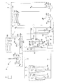
- FIG. 1 is a schematic configuration diagram of a refrigeration cycle device 1 according to an embodiment of the present disclosure.
- the refrigeration cycle apparatus 1 has a main refrigerant circuit 20 in which a main refrigerant circulates and a sub-refrigerant circuit 80 in which a sub-refrigerant circulates, and is a device that performs indoor air conditioning (here, cooling).
- the main refrigerant circuit 20 mainly includes the main compressors 21 and 22, the main heat source side heat exchanger 25, the main use side heat exchangers 72a and 72b, the main expansion mechanism 27, the suction injection pipe 61, and the supercooling.
- the heat exchanger includes a heat exchanger 62 and a sub-use-side heat exchanger 85.
- the main refrigerant circuit 20 has the intermediate heat exchanger 26, the gas-liquid separator 51, the gas vent tube 52, and the main use side expansion mechanisms 71a and 71b. Then, carbon dioxide is sealed in the main refrigerant circuit 20 as a main refrigerant.
- the main compressors 21 and 22 are devices that compress the main refrigerant.
- the first main compressor 21 is a compressor that drives a low-stage compression element 21a such as a rotary or scroll by a drive mechanism such as a motor or an engine.
- the second main compressor 22 is a compressor that drives a high-stage compression element 22a such as a rotary or scroll by a drive mechanism such as a motor or an engine.
- the main compressors 21 and 22 compress the main refrigerant in the low-stage first main compressor 21 and then discharge the main refrigerant, and discharge the main refrigerant discharged from the first main compressor 21 to the high-stage second main compressor 21.
- a multi-stage (here, two-stage) compressor configured to be compressed by the compressor 22 is configured.
- the intermediate heat exchanger 26 is a device that exchanges heat between the main refrigerant and the outdoor air.
- the intermediate heat exchanger 26 functions as a cooler for the main refrigerant flowing between the first main compressor 21 and the second main compressor 22. It is a heat exchanger.
- the main heat source side heat exchanger 25 is a device for exchanging heat between the main refrigerant and the outdoor air, and here is a heat exchanger functioning as a radiator of the main refrigerant.
- One end (inlet) of the main heat source side heat exchanger 25 is connected to the discharge side of the second main compressor 22, and the other end (outlet) is connected to the main expansion mechanism 27.
- the main expansion mechanism 27 is a device that decompresses the main refrigerant.
- the main expansion mechanism 27 is an expansion mechanism that decompresses the main refrigerant flowing between the main heat source side heat exchanger 25 and the main use side heat exchangers 72a and 72b.
- the main expansion mechanism 27 is provided between the other end (outlet) of the main heat source side heat exchanger 25 and the gas-liquid separator 51.
- the main expansion mechanism 27 is, for example, an electric expansion valve.
- the main expansion mechanism 27 may be an expander that generates power by reducing the pressure of the main refrigerant.
- the gas-liquid separator 51 is a device that separates the main refrigerant into gas and liquid.
- the gas-liquid separator 51 is a container that separates the main refrigerant decompressed by the main expansion mechanism 27 into gas and liquid.
- the gas-liquid separator 51 is provided between the main expansion mechanism 27 and the subcooling heat exchanger 62 (one end of the first subcooling channel 62a).
- the gas vent pipe 52 is a refrigerant pipe through which the main refrigerant flows.
- the gas vent pipe 52 is a refrigerant pipe that extracts the gaseous main refrigerant from the gas-liquid separator 51 and sends it to the suction sides of the main compressors 21 and 22.
- the degassing pipe 52 is a refrigerant pipe that sends the gaseous main refrigerant extracted from the gas-liquid separator 51 to the suction side of the first main compressor 21 through the suction injection pipe 61.
- One end of the degassing pipe 52 is connected to communicate with the upper space of the gas-liquid separator 51, and the other end is connected to the suction injection pipe 61 (first suction injection pipe 61a).
- the gas vent tube 52 has a gas vent expansion mechanism 53.
- the degassing expansion mechanism 53 is a device that depressurizes the main refrigerant, and here is an expansion mechanism that depressurizes the main refrigerant flowing through the degassing pipe 52.
- the gas release expansion mechanism 53 is, for example, an electric expansion valve.
- the suction injection pipe 61 is a refrigerant pipe through which the main refrigerant flows.
- the main refrigerant flowing between the main heat source side heat exchanger 25 and the main use side heat exchangers 72a and 72b is branched to form a main compressor 21. , 22 to the suction side.
- the suction injection pipe 61 branches the main refrigerant in a liquid state flowing between the gas-liquid separator 51 and the subcooling heat exchanger 62 (one end of the first subcooling flow path 62a) to the first refrigerant.
- It is a refrigerant pipe to be sent to the suction side of the main compressor 21, and has a first suction injection pipe 61a and a second suction injection pipe 61b.
- One end of the first suction injection pipe 61a is connected between the gas-liquid separator 51 and the subcooling heat exchanger 62 (one end of the first subcooling flow path 62a), and the other end is a subcooling heat exchanger. 62 (one end of the second subcooling channel 62b).
- One end of the second suction injection pipe 61b is connected to the subcooling heat exchanger 62 (the other end of the second subcooling flow path 62b), and the other end is connected to the suction side of the first compressor 21. .
- the suction injection pipe 61 has a suction injection expansion mechanism 63.
- the suction injection expansion mechanism 63 is provided in the first suction injection pipe 61a.
- the suction injection expansion mechanism 63 is a device that decompresses the main refrigerant, and here is an expansion mechanism that depressurizes the main refrigerant flowing through the suction injection pipe 61.
- the suction injection expansion mechanism 63 is, for example, an electric expansion valve.
- the other end of the degassing pipe 52 is connected to the first suction injection pipe 61a between the suction injection expansion mechanism 63 and the subcooling heat exchanger 62 (one end of the second subcooling flow path 62b). I have.
- the supercooling heat exchanger 62 is a device for exchanging heat between the main refrigerants.
- the main refrigerant flowing between the main expansion mechanism 27 and the main use side heat exchangers 72a and 72b flows through the suction injection pipe 61.
- This is a heat exchanger that cools by heat exchange with the main refrigerant.
- the subcooling heat exchanger 62 is a liquid that flows between the gas-liquid separator 51 and the main use side heat exchangers 72a and 72b (the second sub flow path 85b of the sub use side heat exchanger 85).
- the subcooling heat exchanger 62 includes a first supercooling channel 62a through which a main refrigerant flows between the gas-liquid separator 51 and the main use side heat exchangers 72a and 72b, and a main refrigerant flowing through the suction injection pipe 61. And a second supercooling channel 62b for flowing.
- the second subcooling channel 62b has one end (inlet) connected to the other end of the first suction injection pipe 61a, and the other end (outlet) connected to one end of the second suction injection pipe 61b.
- the sub-use-side heat exchanger 85 is a device for exchanging heat between the main refrigerant and the sub-refrigerant, and here, is a cooler for the main refrigerant flowing between the main expansion mechanism 27 and the main use-side heat exchangers 72a and 72b.
- the main use-side expansion mechanisms 71a and 71b are devices that reduce the pressure of the main refrigerant, and here, are expansion mechanisms that reduce the pressure of the main refrigerant flowing between the main expansion mechanism 27 and the main use-side heat exchangers 72a and 72b. .
- the main use side expansion mechanisms 71a and 71b are connected between the sub use side heat exchanger 85 (the other end of the second sub flow path 85b) and one end (entrance) of the main use side heat exchangers 72a and 72b. It is provided between them.
- the main use side expansion mechanisms 71a and 71b are, for example, electric expansion valves.
- the main-use-side heat exchangers 72a and 72b are devices for exchanging heat between the main refrigerant and room air, and here are heat exchangers that function as evaporators for the main refrigerant.
- One end (inlet) of the main use side heat exchangers 72a, 72b is connected to the main use side expansion mechanisms 71a, 71b, and the other end (outlet) is connected to the suction side of the first compressor 21.
- the sub refrigerant circuit 80 mainly includes a sub compressor 81, a sub heat source side heat exchanger 83, and a sub use side heat exchanger 85.
- the sub refrigerant circuit 80 has a sub expansion mechanism 84.
- an HFC refrigerant (R32 or the like) having a GWP (global warming potential) of 750 or less, an HFO refrigerant (R1234yf or R1234ze or the like), or a mixed refrigerant of the HFC refrigerant and the HFO refrigerant (R452B etc.) are enclosed.
- the sub-refrigerant is not limited to these, and may be a natural refrigerant (propane, ammonia, or the like) having a higher coefficient of performance than carbon dioxide.
- the sub compressor 81 is a device that compresses the sub refrigerant.
- the sub-compressor 81 is a compressor that drives a compression element 81a such as a rotary or scroll by a drive mechanism such as a motor or an engine.
- the sub heat source side heat exchanger 83 is a device for exchanging heat between the sub refrigerant and the outdoor air, and here is a heat exchanger functioning as a radiator of the sub refrigerant.
- One end (inlet) of the sub heat source side heat exchanger 83 is connected to the discharge side of the sub compressor 81, and the other end (outlet) is connected to the sub expansion mechanism 84.
- the sub-expansion mechanism 84 is a device that decompresses the sub-refrigerant.
- the sub-expansion mechanism 84 is an expansion mechanism that decompresses the sub-refrigerant flowing between the sub-heat-source-side heat exchanger 83 and the sub-use-side heat exchanger 85.
- the sub expansion mechanism 84 is provided between the other end (outlet) of the sub heat source side heat exchanger 83 and the sub use side heat exchanger 85 (one end of the first sub flow path 85a).
- the sub-expansion mechanism 84 is, for example, an electric expansion valve.
- the sub-use-side heat exchanger 85 is a device that exchanges heat between the main refrigerant and the sub-refrigerant.
- the sub-use-side heat exchanger 85 functions as an evaporator for the sub-refrigerant, and This is a heat exchanger that cools the main refrigerant flowing between the exchangers 72a and 72b.
- the sub-use-side heat exchanger 85 includes a subcooling heat exchanger 62 (the other end of the first subcooling passage 62a) and main use-side heat exchangers 72a and 72b (main use-side expansion mechanism 71a, 71b) is a heat exchanger that cools the main refrigerant flowing between the sub-refrigerant circuit 80 and the main refrigerant flowing through the sub-refrigerant circuit 80.
- the sub-use-side heat exchanger 85 includes a first sub-flow path 85a through which a sub-refrigerant flows between the sub-expansion mechanism 84 and the suction side of the sub-compressor 81, a subcooling heat exchanger 62, and a main-use-side heat exchange. And a second sub flow path 85b through which a main refrigerant flowing between the devices 72a and 72b flows.
- One end (inlet) of the first sub flow path 85 a is connected to the sub expansion mechanism 84, and the other end (outlet) is connected to the suction side of the sub compressor 81.
- One end (inlet) of the second sub flow path 85b is connected to the subcooling heat exchanger 62 (the other end of the first subcooling flow path 62a), and the other end (outlet) is connected to the main use-side expansion mechanism 71a. 71b.
- the components of the main refrigerant circuit 20 and the sub-refrigerant circuit 80 are provided in the heat source unit 2, the plurality of use units 7a and 7b, and the sub-unit 8.
- the use units 7a and 7b are provided corresponding to the main use side heat exchangers 72a and 72b, respectively.
- the heat source unit 2 is arranged outdoors.
- the heat source unit 2 is provided with the main refrigerant circuit 20 excluding the sub use side heat exchanger 85, the main use side expansion mechanisms 71a and 71b, and the main use side heat exchangers 72a and 72b.
- the heat source unit 2 is provided with a heat source side fan 28 for sending outdoor air to the main heat source side heat exchanger 25 and the intermediate heat exchanger 26.
- the heat source side fan 28 is a fan that drives a blowing element such as a propeller fan by a driving mechanism such as a motor.
- the heat source unit 2 is provided with various sensors. Specifically, a pressure sensor 91 and a temperature sensor 92 for detecting the pressure and temperature of the main refrigerant on the suction side of the first main compressor 21 are provided. A pressure sensor 93 that detects the pressure of the main refrigerant on the discharge side of the first main compressor 21 is provided. A pressure sensor 94 and a temperature sensor 95 for detecting the pressure and temperature of the main refrigerant on the discharge side of the second main compressor 21 are provided. A temperature sensor 96 for detecting the temperature of the main refrigerant at the other end (outlet) of the main heat source side heat exchanger 25 is provided.
- a pressure sensor 97 and a temperature sensor 98 for detecting the pressure and temperature of the main refrigerant in the gas-liquid separator 51 are provided.
- a temperature sensor 64 for detecting the temperature of the main refrigerant at the other end of the subcooling heat exchanger 62 (the other end of the first subcooling flow path 62a) is provided.
- a temperature sensor 65 that detects the temperature of the main refrigerant in the second suction injection pipe 61b is provided.
- a temperature sensor 105 for detecting the temperature of the main refrigerant at the other end of the sub-use side heat exchanger 85 (the other end of the second sub flow path 85b) is provided.
- a temperature sensor 99 for detecting the temperature of the outdoor air (outside air temperature) is provided.
- the use units 7a and 7b are arranged indoors.
- the main use side expansion mechanisms 71a, 71b and the main use side heat exchangers 72a, 72b of the main refrigerant circuit 20 are provided in the use units 7a, 7b.
- the use units 7a and 7b are provided with use side fans 73a and 73b for sending room air to the main use side heat exchangers 72a and 72b.
- the indoor fans 73a and 73b are fans that drive a blowing element such as a centrifugal fan or a multi-blade fan by a driving mechanism such as a motor.
- various sensors are provided in the use units 7a and 7b. Specifically, temperature sensors 74a, 74b for detecting the temperature of the main refrigerant at one end (inlet) side of the main use side heat exchangers 72a, 72b, and the other end (exit) of the main use side heat exchangers 72a, 72b. Temperature sensors 75a and 75b for detecting the temperature of the main refrigerant on the side.
- the subunit 8 is arranged outside the room.
- the sub-refrigerant circuit 80 and a part of a refrigerant pipe constituting the main refrigerant circuit 20 are provided in the sub-unit 8. I have.
- the sub unit 8 is provided with a sub fan 86 for sending outdoor air to the sub heat source side heat exchanger 83.
- the sub-side fan 86 is a fan that drives a blowing element such as a propeller fan by a driving mechanism such as a motor.
- the sub-unit 8 is provided adjacent to the heat source unit 2, and the sub-unit 8 and the heat source unit 2 are substantially integrated.
- the subunit 8 may be provided separately from the heat source unit 2, or all the components of the subunit 8 may be provided in the heat source unit 2 and the subunit 8 may be omitted.
- the subunit 8 is provided with various sensors. Specifically, a pressure sensor 101 and a temperature sensor 102 for detecting the pressure and temperature of the sub refrigerant on the suction side of the sub compressor 81 are provided. A pressure sensor 103 and a temperature sensor 104 for detecting the pressure and temperature of the sub-refrigerant on the discharge side of the sub-compressor 81 are provided. A temperature sensor 106 for detecting the temperature of the outdoor air (outside air temperature) is provided.
- the heat source unit 2 and the use units 7a and 7b are connected by main refrigerant communication pipes 11 and 12 that constitute a part of the main refrigerant circuit 20.
- the first main refrigerant communication pipe 11 is a part of a pipe connecting between the sub-use side heat exchanger 85 (the other end of the second sub-flow path 85b) and the main use-side expansion mechanisms 71a and 71b.
- the second main refrigerant communication pipe 12 is a part of a pipe connecting between the other ends of the main use side heat exchangers 72a and 72b and the suction side of the first main compressor 21.
- the control unit 9 controls the components of the heat source unit 2 including the components of the main refrigerant circuit 20 and the sub-refrigerant circuit 80, the units 7a and 7b, and the sub-unit 8.
- the control unit 9 is configured such that control boards and the like provided in the heat source unit 2, the use units 7a and 7b, and the subunit 8 are connected by communication, and various sensors 64, 65, 74a, 74b, 75a, and 75b , 91 to 99, 101 to 106, and the like.
- the control unit 9 is illustrated at a position apart from the heat source unit 2, the use units 7a and 7b, the subunit 8, and the like.
- control unit 9 controls the components 21, 22, and 22 of the refrigeration cycle apparatus 1 based on the detection signals of the various sensors 64, 65, 74 a, 74 b, 75 a, 75 b, 91 to 99, 101 to 106, and the like. Control of 27, 28, 53, 63, 71a, 71b, 73a, 73b, 81, 84, 86, that is, operation control of the entire refrigeration cycle apparatus 1 is performed.
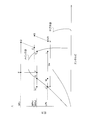
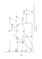
- FIG. 2 is a diagram illustrating the flow of the refrigerant in the refrigeration cycle apparatus 1 during the cooling operation with the supercooling heat exchange cooling operation.
- FIG. 3 is a pressure-enthalpy diagram illustrating a refrigeration cycle during a cooling operation with a supercooling heat exchange cooling operation.
- FIG. 4 is a diagram showing the flow of the refrigerant in the refrigeration cycle apparatus 1 during the cooling operation with the sub-refrigerant circuit cooling operation.
- FIG. 5 is a pressure-enthalpy diagram illustrating a refrigeration cycle during a cooling operation with a sub-refrigerant circuit cooling operation.
- FIG. 6 is a flowchart of switching control between the supercooling heat exchange cooling operation and the sub-refrigerant circuit cooling operation.
- the refrigeration cycle apparatus 1 can perform a cooling operation (cooling operation) in which the main-use-side heat exchangers 72a and 72b function as an evaporator of the main refrigerant to cool the indoor air, as indoor air conditioning.
- a cooling operation cooling operation
- the sub-cooling heat exchange cooling operation of cooling the main refrigerant using the suction injection pipe 61 and the sub-cooling heat exchanger 62 and the main refrigerant cooling using the sub-refrigerant circuit 80 are performed.
- the sub-cooling circuit cooling operation can be switched over.
- the control unit 9 performs the supercooling heat exchange cooling operation, the sub-refrigerant circuit cooling operation, and the operation of the cooling operation including the switching of these operations.
- the low-pressure (LPh) main refrigerant in the refrigeration cycle (see point A in FIGS. 2 and 3) is sucked into the first main compressor 21, and the first main compressor 21 It is compressed to the intermediate pressure (MPh1) in the refrigeration cycle and discharged (see point B in FIGS. 2 and 3).
- the intermediate-pressure main refrigerant discharged from the first main compressor 21 is sent to the intermediate heat exchanger 26, where it is cooled by performing heat exchange with outdoor air sent by the heat source side fan 28 in the intermediate heat exchanger 26. (See point C in FIGS. 2 and 3).
- the intermediate-pressure main refrigerant cooled in the intermediate heat exchanger 26 is sucked into the second main compressor 22, and compressed and discharged to the high pressure (HPh) in the refrigeration cycle in the second main compressor 22 (FIG. 2 and point D in FIG. 3).
- the high-pressure main refrigerant discharged from the second main compressor 22 has a pressure exceeding the critical pressure of the main refrigerant.
- the high-pressure main refrigerant discharged from the second main compressor 22 is sent to the main heat source side heat exchanger 25, and exchanges heat with the outdoor air sent by the heat source side fan 28 in the main heat source side heat exchanger 25. (See point E in FIGS. 2 and 3).
- the high-pressure main refrigerant cooled in the main heat source side heat exchanger 25 is sent to the main expansion mechanism 27, where the main refrigerant is reduced in pressure to the intermediate pressure (MPh2) in the refrigeration cycle, and becomes a gas-liquid two-phase state. (See point F in FIGS. 2 and 3).
- the intermediate pressure (MPh2) is lower than the intermediate pressure (MPh1).
- the intermediate-pressure main refrigerant depressurized in the main expansion mechanism 27 is sent to the gas-liquid separator 51, where the main refrigerant in a gas state (see point K in FIGS. 2 and 3) and the liquid state (See point G in FIGS. 2 and 3).
- the main refrigerant in the gaseous state at the intermediate pressure separated in the gas-liquid separator 51 is extracted from the gas-liquid separator 51 to the degassing pipe 52 according to the degree of opening of the degassing expansion mechanism 53.
- the main refrigerant in the gas state at the intermediate pressure extracted to the gas vent pipe 52 is decompressed to a low pressure (LPh) by the gas vent expansion mechanism 53 (see the point L in FIGS. 2 and 3), and the suction injection pipe 61 (the first point). It is sent to one suction injection pipe 61a downstream of the suction injection expansion mechanism 63).
- the opening degree of the gas release / expansion mechanism 53 is adjusted based on the pressure (MPh2) of the main refrigerant in the gas-liquid separator 51.
- the control unit 9 controls the opening degree of the gas release expansion mechanism 53 so that the pressure (MPh2) of the main refrigerant in the gas-liquid separator 51 becomes the target value MPh2t.
- the intermediate pressure MPh2 is detected by the pressure sensor 97.
- a part of the main refrigerant in the intermediate-pressure liquid state separated in the gas-liquid separator 51 is branched into the suction injection pipe 61 in accordance with the opening degree of the suction injection expansion mechanism 63, and the rest is a subcooling heat exchanger 62. (First supercooling channel 62a).
- the main refrigerant in a liquid state at an intermediate pressure branched into the suction injection pipe 61 is reduced to a low pressure (LPh) by the suction injection expansion mechanism 63 to be in a gas-liquid two-phase state (see point M in FIGS. 2 and 3).
- the refrigerant merges with the low-pressure main refrigerant sent from the degassing pipe 52 and is sent to the subcooling heat exchanger 62 (second subcooling channel 62b).
- the intermediate-pressure liquid refrigerant flowing through the first subcooling flow channel 62a exchanges heat with the low-pressure gas-liquid two-phase main refrigerant flowing through the second supercooling flow channel 62b. And cooled (see point H in FIGS. 2 and 3).
- the low-pressure gas-liquid two-phase main refrigerant flowing through the second supercooling flow channel 62b is heated by heat exchange with the intermediate-pressure liquid main refrigerant flowing through the first supercooling flow channel 62a ( 2 and 3) and is sent to the suction side of the first main compressor 21.
- the opening degree of the suction injection expansion mechanism 63 is adjusted based on the superheat degree SHh1 of the main refrigerant at the outlet of the subcooling heat exchanger 62 on the suction injection pipe 61 side.
- the control unit 9 controls the opening degree of the suction injection expansion mechanism 63 so that the superheat degree SHh1 becomes the target value SHh1t.
- the superheat degree SHh1 is obtained by converting the pressure (LPh) of the main refrigerant detected by the pressure sensor 91 into a saturation temperature, and subtracting this saturation temperature from the temperature of the main refrigerant detected by the temperature sensor 65.
- the intermediate-pressure main refrigerant cooled in the subcooling heat exchanger 62 passes through the sub-use-side heat exchanger 85 (second sub-flow path 85b) (see point I in FIGS. 2 and 3), and then the first refrigerant flows into the first refrigerant.
- the air is sent to the main use side expansion mechanisms 71a and 71b through the main refrigerant communication pipe 11, and is reduced to a low pressure (LPh) in the main use side expansion mechanisms 71a and 71b to be in a gas-liquid two-phase state (FIGS. 2 and FIG. 3 point J).
- the sub-use-side heat exchanger 85 exchanges heat between the main refrigerant and the sub-refrigerant. Is not performed (see points H and I in FIGS. 2 and 3).
- the low-pressure main refrigerant decompressed in the main use side expansion mechanisms 71a, 71b is sent to the main use side heat exchangers 72a, 72b, and sent by the use side fans 73a, 73b in the main use side heat exchangers 72a, 72b. It heats and evaporates by performing heat exchange with the room air to be produced (see point A in FIGS. 2 and 3). Conversely, the indoor air is cooled by performing heat exchange with the low-pressure two-phase main refrigerant flowing through the main use side heat exchangers 72a and 72b, thereby cooling the room.
- the low-pressure main refrigerant evaporated in the main-use-side heat exchangers 72a and 72b is sent to the suction side of the first main compressor 21 through the second main refrigerant communication pipe 12, and together with the main refrigerant that merges from the suction injection pipe 61. Is again sucked into the first main compressor 21. In this manner, the cooling operation involving the supercooling heat exchange cooling operation is performed.
- the low-pressure (LPh) main refrigerant in the refrigeration cycle (see point A in FIGS. 4 and 5) is sucked into the first main compressor 21, and It is compressed and discharged to the intermediate pressure (MPh1) in the refrigeration cycle (see point B in FIGS. 4 and 5).
- the intermediate-pressure main refrigerant discharged from the first main compressor 21 is sent to the intermediate heat exchanger 26, where it is cooled by performing heat exchange with outdoor air sent by the heat source side fan 28 in the intermediate heat exchanger 26. (See point C in FIGS. 4 and 5).
- the intermediate-pressure main refrigerant cooled in the intermediate heat exchanger 26 is sucked into the second main compressor 22, and compressed and discharged to the high pressure (HPh) in the refrigeration cycle in the second main compressor 22 (FIG. 4 and point D in FIG. 5).
- the high-pressure main refrigerant discharged from the second main compressor 22 has a pressure exceeding the critical pressure of the main refrigerant.
- the high-pressure main refrigerant discharged from the second main compressor 22 is sent to the main heat source side heat exchanger 25, and exchanges heat with the outdoor air sent by the heat source side fan 28 in the main heat source side heat exchanger 25. And cooled (see point E in FIGS. 4 and 5).
- the high-pressure main refrigerant cooled in the main heat source side heat exchanger 25 is sent to the main expansion mechanism 27, where the main refrigerant is reduced in pressure to the intermediate pressure (MPh2) in the refrigeration cycle, and becomes a gas-liquid two-phase state. (See point F in FIGS. 4 and 5).
- the intermediate pressure (MPh2) is lower than the intermediate pressure (MPh1).
- the intermediate-pressure main refrigerant reduced in the main expansion mechanism 27 is sent to the gas-liquid separator 51, where the main refrigerant in a gas state (see point K in FIGS. 4 and 5) and the liquid state (See point G in FIGS. 4 and 5).
- the main refrigerant in the gaseous state at the intermediate pressure separated in the gas-liquid separator 51 is extracted from the gas-liquid separator 51 to the degassing pipe 52 according to the degree of opening of the degassing expansion mechanism 53.
- the main refrigerant in the gaseous state at the intermediate pressure extracted to the gas vent pipe 52 is decompressed to a low pressure (LPh) by the gas vent expansion mechanism 53 (see the point L in FIGS. 4 and 5), and the suction injection pipe 61 (the first point). It is sent to one suction injection pipe 61a downstream of the suction injection expansion mechanism 63).
- the opening degree of the gas vent expansion mechanism 53 is adjusted based on the pressure (MPh2) of the main refrigerant in the gas-liquid separator 51.
- control unit 9 controls the opening degree of the gas release expansion mechanism 53 so that the pressure (MPh2) of the main refrigerant in the gas-liquid separator 51 becomes the target value MPh2s.
- the intermediate pressure MPh2 is detected by the pressure sensor 97.
- the main refrigerant in the intermediate-pressure liquid state separated in the gas-liquid separator 51 does not branch to the suction injection pipe 61 because the suction injection expansion mechanism 63 is closed, and the subcooling heat exchanger 62 (the It is sent to one subcooling channel 62a). Therefore, only the low-pressure main refrigerant sent from the degassing pipe 53 flows through the suction injection pipe 61, and this low-pressure main refrigerant flows into the subcooling heat exchanger 62 (second subcooling flow path 62b). Sent.
- the intermediate-pressure liquid refrigerant flowing through the first subcooling flow channel 62a exchanges heat with the low-pressure gas-liquid two-phase main refrigerant flowing through the second supercooling flow channel 62b. And cooled (see point H in FIGS. 4 and 5).
- the low-pressure gas-liquid two-phase main refrigerant flowing through the second supercooling flow channel 62b is heated by heat exchange with the intermediate-pressure liquid main refrigerant flowing through the first supercooling flow channel 62a ( 4 and 5) and is sent to the suction side of the first main compressor 21.
- the low-pressure (LPs) sub-refrigerant (see point R in FIGS. 4 and 5) in the refrigeration cycle is sucked into the sub-compressor 81, and (HPs) and discharged (see point S in FIGS. 4 and 5).
- the high-pressure sub-refrigerant discharged from the sub-compressor 81 is sent to the sub-heat-source-side heat exchanger 83, and in the sub-heat-source-side heat exchanger 83, performs heat exchange with outdoor air sent by the sub-side fan 86 to be cooled. (See point T in FIGS. 4 and 5).
- the high-pressure sub-refrigerant cooled in the sub-heat-source-side heat exchanger 83 is sent to the sub-expansion mechanism 84, where it is depressurized to a low pressure and enters a gas-liquid two-phase state (FIGS. 4 and 5). Point U).
- the intermediate-pressure main refrigerant flowing through the second sub-flow path 85b exchanges heat with the low-pressure gas-liquid two-phase sub-refrigerant flowing through the first sub-flow path 85a. It is cooled (see point I in FIGS. 4 and 5). Conversely, the low-pressure gas-liquid two-phase sub-refrigerant flowing through the first sub-flow path 85a exchanges heat with the intermediate-pressure main refrigerant flowing through the second sub-flow path 85b and is heated (see FIGS. 4 and 5). (Refer to the point R of 5)), and is sucked into the suction side of the sub-compressor 81 again.
- the operating capacity of the sub-compressor 81 is adjusted based on the low-pressure LPs of the sub-refrigerant circuit 80.
- the control unit 9 controls the operating capacity (operating frequency and rotation speed) of the sub-compressor 81 so that the low pressure LPs becomes the target value LPst.
- the low pressure LPs is detected by the pressure sensor 101.
- the degree of opening of the sub-expansion mechanism 84 is adjusted based on the superheat degree SHs1 of the sub-refrigerant at the outlet of the sub-use-side heat exchanger 85 on the sub-refrigerant circuit 80 side.
- control unit 9 controls the opening of the sub-expansion mechanism 84 so that the superheat degree SHs1 becomes the target value SHs1t.
- the superheat degree SHs1 is obtained by converting the pressure (LPs) of the sub-refrigerant detected by the pressure sensor 101 into a saturation temperature, and subtracting this saturation temperature from the temperature of the sub-refrigerant detected by the temperature sensor 102.
- the intermediate-pressure main refrigerant cooled in the sub-use-side heat exchanger 85 is sent to the main use-side expansion mechanisms 71a and 71b through the first main refrigerant communication pipe 11, and the low-pressure main refrigerant is reduced in the main use-side expansion mechanisms 71a and 71b.
- the pressure is reduced to (LPh), and a gas-liquid two-phase state is established (see point J in FIGS. 4 and 5).
- the low-pressure main refrigerant decompressed in the main use side expansion mechanisms 71a, 71b is sent to the main use side heat exchangers 72a, 72b, and sent by the use side fans 73a, 73b in the main use side heat exchangers 72a, 72b. Heat is exchanged with the room air to be heated and evaporated (see point A in FIGS. 4 and 5). Conversely, the indoor air is cooled by performing heat exchange with the low-pressure two-phase main refrigerant flowing through the main use side heat exchangers 72a and 72b, thereby cooling the room.
- the low-pressure main refrigerant evaporated in the main-use-side heat exchangers 72a and 72b is sent to the suction side of the first main compressor 21 through the second main refrigerant communication pipe 12, and together with the main refrigerant that merges from the suction injection pipe 61. Is again sucked into the first main compressor 21. In this way, the cooling operation with the sub-refrigerant circuit cooling operation is performed.
- the enthalpy of the refrigerant sent to the main use side heat exchangers 72a and 72b decreases, and the heat exchange obtained by evaporation of the refrigerant in the main use side heat exchangers 72a and 72b
- the capacity Qe evaporation capacity of the main use side heat exchanger
- the heat radiating ability of the main refrigerant in the main heat source side heat exchanger 25 is reduced. Accordingly, even when the supercooling heat exchange cooling operation is performed, the main use side heat exchange is performed.
- the enthalpy of the refrigerant sent to the heat exchangers 72a, 72b does not sufficiently decrease, and this tends to make it difficult to increase the evaporation capacity of the main use side heat exchangers 72a, 72b.
- carbon dioxide having a low coefficient of performance as compared with an HFC refrigerant or the like is used as the main refrigerant, this tendency becomes remarkable.
- the heat radiation capability of the main refrigerant in the main heat source side heat exchanger 25 increases, and accordingly, the main use side heat exchanger only needs to perform the supercooling heat exchange cooling operation.
- the enthalpy of the refrigerant sent to 72a, 72b is sufficiently reduced (see points H, I, J in FIG. 3), whereby it is easy to increase the evaporation capacity Qe of the main use side heat exchangers 72a, 72b. Tend to be.
- control unit 9 switches between the supercooling heat exchange cooling operation and the sub-refrigerant circuit cooling operation according to the state quantity such as the outside air temperature Ta.
- step ST1 the control unit 9 performs the cooling operation with the supercooling heat exchange cooling operation. That is, the control unit 9 starts the supercooling heat exchange cooling operation by opening the suction injection expansion mechanism 63 in a state where the sub compressor 81 is stopped (that is, a state in which the sub refrigerant circuit cooling operation is stopped). .
- step ST2 the control unit 9 determines whether or not the condition of the state quantity such as the outside air temperature Ta for performing only the sub-refrigerant circuit cooling operation (first switching condition) is satisfied.
- the first switching condition is a condition of a state quantity such as an outside air temperature Ta for determining whether to perform only the sub-refrigerant circuit cooling operation of the sub-refrigerant circuit cooling operation and the supercooling heat exchange cooling operation.
- the coefficient of performance of the refrigeration cycle apparatus 1 decreases. Tend to be. When this tendency becomes stronger, it is better to lower the enthalpy of the main refrigerant sent to the main use side heat exchangers 72a and 72b by the sub refrigerant circuit cooling operation, even if the energy consumption of the sub compressor 81 is taken into consideration. A condition is reached in which the coefficient of performance of the device 1 increases.
- the condition under which the performance coefficient of the refrigeration cycle apparatus 1 is higher when performing the sub-refrigerant circuit cooling operation than when performing the subcooling heat exchange cooling operation is defined as the first switching condition.
- the state variables for determining whether the first switching condition is satisfied include the outside air temperature Ta, the temperature Th1 of the main refrigerant in the main heat source side heat exchanger 25, and the subcooling of the main refrigerant at the outlet of the subcooling heat exchanger 62.
- the degree SCh1 or the degree of supercooling SCh2 of the main refrigerant at the outlet of the sub-use side heat exchanger 85 is used.
- the outside air temperature Ta is detected by the temperature sensor 99 or the temperature sensor 106.
- Temperature Th1 is detected by temperature sensor 96.
- the degree of supercooling SCh1 is obtained by subtracting the temperature of the main refrigerant detected by the temperature sensor 64 from the temperature of the main refrigerant detected by the temperature sensor 98.
- the degree of supercooling SCh2 is obtained by subtracting the temperature of the main refrigerant detected by the temperature sensor 105 from the temperature of the main refrigerant detected by the temperature sensor 98.
- step ST2 when the outside air temperature Ta is equal to or higher than the first temperature Tat1, and when the temperature Th1 is equal to or higher than the second temperature Th1t1, the subcooling degree SCh1 is equal to or lower than the first subcooling degree SCh1t1.
- the degree of supercooling SCh2 is equal to or less than the second degree of subcooling SCh2t1
- the first switching condition is satisfied. That is, in the supercooling heat exchange cooling operation, it is determined that the enthalpy of the main refrigerant sent to the main use side heat exchangers 72a and 72b is not sufficiently reduced.
- the first temperature Tat1 and the second temperature Th1t1 are set at about 30 to 45 ° C.
- the first subcooling degree SCh1t1 and the second subcooling degree SCh2t1 are set at about 0 to 5 ° C.
- step ST2 If the state quantity such as the outside air temperature Ta does not satisfy the first switching condition in step ST2, the control unit 9 continues the supercooling heat exchange cooling operation in step ST1 and executes the state quantity such as the outside air temperature Ta. If the first switching condition is satisfied, the process proceeds to step ST3 to switch from the supercooling heat exchange cooling operation to the sub refrigerant circuit cooling operation. That is, the control unit 9 stops the subcooling heat exchange cooling operation by closing the suction injection expansion mechanism 63, and performs the sub-refrigerant circuit cooling operation by operating the sub-compressor 81. Thereby, the enthalpy of the main refrigerant sent to the main use side heat exchangers 72a and 72b by the sub refrigerant circuit cooling operation can be sufficiently reduced.
- step ST4 the control unit 9 determines whether or not the condition of the state quantity such as the outside air temperature Ta for performing only the supercooling heat exchange cooling operation (second switching condition) is satisfied.
- the second switching condition is a condition of a state quantity such as an outside air temperature Ta for determining whether to perform only the subcooling heat exchange cooling operation among the sub refrigerant circuit cooling operation and the supercooling heat exchange cooling operation.
- the coefficient of performance of the refrigeration cycle apparatus 1 increases. Tend to be. When this tendency becomes stronger, it is better to perform the sub-refrigerant circuit cooling operation to lower the enthalpy of the main refrigerant sent to the main use side heat exchangers 72a and 72b, considering the energy consumption of the sub-compressor 81. A condition is reached where the coefficient of performance of the device 1 is low.
- the condition that the coefficient of performance of the refrigeration cycle apparatus 1 is higher when performing the supercooling heat exchange cooling operation than the sub refrigerant circuit cooling operation is defined as the second switching condition.
- the state quantities for determining whether the second switching condition is satisfied include the outside air temperature Ta, the temperature Th1 of the main refrigerant in the main heat source side heat exchanger 25, the supercooling heat exchanger 62 as in the first switching condition. , Or the subcooling degree SCh2 of the main refrigerant at the outlet of the sub-use-side heat exchanger 85 is used.
- step ST4 when the outside air temperature Ta is equal to or lower than the third temperature Tat2, when the temperature Th1 is equal to or lower than the fourth temperature Th1t2, the controller 9 sets the supercooling degree SCh1 to be equal to or higher than the third subcooling degree SCh1t2. In this case, or when the degree of subcooling SCh2 is equal to or greater than the fourth degree of subcooling SCh2t2, it is determined that the second switching condition is satisfied. That is, it is determined that the enthalpy of the main refrigerant sent to the main use side heat exchangers 72a and 72b is sufficiently reduced by the supercooling heat exchange cooling operation.
- the third temperature Tat2 and the fourth temperature Th1t2 are set to lower temperatures (about 10 to 25 ° C.) than the first temperature Tat1 and the second temperature Th1t1, and the third degree of supercooling SCh1t2 and the fourth degree of supercooling are set.
- SCh2t2 is set to a degree of supercooling (about 10 to 15 ° C.) larger than the first degree of subcooling SCh1t1 and the second degree of subcooling SCh2t1.
- step ST4 If the state quantity such as the outside air temperature Ta does not satisfy the second switching condition in step ST4, the control unit 9 continues the sub-refrigerant circuit cooling operation in step ST3, and the state quantity such as the outside air temperature Ta becomes If the second switching condition is satisfied, the process proceeds to step ST1 to switch from the sub refrigerant circuit cooling operation to the supercooling heat exchange cooling operation. That is, the control unit 9 stops the sub-refrigerant circuit cooling operation by stopping the sub-compressor 81, and performs the supercooling heat exchange cooling operation by opening the suction injection expansion mechanism 63. Thereby, the enthalpy of the main refrigerant sent to the main use side heat exchangers 72a and 72b by the supercooling heat exchange cooling operation can be sufficiently reduced.
- the cooling operation with the sub refrigerant circuit cooling operation is performed, and the second switching condition such as the low outside air temperature Ta is satisfied.
- a cooling operation involving a supercooling heat exchange cooling operation is performed.
- the outside air temperature Ta is between the first switching condition and the second switching condition such as medium, the cooling operation with the supercooling heat exchange cooling operation or the sub refrigerant circuit cooling operation is performed. .
- ⁇ A> ⁇ A>
- the main refrigerant circuit 20 in which the main refrigerant circulates provided with the same suction injection pipe 61 and supercooling heat exchanger 62 as in the related art, but also a sub refrigerant different from the main refrigerant circuit 20 is provided.
- a circulating sub-refrigerant circuit 80 is provided.
- the sub-use-side heat exchanger 85 which functions as an evaporator for the sub-refrigerant provided in the sub-refrigerant circuit 80, cools the main refrigerant flowing between the main expansion mechanism 27 and the main use-side heat exchangers 72a, 72b. It is provided in the main refrigerant circuit 20 so as to function as a heat exchanger.
- the same suction injection pipe 61 and supercooling heat exchanger 62 as in the prior art are used to cool the main refrigerant flowing between the main expansion mechanism 27 and the main use side heat exchangers 72a and 72b.
- the sub refrigerant circuit cooling operation of cooling the refrigerant flowing between the main expansion mechanism 27 and the main use side heat exchangers 72a and 72b using the sub refrigerant circuit 80 can be performed.
- the main utilization side heat operation is performed in the supercooling heat exchange cooling operation.
- the enthalpy of the main refrigerant sent to the exchangers 72a, 72b does not sufficiently decrease, the enthalpy of the main refrigerant sent to the main use side heat exchangers 72a, 72b is sufficiently reduced by the sub-refrigerant circuit cooling operation. As a result, the evaporation capacity Qe of the main use side heat exchangers 72a and 72b can be increased.
- the evaporation of the use-side heat exchangers 72a and 72b is independent of the operating conditions.
- the ability Qe can be increased.
- the condition of the state quantity such as the outside air temperature Ta for performing only the sub-refrigerant circuit cooling operation (first switching condition) is defined.
- the enthalpy of the main refrigerant sent to the main use side heat exchangers 72a and 72b is hardly reduced even when the supercooling heat exchange cooling operation is performed due to an increase in the outside air temperature Ta, etc.
- the performance of the refrigeration cycle apparatus 1 The coefficient tends to be low. When this tendency becomes stronger, it is better to lower the enthalpy of the main refrigerant sent to the main use side heat exchangers 72a and 72b by the sub refrigerant circuit cooling operation, even if the energy consumption of the sub compressor 81 is taken into consideration.
- the state quantities used for the determination of the first switching condition are the outside air temperature Ta, the temperature Th1 of the main refrigerant in the main heat source side heat exchanger 25, and the subcooling of the main refrigerant at the outlet of the subcooling heat exchanger 62.
- the degree SCh1 or the supercooling degree SCh2 of the main refrigerant at the outlet of the sub-use-side heat exchanger 85 is four, but any one of these state quantities may be used, or two. Alternatively, three state quantities may be used.
- the condition of the state quantity such as the outside air temperature Ta for performing only the supercooling heat exchange cooling operation (second switching condition) is defined.
- the refrigeration cycle apparatus The coefficient of performance of 1 tends to increase. When this tendency becomes stronger, it is better to perform the sub-refrigerant circuit cooling operation to lower the enthalpy of the main refrigerant sent to the main use side heat exchangers 72a and 72b, considering the energy consumption of the sub-compressor 81.
- the condition that the coefficient of performance of the refrigeration cycle apparatus 1 is higher when performing the supercooling heat exchange cooling operation than the sub-refrigerant circuit cooling operation is set as described above under the third temperature Tat2, the fourth temperature Th1t2, It is defined as a third degree of subcooling SCh1t2 and a fourth degree of subcooling SCh2t2.
- the state quantities used for the determination of the second switching condition are the outside air temperature Ta, the temperature Th1 of the main refrigerant in the main heat source side heat exchanger 25, and the subcooling of the main refrigerant at the outlet of the subcooling heat exchanger 62.
- the degree SCh1 or the supercooling degree SCh2 of the main refrigerant at the outlet of the sub-use-side heat exchanger 85 is four, but any one of these state quantities may be used, or two. Alternatively, three state quantities may be used.
- control unit 9 performs the sub-refrigerant circuit cooling operation by operating the sub-compressor 81, and stops the sub-refrigerant circuit cooling operation by stopping the sub-compressor 81. Further, the control unit 9 controls the operating capacity of the sub compressor 81 during the sub refrigerant circuit cooling operation.
- the cooling capacity of the sub-use heat exchanger 85 can be adjusted by changing the flow rate of the sub-refrigerant circulating in the sub-refrigerant circuit 80.
- the suction injection pipe 61 has the suction injection expansion mechanism 63. Then, the control section 9 performs the supercooling heat exchange cooling operation by opening the suction injection expansion mechanism 63 and stops the supercooling heat exchange cooling operation by closing the suction injection expansion mechanism 63. The control unit 9 controls the opening degree of the suction injection expansion mechanism 63 during the supercooling heat exchange cooling operation.
- the cooling capacity of the supercooling heat exchanger 62 can be adjusted by changing the flow rate of the main refrigerant flowing through the suction injection pipe 63.
- the suction injection pipe 61 branches the main refrigerant in a liquid state flowing between the gas-liquid separator 51 and the subcooling heat exchanger 62, and the subcooling heat exchanger 62 Is provided between the gas-liquid separator 51 and the main use side heat exchangers 72a and 72b.
- the supercooling heat exchanger 62 not only the main refrigerant flowing through the suction injection pipe 61 but also the main refrigerant extracted from the gas-liquid separator 51 by the degassing pipe 52 flows as a cooling source of the main refrigerant. it can.
- the main refrigerant flowing through the suction injection pipe 61 and the degassing pipe 52 flows through the supercooling heat exchanger 62 due to the opening operation of the suction injection expansion mechanism 63, and the supercooling heat exchange
- the cooling operation is stopped, only the main refrigerant flowing through the degassing pipe 52 flows through the subcooling heat exchanger 62 by the closing operation of the suction injection expansion mechanism 63. That is, here, merely performing the cooling operation in the supercooling heat exchanger 62 by only the main refrigerant flowing through the degassing pipe 52 does not mean that the supercooling heat exchange cooling operation is being performed (the supercooling heat exchange cooling operation is not performed).
- the gas-liquid separator 51 and the main use side heat exchanger 72a in the subcooling heat exchanger 62 are used here both in the supercooling heat exchange cooling operation and when the supercooling heat exchange cooling operation is stopped.
- 72b can be cooled by at least the main refrigerant flowing through the degassing pipe 52.
- ⁇ G> carbon dioxide is used as the main refrigerant, and a low GWP refrigerant or a natural refrigerant having a higher coefficient of performance than carbon dioxide is used as the sub-refrigerant.
- the load can be reduced.
- the cooling operation with the supercooling heat exchange cooling operation and the sub-refrigerant circuit cooling operation is performed. To do.
- the cooling operation involving the subcooling heat exchange cooling operation and the sub-refrigerant circuit cooling operation is, as shown in FIGS. 7 and 8, the supercooling heat exchange cooling by opening the suction injection expansion mechanism 63 during the cooling operation.
- the sub-compressor 81 is operated to perform the sub-refrigerant circuit cooling operation.
- the cooling operation involving the supercooling heat exchange cooling operation and the sub-refrigerant circuit cooling operation the main refrigerant at the intermediate pressure (MPh2) separated in the gas-liquid separator 51 (see point G in FIGS.
- the cooling is performed in the cooling heat exchanger 62 (see point H in FIGS. 7 and 8), and thereafter, the cooling is also performed in the sub-use-side heat exchanger 85 (see point I in FIGS. 7 and 8).
- the supercooling heat exchanger 62 compared with the case where only the sub-refrigerant circuit cooling operation is performed (see point H in FIG. 5), the amount of cooling heat of the main refrigerant is larger, and only the supercooling heat exchange cooling operation is performed.
- the amount of cooling heat of the main refrigerant is smaller than in the case of performing (see point H in FIG. 3). Then, the cooling heat amount of the main refrigerant, which is insufficient in the supercooling heat exchange cooling operation, is supplemented in the sub-use side heat exchanger 85, similarly to the cooling operation involving the supercooling heat exchange cooling operation or the sub refrigerant circuit cooling operation, The enthalpy of the refrigerant sent to the main use side heat exchangers 72a and 72b is sufficiently reduced.
- a sub-refrigerant circuit capable of cooling the main refrigerant to a lower temperature level than the subcooling heat exchanger 62
- the sub-use-side heat exchanger 85 of 80 is preferably provided downstream of the subcooling heat exchanger 62, that is, between the subcooling heat exchanger 62 and the main use-side heat exchangers 72a and 72b.
- the cooling operation involving the supercooling heat exchange cooling operation and the sub-refrigerant circuit cooling operation is performed when the outside air temperature Ta is between the first switching condition and the second switching condition such as medium. That is, it is performed when both the first switching condition and the second switching condition are not satisfied.
- the supercooling heat exchange cooling operation is continued, and the second switching condition is satisfied in step ST4. If not, the sub refrigerant circuit cooling operation is continued.
- the supercooling heat exchange cooling operation and the sub refrigerant circuit in step ST5 are performed. Both cooling operations are performed.
- an intermediate injection pipe 31 and an economizer heat exchanger 32 may be provided between the main heat source side heat exchanger 25 and the main expansion mechanism 27.
- the intermediate injection pipe 31 is a refrigerant pipe through which the main refrigerant flows.
- the intermediate injection pipe 31 branches the main refrigerant flowing between the main heat source side heat exchanger 25 and the main use side heat exchangers 72a and 72b.
- the intermediate injection pipe 31 is a refrigerant pipe that branches the main refrigerant flowing between the main heat source side heat exchanger 25 and the main expansion mechanism 27 and sends the branched main refrigerant to the suction side of the second main compressor 22. It has a first intermediate injection pipe 31a and a second intermediate injection pipe 31b.
- first intermediate injection pipe 31a is connected between the other end of the main heat source side heat exchanger 25 and the economizer heat exchanger 32 (one end of the first economizer flow path 32a), and the other end is connected to the economizer heat exchanger. It is connected to the exchanger 32 (one end of the second economizer flow path 32b).
- the second intermediate injection pipe 31b has one end connected to the economizer heat exchanger 32 (the other end of the second economizer flow path 32b), and the other end connected to the outlet of the intermediate heat exchanger 26 and the second main compressor 22. It is connected between the suction side.
- the intermediate injection pipe 31 has an intermediate injection expansion mechanism 33.
- the intermediate injection expansion mechanism 33 is provided in the first intermediate injection pipe 31a.
- the intermediate injection expansion mechanism 33 is a device that decompresses the main refrigerant, and here is an expansion mechanism that depressurizes the main refrigerant flowing through the intermediate injection pipe 31.
- the intermediate injection expansion mechanism 33 is, for example, an electric expansion valve.
- the economizer heat exchanger 32 is a device for exchanging heat between the main refrigerants.
- the economizer heat exchanger 32 transfers the main refrigerant flowing between the main heat source side heat exchanger 25 and the main use side heat exchangers 72a and 72b to the intermediate injection pipe 31.
- the economizer heat exchanger 32 is a heat exchanger that cools the main refrigerant flowing between the main heat source side heat exchanger 25 and the main expansion mechanism 27 by heat exchange with the main refrigerant flowing through the intermediate injection pipe 31. It is.
- the economizer heat exchanger 32 includes a first economizer flow path 32a through which the main refrigerant flowing between the main heat source side heat exchanger 25 and the main expansion mechanism 27 flows, and a second economizer flow through which the main refrigerant flows through the intermediate injection pipe 31. Road 32b.
- One end (inlet) of the first economizer flow path 32 a is connected to the other end of the main heat source side heat exchanger 25, and the other end (outlet) is connected to the inlet of the main expansion mechanism 27.
- One end (inlet) of the second economizer flow path 32b is connected to the other end of the first intermediate injection pipe 31a, and the other end (outlet) is connected to one end of the second intermediate injection pipe 31b.
- control unit 9 performs control to open the intermediate injection expansion mechanism 33, thereby further cooling the main refrigerant radiated in the main heat source side heat exchanger 25 and compressing the main compressors 21 and 22.
- An operation of sending the main refrigerant to the middle of the stroke (here, the suction side of the second main compressor 22) and cooling the main refrigerant sucked into the second main compressor 22 can be performed.
- the multi-stage compressor is constituted by the plurality of main compressors 21 and 22.
- the present invention is not limited to this, and one unit having the compression elements 21a and 21b is provided.
- a multi-stage compressor may be constituted by the main compressor.
- the main compressor may be a single-stage compressor.
- the intermediate injection pipe 31 when performing the intermediate pressure injection as in the second modification, may be connected to the intermediate injection port of the single-stage compressor.
- the present disclosure discloses a compressor that branches a refrigerant flowing between a heat source side heat exchanger and a use side heat exchanger into a refrigerant circuit having a compressor, a heat source side heat exchanger, an expansion mechanism, and a use side heat exchanger. And a subcooling heat exchanger that cools the refrigerant flowing between the expansion mechanism and the use-side heat exchanger by heat exchange with the refrigerant flowing through the suction injection pipe. It is widely applicable to refrigeration cycle devices.
Abstract
運転条件によらずに利用側熱交換器の蒸発能力を大きくするために、メイン冷媒が循環するメイン冷媒回路(20)に、吸入インジェクション管(61)及び過冷却熱交換器(62)を設ける。さらに、メイン冷媒回路(20)とは別のサブ冷媒が循環するサブ冷媒回路(80)を設ける。制御部(9)は、吸入インジェクション管(61)及び過冷却熱交換器(62)を使用してメイン利用側熱交換器(72a、72b)に送るメイン冷媒を冷却する過冷却熱交冷却動作と、サブ冷媒回路(80)を使用してメイン利用側熱交換器(72a、72b)に送るメイン冷媒を冷却するサブ冷媒回路冷却動作と、を切り換える制御を行う。
Description
圧縮機、熱源側熱交換器、膨張機構及び利用側熱交換器を有する冷媒回路に、熱源側熱交換器と利用側熱交換器との間を流れる冷媒を分岐して圧縮機の吸入側に送る吸入インジェクション管、及び、膨張機構と利用側熱交換器との間を流れる冷媒を吸入インジェクション管を流れる冷媒との熱交換によって冷却する過冷却熱交換器、が設けられている冷凍サイクル装置
従来より、圧縮機、熱源側熱交換器、膨張機構及び利用側熱交換器を有する冷媒回路を含む冷凍サイクル装置がある。このような冷凍サイクル装置として、特許文献1(特開2013-139938号公報)に示すように、冷媒回路に、熱源側熱交換器と利用側熱交換器との間を流れる冷媒を分岐して圧縮機の吸入側に送る吸入インジェクション管、及び、膨張機構と利用側熱交換器との間を流れる冷媒を吸入インジェクション管を流れる冷媒との熱交換によって冷却する過冷却熱交換器、が設けられているものがある。
上記従来の冷凍サイクル装置では、冷媒回路に吸入インジェクション管及び過冷却熱交換器が設けられているため、膨張機構と利用側熱交換器との間を流れる冷媒を、熱源側熱交換器と利用側熱交換器との間から分岐されて圧縮機の吸入側に送られる冷媒によって冷却する動作(過冷却熱交冷却動作)を行うことができる。そして、この過冷却熱交冷却動作によって、利用側熱交換器に送られる冷媒のエンタルピが低下し、利用側熱交換器における冷媒の蒸発によって得られる熱交換能力(利用側熱交換器の蒸発能力)を大きくすることができる。
しかし、外気温度等の運転条件によっては、利用側熱交換器の蒸発能力を大きくすることが難しくなる場合がある。
このため、冷媒回路に吸入インジェクション管及び過冷却熱交換器が設けられている冷凍サイクル装置においては、運転条件によらずに、利用側熱交換器の蒸発能力を大きくできるようにすることが望まれる。
第1の観点にかかる冷凍サイクル装置は、メイン冷媒回路と、サブ冷媒回路と、メイン冷媒回路及びサブ冷媒回路の構成機器を制御する制御部と、を有している。メイン冷媒回路は、メイン圧縮機と、メイン熱源側熱交換器と、メイン利用側熱交換器と、メイン膨張機構と、吸入インジェクション管と、過冷却熱交換器と、を有している。メイン圧縮機は、メイン冷媒を圧縮する圧縮機である。メイン熱源側熱交換器は、メイン冷媒の放熱器として機能する熱交換器である。メイン利用側熱交換器は、メイン冷媒の蒸発器として機能する熱交換器である。メイン膨張機構は、メイン熱源側熱交換器とメイン利用側熱交換器との間を流れるメイン冷媒を減圧する膨張機構である。吸入インジェクション管は、メイン熱源側熱交換器とメイン利用側熱交換器との間を流れるメイン冷媒を分岐してメイン圧縮機の吸入側に送る冷媒管である。過冷却熱交換器は、メイン膨張機構とメイン利用側熱交換器との間を流れるメイン冷媒を吸入インジェクション管を流れるメイン冷媒との熱交換によって冷却する熱交換器である。また、メイン冷媒回路は、メイン膨張機構とメイン利用側熱交換器との間を流れるメイン冷媒の冷却器として機能するサブ利用側熱交換器を有している。サブ冷媒回路は、サブ圧縮機と、サブ熱源側熱交換器と、サブ利用側熱交換器と、を有している。サブ圧縮機は、サブ冷媒を圧縮する圧縮機である。サブ熱源側熱交換器は、サブ冷媒の放熱器として機能する熱交換器である。サブ利用側熱交換器は、サブ冷媒の蒸発器として機能してメイン膨張機構とメイン利用側熱交換器との間を流れるメイン冷媒を冷却する熱交換器である。そして、制御部は、外気温度、メイン熱源側熱交換器におけるメイン冷媒の温度、過冷却熱交換器の出口におけるメイン冷媒の過冷却度、又は、サブ利用側熱交換器の出口におけるメイン冷媒の過冷却度に応じて、吸入インジェクション管及び過冷却熱交換器を使用してメイン冷媒を冷却する過冷却熱交冷却動作とサブ冷媒回路を使用してメイン冷媒を冷却するサブ冷媒回路冷却動作とを切り換える。
ここでは、上記のように、メイン冷媒が循環するメイン冷媒回路に従来と同様の吸入インジェクション管及び過冷却熱交換器を設けるだけでなく、メイン冷媒回路とは別のサブ冷媒が循環するサブ冷媒回路を設けている。そして、サブ冷媒回路に設けられたサブ冷媒の蒸発器として機能するサブ利用側熱交換器を、メイン膨張機構とメイン利用側熱交換器との間を流れるメイン冷媒を冷却する熱交換器として機能するように、メイン冷媒回路に設けている。このため、ここでは、従来と同様の吸入インジェクション管及び過冷却熱交換器を使用してメイン膨張機構とメイン利用側熱交換器との間を流れるメイン冷媒を冷却する過冷却熱交冷却動作だけでなく、サブ冷媒回路を使用してメイン膨張機構とメイン利用側熱交換器との間を流れるメイン冷媒を冷却するサブ冷媒回路冷却動作を行うことができる。そして、ここでは、上記のように、外気温度等の状態量に応じて、過冷却熱交冷却動作とサブ冷媒回路冷却動作とを切り換えることによって、過冷却熱交冷却動作ではメイン利用側熱交換器に送られるメイン冷媒のエンタルピが十分に低下しない場合であっても、サブ冷媒回路冷却動作によってメイン利用側熱交換器に送られるメイン冷媒のエンタルピを十分に低下させることができ、これにより、メイン利用側熱交換器の蒸発能力を大きくすることができる。
このように、ここでは、冷媒回路に吸入インジェクション管及び過冷却熱交換器が設けられている冷凍サイクル装置において、運転条件によらずに、利用側熱交換器の蒸発能力を大きくすることができる。
第2の観点にかかる冷凍サイクル装置は、第1の観点にかかる冷凍サイクル装置において、制御部が、所定の場合に、サブ冷媒回路冷却動作及び過冷却熱交冷却動作のうちサブ冷媒回路冷却動作を行う。ここで、所定の場合とは、外気温度が第1温度以上である場合、メイン熱源側熱交換器におけるメイン冷媒の温度が第2温度以上である場合、過冷却熱交換器の出口におけるメイン冷媒の過冷却度が第1過冷却度以下である場合、又は、サブ利用側熱交換器の出口におけるメイン冷媒の過冷却度が第2過冷却度以下である場合、である。
ここでは、上記のように、サブ冷媒回路冷却動作だけを行う外気温度等の状態量の条件を規定している。ここで、外気温度が高くなる等によって、過冷却熱交冷却動作を行ってもメイン利用側熱交換器に送られるメイン冷媒のエンタルピが低下しにくくなると、冷凍サイクル装置の成績係数が低くなる傾向にある。そして、この傾向が強まると、サブ冷媒回路冷却動作によってメイン利用側熱交換器に送られるメイン冷媒のエンタルピを低下させるほうが、サブ圧縮機の消費エネルギを考慮しても、冷凍サイクル装置の成績係数が高くなる条件に達する。そこで、ここでは、過冷却熱交冷却動作よりもサブ冷媒回路冷却動作を行うほうが冷凍サイクル装置の成績係数が高くなる条件を、上記のように、第1温度や第2温度、第1過冷却度、第2過冷却度として規定している。
これにより、ここでは、冷凍サイクル装置の成績係数を考慮して、サブ冷媒回路冷却動作だけを行うように切り換えることができる。
第3の観点にかかる冷凍サイクル装置は、第1又は第2の観点にかかる冷凍サイクル装置において、所定の場合に、サブ冷媒回路冷却動作及び過冷却熱交冷却動作のうち過冷却熱交冷却動作を行う。ここで、所定の場合とは、外気温度が第3温度以下である場合、メイン熱源側熱交換器におけるメイン冷媒の温度が第4温度以下である場合、過冷却熱交換器の出口におけるメイン冷媒の過冷却度が第3過冷却度以上である場合、又は、サブ利用側熱交換器の出口におけるメイン冷媒の過冷却度が第4過冷却度以上である場合、である。
ここでは、上記のように、過冷却熱交冷却動作だけを行う外気温度等の状態量の条件を規定している。ここで、外気温度が低くなる等によって、過冷却熱交冷却動作を行うことによってメイン利用側熱交換器に送られるメイン冷媒のエンタルピが十分に低下するようになると、冷凍サイクル装置の成績係数が高くなる傾向にある。そして、この傾向が強まると、サブ冷媒回路冷却動作を行ってメイン利用側熱交換器に送られるメイン冷媒のエンタルピを低下させるほうが、サブ圧縮機の消費エネルギを考慮すると、冷凍サイクル装置の成績係数が低くなる条件に達する。そこで、ここでは、サブ冷媒回路冷却動作よりも過冷却熱交冷却動作を行うほうが冷凍サイクル装置の成績係数が高くなる条件を、上記のように、第3温度や第4温度、第3過冷却度、第4過冷却度として規定している。
これにより、ここでは、冷凍サイクル装置の成績係数を考慮して、過冷却熱交冷却動作だけを行うように切り換えることができる。
第4の観点にかかる冷凍サイクル装置は、第1~第3の観点のいずれかにかかる冷凍サイクル装置において、制御部が、サブ圧縮機を運転させることによってサブ冷媒回路冷却動作を行い、サブ圧縮機を停止させることによってサブ冷媒回路冷却動作を停止する。
第5の観点にかかる冷凍サイクル装置は、第4の観点にかかる冷凍サイクル装置において、制御部が、サブ冷媒回路冷却動作時に、サブ圧縮機の運転容量を制御する。
これにより、ここでは、サブ冷媒回路冷却動作時において、サブ冷媒回路を循環するサブ冷媒の流量を変化させて、サブ利用側熱交換器の冷却能力を調節することができる。
第6の観点にかかる冷凍サイクル装置は、第1~第5の観点のいずれかにかかる冷凍サイクル装置において、吸入インジェクション管が、吸入インジェクション膨張機構を有している。そして、制御部は、吸入インジェクション膨張機構を開けることによって過冷却熱交冷却動作を行い、吸入インジェクション膨張機構を閉じることによって過冷却熱交冷却動作を停止する。
第7の観点にかかる冷凍サイクル装置は、第6の観点にかかる冷凍サイクル装置において、制御部が、過冷却熱交冷却動作時に、吸入インジェクション膨張機構の開度を制御する。
これにより、ここでは、過冷却熱交冷却動作時において、吸入インジェクション管を流れるメイン冷媒の流量を変化させて、過冷却熱交換器の冷却能力を調節することができる。
第8の観点にかかる冷凍サイクル装置は、第6又は第7の観点にかかる冷凍サイクル装置において、メイン冷媒回路が、メイン膨張機構と過冷却熱交換器との間に、メイン膨張機構において減圧されたメイン冷媒を気液分離する気液分離器を有している。気液分離器には、ガス状態のメイン冷媒を抜き出してメイン圧縮機の吸入側に送るガス抜き管が接続されている。吸入インジェクション管は、気液分離器と過冷却熱交換器との間を流れる液状態のメイン冷媒を分岐するように、メイン冷媒回路に設けられている。過冷却熱交換器は、気液分離器とメイン利用側熱交換器との間を流れる液状態のメイン冷媒を吸入インジェクション管を流れるメイン冷媒及びガス抜き管を流れるメイン冷媒との熱交換によって冷却するように、メイン冷媒回路に設けられている。
ここでは、上記のように、吸入インジェクション管が、気液分離器と過冷却熱交換器との間を流れる液状態のメイン冷媒を分岐しており、過冷却熱交換器が、気液分離器とメイン利用側熱交換器との間に設けられている。そして、過冷却熱交換器には、メイン冷媒の冷却源として、吸入インジェクション管を流れるメイン冷媒だけではなく、気液分離器からガス抜き管によって抜き出されるメイン冷媒も流すことができる。このため、ここでは、過冷却熱交冷却動作時には、吸入インジェクション膨張機構の開動作によって吸入インジェクション管及びガス抜き管を流れるメイン冷媒が過冷却熱交換器を流れ、過冷却熱交冷却動作の停止時には、吸入インジェクション膨張機構の閉動作によってガス抜き管を流れるメイン冷媒だけが過冷却熱交換器を流れることになる。
このように、ここでは、過冷却熱交冷却動作時及び過冷却熱交冷却動作の停止時のいずれにおいても、過冷却熱交換器において、気液分離器とメイン利用側熱交換器との間を流れる液状態のメイン冷媒を、少なくともガス抜き管を流れるメイン冷媒によって冷却することができる。
第9の観点にかかる冷凍サイクル装置は、第1~第8の観点のいずれかにかかる冷凍サイクル装置において、メイン冷媒が、二酸化炭素であり、サブ冷媒が、GWP(温暖化係数)が750以下のHFC冷媒、HFO冷媒、又は、HFC冷媒とHFO冷媒との混合冷媒である。
ここでは、上記のように、メイン冷媒及びサブ冷媒とともに、低GWPの冷媒を使用しているため、地球温暖化等の環境負荷を低減することができる。
第10の観点にかかる冷凍サイクル装置は、第1~第8の観点のいずれかにかかる冷凍サイクル装置において、メイン冷媒が、二酸化炭素であり、サブ冷媒が、二酸化炭素よりも成績係数が高い自然冷媒である。
ここでは、上記のように、サブ冷媒として二酸化炭素よりも成績係数が高い自然冷媒を使用しているため、地球温暖化等の環境負荷を低減することができる。
以下、冷凍サイクル装置について、図面に基づいて説明する。
(1)構成
図1は、本開示の一実施形態にかかる冷凍サイクル装置1の概略構成図である。
図1は、本開示の一実施形態にかかる冷凍サイクル装置1の概略構成図である。
<回路構成>
冷凍サイクル装置1は、メイン冷媒が循環するメイン冷媒回路20と、サブ冷媒が循環するサブ冷媒回路80と、を有しており、室内の空調(ここでは、冷房)を行う装置である。
冷凍サイクル装置1は、メイン冷媒が循環するメイン冷媒回路20と、サブ冷媒が循環するサブ冷媒回路80と、を有しており、室内の空調(ここでは、冷房)を行う装置である。
-メイン冷媒回路-
メイン冷媒回路20は、主として、メイン圧縮機21、22と、メイン熱源側熱交換器25と、メイン利用側熱交換器72a、72bと、メイン膨張機構27と、吸入インジェクション管61と、過冷却熱交換器62と、サブ利用側熱交換器85と、を有している。また、メイン冷媒回路20は、中間熱交換器26と、気液分離器51と、ガス抜き管52と、メイン利用側膨張機構71a、71bと、を有している。そして、メイン冷媒回路20には、メイン冷媒として、二酸化炭素が封入されている。
メイン冷媒回路20は、主として、メイン圧縮機21、22と、メイン熱源側熱交換器25と、メイン利用側熱交換器72a、72bと、メイン膨張機構27と、吸入インジェクション管61と、過冷却熱交換器62と、サブ利用側熱交換器85と、を有している。また、メイン冷媒回路20は、中間熱交換器26と、気液分離器51と、ガス抜き管52と、メイン利用側膨張機構71a、71bと、を有している。そして、メイン冷媒回路20には、メイン冷媒として、二酸化炭素が封入されている。
メイン圧縮機21、22は、メイン冷媒を圧縮する機器である。第1メイン圧縮機21は、ロータリやスクロール等の低段側圧縮要素21aをモータやエンジン等の駆動機構によって駆動する圧縮機である。第2メイン圧縮機22は、ロータリやスクロール等の高段側圧縮要素22aをモータやエンジン等の駆動機構によって駆動する圧縮機である。メイン圧縮機21、22は、低段側の第1メイン圧縮機21においてメイン冷媒を圧縮した後に吐出し、そして、第1メイン圧縮機21から吐出されたメイン冷媒を高段側の第2メイン圧縮機22で圧縮する多段(ここでは、2段)圧縮機を構成している。
中間熱交換器26は、メイン冷媒と室外空気とを熱交換させる機器であり、ここでは、第1メイン圧縮機21と第2メイン圧縮機22との間を流れるメイン冷媒の冷却器として機能する熱交換器である。
メイン熱源側熱交換器25は、メイン冷媒と室外空気とを熱交換させる機器であり、ここでは、メイン冷媒の放熱器として機能する熱交換器である。メイン熱源側熱交換器25は、一端(入口)が第2メイン圧縮機22の吐出側に接続されており、他端(出口)がメイン膨張機構27に接続されている。
メイン膨張機構27は、メイン冷媒を減圧する機器であり、ここでは、メイン熱源側熱交換器25とメイン利用側熱交換器72a、72bとの間を流れるメイン冷媒を減圧する膨張機構である。具体的には、メイン膨張機構27は、メイン熱源側熱交換器25の他端(出口)と気液分離器51との間に設けられている。メイン膨張機構27は、例えば、電動膨張弁である。尚、メイン膨張機構27は、メイン冷媒を減圧して動力を発生させる膨張機でもよい。
気液分離器51は、メイン冷媒を気液分離する機器であり、ここでは、メイン膨張機構27において減圧されたメイン冷媒を気液分離する容器である。具体的には、気液分離器51は、メイン膨張機構27と過冷却熱交換器62(第1過冷却流路62aの一端)との間に設けられている。
ガス抜き管52は、メイン冷媒が流れる冷媒管であり、ここでは、気液分離器51からガス状態のメイン冷媒を抜き出してメイン圧縮機21、22の吸入側に送る冷媒管である。具体的には、ガス抜き管52は、気液分離器51から抜き出したガス状態のメイン冷媒を吸入インジェクション管61を通じて第1メイン圧縮機21の吸入側に送る冷媒管である。ガス抜き管52は、一端が気液分離器51の上部空間に連通するように接続されており、他端が吸入インジェクション管61(第1吸入インジェクション管61a)に接続されている。
また、ガス抜き管52は、ガス抜き膨張機構53を有している。ガス抜き膨張機構53は、メイン冷媒を減圧する機器であり、ここでは、ガス抜き管52を流れるメイン冷媒を減圧する膨張機構である。ガス抜き膨張機構53は、例えば、電動膨張弁である。
吸入インジェクション管61は、メイン冷媒が流れる冷媒管であり、ここでは、メイン熱源側熱交換器25とメイン利用側熱交換器72a、72bとの間を流れるメイン冷媒を分岐してメイン圧縮機21、22の吸入側に送る冷媒管である。具体的には、吸入インジェクション管61は、気液分離器51と過冷却熱交換器62(第1過冷却流路62aの一端)との間を流れる液状態のメイン冷媒を分岐して第1メイン圧縮機21の吸入側に送る冷媒管であり、第1吸入インジェクション管61aと第2吸入インジェクション管61bとを有している。第1吸入インジェクション管61aは、一端が気液分離器51と過冷却熱交換器62(第1過冷却流路62aの一端)との間に接続されており、他端が過冷却熱交換器62(第2過冷却流路62bの一端)に接続されている。第2吸入インジェクション管61bは、一端が過冷却熱交換器62(第2過冷却流路62bの他端)に接続されており、他端が第1圧縮機21の吸入側に接続されている。
また、吸入インジェクション管61は、吸入インジェクション膨張機構63を有している。吸入インジェクション膨張機構63は、第1吸入インジェクション管61aに設けられている。吸入インジェクション膨張機構63は、メイン冷媒を減圧する機器であり、ここでは、吸入インジェクション管61を流れるメイン冷媒を減圧する膨張機構である。吸入インジェクション膨張機構63は、例えば、電動膨張弁である。また、第1吸入インジェクション管61aには、吸入インジェクション膨張機構63と過冷却熱交換器62(第2過冷却流路62bの一端)との間に、ガス抜き管52の他端が接続されている。
過冷却熱交換器62は、メイン冷媒同士を熱交換させる機器であり、ここでは、メイン膨張機構27とメイン利用側熱交換器72a、72bとの間を流れるメイン冷媒を吸入インジェクション管61を流れるメイン冷媒との熱交換によって冷却する熱交換器である。具体的には、過冷却熱交換器62は、気液分離器51とメイン利用側熱交換器72a、72b(サブ利用側熱交換器85の第2サブ流路85b)との間を流れる液状態のメイン冷媒を、吸入インジェクション管61を流れるメイン冷媒及びガス抜き管52を流れるメイン冷媒との熱交換によって冷却する熱交換器である。過冷却熱交換器62は、気液分離器51とメイン利用側熱交換器72a、72bとの間を流れるメイン冷媒を流す第1過冷却流路62aと、吸入インジェクション管61を流れるメイン冷媒を流す第2過冷却流路62bと、を有している。第1過冷却流路62aは、一端(入口)が気液分離器51に接続されており、他端(出口)がサブ利用側熱交換器85(第2サブ流路85bの一端)に接続されている。第2過冷却流路62bは、一端(入口)が第1吸入インジェクション管61aの他端に接続されており、他端(出口)が第2吸入インジェクション管61bの一端に接続されている。
サブ利用側熱交換器85は、メイン冷媒とサブ冷媒とを熱交換させる機器であり、ここでは、メイン膨張機構27とメイン利用側熱交換器72a、72bとの間を流れるメイン冷媒の冷却器として機能する熱交換器である。具体的には、サブ利用側熱交換器85は、過冷却熱交換器62(第1過冷却流路62aの他端)とメイン利用側熱交換器72a、72b(メイン利用側膨張機構71a、71b)との間を流れるメイン冷媒を冷却する熱交換器である。
メイン利用側膨張機構71a、71bは、メイン冷媒を減圧する機器であり、ここでは、メイン膨張機構27とメイン利用側熱交換器72a、72bとの間を流れるメイン冷媒を減圧する膨張機構である。具体的には、メイン利用側膨張機構71a、71bは、サブ利用側熱交換器85(第2サブ流路85bの他端)とメイン利用側熱交換器72a、72bの一端(入口)との間に設けられている。メイン利用側膨張機構71a、71bは、例えば、電動膨張弁である。
メイン利用側熱交換器72a、72bは、メイン冷媒と室内空気とを熱交換させる機器であり、ここでは、メイン冷媒の蒸発器として機能する熱交換器である。メイン利用側熱交換器72a、72bは、一端(入口)がメイン利用側膨張機構71a、71bに接続されており、他端(出口)が第1圧縮機21の吸入側に接続されている。
-サブ冷媒回路-
サブ冷媒回路80は、主として、サブ圧縮機81と、サブ熱源側熱交換器83と、サブ利用側熱交換器85と、を有している。また、サブ冷媒回路80は、サブ膨張機構84を有している。そして、サブ冷媒回路80には、サブ冷媒として、GWP(温暖化係数)が750以下のHFC冷媒(R32等)、HFO冷媒(R1234yfやR1234ze等)、又は、HFC冷媒とHFO冷媒との混合冷媒(R452B等)が封入されている。尚、サブ冷媒は、これらに限定されるものではなく、二酸化炭素よりも成績係数が高い自然冷媒(プロパンやアンモニア等)であってもよい。
サブ冷媒回路80は、主として、サブ圧縮機81と、サブ熱源側熱交換器83と、サブ利用側熱交換器85と、を有している。また、サブ冷媒回路80は、サブ膨張機構84を有している。そして、サブ冷媒回路80には、サブ冷媒として、GWP(温暖化係数)が750以下のHFC冷媒(R32等)、HFO冷媒(R1234yfやR1234ze等)、又は、HFC冷媒とHFO冷媒との混合冷媒(R452B等)が封入されている。尚、サブ冷媒は、これらに限定されるものではなく、二酸化炭素よりも成績係数が高い自然冷媒(プロパンやアンモニア等)であってもよい。
サブ圧縮機81は、サブ冷媒を圧縮する機器である。サブ圧縮機81は、ロータリやスクロール等の圧縮要素81aをモータやエンジン等の駆動機構によって駆動する圧縮機である。
サブ熱源側熱交換器83は、サブ冷媒と室外空気とを熱交換させる機器であり、ここでは、サブ冷媒の放熱器として機能する熱交換器である。サブ熱源側熱交換器83は、一端(入口)がサブ圧縮機81の吐出側に接続されており、他端(出口)がサブ膨張機構84に接続されている。
サブ膨張機構84は、サブ冷媒を減圧する機器であり、ここでは、サブ熱源側熱交換器83とサブ利用側熱交換器85との間を流れるサブ冷媒を減圧する膨張機構である。具体的には、サブ膨張機構84は、サブ熱源側熱交換器83の他端(出口)とサブ利用側熱交換器85(第1サブ流路85aの一端)との間に設けられている。サブ膨張機構84は、例えば、電動膨張弁である。
サブ利用側熱交換器85は、上記のように、メイン冷媒とサブ冷媒とを熱交換させる機器であり、ここでは、サブ冷媒の蒸発器として機能して、メイン膨張機構27とメイン利用側熱交換器72a、72bとの間を流れるメイン冷媒を冷却する熱交換器である。具体的には、サブ利用側熱交換器85は、過冷却熱交換器62(第1過冷却流路62aの他端)とメイン利用側熱交換器72a、72b(メイン利用側膨張機構71a、71b)との間を流れるメイン冷媒をサブ冷媒回路80を流れる冷媒によって冷却する熱交換器である。サブ利用側熱交換器85は、サブ膨張機構84とサブ圧縮機81の吸入側との間を流れるサブ冷媒を流す第1サブ流路85aと、過冷却熱交換器62とメイン利用側熱交換器72a、72bとの間を流れるメイン冷媒を流す第2サブ流路85bと、を有している。第1サブ流路85aは、一端(入口)がサブ膨張機構84に接続されており、他端(出口)がサブ圧縮機81の吸入側に接続されている。第2サブ流路85bは、一端(入口)が過冷却熱交換器62(第1過冷却流路62aの他端)に接続されており、他端(出口)がメイン利用側膨張機構71a、71bに接続されている。
<ユニット構成>
上記のメイン冷媒回路20及びサブ冷媒回路80の構成機器は、熱源ユニット2と、複数の利用ユニット7a、7bと、サブユニット8と、に設けられている。利用ユニット7a、7bはそれぞれ、メイン利用側熱交換器72a、72bに対応して設けられている。
上記のメイン冷媒回路20及びサブ冷媒回路80の構成機器は、熱源ユニット2と、複数の利用ユニット7a、7bと、サブユニット8と、に設けられている。利用ユニット7a、7bはそれぞれ、メイン利用側熱交換器72a、72bに対応して設けられている。
-熱源ユニット-
熱源ユニット2は、室外に配置されている。サブ利用側熱交換器85、メイン利用側膨張機構71a、71b及びメイン利用側熱交換器72a、72bを除くメイン冷媒回路20が、熱源ユニット2に設けられている。
熱源ユニット2は、室外に配置されている。サブ利用側熱交換器85、メイン利用側膨張機構71a、71b及びメイン利用側熱交換器72a、72bを除くメイン冷媒回路20が、熱源ユニット2に設けられている。
また、熱源ユニット2には、メイン熱源側熱交換器25及び中間熱交換器26に室外空気を送るための熱源側ファン28が設けられている。熱源側ファン28は、プロペラファン等の送風要素をモータ等の駆動機構によって駆動するファンである。
また、熱源ユニット2には、各種のセンサが設けられている。具体的には、第1メイン圧縮機21の吸入側におけるメイン冷媒の圧力及び温度を検出する圧力センサ91及び温度センサ92が設けられている。第1メイン圧縮機21の吐出側におけるメイン冷媒の圧力を検出する圧力センサ93が設けられている。第2メイン圧縮機21の吐出側におけるメイン冷媒の圧力及び温度を検出する圧力センサ94及び温度センサ95が設けられている。メイン熱源側熱交換器25の他端(出口)側におけるメイン冷媒の温度を検出する温度センサ96が設けられている。気液分離器51におけるメイン冷媒の圧力及び温度を検出する圧力センサ97及び温度センサ98が設けられている。過冷却熱交換器62の他端(第1過冷却流路62aの他端)側におけるメイン冷媒の温度を検出する温度センサ64が設けられている。第2吸入インジェクション管61bにおけるメイン冷媒の温度を検出する温度センサ65が設けられている。サブ利用側熱交換器85の他端(第2サブ流路85bの他端)側におけるメイン冷媒の温度を検出する温度センサ105が設けられている。室外空気の温度(外気温度)を検出する温度センサ99が設けられている。
-利用ユニット-
利用ユニット7a、7bは、室内に配置されている。メイン冷媒回路20のメイン利用側膨張機構71a、71b及びメイン利用側熱交換器72a、72bが利用ユニット7a、7bに設けられている。
利用ユニット7a、7bは、室内に配置されている。メイン冷媒回路20のメイン利用側膨張機構71a、71b及びメイン利用側熱交換器72a、72bが利用ユニット7a、7bに設けられている。
また、利用ユニット7a、7bには、メイン利用側熱交換器72a、72bに室内空気を送るための利用側ファン73a、73bが設けられている。室内ファン73a、73bは、遠心ファンや多翼ファン等の送風要素をモータ等の駆動機構によって駆動するファンである。
また、利用ユニット7a、7bには、各種のセンサが設けられている。具体的には、メイン利用側熱交換器72a、72bの一端(入口)側におけるメイン冷媒の温度を検出する温度センサ74a、74bと、メイン利用側熱交換器72a、72bの他端(出口)側におけるメイン冷媒の温度を検出する温度センサ75a、75bと、が設けられている。
-サブユニット-
サブユニット8は、室外に配置されている。サブ冷媒回路80、及び、メイン冷媒回路20を構成する冷媒管の一部(サブ利用側熱交換器85に接続されるメイン冷媒が流れる冷媒管の一部)が、サブユニット8に設けられている。
サブユニット8は、室外に配置されている。サブ冷媒回路80、及び、メイン冷媒回路20を構成する冷媒管の一部(サブ利用側熱交換器85に接続されるメイン冷媒が流れる冷媒管の一部)が、サブユニット8に設けられている。
また、サブユニット8には、サブ熱源側熱交換器83に室外空気を送るためのサブ側ファン86が設けられている。サブ側ファン86は、プロペラファン等の送風要素をモータ等の駆動機構によって駆動するファンである。
ここでは、サブユニット8が熱源ユニット2に隣接して設けられており、実質的にサブユニット8と熱源ユニット2とが一体化した構成になっているが、これに限定されるものではなく、サブユニット8を熱源ユニット2から離して設けてもよいし、また、サブユニット8の構成機器をすべて熱源ユニット2に設けて、サブユニット8を省略してもよい。
また、サブユニット8には、各種のセンサが設けられている。具体的には、サブ圧縮機81の吸入側におけるサブ冷媒の圧力及び温度を検出する圧力センサ101及び温度センサ102が設けられている。サブ圧縮機81の吐出側におけるサブ冷媒の圧力及び温度を検出する圧力センサ103及び温度センサ104が設けられている。室外空気の温度(外気温度)を検出する温度センサ106が設けられている。
-メイン冷媒連絡管-
熱源ユニット2と利用ユニット7a、7bとは、メイン冷媒回路20の一部を構成するメイン冷媒連絡管11、12によって接続されている。
熱源ユニット2と利用ユニット7a、7bとは、メイン冷媒回路20の一部を構成するメイン冷媒連絡管11、12によって接続されている。
第1メイン冷媒連絡管11は、サブ利用側熱交換器85(第2サブ流路85bの他端)とメイン利用側膨張機構71a、71bとの間を接続する配管の一部である。
第2メイン冷媒連絡管12は、メイン利用側熱交換器72a、72bの他端と第1メイン圧縮機21の吸入側との間を接続する配管の一部である。
-制御部-
そして、上記のメイン冷媒回路20及びサブ冷媒回路80の構成機器を含めた熱源ユニット2、利用ユニット7a、7b及びサブユニット8の構成機器は、制御部9によって制御されるようになっている。制御部9は、熱源ユニット2、利用ユニット7a、7b及びサブユニット8に設けられた制御基板等が通信接続されることによって構成されており、各種センサ64、65、74a、74b、75a、75b、91~99、101~106の検出信号等を受けることができるように構成されている。尚、図1においては、便宜上、熱源ユニット2、利用ユニット7a、7b及びサブユニット8等とは離れた位置に制御部9を図示している。このように、制御部9は、各種センサ64、65、74a、74b、75a、75b、91~99、101~106等の検出信号等に基づいて、冷凍サイクル装置1の構成機器21、22、27、28、53、63、71a、71b、73a、73b、81、84、86の制御、すなわち、冷凍サイクル装置1全体の運転制御を行うようになっている。
そして、上記のメイン冷媒回路20及びサブ冷媒回路80の構成機器を含めた熱源ユニット2、利用ユニット7a、7b及びサブユニット8の構成機器は、制御部9によって制御されるようになっている。制御部9は、熱源ユニット2、利用ユニット7a、7b及びサブユニット8に設けられた制御基板等が通信接続されることによって構成されており、各種センサ64、65、74a、74b、75a、75b、91~99、101~106の検出信号等を受けることができるように構成されている。尚、図1においては、便宜上、熱源ユニット2、利用ユニット7a、7b及びサブユニット8等とは離れた位置に制御部9を図示している。このように、制御部9は、各種センサ64、65、74a、74b、75a、75b、91~99、101~106等の検出信号等に基づいて、冷凍サイクル装置1の構成機器21、22、27、28、53、63、71a、71b、73a、73b、81、84、86の制御、すなわち、冷凍サイクル装置1全体の運転制御を行うようになっている。
(2)動作
次に、冷凍サイクル装置1の動作について、図2~図6を用いて説明する。ここで、図2は、過冷却熱交冷却動作を伴う冷房運転時における冷凍サイクル装置1内の冷媒の流れを示す図である。図3は、過冷却熱交冷却動作を伴う冷房運転時の冷凍サイクルが図示された圧力-エンタルピ線図である。図4は、サブ冷媒回路冷却動作を伴う冷房運転時における冷凍サイクル装置1内の冷媒の流れを示す図である。図5は、サブ冷媒回路冷却動作を伴う冷房運転時の冷凍サイクルが図示された圧力-エンタルピ線図である。図6は、過冷却熱交冷却動作とサブ冷媒回路冷却動作との切り換え制御のフローチャートである。
次に、冷凍サイクル装置1の動作について、図2~図6を用いて説明する。ここで、図2は、過冷却熱交冷却動作を伴う冷房運転時における冷凍サイクル装置1内の冷媒の流れを示す図である。図3は、過冷却熱交冷却動作を伴う冷房運転時の冷凍サイクルが図示された圧力-エンタルピ線図である。図4は、サブ冷媒回路冷却動作を伴う冷房運転時における冷凍サイクル装置1内の冷媒の流れを示す図である。図5は、サブ冷媒回路冷却動作を伴う冷房運転時の冷凍サイクルが図示された圧力-エンタルピ線図である。図6は、過冷却熱交冷却動作とサブ冷媒回路冷却動作との切り換え制御のフローチャートである。
冷凍サイクル装置1は、室内の空調として、メイン利用側熱交換器72a、72bがメイン冷媒の蒸発器として機能して室内空気を冷却する冷房運転(冷却運転)を行うことができる。そして、ここでは、冷房運転時に、吸入インジェクション管61及び過冷却熱交換器62を使用してメイン冷媒を冷却する過冷却熱交冷却動作と、サブ冷媒回路80を使用してメイン冷媒を冷却するサブ冷媒回路冷却動作と、を切り換えて行うことができる。尚、過冷却熱交冷却動作、サブ冷媒回路冷却動作、及び、これらの動作の切り換えを含む冷房運転の動作は、制御部9によって行われる。
<過冷却熱交冷却動作を伴う冷房運転>
過冷却熱交冷却動作を伴う冷房運転時は、吸入インジェクション管61及び過冷却熱交換器62を使用するため、吸入インジェクション膨張機構63が開けられ、サブ冷媒回路80を使用しないため、サブ圧縮機81の運転が停止される。
過冷却熱交冷却動作を伴う冷房運転時は、吸入インジェクション管61及び過冷却熱交換器62を使用するため、吸入インジェクション膨張機構63が開けられ、サブ冷媒回路80を使用しないため、サブ圧縮機81の運転が停止される。
このメイン冷媒回路20の状態において、冷凍サイクルにおける低圧(LPh)のメイン冷媒(図2及び図3の点A参照)は、第1メイン圧縮機21に吸入され、第1メイン圧縮機21において、冷凍サイクルにおける中間圧(MPh1)まで圧縮されて吐出される(図2及び図3の点B参照)。
第1メイン圧縮機21から吐出された中間圧のメイン冷媒は、中間熱交換器26に送られ、中間熱交換器26において、熱源側ファン28によって送られる室外空気と熱交換を行って冷却される(図2及び図3の点C参照)。
中間熱交換器26において冷却された中間圧のメイン冷媒は、第2メイン圧縮機22に吸入され、第2メイン圧縮機22において、冷凍サイクルにおける高圧(HPh)まで圧縮されて吐出される(図2及び図3の点D参照)。ここで、第2メイン圧縮機22から吐出された高圧のメイン冷媒は、メイン冷媒の臨界圧を超える圧力になっている。
第2メイン圧縮機22から吐出された高圧のメイン冷媒は、メイン熱源側熱交換器25に送られ、メイン熱源側熱交換器25において、熱源側ファン28によって送られる室外空気と熱交換を行って冷却される(図2及び図3の点E参照)。
メイン熱源側熱交換器25において冷却された高圧のメイン冷媒は、メイン膨張機構27に送られ、メイン膨張機構27において、冷凍サイクルにおける中間圧(MPh2)まで減圧されて、気液二相状態になる(図2及び図3の点F参照)。ここで、中間圧(MPh2)は、中間圧(MPh1)よりも低い圧力になっている。
メイン膨張機構27において減圧された中間圧のメイン冷媒は、気液分離器51に送られ、気液分離器51において、ガス状態のメイン冷媒(図2及び図3の点K参照)と液状態のメイン冷媒(図2及び図3の点G参照)とに分離される。
気液分離器51において分離された中間圧のガス状態のメイン冷媒は、ガス抜き膨張機構53の開度に応じて気液分離器51からガス抜き管52に抜き出される。ガス抜き管52に抜き出された中間圧のガス状態のメイン冷媒は、ガス抜き膨張機構53において低圧(LPh)まで減圧され(図2及び図3の点L参照)、吸入インジェクション管61(第1吸入インジェクション管61aの吸入インジェクション膨張機構63の下流側)に送られる。
ここで、ガス抜き膨張機構53は、気液分離器51におけるメイン冷媒の圧力(MPh2)に基づいて開度調節される。例えば、制御部9が、気液分離器51におけるメイン冷媒の圧力(MPh2)が目標値MPh2tになるように、ガス抜き膨張機構53の開度を制御する。尚、中間圧MPh2は、圧力センサ97により検出される。
気液分離器51において分離された中間圧の液状態のメイン冷媒は、その一部が吸入インジェクション膨張機構63の開度に応じて吸入インジェクション管61に分岐され、残りが過冷却熱交換器62(第1過冷却流路62a)に送られる。吸入インジェクション管61に分岐された中間圧の液状態のメイン冷媒は、吸入インジェクション膨張機構63において低圧(LPh)まで減圧されて気液二相状態になり(図2及び図3の点M参照)、ガス抜き管52から送られる低圧のメイン冷媒と合流して、過冷却熱交換器62(第2過冷却流路62b)に送られる。過冷却熱交換器62において、第1過冷却流路62aを流れる中間圧の液状態のメイン冷媒は、第2過冷却流路62bを流れる低圧の気液二相状態のメイン冷媒と熱交換を行って冷却される(図2及び図3の点H参照)。逆に、第2過冷却流路62bを流れる低圧の気液二相状態のメイン冷媒は、第1過冷却流路62aを流れる中間圧の液状態のメイン冷媒との熱交換によって加熱されて(図2及び図3の点N参照)、第1メイン圧縮機21の吸入側に送られる。
ここで、吸入インジェクション膨張機構63は、過冷却熱交換器62の吸入インジェクション管61側の出口におけるメイン冷媒の過熱度SHh1に基づいて開度調節される。例えば、制御部9が、過熱度SHh1が目標値SHh1tになるように、吸入インジェクション膨張機構63の開度を制御する。尚、過熱度SHh1は、圧力センサ91により検出されるメイン冷媒の圧力(LPh)を飽和温度に換算し、温度センサ65により検出されるメイン冷媒の温度からこの飽和温度を差し引くことによって得られる。
過冷却熱交換器62において冷却された中間圧のメイン冷媒は、サブ利用側熱交換器85(第2サブ流路85b)を通過した後に(図2及び図3の点I参照)、第1メイン冷媒連絡管11を通じて、メイン利用側膨張機構71a、71bに送られ、メイン利用側膨張機構71a、71bにおいて、低圧(LPh)まで減圧されて、気液二相状態になる(図2及び図3の点J参照)。尚、ここでは、サブ圧縮機81の運転が停止されており、サブ冷媒回路80にはサブ冷媒が循環していないため、サブ利用側熱交換器85において、メイン冷媒とサブ冷媒との熱交換は行われない(図2及び図3の点H、I参照)。
メイン利用側膨張機構71a、71bにおいて減圧された低圧のメイン冷媒は、メイン利用側熱交換器72a、72bに送られ、メイン利用側熱交換器72a、72bにおいて、利用側ファン73a、73bによって送られる室内空気と熱交換を行って加熱されて、蒸発する(図2及び図3の点A参照)。逆に、室内空気は、メイン利用側熱交換器72a、72bを流れる低圧の気液二相状態のメイン冷媒と熱交換を行って冷却されて、これにより、室内の冷房が行われる。
メイン利用側熱交換器72a、72bにおいて蒸発した低圧のメイン冷媒は、第2メイン冷媒連絡管12を通じて、第1メイン圧縮機21の吸入側に送られ、吸入インジェクション管61から合流するメイン冷媒とともに、再び、第1メイン圧縮機21に吸入される。このようにして、過冷却熱交冷却動作を伴う冷房運転が行われる。
<サブ冷媒回路冷却動作を伴う冷房運転>
サブ冷媒回路冷却動作を伴う冷房運転時は、サブ冷媒回路80を使用するため、サブ圧縮機81の運転がなされ、吸入インジェクション管61及び過冷却熱交換器62をほとんど使用しないため、吸入インジェクション膨張機構63が閉じられる。
サブ冷媒回路冷却動作を伴う冷房運転時は、サブ冷媒回路80を使用するため、サブ圧縮機81の運転がなされ、吸入インジェクション管61及び過冷却熱交換器62をほとんど使用しないため、吸入インジェクション膨張機構63が閉じられる。
このメイン冷媒回路20の状態において、冷凍サイクルにおける低圧(LPh)のメイン冷媒(図4及び図5の点A参照)は、第1メイン圧縮機21に吸入され、第1メイン圧縮機21において、冷凍サイクルにおける中間圧(MPh1)まで圧縮されて吐出される(図4及び図5の点B参照)。
第1メイン圧縮機21から吐出された中間圧のメイン冷媒は、中間熱交換器26に送られ、中間熱交換器26において、熱源側ファン28によって送られる室外空気と熱交換を行って冷却される(図4及び図5の点C参照)。
中間熱交換器26において冷却された中間圧のメイン冷媒は、第2メイン圧縮機22に吸入され、第2メイン圧縮機22において、冷凍サイクルにおける高圧(HPh)まで圧縮されて吐出される(図4及び図5の点D参照)。ここで、第2メイン圧縮機22から吐出された高圧のメイン冷媒は、メイン冷媒の臨界圧を超える圧力になっている。
第2メイン圧縮機22から吐出された高圧のメイン冷媒は、メイン熱源側熱交換器25に送られ、メイン熱源側熱交換器25において、熱源側ファン28によって送られる室外空気と熱交換を行って冷却される(図4及び図5の点E参照)。
メイン熱源側熱交換器25において冷却された高圧のメイン冷媒は、メイン膨張機構27に送られ、メイン膨張機構27において、冷凍サイクルにおける中間圧(MPh2)まで減圧されて、気液二相状態になる(図4及び図5の点F参照)。ここで、中間圧(MPh2)は、中間圧(MPh1)よりも低い圧力になっている。
メイン膨張機構27において減圧された中間圧のメイン冷媒は、気液分離器51に送られ、気液分離器51において、ガス状態のメイン冷媒(図4及び図5の点K参照)と液状態のメイン冷媒(図4及び図5の点G参照)とに分離される。
気液分離器51において分離された中間圧のガス状態のメイン冷媒は、ガス抜き膨張機構53の開度に応じて気液分離器51からガス抜き管52に抜き出される。ガス抜き管52に抜き出された中間圧のガス状態のメイン冷媒は、ガス抜き膨張機構53において低圧(LPh)まで減圧され(図4及び図5の点L参照)、吸入インジェクション管61(第1吸入インジェクション管61aの吸入インジェクション膨張機構63の下流側)に送られる。ここで、ガス抜き膨張機構53は、気液分離器51におけるメイン冷媒の圧力(MPh2)に基づいて開度調節される。例えば、制御部9が、気液分離器51におけるメイン冷媒の圧力(MPh2)が目標値MPh2sになるように、ガス抜き膨張機構53の開度を制御する。尚、中間圧MPh2は、圧力センサ97により検出される。
気液分離器51において分離された中間圧の液状態のメイン冷媒は、吸入インジェクション膨張機構63が閉止されているため、吸入インジェクション管61に分岐されることなく、過冷却熱交換器62(第1過冷却流路62a)に送られる。このため、吸入インジェクション管61には、ガス抜き管53から送られる低圧のメイン冷媒だけが流れることになり、この低圧のメイン冷媒が過冷却熱交換器62(第2過冷却流路62b)に送られる。過冷却熱交換器62において、第1過冷却流路62aを流れる中間圧の液状態のメイン冷媒は、第2過冷却流路62bを流れる低圧の気液二相状態のメイン冷媒と熱交換を行って冷却される(図4及び図5の点H参照)。逆に、第2過冷却流路62bを流れる低圧の気液二相状態のメイン冷媒は、第1過冷却流路62aを流れる中間圧の液状態のメイン冷媒との熱交換によって加熱されて(図4及び図5の点N参照)、第1メイン圧縮機21の吸入側に送られる。尚、ここでは、吸入インジェクション膨張機構63が閉止されており、吸入インジェクション管61を流れるメイン冷媒の流量が少ないため、過冷却熱交換器62における熱交換はほとんど行われない(図4及び図5の点G、H参照)。
過冷却熱交換器62において少しだけ冷却された中間圧のメイン冷媒は、サブ利用側熱交換器85(第2サブ流路85b)に送られる。
一方、サブ冷媒回路80においては、冷凍サイクルにおける低圧(LPs)のサブ冷媒(図4及び図5の点R参照)は、サブ圧縮機81に吸入され、サブ圧縮機81において、冷凍サイクルにおける高圧(HPs)まで圧縮されて吐出される(図4及び図5の点S参照)。
サブ圧縮機81から吐出された高圧のサブ冷媒は、サブ熱源側熱交換器83に送られ、サブ熱源側熱交換器83において、サブ側ファン86によって送られる室外空気と熱交換を行って冷却される(図4及び図5の点T参照)。
サブ熱源側熱交換器83において冷却された高圧のサブ冷媒は、サブ膨張機構84に送られ、サブ膨張機構84において、低圧まで減圧されて、気液二相状態になる(図4及び図5の点U参照)。
そして、サブ利用側熱交換器85において、第2サブ流路85bを流れる中間圧のメイン冷媒は、第1サブ流路85aを流れる低圧の気液二相状態のサブ冷媒と熱交換を行って冷却される(図4及び図5の点I参照)。逆に、第1サブ流路85aを流れる低圧の気液二相状態のサブ冷媒は、第2サブ流路85bを流れる中間圧のメイン冷媒と熱交換を行って加熱されて(図4及び図5の点R参照)、再び、サブ圧縮機81の吸入側に吸入される。
ここで、サブ圧縮機81は、サブ冷媒回路80の低圧LPsに基づいて運転容量が調節される。例えば、制御部9が、低圧LPsが目標値LPstになるように、サブ圧縮機81の運転容量(運転周波数や回転数)を制御する。尚、低圧LPsは、圧力センサ101により検出される。また、サブ膨張機構84は、サブ利用側熱交換器85のサブ冷媒回路80側の出口におけるサブ冷媒の過熱度SHs1に基づいて開度調節される。例えば、制御部9が、過熱度SHs1が目標値SHs1tになるように、サブ膨張機構84の開度を制御する。尚、過熱度SHs1は、圧力センサ101により検出されるサブ冷媒の圧力(LPs)を飽和温度に換算し、温度センサ102により検出されるサブ冷媒の温度からこの飽和温度を差し引くことによって得られる。
サブ利用側熱交換器85において冷却された中間圧のメイン冷媒は、第1メイン冷媒連絡管11を通じて、メイン利用側膨張機構71a、71bに送られ、メイン利用側膨張機構71a、71bにおいて、低圧(LPh)まで減圧されて、気液二相状態になる(図4及び図5の点J参照)。
メイン利用側膨張機構71a、71bにおいて減圧された低圧のメイン冷媒は、メイン利用側熱交換器72a、72bに送られ、メイン利用側熱交換器72a、72bにおいて、利用側ファン73a、73bによって送られる室内空気と熱交換を行って加熱されて、蒸発する(図4及び図5の点A参照)。逆に、室内空気は、メイン利用側熱交換器72a、72bを流れる低圧の気液二相状態のメイン冷媒と熱交換を行って冷却されて、これにより、室内の冷房が行われる。
メイン利用側熱交換器72a、72bにおいて蒸発した低圧のメイン冷媒は、第2メイン冷媒連絡管12を通じて、第1メイン圧縮機21の吸入側に送られ、吸入インジェクション管61から合流するメイン冷媒とともに、再び、第1メイン圧縮機21に吸入される。このようにして、サブ冷媒回路冷却動作を伴う冷房運転が行われる。
<過冷却熱交冷却動作とサブ冷媒回路冷却動作との切り換え>
次に、冷房運転(冷却運転)時における過冷却熱交冷却動作とサブ冷媒回路冷却動作との切り換えについて説明する。
次に、冷房運転(冷却運転)時における過冷却熱交冷却動作とサブ冷媒回路冷却動作との切り換えについて説明する。
冷房運転時に過冷却熱交冷却動作を行うと、メイン利用側熱交換器72a、72bに送られる冷媒のエンタルピが低下し、メイン利用側熱交換器72a、72bにおける冷媒の蒸発によって得られる熱交換能力Qe(メイン利用側熱交換器の蒸発能力)を大きくすることができる。しかし、例えば、外気温度Taが高い運転条件では、メイン熱源側熱交換器25におけるメイン冷媒の放熱能力が低下するため、これに伴い、過冷却熱交冷却動作を行ってもメイン利用側熱交換器72a、72bに送られる冷媒のエンタルピが十分に低下せず、これにより、メイン利用側熱交換器72a、72bの蒸発能力を大きくすることが難しくなる傾向にある。特に、HFC冷媒等に比べて成績係数が低い二酸化炭素をメイン冷媒として使用する場合には、この傾向が顕著になる。逆に、外気温度Taが低い運転条件では、メイン熱源側熱交換器25におけるメイン冷媒の放熱能力が増加するため、これに伴い、過冷却熱交冷却動作を行うだけでメイン利用側熱交換器72a、72bに送られる冷媒のエンタルピが十分に低下し(図3の点H、I、J参照)、これにより、メイン利用側熱交換器72a、72bの蒸発能力Qeを大きくすることが容易になる傾向にある。
そこで、ここでは、図6に示すように、制御部9が、外気温度Ta等の状態量に応じて、過冷却熱交冷却動作とサブ冷媒回路冷却動作とを切り換えるようにしている。
制御部9に対して冷房運転を行う旨の指令がなされると、まず、ステップST1において、制御部9が、過冷却熱交冷却動作を伴う冷房運転を行う。すなわち、制御部9は、サブ圧縮機81を停止させた状態(すなわち、サブ冷媒回路冷却動作を停止させた状態)で、吸入インジェクション膨張機構63を開けることによって過冷却熱交冷却動作を開始する。
次に、制御部9は、ステップST2において、サブ冷媒回路冷却動作だけを行う外気温度Ta等の状態量の条件(第1切換条件)を満たすかどうかを判定する。
ここで、第1切換条件とは、サブ冷媒回路冷却動作及び過冷却熱交冷却動作のうちサブ冷媒回路冷却動作だけを行うかどうかを判定する外気温度Ta等の状態量の条件である。
外気温度Taが高くなる等によって、過冷却熱交冷却動作を行ってもメイン利用側熱交換器72a、72bに送られるメイン冷媒のエンタルピが低下しにくくなると、冷凍サイクル装置1の成績係数が低くなる傾向にある。そして、この傾向が強まると、サブ冷媒回路冷却動作によってメイン利用側熱交換器72a、72bに送られるメイン冷媒のエンタルピを低下させるほうが、サブ圧縮機81の消費エネルギを考慮しても、冷凍サイクル装置1の成績係数が高くなる条件に達する。
そこで、ここでは、過冷却熱交冷却動作よりもサブ冷媒回路冷却動作を行うほうが冷凍サイクル装置1の成績係数が高くなる条件を、第1切換条件として規定している。第1切換条件を満たすかどうかを判定するための状態量としては、外気温度Ta、メイン熱源側熱交換器25におけるメイン冷媒の温度Th1、過冷却熱交換器62の出口におけるメイン冷媒の過冷却度SCh1、又は、サブ利用側熱交換器85の出口におけるメイン冷媒の過冷却度SCh2が使用される。尚、外気温度Taは、温度センサ99又は温度センサ106により検出される。温度Th1は、温度センサ96により検出される。過冷却度SCh1は、温度センサ98により検出されるメイン冷媒の温度から温度センサ64により検出されるメイン冷媒の温度を差し引くことによって得られる。過冷却度SCh2は、温度センサ98により検出されるメイン冷媒の温度から温度センサ105により検出されるメイン冷媒の温度を差し引くことによって得られる。
そして、制御部9は、ステップST2において、外気温度Taが第1温度Tat1以上である場合、温度Th1が第2温度Th1t1以上である場合、過冷却度SCh1が第1過冷却度SCh1t1以下である場合、又は、過冷却度SCh2が第2過冷却度SCh2t1以下である場合には、第1切換条件を満たすものと判定する。すなわち、過冷却熱交冷却動作ではメイン利用側熱交換器72a、72bに送られるメイン冷媒のエンタルピが十分に低下しないものと判定するのである。ここで、第1温度Tat1や第2温度Th1t1は、30~45℃程度に設定され、第1過冷却度SCh1t1や第2過冷却度SCh2t1は、0~5℃程度に設定される。
そして、制御部9は、ステップST2において、外気温度Ta等の状態量が第1切換条件を満たさない場合には、ステップST1の過冷却熱交冷却動作を継続し、外気温度Ta等の状態量が第1切換条件を満たす場合には、ステップST3の処理に移行して、過冷却熱交冷却動作からサブ冷媒回路冷却動作に切り換える。すなわち、制御部9は、吸入インジェクション膨張機構63を閉じることによって過冷却熱交冷却動作を停止し、サブ圧縮機81を運転させることによってサブ冷媒回路冷却動作を行う。これにより、サブ冷媒回路冷却動作によってメイン利用側熱交換器72a、72bに送られるメイン冷媒のエンタルピを十分に低下させることができるようになる。
次に、制御部9は、ステップST4において、過冷却熱交冷却動作だけを行う外気温度Ta等の状態量の条件(第2切換条件)を満たすかどうかを判定する。
ここで、第2切換条件とは、サブ冷媒回路冷却動作及び過冷却熱交冷却動作のうち過冷却熱交冷却動作だけを行うかどうかを判定する外気温度Ta等の状態量の条件である。
外気温度Taが低くなる等によって、過冷却熱交冷却動作を行うことによってメイン利用側熱交換器に送られるメイン冷媒のエンタルピが十分に低下するようになると、冷凍サイクル装置1の成績係数が高くなる傾向にある。そして、この傾向が強まると、サブ冷媒回路冷却動作を行ってメイン利用側熱交換器72a、72bに送られるメイン冷媒のエンタルピを低下させるほうが、サブ圧縮機81の消費エネルギを考慮すると、冷凍サイクル装置1の成績係数が低くなる条件に達する。
そこで、ここでは、サブ冷媒回路冷却動作よりも過冷却熱交冷却動作を行うほうが冷凍サイクル装置1の成績係数が高くなる条件を、第2切換条件として規定している。第2切換条件を満たすかどうかを判定するための状態量としては、第1切換条件と同様に、外気温度Ta、メイン熱源側熱交換器25におけるメイン冷媒の温度Th1、過冷却熱交換器62の出口におけるメイン冷媒の過冷却度SCh1、又は、サブ利用側熱交換器85の出口におけるメイン冷媒の過冷却度SCh2が使用される。
そして、制御部9は、ステップST4において、外気温度Taが第3温度Tat2以下である場合、温度Th1が第4温度Th1t2以下である場合、過冷却度SCh1が第3過冷却度SCh1t2以上である場合、又は、過冷却度SCh2が第4過冷却度SCh2t2以上である場合には、第2切換条件を満たすものと判定する。すなわち、過冷却熱交冷却動作によってメイン利用側熱交換器72a、72bに送られるメイン冷媒のエンタルピが十分に低下するものと判定するのである。ここで、第3温度Tat2や第4温度Th1t2は、第1温度Tat1や第2温度Th1t1よりも低い温度(10~25℃程度)に設定され、第3過冷却度SCh1t2や第4過冷却度SCh2t2は、第1過冷却度SCh1t1や第2過冷却度SCh2t1よりも大きい過冷却度(10~15℃程度)に設定される。
そして、制御部9は、ステップST4において、外気温度Ta等の状態量が第2切換条件を満たさない場合には、ステップST3のサブ冷媒回路冷却動作を継続し、外気温度Ta等の状態量が第2切換条件を満たす場合には、ステップST1の処理に移行して、サブ冷媒回路冷却動作から過冷却熱交冷却動作からに切り換える。すなわち、制御部9は、サブ圧縮機81を停止させることによってサブ冷媒回路冷却動作を停止し、吸入インジェクション膨張機構63を開けることによって過冷却熱交冷却動作を行う。これにより、過冷却熱交冷却動作によってメイン利用側熱交換器72a、72bに送られるメイン冷媒のエンタルピを十分に低下させることができるようになる。
このように、ここでは、外気温度Taが高い等の第1切換条件を満たす場合には、サブ冷媒回路冷却動作を伴う冷房運転を行い、外気温度Taが低い等の第2切換条件を満たす場合には、過冷却熱交冷却動作を伴う冷房運転を行うようにしている。また、外気温度Taが中程度等の第1切換条件と第2切換条件との間である場合には、過冷却熱交冷却動作又はサブ冷媒回路冷却動作を伴う冷房運転を行うようにしている。
(3)特徴
次に、冷凍サイクル装置1の特徴について説明する。
次に、冷凍サイクル装置1の特徴について説明する。
<A>
ここでは、上記のように、メイン冷媒が循環するメイン冷媒回路20に従来と同様の吸入インジェクション管61及び過冷却熱交換器62を設けるだけでなく、メイン冷媒回路20とは別のサブ冷媒が循環するサブ冷媒回路80を設けている。そして、サブ冷媒回路80に設けられたサブ冷媒の蒸発器として機能するサブ利用側熱交換器85を、メイン膨張機構27とメイン利用側熱交換器72a、72bとの間を流れるメイン冷媒を冷却する熱交換器として機能するように、メイン冷媒回路20に設けている。このため、ここでは、従来と同様の吸入インジェクション管61及び過冷却熱交換器62を使用してメイン膨張機構27とメイン利用側熱交換器72a、72bとの間を流れるメイン冷媒を冷却する過冷却熱交冷却動作だけでなく、サブ冷媒回路80を使用してメイン膨張機構27とメイン利用側熱交換器72a、72bとの間を流れる冷媒を冷却するサブ冷媒回路冷却動作を行うことができる。そして、ここでは、上記のように、外気温度Ta等の状態量に応じて、過冷却熱交冷却動作とサブ冷媒回路冷却動作とを切り換えることによって、過冷却熱交冷却動作ではメイン利用側熱交換器72a、72bに送られるメイン冷媒のエンタルピが十分に低下しない場合であっても、サブ冷媒回路冷却動作によってメイン利用側熱交換器72a、72bに送られるメイン冷媒のエンタルピを十分に低下させることができ、これにより、メイン利用側熱交換器72a、72bの蒸発能力Qeを大きくすることができる。
ここでは、上記のように、メイン冷媒が循環するメイン冷媒回路20に従来と同様の吸入インジェクション管61及び過冷却熱交換器62を設けるだけでなく、メイン冷媒回路20とは別のサブ冷媒が循環するサブ冷媒回路80を設けている。そして、サブ冷媒回路80に設けられたサブ冷媒の蒸発器として機能するサブ利用側熱交換器85を、メイン膨張機構27とメイン利用側熱交換器72a、72bとの間を流れるメイン冷媒を冷却する熱交換器として機能するように、メイン冷媒回路20に設けている。このため、ここでは、従来と同様の吸入インジェクション管61及び過冷却熱交換器62を使用してメイン膨張機構27とメイン利用側熱交換器72a、72bとの間を流れるメイン冷媒を冷却する過冷却熱交冷却動作だけでなく、サブ冷媒回路80を使用してメイン膨張機構27とメイン利用側熱交換器72a、72bとの間を流れる冷媒を冷却するサブ冷媒回路冷却動作を行うことができる。そして、ここでは、上記のように、外気温度Ta等の状態量に応じて、過冷却熱交冷却動作とサブ冷媒回路冷却動作とを切り換えることによって、過冷却熱交冷却動作ではメイン利用側熱交換器72a、72bに送られるメイン冷媒のエンタルピが十分に低下しない場合であっても、サブ冷媒回路冷却動作によってメイン利用側熱交換器72a、72bに送られるメイン冷媒のエンタルピを十分に低下させることができ、これにより、メイン利用側熱交換器72a、72bの蒸発能力Qeを大きくすることができる。
このように、ここでは、冷媒回路20に吸入インジェクション管61及び過冷却熱交換器62が設けられている冷凍サイクル装置1において、運転条件によらずに、利用側熱交換器72a、72bの蒸発能力Qeを大きくすることができる。
<B>
また、ここでは、上記のように、サブ冷媒回路冷却動作だけを行う外気温度Ta等の状態量の条件(第1切換条件)を規定している。ここで、外気温度Taが高くなる等によって、過冷却熱交冷却動作を行ってもメイン利用側熱交換器72a、72bに送られるメイン冷媒のエンタルピが低下しにくくなると、冷凍サイクル装置1の成績係数が低くなる傾向にある。そして、この傾向が強まると、サブ冷媒回路冷却動作によってメイン利用側熱交換器72a、72bに送られるメイン冷媒のエンタルピを低下させるほうが、サブ圧縮機81の消費エネルギを考慮しても、冷凍サイクル装置1の成績係数が高くなる条件に達する。そこで、ここでは、過冷却熱交冷却動作よりもサブ冷媒回路冷却動作を行うほうが冷凍サイクル装置1の成績係数が高くなる条件を、上記のように、第1温度Tat1や第2温度Th1t1、第1過冷却度SCh1t1、第2過冷却度SCh2t1として規定している。尚、ここでは、第1切換条件の判定に使用する状態量を、外気温度Ta、メイン熱源側熱交換器25におけるメイン冷媒の温度Th1、過冷却熱交換器62の出口におけるメイン冷媒の過冷却度SCh1、又は、サブ利用側熱交換器85の出口におけるメイン冷媒の過冷却度SCh2の4つとしているが、これらの状態量のいずれか1つだけであってもよいし、あるいは、2つ又は3つの状態量であってもよい。
また、ここでは、上記のように、サブ冷媒回路冷却動作だけを行う外気温度Ta等の状態量の条件(第1切換条件)を規定している。ここで、外気温度Taが高くなる等によって、過冷却熱交冷却動作を行ってもメイン利用側熱交換器72a、72bに送られるメイン冷媒のエンタルピが低下しにくくなると、冷凍サイクル装置1の成績係数が低くなる傾向にある。そして、この傾向が強まると、サブ冷媒回路冷却動作によってメイン利用側熱交換器72a、72bに送られるメイン冷媒のエンタルピを低下させるほうが、サブ圧縮機81の消費エネルギを考慮しても、冷凍サイクル装置1の成績係数が高くなる条件に達する。そこで、ここでは、過冷却熱交冷却動作よりもサブ冷媒回路冷却動作を行うほうが冷凍サイクル装置1の成績係数が高くなる条件を、上記のように、第1温度Tat1や第2温度Th1t1、第1過冷却度SCh1t1、第2過冷却度SCh2t1として規定している。尚、ここでは、第1切換条件の判定に使用する状態量を、外気温度Ta、メイン熱源側熱交換器25におけるメイン冷媒の温度Th1、過冷却熱交換器62の出口におけるメイン冷媒の過冷却度SCh1、又は、サブ利用側熱交換器85の出口におけるメイン冷媒の過冷却度SCh2の4つとしているが、これらの状態量のいずれか1つだけであってもよいし、あるいは、2つ又は3つの状態量であってもよい。
これにより、ここでは、冷凍サイクル装置1の成績係数を考慮して、サブ冷媒回路冷却動作だけを行うように切り換えることができる。
<C>
また、ここでは、上記のように、過冷却熱交冷却動作だけを行う外気温度Ta等の状態量の条件(第2切換条件)を規定している。ここで、外気温度Taが低くなる等によって、過冷却熱交冷却動作を行うことによってメイン利用側熱交換器72a、72bに送られるメイン冷媒のエンタルピが十分に低下するようになると、冷凍サイクル装置1の成績係数が高くなる傾向にある。そして、この傾向が強まると、サブ冷媒回路冷却動作を行ってメイン利用側熱交換器72a、72bに送られるメイン冷媒のエンタルピを低下させるほうが、サブ圧縮機81の消費エネルギを考慮すると、冷凍サイクル装置1の成績係数が低くなる条件に達する。そこで、ここでは、サブ冷媒回路冷却動作よりも過冷却熱交冷却動作を行うほうが冷凍サイクル装置1の成績係数が高くなる条件を、上記のように、第3温度Tat2や第4温度Th1t2、第3過冷却度SCh1t2、第4過冷却度SCh2t2として規定している。尚、ここでは、第2切換条件の判定に使用する状態量を、外気温度Ta、メイン熱源側熱交換器25におけるメイン冷媒の温度Th1、過冷却熱交換器62の出口におけるメイン冷媒の過冷却度SCh1、又は、サブ利用側熱交換器85の出口におけるメイン冷媒の過冷却度SCh2の4つとしているが、これらの状態量のいずれか1つだけであってもよいし、あるいは、2つ又は3つの状態量であってもよい。
また、ここでは、上記のように、過冷却熱交冷却動作だけを行う外気温度Ta等の状態量の条件(第2切換条件)を規定している。ここで、外気温度Taが低くなる等によって、過冷却熱交冷却動作を行うことによってメイン利用側熱交換器72a、72bに送られるメイン冷媒のエンタルピが十分に低下するようになると、冷凍サイクル装置1の成績係数が高くなる傾向にある。そして、この傾向が強まると、サブ冷媒回路冷却動作を行ってメイン利用側熱交換器72a、72bに送られるメイン冷媒のエンタルピを低下させるほうが、サブ圧縮機81の消費エネルギを考慮すると、冷凍サイクル装置1の成績係数が低くなる条件に達する。そこで、ここでは、サブ冷媒回路冷却動作よりも過冷却熱交冷却動作を行うほうが冷凍サイクル装置1の成績係数が高くなる条件を、上記のように、第3温度Tat2や第4温度Th1t2、第3過冷却度SCh1t2、第4過冷却度SCh2t2として規定している。尚、ここでは、第2切換条件の判定に使用する状態量を、外気温度Ta、メイン熱源側熱交換器25におけるメイン冷媒の温度Th1、過冷却熱交換器62の出口におけるメイン冷媒の過冷却度SCh1、又は、サブ利用側熱交換器85の出口におけるメイン冷媒の過冷却度SCh2の4つとしているが、これらの状態量のいずれか1つだけであってもよいし、あるいは、2つ又は3つの状態量であってもよい。
これにより、ここでは、冷凍サイクル装置1の成績係数を考慮して、過冷却熱交冷却動作だけを行うように切り換えることができる。
<D>
また、ここでは、上記のように、制御部9が、サブ圧縮機81を運転させることによってサブ冷媒回路冷却動作を行い、サブ圧縮機81を停止させることによってサブ冷媒回路冷却動作を停止する。また、制御部9が、サブ冷媒回路冷却動作時に、サブ圧縮機81の運転容量を制御している。
また、ここでは、上記のように、制御部9が、サブ圧縮機81を運転させることによってサブ冷媒回路冷却動作を行い、サブ圧縮機81を停止させることによってサブ冷媒回路冷却動作を停止する。また、制御部9が、サブ冷媒回路冷却動作時に、サブ圧縮機81の運転容量を制御している。
これにより、ここでは、サブ冷媒回路冷却動作時において、サブ冷媒回路80を循環するサブ冷媒の流量を変化させて、サブ利用側熱交換器85の冷却能力を調節することができる。
<E>
また、ここでは、上記のように、吸入インジェクション管61が、吸入インジェクション膨張機構63を有している。そして、制御部9は、吸入インジェクション膨張機構63を開けることによって過冷却熱交冷却動作を行い、吸入インジェクション膨張機構63を閉じることによって過冷却熱交冷却動作を停止する。また、制御部9が、過冷却熱交冷却動作時に、吸入インジェクション膨張機構63の開度を制御している。
また、ここでは、上記のように、吸入インジェクション管61が、吸入インジェクション膨張機構63を有している。そして、制御部9は、吸入インジェクション膨張機構63を開けることによって過冷却熱交冷却動作を行い、吸入インジェクション膨張機構63を閉じることによって過冷却熱交冷却動作を停止する。また、制御部9が、過冷却熱交冷却動作時に、吸入インジェクション膨張機構63の開度を制御している。
これにより、ここでは、過冷却熱交冷却動作時において、吸入インジェクション管63を流れるメイン冷媒の流量を変化させて、過冷却熱交換器62の冷却能力を調節することができる。
<F>
また、ここでは、上記のように、吸入インジェクション管61が、気液分離器51と過冷却熱交換器62との間を流れる液状態のメイン冷媒を分岐しており、過冷却熱交換器62が、気液分離器51とメイン利用側熱交換器72a、72bとの間に設けられている。そして、過冷却熱交換器62には、メイン冷媒の冷却源として、吸入インジェクション管61を流れるメイン冷媒だけではなく、気液分離器51からガス抜き管52によって抜き出されるメイン冷媒も流すことができる。このため、ここでは、過冷却熱交冷却動作時には、吸入インジェクション膨張機構63の開動作によって吸入インジェクション管61及びガス抜き管52を流れるメイン冷媒が過冷却熱交換器62を流れ、過冷却熱交冷却動作の停止時には、吸入インジェクション膨張機構63の閉動作によってガス抜き管52を流れるメイン冷媒だけが過冷却熱交換器62を流れることになる。すなわち、ここでは、ガス抜き管52を流れるメイン冷媒のみによって過冷却熱交換器62における冷却動作が行われるだけでは、過冷却熱交冷却動作が行われているとは言わず(過冷却熱交冷却動作の停止)、吸入インジェクション膨張機構63の開動作によって吸入インジェクション管61を流れるメイン冷媒によって過冷却熱交換器62における冷却動作が行われることによって、過冷却熱交冷却動作が行われているものとする。
また、ここでは、上記のように、吸入インジェクション管61が、気液分離器51と過冷却熱交換器62との間を流れる液状態のメイン冷媒を分岐しており、過冷却熱交換器62が、気液分離器51とメイン利用側熱交換器72a、72bとの間に設けられている。そして、過冷却熱交換器62には、メイン冷媒の冷却源として、吸入インジェクション管61を流れるメイン冷媒だけではなく、気液分離器51からガス抜き管52によって抜き出されるメイン冷媒も流すことができる。このため、ここでは、過冷却熱交冷却動作時には、吸入インジェクション膨張機構63の開動作によって吸入インジェクション管61及びガス抜き管52を流れるメイン冷媒が過冷却熱交換器62を流れ、過冷却熱交冷却動作の停止時には、吸入インジェクション膨張機構63の閉動作によってガス抜き管52を流れるメイン冷媒だけが過冷却熱交換器62を流れることになる。すなわち、ここでは、ガス抜き管52を流れるメイン冷媒のみによって過冷却熱交換器62における冷却動作が行われるだけでは、過冷却熱交冷却動作が行われているとは言わず(過冷却熱交冷却動作の停止)、吸入インジェクション膨張機構63の開動作によって吸入インジェクション管61を流れるメイン冷媒によって過冷却熱交換器62における冷却動作が行われることによって、過冷却熱交冷却動作が行われているものとする。
このように、ここでは、過冷却熱交冷却動作時及び過冷却熱交冷却動作の停止時のいずれにおいても、過冷却熱交換器62において、気液分離器51とメイン利用側熱交換器72a、72bとの間を流れる液状態のメイン冷媒を、少なくともガス抜き管52を流れるメイン冷媒によって冷却することができる。
<G>
また、ここでは、上記のように、メイン冷媒として二酸化炭素を使用し、サブ冷媒として低GWPの冷媒や二酸化炭素よりも成績係数が高い自然冷媒を使用しているため、地球温暖化等の環境負荷を低減することができる。
また、ここでは、上記のように、メイン冷媒として二酸化炭素を使用し、サブ冷媒として低GWPの冷媒や二酸化炭素よりも成績係数が高い自然冷媒を使用しているため、地球温暖化等の環境負荷を低減することができる。
(4)変形例
<変形例1>
上記実施形態では、上記のように、外気温度Taが中程度等の第1切換条件と第2切換条件との間である場合には、過冷却熱交冷却動作又はサブ冷媒回路冷却動作を伴う冷房運転(冷却運転)を行うようにしている。
<変形例1>
上記実施形態では、上記のように、外気温度Taが中程度等の第1切換条件と第2切換条件との間である場合には、過冷却熱交冷却動作又はサブ冷媒回路冷却動作を伴う冷房運転(冷却運転)を行うようにしている。
これに対して、ここでは、外気温度Taが中程度等の第1切換条件と第2切換条件との間である場合には、過冷却熱交冷却動作及びサブ冷媒回路冷却動作を伴う冷房運転を行うようにしている。
ここで、過冷却熱交冷却動作及びサブ冷媒回路冷却動作を伴う冷房運転とは、図7及び図8に示すように、冷房運転時に、吸入インジェクション膨張機構63を開けることによって過冷却熱交冷却動作を行うとともに、サブ圧縮機81を運転することによってサブ冷媒回路冷却動作を行う運転である。
この過冷却熱交冷却動作及びサブ冷媒回路冷却動作を伴う冷房運転によって、気液分離器51において分離された中間圧(MPh2)のメイン冷媒(図7及び図8の点G参照)は、過冷却熱交換器62において冷却され(図7及び図8の点H参照)、その後、サブ利用側熱交換器85においても冷却される(図7及び図8の点I参照)。このとき、過冷却熱交換器62においては、サブ冷媒回路冷却動作だけを行う場合(図5の点H参照)に比べてメイン冷媒の冷却熱量が大きく、かつ、過冷却熱交冷却動作だけを行う場合(図3の点H参照)に比べてメイン冷媒の冷却熱量が小さくなる。そして、過冷却熱交冷却動作で足りないメイン冷媒の冷却熱量が、サブ利用側熱交換器85において補充されて、過冷却熱交冷却動作又はサブ冷媒回路冷却動作を伴う冷房運転と同様に、メイン利用側熱交換器72a、72bに送られる冷媒のエンタルピを十分に低下させるようになっている。
尚、このような過冷却熱交冷却動作及びサブ冷媒回路冷却動作の両方を伴う冷房運転を考慮すると、メイン冷媒を過冷却熱交換器62よりも低温レベルまで冷却することが可能なサブ冷媒回路80のサブ利用側熱交換器85を、過冷却熱交換器62よりも下流側、すなわち、過冷却熱交換器62とメイン利用側熱交換器72a、72bとの間に設けることが好ましい。
そして、過冷却熱交冷却動作及びサブ冷媒回路冷却動作を伴う冷房運転は、図9に示すように、外気温度Taが中程度等の第1切換条件と第2切換条件との間の場合、すなわち、第1切換条件及び第2切換条件の両方を満たさない場合に行われる。具体的には、上記実施形態の動作切り換え(図6参照)においては、ステップST2において第1切換条件を満たさない場合に過冷却熱交冷却動作を継続し、ステップST4において第2切換条件を満たさない場合にサブ冷媒回路冷却動作を継続している。これに対して、本変形例では、ステップST2において第1切換条件を満たさず、かつ、ステップST4において第2切換条件を満たさない場合には、ステップST5の過冷却熱交冷却動作及びサブ冷媒回路冷却動作の両方を行うようにしている。
<変形例2>
上記実施形態及び変形例1において、図10に示すように、メイン熱源側熱交換器25とメイン膨張機構27との間に、中間インジェクション管31及びエコノマイザ熱交換器32を設けてもよい。
上記実施形態及び変形例1において、図10に示すように、メイン熱源側熱交換器25とメイン膨張機構27との間に、中間インジェクション管31及びエコノマイザ熱交換器32を設けてもよい。
具体的には、中間インジェクション管31は、メイン冷媒が流れる冷媒管であり、ここでは、メイン熱源側熱交換器25とメイン利用側熱交換器72a、72bとの間を流れるメイン冷媒を分岐してメイン圧縮機21、22に送る冷媒管である。具体的には、中間インジェクション管31は、メイン熱源側熱交換器25とメイン膨張機構27との間を流れるメイン冷媒を分岐して第2メイン圧縮機22の吸入側に送る冷媒管であり、第1中間インジェクション管31aと第2中間インジェクション管31bとを有している。第1中間インジェクション管31aは、一端がメイン熱源側熱交換器25の他端とエコノマイザ熱交換器32(第1エコノマイザ流路32aの一端)との間に接続されており、他端がエコノマイザ熱交換器32(第2エコノマイザ流路32bの一端)に接続されている。第2中間インジェクション管31bは、一端がエコノマイザ熱交換器32(第2エコノマイザ流路32bの他端)に接続されており、他端が中間熱交換器26の出口と第2メイン圧縮機22の吸入側との間に接続されている。
また、中間インジェクション管31は、中間インジェクション膨張機構33を有している。中間インジェクション膨張機構33は、第1中間インジェクション管31aに設けられている。中間インジェクション膨張機構33は、メイン冷媒を減圧する機器であり、ここでは、中間インジェクション管31を流れるメイン冷媒を減圧する膨張機構である。中間インジェクション膨張機構33は、例えば、電動膨張弁である。
エコノマイザ熱交換器32は、メイン冷媒同士を熱交換させる機器であり、ここでは、メイン熱源側熱交換器25とメイン利用側熱交換器72a、72bとの間を流れるメイン冷媒を中間インジェクション管31を流れるメイン冷媒との熱交換によって冷却する熱交換器である。具体的には、エコノマイザ熱交換器32は、メイン熱源側熱交換器25とメイン膨張機構27との間を流れるメイン冷媒を中間インジェクション管31を流れるメイン冷媒との熱交換によって冷却する熱交換器である。エコノマイザ熱交換器32は、メイン熱源側熱交換器25とメイン膨張機構27との間を流れるメイン冷媒を流す第1エコノマイザ流路32aと、中間インジェクション管31を流れるメイン冷媒を流す第2エコノマイザ流路32bと、を有している。第1エコノマイザ流路32aは、一端(入口)がメイン熱源側熱交換器25の他端に接続されており、他端(出口)がメイン膨張機構27の入口に接続されている。第2エコノマイザ流路32bは、一端(入口)が第1中間インジェクション管31aの他端に接続されており、他端(出口)が第2中間インジェクション管31bの一端に接続されている。
そして、冷房運転時に、制御部9が、中間インジェクション膨張機構33を開ける制御を行うことによって、メイン熱源側熱交換器25において放熱したメイン冷媒をさらに冷却するとともに、メイン圧縮機21、22の圧縮行程の途中(ここでは、第2メイン圧縮機22の吸入側)にメイン冷媒を送って第2メイン圧縮機22に吸入されるメイン冷媒を冷却する動作を行うことができる。
この場合においても、上記実施形態及び変形例1と同様に、過冷却熱交冷却動作とサブ冷媒回路冷却動作との切り換えを適用することができる。
<変形例3>
上記実施形態及び変形例1、2において、図11に示すように、気液分離器51及びガス抜き管52を省略した構成であってもよい。
上記実施形態及び変形例1、2において、図11に示すように、気液分離器51及びガス抜き管52を省略した構成であってもよい。
この場合においても、上記実施形態及び変形例1、2と同様に、過冷却熱交冷却動作とサブ冷媒回路冷却動作との切り換えを適用することができる。
但し、この場合には、過冷却熱交冷却動作において、吸入インジェクション膨張機構63を開けることによって吸入インジェクション管61を流れるメイン冷媒だけが過冷却熱交換器62の第2過冷却流路62bを流れることになる。また、サブ冷媒回路冷却動作においては、吸入インジェクション膨張機構63を閉止することによって吸入インジェクション管61にメイン冷媒が流れなくなるため、過冷却熱交換器62において、メイン冷媒同士の熱交換は行われなくなる。
<変形例4>
上記実施形態及び変形例1~3では、第1メイン圧縮機21と第2メイン圧縮機22との間にメイン冷媒を冷却する中間熱交換器26が設けられた構成を採用しているが、これに限定されるものではなく、中間熱交換器26が設けられていなくてもよい。
上記実施形態及び変形例1~3では、第1メイン圧縮機21と第2メイン圧縮機22との間にメイン冷媒を冷却する中間熱交換器26が設けられた構成を採用しているが、これに限定されるものではなく、中間熱交換器26が設けられていなくてもよい。
<変形例5>
上記実施形態及び変形例1~4では、複数のメイン圧縮機21、22によって、多段圧縮機を構成しているが、これに限定されるものではなく、圧縮要素21a、21bを有する1台のメイン圧縮機によって多段圧縮機を構成してもよい。
上記実施形態及び変形例1~4では、複数のメイン圧縮機21、22によって、多段圧縮機を構成しているが、これに限定されるものではなく、圧縮要素21a、21bを有する1台のメイン圧縮機によって多段圧縮機を構成してもよい。
また、メイン圧縮機が単段圧縮機であってもよい。この場合において、変形例2のように中間圧インジェクションを行う場合には、単段圧縮機の中間インジェクションポートに中間インジェクション管31を接続すればよい。
<変形例6>
上記実施形態及び変形例1~5では、冷房運転(冷却運転)を行う回路構成を例に挙げて説明を行ったが、これに限定されるものではなく、冷房運転及び暖房運転(加熱運転)を行うことが可能な回路構成であってもよい。
上記実施形態及び変形例1~5では、冷房運転(冷却運転)を行う回路構成を例に挙げて説明を行ったが、これに限定されるものではなく、冷房運転及び暖房運転(加熱運転)を行うことが可能な回路構成であってもよい。
以上、本開示の実施形態を説明したが、請求の範囲に記載された本開示の趣旨及び範囲から逸脱することなく、形態や詳細の多様な変更が可能であることが理解されるであろう。
本開示は、圧縮機、熱源側熱交換器、膨張機構及び利用側熱交換器を有する冷媒回路に、熱源側熱交換器と利用側熱交換器との間を流れる冷媒を分岐して圧縮機の吸入側に送る吸入インジェクション管、及び、膨張機構と利用側熱交換器との間を流れる冷媒を吸入インジェクション管を流れる冷媒との熱交換によって冷却する過冷却熱交換器、が設けられている冷凍サイクル装置に対して、広く適用可能である。
1 冷凍サイクル装置
9 制御部
20 メイン冷媒回路
21、22 メイン圧縮機
25 メイン熱源側熱交換器
27 メイン膨張機構
51 気液分離器
52 ガス抜き管
61 吸入インジェクション管
62 過冷却熱交換器
63 吸入インジェクション膨張機構
72a、72b メイン利用側熱交換器
80 サブ冷媒回路
81 サブ圧縮機
83 サブ熱源側熱交換器
85 サブ利用側熱交換器
9 制御部
20 メイン冷媒回路
21、22 メイン圧縮機
25 メイン熱源側熱交換器
27 メイン膨張機構
51 気液分離器
52 ガス抜き管
61 吸入インジェクション管
62 過冷却熱交換器
63 吸入インジェクション膨張機構
72a、72b メイン利用側熱交換器
80 サブ冷媒回路
81 サブ圧縮機
83 サブ熱源側熱交換器
85 サブ利用側熱交換器
Claims (10)
- メイン冷媒を圧縮するメイン圧縮機(21、22)と、
前記メイン冷媒の放熱器として機能するメイン熱源側熱交換器(25)と、
前記メイン冷媒の蒸発器として機能するメイン利用側熱交換器(72a、72b)と、
前記メイン熱源側熱交換器と前記メイン利用側熱交換器との間を流れる前記メイン冷媒を減圧するメイン膨張機構(27)と、
前記メイン熱源側熱交換器と前記メイン利用側熱交換器との間を流れる前記メイン冷媒を分岐して前記メイン圧縮機の吸入側に送る吸入インジェクション管(61)と、
前記メイン膨張機構と前記メイン利用側熱交換器との間を流れる前記メイン冷媒を前記吸入インジェクション管を流れる前記メイン冷媒との熱交換によって冷却する過冷却熱交換器(62)と、
を有する、メイン冷媒回路(20)を備えており、
前記メイン冷媒回路は、前記メイン膨張機構と前記メイン利用側熱交換器との間を流れる前記メイン冷媒の冷却器として機能するサブ利用側熱交換器(85)を有しており、
サブ冷媒を圧縮するサブ圧縮機(81)と、
前記サブ冷媒の放熱器として機能するサブ熱源側熱交換器(83)と、
前記サブ冷媒の蒸発器として機能して前記メイン膨張機構と前記メイン利用側熱交換器との間を流れる前記メイン冷媒を冷却する前記サブ利用側熱交換器と、
を有する、サブ冷媒回路(80)をさらに備えており、
前記メイン冷媒回路及び前記サブ冷媒回路の構成機器を制御する制御部(9)をさらに備えており、
前記制御部は、外気温度、前記メイン熱源側熱交換器における前記メイン冷媒の温度、前記過冷却熱交換器の出口における前記メイン冷媒の過冷却度、又は、前記サブ利用側熱交換器の出口における前記メイン冷媒の過冷却度に応じて、前記吸入インジェクション管及び前記過冷却熱交換器を使用して前記メイン冷媒を冷却する過冷却熱交冷却動作と前記サブ冷媒回路を使用して前記メイン冷媒を冷却するサブ冷媒回路冷却動作とを切り換える、
冷凍サイクル装置(1)。 - 前記制御部は、外気温度が第1温度以上である場合、前記メイン熱源側熱交換器における前記メイン冷媒の温度が第2温度以上である場合、前記過冷却熱交換器の出口における前記メイン冷媒の過冷却度が第1過冷却度以下である場合、又は、前記サブ利用側熱交換器の出口における前記メイン冷媒の過冷却度が第2過冷却度以下である場合に、前記サブ冷媒回路冷却動作及び前記過冷却熱交冷却動作のうち前記サブ冷媒回路冷却動作を行う、
請求項1に記載の冷凍サイクル装置。 - 前記制御部は、外気温度が第3温度以下である場合、前記メイン熱源側熱交換器における前記メイン冷媒の温度が第4温度以下である場合、前記過冷却熱交換器の出口における前記メイン冷媒の過冷却度が第3過冷却度以上である場合、又は、前記サブ利用側熱交換器の出口における前記メイン冷媒の過冷却度が第4過冷却度以上である場合に、前記サブ冷媒回路冷却動作及び前記過冷却熱交冷却動作のうち前記過冷却熱交冷却動作を行う、
請求項1又は2に記載の冷凍サイクル装置。 - 前記制御部は、前記サブ圧縮機を運転させることによって前記サブ冷媒回路冷却動作を行い、前記サブ圧縮機を停止させることによって前記サブ冷媒回路冷却動作を停止する、
請求項1~3のいずれか1項に記載の冷凍サイクル装置。 - 前記制御部は、前記サブ冷媒回路冷却動作時に、前記サブ圧縮機の運転容量を制御する、
請求項4に記載の冷凍サイクル装置。 - 前記吸入インジェクション管は、吸入インジェクション膨張機構(63)を有しており、
前記制御部は、前記吸入インジェクション膨張機構を開けることによって前記過冷却熱交冷却動作を行い、前記吸入インジェクション膨張機構を閉じることによって前記過冷却熱交冷却動作を停止する、
請求項1~5のいずれか1項に記載の冷凍サイクル装置。 - 前記制御部は、前記過冷却熱交冷却動作時に、前記吸入インジェクション膨張機構の開度を制御する、
請求項6に記載の冷凍サイクル装置。 - 前記メイン冷媒回路は、前記メイン膨張機構と前記過冷却熱交換器との間に、前記メイン膨張機構において減圧された前記メイン冷媒を気液分離する気液分離器(51)を有しており、
前記気液分離器には、ガス状態の前記メイン冷媒を抜き出して前記メイン圧縮機の吸入側に送るガス抜き管(52)が接続されており、
前記吸入インジェクション管は、前記気液分離器と前記過冷却熱交換器との間を流れる液状態の前記メイン冷媒を分岐するように、前記メイン冷媒回路に設けられており、
前記過冷却熱交換器は、前記気液分離器と前記メイン利用側熱交換器との間を流れる液状態の前記メイン冷媒を前記吸入インジェクション管を流れる前記メイン冷媒及び前記ガス抜き管を流れる前記メイン冷媒との熱交換によって冷却するように、前記メイン冷媒回路に設けられている、
請求項6又は7に記載の冷凍サイクル装置。 - 前記メイン冷媒は、二酸化炭素であり、
前記サブ冷媒は、GWPが750以下のHFC冷媒、HFO冷媒、又は、HFC冷媒とHFO冷媒との混合冷媒である、
請求項1~8のいずれか1項に記載の冷凍サイクル装置。 - 前記メイン冷媒は、二酸化炭素であり、
前記サブ冷媒は、二酸化炭素よりも成績係数が高い自然冷媒である、
請求項1~8のいずれか1項に記載の冷凍サイクル装置。
Priority Applications (3)
| Application Number | Priority Date | Filing Date | Title |
|---|---|---|---|
| ES19869332T ES2930460T3 (es) | 2018-10-02 | 2019-09-27 | Dispositivo de ciclo de refrigeración |
| US17/280,672 US11959667B2 (en) | 2018-10-02 | 2019-09-27 | Refrigeration cycle device |
| EP19869332.7A EP3862651B1 (en) | 2018-10-02 | 2019-09-27 | Refrigeration cycle device |
Applications Claiming Priority (2)
| Application Number | Priority Date | Filing Date | Title |
|---|---|---|---|
| JP2018-187366 | 2018-10-02 | ||
| JP2018187366A JP7189423B2 (ja) | 2018-10-02 | 2018-10-02 | 冷凍サイクル装置 |
Publications (1)
| Publication Number | Publication Date |
|---|---|
| WO2020071293A1 true WO2020071293A1 (ja) | 2020-04-09 |
Family
ID=70054990
Family Applications (1)
| Application Number | Title | Priority Date | Filing Date |
|---|---|---|---|
| PCT/JP2019/038399 WO2020071293A1 (ja) | 2018-10-02 | 2019-09-27 | 冷凍サイクル装置 |
Country Status (6)
| Country | Link |
|---|---|
| US (1) | US11959667B2 (ja) |
| EP (1) | EP3862651B1 (ja) |
| JP (1) | JP7189423B2 (ja) |
| ES (1) | ES2930460T3 (ja) |
| SA (1) | SA521421455B1 (ja) |
| WO (1) | WO2020071293A1 (ja) |
Cited By (1)
| Publication number | Priority date | Publication date | Assignee | Title |
|---|---|---|---|---|
| EP4198416A4 (en) * | 2020-09-29 | 2024-01-10 | Mitsubishi Heavy Ind Thermal Systems Ltd | REFRIGERATING MACHINE |
Families Citing this family (1)
| Publication number | Priority date | Publication date | Assignee | Title |
|---|---|---|---|---|
| EP3862656A4 (en) * | 2018-10-02 | 2021-11-24 | Daikin Industries, Ltd. | COOLING CYCLE DEVICE |
Citations (3)
| Publication number | Priority date | Publication date | Assignee | Title |
|---|---|---|---|---|
| JP2012207835A (ja) * | 2011-03-29 | 2012-10-25 | Fujitsu General Ltd | 冷凍サイクル装置 |
| JP2013139938A (ja) | 2011-12-28 | 2013-07-18 | Daikin Industries Ltd | 冷凍装置 |
| JP2016169911A (ja) * | 2015-03-13 | 2016-09-23 | パナソニックIpマネジメント株式会社 | 冷凍機ユニット |
Family Cites Families (8)
| Publication number | Priority date | Publication date | Assignee | Title |
|---|---|---|---|---|
| WO2005052467A1 (ja) | 2003-11-28 | 2005-06-09 | Mitsubishi Denki Kabushiki Kaisha | 冷凍装置及び空気調和装置 |
| JP5003439B2 (ja) * | 2007-11-30 | 2012-08-15 | ダイキン工業株式会社 | 冷凍装置 |
| JP2009036508A (ja) * | 2008-09-29 | 2009-02-19 | Sanyo Electric Co Ltd | 過冷却装置 |
| JP5447968B2 (ja) | 2010-03-31 | 2014-03-19 | 株式会社富士通ゼネラル | ヒートポンプ装置 |
| WO2013161011A1 (ja) | 2012-04-25 | 2013-10-31 | 株式会社日立製作所 | 空調給湯システム |
| RU2614417C2 (ru) * | 2012-04-27 | 2017-03-28 | Кэрриер Корпорейшн | Система охлаждения |
| US20160265814A1 (en) * | 2015-03-11 | 2016-09-15 | Heatcraft Refrigeration Products Llc | Water Cooled Microchannel Condenser |
| JP2017227396A (ja) | 2016-06-23 | 2017-12-28 | サンデンホールディングス株式会社 | 二元冷凍サイクル装置 |
-
2018
- 2018-10-02 JP JP2018187366A patent/JP7189423B2/ja active Active
-
2019
- 2019-09-27 ES ES19869332T patent/ES2930460T3/es active Active
- 2019-09-27 WO PCT/JP2019/038399 patent/WO2020071293A1/ja active Application Filing
- 2019-09-27 US US17/280,672 patent/US11959667B2/en active Active
- 2019-09-27 EP EP19869332.7A patent/EP3862651B1/en active Active
-
2021
- 2021-03-14 SA SA521421455A patent/SA521421455B1/ar unknown
Patent Citations (3)
| Publication number | Priority date | Publication date | Assignee | Title |
|---|---|---|---|---|
| JP2012207835A (ja) * | 2011-03-29 | 2012-10-25 | Fujitsu General Ltd | 冷凍サイクル装置 |
| JP2013139938A (ja) | 2011-12-28 | 2013-07-18 | Daikin Industries Ltd | 冷凍装置 |
| JP2016169911A (ja) * | 2015-03-13 | 2016-09-23 | パナソニックIpマネジメント株式会社 | 冷凍機ユニット |
Cited By (1)
| Publication number | Priority date | Publication date | Assignee | Title |
|---|---|---|---|---|
| EP4198416A4 (en) * | 2020-09-29 | 2024-01-10 | Mitsubishi Heavy Ind Thermal Systems Ltd | REFRIGERATING MACHINE |
Also Published As
| Publication number | Publication date |
|---|---|
| JP2020056536A (ja) | 2020-04-09 |
| ES2930460T3 (es) | 2022-12-13 |
| JP7189423B2 (ja) | 2022-12-14 |
| US20220003461A1 (en) | 2022-01-06 |
| EP3862651B1 (en) | 2022-10-26 |
| SA521421455B1 (ar) | 2023-06-07 |
| EP3862651A1 (en) | 2021-08-11 |
| EP3862651A4 (en) | 2021-11-17 |
| US11959667B2 (en) | 2024-04-16 |
Similar Documents
| Publication | Publication Date | Title |
|---|---|---|
| US9103571B2 (en) | Refrigeration apparatus | |
| JP7096511B2 (ja) | 冷凍サイクル装置 | |
| JP5018724B2 (ja) | エジェクタ式冷凍サイクル | |
| JP5003439B2 (ja) | 冷凍装置 | |
| US20220003463A1 (en) | Refrigeration apparatus-use unit, heat source unit, and refrigeration apparatus | |
| US20110192181A1 (en) | Refrigerant system | |
| CN112840163B (zh) | 冷冻循环装置 | |
| JP4550153B2 (ja) | ヒートポンプ装置及びヒートポンプ装置の室外機 | |
| JP2013181736A (ja) | コンテナ用冷凍装置 | |
| WO2020071293A1 (ja) | 冷凍サイクル装置 | |
| US20220113064A1 (en) | Refrigeration apparatus | |
| JP4767340B2 (ja) | ヒートポンプ装置の制御装置 | |
| JP4901916B2 (ja) | 冷凍空調装置 | |
| JP2010159967A (ja) | ヒートポンプ装置及びヒートポンプ装置の室外機 | |
| JP5895662B2 (ja) | 冷凍装置 | |
| JP2013053849A (ja) | ヒートポンプ装置及びヒートポンプ装置の室外機 | |
| JP7201912B2 (ja) | 冷凍サイクル装置 | |
| WO2020071300A1 (ja) | 冷凍サイクル装置 | |
| JP7473833B2 (ja) | 冷凍サイクル装置 | |
| JP2010112618A (ja) | 空気調和装置 | |
| JP2020056537A (ja) | 冷凍サイクル装置 | |
| JP2009204243A (ja) | 冷凍装置 | |
| JP4123156B2 (ja) | 冷凍装置 | |
| JP2013178067A (ja) | コンテナ用冷凍装置 | |
| JP2013253764A (ja) | 空気調和装置 |
Legal Events
| Date | Code | Title | Description |
|---|---|---|---|
| 121 | Ep: the epo has been informed by wipo that ep was designated in this application |
Ref document number: 19869332 Country of ref document: EP Kind code of ref document: A1 |
|
| WWE | Wipo information: entry into national phase |
Ref document number: 2101001917 Country of ref document: TH |
|
| NENP | Non-entry into the national phase |
Ref country code: DE |
|
| ENP | Entry into the national phase |
Ref document number: 2019869332 Country of ref document: EP Effective date: 20210503 |