WO2020067091A1 - 補正ギア及びギアの補正方法 - Google Patents
補正ギア及びギアの補正方法 Download PDFInfo
- Publication number
- WO2020067091A1 WO2020067091A1 PCT/JP2019/037458 JP2019037458W WO2020067091A1 WO 2020067091 A1 WO2020067091 A1 WO 2020067091A1 JP 2019037458 W JP2019037458 W JP 2019037458W WO 2020067091 A1 WO2020067091 A1 WO 2020067091A1
- Authority
- WO
- WIPO (PCT)
- Prior art keywords
- gear
- obd
- peripheral surface
- press
- inner peripheral
- Prior art date
- Legal status (The legal status is an assumption and is not a legal conclusion. Google has not performed a legal analysis and makes no representation as to the accuracy of the status listed.)
- Ceased
Links
Images


Classifications
-
- F—MECHANICAL ENGINEERING; LIGHTING; HEATING; WEAPONS; BLASTING
- F16—ENGINEERING ELEMENTS AND UNITS; GENERAL MEASURES FOR PRODUCING AND MAINTAINING EFFECTIVE FUNCTIONING OF MACHINES OR INSTALLATIONS; THERMAL INSULATION IN GENERAL
- F16H—GEARING
- F16H55/00—Elements with teeth or friction surfaces for conveying motion; Worms, pulleys or sheaves for gearing mechanisms
- F16H55/02—Toothed members; Worms
- F16H55/17—Toothed wheels
-
- F—MECHANICAL ENGINEERING; LIGHTING; HEATING; WEAPONS; BLASTING
- F16—ENGINEERING ELEMENTS AND UNITS; GENERAL MEASURES FOR PRODUCING AND MAINTAINING EFFECTIVE FUNCTIONING OF MACHINES OR INSTALLATIONS; THERMAL INSULATION IN GENERAL
- F16H—GEARING
- F16H55/00—Elements with teeth or friction surfaces for conveying motion; Worms, pulleys or sheaves for gearing mechanisms
- F16H55/02—Toothed members; Worms
- F16H55/12—Toothed members; Worms with body or rim assembled out of detachable parts
-
- F—MECHANICAL ENGINEERING; LIGHTING; HEATING; WEAPONS; BLASTING
- F16—ENGINEERING ELEMENTS AND UNITS; GENERAL MEASURES FOR PRODUCING AND MAINTAINING EFFECTIVE FUNCTIONING OF MACHINES OR INSTALLATIONS; THERMAL INSULATION IN GENERAL
- F16H—GEARING
- F16H57/00—General details of gearing
- F16H57/0006—Vibration-damping or noise reducing means specially adapted for gearings
Definitions
- the present disclosure relates to a correction gear and a method for correcting a gear.
- An OBD (Over Ball Diameter) is an index for managing the size of gear.
- the OBD is a distance measured over two balls placed in tooth spaces located at both ends of the diameter of the gear (for example, see Patent Document 1).
- Gears are generally manufactured by cutting teeth from raw materials having a predetermined shape, and then performing heat treatment such as quenching and tempering. For this reason, deviations in the shape, dimensions, and the like of the tooth profile may occur due to variations in manufacturing conditions, and the OBD may vary. Therefore, there is a limit in reducing the variation of the OBD with the gear alone.
- the technology of the present disclosure aims to reduce the variation in the OBD of the gear.
- a gear having an inner peripheral surface and an outer peripheral surface having a tooth profile formed thereon, and the diameter of the outer peripheral surface of the gear is radially corrected by being pressed into the inner peripheral surface of the gear.
- the insert is preferably an annular inner ring having an outer diameter larger than the diameter of the inner peripheral surface.
- the technology of the present disclosure is directed to an annular inner ring having an outer diameter larger than the diameter of the inner peripheral surface with respect to the inner peripheral surface of a gear having an inner peripheral surface and an outer peripheral surface having a tooth profile. Is press-fitted, and the diameter of the outer peripheral surface of the gear is radially corrected.
- the inner ring is inserted into the inner peripheral surface and cooled.
- the maximum increase amount of the OBD due to the press-fitting deformation is determined in advance by the OBD calculation using the model.
- the press-fitting be performed on a gear in which the OBD shift value is further negative than the value in which the OBD maximum increase amount is negative.
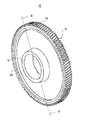
- FIG. 1 is a perspective view illustrating a correction gear according to the present embodiment.
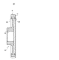
- FIG. 2A is a perspective view illustrating a correction gear according to the present embodiment.
- FIG. 2B is a longitudinal sectional view illustrating the correction gear according to the present embodiment. It is the schematic which shows an example of the cylindrical body and axial body used for OBD calculation by a model. It is a graph which shows an example of the relation between the interference and the OBD increase. It is a flowchart which shows the procedure of the gear correction method concerning this embodiment.
- FIG. 1 is a perspective view illustrating a correction gear according to the present embodiment.
- the correction gear 15 includes the gear 10 and an annular inner ring 20.
- the correction gear 15 is formed by press-fitting an annular inner ring 20 into the gear 10.
- this figure shows a state before the inner ring 20 is press-fitted into the gear 10.
- the gear 10 is, for example, an engine timing gear, and has an inner peripheral surface 12 and an outer peripheral surface 16 (see FIG. 2B) on which a tooth profile 14 is formed.
- the outer peripheral surface 16 is a peripheral surface corresponding to the tooth bottom of the tooth profile 14 and is formed concentrically with the inner peripheral surface 12 and has a larger diameter than the inner peripheral surface 12.
- the inner peripheral surface 12 of the gear 10 is formed separately from the rotating shaft housing surface 18 in which the rotating shaft (not shown) of the gear 10 is housed, but is not limited to this shape.
- the shaft receiving surface 18 may be the same surface as the inner peripheral surface 12.
- two inner rings 20, 20 are press-fitted into the inner peripheral surface 12 of the gear 10 from both sides of the gear 10.
- the outer diameter of the inner ring 20 is formed to be larger than the diameter of the inner peripheral surface 12 of the gear 10.
- the material of the gear 10 and the material of the inner ring 20 are not particularly limited, and they may be the same material or different materials. However, if the easiness of deformation (for example, Young's modulus) of the two is largely different, it becomes difficult to integrate them during press-fitting, which is not preferable. Therefore, it is preferable to use a steel material having similar Young's modulus for both.
- FIG. 2A is a perspective view illustrating a correction gear according to the present embodiment.
- FIG. 2B is a longitudinal sectional view illustrating the correction gear according to the present embodiment.
- FIG. 2 shows a state after the inner ring 20 is press-fitted into the gear 10.
- FIG. 2B is a sectional view taken along line BB of FIG. 2A.
- the following method can be considered for press-fitting the inner ring 20 having an outer diameter larger than the inner diameter into the inner peripheral surface 12 of the gear 10.
- This simple press-fitting method can be easily performed, but if the difference between the diameter of the inner peripheral surface 12 of the gear 10 and the outer diameter of the inner ring 20 increases, it becomes difficult to press-fit the gear 10 and there is a concern that the gear 10 may be damaged. .
- the gear 10 is heated at a predetermined temperature to make the diameter of the inner peripheral surface 12 larger than the outer diameter of the inner ring 20, and then the inner ring 20 is inserted into the inner peripheral surface 12 and cooled.
- the gear 10 By expanding the gear 10 by heating and making the diameter of the inner peripheral surface 12 larger than the outer diameter of the inner ring 20, the gear 10 can be easily inserted into the inner peripheral surface 12 without applying force to the inner ring 20. After the inner ring 20 is inserted, the gear 10 contracts by being cooled by being cooled by the inner ring 20 while being pushed outward in the circumferential direction. Therefore, the inner ring 20 fits into the gear 10 and is integrated and fixed.
- the temperature at which the gear 10 is heated can be set after determining the amount of expansion in the radial direction in consideration of the coefficient of thermal expansion of the material used for the gear 10.
- This method requires a heating device, but has an advantage that the inner ring 20 can be easily inserted into the gear 10 and the possibility that the gear 10 is damaged is small.
- the gear 10 is pushed and spread radially outward from the inside of the gear 10 after press-fitting. Further, in the above press-fitting method, the gear 10 is symmetrically pushed and spread by press-fitting the two inner rings 20 from both sides of the gear 10, but depending on the shape of the gear 10, only one of the inner rings 20 is used alone. Can be press-fitted. Thus, the correction gear 15 in which the diameter of the outer peripheral surface 16 of the gear 10 is corrected in the radial direction can be manufactured.
- FIG. 3 is a schematic view showing an example of a tubular body and a shaft body used for OBD calculation by a model.
- a circular pipe 30 having an ideal circular pipe shape and an inner diameter of D1 is assumed to correspond to the gear 10.
- a shaft body 40 having an ideal cylindrical shape and an outer diameter of D2 corresponding to the inner ring 20 was assumed.
- the outer diameter D2 of the shaft body 40 on the insertion side is larger than the inner diameter D1 of the cylindrical body 30 on the insertion side, that is, D2> D1
- D2 and D1 (D2 ⁇ D1) is defined as “offset”.
- the values of the Young's modulus, Poisson's ratio, inner diameter D1, and outer diameter of the tubular body 30 are set in consideration of the material and dimensions of the gear 10 to be used, and the material and dimensions of the inner ring 20 to be used In consideration of the above, values such as the Young's modulus, the outer diameter D2, and the insertion length of the shaft body 40 are set. Further, in an ideal state, when the tubular body 30 is pushed out from the inside of the tubular body 30 with a predetermined interference by the shaft body 40, a numerical calculation of how much the outer diameter of the tubular body 30 expands is performed. Was. FIG. 4 shows the result of this numerical calculation.
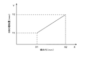
- FIG. 4 is a graph showing an example of the relationship between the interference and the OBD increase amount. According to the result of FIG. 4, when the value of the interference (mm) increases, the value of the OBD increase amount (mm) increases linearly.
- the OBD increase amount (mm) when the interference (mm) is X1 is the OBD minimum increase amount Y1
- the OBD increase amount (mm) when the interference (mm) is X2 is the OBD maximum increase amount Y2.
- the OBD calculation by the model is performed using the numerical values corresponding to the gear 10 and the inner ring 20 described above.
- the OBD minimum increase Y1 is +0.019 mm
- the OBD The maximum increase Y2 is +0.051 mm.
- the OBD shift value is, for example, 0 mm to ⁇ 0.07 mm due to the variation in manufacturing conditions, and has a predetermined width on the negative side.
- the “OBD deviation value” refers to a deviation value of the OBD measurement value from the set OBD target value, and the “negative side” means that the OBD measurement value is smaller than the OBD reference value. .
- the OBD maximum increase amount due to the press-fit deformation is determined in advance by the OBD calculation using the model, and the OBD maximum increase amount is set to a value smaller than the negative value. Also, press-fitting is performed on a gear whose OBD shift value is further on the negative side. Then, the OBD shift value is moved to the positive side by increasing the OBD to the positive side by the amount of the OBD increase by press-fitting, thereby reducing the variation of the OBD.
- the OBD maximum increase amount Y2 due to press-fit deformation is determined in advance by OBD calculation using a model.
- the OBD maximum increase amount Y2 (+0.051 mm) is determined in advance.
- a range in which the OBD shift value is further on the negative side ie, from -0.07 mm to -0.051 mm (however,-)) is smaller than the value (-0.051 mm) obtained by making the OBD maximum increase amount Y2 (+0.051 mm) negative.
- the inner ring 20 is pressed into the gear 10 (not including 0.051 mm) to move (increase) the OBD shift value to the positive side.
- the gear correction according to the present embodiment using the OBD calculation based on the model will be described below. The method will be described.
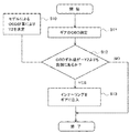
- FIG. 5 is a flowchart illustrating a procedure of the gear correction method according to the present embodiment.
- the OBD calculation is performed in advance using the above-described model based on the characteristics of the gear 10 and the inner ring 20, and the OBD maximum increase amount Y2 is determined (step S10).
- OBD can be measured by a known measuring method.
- step S12 it is determined whether or not the OBD shift value is on the negative side of ⁇ Y2 (step S12). If it is on the more negative side than -Y2 (YES in step S12), the inner ring 20 is pressed into the gear 10 (step S13). On the other hand, when it is not on the more negative side than -Y2 (NO in step S12), the inner ring 20 is not pressed into the gear 10 and the process is terminated as it is.
- the OBD of the gear 10 is increased by 0.019 mm to 0.051 mm by press-fitting the inner ring 20 in the above-mentioned interference range of 0.040 mm to 0.100 mm. Therefore, in the plurality of gears 10 having the OBD shift value in the range of 0 mm to -0.07 mm, not all the gears 10 but only the gear 10 whose OBD shift value is more negative than -0.051 mm. Verify the effect of press-fitting.
- the OBD when the OBD deviation value is ⁇ 0.07 mm (when the deviation from the target value is the largest when press-fitting), the OBD is set to 0.019 mm to 0 mm by press-fitting the inner ring 20 within the above-mentioned interference range. It moves (increases) to the positive side of 0.051 mm, and the width of the OBD shift value becomes ⁇ 0.051 mm to ⁇ 0.019 mm.
- the OBD deviation value is ⁇ 0.051 mm (the case where the deviation from the target value in the case of press fitting is the smallest) will be described.
- press-fitting is performed when the OBD shift value is on the more negative side than -0.051 mm. Strictly speaking, press-fitting is not performed when the OBD shift value is -0.051 mm. explain. Due to the press-fitting, the width of the OBD shift value moves (increases) to the positive side by 0.019 mm to 0.051 mm, and the width of the OBD shift value becomes -0.032 mm to 0 mm.
- the interference is adjusted within the range of 0.040 mm to 0.100 mm and the press-fit is performed.
- the width of the OBD shift value can be arbitrarily corrected within the range of -0.051 mm to 0 mm.
- the OBD shift value of the gear 10 is not more negative than ⁇ 0.051 mm, that is, when the width of the OBD shift value is ⁇ 0.051 mm to 0 mm, the OBD shift value is originally small, and the OBD shift due to press-fitting is small. Since the value range is within the reduction range, the press-fitting process can be omitted, so that the work efficiency can be improved.
- the gear correction method using the OBD calculation based on the model it is possible to finally reduce the width of the OBD shift value to a range of 0 mm to ⁇ 0.051 mm. That is, with the gear 10 alone, the width of the OBD shift value from 70 ⁇ m can be reduced to 51 ⁇ m by press-fitting the inner ring 20. Therefore, variation in the OBD of the gear 10 can be reduced.
- the correction gear 15 includes a gear 10 having an inner peripheral surface 12 and an outer peripheral surface 16 on which a tooth profile 14 is formed, and an inner ring 20 that is press-fit into the inner peripheral surface 12 of the gear 10. For this reason, the gear 10 can be corrected in the radial direction by the press-fitting deformation, whereby the variation of the OBD can be reduced.
- the gear 10 is heated at a predetermined temperature by using an annular inner ring 20 having an outer diameter larger than the diameter of the inner peripheral surface 12 so that the diameter of the inner peripheral surface 12 is larger than the outer diameter of the inner ring 20. Thereafter, the inner ring 20 is inserted into the inner peripheral surface 12 and cooled, so that the inner ring 20 can be easily inserted into the gear 10. Further, the possibility that the gear 10 is damaged can be reduced.
- the OBD maximum increase amount due to press-fitting deformation is determined in advance by OBD calculation using a model, and the OBD maximum value is determined.
- the inner ring 20 is press-fitted into the gear 10 in which the OBD shift value is further on the negative side than the value in which the increase amount is negative. For this reason, variation in OBD can be reduced, and work efficiency can be reduced.
- the variation of the gear backlash can be reduced by press-fitting the inner ring 20 and adjusting the OBD to reduce the variation. For this reason, gear rattle noise can be reduced, which leads to noise reduction.
- the example of the timing gear of the engine is shown as the gear 10, but the shape of the gear 10 is not particularly limited, and not only a simple annular spur gear, but also a helical gear, It may be a bevel gear, a spiral bevel gear, a screw gear, a miter gear, or the like.
- annular inner ring 20 is press-fitted
- it may be a polygonal annular body as well as an annular shape.
- a shaft, a column, or the like can be press-fitted in consideration of the shape, function, and the like of the gear 10.
- correction gear and the method of correcting the gear according to the present disclosure are useful in that the variation in the OBD of the gear can be reduced.
Landscapes
- Engineering & Computer Science (AREA)
- General Engineering & Computer Science (AREA)
- Mechanical Engineering (AREA)
- Gears, Cams (AREA)
Abstract
内周面(12)と歯形(14)が形成された外周面(16)と、を有するギア(10)に対して、内周面(12)にインナーリング(20)を圧入し、ギア(10)の外周面(16)の径を径方向に補正する。
Description
本開示は、補正ギア及びギアの補正方法に関する。
ギアの大きさを管理する指標として、OBD(Over Ball Diameter)がある。OBDは、ギアの直径の両端に位置する歯溝に置いた2個のボール越しに計った距離である(例えば、特許文献1参照)。
ギアは、一般的に、所定の形状を有する原材料から歯切加工され、更に焼入れ・焼戻し等の熱処理が施されて製造される。このため、製造条件のばらつき等により、歯形の形状や寸法等にずれが生じてOBDがばらつくことがあった。従って、ギア単独でOBDのばらつきを小さくするには限界があった。
本開示の技術は、ギアのOBDのばらつきを低減することを目的とする。
本開示の技術は、内周面と歯形が形成された外周面とを有するギアと、前記ギアの前記内周面に圧入されることにより、前記ギアの前記外周面の径を径方向に補正する挿入物とを備える補正ギアである。
前記挿入物は、前記内周面の径よりも大きな外径を有する円環状のインナーリングであることが好ましい。
また、本開示の技術は、内周面と歯形が形成された外周面とを有するギアの前記内周面に対して、前記内周面の径よりも大きな外径を有する円環状のインナーリングを圧入し、前記ギアの前記外周面の径を径方向に補正するギアの補正方法である。
前記圧入は、前記ギアを所定温度で加熱して前記内周面の径を前記インナーリングの外径よりも大きくした後、前記内周面に前記インナーリングを挿入し、冷却することが好ましい。
また、設定されたOBD目標値からのOBD測定値のずれの値であるOBDずれ値が負である複数のギアがある場合に、モデルによるOBD計算によって圧入変形によるOBD最大増加量を予め決定しておき、前記OBD最大増加量を負にした値よりも前記OBDずれ値がさらに負側にあるギアに対して、前記圧入を行うことが好ましい。
本開示の技術によれば、ギアのOBDのばらつきを低減することができる。
以下、添付図面に基づいて、本実施形態に係る補正ギア及びギアの補正方法について説明する。同一の部品には同一の符号を付してあり、それらの名称および機能も同じである。したがって、それらについての詳細な説明は繰返さない。
(補正ギア15)
図1は、本実施形態に係る補正ギアを説明する斜視図である。
図1は、本実施形態に係る補正ギアを説明する斜視図である。
補正ギア15は、ギア10と、円環状のインナーリング20を備える。補正ギア15は、ギア10の内部に円環状のインナーリング20が圧入されることによって形成される。ここで、本図では、ギア10にインナーリング20が圧入される前の状態を示している。
ギア10は、例えばエンジンのタイミングギアであり、内周面12と、歯形14が形成された外周面16(図2B参照)とを有している。外周面16は、歯形14の歯底に対応した周面であり、内周面12と同心円状で、かつ、内周面12よりも大径に形成されている。
なお、本実施形態において、ギア10の内周面12は、ギア10の回転軸(不図示)が収容される回転軸収容面18とは別に形成されているが、この形状には限定されず、軸収容面18が内周面12と同一の面であってもよい。
本実施形態の補正ギア15では、ギア10の両側からギア10の内周面12に、2つのインナーリング20,20が圧入される。ここで、インナーリング20の外径は、ギア10の内周面12の径よりも大きく形成されている。
ギア10の材質とインナーリング20の材質は特に限定されず、両者が同じ材料であっても異なる材料であっても構わない。ただし、両者の変形のし易さ(例えば、ヤング率)が大きく相違していると圧入の際一体化が困難になり好ましくない。よって、両者には、ヤング率が近似した鉄鋼材料を用いることが好ましい。
図2Aは、本実施形態に係る補正ギアを説明する斜視図である。図2Bは、本実施形態に係る補正ギアを説明する縦断面図である。本図では、ギア10にインナーリング20が圧入された後の状態を示している。なお、図2Bは、図2AのB-B線断面図である。
ギア10の内周面12に、その内径よりも大きな外径を有するインナーリング20を圧入するには、以下の方法が考えられる。
まず、常温の状態でギア10に対してインナーリング20を圧入方向に力を加えながら挿入する方法(以下、「単純圧入方法」と記す)がある。この単純圧入方法は、簡便に行うことができるが、ギア10の内周面12の径とインナーリング20の外径との差分が大きくなると圧入し難くなり、またギア10が破損する懸念もある。
次に、別の圧入方法としての「焼き嵌め方法」について説明する。
この方法は、ギア10を所定温度で加熱して内周面12の径をインナーリング20の外径よりも大きくした後、内周面12にインナーリング20を挿入し、冷却する方法である。
ギア10を加熱により膨張させ、内周面12の径をインナーリング20の外径よりも大きくすることによって、インナーリング20に力を加えることなく、内周面12に平易に挿入できる。インナーリング20の挿入後は、冷却することにより、ギア10がインナーリング20によって周方向外側に向かってに押し広げられたままの状態で収縮する。従って、インナーリング20がギア10に嵌り、一体化されて固定されることになる。
ギア10を加熱する温度については、ギア10に用いられる材質の熱膨張係数を考慮し、径方向への拡大量を決定した上で設定することができる。
この方法では、加熱装置が必要となるが、平易にインナーリング20をギア10に挿入することができ、またギア10が破損する可能性も小さいという利点がある。
上述したいずれの圧入方法においても、圧入後にギア10の内側から径方向外側に向かって押し広げられていればよい。また、上記圧入方法では、ギア10の両側から2つのインナーリング20を圧入することにより対称的にギア10を押し広げているが、ギア10の形状に応じて、どちらか一方の側からのみ単独のインナーリング20を圧入することもできる。このようにして、ギア10の外周面16の径が径方向に補正された補正ギア15を製造することができる。
次に、本実施形態に係るギアの補正方法を説明する前に、その前提となるモデルによるOBD計算方法について説明する。
(モデルによるOBD計算方法)
図3は、モデルによるOBD計算に用いる円管体と軸体の一例を示す概略図である。
図3は、モデルによるOBD計算に用いる円管体と軸体の一例を示す概略図である。
本実施形態では、モデルによるOBD計算に際し、ギア10に対応させて理想的な円管形状でD1の内径を有する円管体30を想定した。また、インナーリング20に対応させて理想的な円柱形状でD2の外径を有する軸体40を想定した。ここで、挿入される側の円管体30の内径D1よりも、挿入する側の軸体40の外径D2の方が大きいと仮定する、即ち、D2>D1の関係にあり、D2とD1との差分(D2-D1)を「締め代」と定義する。
モデルによるOBD計算では、使用するギア10の材質、寸法等を考慮して円管体30のヤング率、ポアソン比、内径D1、外径の値を設定し、使用するインナーリング20の材質、寸法等を考慮して、軸体40のヤング率、外径D2、挿入長さ等の値を設定した。さらに、理想的な状態で円管体30の内側から軸体40により所定の締め代で円管体30を押し広げた時に、円管体30の外径がどれだけ広がるかの数値計算を行った。この数値計算の結果を図4に示す。
図4は、締め代とOBD増加量との関係の一例を示すグラフである。図4の結果より、締め代(mm)の値が増加すると、OBD増加量(mm)の値は、直線的に増加している。
ここで、締め代(mm)がX1の時のOBD増加量(mm)をOBD最小増加量Y1、締め代(mm)がX2の時のOBD増加量(mm)をOBD最大増加量Y2とする。
例えば、X1を0.040mm、X2を0.100mmとし、上述したギア10及びインナーリング20に相当する数値を用いてモデルによるOBD計算を行った結果、OBD最小増加量Y1は+0.019mm、OBD最大増加量Y2は+0.051mmとなる。
他方、ギア10単独の場合、製造条件のばらつきによって、OBDずれ値は、例えば、0mm~-0.07mmとなり、負側に所定の幅を有する。ここで、「OBDずれ値」とは、設定されたOBD目標値からのOBD測定値のずれの値をいい、「負側」とは、OBD測定値がOBD基準値よりも小さいことを意味する。
本実施形態では、OBDずれ値が負である複数のギア10がある場合に、モデルによるOBD計算によって圧入変形によるOBD最大増加量を予め決定しておき、OBD最大増加量を負にした値よりもOBDずれ値がさらに負側にあるギアに対して、圧入を行う。そして、圧入によりOBD増加量の分だけ正側にOBDを増加させることによってOBDずれ値を正側に移動させてOBDのばらつきを低減する。
上記例で具体的に説明すると、ギア10が負側に所定のOBDずれ値の幅(0mm~-0.07mm)を有する場合に、モデルによるOBD計算によって圧入変形によるOBD最大増加量Y2を予め決定しておき、OBD最大増加量Y2(+0.051mm)とする。このOBD最大増加量Y2(+0.051mm)を負にした値(-0.051mm)よりもOBDずれ値がさらに負側にある範囲(即ち、-0.07mm~-0.051mm(ただし、-0.051mmは含まず)のギア10について、インナーリング20を圧入して、OBDずれ値を正側に移動(増加)させる。以下、モデルによるOBD計算を用いた本実施形態に係るギアの補正方法について説明する。
(ギアの補正方法)
図5は、本実施形態に係るギアの補正方法の手順を示すフローチャートである。本方法では、予め、ギア10及びインナーリング20の特性に基づいた上述のモデルによりOBD計算を行っておき、OBD最大増加量Y2を決定しておく(ステップS10)。
図5は、本実施形態に係るギアの補正方法の手順を示すフローチャートである。本方法では、予め、ギア10及びインナーリング20の特性に基づいた上述のモデルによりOBD計算を行っておき、OBD最大増加量Y2を決定しておく(ステップS10)。
次に、ギア10のOBDを測定し、OBDずれ値を求める(ステップS11)。OBDの測定は、公知の測定方法によって行うことができる。
さらに、OBDずれ値が-Y2よりも負側にあるか否かを判定する(ステップS12)。-Y2よりも負側にある場合(ステップS12でYES)は、インナーリング20をギア10に圧入する(ステップS13)。他方、-Y2よりも負側にない場合(ステップS12でNO)は、インナーリング20をギア10に圧入せず、そのまま終了する。
モデルによるOBD計算によれば、インナーリング20を上記締め代0.040mm~0.100mmの範囲で圧入することによって、ギア10のOBDは0.019mm~0.051mm増加する。このため、OBDずれ値が0mm~-0.07mmの範囲にある複数のギア10において、すべてのギア10ではなく、OBDずれ値が-0.051mmよりも負側にあるギア10に対してのみ圧入を行った場合の効果について検証する。
まず、OBDずれ値が-0.07mmの場合(圧入する場合で目標値からのずれが最大の場合)は、インナーリング20を上記締め代の範囲で圧入することによりOBDが0.019mm~0.051mm正側に移動(増加)し、OBDずれ値の幅は-0.051mm~-0.019mmとなる。
次に、OBDずれ値が-0.051mmの場合(圧入する場合で目標値からのずれが最小の場合)について説明する。なお、本実施形態では、OBDずれ値が-0.051mmよりも負側にある場合に圧入を行うので、厳密にはOBDずれ値が-0.051mmの場合には圧入を行わないが、便宜上説明する。上記圧入によりOBDずれ値の幅が0.019mm~0.051mm正側に移動(増加)し、OBDずれ値の幅は-0.032mm~0mmとなる。
即ち、ギア10のOBDずれ値が-0.051mmよりも負側にある場合に、上記締め代0.040mm~0.100mmの範囲内で締め代を調整して圧入することによって、ギア10のOBDずれ値の幅を-0.051mm~0mmの範囲で任意に補正できることになる。
他方、ギア10のOBDずれ値が-0.051mmよりも負側にない場合、即ち、OBDずれ値の幅が-0.051mm~0mmの場合は、元々OBDずれ値が小さく、圧入によるOBDずれ値の幅の低減範囲内にあるため、圧入処理を省略化することにより、作業の効率化を図ることができる。
以上説明したように、モデルによるOBD計算を用いたギアの補正方法によれば、最終的にOBDずれ値の幅を0mm~-0.051mmの範囲に縮めることが可能になる。即ち、ギア10単独では、70μmだったOBDずれ値の幅をインナーリング20の圧入によって51μmまで低減できることになる。従って、ギア10のOBDのばらつきを低減することができる。
(本実施形態の効果)
本実施形態に係る補正ギア15は、内周面12と歯形14が形成された外周面16とを有するギア10と、ギア10の内周面12に圧入されるインナーリング20とを備える。このため、圧入変形によってギア10を径方向に補正することができ、これによって、OBDのばらつきを低減することができる。
本実施形態に係る補正ギア15は、内周面12と歯形14が形成された外周面16とを有するギア10と、ギア10の内周面12に圧入されるインナーリング20とを備える。このため、圧入変形によってギア10を径方向に補正することができ、これによって、OBDのばらつきを低減することができる。
また、内周面12の径よりも大きな外径を有する円環状のインナーリング20を用い、ギア10を所定温度で加熱して内周面12の径をインナーリング20の外径よりも大きくした後、内周面12にインナーリング20を挿入し、冷却することにより、平易にインナーリング20をギア10に挿入することができる。また、ギア10が破損する可能性も低減できる。
さらに、本実施形態に係るギアの補正方法では、OBDずれ値が負である複数のギア10がある場合に、モデルによるOBD計算によって圧入変形によるOBD最大増加量を予め決定しておき、OBD最大増加量を負にした値よりもOBDずれ値がさらに負側にあるギア10に対して、インナーリング20の圧入を行う。このため、OBDのばらつきを低減することができると共に、作業効率を低減することができる。
以上説明したように、インナーリング20を圧入し、OBDを調整してばらつきを低減することにより、ギアバックラッシュのバラつきを低減できる。このため、ギア歯打ち(ラトル)音を低減でき、騒音低減にもつながる。
(他の実施形態)
以上、本開示の実施形態を説明したが、この実施形態は、例として提示したものであり、発明の範囲を限定することは意図していない。この実施形態は、その他の様々な形態で実施されることが可能であり、本開示の要旨を逸脱しない範囲で、種々の省略、置き換え、変更を行うことができる。この実施形態やその変形は、発明の範囲や要旨に含まれると同様に、特許請求の範囲に記載された発明とその均等の範囲に含まれるものである。
以上、本開示の実施形態を説明したが、この実施形態は、例として提示したものであり、発明の範囲を限定することは意図していない。この実施形態は、その他の様々な形態で実施されることが可能であり、本開示の要旨を逸脱しない範囲で、種々の省略、置き換え、変更を行うことができる。この実施形態やその変形は、発明の範囲や要旨に含まれると同様に、特許請求の範囲に記載された発明とその均等の範囲に含まれるものである。
例えば、上記実施形態では、ギア10として、エンジンのタイミングギアの例を示したが、ギア10の形状には特に制約されず、単純な円環形状の平歯車だけでなく、はすば歯車、かさ歯車、まがりばかさ歯車、ねじ歯車、マイタ歯車等であってもよい。
また、上記実施形態では、円環状のインナーリング20を圧入する例を示したが、円環状だけでなく、多角形状の環状体であってもよい。さらに、ギア10の形状や機能等を考慮して、軸や円柱等を圧入することもできる。
本出願は、2018年09月28日付で出願された日本国特許出願(特願2018-183445)に基づくものであり、その内容はここに参照として取り込まれる。
本開示の補正ギア及びギアの補正方法は、ギアのOBDのばらつきを低減することができるという点において有用である。
10 ギア
12 内周面
14 歯形
15 補正ギア
16 外周面
20 インナーリング(挿入物)
30 円管体
40 軸体
12 内周面
14 歯形
15 補正ギア
16 外周面
20 インナーリング(挿入物)
30 円管体
40 軸体
Claims (5)
- 内周面と歯形が形成された外周面とを有するギアと、
前記ギアの前記内周面に圧入されることにより、前記ギアの前記外周面の径を径方向に補正する挿入物とを備える、補正ギア。 - 前記挿入物は、前記内周面の径よりも大きな外径を有する円環状のインナーリングである請求項1に記載の補正ギア。
- 内周面と歯形が形成された外周面とを有するギアの前記内周面に対して、前記内周面の径よりも大きな外径を有する円環状のインナーリングを圧入し、前記ギアの前記外周面の径を径方向に補正するギアの補正方法。
- 前記圧入は、前記ギアを所定温度で加熱して前記内周面の径を前記インナーリングの外径よりも大きくした後、前記内周面に前記インナーリングを挿入し、冷却する請求項3に記載のギアの補正方法。
- 設定されたOBD目標値からのOBD測定値のずれの値であるOBDずれ値が負である複数のギアがある場合に、モデルによるOBD計算によって圧入変形によるOBD最大増加量を予め決定しておき、前記OBD最大増加量を負にした値よりも前記OBDずれ値がさらに負側にあるギアに対して、前記圧入を行う請求項3又は4に記載のギアの補正方法。
Priority Applications (3)
| Application Number | Priority Date | Filing Date | Title |
|---|---|---|---|
| US17/280,389 US12044300B2 (en) | 2018-09-28 | 2019-09-25 | Corrected gear and method for correcting gear |
| DE112019004846.5T DE112019004846T5 (de) | 2018-09-28 | 2019-09-25 | Korrigiertes zahnrad und zahnradkorrekturverfahren |
| CN201980064119.6A CN112771288B (zh) | 2018-09-28 | 2019-09-25 | 修正齿轮及齿轮的修正方法 |
Applications Claiming Priority (2)
| Application Number | Priority Date | Filing Date | Title |
|---|---|---|---|
| JP2018-183445 | 2018-09-28 | ||
| JP2018183445A JP2020051568A (ja) | 2018-09-28 | 2018-09-28 | 補正ギア及びギアの補正方法 |
Publications (1)
| Publication Number | Publication Date |
|---|---|
| WO2020067091A1 true WO2020067091A1 (ja) | 2020-04-02 |
Family
ID=69950167
Family Applications (1)
| Application Number | Title | Priority Date | Filing Date |
|---|---|---|---|
| PCT/JP2019/037458 Ceased WO2020067091A1 (ja) | 2018-09-28 | 2019-09-25 | 補正ギア及びギアの補正方法 |
Country Status (5)
| Country | Link |
|---|---|
| US (1) | US12044300B2 (ja) |
| JP (1) | JP2020051568A (ja) |
| CN (1) | CN112771288B (ja) |
| DE (1) | DE112019004846T5 (ja) |
| WO (1) | WO2020067091A1 (ja) |
Citations (2)
| Publication number | Priority date | Publication date | Assignee | Title |
|---|---|---|---|---|
| JP2002235836A (ja) * | 2001-02-09 | 2002-08-23 | Aisin Aw Co Ltd | 制振歯車 |
| WO2011080824A1 (ja) * | 2009-12-28 | 2011-07-07 | トヨタ自動車 株式会社 | ギアプレート |
Family Cites Families (14)
| Publication number | Priority date | Publication date | Assignee | Title |
|---|---|---|---|---|
| US1852538A (en) | 1929-10-11 | 1932-04-05 | Westinghouse Electric & Mfg Co | Damping means for gear wheels |
| GB2185801A (en) | 1986-01-27 | 1987-07-29 | Smidth & Co As F L | Rotatable drum assembly |
| JP2001269815A (ja) * | 2000-03-27 | 2001-10-02 | Nissan Motor Co Ltd | 歯車の研削加工装置およびその方法 |
| JP2006088762A (ja) | 2004-09-21 | 2006-04-06 | Jtekt Corp | 電動パワーステアリング装置 |
| US20070277644A1 (en) * | 2006-06-06 | 2007-12-06 | King Anthony W | Flex Plate with Welded Rim |
| US20070277643A1 (en) * | 2006-06-06 | 2007-12-06 | King Anthony W | Flex Plate with Attached Rim |
| JP5275150B2 (ja) | 2009-06-23 | 2013-08-28 | 株式会社ハーモニック・ドライブ・システムズ | 波動歯車装置 |
| US9982748B2 (en) * | 2012-12-12 | 2018-05-29 | Magna International | Flexplates and method for capacitor discharge welding of flexplates |
| WO2015097919A1 (ja) | 2013-12-27 | 2015-07-02 | 株式会社 東京テクニカル | オーバーボール径測定装置 |
| JP6440452B2 (ja) * | 2014-10-28 | 2018-12-19 | トーヨーエイテック株式会社 | 歯車研削盤の加工精度修正方法 |
| US20160319903A1 (en) * | 2015-04-29 | 2016-11-03 | Schaeffler Technologies AG & Co. KG | Interlock for ring gear on a flywheel |
| KR102341383B1 (ko) * | 2015-12-31 | 2021-12-20 | 남양넥스모 주식회사 | 댐핑 기어휠 구조체 |
| US11173568B2 (en) * | 2018-07-11 | 2021-11-16 | GM Global Technology Operations LLC | Composite metal flexplate |
| US11359708B2 (en) * | 2019-08-19 | 2022-06-14 | Schaeffler Technologies AG & Co. KG | Flexplate for connecting damper assembly to an internal combustion engine crankshaft |
-
2018
- 2018-09-28 JP JP2018183445A patent/JP2020051568A/ja active Pending
-
2019
- 2019-09-25 US US17/280,389 patent/US12044300B2/en active Active
- 2019-09-25 CN CN201980064119.6A patent/CN112771288B/zh active Active
- 2019-09-25 WO PCT/JP2019/037458 patent/WO2020067091A1/ja not_active Ceased
- 2019-09-25 DE DE112019004846.5T patent/DE112019004846T5/de active Pending
Patent Citations (2)
| Publication number | Priority date | Publication date | Assignee | Title |
|---|---|---|---|---|
| JP2002235836A (ja) * | 2001-02-09 | 2002-08-23 | Aisin Aw Co Ltd | 制振歯車 |
| WO2011080824A1 (ja) * | 2009-12-28 | 2011-07-07 | トヨタ自動車 株式会社 | ギアプレート |
Also Published As
| Publication number | Publication date |
|---|---|
| US12044300B2 (en) | 2024-07-23 |
| CN112771288A (zh) | 2021-05-07 |
| US20220034393A1 (en) | 2022-02-03 |
| JP2020051568A (ja) | 2020-04-02 |
| CN112771288B (zh) | 2024-05-07 |
| DE112019004846T5 (de) | 2021-06-17 |
Similar Documents
| Publication | Publication Date | Title |
|---|---|---|
| US9903365B2 (en) | Structure for fixing shaft member in rotor member for fluid pump | |
| KR101838929B1 (ko) | 파동발생기 및 파동기어장치 | |
| JP5093003B2 (ja) | スプラインシャフト、及び、スプラインシャフトの製造方法 | |
| CN104769314A (zh) | 行星齿轮装置 | |
| JP2017025964A5 (ja) | ||
| CN104712731A (zh) | 偏心摆动型减速装置及其偏心体轴齿轮的制造方法 | |
| US20190072172A1 (en) | Harmonic drive | |
| US9964180B2 (en) | Gearing having a pinion and a wheel | |
| JP2020051568A (ja) | 補正ギア及びギアの補正方法 | |
| JP5170323B2 (ja) | ギアプレート | |
| CN105790519A (zh) | 马达轴、马达以及马达结构体 | |
| JP5969615B2 (ja) | 結合構造およびスプライン結合体の製造方法 | |
| JP2003278738A (ja) | 伸縮軸及び伸縮軸のコーティング層形成方法 | |
| JP4825749B2 (ja) | 回転部材の固定構造 | |
| TW201608151A (zh) | 滾珠螺桿裝置及其製造方法 | |
| US20160273638A1 (en) | Method of attaching ring gear to differential case, jig, and differential case | |
| JP2010043733A (ja) | プーリ付き転がり軸受装置 | |
| JP2016501331A (ja) | カム軸 | |
| JP2012081789A (ja) | ステアリングシャフト | |
| JP2017221974A (ja) | 同期式手動変速機アセンブリのためのスライド式スリーブの製造方法および該方法によって製造されたスライド式スリーブ | |
| JP4853776B2 (ja) | Cvt用シャフト及びその製造方法 | |
| JP2018197601A (ja) | 固定方法及び固定構造 | |
| JP2015124787A (ja) | 転がり軸受用内輪の固定方法及び転がり軸受用内輪の固定構造物 | |
| JPH084717A (ja) | 圧入工作物及びその製造方法 | |
| JP4877446B2 (ja) | 塑性流動締結方法及び塑性流動締結構造 |
Legal Events
| Date | Code | Title | Description |
|---|---|---|---|
| 121 | Ep: the epo has been informed by wipo that ep was designated in this application |
Ref document number: 19865618 Country of ref document: EP Kind code of ref document: A1 |
|
| WWE | Wipo information: entry into national phase |
Ref document number: 2101001719 Country of ref document: TH |
|
| 122 | Ep: pct application non-entry in european phase |
Ref document number: 19865618 Country of ref document: EP Kind code of ref document: A1 |