US1852538A - Damping means for gear wheels - Google Patents
Damping means for gear wheels Download PDFInfo
- Publication number
- US1852538A US1852538A US398988A US39898829A US1852538A US 1852538 A US1852538 A US 1852538A US 398988 A US398988 A US 398988A US 39898829 A US39898829 A US 39898829A US 1852538 A US1852538 A US 1852538A
- Authority
- US
- United States
- Prior art keywords
- rim
- gear
- wheel
- ring
- gear wheels
- Prior art date
- Legal status (The legal status is an assumption and is not a legal conclusion. Google has not performed a legal analysis and makes no representation as to the accuracy of the status listed.)
- Expired - Lifetime
Links
Images
Classifications
-
- F—MECHANICAL ENGINEERING; LIGHTING; HEATING; WEAPONS; BLASTING
- F16—ENGINEERING ELEMENTS AND UNITS; GENERAL MEASURES FOR PRODUCING AND MAINTAINING EFFECTIVE FUNCTIONING OF MACHINES OR INSTALLATIONS; THERMAL INSULATION IN GENERAL
- F16H—GEARING
- F16H55/00—Elements with teeth or friction surfaces for conveying motion; Worms, pulleys or sheaves for gearing mechanisms
- F16H55/02—Toothed members; Worms
- F16H55/14—Construction providing resilience or vibration-damping
-
- Y—GENERAL TAGGING OF NEW TECHNOLOGICAL DEVELOPMENTS; GENERAL TAGGING OF CROSS-SECTIONAL TECHNOLOGIES SPANNING OVER SEVERAL SECTIONS OF THE IPC; TECHNICAL SUBJECTS COVERED BY FORMER USPC CROSS-REFERENCE ART COLLECTIONS [XRACs] AND DIGESTS
- Y10—TECHNICAL SUBJECTS COVERED BY FORMER USPC
- Y10T—TECHNICAL SUBJECTS COVERED BY FORMER US CLASSIFICATION
- Y10T74/00—Machine element or mechanism
- Y10T74/19—Gearing
- Y10T74/1987—Rotary bodies
- Y10T74/19893—Sectional
- Y10T74/19907—Sound deadening
Definitions
- My invention relates, in general, to silencing devices and, in particular, to means for preventing ringing of wheels, such as gear wheels.
- An object of the invention is, generally stated, to provide simple and inexpensive means for preventing ringing of gear wheels.
- Another object of the invention is to provide a damping device, for absorbing the vibrations of a wheel rim, that shall be of rugged construction and not liable to be damaged when the wheel to which it is applied is utilized on machinery which is subjected to J violent vibrations.
- a further object of the invention is to provide a sound-deadening device for gear wheels that may be readily applied during the process of manufacturing a wheel without requiring expensive machine work either on the wheel or on the sound-deadening device.
- Fig. 2 is a view, in longitudinal section, of the gear wheel, taken along the line II-II of Fig. 1,
- Fig. 3 is a view, in elevation similar to Fig; 1, of a gear wheel provided with a modifled form of silencing rings, and
- Fig. l is a view, in longitudinal section, of the gear wheel shown in Fig. 3, taken along the line IVIV.
- a wheel such as the standard gear wheel shown in the drawings, comprises in general, a central portion or hub 1 that is disposed to support a concentric rim 2 by means of an interconnecting structure, such as a web 3.
- the Web 3 is formedintegrally with the hub 1 and the rim 2 and is provided with longitudinally disposed openings 4 in uniform spaced relation, from which excess metal has been removed for the purpose of reducing the weight of the Wheel.
- Ordinary gear wheels of this nature which are applicable for use in locomotive and street-car-drive mechanisms, are formed from a single piece of steel by a forging operation.
- the hub 1 is provided with a centrally disposed bore or opening 6 of suitable diameter.
- the inner diameter of the opening 6 is made slightly smaller than the outer diameter of the shaft 5 to constitute a press tit and the Wheel may be pressed upon the shaft in any Well known manner.
- the outer periphery 10 of the gear rim 8 is provided with gear teeth 11 of any suitable form for cooperating with mating teeth of a driving pinion (not shown).
- the gear rim may be caused to vibrate -69 neredge of the rim 2and in the outer edge in substantially a radial direction at its natural frequency, which is usually within the audible range of sound frequency.
- these objectionable vibrations may be suppressed, or damped, by applying non-sonorous material 12 to the rim, preferably on its inner surface.
- the material utilized for this purpose is of such nature that it will absorb and dissipate the'energy of vibration of the gear-rim 2 and thus prevent the energy from being radiated as sound.
- a fibrous non-metallic material such as packing material which is known to the trade as Siegelite, has been found to be preferable,
- the damping material 12 should be applied to the inner surface of the gear rim 2 in a continuous strip, having the form of an annulus or ring, which is disposed concentric with the gear rim 2 and adjacent its edge or face. As shown in the drawings, it is preferable that two similar rings 12 of non-sonorous material be utilized, one adjacent to each face of the wheel.
- each of the retaining rings 13 may be in the form of a bar of suitable dimensions which has been rolled .into a ring having an outside diameter somewhat less than the diameter of the inner surface 14 of the rim 2.
- the retaining ring 13 may be assembled from a plurality of segmental portions 21, 22, and 23. In assembling this structure, the segments are placed in their approximate positions and expanded into their operating po-- sitions by inserting wedges between their adjacent ends.
- the segments 21, 22, and 23 may be securely fastened to the gear rim 2 by depositing metal l6 between the ends byawelding process and by welding each segment at its niid portion'to the rim 2 by filling the coop- .erating notches 17 and .18 with a welding deposit 19;
- a gear wheel comprising, in combina tion, hub, web and rim portions, the rim portion extending laterally-relative to the web portion presenting an inner-face, non-sonorous material applied to the inner-face of the rimportion and a ring mounted inside the rim portion pressing the non-sonorous material against the inner-face of therimportion, said ring being independent of the gear members and cooperating only with the nonsonorous material for the purpose of deadening sound.
- a gear wheel comprising. in; combination, a hub, web and rimportions, the rim portion extending laterally relative to the web portion presenting an inner-face, non sonorous material applied. to the outer. edge of the inner-face'ofgthe rim portionand a ring mounted inside the f rim portion pressing the non-sonorous. material against the outer edge of the inner-face of the rim-portion, said ringbeing independent'of'the gear members and *disposed to cooperate-with the non-sonorous material forg -the purposeoffabsorbing vibrations of the rim member to deaden sounds.
- a hub means for securing the hub to the flange and sound-deadening means comprising a ring, of material other than that of which the flange is constituted, disposed to engage the inner surface of the flange and spaced from other portions of the gear Wheel.
- a gear Wheel comprising a steel member constituting integrally formed hub, Web, and overhanging rim portions, a Wroughtiron ring disposed on the inner surface of said rim adjacent the outer edges thereof, and a ring of non-metallic material disposed between the wrought-iron ring and the rim portion for deadening the rim to prevent ringing While in operation.
Landscapes
- Engineering & Computer Science (AREA)
- General Engineering & Computer Science (AREA)
- Mechanical Engineering (AREA)
- Gears, Cams (AREA)
Description
April 5, 1932- R. E. PETERSON 1,852,538
I BANS FOR GEAR WHEELS Filed Oct. 11. 1929 lNV NTOR E 500040/75 Qferaon.
AT ToRNEY Patented Apr. 5, 1932 UNITED STATES PATENT OFFICE RUDOLPH E. PETERSON, OF WILKINSBURG, PENNSYLVANIA, ASSIGNOR Td WESTING- HOUSE ELECTRIC 8:; MANUFACTURING COMPANY, A CORPORATION OF. PENN- SYL'V'AN IA DAMPING- MEANS FOR GEAR WHEELS Application filed October 11, 1929. Serial No. 398,988.
My invention relates, in general, to silencing devices and, in particular, to means for preventing ringing of wheels, such as gear wheels.
In the prior art, it has been attempted to produce silent gear wheels by attaching nonsonorous material to the webs of the wheels or by making the gear rim separately and insulating it from the web by means of a cush 9 ion of non-metallic material.
The devices of the prior art have been found to be unsatisfactory for a number of reasons, among which may be mentioned the fact that they are expensive to construct, are
5 likely to be destroyed by vibration when subjected to severe service and, in the case of the last mentioned expedient, it has been found difficult to construct the gear in such manner that the rim is accurately concentric with the o hub.
An object of the invention is, generally stated, to provide simple and inexpensive means for preventing ringing of gear wheels.
Another object of the invention is to provide a damping device, for absorbing the vibrations of a wheel rim, that shall be of rugged construction and not liable to be damaged when the wheel to which it is applied is utilized on machinery which is subjected to J violent vibrations.
A further object of the invention is to provide a sound-deadening device for gear wheels that may be readily applied during the process of manufacturing a wheel without requiring expensive machine work either on the wheel or on the sound-deadening device.
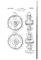
To accomplish the foregoing, as well as other objects of the invention, that will be apparent upon reading the following specification, the silencing means which embody my invention may be applied to a wheel as shown in the accompanying drawings, in which Figure 1 is a view, elevation, of a standard gear wheel provided with silencing rings,
Fig. 2 is a view, in longitudinal section, of the gear wheel, taken along the line II-II of Fig. 1,
Fig. 3 is a view, in elevation similar to Fig; 1, of a gear wheel provided with a modifled form of silencing rings, and
Fig. l is a view, in longitudinal section, of the gear wheel shown in Fig. 3, taken along the line IVIV.
A wheel, such as the standard gear wheel shown in the drawings, comprises in general, a central portion or hub 1 that is disposed to support a concentric rim 2 by means of an interconnecting structure, such as a web 3. In the particular structure illustrated, the Web 3 is formedintegrally with the hub 1 and the rim 2 and is provided with longitudinally disposed openings 4 in uniform spaced relation, from which excess metal has been removed for the purpose of reducing the weight of the Wheel. Ordinary gear wheels of this nature, which are applicable for use in locomotive and street-car-drive mechanisms, are formed from a single piece of steel by a forging operation.
In order that the gear wheel may be mounted upon a shaft 5, such as a railway vehicle axle, the hub 1 is provided with a centrally disposed bore or opening 6 of suitable diameter. For the purpose of rigidly securing the gear Wheel to the shaft 5, the inner diameter of the opening 6 is made slightly smaller than the outer diameter of the shaft 5 to constitute a press tit and the Wheel may be pressed upon the shaft in any Well known manner. As,
shown, the outer periphery 10 of the gear rim 8 is provided with gear teeth 11 of any suitable form for cooperating with mating teeth of a driving pinion (not shown).
In my co-pending application, Serial No. 306,816, filed Se tember 19, 1928, and assigned to the-lVesting ouse Electric and Manufacturing Company, it has beenexplained that gear wheels emit ringing sounds, particularly when operating at loads of such light nature that the cooperating gear teeth may be permitted to move relative to each other through the space provided by the normal backlash in the gearing. Under such conditions, the teeth of one gear-wheel may strike the teeth of the cooperating gear-wheel with considerable force. By reason of the hammer-likeblows which are applied to the teeth of the gearwheel by the cooperating teeth of a driving pinion, when operating under light-load c0nditions, the gear rim may be caused to vibrate -69 neredge of the rim 2and in the outer edge in substantially a radial direction at its natural frequency, which is usually within the audible range of sound frequency.
In accordance with the present invention, these objectionable vibrations may be suppressed, or damped, by applying non-sonorous material 12 to the rim, preferably on its inner surface. The material utilized for this purpose is of such nature that it will absorb and dissipate the'energy of vibration of the gear-rim 2 and thus prevent the energy from being radiated as sound. In practice, a fibrous non-metallic material, such as packing material which is known to the trade as Siegelite, has been found to be preferable,
although any other material which may be readily made to conform to the shape of the gear rim and which possesses aihigh degree of internal friction, may be utilized. It has been found that, in order to most effectively prevent the radiation of sound by a wheel, the damping material 12 should be applied to the inner surface of the gear rim 2 in a continuous strip, having the form of an annulus or ring, which is disposed concentric with the gear rim 2 and adjacent its edge or face. As shown in the drawings, it is preferable that two similar rings 12 of non-sonorous material be utilized, one adjacent to each face of the wheel.
, In order that the fibrous rings 12 may be held in close engagement with the inner surface of the rim 2, a pair of retainingrings 13 of wrought-iron or other suitable material are provided. As shown in Figs. 1 and 2, each of the retaining rings 13 may be in the form of a bar of suitable dimensions which has been rolled .into a ring having an outside diameter somewhat less than the diameter of the inner surface 14 of the rim 2.
In assembling the damping dev1ce, it is simply necessary toapply the strip 12 of nonsonorous material to the inner surface 14 of the rim 2, then place the -ring13 in its proper position within rim 2 andexpand it to force the material 12 into close contactwith the inner surface14 of the rim 2 by inserting a wedge or other suitable toolbetween the ends 15 which define the bar from which the ring was formed. A small amount of-metal 16 may be deposited between the ends 15. of the retaining ring 13 by means of a welding process-to tack or hold the ring in place. The wedging tool inaythen be withdrawn and the entire opening between the ends 15 be filled by means of deposited metal 16. In order to securely fasten the ring 13 in place, it is preferable that a plurality of corresponding notches'l'i and 18 be cut in the inof the ring 13, respectively, for instance, by. applying the corner of a grinding wheel, and that the recesses thus provided be filled-with dep t me a la Y Asshown in -F'gs. 3 and 4, in accordance with the modified form of the invention, the retaining ring 13 may be assembled from a plurality of segmental portions 21, 22, and 23. In assembling this structure, the segments are placed in their approximate positions and expanded into their operating po-- sitions by inserting wedges between their adjacent ends. After the wedges have been in-- serted, the segments 21, 22, and 23 may be securely fastened to the gear rim 2 by depositing metal l6 between the ends byawelding process and by welding each segment at its niid portion'to the rim 2 by filling the coop- .erating notches 17 and .18 with a welding deposit 19;
By either of these methods. of applying damping rings to the inner surface of aigear' rim, proper contact may be established be-- tween the non-sonorous material and the inner surface of the gearrim without the necessity of carefull -machining either the surface 11 or the perip cry of the retaining rings 13,'- inasmuch as the rings-13will deflect to con form to the circle definedby the surface-1 L and the fibrous damping material 12 when subjected to pressure. I I a From the foregoing description of my; sound-damping. means and the explanation of its construction, it will be apparentthat the invention-introduces a rugged, convenient and efiective means for preventingthe ringing of geanwheels. I
Althoughl have described-specific embodiments of my invention,those skilled in'the art will be enabled to provide silencing means of the invention,-as defined inthe appended claims. Y
I claim as my invention: .1 i 1. A gear wheel comprising, in combina tion, hub, web and rim portions, the rim portion extending laterally-relative to the web portion presenting an inner-face, non-sonorous material applied to the inner-face of the rimportion anda ring mounted inside the rim portion pressing the non-sonorous material against the inner-face of therimportion, said ring being independent of the gear members and cooperating only with the nonsonorous material for the purpose of deadening sound.
2. A gear wheel comprising. in; combination, a hub, web and rimportions, the rim portion extending laterally relative to the web portion presenting an inner-face, non sonorous material applied. to the outer. edge of the inner-face'ofgthe rim portionand a ring mounted inside the f rim portion pressing the non-sonorous. material against the outer edge of the inner-face of the rim-portion, said ringbeing independent'of'the gear members and *disposed to cooperate-with the non-sonorous material forg -the purposeoffabsorbing vibrations of the rim member to deaden sounds.
3. In a gear Wheel having an overhanging flange, in combination, a hub, means for securing the hub to the flange and sound-deadening means comprising a ring, of material other than that of which the flange is constituted, disposed to engage the inner surface of the flange and spaced from other portions of the gear Wheel.
4. A gear Wheel comprising a steel member constituting integrally formed hub, Web, and overhanging rim portions, a Wroughtiron ring disposed on the inner surface of said rim adjacent the outer edges thereof, and a ring of non-metallic material disposed between the wrought-iron ring and the rim portion for deadening the rim to prevent ringing While in operation.
In testimony whereof, I have hereunto subscribed my name this first day of Qctober,
RUDOLPH E. PETERSON.
Priority Applications (1)
| Application Number | Priority Date | Filing Date | Title |
|---|---|---|---|
| US398988A US1852538A (en) | 1929-10-11 | 1929-10-11 | Damping means for gear wheels |
Applications Claiming Priority (1)
| Application Number | Priority Date | Filing Date | Title |
|---|---|---|---|
| US398988A US1852538A (en) | 1929-10-11 | 1929-10-11 | Damping means for gear wheels |
Publications (1)
| Publication Number | Publication Date |
|---|---|
| US1852538A true US1852538A (en) | 1932-04-05 |
Family
ID=23577648
Family Applications (1)
| Application Number | Title | Priority Date | Filing Date |
|---|---|---|---|
| US398988A Expired - Lifetime US1852538A (en) | 1929-10-11 | 1929-10-11 | Damping means for gear wheels |
Country Status (1)
| Country | Link |
|---|---|
| US (1) | US1852538A (en) |
Cited By (13)
| Publication number | Priority date | Publication date | Assignee | Title |
|---|---|---|---|---|
| US2605132A (en) * | 1949-08-19 | 1952-07-29 | Budd Co | Sound-deadening and balancing means for railway wheels |
| WO1981000143A1 (en) * | 1979-07-06 | 1981-01-22 | Dana Corp | Gear wheel with vibration damping rings |
| EP0050567A1 (en) * | 1980-10-17 | 1982-04-28 | Compagnie Francaise Des Aciers Speciaux | Device for damping vibrations of a railway wheel |
| EP0134073A1 (en) * | 1983-08-19 | 1985-03-13 | Bridgestone Corporation | Gears with damped vibration |
| US4970909A (en) * | 1987-04-08 | 1990-11-20 | Helmut Pelzer | Sound attenuation in wheels |
| EP0559999A1 (en) * | 1991-11-07 | 1993-09-15 | Fip Industriale S.P.A. | Damping device for damping railroad and underground railroad train wheels and rail vehicle wheels in general |
| US5415063A (en) * | 1991-10-08 | 1995-05-16 | Firma Carl Freudenberg | Rotatable machine component with device for reducing acoustic vibrations |
| US20110250070A1 (en) * | 2008-12-10 | 2011-10-13 | Vestas Wind Systems A/S | Composite gear part for a gear arrangement and a method of forming a composite gear part |
| US20120220401A1 (en) * | 2010-08-06 | 2012-08-30 | Toyota Jidosha Kabushiki Kaisha | Cam sprocket and method for manufacturing the same |
| CN103912381A (en) * | 2013-01-09 | 2014-07-09 | 日立汽车系统株式会社 | Balancing device for internal combustion engines |
| EP2908029A3 (en) * | 2014-02-17 | 2016-05-25 | Hamilton Sundstrand Corporation | Electric generator oil pump driven gear |
| CN112020617A (en) * | 2018-04-27 | 2020-12-01 | 日立汽车系统株式会社 | Gear, balancing device, and balancing device with oil pump |
| US12044300B2 (en) | 2018-09-28 | 2024-07-23 | Isuzu Motors Limited | Corrected gear and method for correcting gear |
-
1929
- 1929-10-11 US US398988A patent/US1852538A/en not_active Expired - Lifetime
Cited By (20)
| Publication number | Priority date | Publication date | Assignee | Title |
|---|---|---|---|---|
| US2605132A (en) * | 1949-08-19 | 1952-07-29 | Budd Co | Sound-deadening and balancing means for railway wheels |
| WO1981000143A1 (en) * | 1979-07-06 | 1981-01-22 | Dana Corp | Gear wheel with vibration damping rings |
| US4317388A (en) * | 1979-07-06 | 1982-03-02 | Dana Corporation | Gear wheel with vibration damping rings |
| EP0050567A1 (en) * | 1980-10-17 | 1982-04-28 | Compagnie Francaise Des Aciers Speciaux | Device for damping vibrations of a railway wheel |
| EP0134073A1 (en) * | 1983-08-19 | 1985-03-13 | Bridgestone Corporation | Gears with damped vibration |
| US4970909A (en) * | 1987-04-08 | 1990-11-20 | Helmut Pelzer | Sound attenuation in wheels |
| US5415063A (en) * | 1991-10-08 | 1995-05-16 | Firma Carl Freudenberg | Rotatable machine component with device for reducing acoustic vibrations |
| EP0559999A1 (en) * | 1991-11-07 | 1993-09-15 | Fip Industriale S.P.A. | Damping device for damping railroad and underground railroad train wheels and rail vehicle wheels in general |
| US20110250070A1 (en) * | 2008-12-10 | 2011-10-13 | Vestas Wind Systems A/S | Composite gear part for a gear arrangement and a method of forming a composite gear part |
| US8978501B2 (en) * | 2008-12-10 | 2015-03-17 | Vestas Wind Systems A/S | Composite gear part for a gear arrangement and a method of forming a composite gear part |
| US8864612B2 (en) * | 2010-08-06 | 2014-10-21 | Toyota Jidosha Kabushiki Kaisha | Cam sprocket and method for manufacturing the same |
| US20120220401A1 (en) * | 2010-08-06 | 2012-08-30 | Toyota Jidosha Kabushiki Kaisha | Cam sprocket and method for manufacturing the same |
| CN103912381A (en) * | 2013-01-09 | 2014-07-09 | 日立汽车系统株式会社 | Balancing device for internal combustion engines |
| US20140190442A1 (en) * | 2013-01-09 | 2014-07-10 | Hitachi Automotive Systems, Ltd. | Balancer device of internal combustion engine |
| US9068626B2 (en) * | 2013-01-09 | 2015-06-30 | Hitachi Automotive Systems, Ltd. | Balancer device of internal combustion engine |
| CN103912381B (en) * | 2013-01-09 | 2017-10-27 | 日立汽车系统株式会社 | Balancing device for internal combustion engines |
| EP2908029A3 (en) * | 2014-02-17 | 2016-05-25 | Hamilton Sundstrand Corporation | Electric generator oil pump driven gear |
| US9494225B2 (en) | 2014-02-17 | 2016-11-15 | Hamilton Sundstrand Corporation | Electric generator oil pump driven gear |
| CN112020617A (en) * | 2018-04-27 | 2020-12-01 | 日立汽车系统株式会社 | Gear, balancing device, and balancing device with oil pump |
| US12044300B2 (en) | 2018-09-28 | 2024-07-23 | Isuzu Motors Limited | Corrected gear and method for correcting gear |
Similar Documents
| Publication | Publication Date | Title |
|---|---|---|
| US1852538A (en) | Damping means for gear wheels | |
| US2288438A (en) | Brake drum | |
| US1181175A (en) | Sprocket-wheel flange. | |
| US4353586A (en) | Vibration damped railway wheel | |
| US1852789A (en) | Damping means for gear wheels | |
| AU704275B2 (en) | Polyblock railway wheel | |
| GB2027844A (en) | Resonance absorber for rail wheel | |
| US2548839A (en) | Cushioned railway wheel | |
| CN109515060B (en) | Noise absorbing device for railway vehicle wheels and related railway vehicle wheels | |
| US1813820A (en) | Gear wheel and the like | |
| EP2046584B1 (en) | Device for reducing railway wheel noise when moving on rail | |
| CN105922817A (en) | Urban rail vehicle wheel composite damping vibration attenuation noise reduction device | |
| US2380776A (en) | Gear construction | |
| US10124625B2 (en) | Vehicle wheel for passenger cars | |
| JPS59501945A (en) | Elastic wheels for railway vehicles | |
| US2145343A (en) | Moving stair roller | |
| US2129178A (en) | Car wheel | |
| CZ2013798A3 (en) | Vibration and noise damper | |
| US1833413A (en) | Brake drum | |
| US1524555A (en) | Gear wheel | |
| US2293781A (en) | Friction clutch plate | |
| US1530072A (en) | Gear-wheel silencer | |
| US1602984A (en) | Wheel | |
| USRE16161E (en) | Composite gear wheel | |
| US1648413A (en) | Railway-car-wheel construction |