WO2020067006A1 - Dispositif d'évacuation de gaz de fuite - Google Patents
Dispositif d'évacuation de gaz de fuite Download PDFInfo
- Publication number
- WO2020067006A1 WO2020067006A1 PCT/JP2019/037261 JP2019037261W WO2020067006A1 WO 2020067006 A1 WO2020067006 A1 WO 2020067006A1 JP 2019037261 W JP2019037261 W JP 2019037261W WO 2020067006 A1 WO2020067006 A1 WO 2020067006A1
- Authority
- WO
- WIPO (PCT)
- Prior art keywords
- blow
- valve
- gas
- heating chamber
- drain
- Prior art date
Links
Images


Classifications
-
- F—MECHANICAL ENGINEERING; LIGHTING; HEATING; WEAPONS; BLASTING
- F02—COMBUSTION ENGINES; HOT-GAS OR COMBUSTION-PRODUCT ENGINE PLANTS
- F02F—CYLINDERS, PISTONS OR CASINGS, FOR COMBUSTION ENGINES; ARRANGEMENTS OF SEALINGS IN COMBUSTION ENGINES
- F02F7/00—Casings, e.g. crankcases or frames
- F02F7/0065—Shape of casings for other machine parts and purposes, e.g. utilisation purposes, safety
- F02F7/0073—Adaptations for fitting the engine, e.g. front-plates or bell-housings
-
- F—MECHANICAL ENGINEERING; LIGHTING; HEATING; WEAPONS; BLASTING
- F01—MACHINES OR ENGINES IN GENERAL; ENGINE PLANTS IN GENERAL; STEAM ENGINES
- F01M—LUBRICATING OF MACHINES OR ENGINES IN GENERAL; LUBRICATING INTERNAL COMBUSTION ENGINES; CRANKCASE VENTILATING
- F01M13/00—Crankcase ventilating or breathing
- F01M13/04—Crankcase ventilating or breathing having means for purifying air before leaving crankcase, e.g. removing oil
-
- F—MECHANICAL ENGINEERING; LIGHTING; HEATING; WEAPONS; BLASTING
- F01—MACHINES OR ENGINES IN GENERAL; ENGINE PLANTS IN GENERAL; STEAM ENGINES
- F01M—LUBRICATING OF MACHINES OR ENGINES IN GENERAL; LUBRICATING INTERNAL COMBUSTION ENGINES; CRANKCASE VENTILATING
- F01M11/00—Component parts, details or accessories, not provided for in, or of interest apart from, groups F01M1/00 - F01M9/00
- F01M11/04—Filling or draining lubricant of or from machines or engines
-
- F—MECHANICAL ENGINEERING; LIGHTING; HEATING; WEAPONS; BLASTING
- F01—MACHINES OR ENGINES IN GENERAL; ENGINE PLANTS IN GENERAL; STEAM ENGINES
- F01M—LUBRICATING OF MACHINES OR ENGINES IN GENERAL; LUBRICATING INTERNAL COMBUSTION ENGINES; CRANKCASE VENTILATING
- F01M13/00—Crankcase ventilating or breathing
- F01M13/04—Crankcase ventilating or breathing having means for purifying air before leaving crankcase, e.g. removing oil
- F01M13/0416—Crankcase ventilating or breathing having means for purifying air before leaving crankcase, e.g. removing oil arranged in valve-covers
-
- F—MECHANICAL ENGINEERING; LIGHTING; HEATING; WEAPONS; BLASTING
- F01—MACHINES OR ENGINES IN GENERAL; ENGINE PLANTS IN GENERAL; STEAM ENGINES
- F01M—LUBRICATING OF MACHINES OR ENGINES IN GENERAL; LUBRICATING INTERNAL COMBUSTION ENGINES; CRANKCASE VENTILATING
- F01M13/00—Crankcase ventilating or breathing
- F01M13/0011—Breather valves
- F01M2013/0027—Breather valves with a de-icing or defrosting system
-
- F—MECHANICAL ENGINEERING; LIGHTING; HEATING; WEAPONS; BLASTING
- F01—MACHINES OR ENGINES IN GENERAL; ENGINE PLANTS IN GENERAL; STEAM ENGINES
- F01M—LUBRICATING OF MACHINES OR ENGINES IN GENERAL; LUBRICATING INTERNAL COMBUSTION ENGINES; CRANKCASE VENTILATING
- F01M13/00—Crankcase ventilating or breathing
- F01M13/04—Crankcase ventilating or breathing having means for purifying air before leaving crankcase, e.g. removing oil
- F01M2013/0422—Separating oil and gas with a centrifuge device
-
- F—MECHANICAL ENGINEERING; LIGHTING; HEATING; WEAPONS; BLASTING
- F01—MACHINES OR ENGINES IN GENERAL; ENGINE PLANTS IN GENERAL; STEAM ENGINES
- F01M—LUBRICATING OF MACHINES OR ENGINES IN GENERAL; LUBRICATING INTERNAL COMBUSTION ENGINES; CRANKCASE VENTILATING
- F01M13/00—Crankcase ventilating or breathing
- F01M13/04—Crankcase ventilating or breathing having means for purifying air before leaving crankcase, e.g. removing oil
- F01M2013/0466—Crankcase ventilating or breathing having means for purifying air before leaving crankcase, e.g. removing oil with electrostatic means
-
- F—MECHANICAL ENGINEERING; LIGHTING; HEATING; WEAPONS; BLASTING
- F01—MACHINES OR ENGINES IN GENERAL; ENGINE PLANTS IN GENERAL; STEAM ENGINES
- F01M—LUBRICATING OF MACHINES OR ENGINES IN GENERAL; LUBRICATING INTERNAL COMBUSTION ENGINES; CRANKCASE VENTILATING
- F01M13/00—Crankcase ventilating or breathing
- F01M13/04—Crankcase ventilating or breathing having means for purifying air before leaving crankcase, e.g. removing oil
- F01M2013/0472—Crankcase ventilating or breathing having means for purifying air before leaving crankcase, e.g. removing oil using heating means
Definitions
- the present disclosure relates to a blow-by gas discharge device, and more particularly, to a device that discharges blow-by gas to the atmosphere through a blow-by gas pipe exposed to outside air.
- the blow-by gas generated in the crank chamber of the internal combustion engine is usually returned to the intake system and sent to the combustion chamber, where it is burned together with the air-fuel mixture in the combustion chamber.
- the present disclosure provides a blow-by gas discharge device that can suppress freezing of condensed water in a blow-by gas pipe.
- the blow-by gas exhaust device includes: A blow-by gas pipe that extends from the height position of the upper end portion of the internal combustion engine to the height position of the lower end portion, is exposed to the outside air, and has an outlet that is open to the atmosphere, A heating chamber that is provided in the middle of the blow-by gas pipe and is formed in a flywheel housing of the internal combustion engine, and heats a blow-by gas, A drain mechanism provided in the heating chamber, for discharging oil deposited in the heating chamber, Is provided.
- the drain mechanism may include a drain valve that prohibits oil discharge when the valve is closed and allows oil discharge when the valve is opened.
- the drain valve may be formed by a check valve, and the check valve may have a valve element and an urging member for urging the valve element to the valve closing side.
- the drain valve may be formed by a drain bolt.
- the drain valve may be configured to be accessible through a hole provided in the flywheel housing.
- freezing of condensed water in the blow-by gas pipe can be suppressed.
- FIG. 1 is a vertical sectional side view showing the structure of the end portion of the internal combustion engine.
- FIG. 2 is a schematic longitudinal rear view showing the heating chamber.
- FIG. 3 is a schematic longitudinal rear view showing the drain mechanism.
- FIG. 4 is a schematic longitudinal rear view for explaining a working method at the time of oil discharge.
- FIG. 5 is a schematic longitudinal rear view showing a drain mechanism according to a first modification.
- FIG. 6 is a schematic longitudinal rear view showing a drain mechanism according to a second modification.
- 7A and 7B show a drain mechanism according to a third modified example.
- FIG. 7A is a left side view of a drain bolt
- FIG. 7B is a schematic vertical sectional rear view.
- 8A and 8B show a drain mechanism of a fourth modified example, where FIG. 8A is a left side view of a drain bolt, and FIG. 8B is a schematic longitudinal rear view.
- FIG. 9 is a schematic longitudinal rear view showing a drain mechanism according to a
- FIG. 1 is a side sectional view showing the structure of the end of the internal combustion engine according to this embodiment.
- the internal combustion engine (engine) 1 is a diesel engine mounted on a vehicle (not shown), and the vehicle is a large vehicle such as a truck.
- the type and use of the vehicle and the engine are not particularly limited.
- the vehicle may be a small vehicle such as a passenger car, or the engine may be a gasoline engine.
- the engine is installed vertically in the vehicle. The front, rear, left, right, up, and down directions of the vehicle and the engine are as illustrated.
- the engine 1 includes a cylinder block 2 integrally having a crankcase (not shown), a cylinder head 3 fastened to an upper end of the cylinder block 2, a head cover 4 fastened to an upper end of the cylinder head 3, a crank, And an oil pan 5 fastened to the lower end of the case.
- a crankshaft 6 is rotatably supported by the crankcase, and a camshaft 7 is rotatably supported by the cylinder head 3.
- a flywheel 8 is attached to a rear end surface of the crankshaft 6 by a plurality of bolts 9.
- a flywheel housing 10 that accommodates the flywheel 8 is attached to the cylinder block 2 with bolts or the like (not shown).
- the flywheel housing 10 may be formed integrally with the cylinder block 2. Inside the flywheel housing 10, there is formed a cylindrical flywheel chamber 11 for accommodating the flywheel 8 substantially rotatably.
- a clutch device (not shown) is connected to the rear end of the flywheel housing 10, and a clutch input shaft of the clutch device is coaxially connected to the crankshaft 6.
- a part of the oil pan 5 is attached to the flywheel housing 10 with bolts 12.
- a mechanism chamber is formed between the rear end face of the cylinder block 2 and the flywheel housing 10, and a power transmission mechanism for transmitting power from the crankshaft 6 to the camshaft 7 is housed in the mechanism chamber.
- the power transmission mechanism is formed by a gear mechanism 13 configured by meshing a plurality of gears
- the mechanism chamber is formed by a gear chamber 14.
- the type of the power transmission mechanism is arbitrary, and may be formed by, for example, a chain mechanism.
- the gear mechanism 13 includes a crank gear 15 fixed to the crankshaft 6, a cam gear 16 fixed to the camshaft 7, and a plurality (two in the present embodiment) interposed between the crank gear 15 and the cam gear 16. Intermediate gears 17A, 17B.
- the gear chamber 14 is communicated with a crank chamber 18 in the crank case, a valve operating chamber 3A on the cylinder head 3, and a cover chamber 19 in the head cover 4.
- C1 indicates the central axis of the crankshaft 6, and C2 indicates the central axis of the camshaft 7, respectively.
- a gear chamber partition wall 20 having a half-width frame shape (U-shape) in a plan view is integrally formed, and a space inside the gear chamber partition wall 20 is one of the gear chambers 14. Department.
- the upper end surface of the flywheel housing 10 is in close contact with the lower end surface of the gear chamber partition wall 20, and the lower end surface of the head cover 4 is in close contact with the upper end surface of the gear chamber partition wall 20.
- the rear end of the crankshaft 6 protrudes into the rear flywheel chamber 11 through an insertion hole 21 provided in the flywheel housing 10.
- a seal member (not shown) for preventing oil or gas from leaking from the gear chamber 14 is provided around the insertion hole 21.
- blow-by gas leaks from the combustion chamber in the cylinder into the crank chamber 18 through the gap between the piston ring and the cylinder bore.
- the blow-by gas is introduced into the cover chamber 19 through the gear chamber 14 and other gas passage holes.
- an oil separator 22 for separating oil from blow-by gas is formed in the cover chamber 19.
- a meandering passage for flowing blow-by gas is formed in the oil separator 22.
- the blow-by gas after the oil is separated by the oil separator 22 is discharged to the atmosphere through a gas pipe 23 serving as a blow-by gas pipe.
- the gas pipe 23 is exposed to the outside air and is directly cooled by the outside air.
- the gas pipe 23 of the present embodiment is formed of a metal such as stainless steel, and is entirely exposed to the outside air, and is easily cooled by the outside air.
- the blow-by gas passing through the gas pipe 23 is also cooled, and condensed water due to the blow-by gas is generated in the gas pipe 23. If the outside air temperature is below the freezing point in a cold area, for example, the condensed water may freeze and block the gas pipe 23. If the inside of the gas pipe 23 is closed, there is a possibility that discharge of blow-by gas may be hindered.
- a heating chamber 24 for heating the blow-by gas is provided in the middle of the gas pipe 23, and the blow-by gas is heated in the heating chamber 24, thereby generating condensed water caused by the blow-by gas, The freezing is suppressed.
- the heating chamber 24 is formed in the flywheel housing 10 and is adjacent to the gear chamber 14 with a partition wall (a lid 41 described later in the present embodiment) interposed therebetween, and mainly receives heat received from oil in the gear chamber 14.
- the blow-by gas is heated.
- the blow-by gas can be efficiently heated without providing a dedicated heat source.
- the gas pipe 23 extends from the upper end of the engine 1 to the lower end of the engine 1 as a whole. However, the gas pipe 23 is divided into two parts at an intermediate position in the height direction, and is divided into an upstream gas pipe 25 and a downstream gas pipe 26 (shown by phantom lines in FIG. 1).
- the heating chamber 24 is connected between the upstream gas pipe 25 and the downstream gas pipe 26.
- Each of the upstream gas pipe 25 and the downstream gas pipe 26 is formed of a metal such as stainless steel, and is exposed to the outside air outside the engine.
- the inlet 27 of the upstream gas pipe 25 is connected to the oil separator 22.
- the head cover 4 is provided with an outlet 28 for extracting the blow-by gas after oil separation from the oil separator 22, and the inlet 27 of the upstream gas pipe 25 is connected to the outlet 28.
- the inlet 27 of the upstream gas pipe 25 forms an inlet of the gas pipe 23. Since the head cover 4 and the oil separator 22 are provided at the height of the upper end of the engine 1 and the inlet 27 of the upstream gas pipe 25 is connected to the oil separator 22, the gas pipe 23 It will extend downstream from the height position of the upper end.
- the oil separator 22 may be provided outside the head cover 4 instead of inside.
- Reference numeral 22 ⁇ / b> A in the figure indicates a partition wall that partitions the oil separator 22.
- the outlet 29 of the upstream gas pipe 25 is connected to the heating chamber 24.
- An inlet 30 for introducing blow-by gas into the heating chamber 24 is provided at an upper end and a right end of the heating chamber 24, and an outlet 29 of the upstream gas pipe 25 is connected to the inlet 30. .
- the inlet 31 of the downstream gas pipe 26 is also connected to the heating chamber 24.
- An outlet 32 for discharging blow-by gas from the heating chamber 24 is provided at the upper end and the left end of the heating chamber 24, and the inlet 31 of the downstream gas pipe 26 is connected to the outlet 32. .
- the downstream gas pipe 26 passes through the left side of the flywheel housing 10 and extends downward toward the downstream side.
- the outlet 33 of the downstream gas pipe 26 is disposed at the height of the lower end of the engine 1 and is open to the atmosphere in a downward direction.
- the outlet 33 of the downstream gas pipe 26 forms an outlet of the gas pipe 23.
- the gas pipe 23 extends to the level of the lower end of the engine 1.
- the heating chamber 24 is formed inside the flywheel housing 10 and at the upper end.
- the heating chamber 24 is mainly defined by a cavity 40 formed in the flywheel housing 10 and opening forward, and a lid 41 closing a front end opening of the cavity 40.
- the flywheel housing 10 is cast from aluminum or iron
- the lid 41 is formed from any metal plate.
- the material of the lid 41 is excellent in heat resistance and corrosion resistance and has relatively high thermal conductivity, for example, aluminum or stainless steel.
- the lid 41 is overlaid on the lid mounting surface 42 of the flywheel housing 10 located around the front end opening of the cavity 40, and is detachably and air-tightly fixed by a plurality of bolts 43.
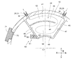
- the heating chamber 24 of the present embodiment has a fan shape or a substantially fan shape extending around the crankshaft center axis C1 when viewed from the rear (that is, one end side in the direction of the crankshaft center axis C1). Have been. The same applies to the rear view shape of the lid 41.
- An inlet 30 is provided on the right side of the upper end of the heating chamber 24, and a discharge port 32 is provided on the left side of the upper end.
- the central axes of the inlet 30 and the outlet 32 are substantially along the radial direction with respect to the crankshaft central axis C1.
- a partition wall 44 that forms a meandering passage in the heating chamber 24 is provided inside the heating chamber 24.
- the partition wall 44 is formed integrally with the flywheel housing 10. As shown in FIG. 1, the partition wall 44 integrally and linearly protrudes forward from the rear inner wall surface 45 of the heating chamber 24, which is the bottom surface of the cavity 40, and comes into contact with the lid 41 in a gas-tight manner. The space in the room 24 is vertically divided. As shown in FIG. 2, the partition wall 44 extends integrally and in an arc shape from the left inner wall surface 46 of the heating chamber 24, which is one side surface of the cavity 40, to the right side. It terminates at a position where a predetermined gap 48 is formed between itself and the right inner wall surface 47 of the chamber 24.
- the outlet of the inlet 30 is directed toward the gap 48 and, consequently, the lower inner wall surface 49 of the heating chamber 24.
- the inlet 30 can send the blow-by gas discharged from the inlet 30 straight through the gap 48 to the space 50 below the partition wall 44, as indicated by the arrow.
- the heating chamber 24 and the flywheel chamber 11 overlap in the vertical direction, and the lower end of the heating chamber 24 is disposed in front of the upper end of the flywheel chamber 11.
- a step 51 projecting forward is provided on a rear inner wall surface 45 of the heating chamber 24.
- the shape of the heating chamber 24 is not limited to the above-mentioned shape, and can be changed to any shape.
- a plurality of partition walls 44 may be provided instead of one as in the present embodiment. If possible, the step 51 may not be provided.
- the blow-by gas after the oil is separated by the oil separator 22 is sent to the heating chamber 24. Therefore, the oil content of the blow-by gas in the heating chamber 24 is relatively small. However, even after a long period of time, an unacceptable amount of oil may accumulate in the heating chamber 24.
- a drain mechanism 60 for discharging oil accumulated in the heating chamber 24 is provided in the heating chamber 24. Accordingly, the oil accumulated in the heating chamber 24 can be discharged, and a problem caused by the accumulated oil (for example, obstructing a desired flow of blow-by gas in the heating chamber 24) can be solved.
- the drain mechanism 60 is provided at the lowest position of the heating chamber 24, specifically, at the lower left corner, so that the oil accumulated in the heating chamber 24 can be discharged as much as possible. Has become.
- the drain mechanism 60 includes a drain valve that can be opened and closed. The drain valve prohibits oil discharge when the valve is closed and allows oil discharge when the valve is opened.
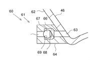
- the drain valve is formed by the check valve 61.
- a horizontal drain hole 63 that penetrates the left wall 62 is provided at the lowest position of the left wall 62 that forms the left inner wall 46 of the heating chamber 24.
- a check valve 61 is attached to the outer surface of the left side wall portion 62 by appropriate means such as welding or bolting so as to communicate with the drain hole 63.
- the check valve 61 includes a valve body 64 attached to the left side wall portion 62, a valve hole 65 formed through the valve body 64, and a valve body chamber 66 formed with an enlarged diameter in the middle of the valve hole 65.
- the valve includes a valve body 67 disposed in the valve body chamber 66 and a spring 68 as an urging member for urging the valve body 67 toward the valve closing side.
- the valve hole 65 communicates coaxially with the drain hole 63 and extends horizontally and horizontally.
- the valve body 67 is formed of a metal ball such as an iron ball.
- the spring 68 urges the valve body 67 to the left side on the side opposite to the heating chamber 24 to press the valve body 67 against the valve seat 69 to close the check valve 61. Accordingly, in the illustrated example, the left side, which is the side opposite to the heating chamber 24, is the valve closing side, and the right side, which is the heating chamber 24 side, is the valve opening side.
- the spring 68 is formed by a coil spring.
- the check valve 61 is accessible through a hole provided in the flywheel housing 10, that is, a housing hole 70.
- the housing hole 70 is a service hole for visually confirming the inside of the flywheel housing 10 after assembling, and is normally closed by a detachable plug 71 such as a screw-in type. By removing the plug 71, the check valve 61 becomes accessible from outside the flywheel housing 10.
- the valve hole 65 is directed to a housing hole 70 on the left side thereof.
- the flow of the blow-by gas in the configuration of the present embodiment is as shown by arrows in FIGS. 1 and 2.
- the blow-by gas from which oil has been separated by the oil separator 22 flows into the heating chamber 24 through the upstream gas pipe 25 and the inlet 30.
- the blow-by gas discharged from the inlet 30 linearly and smoothly enters the lower space 50 through the gap 48.
- the blow-by gas once proceeds to the left in the lower space 50, makes a U-turn to the right, rises in the gap 48, and enters the upper space 52 partitioned by the partition wall 44.
- the gas is discharged from the outlet 32 into the downstream gas pipe 26.
- the blow-by gas flows through the downstream gas pipe 26 and is discharged to the outside air (that is, released to the atmosphere) through the outlet 33.
- the blow-by gas can meander in the heating chamber 24 to temporarily stay therein.
- relatively high temperature oil in the gear chamber 14 for lubricating the gear mechanism 13 is attached to the flywheel housing 10 and the lid 41, and the flywheel housing 10 and the lid 41 are heated by the oil. Therefore, the heat can heat the blow-by gas in the heating chamber 24 to keep the temperature or at least suppress the temperature drop. Therefore, it is possible to suppress the generation of condensed water due to the condensation of the moisture contained in the blow-by gas, the freezing of the condensed water in the gas pipe 23, and the blocking of the gas pipe 23 due to the freezing. Since the blow-by gas meanders and stays in the heating chamber 24, the heating time can be increased, which is advantageous for suppressing the generation of condensed water and the like.
- the blow-by gas is cooled by the outside air and tends to decrease its temperature toward the downstream side in the gas pipe 23 exposed to the outside air.
- the most severe is the outlet 33 of the downstream gas pipe 26, where the temperature of the blow-by gas is the lowest.
- the outside air including the traveling wind enters the exit portion 33, and the outside air entering the exit portion 33 has a very low temperature in a cold region or the like. Under these circumstances, condensed water and freezing are likely to occur inside the outlet portion 33.
- the blow-by gas can be heated in the heating chamber 24 in the middle of the gas pipe 23 because the temperature of the blow-by gas when reaching the outlet 33 is increased, and the temperature of the outlet 33 is increased. It is possible to effectively suppress the generation and freezing of condensed water inside.
- the heating chamber 24 is formed by the cavity 40 integrally formed with the flywheel housing 10 and the lid 41 for closing the same, the complete closed space is formed inside the flywheel housing.
- the formation of the heating chamber can be facilitated as compared with the case where a certain heating chamber is formed.
- the lid 41 is detachable, the inside of the heating chamber 24 can be inspected and maintained by removing the lid 41 if necessary.
- the lid 41 can be regarded as a part of the divided flywheel housing 10.
- a heating chamber which is a completely closed space may be formed inside the flywheel housing.
- the maintenance person when discharging the oil O accumulated in the heating chamber 24, the maintenance person removes the plug 71 and inserts a jig or a tool 72 into the flywheel housing 10 through the housing hole 70. Then, the tip of the tool 72 is inserted into the valve hole 65, the tool 72 is pushed toward the valve opening side (right side), and the valve body 67 is pushed out at the tip of the tool 72 against the urging force of the spring 68 toward the valve opening side. Is opened.
- the oil O is discharged from the heating chamber 24 through the drain hole 63 and the valve hole 65 in this order.
- the discharged oil O is dropped into the flywheel housing 10, but there is no problem because the inside of the flywheel housing 10 is also in an oil atmosphere and the amount of oil is very small.
- the oil can be periodically discharged at a time when the maintenance is performed, and the oil accumulation can be suppressed. Can be solved. Further, since the oil can be discharged only by inserting the tool 72 through the housing hole 70 and pushing the valve body 67 at the tip of the tool 72, the oil discharging operation can be performed very easily.
- valve body 67 of the check valve 61 is formed by a hollow piston having a bottomed cylindrical shape.
- One end on the left side of the valve body 67 is closed and pressed against a valve seat 69 by a spring 68.
- the other end on the right side of the valve body 67 is opened, from which a spring 68 is inserted into the valve body 67.
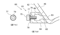
- the drain valve is formed by the drain bolt 75.
- the drain bolt 75 is fastened to a female screw 76 provided on the inner surface of the outlet of the valve hole 65 to close the valve hole 65. As a result, the drain valve is closed.
- the drain bolt 75 is formed by a general hexagonal bolt having a hexagonal head 77 and is fastened to the female screw 76 with a washer 78 interposed therebetween.
- the drain bolt 75 is loosened, the oil leaks out from the gap between the drain bolt 75 and the female screw 76 and is discharged, so that the valve hole 65 is substantially opened and the drain valve is opened.
- the drain bolt 75 is brought into the valve closed state and the valve open state by tightening and loosening, and can be regarded as a drain valve.
- a socket wrench (not shown) is inserted into the flywheel housing 10 through the housing hole 70, and the socket of the socket wrench is fitted to the head 77. Then, by turning the socket wrench to loosen the drain bolt 75, the drain valve is opened and the oil is discharged.
- the drain bolt 75 is formed by a general hexagonal bolt having a hexagonal hole 79.
- a hexagon wrench is inserted through the housing hole 70, and the drain bolt 75 is loosened by the hexagon wrench.
- the drain bolt 75 is formed by a hexagon socket head bolt.
- a groove 81 extending in the axial direction is formed in the male screw portion 80 of the drain bolt 75.
- the female screw 76 is loosened by loosening the drain bolt 75 so that the groove 81 extends from a position on the heating chamber 24 side of the female screw 76 to a position on the opposite side of the heating chamber 24 from the female screw 76.
- the shortcut is to drain the oil quickly.
- the groove 81 can be applied to any drain bolt including the drain bolt 75 of the second modification (FIG. 6).
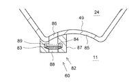
- the drain mechanism 60 is formed by a check valve 82, but this check valve 82 is not a spring type as in the basic embodiment (FIG. 3) but a gravity type.
- valve element 83 of the check valve 82 is seated on the valve seat 84 by its own weight when the engine is stopped, and closes the check valve 82.
- the valve element 83 rises as indicated by the phantom line due to the pressure in the flywheel chamber 11 that has risen due to the rotation of the flywheel 8, separates from the valve seat 84, and opens the check valve 82. .
- oil can be discharged during engine operation.
- a vertical drain hole 86 penetrating the lower wall portion 85 is provided at the lowest position of the lower wall portion 85 forming the lower inner wall surface 49 of the heating chamber 24.
- a check valve 82 is attached to the outer surface of the lower side wall 85 by appropriate means such as welding or bolting so as to communicate with the drain hole 86.
- the check valve 82 includes a valve body 87 attached to the lower side wall portion 85, a valve hole 88 formed through the valve body 87, and a valve body chamber 89 formed with an enlarged diameter in the middle of the valve hole 88. And a valve element 83 disposed in the valve element chamber 89 so as to be able to move up and down.
- the valve hole 88 extends coaxially with the drain hole 86 in the vertical direction.
- the valve element 83 is formed in a disk shape.
- the valve seat 84 and the lower peripheral edge of the valve body 83 seated thereon are formed in a tapered shape.
- the oil separator 22 may be omitted. In this case, the oil stays in the heating chamber 24 at a higher speed, but the staying oil can be discharged by the drain mechanism.
- the installation position of the drain mechanism can be changed to a position other than the above.
- freezing of condensed water in the blow-by gas pipe can be suppressed.
Abstract
L'invention concerne un dispositif d'évacuation de gaz de fuite pourvu : d'un tuyau de gaz de fuite (23) qui s'étend de la position de hauteur d'extrémité supérieure à la position de hauteur d'extrémité inférieure d'un moteur à combustion interne (1) et qui a une sortie (33) exposée à l'air extérieur et ouverte à l'atmosphère ; d'une chambre de chauffage (24) qui est disposée à mi-chemin du tuyau de gaz de fuite, et formée dans un carter de volant (10) du moteur à combustion interne de façon à chauffer un gaz de fuite ; et d'un mécanisme de drain qui est disposé dans la chambre de chauffage de façon à évacuer une huile accumulée dans la chambre de chauffage.
Priority Applications (3)
| Application Number | Priority Date | Filing Date | Title |
|---|---|---|---|
| DE112019004876.7T DE112019004876T5 (de) | 2018-09-27 | 2019-09-24 | Abführvorrichtung für blowby-gas |
| US17/280,569 US11396834B2 (en) | 2018-09-27 | 2019-09-24 | Blow-by gas discharging device |
| CN201980064035.2A CN112771254B (zh) | 2018-09-27 | 2019-09-24 | 窜缸混合气排出装置 |
Applications Claiming Priority (2)
| Application Number | Priority Date | Filing Date | Title |
|---|---|---|---|
| JP2018-182123 | 2018-09-27 | ||
| JP2018182123A JP2020051353A (ja) | 2018-09-27 | 2018-09-27 | ブローバイガス排出装置 |
Publications (1)
| Publication Number | Publication Date |
|---|---|
| WO2020067006A1 true WO2020067006A1 (fr) | 2020-04-02 |
Family
ID=69951355
Family Applications (1)
| Application Number | Title | Priority Date | Filing Date |
|---|---|---|---|
| PCT/JP2019/037261 WO2020067006A1 (fr) | 2018-09-27 | 2019-09-24 | Dispositif d'évacuation de gaz de fuite |
Country Status (5)
| Country | Link |
|---|---|
| US (1) | US11396834B2 (fr) |
| JP (1) | JP2020051353A (fr) |
| CN (1) | CN112771254B (fr) |
| DE (1) | DE112019004876T5 (fr) |
| WO (1) | WO2020067006A1 (fr) |
Cited By (1)
| Publication number | Priority date | Publication date | Assignee | Title |
|---|---|---|---|---|
| EP4023861A1 (fr) * | 2020-12-31 | 2022-07-06 | Sogefi Air & Cooling USA, Inc. | Soupape de vidange de séparateur air-huile et procédé d'utilisation associé |
Families Citing this family (1)
| Publication number | Priority date | Publication date | Assignee | Title |
|---|---|---|---|---|
| US11598235B2 (en) * | 2021-03-16 | 2023-03-07 | Deere & Company | Internal combustion engine with internal oil heating of blowby gas |
Citations (6)
| Publication number | Priority date | Publication date | Assignee | Title |
|---|---|---|---|---|
| JPS58156112U (ja) * | 1982-04-15 | 1983-10-18 | 株式会社クボタ | 耐転倒内燃機関のブレザ−装置 |
| JPS62721U (fr) * | 1985-06-19 | 1987-01-06 | ||
| JPH0195513U (fr) * | 1987-12-18 | 1989-06-23 | ||
| US20110061635A1 (en) * | 2009-09-15 | 2011-03-17 | Peter Bukhenik | Crankcase Ventilation Device for Internal Combustion Engines |
| JP2012172628A (ja) * | 2011-02-23 | 2012-09-10 | Honda Motor Co Ltd | 内燃機関の燃料ガス処理装置 |
| WO2013094452A1 (fr) * | 2011-12-20 | 2013-06-27 | 株式会社マーレ フィルターシステムズ | Structure de vidange d'huile destinée à un séparateur de brouillard d'huile |
Family Cites Families (1)
| Publication number | Priority date | Publication date | Assignee | Title |
|---|---|---|---|---|
| JP2016183604A (ja) * | 2015-03-26 | 2016-10-20 | いすゞ自動車株式会社 | ブローバイガス排出構造 |
-
2018
- 2018-09-27 JP JP2018182123A patent/JP2020051353A/ja active Pending
-
2019
- 2019-09-24 CN CN201980064035.2A patent/CN112771254B/zh active Active
- 2019-09-24 US US17/280,569 patent/US11396834B2/en active Active
- 2019-09-24 DE DE112019004876.7T patent/DE112019004876T5/de active Pending
- 2019-09-24 WO PCT/JP2019/037261 patent/WO2020067006A1/fr active Application Filing
Patent Citations (6)
| Publication number | Priority date | Publication date | Assignee | Title |
|---|---|---|---|---|
| JPS58156112U (ja) * | 1982-04-15 | 1983-10-18 | 株式会社クボタ | 耐転倒内燃機関のブレザ−装置 |
| JPS62721U (fr) * | 1985-06-19 | 1987-01-06 | ||
| JPH0195513U (fr) * | 1987-12-18 | 1989-06-23 | ||
| US20110061635A1 (en) * | 2009-09-15 | 2011-03-17 | Peter Bukhenik | Crankcase Ventilation Device for Internal Combustion Engines |
| JP2012172628A (ja) * | 2011-02-23 | 2012-09-10 | Honda Motor Co Ltd | 内燃機関の燃料ガス処理装置 |
| WO2013094452A1 (fr) * | 2011-12-20 | 2013-06-27 | 株式会社マーレ フィルターシステムズ | Structure de vidange d'huile destinée à un séparateur de brouillard d'huile |
Cited By (1)
| Publication number | Priority date | Publication date | Assignee | Title |
|---|---|---|---|---|
| EP4023861A1 (fr) * | 2020-12-31 | 2022-07-06 | Sogefi Air & Cooling USA, Inc. | Soupape de vidange de séparateur air-huile et procédé d'utilisation associé |
Also Published As
| Publication number | Publication date |
|---|---|
| US11396834B2 (en) | 2022-07-26 |
| CN112771254A (zh) | 2021-05-07 |
| US20220003138A1 (en) | 2022-01-06 |
| DE112019004876T5 (de) | 2021-06-17 |
| JP2020051353A (ja) | 2020-04-02 |
| CN112771254B (zh) | 2023-06-27 |
Similar Documents
| Publication | Publication Date | Title |
|---|---|---|
| EP2630346B1 (fr) | Structure d'installation de soupape pcv | |
| US20090126659A1 (en) | Turbocharged engine cylinder head internal cooling | |
| KR100570236B1 (ko) | 내연 기관용 블로바이 가스 순환 장치 | |
| WO2020067006A1 (fr) | Dispositif d'évacuation de gaz de fuite | |
| JP2008025347A (ja) | ブローバイガス還元装置のオイル回収構造 | |
| US20090199794A1 (en) | Crankcase ventilation system | |
| JP5983350B2 (ja) | Pcvバルブの取付け構造 | |
| JP2006022700A (ja) | ブローバイガス還元装置 | |
| US20130269636A1 (en) | Engine assembly with engine block-mounted air-oil separator and method of ventilating an engine crankcase | |
| JP2006299932A (ja) | ブローバイガス還元装置の熱交換構造 | |
| WO2020066992A1 (fr) | Dispositif d'évacuation de gaz de carter | |
| JP6782200B2 (ja) | ブローバイガス還流装置 | |
| WO2020067080A1 (fr) | Dispositif d'évacuation de gaz de soufflage | |
| JP5550813B2 (ja) | 内燃機関における排気ガス還流装置 | |
| CA2889277C (fr) | Configuration de tube de tige-poussoir de tete de cylindre de moteur | |
| JP2005140104A (ja) | クランクケース | |
| KR100680360B1 (ko) | 실린더헤드커버구조 | |
| JP2020051354A (ja) | ブローバイガス排出装置 | |
| JP7103928B2 (ja) | ブローバイガス還流装置 | |
| CN215979544U (zh) | 油底壳、发动机和车辆 | |
| JP6582707B2 (ja) | エンジンのオイル昇温構造 | |
| CN109057909A (zh) | 一种多功能机油盘总成 | |
| JP2013234641A (ja) | 内燃機関の吸気装置 | |
| JP2019044634A (ja) | 内燃機関 | |
| KR101956391B1 (ko) | 크랭크 케이스의 결빙 방지 장치 |
Legal Events
| Date | Code | Title | Description |
|---|---|---|---|
| 121 | Ep: the epo has been informed by wipo that ep was designated in this application |
Ref document number: 19867473 Country of ref document: EP Kind code of ref document: A1 |
|
| WWE | Wipo information: entry into national phase |
Ref document number: 2101001778 Country of ref document: TH |
|
| 122 | Ep: pct application non-entry in european phase |
Ref document number: 19867473 Country of ref document: EP Kind code of ref document: A1 |