WO2020067006A1 - Blow-by gas discharging device - Google Patents
Blow-by gas discharging device Download PDFInfo
- Publication number
- WO2020067006A1 WO2020067006A1 PCT/JP2019/037261 JP2019037261W WO2020067006A1 WO 2020067006 A1 WO2020067006 A1 WO 2020067006A1 JP 2019037261 W JP2019037261 W JP 2019037261W WO 2020067006 A1 WO2020067006 A1 WO 2020067006A1
- Authority
- WO
- WIPO (PCT)
- Prior art keywords
- blow
- valve
- gas
- heating chamber
- drain
- Prior art date
Links
Images


Classifications
-
- F—MECHANICAL ENGINEERING; LIGHTING; HEATING; WEAPONS; BLASTING
- F02—COMBUSTION ENGINES; HOT-GAS OR COMBUSTION-PRODUCT ENGINE PLANTS
- F02F—CYLINDERS, PISTONS OR CASINGS, FOR COMBUSTION ENGINES; ARRANGEMENTS OF SEALINGS IN COMBUSTION ENGINES
- F02F7/00—Casings, e.g. crankcases or frames
- F02F7/0065—Shape of casings for other machine parts and purposes, e.g. utilisation purposes, safety
- F02F7/0073—Adaptations for fitting the engine, e.g. front-plates or bell-housings
-
- F—MECHANICAL ENGINEERING; LIGHTING; HEATING; WEAPONS; BLASTING
- F01—MACHINES OR ENGINES IN GENERAL; ENGINE PLANTS IN GENERAL; STEAM ENGINES
- F01M—LUBRICATING OF MACHINES OR ENGINES IN GENERAL; LUBRICATING INTERNAL COMBUSTION ENGINES; CRANKCASE VENTILATING
- F01M13/00—Crankcase ventilating or breathing
- F01M13/04—Crankcase ventilating or breathing having means for purifying air before leaving crankcase, e.g. removing oil
-
- F—MECHANICAL ENGINEERING; LIGHTING; HEATING; WEAPONS; BLASTING
- F01—MACHINES OR ENGINES IN GENERAL; ENGINE PLANTS IN GENERAL; STEAM ENGINES
- F01M—LUBRICATING OF MACHINES OR ENGINES IN GENERAL; LUBRICATING INTERNAL COMBUSTION ENGINES; CRANKCASE VENTILATING
- F01M11/00—Component parts, details or accessories, not provided for in, or of interest apart from, groups F01M1/00 - F01M9/00
- F01M11/04—Filling or draining lubricant of or from machines or engines
-
- F—MECHANICAL ENGINEERING; LIGHTING; HEATING; WEAPONS; BLASTING
- F01—MACHINES OR ENGINES IN GENERAL; ENGINE PLANTS IN GENERAL; STEAM ENGINES
- F01M—LUBRICATING OF MACHINES OR ENGINES IN GENERAL; LUBRICATING INTERNAL COMBUSTION ENGINES; CRANKCASE VENTILATING
- F01M13/00—Crankcase ventilating or breathing
- F01M13/04—Crankcase ventilating or breathing having means for purifying air before leaving crankcase, e.g. removing oil
- F01M13/0416—Crankcase ventilating or breathing having means for purifying air before leaving crankcase, e.g. removing oil arranged in valve-covers
-
- F—MECHANICAL ENGINEERING; LIGHTING; HEATING; WEAPONS; BLASTING
- F01—MACHINES OR ENGINES IN GENERAL; ENGINE PLANTS IN GENERAL; STEAM ENGINES
- F01M—LUBRICATING OF MACHINES OR ENGINES IN GENERAL; LUBRICATING INTERNAL COMBUSTION ENGINES; CRANKCASE VENTILATING
- F01M13/00—Crankcase ventilating or breathing
- F01M13/0011—Breather valves
- F01M2013/0027—Breather valves with a de-icing or defrosting system
-
- F—MECHANICAL ENGINEERING; LIGHTING; HEATING; WEAPONS; BLASTING
- F01—MACHINES OR ENGINES IN GENERAL; ENGINE PLANTS IN GENERAL; STEAM ENGINES
- F01M—LUBRICATING OF MACHINES OR ENGINES IN GENERAL; LUBRICATING INTERNAL COMBUSTION ENGINES; CRANKCASE VENTILATING
- F01M13/00—Crankcase ventilating or breathing
- F01M13/04—Crankcase ventilating or breathing having means for purifying air before leaving crankcase, e.g. removing oil
- F01M2013/0422—Separating oil and gas with a centrifuge device
-
- F—MECHANICAL ENGINEERING; LIGHTING; HEATING; WEAPONS; BLASTING
- F01—MACHINES OR ENGINES IN GENERAL; ENGINE PLANTS IN GENERAL; STEAM ENGINES
- F01M—LUBRICATING OF MACHINES OR ENGINES IN GENERAL; LUBRICATING INTERNAL COMBUSTION ENGINES; CRANKCASE VENTILATING
- F01M13/00—Crankcase ventilating or breathing
- F01M13/04—Crankcase ventilating or breathing having means for purifying air before leaving crankcase, e.g. removing oil
- F01M2013/0466—Crankcase ventilating or breathing having means for purifying air before leaving crankcase, e.g. removing oil with electrostatic means
-
- F—MECHANICAL ENGINEERING; LIGHTING; HEATING; WEAPONS; BLASTING
- F01—MACHINES OR ENGINES IN GENERAL; ENGINE PLANTS IN GENERAL; STEAM ENGINES
- F01M—LUBRICATING OF MACHINES OR ENGINES IN GENERAL; LUBRICATING INTERNAL COMBUSTION ENGINES; CRANKCASE VENTILATING
- F01M13/00—Crankcase ventilating or breathing
- F01M13/04—Crankcase ventilating or breathing having means for purifying air before leaving crankcase, e.g. removing oil
- F01M2013/0472—Crankcase ventilating or breathing having means for purifying air before leaving crankcase, e.g. removing oil using heating means
Definitions
- the present disclosure relates to a blow-by gas discharge device, and more particularly, to a device that discharges blow-by gas to the atmosphere through a blow-by gas pipe exposed to outside air.
- the blow-by gas generated in the crank chamber of the internal combustion engine is usually returned to the intake system and sent to the combustion chamber, where it is burned together with the air-fuel mixture in the combustion chamber.
- the present disclosure provides a blow-by gas discharge device that can suppress freezing of condensed water in a blow-by gas pipe.
- the blow-by gas exhaust device includes: A blow-by gas pipe that extends from the height position of the upper end portion of the internal combustion engine to the height position of the lower end portion, is exposed to the outside air, and has an outlet that is open to the atmosphere, A heating chamber that is provided in the middle of the blow-by gas pipe and is formed in a flywheel housing of the internal combustion engine, and heats a blow-by gas, A drain mechanism provided in the heating chamber, for discharging oil deposited in the heating chamber, Is provided.
- the drain mechanism may include a drain valve that prohibits oil discharge when the valve is closed and allows oil discharge when the valve is opened.
- the drain valve may be formed by a check valve, and the check valve may have a valve element and an urging member for urging the valve element to the valve closing side.
- the drain valve may be formed by a drain bolt.
- the drain valve may be configured to be accessible through a hole provided in the flywheel housing.
- freezing of condensed water in the blow-by gas pipe can be suppressed.
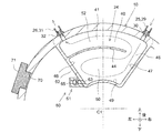
- FIG. 1 is a vertical sectional side view showing the structure of the end portion of the internal combustion engine.
- FIG. 2 is a schematic longitudinal rear view showing the heating chamber.
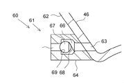
- FIG. 3 is a schematic longitudinal rear view showing the drain mechanism.
- FIG. 4 is a schematic longitudinal rear view for explaining a working method at the time of oil discharge.
- FIG. 5 is a schematic longitudinal rear view showing a drain mechanism according to a first modification.
- FIG. 6 is a schematic longitudinal rear view showing a drain mechanism according to a second modification.
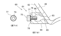
- 7A and 7B show a drain mechanism according to a third modified example.
- FIG. 7A is a left side view of a drain bolt
- FIG. 7B is a schematic vertical sectional rear view.
- 8A and 8B show a drain mechanism of a fourth modified example, where FIG. 8A is a left side view of a drain bolt, and FIG. 8B is a schematic longitudinal rear view.
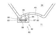
- FIG. 9 is a schematic longitudinal rear view showing a drain mechanism according to a
- FIG. 1 is a side sectional view showing the structure of the end of the internal combustion engine according to this embodiment.
- the internal combustion engine (engine) 1 is a diesel engine mounted on a vehicle (not shown), and the vehicle is a large vehicle such as a truck.
- the type and use of the vehicle and the engine are not particularly limited.
- the vehicle may be a small vehicle such as a passenger car, or the engine may be a gasoline engine.
- the engine is installed vertically in the vehicle. The front, rear, left, right, up, and down directions of the vehicle and the engine are as illustrated.
- the engine 1 includes a cylinder block 2 integrally having a crankcase (not shown), a cylinder head 3 fastened to an upper end of the cylinder block 2, a head cover 4 fastened to an upper end of the cylinder head 3, a crank, And an oil pan 5 fastened to the lower end of the case.
- a crankshaft 6 is rotatably supported by the crankcase, and a camshaft 7 is rotatably supported by the cylinder head 3.
- a flywheel 8 is attached to a rear end surface of the crankshaft 6 by a plurality of bolts 9.
- a flywheel housing 10 that accommodates the flywheel 8 is attached to the cylinder block 2 with bolts or the like (not shown).
- the flywheel housing 10 may be formed integrally with the cylinder block 2. Inside the flywheel housing 10, there is formed a cylindrical flywheel chamber 11 for accommodating the flywheel 8 substantially rotatably.
- a clutch device (not shown) is connected to the rear end of the flywheel housing 10, and a clutch input shaft of the clutch device is coaxially connected to the crankshaft 6.
- a part of the oil pan 5 is attached to the flywheel housing 10 with bolts 12.
- a mechanism chamber is formed between the rear end face of the cylinder block 2 and the flywheel housing 10, and a power transmission mechanism for transmitting power from the crankshaft 6 to the camshaft 7 is housed in the mechanism chamber.
- the power transmission mechanism is formed by a gear mechanism 13 configured by meshing a plurality of gears
- the mechanism chamber is formed by a gear chamber 14.
- the type of the power transmission mechanism is arbitrary, and may be formed by, for example, a chain mechanism.
- the gear mechanism 13 includes a crank gear 15 fixed to the crankshaft 6, a cam gear 16 fixed to the camshaft 7, and a plurality (two in the present embodiment) interposed between the crank gear 15 and the cam gear 16. Intermediate gears 17A, 17B.
- the gear chamber 14 is communicated with a crank chamber 18 in the crank case, a valve operating chamber 3A on the cylinder head 3, and a cover chamber 19 in the head cover 4.
- C1 indicates the central axis of the crankshaft 6, and C2 indicates the central axis of the camshaft 7, respectively.
- a gear chamber partition wall 20 having a half-width frame shape (U-shape) in a plan view is integrally formed, and a space inside the gear chamber partition wall 20 is one of the gear chambers 14. Department.
- the upper end surface of the flywheel housing 10 is in close contact with the lower end surface of the gear chamber partition wall 20, and the lower end surface of the head cover 4 is in close contact with the upper end surface of the gear chamber partition wall 20.
- the rear end of the crankshaft 6 protrudes into the rear flywheel chamber 11 through an insertion hole 21 provided in the flywheel housing 10.
- a seal member (not shown) for preventing oil or gas from leaking from the gear chamber 14 is provided around the insertion hole 21.
- blow-by gas leaks from the combustion chamber in the cylinder into the crank chamber 18 through the gap between the piston ring and the cylinder bore.
- the blow-by gas is introduced into the cover chamber 19 through the gear chamber 14 and other gas passage holes.
- an oil separator 22 for separating oil from blow-by gas is formed in the cover chamber 19.
- a meandering passage for flowing blow-by gas is formed in the oil separator 22.
- the blow-by gas after the oil is separated by the oil separator 22 is discharged to the atmosphere through a gas pipe 23 serving as a blow-by gas pipe.
- the gas pipe 23 is exposed to the outside air and is directly cooled by the outside air.
- the gas pipe 23 of the present embodiment is formed of a metal such as stainless steel, and is entirely exposed to the outside air, and is easily cooled by the outside air.
- the blow-by gas passing through the gas pipe 23 is also cooled, and condensed water due to the blow-by gas is generated in the gas pipe 23. If the outside air temperature is below the freezing point in a cold area, for example, the condensed water may freeze and block the gas pipe 23. If the inside of the gas pipe 23 is closed, there is a possibility that discharge of blow-by gas may be hindered.
- a heating chamber 24 for heating the blow-by gas is provided in the middle of the gas pipe 23, and the blow-by gas is heated in the heating chamber 24, thereby generating condensed water caused by the blow-by gas, The freezing is suppressed.
- the heating chamber 24 is formed in the flywheel housing 10 and is adjacent to the gear chamber 14 with a partition wall (a lid 41 described later in the present embodiment) interposed therebetween, and mainly receives heat received from oil in the gear chamber 14.
- the blow-by gas is heated.
- the blow-by gas can be efficiently heated without providing a dedicated heat source.
- the gas pipe 23 extends from the upper end of the engine 1 to the lower end of the engine 1 as a whole. However, the gas pipe 23 is divided into two parts at an intermediate position in the height direction, and is divided into an upstream gas pipe 25 and a downstream gas pipe 26 (shown by phantom lines in FIG. 1).
- the heating chamber 24 is connected between the upstream gas pipe 25 and the downstream gas pipe 26.
- Each of the upstream gas pipe 25 and the downstream gas pipe 26 is formed of a metal such as stainless steel, and is exposed to the outside air outside the engine.
- the inlet 27 of the upstream gas pipe 25 is connected to the oil separator 22.
- the head cover 4 is provided with an outlet 28 for extracting the blow-by gas after oil separation from the oil separator 22, and the inlet 27 of the upstream gas pipe 25 is connected to the outlet 28.
- the inlet 27 of the upstream gas pipe 25 forms an inlet of the gas pipe 23. Since the head cover 4 and the oil separator 22 are provided at the height of the upper end of the engine 1 and the inlet 27 of the upstream gas pipe 25 is connected to the oil separator 22, the gas pipe 23 It will extend downstream from the height position of the upper end.
- the oil separator 22 may be provided outside the head cover 4 instead of inside.
- Reference numeral 22 ⁇ / b> A in the figure indicates a partition wall that partitions the oil separator 22.
- the outlet 29 of the upstream gas pipe 25 is connected to the heating chamber 24.
- An inlet 30 for introducing blow-by gas into the heating chamber 24 is provided at an upper end and a right end of the heating chamber 24, and an outlet 29 of the upstream gas pipe 25 is connected to the inlet 30. .
- the inlet 31 of the downstream gas pipe 26 is also connected to the heating chamber 24.
- An outlet 32 for discharging blow-by gas from the heating chamber 24 is provided at the upper end and the left end of the heating chamber 24, and the inlet 31 of the downstream gas pipe 26 is connected to the outlet 32. .
- the downstream gas pipe 26 passes through the left side of the flywheel housing 10 and extends downward toward the downstream side.
- the outlet 33 of the downstream gas pipe 26 is disposed at the height of the lower end of the engine 1 and is open to the atmosphere in a downward direction.
- the outlet 33 of the downstream gas pipe 26 forms an outlet of the gas pipe 23.
- the gas pipe 23 extends to the level of the lower end of the engine 1.
- the heating chamber 24 is formed inside the flywheel housing 10 and at the upper end.
- the heating chamber 24 is mainly defined by a cavity 40 formed in the flywheel housing 10 and opening forward, and a lid 41 closing a front end opening of the cavity 40.
- the flywheel housing 10 is cast from aluminum or iron
- the lid 41 is formed from any metal plate.
- the material of the lid 41 is excellent in heat resistance and corrosion resistance and has relatively high thermal conductivity, for example, aluminum or stainless steel.
- the lid 41 is overlaid on the lid mounting surface 42 of the flywheel housing 10 located around the front end opening of the cavity 40, and is detachably and air-tightly fixed by a plurality of bolts 43.
- the heating chamber 24 of the present embodiment has a fan shape or a substantially fan shape extending around the crankshaft center axis C1 when viewed from the rear (that is, one end side in the direction of the crankshaft center axis C1). Have been. The same applies to the rear view shape of the lid 41.
- An inlet 30 is provided on the right side of the upper end of the heating chamber 24, and a discharge port 32 is provided on the left side of the upper end.
- the central axes of the inlet 30 and the outlet 32 are substantially along the radial direction with respect to the crankshaft central axis C1.
- a partition wall 44 that forms a meandering passage in the heating chamber 24 is provided inside the heating chamber 24.
- the partition wall 44 is formed integrally with the flywheel housing 10. As shown in FIG. 1, the partition wall 44 integrally and linearly protrudes forward from the rear inner wall surface 45 of the heating chamber 24, which is the bottom surface of the cavity 40, and comes into contact with the lid 41 in a gas-tight manner. The space in the room 24 is vertically divided. As shown in FIG. 2, the partition wall 44 extends integrally and in an arc shape from the left inner wall surface 46 of the heating chamber 24, which is one side surface of the cavity 40, to the right side. It terminates at a position where a predetermined gap 48 is formed between itself and the right inner wall surface 47 of the chamber 24.
- the outlet of the inlet 30 is directed toward the gap 48 and, consequently, the lower inner wall surface 49 of the heating chamber 24.
- the inlet 30 can send the blow-by gas discharged from the inlet 30 straight through the gap 48 to the space 50 below the partition wall 44, as indicated by the arrow.
- the heating chamber 24 and the flywheel chamber 11 overlap in the vertical direction, and the lower end of the heating chamber 24 is disposed in front of the upper end of the flywheel chamber 11.
- a step 51 projecting forward is provided on a rear inner wall surface 45 of the heating chamber 24.
- the shape of the heating chamber 24 is not limited to the above-mentioned shape, and can be changed to any shape.
- a plurality of partition walls 44 may be provided instead of one as in the present embodiment. If possible, the step 51 may not be provided.
- the blow-by gas after the oil is separated by the oil separator 22 is sent to the heating chamber 24. Therefore, the oil content of the blow-by gas in the heating chamber 24 is relatively small. However, even after a long period of time, an unacceptable amount of oil may accumulate in the heating chamber 24.
- a drain mechanism 60 for discharging oil accumulated in the heating chamber 24 is provided in the heating chamber 24. Accordingly, the oil accumulated in the heating chamber 24 can be discharged, and a problem caused by the accumulated oil (for example, obstructing a desired flow of blow-by gas in the heating chamber 24) can be solved.
- the drain mechanism 60 is provided at the lowest position of the heating chamber 24, specifically, at the lower left corner, so that the oil accumulated in the heating chamber 24 can be discharged as much as possible. Has become.
- the drain mechanism 60 includes a drain valve that can be opened and closed. The drain valve prohibits oil discharge when the valve is closed and allows oil discharge when the valve is opened.
- the drain valve is formed by the check valve 61.
- a horizontal drain hole 63 that penetrates the left wall 62 is provided at the lowest position of the left wall 62 that forms the left inner wall 46 of the heating chamber 24.
- a check valve 61 is attached to the outer surface of the left side wall portion 62 by appropriate means such as welding or bolting so as to communicate with the drain hole 63.
- the check valve 61 includes a valve body 64 attached to the left side wall portion 62, a valve hole 65 formed through the valve body 64, and a valve body chamber 66 formed with an enlarged diameter in the middle of the valve hole 65.
- the valve includes a valve body 67 disposed in the valve body chamber 66 and a spring 68 as an urging member for urging the valve body 67 toward the valve closing side.
- the valve hole 65 communicates coaxially with the drain hole 63 and extends horizontally and horizontally.
- the valve body 67 is formed of a metal ball such as an iron ball.
- the spring 68 urges the valve body 67 to the left side on the side opposite to the heating chamber 24 to press the valve body 67 against the valve seat 69 to close the check valve 61. Accordingly, in the illustrated example, the left side, which is the side opposite to the heating chamber 24, is the valve closing side, and the right side, which is the heating chamber 24 side, is the valve opening side.
- the spring 68 is formed by a coil spring.
- the check valve 61 is accessible through a hole provided in the flywheel housing 10, that is, a housing hole 70.
- the housing hole 70 is a service hole for visually confirming the inside of the flywheel housing 10 after assembling, and is normally closed by a detachable plug 71 such as a screw-in type. By removing the plug 71, the check valve 61 becomes accessible from outside the flywheel housing 10.
- the valve hole 65 is directed to a housing hole 70 on the left side thereof.
- the flow of the blow-by gas in the configuration of the present embodiment is as shown by arrows in FIGS. 1 and 2.
- the blow-by gas from which oil has been separated by the oil separator 22 flows into the heating chamber 24 through the upstream gas pipe 25 and the inlet 30.
- the blow-by gas discharged from the inlet 30 linearly and smoothly enters the lower space 50 through the gap 48.
- the blow-by gas once proceeds to the left in the lower space 50, makes a U-turn to the right, rises in the gap 48, and enters the upper space 52 partitioned by the partition wall 44.
- the gas is discharged from the outlet 32 into the downstream gas pipe 26.
- the blow-by gas flows through the downstream gas pipe 26 and is discharged to the outside air (that is, released to the atmosphere) through the outlet 33.
- the blow-by gas can meander in the heating chamber 24 to temporarily stay therein.
- relatively high temperature oil in the gear chamber 14 for lubricating the gear mechanism 13 is attached to the flywheel housing 10 and the lid 41, and the flywheel housing 10 and the lid 41 are heated by the oil. Therefore, the heat can heat the blow-by gas in the heating chamber 24 to keep the temperature or at least suppress the temperature drop. Therefore, it is possible to suppress the generation of condensed water due to the condensation of the moisture contained in the blow-by gas, the freezing of the condensed water in the gas pipe 23, and the blocking of the gas pipe 23 due to the freezing. Since the blow-by gas meanders and stays in the heating chamber 24, the heating time can be increased, which is advantageous for suppressing the generation of condensed water and the like.
- the blow-by gas is cooled by the outside air and tends to decrease its temperature toward the downstream side in the gas pipe 23 exposed to the outside air.
- the most severe is the outlet 33 of the downstream gas pipe 26, where the temperature of the blow-by gas is the lowest.
- the outside air including the traveling wind enters the exit portion 33, and the outside air entering the exit portion 33 has a very low temperature in a cold region or the like. Under these circumstances, condensed water and freezing are likely to occur inside the outlet portion 33.
- the blow-by gas can be heated in the heating chamber 24 in the middle of the gas pipe 23 because the temperature of the blow-by gas when reaching the outlet 33 is increased, and the temperature of the outlet 33 is increased. It is possible to effectively suppress the generation and freezing of condensed water inside.
- the heating chamber 24 is formed by the cavity 40 integrally formed with the flywheel housing 10 and the lid 41 for closing the same, the complete closed space is formed inside the flywheel housing.
- the formation of the heating chamber can be facilitated as compared with the case where a certain heating chamber is formed.
- the lid 41 is detachable, the inside of the heating chamber 24 can be inspected and maintained by removing the lid 41 if necessary.
- the lid 41 can be regarded as a part of the divided flywheel housing 10.
- a heating chamber which is a completely closed space may be formed inside the flywheel housing.
- the maintenance person when discharging the oil O accumulated in the heating chamber 24, the maintenance person removes the plug 71 and inserts a jig or a tool 72 into the flywheel housing 10 through the housing hole 70. Then, the tip of the tool 72 is inserted into the valve hole 65, the tool 72 is pushed toward the valve opening side (right side), and the valve body 67 is pushed out at the tip of the tool 72 against the urging force of the spring 68 toward the valve opening side. Is opened.
- the oil O is discharged from the heating chamber 24 through the drain hole 63 and the valve hole 65 in this order.
- the discharged oil O is dropped into the flywheel housing 10, but there is no problem because the inside of the flywheel housing 10 is also in an oil atmosphere and the amount of oil is very small.
- the oil can be periodically discharged at a time when the maintenance is performed, and the oil accumulation can be suppressed. Can be solved. Further, since the oil can be discharged only by inserting the tool 72 through the housing hole 70 and pushing the valve body 67 at the tip of the tool 72, the oil discharging operation can be performed very easily.
- valve body 67 of the check valve 61 is formed by a hollow piston having a bottomed cylindrical shape.
- One end on the left side of the valve body 67 is closed and pressed against a valve seat 69 by a spring 68.
- the other end on the right side of the valve body 67 is opened, from which a spring 68 is inserted into the valve body 67.
- the drain valve is formed by the drain bolt 75.
- the drain bolt 75 is fastened to a female screw 76 provided on the inner surface of the outlet of the valve hole 65 to close the valve hole 65. As a result, the drain valve is closed.
- the drain bolt 75 is formed by a general hexagonal bolt having a hexagonal head 77 and is fastened to the female screw 76 with a washer 78 interposed therebetween.
- the drain bolt 75 is loosened, the oil leaks out from the gap between the drain bolt 75 and the female screw 76 and is discharged, so that the valve hole 65 is substantially opened and the drain valve is opened.
- the drain bolt 75 is brought into the valve closed state and the valve open state by tightening and loosening, and can be regarded as a drain valve.
- a socket wrench (not shown) is inserted into the flywheel housing 10 through the housing hole 70, and the socket of the socket wrench is fitted to the head 77. Then, by turning the socket wrench to loosen the drain bolt 75, the drain valve is opened and the oil is discharged.
- the drain bolt 75 is formed by a general hexagonal bolt having a hexagonal hole 79.
- a hexagon wrench is inserted through the housing hole 70, and the drain bolt 75 is loosened by the hexagon wrench.
- the drain bolt 75 is formed by a hexagon socket head bolt.
- a groove 81 extending in the axial direction is formed in the male screw portion 80 of the drain bolt 75.
- the female screw 76 is loosened by loosening the drain bolt 75 so that the groove 81 extends from a position on the heating chamber 24 side of the female screw 76 to a position on the opposite side of the heating chamber 24 from the female screw 76.
- the shortcut is to drain the oil quickly.
- the groove 81 can be applied to any drain bolt including the drain bolt 75 of the second modification (FIG. 6).
- the drain mechanism 60 is formed by a check valve 82, but this check valve 82 is not a spring type as in the basic embodiment (FIG. 3) but a gravity type.
- valve element 83 of the check valve 82 is seated on the valve seat 84 by its own weight when the engine is stopped, and closes the check valve 82.
- the valve element 83 rises as indicated by the phantom line due to the pressure in the flywheel chamber 11 that has risen due to the rotation of the flywheel 8, separates from the valve seat 84, and opens the check valve 82. .
- oil can be discharged during engine operation.
- a vertical drain hole 86 penetrating the lower wall portion 85 is provided at the lowest position of the lower wall portion 85 forming the lower inner wall surface 49 of the heating chamber 24.
- a check valve 82 is attached to the outer surface of the lower side wall 85 by appropriate means such as welding or bolting so as to communicate with the drain hole 86.
- the check valve 82 includes a valve body 87 attached to the lower side wall portion 85, a valve hole 88 formed through the valve body 87, and a valve body chamber 89 formed with an enlarged diameter in the middle of the valve hole 88. And a valve element 83 disposed in the valve element chamber 89 so as to be able to move up and down.
- the valve hole 88 extends coaxially with the drain hole 86 in the vertical direction.
- the valve element 83 is formed in a disk shape.
- the valve seat 84 and the lower peripheral edge of the valve body 83 seated thereon are formed in a tapered shape.
- the oil separator 22 may be omitted. In this case, the oil stays in the heating chamber 24 at a higher speed, but the staying oil can be discharged by the drain mechanism.
- the installation position of the drain mechanism can be changed to a position other than the above.
- freezing of condensed water in the blow-by gas pipe can be suppressed.
Abstract
This blow-by gas discharging device is provided with: a blow-by gas pipe 23 that extends from the upper end height position to the lower end height position of an internal combustion engine 1 and that has an outlet 33 exposed to outside air and opened to the atmosphere; a heating chamber 24 that is provided to the midway of the blow-by gas pipe, and formed in a flywheel housing 10 of the internal combustion engine so as to heat a blow-by gas; and a drain mechanism that is provided to the heating chamber so as to discharge oil accumulated in the heating chamber.
Description
本開示はブローバイガス排出装置に係り、特に、外気に露出されたブローバイガス配管を通じてブローバイガスを大気に排出する装置に関する。
The present disclosure relates to a blow-by gas discharge device, and more particularly, to a device that discharges blow-by gas to the atmosphere through a blow-by gas pipe exposed to outside air.
内燃機関のクランク室内に発生したブローバイガスは、通常、吸気系に環流されると共に燃焼室内に送られ、燃焼室内で混合気と一緒に燃焼させられる。
The blow-by gas generated in the crank chamber of the internal combustion engine is usually returned to the intake system and sent to the combustion chamber, where it is burned together with the air-fuel mixture in the combustion chamber.
一方、ブローバイガスを吸気系に環流させる代わりに大気に排出する装置も知られている(例えば特許文献1参照)。この場合、内燃機関の上端部の高さ位置から下端部の高さ位置まで、外気に露出したブローバイガス配管を設け、このブローバイガス配管を通じてブローバイガスを大気に排出することが考えられる。
On the other hand, there is also known a device that discharges blow-by gas to the atmosphere instead of circulating it to an intake system (for example, see Patent Document 1). In this case, it is conceivable that a blow-by gas pipe exposed to the outside air is provided from the height position of the upper end portion to the height position of the lower end portion of the internal combustion engine, and the blow-by gas is discharged to the atmosphere through the blow-by gas pipe.
しかしこうした場合、ブローバイガス配管が外気で冷却されることから、配管内を通じるブローバイガスも冷却され、配管内にブローバイガスに起因した凝縮水が発生する。外気温が氷点下以下の場合だと、この凝縮水が凍結して配管内を閉塞する可能性がある。
However, in such a case, since the blow-by gas pipe is cooled by the outside air, the blow-by gas passing through the pipe is also cooled, and condensed water due to the blow-by gas is generated in the pipe. If the outside air temperature is below the freezing point, the condensed water may freeze and block the piping.
本開示は、ブローバイガス配管内での凝縮水の凍結を抑制できるブローバイガス排出装置を提供する。
The present disclosure provides a blow-by gas discharge device that can suppress freezing of condensed water in a blow-by gas pipe.
本開示の一の態様によれば、ブローバイガス排出装置は、
内燃機関の上端部の高さ位置から下端部の高さ位置まで延在され、外気に露出されると共に、大気解放された出口部を有するブローバイガス配管と、
前記ブローバイガス配管の途中に介設され、前記内燃機関のフライホイールハウジングに形成されると共に、ブローバイガスを加熱する加熱室と、
前記加熱室に設けられ、前記加熱室に堆積したオイルを排出するためのドレン機構と、
を備える。 According to one aspect of the present disclosure, the blow-by gas exhaust device includes:
A blow-by gas pipe that extends from the height position of the upper end portion of the internal combustion engine to the height position of the lower end portion, is exposed to the outside air, and has an outlet that is open to the atmosphere,
A heating chamber that is provided in the middle of the blow-by gas pipe and is formed in a flywheel housing of the internal combustion engine, and heats a blow-by gas,
A drain mechanism provided in the heating chamber, for discharging oil deposited in the heating chamber,
Is provided.
前記ドレン機構は、閉弁時にオイルの排出を禁止し、開弁時にオイルの排出を許容するドレンバルブを備えてもよい。
The drain mechanism may include a drain valve that prohibits oil discharge when the valve is closed and allows oil discharge when the valve is opened.
前記ドレンバルブは、チェックバルブにより形成され、前記チェックバルブは、弁体と、前記弁体を閉弁側に付勢する付勢部材とを有してもよい。
The drain valve may be formed by a check valve, and the check valve may have a valve element and an urging member for urging the valve element to the valve closing side.
前記ドレンバルブは、ドレンボルトにより形成されてもよい。
The drain valve may be formed by a drain bolt.
前記ドレンバルブは、前記フライホイールハウジングに設けられた穴を通じてアクセス可能に構成されても良い。
The drain valve may be configured to be accessible through a hole provided in the flywheel housing.
本開示によれば、ブローバイガス配管内での凝縮水の凍結を抑制できる。
According to the present disclosure, freezing of condensed water in the blow-by gas pipe can be suppressed.
以下、添付図面を参照して本開示の実施形態を説明する。なお本開示は以下の実施形態に限定されない点に留意されたい。
Hereinafter, embodiments of the present disclosure will be described with reference to the accompanying drawings. Note that the present disclosure is not limited to the following embodiments.
図1は、本実施形態に係る内燃機関の端部の構造を示す側面断面図である。内燃機関(エンジン)1は車両(図示せず)に搭載されたディーゼルエンジンであり、車両はトラック等の大型車両である。但し車両およびエンジンの種類、用途等に特に限定はなく、例えば車両は乗用車等の小型車両であってもよいし、エンジンはガソリンエンジンであってもよい。エンジンは車両に縦置きされている。車両およびエンジンの前後左右上下の各方向は図示する通りである。
FIG. 1 is a side sectional view showing the structure of the end of the internal combustion engine according to this embodiment. The internal combustion engine (engine) 1 is a diesel engine mounted on a vehicle (not shown), and the vehicle is a large vehicle such as a truck. However, the type and use of the vehicle and the engine are not particularly limited. For example, the vehicle may be a small vehicle such as a passenger car, or the engine may be a gasoline engine. The engine is installed vertically in the vehicle. The front, rear, left, right, up, and down directions of the vehicle and the engine are as illustrated.
エンジン1は、クランクケース(図示せず)を一体に有するシリンダブロック2と、シリンダブロック2の上端部に締結されたシリンダヘッド3と、シリンダヘッド3の上端部に締結されたヘッドカバー4と、クランクケースの下端部に締結されたオイルパン5とを有する。クランクケースにはクランクシャフト6が回転可能に支持され、シリンダヘッド3にはカムシャフト7が回転可能に支持されている。
The engine 1 includes a cylinder block 2 integrally having a crankcase (not shown), a cylinder head 3 fastened to an upper end of the cylinder block 2, a head cover 4 fastened to an upper end of the cylinder head 3, a crank, And an oil pan 5 fastened to the lower end of the case. A crankshaft 6 is rotatably supported by the crankcase, and a camshaft 7 is rotatably supported by the cylinder head 3.
クランクシャフト6の後端面部にはフライホイール8が複数のボルト9により取り付けられている。このフライホイール8を収容するフライホイールハウジング10が、シリンダブロック2に図示しないボルト等により取り付けられている。なおフライホイールハウジング10はシリンダブロック2に一体形成されてもよい。フライホイールハウジング10の内部には、フライホイール8を実質的に回転可能に収容する円筒状のフライホイール室11が形成されている。フライホイールハウジング10の後端部には図示しないクラッチ装置が接続され、クラッチ装置のクラッチ入力軸がクランクシャフト6に同軸連結される。オイルパン5の一部がフライホイールハウジング10にボルト12で取り付けられる。
フ ラ イ A flywheel 8 is attached to a rear end surface of the crankshaft 6 by a plurality of bolts 9. A flywheel housing 10 that accommodates the flywheel 8 is attached to the cylinder block 2 with bolts or the like (not shown). The flywheel housing 10 may be formed integrally with the cylinder block 2. Inside the flywheel housing 10, there is formed a cylindrical flywheel chamber 11 for accommodating the flywheel 8 substantially rotatably. A clutch device (not shown) is connected to the rear end of the flywheel housing 10, and a clutch input shaft of the clutch device is coaxially connected to the crankshaft 6. A part of the oil pan 5 is attached to the flywheel housing 10 with bolts 12.
シリンダブロック2の後端面部とフライホイールハウジング10の間には機構室が形成され、この機構室には、クランクシャフト6からカムシャフト7まで動力を伝達する動力伝達機構が収容される。本実施形態の場合、動力伝達機構は、複数の歯車を噛合させて構成されたギヤ機構13により形成され、機構室はギヤ室14により形成される。しかしながら、動力伝達機構の種類は任意であり、例えばチェーン機構により形成されてもよい。ギヤ機構13は、クランクシャフト6に固定されたクランクギヤ15と、カムシャフト7に固定されたカムギヤ16と、これらクランクギヤ15およびカムギヤ16の間に介在された複数(本実施形態では二つ)の中間ギヤ17A、17Bとを有する。ギヤ室14は、クランクケース内のクランク室18と、シリンダヘッド3上の動弁室3Aと、ヘッドカバー4内のカバー室19とに連通される。
A mechanism chamber is formed between the rear end face of the cylinder block 2 and the flywheel housing 10, and a power transmission mechanism for transmitting power from the crankshaft 6 to the camshaft 7 is housed in the mechanism chamber. In the case of the present embodiment, the power transmission mechanism is formed by a gear mechanism 13 configured by meshing a plurality of gears, and the mechanism chamber is formed by a gear chamber 14. However, the type of the power transmission mechanism is arbitrary, and may be formed by, for example, a chain mechanism. The gear mechanism 13 includes a crank gear 15 fixed to the crankshaft 6, a cam gear 16 fixed to the camshaft 7, and a plurality (two in the present embodiment) interposed between the crank gear 15 and the cam gear 16. Intermediate gears 17A, 17B. The gear chamber 14 is communicated with a crank chamber 18 in the crank case, a valve operating chamber 3A on the cylinder head 3, and a cover chamber 19 in the head cover 4.
C1はクランクシャフト6の中心軸、C2はカムシャフト7の中心軸をそれぞれ示す。
C1 indicates the central axis of the crankshaft 6, and C2 indicates the central axis of the camshaft 7, respectively.
シリンダヘッド3の後端部には、平面視で半角枠状(コ字状)のギヤ室区画壁20が一体に突出形成され、このギヤ室区画壁20の内側の空間がギヤ室14の一部とされる。ギヤ室区画壁20の下端面にフライホイールハウジング10の上端面が密接され、ギヤ室区画壁20の上端面にヘッドカバー4の下端面が密接される。
At the rear end of the cylinder head 3, a gear chamber partition wall 20 having a half-width frame shape (U-shape) in a plan view is integrally formed, and a space inside the gear chamber partition wall 20 is one of the gear chambers 14. Department. The upper end surface of the flywheel housing 10 is in close contact with the lower end surface of the gear chamber partition wall 20, and the lower end surface of the head cover 4 is in close contact with the upper end surface of the gear chamber partition wall 20.
クランクシャフト6の後端部は、フライホイールハウジング10に設けられた挿通穴21を通じて後方のフライホイール室11内に突出される。挿通穴21の周辺部には、ギヤ室14からのオイルやガスの漏出を防止するためのシール部材(図示せず)が設けられる。
The rear end of the crankshaft 6 protrudes into the rear flywheel chamber 11 through an insertion hole 21 provided in the flywheel housing 10. A seal member (not shown) for preventing oil or gas from leaking from the gear chamber 14 is provided around the insertion hole 21.
周知のように、シリンダ内の燃焼室から、ピストンリングとシリンダボアの隙間を通じて、クランク室18内にブローバイガスが漏出する。このブローバイガスは、ギヤ室14や他のガス通過穴を通じてカバー室19内に導入される。
As is well known, blow-by gas leaks from the combustion chamber in the cylinder into the crank chamber 18 through the gap between the piston ring and the cylinder bore. The blow-by gas is introduced into the cover chamber 19 through the gear chamber 14 and other gas passage holes.
一方、カバー室19内には、ブローバイガスからオイルを分離するオイルセパレータ22が形成されている。図示しないがオイルセパレータ22内には、ブローバイガスを流す蛇行通路が形成されている。本実施形態の場合、オイルセパレータ22でオイルが分離された後のブローバイガスが、ブローバイガス配管としてのガス管23を通じて大気に排出されるようになっている。
On the other hand, an oil separator 22 for separating oil from blow-by gas is formed in the cover chamber 19. Although not shown, a meandering passage for flowing blow-by gas is formed in the oil separator 22. In the case of the present embodiment, the blow-by gas after the oil is separated by the oil separator 22 is discharged to the atmosphere through a gas pipe 23 serving as a blow-by gas pipe.
ガス管23は、外気に露出され、外気によって直接的に冷却される。特に本実施形態のガス管23は、ステンレス等の金属によって形成されると共に、その全体が外気に露出され、外気によって冷却され易い。こうなると、ガス管23内を通じるブローバイガスも冷却され、ガス管23内にブローバイガスに起因した凝縮水が発生する。そして例えば寒冷地等で、外気温が氷点下以下の場合だと、凝縮水が凍結してガス管23内を閉塞する可能性がある。ガス管23内が閉塞されると、ブローバイガスの排出に支障を来す虞がある。
The gas pipe 23 is exposed to the outside air and is directly cooled by the outside air. In particular, the gas pipe 23 of the present embodiment is formed of a metal such as stainless steel, and is entirely exposed to the outside air, and is easily cooled by the outside air. When this happens, the blow-by gas passing through the gas pipe 23 is also cooled, and condensed water due to the blow-by gas is generated in the gas pipe 23. If the outside air temperature is below the freezing point in a cold area, for example, the condensed water may freeze and block the gas pipe 23. If the inside of the gas pipe 23 is closed, there is a possibility that discharge of blow-by gas may be hindered.
そこで本実施形態では、ガス管23の途中に、ブローバイガスを加熱する加熱室24を介設し、加熱室24内でブローバイガスを加熱することにより、ブローバイガスに起因した凝縮水の発生と、その凍結を抑制するようにしている。特に加熱室24は、フライホイールハウジング10に形成されると共に、ギヤ室14に隔壁(本実施形態では後述の蓋41)を隔てて隣接され、主にギヤ室14内のオイルから受け取った熱によりブローバイガスを加熱するようになっている。これにより専用の熱源を設けることなく、ブローバイガスを効率的に加熱することができる。以下、こうしたブローバイガス排出装置の構成を詳細に説明する。
Therefore, in the present embodiment, a heating chamber 24 for heating the blow-by gas is provided in the middle of the gas pipe 23, and the blow-by gas is heated in the heating chamber 24, thereby generating condensed water caused by the blow-by gas, The freezing is suppressed. In particular, the heating chamber 24 is formed in the flywheel housing 10 and is adjacent to the gear chamber 14 with a partition wall (a lid 41 described later in the present embodiment) interposed therebetween, and mainly receives heat received from oil in the gear chamber 14. The blow-by gas is heated. Thus, the blow-by gas can be efficiently heated without providing a dedicated heat source. Hereinafter, the configuration of such a blow-by gas discharge device will be described in detail.
ガス管23は、全体として、エンジン1の上端部の高さ位置から下端部の高さ位置まで延在される。但しガス管23は、高さ方向の途中の位置で二分割され、上流側ガス管25と下流側ガス管26(図1には仮想線で示す)とに分けられる。これら上流側ガス管25と下流側ガス管26の間に加熱室24が接続される。上流側ガス管25と下流側ガス管26は、いずれもステンレス等の金属によって形成され、エンジン外部にて外気に露出されている。
The gas pipe 23 extends from the upper end of the engine 1 to the lower end of the engine 1 as a whole. However, the gas pipe 23 is divided into two parts at an intermediate position in the height direction, and is divided into an upstream gas pipe 25 and a downstream gas pipe 26 (shown by phantom lines in FIG. 1). The heating chamber 24 is connected between the upstream gas pipe 25 and the downstream gas pipe 26. Each of the upstream gas pipe 25 and the downstream gas pipe 26 is formed of a metal such as stainless steel, and is exposed to the outside air outside the engine.
上流側ガス管25の入口部27はオイルセパレータ22に接続される。ヘッドカバー4には、オイルセパレータ22からオイル分離後のブローバイガスを取り出すための取出口28が設けられ、上流側ガス管25の入口部27はこの取出口28に接続されている。上流側ガス管25の入口部27は、ガス管23の入口部をなすものである。ヘッドカバー4およびオイルセパレータ22がエンジン1の上端部の高さ位置に設けられ、そのオイルセパレータ22に上流側ガス管25の入口部27が接続されていることから、ガス管23は、エンジン1の上端部の高さ位置から下流側に向かって延在することとなる。
入口 The inlet 27 of the upstream gas pipe 25 is connected to the oil separator 22. The head cover 4 is provided with an outlet 28 for extracting the blow-by gas after oil separation from the oil separator 22, and the inlet 27 of the upstream gas pipe 25 is connected to the outlet 28. The inlet 27 of the upstream gas pipe 25 forms an inlet of the gas pipe 23. Since the head cover 4 and the oil separator 22 are provided at the height of the upper end of the engine 1 and the inlet 27 of the upstream gas pipe 25 is connected to the oil separator 22, the gas pipe 23 It will extend downstream from the height position of the upper end.
なお、オイルセパレータ22はヘッドカバー4の内部ではなく外部に設けられてもよい。図中の符号22Aは、オイルセパレータ22を区画する区画壁を示す。
The oil separator 22 may be provided outside the head cover 4 instead of inside. Reference numeral 22 </ b> A in the figure indicates a partition wall that partitions the oil separator 22.
他方、図2にも示すように、上流側ガス管25の出口部29は加熱室24に接続される。加熱室24の上端部で且つ右端部には、加熱室24にブローバイガスを導入するための導入口30が設けられ、上流側ガス管25の出口部29はこの導入口30に接続されている。
On the other hand, as shown in FIG. 2, the outlet 29 of the upstream gas pipe 25 is connected to the heating chamber 24. An inlet 30 for introducing blow-by gas into the heating chamber 24 is provided at an upper end and a right end of the heating chamber 24, and an outlet 29 of the upstream gas pipe 25 is connected to the inlet 30. .
また、下流側ガス管26の入口部31も加熱室24に接続される。加熱室24の上端部で且つ左端部には、加熱室24からブローバイガスを排出するための排出口32が設けられ、下流側ガス管26の入口部31はこの排出口32に接続されている。
(4) The inlet 31 of the downstream gas pipe 26 is also connected to the heating chamber 24. An outlet 32 for discharging blow-by gas from the heating chamber 24 is provided at the upper end and the left end of the heating chamber 24, and the inlet 31 of the downstream gas pipe 26 is connected to the outlet 32. .
他方、図1に示すように、下流側ガス管26は、下流側に向かうにつれ、フライホイールハウジング10の左側方を通過して下方に延びる。そして下流側ガス管26の出口部33は、エンジン1の下端部の高さ位置に配置されると共に、下向きの状態で大気解放されている。これにより、出口部33から排出されたブローバイガスでエンジンが汚損されるのを抑制できる。下流側ガス管26の出口部33は、ガス管23の出口部をなすものである。このため、ガス管23はエンジン1の下端部の高さ位置まで延在されることとなる。
On the other hand, as shown in FIG. 1, the downstream gas pipe 26 passes through the left side of the flywheel housing 10 and extends downward toward the downstream side. The outlet 33 of the downstream gas pipe 26 is disposed at the height of the lower end of the engine 1 and is open to the atmosphere in a downward direction. Thus, the engine can be prevented from being polluted by the blow-by gas discharged from the outlet 33. The outlet 33 of the downstream gas pipe 26 forms an outlet of the gas pipe 23. For this reason, the gas pipe 23 extends to the level of the lower end of the engine 1.
加熱室24は、フライホイールハウジング10の内部かつ上端部に形成される。加熱室24は、フライホイールハウジング10に形成され前方に向かって開放する空洞部40と、空洞部40の前端開口部を閉じる蓋41とによって主に画成される。フライホイールハウジング10がアルミまたは鉄で鋳造される一方、蓋41は任意の金属板で形成される。但し蓋41の材料は、耐熱性および耐腐食性に優れ、熱伝導率が比較的高いもの、例えばアルミまたはステンレスであることが好ましい。蓋41は、空洞部40の前端開口部の周囲に位置するフライホイールハウジング10の蓋取付面42に重ね合わされ、複数のボルト43により着脱可能かつ気密に固定される。
The heating chamber 24 is formed inside the flywheel housing 10 and at the upper end. The heating chamber 24 is mainly defined by a cavity 40 formed in the flywheel housing 10 and opening forward, and a lid 41 closing a front end opening of the cavity 40. While the flywheel housing 10 is cast from aluminum or iron, the lid 41 is formed from any metal plate. However, it is preferable that the material of the lid 41 is excellent in heat resistance and corrosion resistance and has relatively high thermal conductivity, for example, aluminum or stainless steel. The lid 41 is overlaid on the lid mounting surface 42 of the flywheel housing 10 located around the front end opening of the cavity 40, and is detachably and air-tightly fixed by a plurality of bolts 43.
図2に示すように、本実施形態の加熱室24は、後方(すなわちクランクシャフト中心軸C1方向の一端側)から見た後面視において、クランクシャフト中心軸C1の周りに延びる扇状または略扇状とされている。蓋41の後面視形状も同様である。この加熱室24の上端部右側に導入口30が設けられ、上端部左側に排出口32が設けられている。導入口30および排出口32の中心軸は、クランクシャフト中心軸C1を基準とした半径方向に概ね沿っている。
As shown in FIG. 2, the heating chamber 24 of the present embodiment has a fan shape or a substantially fan shape extending around the crankshaft center axis C1 when viewed from the rear (that is, one end side in the direction of the crankshaft center axis C1). Have been. The same applies to the rear view shape of the lid 41. An inlet 30 is provided on the right side of the upper end of the heating chamber 24, and a discharge port 32 is provided on the left side of the upper end. The central axes of the inlet 30 and the outlet 32 are substantially along the radial direction with respect to the crankshaft central axis C1.
加熱室24の内部には、加熱室24内に蛇行通路を形成する仕切壁44が設けられている。仕切壁44はフライホイールハウジング10に一体形成されている。仕切壁44は図1に示すように、空洞部40の底面である加熱室24の後側内壁面45から前方に向かって一体的かつ直線状に突出し、蓋41に気密に接触して、加熱室24内の空間を上下に仕切っている。また仕切壁44は図2に示すように、空洞部40の一側面である加熱室24の左側内壁面46から右側に向かって一体的かつ円弧状に延び、空洞部40の他側面である加熱室24の右側内壁面47との間に所定の隙間48を形成する位置で終端する。
仕 A partition wall 44 that forms a meandering passage in the heating chamber 24 is provided inside the heating chamber 24. The partition wall 44 is formed integrally with the flywheel housing 10. As shown in FIG. 1, the partition wall 44 integrally and linearly protrudes forward from the rear inner wall surface 45 of the heating chamber 24, which is the bottom surface of the cavity 40, and comes into contact with the lid 41 in a gas-tight manner. The space in the room 24 is vertically divided. As shown in FIG. 2, the partition wall 44 extends integrally and in an arc shape from the left inner wall surface 46 of the heating chamber 24, which is one side surface of the cavity 40, to the right side. It terminates at a position where a predetermined gap 48 is formed between itself and the right inner wall surface 47 of the chamber 24.
導入口30の出口は、隙間48ひいては加熱室24の下側内壁面49に向けられる。これにより導入口30は、矢印で示すように、導入口30から排出したブローバイガスを、隙間48を通じて、仕切壁44の下側の空間50に直線的に送れるようになっている。
出口 The outlet of the inlet 30 is directed toward the gap 48 and, consequently, the lower inner wall surface 49 of the heating chamber 24. As a result, the inlet 30 can send the blow-by gas discharged from the inlet 30 straight through the gap 48 to the space 50 below the partition wall 44, as indicated by the arrow.
図1に示すように、加熱室24とフライホイール室11は上下方向にオーバーラップされ、フライホイール室11の上端部の前側に加熱室24の下端部が配置されている。加熱室24の下側の空間50内において、加熱室24の後側内壁面45には、前方に向かって突出する段差51が設けられている。この段差51により、フライホイール8を避けて、後側内壁面45の後方裏側に十分な大きさのフライホイール室11を形成することができる。
As shown in FIG. 1, the heating chamber 24 and the flywheel chamber 11 overlap in the vertical direction, and the lower end of the heating chamber 24 is disposed in front of the upper end of the flywheel chamber 11. In the space 50 below the heating chamber 24, a step 51 projecting forward is provided on a rear inner wall surface 45 of the heating chamber 24. By this step 51, the flywheel chamber 11 having a sufficient size can be formed behind the rear inner wall surface 45 behind the flywheel 8.
なお、加熱室24の形状は上記形状に限らず任意の形状に変更することができる。仕切壁44も、本実施形態のような一つではなく複数設けてもよい。可能であれば段差51を設けなくてもよい。
The shape of the heating chamber 24 is not limited to the above-mentioned shape, and can be changed to any shape. A plurality of partition walls 44 may be provided instead of one as in the present embodiment. If possible, the step 51 may not be provided.
ところで、加熱室24にはブローバイガスが流されるが、長期の使用により、ブローバイガスに含まれるオイルが加熱室24内に徐々に堆積する虞がある。そしてこの堆積したオイルが、本来予定している加熱室24内でのブローバイガスの流れを阻害する虞がある。
By the way, although the blow-by gas is flowed into the heating chamber 24, there is a possibility that oil contained in the blow-by gas gradually accumulates in the heating chamber 24 due to long-term use. The accumulated oil may obstruct the originally intended flow of the blow-by gas in the heating chamber 24.
本実施形態の場合、加熱室24には、オイルセパレータ22でオイルが分離された後のブローバイガスが送られてくる。従って加熱室24内のブローバイガスのオイル含有量は比較的少ない。しかしそれでも、長期間経過すれば、加熱室24内に許容し得ない量のオイルが堆積する可能性がある。
In the case of the present embodiment, the blow-by gas after the oil is separated by the oil separator 22 is sent to the heating chamber 24. Therefore, the oil content of the blow-by gas in the heating chamber 24 is relatively small. However, even after a long period of time, an unacceptable amount of oil may accumulate in the heating chamber 24.
そこで本実施形態では、加熱室24に堆積したオイルを排出するためのドレン機構60を加熱室24に設けている。これにより、加熱室24に堆積したオイルを排出することができ、堆積オイルに起因した問題(例えば加熱室24内におけるブローバイガスの所望の流れを阻害すること)を解決できる。
Therefore, in the present embodiment, a drain mechanism 60 for discharging oil accumulated in the heating chamber 24 is provided in the heating chamber 24. Accordingly, the oil accumulated in the heating chamber 24 can be discharged, and a problem caused by the accumulated oil (for example, obstructing a desired flow of blow-by gas in the heating chamber 24) can be solved.
図2および図3に示すように、ドレン機構60は、加熱室24の最も低い位置、具体的には左下の隅部に設けられ、加熱室24に堆積したオイルをできるだけ残さず排出できるようになっている。ドレン機構60は、開閉可能なドレンバルブを備え、ドレンバルブは、閉弁時にオイルの排出を禁止し、開弁時にオイルの排出を許容する。本実施形態において、ドレンバルブはチェックバルブ61により形成される。
As shown in FIGS. 2 and 3, the drain mechanism 60 is provided at the lowest position of the heating chamber 24, specifically, at the lower left corner, so that the oil accumulated in the heating chamber 24 can be discharged as much as possible. Has become. The drain mechanism 60 includes a drain valve that can be opened and closed. The drain valve prohibits oil discharge when the valve is closed and allows oil discharge when the valve is opened. In the present embodiment, the drain valve is formed by the check valve 61.
加熱室24の左側内壁面46を形成する左側壁部62の最低位置に、左側壁部62を貫通する水平なドレン穴63が設けられる。このドレン穴63に連通するよう、チェックバルブ61が左側壁部62の外面に溶接、ボルト止め等の適宜な手段で取り付けられる。
A horizontal drain hole 63 that penetrates the left wall 62 is provided at the lowest position of the left wall 62 that forms the left inner wall 46 of the heating chamber 24. A check valve 61 is attached to the outer surface of the left side wall portion 62 by appropriate means such as welding or bolting so as to communicate with the drain hole 63.
チェックバルブ61は、左側壁部62に取り付けられたバルブ本体64と、バルブ本体64に貫通形成されたバルブ穴65と、バルブ穴65の途中に拡径して形成された弁体室66と、弁体室66内に配置された弁体67と、弁体67を閉弁側に付勢する付勢部材としてのバネ68とを備える。
The check valve 61 includes a valve body 64 attached to the left side wall portion 62, a valve hole 65 formed through the valve body 64, and a valve body chamber 66 formed with an enlarged diameter in the middle of the valve hole 65. The valve includes a valve body 67 disposed in the valve body chamber 66 and a spring 68 as an urging member for urging the valve body 67 toward the valve closing side.
バルブ穴65はドレン穴63と同軸に連通して左右かつ水平方向に延びる。弁体67は鉄球等の金属製ボールにより形成される。バネ68は弁体67を、反加熱室24側である左側に付勢して弁シート69に押し付け、チェックバルブ61を閉弁させる。従って図示例では、反加熱室24側である左側が閉弁側、加熱室24側である右側が開弁側である。バネ68はコイルバネにより形成される。
The valve hole 65 communicates coaxially with the drain hole 63 and extends horizontally and horizontally. The valve body 67 is formed of a metal ball such as an iron ball. The spring 68 urges the valve body 67 to the left side on the side opposite to the heating chamber 24 to press the valve body 67 against the valve seat 69 to close the check valve 61. Accordingly, in the illustrated example, the left side, which is the side opposite to the heating chamber 24, is the valve closing side, and the right side, which is the heating chamber 24 side, is the valve opening side. The spring 68 is formed by a coil spring.
一方、図2に示すように、チェックバルブ61は、フライホイールハウジング10に設けられた穴すなわちハウジング穴70を通じてアクセス可能である。ハウジング穴70は具体的には、組立後にフライホイールハウジング10の内部を目視で確認等するためのサービスホールであり、通常は、ねじ込み式等の着脱可能なプラグ71によって塞がれている。このプラグ71を取り外すことで、チェックバルブ61はフライホイールハウジング10の外部からアクセス可能となる。バルブ穴65は、その左側にあるハウジング穴70に向けられている。
On the other hand, as shown in FIG. 2, the check valve 61 is accessible through a hole provided in the flywheel housing 10, that is, a housing hole 70. Specifically, the housing hole 70 is a service hole for visually confirming the inside of the flywheel housing 10 after assembling, and is normally closed by a detachable plug 71 such as a screw-in type. By removing the plug 71, the check valve 61 becomes accessible from outside the flywheel housing 10. The valve hole 65 is directed to a housing hole 70 on the left side thereof.
さて、本実施形態の構成におけるブローバイガスの流れは図1および図2に矢印で示す通りである。オイルセパレータ22でオイルが分離された後のブローバイガスは、上流側ガス管25および導入口30を通じて加熱室24に流入される。加熱室24内では図2に示すように、導入口30から排出されたブローバイガスが、隙間48を通じて、下側の空間50内に直線的かつスムーズに入る。ブローバイガスは、下側の空間50内で一旦左側に進んだ後、右側にUターンし、隙間48内を上昇して、仕切壁44で仕切られた上側の空間52に入る。そして上側の空間52内を左側に進んだ後、排出口32から下流側ガス管26内に排出される。その後ブローバイガスは、下流側ガス管26を流れ、出口部33を通じて外気に排出(すなわち大気解放)される。
Now, the flow of the blow-by gas in the configuration of the present embodiment is as shown by arrows in FIGS. 1 and 2. The blow-by gas from which oil has been separated by the oil separator 22 flows into the heating chamber 24 through the upstream gas pipe 25 and the inlet 30. In the heating chamber 24, as shown in FIG. 2, the blow-by gas discharged from the inlet 30 linearly and smoothly enters the lower space 50 through the gap 48. The blow-by gas once proceeds to the left in the lower space 50, makes a U-turn to the right, rises in the gap 48, and enters the upper space 52 partitioned by the partition wall 44. Then, after traveling leftward in the upper space 52, the gas is discharged from the outlet 32 into the downstream gas pipe 26. Thereafter, the blow-by gas flows through the downstream gas pipe 26 and is discharged to the outside air (that is, released to the atmosphere) through the outlet 33.
上記のように、加熱室24内でブローバイガスを蛇行させ、ブローバイガスを一旦滞留させることができる。
(4) As described above, the blow-by gas can meander in the heating chamber 24 to temporarily stay therein.
一方、フライホイールハウジング10および蓋41には、ギヤ機構13を潤滑するギヤ室14内の比較的高温のオイルが付着され、フライホイールハウジング10および蓋41はそのオイルにより加熱されている。従ってこの熱により、加熱室24内のブローバイガスを加熱し、保温し、あるいは少なくともその温度低下を抑制することができる。従って、ブローバイガスに含まれる水分の凝縮による凝縮水の発生と、凝縮水のガス管23内での凍結と、凍結によるガス管23内の閉塞とを抑制することが可能である。加熱室24内でブローバイガスを蛇行、滞留させるので、加熱時間を長く取れ、凝縮水発生等の抑制に有利である。
On the other hand, relatively high temperature oil in the gear chamber 14 for lubricating the gear mechanism 13 is attached to the flywheel housing 10 and the lid 41, and the flywheel housing 10 and the lid 41 are heated by the oil. Therefore, the heat can heat the blow-by gas in the heating chamber 24 to keep the temperature or at least suppress the temperature drop. Therefore, it is possible to suppress the generation of condensed water due to the condensation of the moisture contained in the blow-by gas, the freezing of the condensed water in the gas pipe 23, and the blocking of the gas pipe 23 due to the freezing. Since the blow-by gas meanders and stays in the heating chamber 24, the heating time can be increased, which is advantageous for suppressing the generation of condensed water and the like.
特にブローバイガスは、外気に露出されたガス管23内で下流側に至る程、外気により冷却され、その温度が低下する傾向にある。最も厳しいのは下流側ガス管26の出口部33で、ここではブローバイガスの温度が最も低下する。その一方で、出口部33の中には走行風を含む外気が浸入し、寒冷地等では出口部33に入る外気も非常に低温である。こうした状況下で、出口部33の内部では、凝縮水や凍結が発生し易い。
Particularly, the blow-by gas is cooled by the outside air and tends to decrease its temperature toward the downstream side in the gas pipe 23 exposed to the outside air. The most severe is the outlet 33 of the downstream gas pipe 26, where the temperature of the blow-by gas is the lowest. On the other hand, the outside air including the traveling wind enters the exit portion 33, and the outside air entering the exit portion 33 has a very low temperature in a cold region or the like. Under these circumstances, condensed water and freezing are likely to occur inside the outlet portion 33.
しかし、本実施形態の構成によればガス管23の途中の加熱室24でブローバイガスを加熱することができるので、出口部33に至ったときのブローバイガスの温度を上昇させ、出口部33の内部での凝縮水発生や凍結を効果的に抑制することが可能である。
However, according to the configuration of the present embodiment, since the blow-by gas can be heated in the heating chamber 24 in the middle of the gas pipe 23, the temperature of the blow-by gas when reaching the outlet 33 is increased, and the temperature of the outlet 33 is increased. It is possible to effectively suppress the generation and freezing of condensed water inside.
また本実施形態の構成によれば、フライホイールハウジング10に一体形成された空洞部40と、これを閉止する蓋41とにより加熱室24を形成するので、フライホイールハウジング内部に完全な閉空間である加熱室を形成する場合に比べ、加熱室の形成を容易にすることができる。また蓋41が着脱可能なため、必要であれば蓋41を外して加熱室24の内部を点検整備できる。なお蓋41は、分割されたフライホイールハウジング10の一部とみなすこともできる。
Further, according to the configuration of the present embodiment, since the heating chamber 24 is formed by the cavity 40 integrally formed with the flywheel housing 10 and the lid 41 for closing the same, the complete closed space is formed inside the flywheel housing. The formation of the heating chamber can be facilitated as compared with the case where a certain heating chamber is formed. In addition, since the lid 41 is detachable, the inside of the heating chamber 24 can be inspected and maintained by removing the lid 41 if necessary. The lid 41 can be regarded as a part of the divided flywheel housing 10.
もっとも、フライホイールハウジング内部に完全な閉空間である加熱室を形成してもよい。
However, a heating chamber which is a completely closed space may be formed inside the flywheel housing.
ところで本実施形態の構成において、長期の使用によりオイルが加熱室24に堆積した場合、この堆積オイルは、ドレン機構60を通じて排出することができる。
By the way, in the configuration of the present embodiment, when oil is accumulated in the heating chamber 24 due to long-term use, the accumulated oil can be discharged through the drain mechanism 60.
図4に示すように、加熱室24に堆積したオイルOを排出するときには、整備員がプラグ71を取り外し、ハウジング穴70を通じてフライホイールハウジング10の内部に治具もしくは工具72を挿入する。そして工具72の先端をバルブ穴65に差し込み、工具72を開弁側(右側)に押し、工具72の先端で弁体67をバネ68の付勢力に逆らって開弁側に押し出し、チェックバルブ61を開弁させる。
As shown in FIG. 4, when discharging the oil O accumulated in the heating chamber 24, the maintenance person removes the plug 71 and inserts a jig or a tool 72 into the flywheel housing 10 through the housing hole 70. Then, the tip of the tool 72 is inserted into the valve hole 65, the tool 72 is pushed toward the valve opening side (right side), and the valve body 67 is pushed out at the tip of the tool 72 against the urging force of the spring 68 toward the valve opening side. Is opened.
これによりオイルOは、ドレン穴63、バルブ穴65を順に通じて加熱室24から排出される。排出されたオイルOは、フライホイールハウジング10の内部に滴下されるが、フライホイールハウジング10の内部もオイル雰囲気にあることと、オイルが微量であることとから、こうしても問題はない。
Thereby, the oil O is discharged from the heating chamber 24 through the drain hole 63 and the valve hole 65 in this order. The discharged oil O is dropped into the flywheel housing 10, but there is no problem because the inside of the flywheel housing 10 is also in an oil atmosphere and the amount of oil is very small.
このように本実施形態の構成によれば、オイルが加熱室24に堆積した場合でも、整備のタイミングを見計らって定期的にオイルを排出することができ、オイルの堆積を抑制すると共に、オイル堆積に起因する問題を解決できる。また、ハウジング穴70を通じて工具72を挿入すると共に、工具72の先端で弁体67を一押しするだけでオイルを排出できるので、オイル排出作業を非常に容易に行うことができる。
As described above, according to the configuration of the present embodiment, even when the oil accumulates in the heating chamber 24, the oil can be periodically discharged at a time when the maintenance is performed, and the oil accumulation can be suppressed. Can be solved. Further, since the oil can be discharged only by inserting the tool 72 through the housing hole 70 and pushing the valve body 67 at the tip of the tool 72, the oil discharging operation can be performed very easily.
次に、変形例を説明する。なお前述の基本実施例と同様の部分には図中同一符号を付して説明を割愛し、以下、基本実施例との相違点を主に説明する。
Next, a modified example will be described. The same parts as those in the above-described basic embodiment are denoted by the same reference numerals in the drawings, and description thereof will be omitted. Hereinafter, differences from the basic embodiment will be mainly described.
図5に示す第1変形例においては、チェックバルブ61の弁体67が有底円筒状の中空ピストンにより形成される。この弁体67の左側の一端は閉止され、バネ68により弁シート69に押し付けられる。弁体67の右側の他端は開放され、ここから弁体67内にバネ68が挿入される。
In the first modified example shown in FIG. 5, the valve body 67 of the check valve 61 is formed by a hollow piston having a bottomed cylindrical shape. One end on the left side of the valve body 67 is closed and pressed against a valve seat 69 by a spring 68. The other end on the right side of the valve body 67 is opened, from which a spring 68 is inserted into the valve body 67.
図6に示す第2変形例においては、ドレンバルブがドレンボルト75により形成される。ドレンボルト75は、バルブ穴65の出口部の内面に設けられた雌ネジ76に締め付けられ、バルブ穴65を塞ぐ。これによりドレンバルブは閉弁状態となる。ドレンボルト75は、六角形の頭部77を有する一般的な六角ボルトにより形成され、ワッシャ78を挟んで雌ネジ76に締め付けられる。ドレンボルト75を緩めると、ドレンボルト75と雌ネジ76の隙間からオイルが漏れ出して排出されるので、バルブ穴65が実質的に開放状態となり、ドレンバルブは開弁状態となる。このようにドレンボルト75は、締め付けおよび緩めによって閉弁状態および開弁状態となるので、ドレンバルブとみなせる。
In the second modification shown in FIG. 6, the drain valve is formed by the drain bolt 75. The drain bolt 75 is fastened to a female screw 76 provided on the inner surface of the outlet of the valve hole 65 to close the valve hole 65. As a result, the drain valve is closed. The drain bolt 75 is formed by a general hexagonal bolt having a hexagonal head 77 and is fastened to the female screw 76 with a washer 78 interposed therebetween. When the drain bolt 75 is loosened, the oil leaks out from the gap between the drain bolt 75 and the female screw 76 and is discharged, so that the valve hole 65 is substantially opened and the drain valve is opened. As described above, the drain bolt 75 is brought into the valve closed state and the valve open state by tightening and loosening, and can be regarded as a drain valve.
加熱室24からのオイル排出時には、ハウジング穴70を通じてソケットレンチ(図示せず)がフライホイールハウジング10内に挿入され、ソケットレンチのソケット部が頭部77に嵌合される。そしてソケットレンチを回してドレンボルト75を緩めることにより、ドレンバルブが開弁状態となり、オイルが排出される。
When the oil is discharged from the heating chamber 24, a socket wrench (not shown) is inserted into the flywheel housing 10 through the housing hole 70, and the socket of the socket wrench is fitted to the head 77. Then, by turning the socket wrench to loosen the drain bolt 75, the drain valve is opened and the oil is discharged.
図7A、図7Bに示す第3変形例においては、ドレンボルト75が、六角穴79を有する一般的な六角穴付きボルトにより形成される。加熱室24からのオイル排出時には、ハウジング穴70を通じて六角レンチが挿入され、この六角レンチによりドレンボルト75が緩められる。
In the third modification shown in FIGS. 7A and 7B, the drain bolt 75 is formed by a general hexagonal bolt having a hexagonal hole 79. When the oil is discharged from the heating chamber 24, a hexagon wrench is inserted through the housing hole 70, and the drain bolt 75 is loosened by the hexagon wrench.
図8A、図8Bに示す第4変形例においても、ドレンボルト75が六角穴付きボルトにより形成される。但し、ドレンボルト75の雄ネジ部80には、軸方向に延びる溝81が形成される。この構成によれば、ドレンボルト75が緩められたとき、溝81を通じてオイルをより積極的に流すことができ、オイルの排出をより迅速に行うことができる。溝81は雌ネジ76より長いので、雌ネジ76より加熱室24側の位置から雌ネジ76より反加熱室24側の位置まで溝81が延びるよう、ドレンボルト75を緩めることで、雌ネジ76をショートカットしてオイルを迅速に排出することができる。なお溝81は、第2変形例(図6)のドレンボルト75を含む任意のドレンボルトに適用可能である。
A In the fourth modification shown in FIGS. 8A and 8B as well, the drain bolt 75 is formed by a hexagon socket head bolt. However, a groove 81 extending in the axial direction is formed in the male screw portion 80 of the drain bolt 75. According to this configuration, when the drain bolt 75 is loosened, the oil can more positively flow through the groove 81, and the oil can be discharged more quickly. Since the groove 81 is longer than the female screw 76, the female screw 76 is loosened by loosening the drain bolt 75 so that the groove 81 extends from a position on the heating chamber 24 side of the female screw 76 to a position on the opposite side of the heating chamber 24 from the female screw 76. The shortcut is to drain the oil quickly. The groove 81 can be applied to any drain bolt including the drain bolt 75 of the second modification (FIG. 6).
図9に示す第5変形例においては、ドレン機構60がチェックバルブ82により形成されるが、このチェックバルブ82は基本実施例(図3)のようなバネ式でなく、重力式である。
In the fifth modification shown in FIG. 9, the drain mechanism 60 is formed by a check valve 82, but this check valve 82 is not a spring type as in the basic embodiment (FIG. 3) but a gravity type.
すなわち、チェックバルブ82の弁体83は、エンジン停止時に自重により弁シート84に着座し、チェックバルブ82を閉弁する。他方、エンジン運転時には、フライホイール8の回転により上昇したフライホイール室11内の圧力により、弁体83が仮想線で示すように上昇し、弁シート84から離間し、チェックバルブ82を開弁する。これによりエンジン運転時にオイルを排出することができる。
That is, the valve element 83 of the check valve 82 is seated on the valve seat 84 by its own weight when the engine is stopped, and closes the check valve 82. On the other hand, during the operation of the engine, the valve element 83 rises as indicated by the phantom line due to the pressure in the flywheel chamber 11 that has risen due to the rotation of the flywheel 8, separates from the valve seat 84, and opens the check valve 82. . As a result, oil can be discharged during engine operation.
本変形例においては、加熱室24の下側内壁面49を形成する下側壁部85の最低位置に、下側壁部85を貫通する鉛直なドレン穴86が設けられる。このドレン穴86に連通するよう、チェックバルブ82が下側壁部85の外面に溶接、ボルト止め等の適宜な手段で取り付けられる。
In this modified example, a vertical drain hole 86 penetrating the lower wall portion 85 is provided at the lowest position of the lower wall portion 85 forming the lower inner wall surface 49 of the heating chamber 24. A check valve 82 is attached to the outer surface of the lower side wall 85 by appropriate means such as welding or bolting so as to communicate with the drain hole 86.
チェックバルブ82は、下側壁部85に取り付けられたバルブ本体87と、バルブ本体87に貫通形成されたバルブ穴88と、バルブ穴88の途中に拡径して形成された弁体室89と、弁体室89内に昇降可能に配置された弁体83とを備える。バルブ穴88はドレン穴86と同軸に連通して鉛直方向に延びる。弁体83は円盤状に形成される。弁シート84と、これに着座する弁体83の下端周縁部とは、テーパ状に形成される。
The check valve 82 includes a valve body 87 attached to the lower side wall portion 85, a valve hole 88 formed through the valve body 87, and a valve body chamber 89 formed with an enlarged diameter in the middle of the valve hole 88. And a valve element 83 disposed in the valve element chamber 89 so as to be able to move up and down. The valve hole 88 extends coaxially with the drain hole 86 in the vertical direction. The valve element 83 is formed in a disk shape. The valve seat 84 and the lower peripheral edge of the valve body 83 seated thereon are formed in a tapered shape.
以上、本開示の実施形態を詳細に述べたが、本開示は以下のような他の実施形態も可能である。
Although the embodiments of the present disclosure have been described above in detail, the present disclosure is also capable of the following other embodiments.
(1)例えば、オイルセパレータ22は省略してもよい。この場合、加熱室24にはより早い速度でオイルが滞留するようになるが、滞留したオイルはドレン機構により排出することが可能である。
(1) For example, the oil separator 22 may be omitted. In this case, the oil stays in the heating chamber 24 at a higher speed, but the staying oil can be discharged by the drain mechanism.
(2)ドレン機構の設置位置は、上記以外の位置に変更することも可能である。
(2) The installation position of the drain mechanism can be changed to a position other than the above.
前述の各実施形態および各変形例の構成は、特に矛盾が無い限り、部分的にまたは全体的に組み合わせることが可能である。本開示の実施形態は前述の実施形態のみに限らず、特許請求の範囲によって規定される本開示の思想に包含されるあらゆる変形例や応用例、均等物が本開示に含まれる。従って本開示は、限定的に解釈されるべきではなく、本開示の思想の範囲内に帰属する他の任意の技術にも適用することが可能である。
The configuration of each of the above-described embodiments and each of the modified examples can be partially or wholly combined unless there is a particular contradiction. The embodiments of the present disclosure are not limited to the above-described embodiments, but include all modifications, applications, and equivalents included in the spirit of the present disclosure defined by the claims. Therefore, the present disclosure should not be construed as limiting, but can be applied to any other technology belonging to the scope of the idea of the present disclosure.
本出願は、2018年9月27日付で出願された日本国特許出願(特願2018-182123)に基づくものであり、その内容はここに参照として取り込まれる。
This application is based on a Japanese patent application filed on Sep. 27, 2018 (Japanese Patent Application No. 2018-182123), the contents of which are incorporated herein by reference.
本開示によれば、ブローバイガス配管内での凝縮水の凍結を抑制できる。
According to the present disclosure, freezing of condensed water in the blow-by gas pipe can be suppressed.
1 内燃機関(エンジン)
10 フライホイールハウジング
23 ガス管
24 加熱室
33 出口部
60 ドレン機構
61 チェックバルブ
67 弁体
68 バネ
70 ハウジング穴
75 ドレンボルト 1 internal combustion engine (engine)
Reference Signs List 10 flywheel housing 23 gas pipe 24 heating chamber 33 outlet part 60 drain mechanism 61 check valve 67 valve body 68 spring 70 housing hole 75 drain bolt
10 フライホイールハウジング
23 ガス管
24 加熱室
33 出口部
60 ドレン機構
61 チェックバルブ
67 弁体
68 バネ
70 ハウジング穴
75 ドレンボルト 1 internal combustion engine (engine)
Claims (7)
- 内燃機関の上端部の高さ位置から下端部の高さ位置まで延在され、外気に露出されると共に、大気解放された出口部を有するブローバイガス配管と、
前記ブローバイガス配管の途中に介設され、前記内燃機関のフライホイールハウジングに形成されると共に、ブローバイガスを加熱する加熱室と、
前記加熱室に設けられ、前記加熱室に堆積したオイルを排出するためのドレン機構と、
を備えたブローバイガス排出装置。 A blow-by gas pipe that extends from the height position of the upper end portion of the internal combustion engine to the height position of the lower end portion, is exposed to the outside air, and has an outlet that is open to the atmosphere,
A heating chamber that is provided in the middle of the blow-by gas pipe and is formed in a flywheel housing of the internal combustion engine, and heats a blow-by gas,
A drain mechanism provided in the heating chamber, for discharging oil deposited in the heating chamber,
Blow-by gas discharge device equipped with. - 前記ドレン機構は、閉弁時にオイルの排出を禁止し、開弁時にオイルの排出を許容するドレンバルブを備える
請求項1に記載のブローバイガス排出装置。 The blow-by gas discharge device according to claim 1, wherein the drain mechanism includes a drain valve that prohibits oil discharge when the valve is closed and allows oil discharge when the valve is opened. - 前記ドレンバルブは、チェックバルブにより形成され、前記チェックバルブは、弁体と、前記弁体を閉弁側に付勢する付勢部材とを有する
請求項2に記載のブローバイガス排出装置。 The blow-by gas discharge device according to claim 2, wherein the drain valve is formed by a check valve, and the check valve includes a valve element and an urging member that urges the valve element toward a valve closing side. - 前記ドレンバルブは、ドレンボルトにより形成される
請求項2に記載のブローバイガス排出装置。 The blow-by gas discharge device according to claim 2, wherein the drain valve is formed by a drain bolt. - 前記ドレンバルブは、前記フライホイールハウジングに設けられた穴を通じてアクセス可能である
請求項2に記載のブローバイガス排出装置。 The blow-by gas discharge device according to claim 2, wherein the drain valve is accessible through a hole provided in the flywheel housing. - 前記ドレンバルブは、前記フライホイールハウジングに設けられた穴を通じてアクセス可能である
請求項3に記載のブローバイガス排出装置。 The blow-by gas exhaust device according to claim 3, wherein the drain valve is accessible through a hole provided in the flywheel housing. - 前記ドレンバルブは、前記フライホイールハウジングに設けられた穴を通じてアクセス可能である
請求項4に記載のブローバイガス排出装置。 The blow-by gas discharge device according to claim 4, wherein the drain valve is accessible through a hole provided in the flywheel housing.
Priority Applications (3)
| Application Number | Priority Date | Filing Date | Title |
|---|---|---|---|
| US17/280,569 US11396834B2 (en) | 2018-09-27 | 2019-09-24 | Blow-by gas discharging device |
| CN201980064035.2A CN112771254B (en) | 2018-09-27 | 2019-09-24 | Blow-by gas discharge device |
| DE112019004876.7T DE112019004876T5 (en) | 2018-09-27 | 2019-09-24 | EXHAUST DEVICE FOR BLOWBY GAS |
Applications Claiming Priority (2)
| Application Number | Priority Date | Filing Date | Title |
|---|---|---|---|
| JP2018-182123 | 2018-09-27 | ||
| JP2018182123A JP2020051353A (en) | 2018-09-27 | 2018-09-27 | Blow-by gas exhaust device |
Publications (1)
| Publication Number | Publication Date |
|---|---|
| WO2020067006A1 true WO2020067006A1 (en) | 2020-04-02 |
Family
ID=69951355
Family Applications (1)
| Application Number | Title | Priority Date | Filing Date |
|---|---|---|---|
| PCT/JP2019/037261 WO2020067006A1 (en) | 2018-09-27 | 2019-09-24 | Blow-by gas discharging device |
Country Status (5)
| Country | Link |
|---|---|
| US (1) | US11396834B2 (en) |
| JP (1) | JP2020051353A (en) |
| CN (1) | CN112771254B (en) |
| DE (1) | DE112019004876T5 (en) |
| WO (1) | WO2020067006A1 (en) |
Cited By (1)
| Publication number | Priority date | Publication date | Assignee | Title |
|---|---|---|---|---|
| EP4023861A1 (en) * | 2020-12-31 | 2022-07-06 | Sogefi Air & Cooling USA, Inc. | Air-oil separator drain valve and related method of use |
Families Citing this family (1)
| Publication number | Priority date | Publication date | Assignee | Title |
|---|---|---|---|---|
| US11598235B2 (en) * | 2021-03-16 | 2023-03-07 | Deere & Company | Internal combustion engine with internal oil heating of blowby gas |
Citations (6)
| Publication number | Priority date | Publication date | Assignee | Title |
|---|---|---|---|---|
| JPS58156112U (en) * | 1982-04-15 | 1983-10-18 | 株式会社クボタ | Anti-tipping internal combustion engine blazer device |
| JPS62721U (en) * | 1985-06-19 | 1987-01-06 | ||
| JPH0195513U (en) * | 1987-12-18 | 1989-06-23 | ||
| US20110061635A1 (en) * | 2009-09-15 | 2011-03-17 | Peter Bukhenik | Crankcase Ventilation Device for Internal Combustion Engines |
| JP2012172628A (en) * | 2011-02-23 | 2012-09-10 | Honda Motor Co Ltd | Fuel gas treating device for internal combustion engine |
| WO2013094452A1 (en) * | 2011-12-20 | 2013-06-27 | 株式会社マーレ フィルターシステムズ | Oil drain structure for oil mist separator |
Family Cites Families (1)
| Publication number | Priority date | Publication date | Assignee | Title |
|---|---|---|---|---|
| JP2016183604A (en) * | 2015-03-26 | 2016-10-20 | いすゞ自動車株式会社 | Blow-by gas discharge structure |
-
2018
- 2018-09-27 JP JP2018182123A patent/JP2020051353A/en active Pending
-
2019
- 2019-09-24 DE DE112019004876.7T patent/DE112019004876T5/en active Pending
- 2019-09-24 WO PCT/JP2019/037261 patent/WO2020067006A1/en active Application Filing
- 2019-09-24 CN CN201980064035.2A patent/CN112771254B/en active Active
- 2019-09-24 US US17/280,569 patent/US11396834B2/en active Active
Patent Citations (6)
| Publication number | Priority date | Publication date | Assignee | Title |
|---|---|---|---|---|
| JPS58156112U (en) * | 1982-04-15 | 1983-10-18 | 株式会社クボタ | Anti-tipping internal combustion engine blazer device |
| JPS62721U (en) * | 1985-06-19 | 1987-01-06 | ||
| JPH0195513U (en) * | 1987-12-18 | 1989-06-23 | ||
| US20110061635A1 (en) * | 2009-09-15 | 2011-03-17 | Peter Bukhenik | Crankcase Ventilation Device for Internal Combustion Engines |
| JP2012172628A (en) * | 2011-02-23 | 2012-09-10 | Honda Motor Co Ltd | Fuel gas treating device for internal combustion engine |
| WO2013094452A1 (en) * | 2011-12-20 | 2013-06-27 | 株式会社マーレ フィルターシステムズ | Oil drain structure for oil mist separator |
Cited By (1)
| Publication number | Priority date | Publication date | Assignee | Title |
|---|---|---|---|---|
| EP4023861A1 (en) * | 2020-12-31 | 2022-07-06 | Sogefi Air & Cooling USA, Inc. | Air-oil separator drain valve and related method of use |
Also Published As
| Publication number | Publication date |
|---|---|
| JP2020051353A (en) | 2020-04-02 |
| DE112019004876T5 (en) | 2021-06-17 |
| CN112771254B (en) | 2023-06-27 |
| US11396834B2 (en) | 2022-07-26 |
| US20220003138A1 (en) | 2022-01-06 |
| CN112771254A (en) | 2021-05-07 |
Similar Documents
| Publication | Publication Date | Title |
|---|---|---|
| EP2630346B1 (en) | Pcv valve installation structure | |
| US20090126659A1 (en) | Turbocharged engine cylinder head internal cooling | |
| KR100570236B1 (en) | Blowby gas circulating apparatus for an internal combustion engine | |
| WO2020067006A1 (en) | Blow-by gas discharging device | |
| JP2008025347A (en) | Oil recovery structure of blow-by gas reducing device | |
| US20100313860A1 (en) | Apparatus for removal of oil from positive crankcase ventilation system | |
| JP5983350B2 (en) | PCV valve mounting structure | |
| JP2006022700A (en) | Blow-by gas reducing device | |
| US20130269636A1 (en) | Engine assembly with engine block-mounted air-oil separator and method of ventilating an engine crankcase | |
| WO2020066992A1 (en) | Blow-by gas discharge device | |
| JP6782200B2 (en) | Blow-by gas reflux device | |
| WO2020067080A1 (en) | Blowby gas discharging device | |
| JP2006299932A (en) | Heat exchange structure of blow-by gas reducing device | |
| JP5550813B2 (en) | Exhaust gas recirculation device in internal combustion engine | |
| CA2889277C (en) | Engine cylinder head push rod tube configuration | |
| JP2005140104A (en) | Crankcase | |
| KR100680360B1 (en) | Cylinder head cover structure | |
| JP2020051354A (en) | Blow-by gas exhaust device | |
| JP7103928B2 (en) | Blow-by gas recirculation device | |
| CN215979544U (en) | Oil pan, engine and vehicle | |
| JP6582707B2 (en) | Engine oil temperature rise structure | |
| CN109057909A (en) | A kind of Multi Role Aircraft food tray assembly | |
| JP2013234641A (en) | Intake device of internal combustion engine | |
| JP2019044634A (en) | Internal combustion engine | |
| JP2005220808A (en) | Blowby-gas treatment device in internal combustion engine for air conditioner |
Legal Events
| Date | Code | Title | Description |
|---|---|---|---|
| 121 | Ep: the epo has been informed by wipo that ep was designated in this application |
Ref document number: 19867473 Country of ref document: EP Kind code of ref document: A1 |
|
| WWE | Wipo information: entry into national phase |
Ref document number: 2101001778 Country of ref document: TH |
|
| 122 | Ep: pct application non-entry in european phase |
Ref document number: 19867473 Country of ref document: EP Kind code of ref document: A1 |