WO2020066450A1 - 空気吹出装置 - Google Patents
空気吹出装置 Download PDFInfo
- Publication number
- WO2020066450A1 WO2020066450A1 PCT/JP2019/033937 JP2019033937W WO2020066450A1 WO 2020066450 A1 WO2020066450 A1 WO 2020066450A1 JP 2019033937 W JP2019033937 W JP 2019033937W WO 2020066450 A1 WO2020066450 A1 WO 2020066450A1
- Authority
- WO
- WIPO (PCT)
- Prior art keywords
- air
- outlet
- seat
- door
- vehicle
- Prior art date
- Legal status (The legal status is an assumption and is not a legal conclusion. Google has not performed a legal analysis and makes no representation as to the accuracy of the status listed.)
- Ceased
Links
Images











Classifications
-
- B—PERFORMING OPERATIONS; TRANSPORTING
- B60—VEHICLES IN GENERAL
- B60H—ARRANGEMENTS OF HEATING, COOLING, VENTILATING OR OTHER AIR-TREATING DEVICES SPECIALLY ADAPTED FOR PASSENGER OR GOODS SPACES OF VEHICLES
- B60H1/00—Heating, cooling or ventilating devices
- B60H1/00642—Control systems or circuits; Control members or indication devices for heating, cooling or ventilating devices
- B60H1/00735—Control systems or circuits characterised by their input, i.e. by the detection, measurement or calculation of particular conditions, e.g. signal treatment, dynamic models
- B60H1/00764—Control systems or circuits characterised by their input, i.e. by the detection, measurement or calculation of particular conditions, e.g. signal treatment, dynamic models the input being a vehicle driving condition, e.g. speed
- B60H1/00778—Control systems or circuits characterised by their input, i.e. by the detection, measurement or calculation of particular conditions, e.g. signal treatment, dynamic models the input being a vehicle driving condition, e.g. speed the input being a stationary vehicle position, e.g. parking or stopping
-
- B—PERFORMING OPERATIONS; TRANSPORTING
- B60—VEHICLES IN GENERAL
- B60H—ARRANGEMENTS OF HEATING, COOLING, VENTILATING OR OTHER AIR-TREATING DEVICES SPECIALLY ADAPTED FOR PASSENGER OR GOODS SPACES OF VEHICLES
- B60H1/00—Heating, cooling or ventilating devices
-
- B—PERFORMING OPERATIONS; TRANSPORTING
- B60—VEHICLES IN GENERAL
- B60H—ARRANGEMENTS OF HEATING, COOLING, VENTILATING OR OTHER AIR-TREATING DEVICES SPECIALLY ADAPTED FOR PASSENGER OR GOODS SPACES OF VEHICLES
- B60H1/00—Heating, cooling or ventilating devices
- B60H1/00642—Control systems or circuits; Control members or indication devices for heating, cooling or ventilating devices
- B60H1/00814—Control systems or circuits characterised by their output, for controlling particular components of the heating, cooling or ventilating installation
- B60H1/00821—Control systems or circuits characterised by their output, for controlling particular components of the heating, cooling or ventilating installation the components being ventilating, air admitting or air distributing devices
- B60H1/00828—Ventilators, e.g. speed control
-
- B—PERFORMING OPERATIONS; TRANSPORTING
- B60—VEHICLES IN GENERAL
- B60H—ARRANGEMENTS OF HEATING, COOLING, VENTILATING OR OTHER AIR-TREATING DEVICES SPECIALLY ADAPTED FOR PASSENGER OR GOODS SPACES OF VEHICLES
- B60H1/00—Heating, cooling or ventilating devices
- B60H1/00642—Control systems or circuits; Control members or indication devices for heating, cooling or ventilating devices
- B60H1/00814—Control systems or circuits characterised by their output, for controlling particular components of the heating, cooling or ventilating installation
- B60H1/00821—Control systems or circuits characterised by their output, for controlling particular components of the heating, cooling or ventilating installation the components being ventilating, air admitting or air distributing devices
- B60H1/00835—Damper doors, e.g. position control
-
- B—PERFORMING OPERATIONS; TRANSPORTING
- B60—VEHICLES IN GENERAL
- B60H—ARRANGEMENTS OF HEATING, COOLING, VENTILATING OR OTHER AIR-TREATING DEVICES SPECIALLY ADAPTED FOR PASSENGER OR GOODS SPACES OF VEHICLES
- B60H1/00—Heating, cooling or ventilating devices
- B60H1/24—Ventilating devices where the heating or cooling is irrelevant
-
- B—PERFORMING OPERATIONS; TRANSPORTING
- B60—VEHICLES IN GENERAL
- B60H—ARRANGEMENTS OF HEATING, COOLING, VENTILATING OR OTHER AIR-TREATING DEVICES SPECIALLY ADAPTED FOR PASSENGER OR GOODS SPACES OF VEHICLES
- B60H1/00—Heating, cooling or ventilating devices
- B60H1/34—Nozzles; Air-diffusers
-
- Y—GENERAL TAGGING OF NEW TECHNOLOGICAL DEVELOPMENTS; GENERAL TAGGING OF CROSS-SECTIONAL TECHNOLOGIES SPANNING OVER SEVERAL SECTIONS OF THE IPC; TECHNICAL SUBJECTS COVERED BY FORMER USPC CROSS-REFERENCE ART COLLECTIONS [XRACs] AND DIGESTS
- Y02—TECHNOLOGIES OR APPLICATIONS FOR MITIGATION OR ADAPTATION AGAINST CLIMATE CHANGE
- Y02A—TECHNOLOGIES FOR ADAPTATION TO CLIMATE CHANGE
- Y02A50/00—TECHNOLOGIES FOR ADAPTATION TO CLIMATE CHANGE in human health protection, e.g. against extreme weather
- Y02A50/30—Against vector-borne diseases, e.g. mosquito-borne, fly-borne, tick-borne or waterborne diseases whose impact is exacerbated by climate change
Definitions
- the present disclosure relates to an air blowing device mounted on a vehicle.
- Patent Literature 1 As this type of air blowing device, for example, a dust reducing device described in Patent Literature 1 is conventionally known.
- the dust reduction device described in Patent Literature 1 uses a plurality of air outlets provided from an A-pillar on the front side of a front door opening to an upper roof side rail to a lower side of a front door opening. The air is blown out to form an air curtain at the front seat door opening.
- an air supply source configured to supply air to a plurality of air outlets by a blower provided in a vehicle air conditioner is described as an example of a dust reduction device.
- a dedicated duct is provided for guiding the air blown by the blower from the vehicle air conditioner to a plurality of air outlets, and the air passing through the dedicated duct is supplied to the plurality of air outlets.
- mosquitoes are pests that transmit infectious diseases such as malaria and dengue fever. For this reason, if mosquitoes enter the vehicle interior, there is a risk that safety, security, and comfortable interior space of the vehicle will be affected.
- an air blowing device includes: An air blowing device mounted on a vehicle including a door opening provided in a vehicle body and a door that opens and closes the door opening, An air-conditioning unit having a blower and performing air conditioning of the vehicle interior; When the door opening is opened by the door, the blower is operated and the air flowing from the blower is connected to the air conditioning duct through the air conditioning duct connected to the air conditioning unit, and the air is blown by the air blower.
- the control device activates the blower and blows out the air flowing from the blower from the predetermined outlet through the air conditioning duct.
- the predetermined air outlet blows air from the inside of the vehicle compartment to the outside of the vehicle with respect to the door opening during opening of the door through the door opening. Therefore, when a foreign substance such as a mosquito tries to enter the vehicle interior from the door opening portion where the door is being opened, the foreign substance is blown off to the outside of the vehicle interior by the airflow from the predetermined outlet. As described above, it is possible to suppress entry of foreign matter into the vehicle interior from the door opening during the door opening.
- the air-conditioning air flowing out of the air-conditioning unit when the air-conditioning unit air-conditions the passenger compartment also flows through the air-conditioning duct to which the predetermined outlet is connected. Therefore, a dedicated duct is not required to blow air from the predetermined outlet for the purpose of suppressing intrusion of foreign matter into the vehicle interior, and the air conditioning duct used for air conditioning in the vehicle interior is diverted. It is possible to Therefore, it is possible to improve the mountability of the air blowing device on the vehicle.
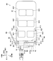
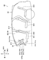
- FIG. 1 is a plan perspective view of a vehicle equipped with an air blowing device according to a first embodiment.
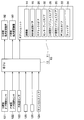
- 1 is a side perspective view of a vehicle equipped with an air blowing device according to a first embodiment. It is a control block diagram for explaining input and output of a signal to an air-conditioner control device in a 1st embodiment.
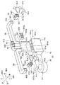
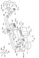
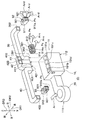
- FIG. 2 is an exploded perspective view showing the air conditioner unit and peripheral components of the air conditioner unit in the first embodiment, wherein air is blown out from a D-seat-side side face outlet while the D-seat-side door opening is being opened. It is a figure showing a state.
- FIG. 3 is a cross-sectional view schematically illustrating a part of a circulation path through which air flows in the air conditioner unit according to the first embodiment.
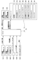
- FIG. 7 is a diagram showing an input / output system of signals transmitted and received by the air conditioner control device when step S161 is executed following step S101 in FIG. 6 in the first embodiment, corresponding to FIG. 3.
- FIG. 7 is a diagram showing an input / output system of signals transmitted and received by the air conditioner control device when step S161 is executed following step S101 in FIG. 6 according to the first embodiment, as indicated by arrows in FIG.
- FIG. 5 is an exploded perspective view showing the air conditioner unit and peripheral components of the air conditioner unit in the first embodiment in the same manner as FIG.
- FIG. 5 is a side perspective view of a vehicle equipped with an air blowing device according to a second embodiment, which is a diagram corresponding to FIG. 2.
- FIG. 10 is a control block diagram for explaining input and output of signals to and from an air conditioner control device in a third embodiment, and is a diagram corresponding to FIG. 3.
- FIG. 10 is a diagram illustrating a predetermined area around the vehicle in a plan perspective view of the vehicle corresponding to FIG. 1 in the third embodiment.
- FIG. 17B is a second flowchart following FIG.
- FIG. 16A of the third embodiment is a diagram corresponding to FIG. 6.
- 7 is a flowchart illustrating a control process executed by the air conditioner control device of the fourth embodiment in parallel with the control process of FIG. 6.
- FIG. 12 is a perspective view showing a P-seat-side door opening and the periphery thereof when the door is open, corresponding to FIG. 11, in the fifth embodiment.
- an exploded perspective view showing an air conditioner unit and peripheral parts of the air conditioner unit, and showing a state in which air is blown out from a D-seat-side outward air outlet while the D-seat-side door opening is being opened. It is a figure and is a figure corresponding to FIG. FIG.
- FIG. 9 is an exploded perspective view showing an air conditioner unit and peripheral components of the air conditioner unit in another embodiment, and showing a state in which air is blown out from a plurality of outlets during opening of a door at a D-seat side door opening.
- FIG. 5 is a diagram corresponding to FIG.
- FIG. 9 is an exploded perspective view showing an air conditioner unit and peripheral components of the air conditioner unit in another embodiment, and showing a state in which air is blown out from a plurality of outlets during opening of a door at a D-seat side door opening.
- FIG. 5 is a diagram corresponding to FIG. FIG.
- FIG. 9 is an exploded perspective view showing an air conditioner unit and peripheral components of the air conditioner unit in another embodiment, and showing a state in which air is blown out from a plurality of outlets during opening of a door at a D-seat side door opening.
- FIG. 5 is a diagram corresponding to FIG.
- an air blowing device 10 of the present embodiment includes an air conditioner unit 11 for performing air conditioning in a vehicle interior and an air conditioner control device 12 which is a control device for controlling the air conditioner unit 11.
- the air blowing device 10 is mounted on a vehicle 80.
- the vehicle 80 includes a plurality of door openings 82 and 84 provided in a vehicle body 81 constituting the vehicle 80, and a plurality of doors 86 and 88 that open and close the plurality of door openings 82 and 84. ing.
- the air blowing device 10 opens the door openings 82, 84. Blow out the air. As a result, the air blowing device 10 reduces entry of foreign matter such as mosquitoes 99 into the vehicle interior from the opened door openings 82 and 84.
- the vehicle 80 on which the air blowing device 10 is mounted may be a hybrid vehicle or an electric vehicle, but in the present embodiment, is an engine vehicle that includes only an engine as a driving source for traveling and travels with the engine. As shown in FIGS. 1 and 2, the vehicle 80 includes a plurality of front seats 901 and 902, a plurality of rear seats 903 arranged on the vehicle rear side of the front seats 901 and 902, and an instrument panel 91. In the vehicle interior. In other words, the vehicle interior is a vehicle interior space formed inside the vehicle body 81.
- the arrows DR1, DR2, and DR3 in FIGS. 1 and 2 indicate the direction of the vehicle 80. That is, the arrow DR1 in FIG. 1 indicates the front-back direction DR1 of the vehicle 80 (in other words, the vehicle front-back direction DR1), and the arrow DR2 indicates the left-right direction DR2 of the vehicle 80 (in other words, the vehicle left-right direction DR2).
- the arrow DR3 in FIG. 2 indicates the vertical direction DR3 of the vehicle 80 (in other words, the vehicle vertical direction DR3).
- These directions DR1, DR2, DR3 are directions that intersect each other, strictly speaking, directions that are orthogonal to each other. Further, the vehicle left-right direction DR2 may be referred to as a vehicle width direction DR2.
- the plurality of front seats 901, 902 and rear seats 903 are seats on which the occupant sits.
- the plurality of front seats 901 and 902 are all the seats 901, 902 and 903 that are arranged closest to the front of the vehicle.
- the plurality of front seats 901 and 902 include a driver seat 901 on which a driver, one of the occupants, sits, and a passenger seat 902.
- the driver's seat 901 is arranged on one side with respect to the center position in the vehicle compartment in the vehicle lateral direction DR2, and the passenger seat 902 is arranged on the other side with respect to the center position in the vehicle compartment. That is, the driver's seat 901 is arranged on one side of the passenger seat 902 in the vehicle left-right direction DR2.
- the vehicle 80 of this embodiment is a right-hand drive vehicle.
- one side in the vehicle left-right direction DR2 is the vehicle right side
- the other side in the vehicle left-right direction DR2 is the vehicle left side.
- the driver's seat 901 is abbreviated as a D seat 901
- the passenger seat 902 is abbreviated as a P seat 902.
- the plurality of door openings 82 and 84 of the vehicle 80 are formed between the A pillar 811 and the B pillar 812 in the vehicle longitudinal direction DR1.
- the A pillar 811 and the B pillar 812 are pillars constituting a part of the vehicle body 81, respectively.
- the A pillar 811 is arranged closest to the front of the vehicle among the plurality of pillars forming the vehicle body 81, and the B pillar 812 is arranged at a position next to the A pillar 811 counted from the front of the vehicle.
- the plurality of door openings 82 and 84 include a D-seat-side door opening 82 corresponding to the driver's seat 901 and a P-seat-side door opening 84 corresponding to the passenger seat 902.
- the D-seat-side door opening 82 is provided on the right side of the vehicle body 81 and opens toward the right side of the vehicle. That is, the D-seat-side door opening 82 is disposed on the right side of the vehicle with respect to the driver's seat 901.
- the P-seat-side door opening 84 is provided on the left side of the vehicle body 81 and opens to the left of the vehicle. That is, the P-seat side door opening 84 is disposed on the left side of the vehicle with respect to the passenger seat 902.
- the plurality of doors 86 and 88 included in the vehicle 80 include a D-seat side door 86 and a P-seat side door 88.
- the D seat side door 86 is attached to the right side of the vehicle body 81 and opens and closes the D seat side door opening 82.
- the P-seat side door 88 is attached to the left side of the vehicle body 81 and opens and closes the P-seat side door opening 84.
- the D-seat-side door 86 opens and closes the D-seat-side door opening 82 by rotating as shown by the arrow Ad. That is, the D-seat-side door 86 is rotated around the vehicle front-side end of the D-seat side door 86 so that the rear end of the vehicle is separated from the vehicle body 81 to the outside of the vehicle compartment, The D seat side door opening 82 is opened. The D-seat-side door 86 closes the D-seat-side door opening 82 by pivoting around the front end of the vehicle such that the rear end of the vehicle approaches the vehicle body 81.
- the operation of the P-seat side door 88 to open and close the P-seat side door opening 84 is the same as this. That is, the P-seat-side door 88 opens and closes the P-seat-side door opening 84 by rotating as shown by the arrow Ap.
- the instrument panel 91 is arranged on the front side of the vehicle in the vehicle interior. Specifically, the instrument panel 91 is disposed on the front side of the front seats 901 and 902 in the vehicle longitudinal direction DR1. Further, the instrument panel 91 is arranged closer to the vehicle front side than the door openings 82 and 84. Further, the instrument panel 91 is provided over the entire width or substantially the entire width of the vehicle cabin in the vehicle left-right direction DR2.
- the air conditioner unit 11 is arranged inside the instrument panel 91.
- the air conditioner unit 11 performs air conditioning of the vehicle interior by blowing air-conditioned air whose temperature has been adjusted in the air conditioner unit 11 into the vehicle interior.
- the air conditioner unit 11 is roughly composed of a blower unit 111 and a temperature adjustment unit 112.
- the temperature adjustment unit 112 is arranged at the center of the vehicle lateral direction DR2 inside the instrument panel 91 in the vehicle interior, and the blower unit 111 is arranged on the left side of the vehicle with respect to the temperature adjustment unit 112.
- the blower unit 111 of the air conditioner unit 11 has a blower 14, an inside / outside air switching door 16, and a blower unit case 18.
- the blower 14 sucks air from inside or outside the vehicle, and blows the sucked air to the temperature control unit 112.
- the air inside the vehicle compartment is called inside air
- the air outside the vehicle compartment is called outside air.
- the inside / outside air switching door 16 is a switching device that switches the air taken in by the blower 14 between inside air and outside air. Therefore, the air conditioner unit 11 is configured to be switchable to each of a plurality of suction modes including the outside air mode.
- the plurality of suction modes include an inside air mode in addition to the outside air mode.
- the suction mode of the air conditioner unit 11 of the present embodiment can be switched between the inside air mode and the outside air mode by operating the inside / outside air switching door 16.
- the blower 14 In the inside air mode, the blower 14 is prevented from sucking outside air by the inside / outside air switching door 16 while the inside air is exclusively guided to the blower 14, and the blower 14 sucks inside air.
- the blower 14 Conversely, in the outside air mode, the blower 14 sucks inside air by the inside / outside air switching door 16 while the outside air is exclusively guided to the blower 14, and the blower 14 sucks outside air.
- the arrow Ari in FIG. 4 indicates the flow of the outside air sucked into the blower 14 in the outside air mode.
- the blower unit case 18 forms the outer shell of the blower unit 111 and houses the impeller of the blower 14 and the inside / outside air switching door 16. Further, inside the blower unit case 18, an air guide path for guiding the air blown from the blower 14 to the temperature adjustment unit 112 is formed.
- the temperature adjustment unit 112 of the air conditioner unit 11 includes a temperature adjustment unit case 19, an evaporator 22, a heater core 24, an air mix door 26, a D-seat side face door 28, and a P-seat side side. It has a face door 30 and a center face door 32.
- the temperature adjustment unit case 19 forms an outer shell of the temperature adjustment unit 112.
- the blower unit case 18 and the temperature adjustment unit case 19 are integrally formed to form an air conditioning case 20 which forms an outer shell of the air conditioner unit 11.
- an air-conditioning ventilation passage 19 a through which air blown from the blower 14 flows is formed inside the temperature adjustment unit case 19. That is, the air-conditioning ventilation passage 19 a is an air passage formed inside the air-conditioning unit 11. Since FIG. 5 is a schematic diagram, the air circulation path is simplified in FIG.
- the evaporator 22, the heater core 24, and the air mix door 26 are provided in the air-conditioning ventilation passage 19a. That is, the evaporator 22, the heater core 24, and the air mix door 26 are housed in the temperature adjustment case 19.
- the evaporator 22 is arranged at the most upstream side of the air flow in the air conditioning ventilation passage 19a. Therefore, the air blown out from the blower 14 flows into the air-conditioning ventilation path 19a, but the air from the blower 14 first flows into the evaporator 22 in the air-conditioning ventilation path 19a.
- the evaporator 22 is a cooling heat exchanger that cools the air flowing through the air-conditioning ventilation passage 19a.
- the evaporator 22 evaporates the refrigerant and cools the air by exchanging heat between the air and the refrigerant.
- the heater core 24 is disposed downstream of the air flow with respect to the evaporator 22 in the air-conditioning ventilation passage 19a.
- the heater core 24 is a heating heat exchanger that heats the air flowing out of the evaporator 22 in the air-conditioning ventilation passage 19a.
- the heater core 24 heats the air with the heat of the engine cooling water by exchanging heat between the air and the engine cooling water.
- the air-conditioning ventilation path 19a has a hot-air path 19b that allows air to flow through the heater core 24 and a bypass path 19c that allows air to bypass the heater core 24 and flow air downstream of the air flow to the evaporator 22.
- the hot air passage 19b is a first air passage for passing the air flowing from the blower 14 to the heater core 24.
- the bypass passage 19c is a second air passage that is provided in parallel with the hot air passage 19b and that allows the air flowing from the blower 14 to bypass the heater core 24.
- the air mix door 26 is a passage opening and closing device that opens and closes the hot air passage 19b and opens and closes the bypass passage 19c.
- the air mix door 26 is configured as a pivoting door that pivots, for example, as indicated by an arrow Dam.
- the air mix door 26 can continuously increase and decrease the opening of the hot air passage 19b and the opening of the bypass passage 19c.
- the air mix door 26 adjusts the ratio of the flow rate of the warm air passage 19b to the flow rate of the bypass passage 19c by changing the opening degree thereof.
- the air mix door 26 adjusts the temperature of the conditioned air flowing out of the air conditioner unit 11 by adjusting the air volume ratio.
- the door position where the air mix door 26 minimizes the opening of the hot air passage 19b and maximizes the opening of the bypass passage 19c (for example, 100%) is referred to as a MAXCOOL position.
- the hot air passage 19b is closed.
- the air mix door 26 is shown in the MAXCOOL position.
- the door position where the air mix door 26 maximizes the opening of the hot air passage 19b (for example, 100%) and minimizes the opening of the bypass passage 19c is referred to as a MAXHOT position.
- the bypass passage 19c is closed.
- the temperature adjustment unit case 19 includes a plurality of outlet openings 191 a, 191 b, 191 c, and 191 d communicating with the air-conditioning ventilation passage 19 a on the downstream side of the air flow with respect to each of the hot air passage 19 b and the bypass passage 19 c. have.
- the conditioned air whose temperature has been adjusted by the air mix door 26 is blown out from any or all of the plurality of blowout openings 191a, 191b, 191c, and 191d.
- the blowout openings 191a, 191b, 191c, and 191d are also abbreviated as blowout openings 191a to 191d.
- the plurality of outlet openings 191a to 191d of the temperature adjustment unit case 19 include, for example, a D-seat side face outlet 191a, a P-seat side face outlet 191b, and two center face outlets 191c. 191d.
- the center face blowout openings 191c and 191d blow out the conditioned air toward the upper body of the occupant sitting on the front seats 901 and 902 at the center position in the vehicle compartment in the vehicle lateral direction DR2.
- the D-seat-side side face blowing opening 191a blows out conditioned air toward the upper body of the occupant sitting on the driver's seat 901 at a position deviated to the driver's seat 901 to the right of the vehicle.
- the P-seat-side side face blowing opening 191b blows out conditioned air toward the upper body of the occupant sitting on the passenger seat 902 at a position deviated to the left of the vehicle with respect to the passenger seat 902.
- the temperature adjustment unit case 19 also has a defroster blowout opening and a foot blowout opening (not shown) as blowout openings.
- the defroster blowing opening blows out conditioned air toward the front window of the vehicle.
- the foot blowout opening blows out the conditioned air toward the feet of the occupant in the passenger compartment.
- a D-seat-side side face door 28 is provided in the D-seat-side side face blowing opening 191a.
- the D-seat side face door 28 opens and closes the D-seat side face blow-out opening 191a.
- the P-seat side face door 30 is provided in the P-seat side face face opening 191b.
- the P-seat side face door 30 opens and closes the P-seat side face blow-out opening 191b.
- a center face door 32 is provided in each of the two center face blowing openings 191c and 191d.
- the center face door 32 opens and closes the two center face outlet openings 191c and 191d.
- the defroster outlet opening is provided with a defroster door 33 for opening and closing the defroster outlet opening, and the foot outlet opening is provided with a foot door 34 for opening and closing the foot outlet opening.
- Air conditioning ducts 39, 40, 41, and 42 are connected to the plurality of outlets 191a to 191d of the temperature adjustment unit case 19, respectively.
- the conditioned air flowing out of the outlets 191a to 191d passes through air conditioning ducts 39, 40, 41, and 42, and is blown into the vehicle interior.
- the vehicle 80 includes a plurality of air conditioning ducts 39, 40, 41, 42 connected to the air conditioner unit 11 according to the number of the air outlets 191 a to 191 d of the air conditioner unit 11.
- the air-conditioning air flowing out of the air-conditioning unit 11 when the air-conditioning unit 11 air-conditions the passenger compartment flows through the air-conditioning ducts 39, 40, 41, and 42, respectively.
- the air conditioning ducts 39, 40, 41, and 42 are also abbreviated as air conditioning ducts 39 to 42.
- a plurality of air conditioning ducts 39 to 42 of the vehicle 80 include, for example, a D-seat side face duct 39, a P-seat side face duct 40, and two center face ducts 41 and 42. Is included.
- the vehicle 80 is connected as an air conditioning duct to the defroster duct connected to the above-described defroster outlet opening and to the foot outlet opening. It also has a foot duct.
- the inlet end 391 which is the airflow upstream end of the D-seat side face duct 39 is connected to the D-seat side face blow-out opening 191a.
- the D-seat-side side face outlet 911a is formed in the D-seat-side outlet 911 of the instrument panel 91.
- the D-seat-side side face outlet 911a opens into the vehicle cabin at a position on the instrument panel 91 near the right end of the vehicle. Therefore, when the air conditioner unit 11 performs air conditioning in the vehicle interior, the airflow of the conditioned air flowing out of the D-seat-side side face outlet 191a and passing through the D-seat-side side face duct 39 is established. Into the cabin.
- the inlet end 401 which is the airflow upstream end of the P seat side face duct 40, is connected to the P seat side face outlet 191b.
- the outlet end 402 which is the airflow downstream end of the P-seat side face duct 40, is connected to the P-seat side face outlet 912a.
- the P-seat-side side face outlet 912a is formed in the P-seat-side outlet 912 of the instrument panel 91.
- the P-seat-side side face outlet 912a opens into the vehicle cabin at a position on the instrument panel 91 near the left end of the vehicle. Therefore, when the air conditioner unit 11 performs air conditioning in the passenger compartment, the P-seat side face face outlet 912a flows out of the P-seat side face face opening 191b and passes through the P-seat side face face duct 40. Into the cabin.
- the two center face outlets 913a and 914a are formed in two center outlets 913 and 914 of the instrument panel 91, respectively.
- the center face outlets 913a and 914a open into the vehicle cabin at the position of the center of the instrument panel 91 in the vehicle left-right direction DR2.
- the position of the central portion in the vehicle lateral direction DR2 is, for example, a central position between the installation position of the D seat side door 86 and the installation position of the P seat side door 88 in the vehicle lateral direction DR2.
- One of the two center face outlets 913a blows out the conditioned air flowing out of the center face outlet 191c and passing through the center face duct 41 into the passenger compartment when the air conditioner unit 11 performs air conditioning in the passenger compartment. .
- the other of the two center face outlets 914a is supplied with the conditioned air flowing out of the center face outlet 191d and passing through the center face duct 42.
- the air conditioner unit 11 is configured to allow air from the air conditioner unit 11 to flow to the center face outlets 913a and 914a which are located at the center of the vehicle 80 in the vehicle lateral direction DR2 and open to the vehicle interior. Is provided.
- the face outlets 911a, 912a, 913a, and 914a are air-conditioning outlets that are provided in the vehicle compartment and blow out conditioned air when the air conditioner unit 11 performs air conditioning in the vehicle compartment.
- the face outlets 911a, 912a, 913a, and 914a are also abbreviated as face outlets 911a to 914a.
- the vehicle cabin has an air-conditioning air outlet which is connected to a defroster air outlet through a defroster air duct and a foot air outlet through a foot duct.
- a connected foot outlet is provided.
- the vehicle 80 also has a D-seat-side wind direction changing device 92 provided in the D-seat-side blowing section 911, and a P-seat-side wind direction changing device 93 provided in the P-seat-side blowing section 912.
- the D-seat side wind direction changing device 92 changes the blowing direction of the air blown out from the D-seat side face outlet 911a.
- the D-seat-side wind direction changing device 92 has a louver and an actuator 921 provided in the D-seat-side side face outlet 911a. The blowing direction of 911a is changed.
- the P-seat side wind direction changing device 93 changes the blowing direction of the air blown out from the P-seat side face outlet 912a.
- the P-seat side wind direction changing device 93 has a louver and an actuator 931 provided in the P-seat side face outlet 912a, and the P-seat side face outlet is changed by changing the direction of the louver with the actuator 931. The blowing direction of 912a is changed.
- louver of the D-seat-side wind direction changing device 92 is configured so that the direction of the louver can be manually changed freely when the D-seat-side wind direction changing device 92 is not energized to the actuator 921. The same applies to the louver of the P-seat side wind direction changing device 93.
- the air conditioner control device 12 shown in FIG. 3 is configured by a microcomputer including a CPU, a ROM, a RAM, and the like (not shown).
- a signal from a sensor or the like connected to the air conditioner control device 12 is configured to be input to the air conditioner control device 12 after being A / D converted by an input circuit (not shown).
- the signal lines connecting the air conditioner control device 12 and a plurality of connected devices such as sensors electrically connected to the air conditioner control device 12 may be respectively connected in parallel from the air conditioner control device 12 to each connected device. Alternatively, they may be connected in series. When the signal lines are connected in series, the LIN protocol or the like is used.
- a plurality of input-side connection devices 121 to 126 are electrically connected to the air conditioner control device 12.
- the plurality of input-side connected devices 121 to 126 are, for example, a D-seat-side door open / close sensor 121, a P-seat-side door open / close sensor 122, an outside air temperature sensor 123, a cancel switch 124, an ignition switch 125, and a battery voltage sensor 126.
- the signals from the input side connection devices 121 to 126 may be input to the air conditioner control device 12 via a control device other than the air conditioner control device 12, or the other control devices may be used.
- the information may be directly input to the air conditioner control device 12 without passing through.
- the D-seat-side door open / close sensor 121 detects whether the D-seat-side door 86 has opened the D-seat-side door opening 82. In short, the D-seat-side door open / close sensor 121 detects whether the D-seat side door 86 is open or closed. A detection signal indicating the open / closed state of the D-seat-side door 86 is input to the air-conditioner control device 12 from the D-seat-side door open / close sensor 121. Therefore, the air conditioner control device 12 recognizes that the D-seat-side door 86 has opened the D-seat-side door opening 82 based on the detection signal from the D-seat-side door open / close sensor 121.
- the P-seat-side door opening / closing sensor 122 detects whether the P-seat-side door 88 has opened the P-seat-side door opening 84. In short, the P-seat-side door open / close sensor 122 detects whether the P-seat side door 88 is open or closed. A detection signal indicating the open / close state of the P seat side door 88 is input to the air conditioner control device 12 from the P seat side door open / close sensor 122. Therefore, the air conditioner control device 12 recognizes that the P-seat-side door 88 has opened the P-seat-side door opening 84 based on the detection signal from the P-seat-side door open / close sensor 122.
- the outside air temperature sensor 123 detects the outside air temperature Tam, which is the temperature of the outside air around the vehicle 80. A detection signal indicating the outside air temperature Tam is input from the outside air temperature sensor 123 to the air conditioner control device 12.
- the cancel switch 124 is an occupant operation switch operated by the occupant, and is provided at a location in the vehicle compartment, such as on the instrument panel 91, where the occupant can easily operate. Specifically, the cancel switch 124 is a switch for switching between permission and non-permission for executing the control process of FIG. 6 described later. In other words, the cancel switch 124 is a switch that switches between permission and non-permission for blowing air from the predetermined outlet Ps while the door 86 or 88 is open with any of the door openings 82 and 84 open. is there. Note that the side face outlets 911a and 912a correspond to the predetermined outlet Ps mentioned here.
- the ignition switch 125 is a vehicle activation switch that switches on and off the occupant in order to make the vehicle 80 operable. Therefore, when the ignition switch 125 is turned off, the vehicle 80 is in a state where it cannot travel. Conversely, when the ignition switch 125 is turned on, the vehicle 80 is ready to run. For example, when the accelerator pedal is depressed after the ignition switch 125 is turned on, the vehicle 80 starts.
- the vehicle 80 of the present embodiment is an engine vehicle as described above, if the vehicle 80 is a hybrid vehicle or an electric vehicle, the ignition switch 125 is called, for example, a vehicle start switch.
- a signal indicating ON / OFF of the ignition switch 125 is input from the ignition switch 125 to the air conditioner control device 12.
- the ignition switch 125 may be, for example, an insertion key inserted into a keyhole or a push button.
- the power of a predetermined on-board device such as an audio device mounted on the vehicle 80 is also turned off.
- the battery voltage sensor 126 detects a voltage Vb (in other words, a power supply voltage Vb) of a battery that is a power supply of the vehicle 80.
- a detection signal indicating the battery voltage Vb is input from the battery voltage sensor 126 to the air conditioner control device 12.
- the D-seat-side wind direction changing device 92, the P-seat-side wind direction changing device 93, the air conditioner unit 11, and the like are electrically connected to the air conditioner control device 12 as output-side connection devices.
- the air conditioner control device 12 outputs a control signal for controlling the operation of each of the D seat side wind direction changing device 92, the P seat side wind direction changing device 93, and the air conditioner unit 11.
- the control signal for the air conditioner unit 11 is, specifically, a control signal for controlling the operation of each component of the air conditioner unit 11 such as the blower 14.
- the air conditioner control device 12 executes a computer program stored in a semiconductor memory such as a ROM or a RAM which is a non-transitional substantial storage medium.
- a method corresponding to the computer program is executed. That is, the air conditioner control device 12 executes various control processes such as the control process of FIG. 6 according to the computer program.
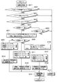
- FIG. 6 is a flowchart showing a control process executed by the air conditioner control device 12 of the present embodiment.
- the air conditioner control device 12 since the cancel switch 124 is provided, the air conditioner control device 12 performs the control process of FIG. 6 only when the execution of the control process of FIG. Execute The control process of FIG. 6 is periodically and repeatedly executed.
- step S011 the air conditioner control device 12 acquires signals from the outside air temperature sensor 123, the ignition switch 125, and the battery voltage sensor 126.
- the air conditioner control device 12 recognizes the outside air temperature Tam, the on / off state of the ignition switch 125, and the battery voltage Vb.
- step S021 the process proceeds to step S021.
- step S021 the air conditioner control device 12 determines whether or not the outside air temperature Tam is equal to or higher than a predetermined lower limit of outside air temperature T1am and equal to or lower than a predetermined upper limit of outside air temperature T2am.
- the outside air temperature upper limit T2am is a temperature higher than the outside air temperature lower limit T1am.
- the outside temperature lower limit T1am and the outside temperature upper limit T2am are experimentally determined in advance so that the temperature range from the outside temperature lower limit T1am to the outside temperature upper limit T2am matches the temperature range in which mosquitoes fly. This is because the control processing of FIG. 6 is executed to prevent foreign substances such as mosquitoes from entering the vehicle interior.
- step S021 If it is determined in step S021 that the outside air temperature Tam is equal to or higher than the outside air temperature lower limit T1am and equal to or lower than the predetermined outside air temperature upper limit T2am, the process proceeds to step S031. On the other hand, if it is determined that the outside air temperature Tam is lower than the outside air temperature lower limit T1am, or if it is determined that the outside air temperature Tam is higher than the outside air temperature upper limit T2am, the process proceeds to step S171.
- step S031 the air conditioner control device 12 determines whether the battery voltage Vb is equal to or higher than a predetermined voltage determination value V1b.
- the voltage determination value V1b is experimentally determined in advance so that if the battery voltage Vb is lower than the voltage determination value V1b, it can be determined that the battery is undercharged.
- step S031 If it is determined in step S031 that the battery voltage Vb is equal to or higher than the voltage determination value V1b, the process proceeds to step S041. On the other hand, when it is determined that the battery voltage Vb is lower than the voltage determination value V1b, the process proceeds to step S171.
- step S041 the air conditioner control device 12 determines whether or not the ignition switch 125 is off (ie, OFF).
- step S041 If it is determined in step S041 that the ignition switch 125 is off, the process proceeds to step S051. On the other hand, when it is determined that the ignition switch 125 is not off, the process proceeds to step S171.
- the case where the ignition switch 125 is not off is assumed to be the case where the ignition switch 125 is on or the case where the ignition switch 125 is switched to another switch state which is neither on nor off.
- step S051 the air conditioner control device 12 acquires a signal from the D-seat-side door opening / closing sensor 121. Thereby, the air conditioner control device 12 recognizes the open / closed state of the D-seat side door 86 shown in FIG.
- the air conditioner control device 12 determines whether or not the D-seat side door 86 is opening the D-seat side door opening 82.
- step S051 If it is determined in step S051 that the D-seat-side door opening 82 is opening the door, the flow proceeds to step S071. On the other hand, if it is determined that the D-seat-side door opening 82 is not opening the door, the process proceeds to step S061. Specifically, the case where the D-seat-side door opening 82 is not open is the case where the D-seat-side door 86 is closing the D-seat-side door opening 82 with the D-seat-side door 86. .
- step S061 the air conditioner control device 12 acquires a signal from the P-seat-side door open / close sensor 122. Thereby, the air conditioner control device 12 recognizes the open / closed state of the P seat side door 88 shown in FIG.
- the air conditioner control device 12 determines whether or not the P-seat-side door opening 88 is being opened by the P-seat-side door 88.
- step S061 If it is determined in step S061 that the P-seat-side door opening 84 is open, the process proceeds to step S131. On the other hand, when it is determined that the P-seat-side door opening 84 is not opening the door, the process proceeds to step S171. Specifically, the case where the P-seat-side door opening 84 is not being opened is a case where the P-seat-side door 88 is closing the P-seat-side door opening 84 with the P-seat-side door 88. .
- step S071 the air conditioner control device 12 prevents the air conditioner unit 11 from invading foreign matter such as mosquitoes from the door openings 82 and 84 while the door is open.
- the air conditioner unit 11 is continued in the intrusion prevention mode.
- the suction mode of the air conditioner unit 11 is set to the outside air mode.
- the door position of the air mix door 26 is set to the MAXCOOL position.
- the air blowing mode of the air conditioner unit 11 is a face mode.
- the face mode is a mode in which air is exclusively blown out from the face blowing openings 191a, 191b, 191c, and 191d, and the opening and closing of the face doors 28, 30, and 32 follow steps S091, S111, and S141 described later. Therefore, in step S071, the air conditioner control device 12 does not operate the face doors 28, 30, and 32, and closes the defroster door 33 and the foot door 34. After step S071, the process proceeds to step S081.
- step S081 the air conditioner control device 12 performs the same processing as in step S061 described above. That is, the air conditioner control device 12 recognizes the open / closed state of the P seat side door 88 shown in FIG. 1 based on the signal from the P seat side door open / close sensor 122. Then, the air conditioner control device 12 determines whether or not the P-seat-side door opening 84 is opening the door.
- step S081 If it is determined in step S081 that the P-seat-side door opening 84 is being opened, the process proceeds to step S111. On the other hand, when it is determined that the P-seat-side door opening 84 is not opening the door, the process proceeds to step S091.
- step S091 the air conditioner control device 12 sets the face blowout openings 191a, 191b, 191c, and 191d to the D seat side open state. If the face blowing openings 191a, 191b, 191c, and 191d are already in the D-seat side open state, the operation is continued in the D-seat side open state.
- step S091 the process proceeds to step S101.
- FIG. 4 shows the D-side open state of the face blowout openings 191a, 191b, 191c, and 191d.
- the point hatching provided on the P-seat side side face opening 191b and the center face opening 191c, 191d is such that the opening 191b, 191c, 191d is closed. It is shown that.
- the fact that the hatching indicates that the blowout opening is closed is the same in the following drawings similar to FIG. 4.
- step S101 in FIG. 6 the air conditioner control device 12 sets the D-seat side wind direction changing device 92 to direct the blowout direction of the D-seat side face face outlet 911a to the outside of the cabin through the D-seat side door opening 82.
- the D-seat-side side face outlet 911 a allows air to flow from the interior of the vehicle to the exterior of the D-seat-side door opening 82 via the D-seat-side door opening 82. Outlet.
- the D-seat-side side face outlet 911a is an outlet that blows air from the vehicle interior side to the D-seat side door opening 82 so as to pass through the D-seat side door opening 82 to the outside of the vehicle.
- the blowout direction of the D-seat-side side face blowout port 911a in the outward blowout mode is a direction facing the rear side of the vehicle and the diagonally right side of the vehicle, and the blowout direction is experimentally determined in advance. Stipulated. After step S101, the process proceeds to step S161.
- step S161 since the blower 14 is operated in step S161 described later, if step S161 is executed following step S101, the D-side seat side face blower is exclusively used as shown by the arrow Ard in FIGS. Air is blown out from the outlet 911a.
- the D-seat-side side face outlet 911a and the P-seat-side side face outlet 912a correspond to the predetermined outlet Ps. That is, in the present embodiment, two predetermined outlets Ps are provided.
- step S101 the air conditioner control device 12 controls the D-seat-side wind direction changing device 92 when blowing air from the predetermined outlet Ps while the door of the D-seat-side door opening 82 is open. It can be said that the blowing direction of the predetermined outlet Ps is directed to the outside of the vehicle compartment.
- step S161 The signals transmitted and received by the air conditioner control device 12 when step S161 is executed following step S101 are exemplified in FIGS. 7 and 8.
- “I / G” shown in FIG. 8 is an abbreviation for an ignition switch.
- step S111 the air conditioner control device 12 sets the face blowout openings 191a, 191b, 191c, and 191d to the open state on both sides. If the face blowing openings 191a, 191b, 191c, and 191d are already open on both sides, the operation is continued in the open state on both sides.
- step S111 the process proceeds to step S121.
- FIG. 9 shows a state in which both sides of the face blowing openings 191a, 191b, 191c, and 191d are open. Specifically, in FIG. 9, dot hatching given to the center face blowout openings 191c and 191d indicates that the center face blowout openings 191c and 191d are closed.
- step S121 in FIG. 6 the air conditioner control device 12 sets the D-seat side wind direction changing device 92 to the outward air outlet mode as in step S101 described above.
- the air conditioner control device 12 also sets the P-seat side wind direction changing device 93 to the predetermined outward air outlet mode.
- the P-seat side air direction changing device 93 adjusts the blowing direction of the P-seat side side face outlet 912a to the outside of the vehicle cabin through the P-seat side door opening 84.
- the P-seat-side side face outlet 912 a allows air to flow from the inside of the cabin to the outside of the cabin with respect to the P-seat side door opening 84 via the P-seat side door opening 84. Outlet.
- the P-seat-side side face outlet 912a is an outlet that blows air from the inside of the vehicle with respect to the P-seat-side door opening 84 to the outside of the cabin through the P-seat-side door opening 84.
- the blowout direction of the P-seat side face blowout port 912a in the outward blowout mode is a direction facing the rear side of the vehicle and the diagonally left side of the vehicle, and the blowout direction is experimentally determined in advance.
- step S161 the blower 14 is operated. Therefore, when step S161 is executed following step S121, air is exclusively blown out from the D- and P-seat side face outlets 911a and 912a as indicated by arrows Ard and Arp in FIG. .
- the D-seat-side side face outlet 911a and the P-seat-side side face outlet 912a correspond to the predetermined outlet Ps.
- the air conditioner control device 12 performs the following in step S121. That is, when air is blown out from the predetermined air outlet Ps while the doors of the D-seat side and P-seat side door openings 82 and 84 are open, the air conditioner control device 12 sets the D-seat-side and P-seat-side wind direction change devices 92. , 93 can be said to direct the blowing direction of the predetermined outlet Ps toward the outside of the vehicle compartment.
- step S131 the air conditioner control device 12 performs the same processing as in step S071 described above. That is, the air conditioner control device 12 sets the air conditioner unit 11 to the intrusion prevention mode. If the air conditioner unit 11 is already in the intrusion prevention mode, the air conditioner unit 11 is continued in the intrusion prevention mode. After step S131, the process proceeds to step S141.
- step S141 the air conditioner control device 12 sets the face outlet openings 191a, 191b, 191c, 191d to the P seat side open state. If the face blowing openings 191a, 191b, 191c, and 191d are already in the P-seat side open state, the P-seat side open state is continued.
- the P-seat-side side face opening 191b is opened by the P-seat-side side face door 30.
- the D-seat side face face opening 191a is closed by the D-seat side face door 28, and the center face blowing openings 191c and 191d are closed by the center face door 32. Therefore, after the completion of the process in step S141, all the blowout openings except the P-seat side face blowout opening 191b are closed. After step S141, the process proceeds to step S151.
- step S151 the air conditioner control device 12 sets the P-seat side wind direction changing device 93 to the outward air outlet mode as in step S121 described above. However, unlike step S121, the air conditioner control device 12 does not operate the D-seat-side wind direction changing device 92. After step S151, the process proceeds to step S161.
- step S161 the blower 14 is operated. Therefore, when step S161 is executed following step S151, air is exclusively blown from the P-seat-side side face outlet 912a as indicated by an arrow Arp in FIG.
- the D-seat-side side face outlet 911a and the P-seat-side side face outlet 912a correspond to the predetermined outlet Ps.
- the air conditioner control device 12 performs the following in step S151. That is, the air conditioner control device 12 controls the P-seat-side wind direction changing device 93 to blow air from the predetermined outlet Ps while the door of the P-seat-side door opening 84 is open, thereby controlling the predetermined outlet. It can be said that the blowing direction of Ps is directed to the outside of the passenger compartment.
- step S161 the air conditioner control device 12 activates the blower 14 and causes the blower 14 to blow air.
- the air conditioner control device 12 operates the blower 14 to blow at the maximum air volume. If the blower 14 is already operating, the operation is continued.
- step S171 the air conditioner control device 12 stops the blower 14 which has been activated in step S161. If the blower 14 is already stopped, it is continued. Note that the processing in step S171 does not stop the blower 14 when the blower 14 is operating in a control process other than the control process in FIG. After steps S161 and S171, the process returns to step S011.
- the air conditioner control device 12 performs the control processing of FIG. 6 as described above. As a result, the air conditioner control device 12 operates the blower 14 while the door of the D-seat side door opening 82 is open as shown in FIG. Through the D-seat side face outlet 911a.
- the air conditioner control device 12 activates the blower 14 while the door of the P-seat side door opening 84 is open, and sends the air flowing from the blower 14 to the P-seat side face duct 40. And blows out from the P-seat side face outlet 912a.
- the occupant tries to get on from the D-seat side door opening 82
- the occupant opens the D-seat side door 86 as shown in FIG.
- the blower 14 sucks in the outside air as indicated by the arrow Ari in FIG.
- the sucked air (specifically, outside air) passes through the evaporator 22 and the bypass passage 19c of FIG. 5 in order from the blower 14 and flows out of the D-side seat side face opening 191a of FIG.
- step S161 is not executed according to the determination in step S141 in FIG. 6, so that the air conditioner unit 11 can return to normal air conditioning in the vehicle compartment.
- the air conditioner control device 12 executes the control process shown in FIG. Thereby, while the door of the D-seat side door opening 82 in FIG. 1 is open, the air conditioner control device 12 activates the blower 14, and the air flowing from the blower 14 passes through the D-seat side side face duct 39 to the predetermined position. The air is blown out from the D-seat-side side face air outlet 911a as the air outlet Ps. At this time, the D-seat-side side face outlet 911a blows air through the D-seat-side door opening 82 from the cabin side to the D-seat-side door opening 82 when the door is open.
- the air conditioner control device 12 activates the blower 14 and sends the air flowing from the blower 14 to the predetermined outlet Ps through the P-seat side face duct 40. From the P-seat side face outlet 912a. At this time, the P-seat side face outlet 912a blows air through the P-seat side door opening 84 from the inside of the vehicle to the P-seat side door opening 84 when the door is open.
- the D-seat-side side face outlet 911a as the predetermined outlet Ps is used when the air conditioner unit 11 performs air conditioning in the vehicle interior.
- the conditioned air that has passed through the seat-side side face duct 39 is blown out.
- the P-seat-side side face outlet 912a serving as the predetermined outlet Ps blows out conditioned air that has passed through the P-seat side face duct 40 when the air conditioner unit 11 performs air conditioning of the vehicle interior.
- the predetermined outlet Ps is not a dedicated outlet for blowing out air for the purpose of suppressing intrusion of foreign matter into the vehicle interior. That is, the air conditioning side face outlets 911a and 912a used for air conditioning in the vehicle cabin can be used as the predetermined outlet Ps. Therefore, it is possible to improve the mountability of the air blowing device 10 on the vehicle 80. Further, since the number of components can be reduced as compared with the case where a dedicated air outlet is provided as the predetermined air outlet Ps, the cost of the air blowing device 10 can be reduced.
- the air conditioner control device 12 performs a process of blowing air from the predetermined outlet Ps while one or both of the door openings 82 and 84 are open. Do the following: That is, the air conditioner control device 12 controls the one or both of the D-seat-side and P-seat-side wind direction change devices 92 and 93 to blow out the air in such a manner, thereby changing the blowout direction of the predetermined blowout port Ps. Turn to the outside of the cabin.
- the blowing directions of the air-conditioning side face air outlets 911a and 912a used as the predetermined air outlet Ps. Can be oriented appropriately.
- the air conditioner control device 12 performs a process of blowing air from the predetermined outlet Ps while one or both of the door openings 82 and 84 are open. , The air mix door 26 opens the bypass passage 19c. Specifically, the air conditioner control device 12 sets the door position of the air mix door 26 to the MAXCOOL position.
- the air conditioner control device 12 controls the air conditioner 12 to blow air from the predetermined outlet Ps while one or both of the door openings 82 and 84 are open.
- the air conditioner unit 11 is set to the outside air mode. Therefore, it is possible to prevent the air blown out from the predetermined outlet Ps from being drawn into the vehicle interior by the blower 14. As a result, for example, compared with the case where the air conditioner unit 11 is in the inside air mode, it is possible to improve the performance of preventing foreign substances from entering the vehicle interior from the door openings 82 and 84 while the door is open.
- the air in the vehicle compartment is forcibly ventilated by blowing out the outside air from the predetermined air outlet Ps. Therefore, for example, when it is assumed that an occupant gets on a car after parking for a long time under the scorching sun, it is possible to quickly ventilate the hot air in the passenger compartment when the occupant gets on the board, and to quickly cool down after the occupant and reduce the air conditioning load. Has the effect.
- the center face outlets 913a and 914a are different from the predetermined outlet Ps.
- the air conditioner control device 12 transmits air from the center face air outlets 913a and 914a to the vehicle interior. Stop blowing. Therefore, in response to stopping the air flow to the center face outlets 913a and 914a, which are some distance from the door openings 82 and 84, it is possible to secure a large amount of air blown out from the predetermined outlet Ps. It is possible.
- the flowchart of FIG. 6 includes step S021 for determining the outside air temperature Tam. That is, the air conditioner control device 12 opens one or both of the door openings 82 and 84 on the condition that the outside air temperature Tam is equal to or higher than the predetermined lower limit value T1am and equal to or lower than the predetermined upper limit value T2am. The air is blown out from the predetermined outlet Ps.
- the air conditioner control device 12 sets the D-seat side door 86 based on the detection signal from the D-seat side door open / close sensor 121. It recognizes that the opening 82 has been opened. Then, the air conditioner control device 12 recognizes that the P seat side door 88 has opened the P seat side door opening 84 based on the detection signal from the P seat side door open / close sensor 122. Therefore, the air conditioner control device 12 can easily obtain information on whether or not the D-seat side doors 86 and the P-seat side doors 86 have opened the door openings 82 and 84, respectively.
- the vehicle 80 is provided with the cancel switch 124 as an occupant operation switch.
- the air conditioner control device 12 executes the control process of FIG. That is, specifically, the air conditioner control device 12 performs the predetermined operation while the door is opened only when it is permitted by the occupant to operate the cancel switch 124 to blow air from the predetermined outlet Ps while the door is open. Air is blown out from the outlet Ps. Therefore, it is possible to stop blowing air from the predetermined outlet Ps while the door is open, according to the occupant's intention.
- the flowchart of FIG. 6 includes step S031 for determining the battery voltage Vb. That is, the air conditioner control device 12 blows air from the predetermined outlet Ps while one or both of the door openings 82 and 84 are open, provided that the battery voltage Vb is equal to or higher than the predetermined voltage determination value V1b. .
- the predetermined air outlet Ps for blowing air from the vehicle interior side to the vehicle exterior side is, as shown in FIGS. 10 to 12, air conditioning air outlets 911a to 914a. It is provided separately. This embodiment is different from the first embodiment in this point.
- the instrument panel 91 has a pair of side walls 91 a and 91 b facing the outside of the vehicle compartment at the ends in the vehicle left-right direction DR2 in the vehicle left-right direction DR2.
- the D-seat side wall 91a which is one of the pair of side walls 91a and 91b, is provided at an end of the instrument panel 91 on the right side of the vehicle, and has an outer wall surface facing the right side of the vehicle.
- the P-seat side wall 91b which is the other of the pair of side walls 91a and 91b, is provided at an end of the instrument panel 91 on the left side of the vehicle, and has an outer wall surface facing the left side of the vehicle.
- the P-seat-side side wall 91b is covered by the P-seat-side door 88 with the P-seat-side door opening 84 closed.
- the D-seat-side side wall 91a is covered by the D-seat-side door 86 with the D-seat-side door opening 82 (see FIG. 1) closed.
- the instrument panel 91 has a D-seat-side outward blowout portion 915 formed with a D-seat-side outward blowout opening 915a, and a P-seat-side outward blowout opening 916a. And a P-seat-side outward blowing portion 916.
- the D-seat-side outward air outlet 915a and the P-seat-side outward air outlet 916a correspond to the above-described predetermined air outlet Ps. That is, also in the present embodiment, two predetermined outlets Ps are provided as in the first embodiment.
- the vehicle 80 does not have the D-seat side and P-seat side wind direction change devices 92 and 93 of the first embodiment. Instead, the vehicle 80 has a D-seat-side outlet switching device 94 and a P-seat-side outlet switching device 95. These outlet switching devices 94 and 95 are each electrically connected to the air conditioner control device 12 as output-side connection devices. The operation of the outlet switching devices 94 and 95 is controlled by the air conditioner controller 12.
- the D-seat-side outward blowout port 915a is formed in the D-seat-side side wall 91a. Therefore, the D-seat-side outward air outlet 915a is formed in the instrument panel 91 at a position closer to the right end than the D-seat-side side face air outlet 911a in the vehicle left-right direction DR2.
- the P-seat-side outward blowout port 916a is formed in the P-seat-side side wall 91b. Therefore, the P-seat-side outward air outlet 916a is formed at a position on the instrument panel 91 closer to the left end than the P-seat-side side face air outlet 912a in the vehicle left-right direction DR2. Since the D-seat side and P-seat side outward air outlets 915a and 916a are both provided in a part of the instrument panel 91, they are provided in the vehicle interior.
- the D-seat-side outward air outlet 915a is connected to the downstream side of the air flow of the D-seat-side side face duct 39 in parallel with the D-seat-side side face air outlet 911a that is an air-conditioning air outlet. I have. Specifically, the D-seat-side outward air outlet 915a and the D-seat-side side face air outlet 911a are respectively connected to the outlet end 392 of the D-seat-side side face duct 39 via the D-seat-side air outlet switching device 94. ing.
- the D-seat-side outlet switching device 94 sets the ventilation path such that the air that has passed through the D-seat-side side face duct 39 flows to either the D-seat-side outward outlet 915a or the D-seat-side side face outlet 911a. Switch. That is, the D-seat-side outlet switching device 94 selectively switches between the first communication state and the second communication state.
- the D-seat-side outlet switching device 94 in the first communication state allows the outlet end 392 of the D-seat side face duct 39 to communicate with the D-seat side face outlet 911a, while the outlet end 392 is provided. And the communication between the D-seat-side outward air outlet 915a.
- the D-seat-side outlet switching device 94 in the second communication state allows the outlet end 392 of the D-seat-side side face duct 39 to communicate with the D-seat-side outward outlet 915a, and at the same time, the outlet end thereof. Communication between 392 and the D-seat-side side face outlet 911a is cut off.
- the P-seat-side outward air outlet 916a is connected to the P-seat-side side face duct 40 downstream of the airflow in parallel with the P-seat-side side face air outlet 912a, which is an air-conditioning air outlet. More specifically, the P-seat side outward air outlet 916a and the P-seat side air outlet 912a are connected to the outlet end 402 of the P-seat side face duct 40 via the P-seat air outlet switching device 95, respectively. ing.
- the P-seat-side outlet switching device 95 sets the ventilation path so that the air passing through the P-seat-side side face duct 40 flows to either the P-seat-side outward outlet 916a or the P-seat-side side face outlet 912a. Switch. That is, the P-seat-side outlet switching device 95 selectively switches between the first communication state and the second communication state.
- the P-seat-side outlet switching device 95 in the first communication state connects the outlet end 402 of the P-seat side face duct 40 with the P-seat side face outlet 912a, while the outlet end 402 thereof. And the communication between the P-seat side outward air outlet 916a.
- the P-seat-side outlet switching device 95 in the second communication state allows the outlet end 402 of the P-seat side face duct 40 to communicate with the P-seat-side outward outlet 916a, while having the outlet end thereof. The communication between 402 and the P-seat-side side face outlet 912a is blocked.
- the air conditioner control device 12 sets the D-seat side and P-seat side air outlet switching devices 94 and 95 to the first communication state, respectively.
- the D-seat side and P-seat side outlet switching devices 94 and 95 may be brought into the second communication state by the control process of FIG. 13 described later.
- the air conditioner control device 12 controls the air outlet switching devices 94 and 95 when the air conditioning unit 11 starts air conditioning in the vehicle compartment. 95 are switched from the second communication state to the first communication state.
- the D-seat-side outward air outlet 915a and the P-seat-side outward air outlet 916a are air outlets dedicated to blowing air by the control process of FIG. 13 described later, and are used when the air conditioner unit 11 performs air conditioning of the vehicle interior. Is not used. That is, the D-seat-side outward air outlet 915a and the P-seat-side outward air outlet 916a are air outlets different from the air-conditioning air outlets such as the face air outlets 911a to 914a. Therefore, the blowing direction of the air blown out from the D-seat side outward blowout port 915a and the blowout direction of the air blowing out from the P-seat side outward blowout port 916a are respectively fixed blowout directions.
- the D-seat-side outward air outlet 915a is configured such that the outlet direction of the D-seat-side outward air outlet 915a is such that the door is open from the vehicle interior side to the D-seat side door opening 82 to the outside of the vehicle interior. It is configured in advance so as to blow air through the seat-side door opening 82.
- the P-seat-side outward air outlet 916a has a P-seat-side outward air outlet 916a in which a P-seat-side door is open from the interior of the vehicle to the exterior of the cabin with respect to the P-seat-side door opening 84. It is configured in advance so as to blow air through the opening 84.
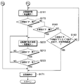
- FIG. 13 is a flowchart showing a control process executed by the air conditioner control device 12 of the present embodiment.
- the air conditioner control device 12 performs the control process of FIG. 13 only when the execution of the control process of FIG. Execute.
- the control process of FIG. 13 is periodically and repeatedly executed.
- FIG. 13 is a flowchart corresponding to FIG. 6 of the first embodiment. Steps S101, S121, and S151 in FIG. 6 are replaced with steps S102, S122, and S152 in FIG. 13, steps having the same contents as those in FIG. 6 are denoted by the same reference numerals, and description thereof will be omitted.
- step S102 the air conditioner control device 12 sets the D-seat side outlet switching device 94 to the second communication state. Thereby, the air conditioner control device 12 can flow the air that has passed through the D-seat side side face duct 39 to the D-seat side outward air outlet 915a. If the D-seat-side outlet switching device 94 is already in the second communication state, the operation is continued as it is. After step S102, the process proceeds to step S161.
- step S161 since the blower 14 is operated in step S161 in FIG. 13, if step S161 is executed following step S102, the outside of the seat D is exclusively directed outward as indicated by the arrow Ard in FIGS. Air is blown out from the outlet 915a. That is, in this case, air is blown out from the D-seat-side outward blowout port 915a as the predetermined blowout port Ps.
- step S122 the air conditioner control device 12 sets the D-seat-side and P-seat-side outlet switching devices 94 and 95 to the second communication state, respectively. Thereby, the air conditioner control device 12 can flow the air that has passed through the D-seat side side face duct 39 to the D-seat side outward air outlet 915a. Then, the air conditioner control device 12 can flow the air that has passed through the P-seat-side side face duct 40 to the P-seat-side outward air outlet 916a.
- step S122 the process proceeds to step S161.
- step S161 in FIG. 13 the blower 14 is operated. Therefore, when step S161 is executed following step S122, air is exclusively blown out of the D-seat side and P-seat side outward air outlets 915a and 916a as indicated by arrows Ard and Arp in FIG. That is, in this case, air is blown out from the D-seat side and P-seat side outward air outlets 915a and 916a as the predetermined air outlets Ps.
- step S152 the air conditioner control device 12 sets the P-seat side outlet switching device 95 to the second communication state. Thereby, the air conditioner control device 12 can flow the air that has passed through the P-seat side face duct 40 to the P-seat side outward air outlet 916a. If the P-seat-side outlet switching device 95 is already in the second communication state, the operation is continued as it is. After step S152, the process proceeds to step S161.
- step S161 since the blower 14 is operated in step S161 in FIG. 13, if step S161 is executed following step S152, the P-seat side outward air outlet 916a is exclusively used as shown by the arrow Arp in FIG. Air is blown out from the. That is, in this case, the air is blown out from the P-seat-side outward blowout port 916a as the predetermined blowout port Ps.
- the air conditioner control device 12 performs the control process of FIG. 13 as described above. Accordingly, the air conditioner control device 12 performs the following when blowing out the air from the D-seat side outward air outlet 915a while the door of the D-seat side door opening 82 is open. That is, the air conditioner control device 12 controls the D-seat-side air outlet switching device 94 to blow air through the D-seat side side face duct 39 to the D-seat side outward when blowing air in such a manner. Flow to outlet 915a.
- the air conditioner control device 12 performs the following when blowing air from the P-seat-side outward air outlet 916a while the P-seat-side door opening 84 is open. .
- the air conditioner control device 12 controls the P-seat-side outlet switching device 95 to blow out the air passing through the P-seat side face duct 40 to the P-seat side outward when the air is blown out as described above. Flow to outlet 916a.
- the D-seat-side outward air outlet 915a is provided as an air outlet different from the air-conditioning air outlets 911a to 914a.
- the blowout direction of the D-seat-side outward blowout port 915a is fixed.
- the D-seat-side outward air outlet 915a is configured such that the outlet direction of the D-seat-side outward air outlet 915a is such that the door is open from the vehicle interior side to the D-seat side door opening 82 to the outside of the vehicle interior. It is configured in advance so as to blow air through the seat-side door opening 82.
- the D-seat-side outward outlet 915a with a function of changing the outlet direction, and the D-seat-side outward outlet 915a can be simply formed.
- the performance of preventing foreign substances from entering the vehicle interior from the D-seat-side door opening 82 during opening of the door can be easily improved. This is the same for the P-seat-side outward air outlet 916a.
- the air conditioner control device 12 executes the control process shown in FIG. Accordingly, the air conditioner control device 12 performs the following when blowing out the air from the D-seat side outward air outlet 915a while the door of the D-seat side door opening 82 is open. That is, the air conditioner control device 12 controls the D-seat-side air outlet switching device 94 to blow air through the D-seat side side face duct 39 to the D-seat side outward when blowing air in such a manner. Flow to outlet 915a.
- the D-seat-side outward air outlet 915a is connected to the airflow downstream side of the D-seat-side side face duct 39 in parallel with the D-seat-side side face air outlet 911a, which is an air-conditioning air outlet.
- the D-seat-side outward air outlet 915a as a dedicated air outlet for preventing foreign substances from entering the vehicle interior from the D-seat-side door opening 82 while the door is open. Therefore, the D-seat side outward air outlet 915a can have a nozzle shape suitable for preventing foreign substances such as mosquitoes 99 from entering the vehicle interior from the D-seat side door opening 82 when the door is open. It is. As a result, for example, it is possible to improve the performance of preventing foreign substances from entering the vehicle interior from the D-seat-side door opening 82 during opening of the door. This is the same for the P-seat-side outward air outlet 916a.
- the D-seat-side outward air outlet 915a is formed in the instrument panel 91 at a position closer to the right end than the D-seat-side side face air outlet 911a in the vehicle left-right direction DR2. I have.
- the P-seat-side outward air outlet 916a is formed at a position on the instrument panel 91 closer to the left end than the P-seat-side side face air outlet 912a in the vehicle left-right direction DR2.
- the outward air outlets 915a and 916a on the D-seat side and the P-seat side are less noticeable from the occupant in the passenger compartment, so that the influence on the design in the passenger compartment can be reduced. Further, it is easy to improve the vehicle mountability of the components forming the respective outward blowout ports 915a and 916a.
- the D-seat-side side wall 91a of the instrument panel 91 is covered by the D-seat-side door 86 in a state where the D-seat-side door opening 82 is closed, and the D-seat-side outward air outlet 915a.
- the P-seat-side side wall 91b of the instrument panel 91 is covered by a P-seat-side door 88 in a state where the P-seat-side door opening 84 is closed. Is formed. Therefore, the doors 86, 88 with the door openings 82, 84 closed, make the outward air outlets 915a, 916a invisible to occupants in the vehicle interior, respectively, so that the influence on the design in the vehicle interior can be reduced. .
- this embodiment is the same as the first embodiment. Further, in the present embodiment, the effects obtained from the configuration common to the above-described first embodiment can be obtained in the same manner as the first embodiment.
- the vehicle 80 of the present embodiment includes an in-vehicle wireless device 89 that performs wireless communication with a portable device 891 carried by an occupant outside the cabin or the like. Then, the air conditioner control device 12 uses the in-vehicle wireless device 89 and the portable device 891, and immediately before the closed door openings 82 and 84 (see FIG. 1) are opened, as the predetermined air outlet Ps. The air is blown out from the side face outlets 911a and 912a. This embodiment is different from the first embodiment in this point.
- the mechanical configuration of the present embodiment is shown, for example, in FIGS. 1, 2, 4, and 5.
- the in-vehicle wireless device 89 is installed in the vehicle 80, and the portable device 891 performs wireless communication with the in-vehicle wireless device 89.
- the in-vehicle wireless device 89 and the portable device 891 constitute a part of a control system that performs collation of the portable device 891 and controls door locking and unlocking of the vehicle 80.
- the portable device 891 is also called an electronic key, for example.
- the in-vehicle wireless device 89 is electrically connected to the air conditioner control device 12 as one of a plurality of input side connection devices.
- a signal indicating, for example, the position and distance of the portable device 891 with respect to the vehicle 80 is input from the on-board wireless device 89 to the air conditioner control device 12.
- the signal from the in-vehicle wireless device 89 may be input to the air conditioner control device 12 via a control device other than the air conditioner control device 12, or may be input to the air conditioner without passing through another control device.
- the information may be directly input to the control device 12.
- the in-vehicle wireless device 89 has a control unit, and the control unit can detect the position, the distance, and the like of the portable device 891 with respect to the vehicle 80 based on the radio wave intensity received by the in-vehicle wireless device 89 from the portable device 891. is there. Therefore, the control unit of the in-vehicle wireless device 89 can determine whether or not the portable device 891 has approached the vehicle 80 and has entered the predetermined area Ax around the vehicle. Information indicating the determination result is input to the air conditioner control device 12 as a signal from the on-board wireless device 89.
- FIGS. 16A and 16B are flowcharts showing control processing executed by the air conditioner control device 12 of the present embodiment.
- the air conditioner control device 12 performs the control processing of FIGS. 16A and 16B only when the occupant operation on the cancel switch 124 is permitted.
- the control processing of FIG. 16B is executed.
- the control processing of FIGS. 16A and 16B is periodically and repeatedly executed.
- FIGS. 16A and 16B are flowcharts corresponding to FIG. 6 of the first embodiment.
- steps having the same contents as those in FIG. 6 are denoted by the same reference numerals, and description thereof will be omitted.
- step S041 if it is determined in step S041 that the ignition switch 125 is off, the process proceeds to step S053. On the other hand, when it is determined that the ignition switch 125 is not off, the process proceeds to step S171.
- step S053 the air conditioner control device 12 acquires information indicated by an input signal input from the on-vehicle wireless device 89.
- the acquired information includes information indicating whether or not the portable device 891 has approached the vehicle 80 and has entered a predetermined area Ax (see FIG. 15) around the vehicle.
- the air conditioner control device 12 determines whether or not the portable device 891 has approached the vehicle 80 and has entered a predetermined area Ax around the vehicle.
- step S053 If it is determined in step S053 that the portable device 891 has approached the vehicle 80 and has entered the predetermined area Ax around the vehicle, the process proceeds to step S071. On the other hand, when it is determined that the portable device 891 has approached the vehicle 80 and has not entered the predetermined area Ax around the vehicle, the process proceeds to step S171.
- step S071 the process proceeds to step S111, step S121, and step S161, and after step S161, the process proceeds to step S173.
- step S193 the determination regarding the elapsed time from the start of the operation of the blower 14 is performed in step S193 described later, the measurement of the elapsed time with the start of the operation of the blower 14 set to zero is performed in step S161 of the present embodiment. .
- the blower 14 is activated. Therefore, even when the door openings 82 and 84 are closed, air is blown out from the D-seat side and P-seat side side face outlets 911a and 912a.
- step S173 the air conditioner control device 12 performs the same processing as in step S051 in FIG. That is, the air conditioner control device 12 recognizes the open / closed state of the D seat side door 86 shown in FIG. 1 based on the signal from the D seat side door open / close sensor 121. Then, the air conditioner control device 12 determines whether or not the D-seat-side door opening 82 is opening the door.
- step S173 If it is determined in step S173 that the D-seat-side door opening 82 is being opened, the process proceeds to step S203. On the other hand, when it is determined that the D-seat-side door opening 82 is not opening the door, the process proceeds to step S183.
- step S183 the air conditioner control device 12 performs the same processing as in step S061 in FIG. That is, the air conditioner control device 12 recognizes the open / closed state of the P seat side door 88 shown in FIG. 1 based on the signal from the P seat side door open / close sensor 122. Then, the air conditioner control device 12 determines whether or not the P-seat-side door opening 84 is opening the door.
- step S183 If it is determined in step S183 that the P-seat-side door opening 84 is being opened, the process proceeds to step S203. On the other hand, when it is determined that the P-seat-side door opening 84 is not opening the door, the process proceeds to step S193.
- step S193 the air conditioner control device 12 determines whether or not a predetermined time TMa has elapsed since the start of the operation of the blower 14 in step S161.
- step S193 If it is determined in step S193 that the predetermined time TMa has elapsed since the start of the operation of the blower 14, the process proceeds to step S171. More specifically, step S193 is executed when the determinations in steps S173 and S183 are both “NO”. Therefore, when it is determined in step S193 that the predetermined time TMa has elapsed from the start of the operation of the blower 14 with the doors 86 and 88 closing both the D-seat side and the P-seat side door openings 82 and 84. Then, the process proceeds to step S171.
- step S193 if it is determined in step S193 that the predetermined time TMa has not elapsed from the start of the operation of the blower 14, the process proceeds to step S161.
- step S203 the air conditioner control device 12 continues the operation of the blower 14 started in step S161. After step S203, the process proceeds to step S213.
- step S203 is executed when the D-seat-side door opening 82 is opening the door, it can be said that the air conditioner control device 12 performs the following. That is, the air conditioner control device 12 controls the D-seat-side wind direction changing device 92 when blowing air from the D-seat-side side face outlet 911a while the D-seat-side door opening 82 is open. Then, it can be said that the air conditioner control device 12 directs the blowout direction of the D-seat side face outlet 911a to the outside of the vehicle compartment by controlling the D-seat side wind direction changing device 92.
- step S203 is executed when the P-seat-side door opening 84 is being opened, it can be said that the air conditioner control device 12 performs the following. That is, the air conditioner control device 12 controls the P-seat-side wind direction changing device 93 when blowing air from the P-seat-side side face outlet 912a while the P-seat-side door opening 84 is open. Then, it can be said that the air conditioner control device 12 controls the P-seat side wind direction changing device 93 to direct the blowout direction of the P-seat side face face outlet 912a to the outside of the vehicle compartment.
- the D-seat-side side face outlet 911a and the P-seat-side side face outlet 912a correspond to the predetermined outlet Ps.
- step S213 the air conditioner control device 12 acquires a signal from the D-seat-side door opening / closing sensor 121. Thereby, the air conditioner control device 12 recognizes the open / closed state of the D-seat side door 86 shown in FIG.
- the air conditioner control device 12 determines whether or not the D-seat-side door opening 82 is closed by the D-seat-side door 86.
- step S213 If it is determined in step S213 that the D-seat-side door opening 82 is closed, the process proceeds to step S223. On the other hand, if it is determined that the D-seat-side door opening 82 is not yet closed, that is, if it is determined that the D-seat-side door opening 82 is still opening the door, the process proceeds to step S203. .
- step S223 the air conditioner control device 12 acquires a signal from the P-seat-side door open / close sensor 122. Thereby, the air conditioner control device 12 recognizes the open / closed state of the P seat side door 88 shown in FIG.
- the air conditioner control device 12 determines whether or not the P-seat-side door opening 84 is closed by the P-seat-side door 88.
- step S223 If it is determined in step S223 that the P-seat-side door opening 84 is closed, the process proceeds to step S171. On the other hand, when it is determined that the P-seat-side door opening 84 is not yet closed, that is, when it is determined that the P-seat-side door opening 84 is still opening the door, the process proceeds to step S203. .
- step S171 in FIG. 16B the air conditioner control device 12 performs the same processing as in step S171 in FIG. That is, the air conditioner control device 12 stops the blower 14 that has been operating in step S161. After step S171, the process returns to step S011.
- the air conditioner control device 12 of the present embodiment performs the control processing of FIGS. 16A and 16B as described above. As a result, the air conditioner control device 12 operates the blower 14 while the door of the D-seat side door opening 82 is open as shown in FIG. Through the D-seat side face outlet 911a.
- the air conditioner control device 12 activates the blower 14 while the door of the P-seat side door opening 84 is open, and sends the air flowing from the blower 14 to the P-seat side face. The air is blown from the P-seat side face air outlet 912a through the duct 40.
- the air conditioner control device 12 controls the blower 14 even if the door openings 82 and 84 are not opened by the doors 86 and 88. Activate. Then, the air conditioner control device 12 blows out the air flowing from the blower 14 from a predetermined outlet Ps (see FIG. 9).
- the door openings 82, 84 are moved from the vehicle interior side to the vehicle exterior side with respect to the opened door openings 82, 84 without delay from the moment when any one of the door openings 82, 84 is opened by the doors 86, 88. , 84 can be blown.
- step S193 is provided as described above.
- the air conditioner control device 12 performs the following processing when the blower 14 is operated when the portable device 891 approaches the vehicle 80 and enters the predetermined area Ax. That is, in this case, the air conditioner control device 12 stops the blower 14 when a predetermined time TMa has elapsed from the start of the operation of the blower 14 with the door openings 82 and 84 closed by the doors 86 and 88. . Therefore, it is possible to prevent the operation of the blower 14 from being unnecessarily continued.
- this embodiment is the same as the first embodiment. Further, in the present embodiment, the effects obtained from the configuration common to the above-described first embodiment can be obtained in the same manner as the first embodiment.
- this embodiment is a modification based on the first embodiment, but it is also possible to combine this embodiment with the above-described second embodiment.
- the air conditioner control device 12 also executes the control process of FIG. 17 in parallel with the control process of FIG. This embodiment is different from the first embodiment in this point.
- FIG. 17 is a flowchart illustrating a control process executed by the air conditioner control device 12 of the present embodiment.
- the control process of FIG. 17 is executed in parallel with the control process of FIG. 6, and the control process of FIG. 6 and the control process of FIG. 17 are each repeatedly executed periodically.
- the air conditioner control device 12 performs the control process of FIG. 6 only when the execution of the control process of FIG. Execute the process. Since the control process of FIG. 17 is performed on the assumption that the control process of FIG. 6 is performed, the air conditioner control device 12 performs the control process of FIG. No control processing is performed.
- the air conditioner control device 12 determines whether or not the engine of the vehicle 80 has been stopped by switching the ignition switch 125 in step S014 in FIG. In short, the air conditioner control device 12 determines whether or not the engine of the vehicle 80 has been switched from the on state where the engine is operating to the off state where the engine is stopped by switching the ignition switch 125. In other words, the air conditioner control device 12 determines whether or not the occupant's operation on the ignition switch 125, which is a vehicle start switch, has switched the vehicle 80 from a running state to a non-running state. For example, when the ignition switch 125 is switched from on to off while the engine of the vehicle 80 is operating, the engine switches from on to off.
- the engine off state determined in step S014 does not include temporary engine stoppage due to idling stop or the like. This is because such a temporary stop of the engine is not an engine stop caused by switching of the ignition switch 125.
- step S014 If it is determined in step S014 that the engine of the vehicle 80 has been switched from the on state to the off state by switching the ignition switch 125, the process proceeds to step S024.
- step S014 if it is determined in step S014 that the engine of the vehicle 80 has not been switched from the ON state to the OFF state by switching the ignition switch 125, the process returns to the beginning of the flowchart. That is, the air conditioner control device 12 performs the determination in step S014 again.
- step S024 the air conditioner control device 12 sets the air conditioner unit 11 to a predetermined standby mode.
- Putting the air conditioner unit 11 into the standby mode means setting the air conditioner unit 11 into the above-described intrusion prevention mode, closing the center face blowout openings 191c and 191d (see FIG. 4), and closing the side face blowout openings 191a. 191b is released.
- the air conditioner control device 12 controls the inside / outside air switching door 16 to change the suction mode of the air conditioner unit 11 to the outside air mode. Further, the air conditioner control device 12 operates the air mix door 26, and sets the door position of the air mix door 26 to the MAXCOOL position. In addition, the air conditioner control device 12 operates the center face door 32 and closes the center face blow-out openings 191c and 191d by the center face door 32. Further, the air conditioner control device 12 activates the defroster door 33, and closes the defroster blowing opening with the defroster door 33. Further, the air conditioner control device 12 activates the foot door 34 and closes the foot outlet opening with the foot door 34. Further, the air conditioner control device 12 operates the side face doors 28 and 30, and opens the side face opening 191a and 191b on the side of the D seat and the side of the P seat by the side face doors 28 and 30.
- step S024 After the completion of the process in step S024, all of the blowout openings except for the side face blowout openings 191a and 191b on the D and P seat sides are closed.
- the function of the inside / outside air switching door 16, the air mixing door 26, the center face door 32, the defroster door 33, and the foot door 34, respectively, changes the air conditioning ventilation path which is the ventilation path of the air flowing through the air conditioning unit 11.
- Route change device That is, the air conditioner unit 11 includes a plurality of route change devices.
- the air conditioner ventilation path changed by the inside / outside air switching door 16 as the path change device is a ventilation path on the upstream side of the air flow to the blower 14 in the air conditioner unit 11.
- the air-conditioning ventilation path changed by the air mix door 26 as the path change device is a ventilation path from the upstream side to the downstream side of the air flow across the air mix door 26 shown in FIG.
- the air conditioner ventilation path changed by the center face door 32 as the path changing device is a ventilation path heading to the center face blowout openings 191c and 191d in the air conditioner unit 11.
- the air conditioner ventilation path changed by the defroster door 33 as the path changing device is a ventilation path heading toward the defroster outlet opening in the air conditioner unit 11.
- the air conditioner ventilation path changed by the foot door 34 as the path changing device is a ventilation path heading toward the foot outlet in the air conditioner unit 11.
- the air conditioner ventilation path established by each of the path change devices is controlled by the air conditioner controller 12 from the predetermined outlet Ps during the door opening of the door openings 82 and 84 in the control process of FIG.
- This is a state established when air is blown out.
- the state of the air conditioner ventilation path established by the air mix door 26 is a state established by the air conditioner controller 12 in steps S071 and S131 of FIG.
- the D-seat-side side face outlet 911a and the P-seat-side side face outlet 912a correspond to the predetermined outlet Ps.
- the air conditioner control device 12 performs the following as a result of the control processing of FIG. That is, when the engine of the vehicle 80 is stopped, it can be said that the air conditioner control device 12 operates each of the route change devices so that the target state of the air conditioner ventilation route is established in advance regardless of whether the doors 86 and 88 are opened or closed. .
- the target state of the air conditioner ventilation path is the state of the air conditioner ventilation path established when the air conditioner controller 12 blows air from the predetermined outlet Ps while one or both of the door openings 82 and 84 are open. It is.
- this embodiment is the same as the first embodiment. Further, in the present embodiment, the effects obtained from the configuration common to the above-described first embodiment can be obtained in the same manner as the first embodiment.
- the air conditioner control device 12 sets the target condition of the air conditioner ventilation path in advance regardless of whether the doors 86 and 88 are open or closed. Activate the change device. That is, when the vehicle 80 is switched from a state in which the vehicle can travel to a state in which the vehicle cannot travel by the occupant operation on the ignition switch 125, the air conditioner control device 12 sets the target state in advance regardless of the opening and closing of the doors 86 and 88. Each route changing device is operated so as to be established.
- the target state of the air conditioner ventilation path is the state of the air conditioner ventilation path established when the air conditioner controller 12 blows air from the predetermined outlet Ps while one or both of the door openings 82 and 84 are open. It is.
- the door openings 82, 84 are moved from the vehicle interior side to the vehicle exterior side with respect to the opened door openings 82, 84. It is possible to blow out air so as to pass through.
- this embodiment is a modification based on the first embodiment, but it is also possible to combine this embodiment with the above-described second embodiment or the third embodiment.
- the P-seat-side outward air outlet 916a of the present embodiment is not formed on the P-seat-side side wall 91b of the instrument panel 91.
- the P-seat-side outward air outlet 916a is formed on a surface of the instrument panel 91 facing the vehicle rear side.
- the D-seat-side outward air outlet 915a is not formed on the D-seat-side side wall 91a of the instrument panel 91.
- the D-seat-side outward air outlet 915a is formed on a surface of the instrument panel 91 facing the vehicle rear side.
- the D-seat-side outward air outlet 915a is formed in the instrument panel 91 at a position closer to the right end than the D-seat-side side face air outlet 911a in the vehicle left-right direction DR2.
- the P-seat-side outward air outlet 916a is formed at a position on the instrument panel 91 closer to the left end than the P-seat-side side face air outlet 912a in the vehicle left-right direction DR2. This is the same as in the first embodiment.
- this embodiment is the same as the second embodiment. Then, in the present embodiment, the effects achieved by the configuration common to the above-described second embodiment can be obtained in the same manner as in the second embodiment.
- the vehicle 80 includes the center face opening / closing device 13. This center face opening / closing device 13 replaces the center face door 32 of the second embodiment.
- the center face opening / closing device 13 is a device attached to the air conditioner unit 11, and is disposed between the two center face outlet openings 191c, 191d and the entrance ends 411, 421 of the two center face ducts 41, 42. Is done. That is, the inlet ends 411, 421 of the two center face ducts 41, 42 are connected to the two center face outlet openings 191c, 191d via the center face opening / closing device 13, respectively.
- the center face opening / closing device 13 opens and closes a ventilation path between the entrance ends 411, 421 of the center face ducts 41, 42 and the center face outlet openings 191c, 191d. That is, the center face opening / closing device 13 opens and closes the two center face blowing openings 191c and 191d outside the air conditioner unit 11.
- the center face opening openings 191c and 191d are closed by the center face opening / closing device 13 in steps S091, S111, and S141.
- this embodiment is the same as the second embodiment. Then, in the present embodiment, the effects achieved by the configuration common to the above-described second embodiment can be obtained in the same manner as in the second embodiment.
- the center face opening / closing device 13 is attached to the air conditioner unit 11, and opens and closes the center face blowing openings 191c and 191d. Therefore, even when the air conditioner unit 11 is not provided with the center face door 32, the air volume to be blown out from the predetermined outlet Ps while the doors of the D-seat side door openings 82 and 84 are open can be obtained. It is possible to obtain as much as.
- the D-seat-side outward air outlet 915a and the P-seat-side outward air outlet 916a correspond to the above-described predetermined air outlet Ps.
- one side in the vehicle left-right direction DR2 is the vehicle right side
- the other side in the vehicle left-right direction DR2 is the vehicle left side
- one side in the vehicle left-right direction DR2 may be the vehicle left side
- the other side in the vehicle left-right direction DR2 may be the vehicle right side.
- the vehicle 80 has the cancel switch 124, but the cancel switch 124 is not an essential component. If there is no cancel switch 124, for example, the air conditioner control device 12 executes the control process of FIG. 6 assuming that the execution of the control process of FIG. 6 is permitted. This is the same for the control processing shown in the flowchart corresponding to FIG. 6 in the second and subsequent embodiments.
- steps S021, S031, and S041 are provided in the flowchart illustrated in FIG. 6, but these steps are not essential. For example, when all of steps S021, S031, and S041 are not present, step S011 is also unnecessary, and the flowchart in that case starts from step S051.
- the suction mode of the air conditioner unit 11 is set to the outside air mode, but this is an example.
- the suction mode of the air conditioner unit 11 may not be set to the outside air mode. This is the same in the steps of performing the same processing as steps S071 and S131 in FIG. 6 in the flowcharts other than FIG.
- steps S071 and S131 of the flowchart shown in FIG. 6 in the first embodiment described above the door position of the air mix door 26 is set to the MAXCOOL position, but this is an example.
- the door position of the air mix door 26 may not be set to the MAXCOOL position. This is the same in the steps of performing the same processing as steps S071 and S131 in FIG. 6 in the flowcharts other than FIG.
- the control processing executed by the air conditioner control device 12 is performed when the D-seat-side door opening 82 is opened and when the P-seat-side door opening 84 is opened.
- the air is blown out from the predetermined outlet Ps corresponding to each of the cases where the air is opened.
- the control process of the air conditioner control device 12 performs the predetermined blowing of air in response to only one of the case where the D-seat side door opening 82 is opened and the case where the P-seat side door opening 84 is opened. It may blow out from the outlet Ps.
- the blower 14 in the inside air mode of the air conditioner unit 11, the blower 14 is prevented from drawing in outside air, but this is an example.
- the inside air mode may be a mode in which the blower 14 sucks more inside air than outside air.
- the blower 14 in the outside air mode of the air conditioner unit 11, the blower 14 is prevented from drawing in the inside air, but this is an example.
- the outside air mode may be a mode in which the blower 14 sucks more outside air than inside air.
- the air conditioner control device 12 sets the outlet switching devices 94 and 95 to the first communication state, respectively.
- the timing at which the outlet switching devices 94 and 95 are brought into the first communication state is not limited to the start of air conditioning in the passenger compartment.
- the outlet switching devices 94 and 95 may be respectively set to the first communication state. In that case, if the outlet switching devices 94 and 95 are already in the first communication state, the operation is continued as it is.
- the in-vehicle wireless device 89 in FIG. 14 determines whether or not the portable device 891 has approached the vehicle 80 and has entered a predetermined area Ax around the vehicle. The operation may not be performed by the machine 89 but may be performed by the air conditioner control device 12.
- the inside / outside air switching door 16, the air mix door 26, the center face door 32, the defroster door 33, and the foot door 34 are path change devices.
- the air conditioner control device 12 sets the target state of the air conditioner ventilation path in advance regardless of whether the doors 86 and 88 are opened or closed. Activate the rerouting device.
- this is only an example.
- the air conditioner control device 12 does not need to operate all the route change devices so that the target state of the air conditioner ventilation route is established in advance regardless of the opening and closing of the doors 86 and 88. May be activated.
- the air conditioner control device 12 is configured to open the D-seat side and the P-seat side door openings 82 and 84 while one or both doors are open. Then, the air blown by the blower 14 is blown out from the predetermined outlet Ps.
- the D-side seat side face outlet 911a and the P-side seat side face outlet 912a correspond to the predetermined outlet Ps. However, this is only an example. 20 to 22, the outlets other than the side face outlets 911a and 912a may correspond to the predetermined outlet Ps.
- FIG. 20 shows a configuration in which the center face outlets 913a and 914a correspond to the predetermined outlets Ps in addition to the side face outlets 911a and 912a.
- the two center outlets 913 and 914 are provided with wind direction change devices 961 and 962, respectively, and the wind direction change devices 961 and 962 serve to blow air from the center face outlets 913a and 914a. Change the blow direction of each. For example, when the P-seat-side door opening 84 is closed and while the D-seat-side door opening 82 is open, the blowout directions of the center face outlets 913a and 914a are all as indicated by the arrow Arc. It is directed to the D seat side door opening 82 side. When air is blown out from the center face outlets 913a and 914a, the center face outlets 191c and 191d are opened.
- FIG. 21 shows a configuration in which the predetermined outlet Ps corresponds to the side face outlets 911a and 912a, the D-side seat side defroster outlet 431a, and the P-side seat side defroster outlet 432a.
- the temperature adjustment case 19 has a plurality of defroster outlets 191e, 191f, 191g, and 191h.
- the D-seat side defroster duct 431, the P-seat side defroster duct 432, and the two center defroster ducts 433 and 434 are connected to the defroster outlet openings 191e, 191f, 191g and 191h, respectively.
- Each of the defroster ducts 431, 432, 433, and 434 has an outlet end 431a, 432a, 433a, and 434a that is a downstream end of the air flow, and each of the outlet ends 431a, 432a, 433a, and 434a blows air. Acts as an exit. That is, the outlet end 431a of the D-seat side defroster duct 431 is the D-seat side defroster outlet 431a, and the outlet end 432a of the P-seat side defroster duct 432 is the P-seat side defroster outlet 432a.
- the outlet ends 433a and 434a of the two center defroster ducts 433 and 434 are the center defroster outlets 433a and 434a.
- the D-seat-side side defroster outlet 431a is open toward the side window of the D-seat-side door 86 at a position close to the front of the vehicle and close to the right of the vehicle in the vehicle interior.
- the P-seat side defroster outlet 432a opens into the vehicle interior toward the side window of the P-seat-side door 88 at a position near the front end of the vehicle and near the left end of the vehicle in the vehicle interior.
- the center defroster outlets 433a and 434a open toward the front window toward the front window at a position near the front end of the vehicle and at a central portion in the vehicle left-right direction DR2.
- the air blown by the blower 14 is blown out as shown by arrows Ard and Arrow Aw in FIG. That is, the air flowed by the blower 14 is blown out from the D-seat-side side face air outlet 911a and the D-seat-side side defroster air outlet 431a as the predetermined air outlets Ps.
- the door of the P-seat side door opening 84 is open, the air flowing from the blower 14 is blown out from the P-seat side face exhaust port 912a and the P-seat side defroster outlet 432a as the predetermined outlets Ps. .
- the blowing direction of the D-seat-side side defroster outlet 431a is such that the D-seat-side door opening 82 is moved from the inside of the vehicle to the outside of the cabin with respect to the D-seat-side door opening 82 when the door is open. It is set in advance so that air is blown out through the air. Further, the blowing direction of the P-seat-side side defroster outlet 432a is such that air is blown from the cabin side to the P-seat-side door opening 84 during opening of the door through the P-seat-side door opening 84. Is set in advance.
- FIG. 22 shows a configuration in which the predetermined outlet Ps corresponds to the D-seat side foot outlet 441a and the P-seat side foot outlet 442a in addition to the side face outlets 911a and 912a.
- the D-seat side foot duct 441 and the P-seat side foot duct 442 are provided, and the respective foot ducts 441 and 442 are connected to the foot outlet openings of the temperature control unit case 19.
- foot ducts 441 and 442 have outlet ends 441a and 442a, which are downstream ends of the air flow, respectively, and the outlet ends 441a and 442a function as outlets for blowing air. That is, the outlet end 441a of the D seat side foot duct 441 is the D seat side foot outlet 441a, and the outlet end 442a of the P seat side foot duct 442 is the P seat side foot outlet 442a.
- the D-seat side foot outlet 441a opens into the vehicle cabin near the feet of the occupant seated on the driver's seat 901 in the vehicle cabin.
- the P-seat side foot air outlet 442a opens into the passenger compartment near the feet of the occupant sitting on the passenger seat 902 in the passenger compartment.
- the air flowing from the blower 14 is blown out as shown by arrows Ard and Arf in FIG. That is, the air flowed by the blower 14 is blown out from the D-seat side face face outlet 911a and the D-seat side foot outlet 441a as the predetermined outlets Ps.
- the door of the P-seat-side door opening 84 is open, the air flowing from the blower 14 is blown out from the P-seat-side side face outlet 912a and the P-seat-side foot outlet 442a as the predetermined outlets Ps.
- the blowing direction of the D-seat-side foot outlet 441a is from the inside of the vehicle to the outside of the cabin with respect to the D-seat-side door opening 82 during opening of the door through the D-seat-side door opening 82.
- the air is blown out beforehand.
- the blowing direction of the P-seat side foot air outlet 442a is such that air is blown from the inside of the cabin to the outside of the cabin with respect to the P-seat side door opening 84 during opening of the door via the P-seat side door opening 84. Is set in advance as follows.
- the air conditioning ducts 39 to 42 of the vehicle 80, the plurality of outlets 911, 912, 913, 914, and the plurality of wind direction changing devices 92, 93 and the like are not included in the air blowing device 10, but this is an example. For example, they may be included in the air blowing device 10. Further, in the second embodiment, the plurality of outlet switching devices 94 and 95 and the plurality of outward blowing portions 915 and 916 may be included in the air blowing device 10.
- the predetermined outlet Ps blows air from the vehicle interior side to the door opening to the vehicle exterior through the door opening. Since the door openings are the door openings 82 and 84 on the D-seat side and the P-seat side, the door openings are openings for occupants to enter and exit. The door openings are openings for occupants to enter and exit. It does not have to be.
- step S024 of the flowchart shown in FIG. 17 the air conditioner control device 12 does not operate the D-seat side and P-seat side wind direction change devices 92 and 93, but this is an example.
- the air conditioner control device 12 may set both the D-seat side and P-seat side wind direction change devices 92 and 93 to the outward air outlet mode in addition to setting the air conditioner unit 11 to the standby mode.
- the sensor when the acquisition of the external environment information (for example, the relative humidity outside the vehicle) of the vehicle 80 from the sensor is described, the sensor is abolished and the server or the cloud outside the vehicle 80 is used. It is also possible to receive the external environment information. Alternatively, the sensor may be eliminated, related information related to the external environment information may be acquired from a server or a cloud outside the vehicle 80, and the external environment information may be estimated from the acquired related information.
- the external environment information for example, the relative humidity outside the vehicle
- the control device activates the blower and causes the air to flow through the air conditioning duct.
- the predetermined air outlet blows air from the inside of the vehicle compartment to the outside of the vehicle compartment with respect to the door opening portion during opening of the door through the door opening portion.
- the air-conditioning air flowing out of the air-conditioning unit when the air-conditioning unit air-conditions the passenger compartment also flows through the air-conditioning duct to which the predetermined outlet is connected.
- the predetermined air outlet blows out the conditioned air passing through the air-conditioning duct. Therefore, the predetermined outlet is not a dedicated outlet for blowing out air for the purpose of suppressing entry of foreign matter into the vehicle interior. That is, it is possible to divert an air-conditioning outlet used for air-conditioning of the vehicle interior as a predetermined outlet. Therefore, it is possible to improve the mountability of the air blowing device on the vehicle.
- a wind direction changing device for changing a blowing direction of air blown out from a predetermined outlet. Then, when blowing out air from the predetermined outlet while the door is open, the control device controls the wind direction changing device to direct the blowing direction of the predetermined outlet to the outside of the vehicle compartment. Therefore, in order to prevent foreign substances such as mosquitoes from entering the vehicle interior from the door opening when the door is open, it is possible to set the air-conditioning air outlet used as the predetermined air outlet to the appropriate direction. It is.
- the direction of the air blown out from the predetermined outlet is such that the air blows out from the inside of the vehicle with respect to the door opening through the door opening toward the outside of the vehicle. It is configured in advance so that Therefore, it is not necessary to provide the function of changing the blowing direction to the predetermined outlet, and the predetermined outlet can be simply formed. Thereby, for example, there is a merit that it is easy to improve the performance of preventing foreign substances from entering the vehicle interior from the door opening portion when the door is opened.
- the predetermined outlet is connected to the airflow downstream side of the air conditioning duct in parallel with the air conditioning outlet that blows out conditioned air when the air conditioner unit performs air conditioning in the vehicle interior.
- An outlet switching device is provided for switching the ventilation path so that the air passing through the air conditioning duct flows to either the predetermined outlet or the air conditioning outlet. Then, when blowing out air from the predetermined air outlet while the door is open, the control device controls the air outlet switching device to flow the air passing through the air conditioning duct to the predetermined air outlet.
- the predetermined outlet can be formed in a nozzle shape suitable for preventing foreign substances such as mosquitoes from entering the vehicle interior from the door opening during the door opening. As a result, for example, it is possible to improve the performance of preventing foreign matter from entering the vehicle interior from the door opening during the door opening.
- the vehicle has an instrument panel.
- the air-conditioning outlet is a side face outlet that opens into the vehicle cabin at a position near an end of the instrument panel in the left-right direction of the vehicle.
- the predetermined outlet is formed in the instrument panel at a position closer to the end than the air-conditioning outlet in the left-right direction of the vehicle. Accordingly, the predetermined air outlet is less noticeable to the occupant in the vehicle compartment, so that the influence on the design in the vehicle compartment can be reduced.
- the instrument panel has, at the left-right end, a side wall facing the outside of the vehicle compartment in the left-right direction of the vehicle.
- the side wall is covered by a door with the door opening closed, and a predetermined outlet is formed on the side wall. Therefore, the door with the door opening closed can make the predetermined air outlet invisible to the occupant in the vehicle interior, so that the influence on the design in the vehicle interior can be reduced.
- a first air passage for passing the air flowing from the blower to the heat exchanger and the air passage provided in parallel with the first air passage are provided inside the air conditioner unit.
- a second air passage for flowing air bypassing the heat exchanger is formed.
- the air conditioner unit has a passage opening / closing device for opening / closing the second air passage. The control device causes the passage opening / closing device to open the second air passage when blowing air from the predetermined outlet while the door is open. Therefore, when air is blown out from the predetermined outlet while the door is open, it is possible to avoid an increase in ventilation resistance due to the heat exchanger in the air conditioner unit. As a result, it is possible to increase the amount of air blown from the predetermined outlet while the door is open.
- the air conditioner unit is configured to be switchable between a plurality of suction modes including an outside air mode for guiding air outside the vehicle compartment to the blower.
- the control device sets the air conditioner unit to the outside air mode when blowing air from the predetermined outlet while the door is open. Therefore, it is possible to prevent the air blown out from the predetermined outlet from being drawn into the vehicle interior by the blower. As a result, it is possible to improve the performance of preventing foreign matter from entering the vehicle interior from the door opening during the door opening, as compared with a case where the blower sucks inside air, for example.
- the air conditioner unit can flow air from the air conditioner unit to a center face outlet that is located at a central portion of the vehicle in the lateral direction of the vehicle and that opens into the vehicle interior. Is provided.
- the center face outlet is a different outlet from the predetermined outlet. Then, when blowing out air from the predetermined outlet while the door is open, the control device stops blowing air from the center face outlet into the vehicle interior. Accordingly, it is possible to secure a large air volume of the air blown out from the predetermined outlet in response to stopping the air flow to the center face outlet which is some distance from the door opening.
- the control device supplies air from the predetermined outlet during the opening of the door, on condition that the outside air temperature is equal to or higher than the predetermined lower limit of the external air temperature and equal to or lower than the predetermined upper limit of the external air temperature.
- the air conditioner unit has a route changing device that changes an air conditioner ventilation route that is a ventilation route of air flowing through the air conditioner unit. Then, when the vehicle is switched from a state in which the vehicle can travel to a state in which the vehicle cannot travel by an occupant operation on the vehicle start switch, the control device sets an air conditioner that is established when air is blown out from a predetermined outlet while the door is open.
- the path changing device is operated so that the target state of the ventilation path is established in advance regardless of whether the door is opened or closed. Therefore, immediately after the door opening is opened by the door, it is possible to blow air from the inside of the cabin to the outside of the cabin through the door opening with respect to the door opening.
- the control device recognizes that the door has opened the door opening based on a signal from the door opening / closing sensor that detects opening / closing of the door. Therefore, the control device can easily obtain information as to whether or not the door has opened the door opening.
- the vehicle is provided with an occupant operation switch for switching between permission and non-permission for blowing air from the predetermined outlet while the door is open. Then, only when the occupant operation on the occupant operation switch permits the air to be blown out from the predetermined outlet while the door is open, the control device causes the predetermined outlet to blow air while the door is open. Therefore, it is possible to stop blowing air from the predetermined outlet while the door is open, according to the occupant's intention.
- the control device performs the following. That is, when a portable device that performs wireless communication with an on-vehicle wireless device installed in a vehicle approaches the vehicle and enters a predetermined area around the vehicle, even if the door opening is not opened by the door, the control device performs Then, the blower is operated, and the air flowing from the blower is blown out from a predetermined outlet. Therefore, it is possible to blow air from the interior side of the vehicle with respect to the door opening through the door opening without delay from the moment when the door opening is opened by the door.
- control device is configured to start the operation of the blower with the door opening closed by the door when the portable device approaches the vehicle and enters the predetermined area and activates the blower.
- the blower is stopped. Therefore, it is possible to avoid unnecessary operation of the blower.
Landscapes
- Physics & Mathematics (AREA)
- Thermal Sciences (AREA)
- Engineering & Computer Science (AREA)
- Mechanical Engineering (AREA)
- Air-Conditioning For Vehicles (AREA)
Applications Claiming Priority (2)
| Application Number | Priority Date | Filing Date | Title |
|---|---|---|---|
| JP2018-179184 | 2018-09-25 | ||
| JP2018179184A JP7172358B2 (ja) | 2018-09-25 | 2018-09-25 | 空気吹出装置 |
Publications (1)
| Publication Number | Publication Date |
|---|---|
| WO2020066450A1 true WO2020066450A1 (ja) | 2020-04-02 |
Family
ID=69949962
Family Applications (1)
| Application Number | Title | Priority Date | Filing Date |
|---|---|---|---|
| PCT/JP2019/033937 Ceased WO2020066450A1 (ja) | 2018-09-25 | 2019-08-29 | 空気吹出装置 |
Country Status (2)
| Country | Link |
|---|---|
| JP (1) | JP7172358B2 (enExample) |
| WO (1) | WO2020066450A1 (enExample) |
Cited By (1)
| Publication number | Priority date | Publication date | Assignee | Title |
|---|---|---|---|---|
| US12600321B2 (en) | 2022-12-28 | 2026-04-14 | Honda Motor Co., Ltd. | Defroster interior structure |
Citations (4)
| Publication number | Priority date | Publication date | Assignee | Title |
|---|---|---|---|---|
| JP2004256092A (ja) * | 2003-02-03 | 2004-09-16 | Denso Corp | 移動体の空調装置 |
| JP2008105486A (ja) * | 2006-10-24 | 2008-05-08 | Toyota Motor Corp | ダスト低減装置 |
| JP2008120131A (ja) * | 2006-11-08 | 2008-05-29 | Calsonic Kansei Corp | ダスト低減装置 |
| JP2010030358A (ja) * | 2008-07-25 | 2010-02-12 | Denso Corp | 車両用空調装置 |
Family Cites Families (5)
| Publication number | Priority date | Publication date | Assignee | Title |
|---|---|---|---|---|
| JPH08175161A (ja) * | 1994-12-26 | 1996-07-09 | Calsonic Corp | 車両用空調装置および車両用空調方法 |
| JP4353053B2 (ja) | 2004-10-04 | 2009-10-28 | 株式会社デンソー | 車両用空調装置 |
| JP2008114757A (ja) | 2006-11-06 | 2008-05-22 | Calsonic Kansei Corp | ダスト低減装置 |
| DE102010033515A1 (de) | 2010-08-05 | 2012-02-09 | Gm Global Technology Operations Llc (N.D.Ges.D. Staates Delaware) | Vorrichtung und Verfahren zum Vermeiden des Eindringens von Fremdpartikeln in einen Fahrzeuginnenraum |
| JP2018105556A (ja) | 2016-12-27 | 2018-07-05 | トヨタホーム株式会社 | 建物の送風設備 |
-
2018
- 2018-09-25 JP JP2018179184A patent/JP7172358B2/ja active Active
-
2019
- 2019-08-29 WO PCT/JP2019/033937 patent/WO2020066450A1/ja not_active Ceased
Patent Citations (4)
| Publication number | Priority date | Publication date | Assignee | Title |
|---|---|---|---|---|
| JP2004256092A (ja) * | 2003-02-03 | 2004-09-16 | Denso Corp | 移動体の空調装置 |
| JP2008105486A (ja) * | 2006-10-24 | 2008-05-08 | Toyota Motor Corp | ダスト低減装置 |
| JP2008120131A (ja) * | 2006-11-08 | 2008-05-29 | Calsonic Kansei Corp | ダスト低減装置 |
| JP2010030358A (ja) * | 2008-07-25 | 2010-02-12 | Denso Corp | 車両用空調装置 |
Cited By (1)
| Publication number | Priority date | Publication date | Assignee | Title |
|---|---|---|---|---|
| US12600321B2 (en) | 2022-12-28 | 2026-04-14 | Honda Motor Co., Ltd. | Defroster interior structure |
Also Published As
| Publication number | Publication date |
|---|---|
| JP2020050028A (ja) | 2020-04-02 |
| JP7172358B2 (ja) | 2022-11-16 |
Similar Documents
| Publication | Publication Date | Title |
|---|---|---|
| JP5189732B2 (ja) | 自動車用空気調和装置 | |
| US11161390B2 (en) | Air flow control system | |
| KR102028884B1 (ko) | 차량용 공조장치 제어 방법 | |
| JP4525431B2 (ja) | 車両用換気装置 | |
| EP2500192A1 (en) | Vehicle air conditioning apparatus | |
| KR20210056227A (ko) | 차량용 공조장치 | |
| JP7172358B2 (ja) | 空気吹出装置 | |
| CN103260916A (zh) | 车辆用空调系统 | |
| JP2010264826A (ja) | 車両用空調装置 | |
| JP3675160B2 (ja) | 車両用シート空調装置 | |
| JP2008149998A (ja) | 車両用空調装置 | |
| WO2014103610A1 (ja) | 車両用空気調和システム | |
| JP2003136936A (ja) | 車両用空調装置 | |
| JP6164107B2 (ja) | 車両用空調装置 | |
| JP3680442B2 (ja) | 車両後席用空調装置 | |
| JP4609216B2 (ja) | 車両用空調装置 | |
| JPH0413212Y2 (enExample) | ||
| JP2005349854A (ja) | 車両換気装置 | |
| JP2010064661A (ja) | 車両用空調制御装置 | |
| JP3680443B2 (ja) | 車両後席用空調装置 | |
| KR101694041B1 (ko) | 개별공조를 위한 후석 통합도어를 갖는 차량공조장치 | |
| JPH0880726A (ja) | バス用空調装置 | |
| JP2012121482A (ja) | 車両用空気調和システム | |
| JPH1076836A (ja) | 車両用空気調和装置 | |
| JP4503446B2 (ja) | 車両用換気装置 |
Legal Events
| Date | Code | Title | Description |
|---|---|---|---|
| 121 | Ep: the epo has been informed by wipo that ep was designated in this application |
Ref document number: 19867469 Country of ref document: EP Kind code of ref document: A1 |
|
| NENP | Non-entry into the national phase |
Ref country code: DE |
|
| 122 | Ep: pct application non-entry in european phase |
Ref document number: 19867469 Country of ref document: EP Kind code of ref document: A1 |