WO2020066098A1 - 建設機械 - Google Patents
建設機械 Download PDFInfo
- Publication number
- WO2020066098A1 WO2020066098A1 PCT/JP2019/016724 JP2019016724W WO2020066098A1 WO 2020066098 A1 WO2020066098 A1 WO 2020066098A1 JP 2019016724 W JP2019016724 W JP 2019016724W WO 2020066098 A1 WO2020066098 A1 WO 2020066098A1
- Authority
- WO
- WIPO (PCT)
- Prior art keywords
- pump
- engine
- hydraulic pump
- torque
- hydraulic
- Prior art date
- Legal status (The legal status is an assumption and is not a legal conclusion. Google has not performed a legal analysis and makes no representation as to the accuracy of the status listed.)
- Ceased
Links
Images


Classifications
-
- E—FIXED CONSTRUCTIONS
- E02—HYDRAULIC ENGINEERING; FOUNDATIONS; SOIL SHIFTING
- E02F—DREDGING; SOIL-SHIFTING
- E02F9/00—Component parts of dredgers or soil-shifting machines, not restricted to one of the kinds covered by groups E02F3/00 - E02F7/00
- E02F9/26—Indicating devices
-
- F—MECHANICAL ENGINEERING; LIGHTING; HEATING; WEAPONS; BLASTING
- F02—COMBUSTION ENGINES; HOT-GAS OR COMBUSTION-PRODUCT ENGINE PLANTS
- F02D—CONTROLLING COMBUSTION ENGINES
- F02D41/00—Electrical control of supply of combustible mixture or its constituents
- F02D41/22—Safety or indicating devices for abnormal conditions
-
- E—FIXED CONSTRUCTIONS
- E02—HYDRAULIC ENGINEERING; FOUNDATIONS; SOIL SHIFTING
- E02F—DREDGING; SOIL-SHIFTING
- E02F9/00—Component parts of dredgers or soil-shifting machines, not restricted to one of the kinds covered by groups E02F3/00 - E02F7/00
- E02F9/20—Drives; Control devices
- E02F9/2004—Control mechanisms, e.g. control levers
-
- E—FIXED CONSTRUCTIONS
- E02—HYDRAULIC ENGINEERING; FOUNDATIONS; SOIL SHIFTING
- E02F—DREDGING; SOIL-SHIFTING
- E02F9/00—Component parts of dredgers or soil-shifting machines, not restricted to one of the kinds covered by groups E02F3/00 - E02F7/00
- E02F9/20—Drives; Control devices
- E02F9/2058—Electric or electro-mechanical or mechanical control devices of vehicle sub-units
- E02F9/2062—Control of propulsion units
- E02F9/2066—Control of propulsion units of the type combustion engines
-
- E—FIXED CONSTRUCTIONS
- E02—HYDRAULIC ENGINEERING; FOUNDATIONS; SOIL SHIFTING
- E02F—DREDGING; SOIL-SHIFTING
- E02F9/00—Component parts of dredgers or soil-shifting machines, not restricted to one of the kinds covered by groups E02F3/00 - E02F7/00
- E02F9/20—Drives; Control devices
- E02F9/22—Hydraulic or pneumatic drives
- E02F9/2221—Control of flow rate; Load sensing arrangements
- E02F9/2232—Control of flow rate; Load sensing arrangements using one or more variable displacement pumps
- E02F9/2235—Control of flow rate; Load sensing arrangements using one or more variable displacement pumps including an electronic controller
-
- E—FIXED CONSTRUCTIONS
- E02—HYDRAULIC ENGINEERING; FOUNDATIONS; SOIL SHIFTING
- E02F—DREDGING; SOIL-SHIFTING
- E02F9/00—Component parts of dredgers or soil-shifting machines, not restricted to one of the kinds covered by groups E02F3/00 - E02F7/00
- E02F9/20—Drives; Control devices
- E02F9/22—Hydraulic or pneumatic drives
- E02F9/2246—Control of prime movers, e.g. depending on the hydraulic load of work tools
-
- E—FIXED CONSTRUCTIONS
- E02—HYDRAULIC ENGINEERING; FOUNDATIONS; SOIL SHIFTING
- E02F—DREDGING; SOIL-SHIFTING
- E02F9/00—Component parts of dredgers or soil-shifting machines, not restricted to one of the kinds covered by groups E02F3/00 - E02F7/00
- E02F9/20—Drives; Control devices
- E02F9/22—Hydraulic or pneumatic drives
- E02F9/226—Safety arrangements, e.g. hydraulic driven fans, preventing cavitation, leakage, overheating
-
- E—FIXED CONSTRUCTIONS
- E02—HYDRAULIC ENGINEERING; FOUNDATIONS; SOIL SHIFTING
- E02F—DREDGING; SOIL-SHIFTING
- E02F9/00—Component parts of dredgers or soil-shifting machines, not restricted to one of the kinds covered by groups E02F3/00 - E02F7/00
- E02F9/26—Indicating devices
- E02F9/267—Diagnosing or detecting failure of vehicles
-
- F—MECHANICAL ENGINEERING; LIGHTING; HEATING; WEAPONS; BLASTING
- F02—COMBUSTION ENGINES; HOT-GAS OR COMBUSTION-PRODUCT ENGINE PLANTS
- F02B—INTERNAL-COMBUSTION PISTON ENGINES; COMBUSTION ENGINES IN GENERAL
- F02B63/00—Adaptations of engines for driving pumps, hand-held tools or electric generators; Portable combinations of engines with engine-driven devices
- F02B63/06—Adaptations of engines for driving pumps, hand-held tools or electric generators; Portable combinations of engines with engine-driven devices for pumps
-
- F—MECHANICAL ENGINEERING; LIGHTING; HEATING; WEAPONS; BLASTING
- F02—COMBUSTION ENGINES; HOT-GAS OR COMBUSTION-PRODUCT ENGINE PLANTS
- F02D—CONTROLLING COMBUSTION ENGINES
- F02D29/00—Controlling engines, such controlling being peculiar to the devices driven thereby, the devices being other than parts or accessories essential to engine operation, e.g. controlling of engines by signals external thereto
- F02D29/02—Controlling engines, such controlling being peculiar to the devices driven thereby, the devices being other than parts or accessories essential to engine operation, e.g. controlling of engines by signals external thereto peculiar to engines driving vehicles; peculiar to engines driving variable pitch propellers
-
- F—MECHANICAL ENGINEERING; LIGHTING; HEATING; WEAPONS; BLASTING
- F02—COMBUSTION ENGINES; HOT-GAS OR COMBUSTION-PRODUCT ENGINE PLANTS
- F02D—CONTROLLING COMBUSTION ENGINES
- F02D29/00—Controlling engines, such controlling being peculiar to the devices driven thereby, the devices being other than parts or accessories essential to engine operation, e.g. controlling of engines by signals external thereto
- F02D29/04—Controlling engines, such controlling being peculiar to the devices driven thereby, the devices being other than parts or accessories essential to engine operation, e.g. controlling of engines by signals external thereto peculiar to engines driving pumps
-
- F—MECHANICAL ENGINEERING; LIGHTING; HEATING; WEAPONS; BLASTING
- F02—COMBUSTION ENGINES; HOT-GAS OR COMBUSTION-PRODUCT ENGINE PLANTS
- F02D—CONTROLLING COMBUSTION ENGINES
- F02D31/00—Use of speed-sensing governors to control combustion engines, not otherwise provided for
- F02D31/001—Electric control of rotation speed
-
- F—MECHANICAL ENGINEERING; LIGHTING; HEATING; WEAPONS; BLASTING
- F02—COMBUSTION ENGINES; HOT-GAS OR COMBUSTION-PRODUCT ENGINE PLANTS
- F02D—CONTROLLING COMBUSTION ENGINES
- F02D41/00—Electrical control of supply of combustible mixture or its constituents
- F02D41/02—Circuit arrangements for generating control signals
- F02D41/14—Introducing closed-loop corrections
- F02D41/1497—With detection of the mechanical response of the engine
-
- F—MECHANICAL ENGINEERING; LIGHTING; HEATING; WEAPONS; BLASTING
- F04—POSITIVE - DISPLACEMENT MACHINES FOR LIQUIDS; PUMPS FOR LIQUIDS OR ELASTIC FLUIDS
- F04B—POSITIVE-DISPLACEMENT MACHINES FOR LIQUIDS; PUMPS
- F04B49/00—Control, e.g. of pump delivery, or pump pressure of, or safety measures for, machines, pumps, or pumping installations, not otherwise provided for, or of interest apart from, groups F04B1/00 - F04B47/00
- F04B49/12—Control, e.g. of pump delivery, or pump pressure of, or safety measures for, machines, pumps, or pumping installations, not otherwise provided for, or of interest apart from, groups F04B1/00 - F04B47/00 by varying the length of stroke of the working members
-
- F—MECHANICAL ENGINEERING; LIGHTING; HEATING; WEAPONS; BLASTING
- F15—FLUID-PRESSURE ACTUATORS; HYDRAULICS OR PNEUMATICS IN GENERAL
- F15B—SYSTEMS ACTING BY MEANS OF FLUIDS IN GENERAL; FLUID-PRESSURE ACTUATORS, e.g. SERVOMOTORS; DETAILS OF FLUID-PRESSURE SYSTEMS, NOT OTHERWISE PROVIDED FOR
- F15B15/00—Fluid-actuated devices for displacing a member from one position to another; Gearing associated therewith
- F15B15/18—Combined units comprising both motor and pump
-
- G—PHYSICS
- G07—CHECKING-DEVICES
- G07C—TIME OR ATTENDANCE REGISTERS; REGISTERING OR INDICATING THE WORKING OF MACHINES; GENERATING RANDOM NUMBERS; VOTING OR LOTTERY APPARATUS; ARRANGEMENTS, SYSTEMS OR APPARATUS FOR CHECKING NOT PROVIDED FOR ELSEWHERE
- G07C5/00—Registering or indicating the working of vehicles
- G07C5/08—Registering or indicating performance data other than driving, working, idle, or waiting time, with or without registering driving, working, idle or waiting time
- G07C5/0808—Diagnosing performance data
-
- G—PHYSICS
- G07—CHECKING-DEVICES
- G07C—TIME OR ATTENDANCE REGISTERS; REGISTERING OR INDICATING THE WORKING OF MACHINES; GENERATING RANDOM NUMBERS; VOTING OR LOTTERY APPARATUS; ARRANGEMENTS, SYSTEMS OR APPARATUS FOR CHECKING NOT PROVIDED FOR ELSEWHERE
- G07C5/00—Registering or indicating the working of vehicles
- G07C5/08—Registering or indicating performance data other than driving, working, idle, or waiting time, with or without registering driving, working, idle or waiting time
- G07C5/0816—Indicating performance data, e.g. occurrence of a malfunction
- G07C5/0825—Indicating performance data, e.g. occurrence of a malfunction using optical means
-
- E—FIXED CONSTRUCTIONS
- E02—HYDRAULIC ENGINEERING; FOUNDATIONS; SOIL SHIFTING
- E02F—DREDGING; SOIL-SHIFTING
- E02F3/00—Dredgers; Soil-shifting machines
- E02F3/04—Dredgers; Soil-shifting machines mechanically-driven
- E02F3/28—Dredgers; Soil-shifting machines mechanically-driven with digging tools mounted on a dipper- or bucket-arm, i.e. there is either one arm or a pair of arms, e.g. dippers, buckets
- E02F3/30—Dredgers; Soil-shifting machines mechanically-driven with digging tools mounted on a dipper- or bucket-arm, i.e. there is either one arm or a pair of arms, e.g. dippers, buckets with a dipper-arm pivoted on a cantilever beam, i.e. boom
- E02F3/32—Dredgers; Soil-shifting machines mechanically-driven with digging tools mounted on a dipper- or bucket-arm, i.e. there is either one arm or a pair of arms, e.g. dippers, buckets with a dipper-arm pivoted on a cantilever beam, i.e. boom working downwardly and towards the machine, e.g. with backhoes
-
- E—FIXED CONSTRUCTIONS
- E02—HYDRAULIC ENGINEERING; FOUNDATIONS; SOIL SHIFTING
- E02F—DREDGING; SOIL-SHIFTING
- E02F3/00—Dredgers; Soil-shifting machines
- E02F3/04—Dredgers; Soil-shifting machines mechanically-driven
- E02F3/28—Dredgers; Soil-shifting machines mechanically-driven with digging tools mounted on a dipper- or bucket-arm, i.e. there is either one arm or a pair of arms, e.g. dippers, buckets
- E02F3/36—Component parts
- E02F3/42—Drives for dippers, buckets, dipper-arms or bucket-arms
- E02F3/425—Drive systems for dipper-arms, backhoes or the like
-
- E—FIXED CONSTRUCTIONS
- E02—HYDRAULIC ENGINEERING; FOUNDATIONS; SOIL SHIFTING
- E02F—DREDGING; SOIL-SHIFTING
- E02F9/00—Component parts of dredgers or soil-shifting machines, not restricted to one of the kinds covered by groups E02F3/00 - E02F7/00
- E02F9/20—Drives; Control devices
- E02F9/22—Hydraulic or pneumatic drives
- E02F9/2264—Arrangements or adaptations of elements for hydraulic drives
- E02F9/2267—Valves or distributors
-
- E—FIXED CONSTRUCTIONS
- E02—HYDRAULIC ENGINEERING; FOUNDATIONS; SOIL SHIFTING
- E02F—DREDGING; SOIL-SHIFTING
- E02F9/00—Component parts of dredgers or soil-shifting machines, not restricted to one of the kinds covered by groups E02F3/00 - E02F7/00
- E02F9/20—Drives; Control devices
- E02F9/22—Hydraulic or pneumatic drives
- E02F9/2264—Arrangements or adaptations of elements for hydraulic drives
- E02F9/2271—Actuators and supports therefor and protection therefor
-
- E—FIXED CONSTRUCTIONS
- E02—HYDRAULIC ENGINEERING; FOUNDATIONS; SOIL SHIFTING
- E02F—DREDGING; SOIL-SHIFTING
- E02F9/00—Component parts of dredgers or soil-shifting machines, not restricted to one of the kinds covered by groups E02F3/00 - E02F7/00
- E02F9/20—Drives; Control devices
- E02F9/22—Hydraulic or pneumatic drives
- E02F9/2278—Hydraulic circuits
- E02F9/2285—Pilot-operated systems
-
- E—FIXED CONSTRUCTIONS
- E02—HYDRAULIC ENGINEERING; FOUNDATIONS; SOIL SHIFTING
- E02F—DREDGING; SOIL-SHIFTING
- E02F9/00—Component parts of dredgers or soil-shifting machines, not restricted to one of the kinds covered by groups E02F3/00 - E02F7/00
- E02F9/20—Drives; Control devices
- E02F9/22—Hydraulic or pneumatic drives
- E02F9/2278—Hydraulic circuits
- E02F9/2296—Systems with a variable displacement pump
-
- F—MECHANICAL ENGINEERING; LIGHTING; HEATING; WEAPONS; BLASTING
- F02—COMBUSTION ENGINES; HOT-GAS OR COMBUSTION-PRODUCT ENGINE PLANTS
- F02D—CONTROLLING COMBUSTION ENGINES
- F02D41/00—Electrical control of supply of combustible mixture or its constituents
- F02D41/02—Circuit arrangements for generating control signals
- F02D41/14—Introducing closed-loop corrections
- F02D41/1401—Introducing closed-loop corrections characterised by the control or regulation method
- F02D2041/1413—Controller structures or design
- F02D2041/1432—Controller structures or design the system including a filter, e.g. a low pass or high pass filter
-
- F—MECHANICAL ENGINEERING; LIGHTING; HEATING; WEAPONS; BLASTING
- F02—COMBUSTION ENGINES; HOT-GAS OR COMBUSTION-PRODUCT ENGINE PLANTS
- F02D—CONTROLLING COMBUSTION ENGINES
- F02D41/00—Electrical control of supply of combustible mixture or its constituents
- F02D41/22—Safety or indicating devices for abnormal conditions
- F02D2041/228—Warning displays
-
- F—MECHANICAL ENGINEERING; LIGHTING; HEATING; WEAPONS; BLASTING
- F02—COMBUSTION ENGINES; HOT-GAS OR COMBUSTION-PRODUCT ENGINE PLANTS
- F02D—CONTROLLING COMBUSTION ENGINES
- F02D2200/00—Input parameters for engine control
- F02D2200/02—Input parameters for engine control the parameters being related to the engine
- F02D2200/10—Parameters related to the engine output, e.g. engine torque or engine speed
- F02D2200/1006—Engine torque losses, e.g. friction or pumping losses or losses caused by external loads of accessories
-
- F—MECHANICAL ENGINEERING; LIGHTING; HEATING; WEAPONS; BLASTING
- F02—COMBUSTION ENGINES; HOT-GAS OR COMBUSTION-PRODUCT ENGINE PLANTS
- F02D—CONTROLLING COMBUSTION ENGINES
- F02D2200/00—Input parameters for engine control
- F02D2200/02—Input parameters for engine control the parameters being related to the engine
- F02D2200/10—Parameters related to the engine output, e.g. engine torque or engine speed
- F02D2200/101—Engine speed
-
- F—MECHANICAL ENGINEERING; LIGHTING; HEATING; WEAPONS; BLASTING
- F02—COMBUSTION ENGINES; HOT-GAS OR COMBUSTION-PRODUCT ENGINE PLANTS
- F02D—CONTROLLING COMBUSTION ENGINES
- F02D2250/00—Engine control related to specific problems or objectives
- F02D2250/18—Control of the engine output torque
-
- F—MECHANICAL ENGINEERING; LIGHTING; HEATING; WEAPONS; BLASTING
- F02—COMBUSTION ENGINES; HOT-GAS OR COMBUSTION-PRODUCT ENGINE PLANTS
- F02D—CONTROLLING COMBUSTION ENGINES
- F02D41/00—Electrical control of supply of combustible mixture or its constituents
- F02D41/02—Circuit arrangements for generating control signals
- F02D41/021—Introducing corrections for particular conditions exterior to the engine
Definitions
- the present invention relates to a construction machine such as a hydraulic shovel or a crane provided with an engine diagnosis device.
- frequency distribution information indicating the relationship between the magnitude of a signal related to an engine output and the frequency of occurrence is collected by a vehicle body management controller at regular intervals of operation, and the data is stored in a storage server by a wireless communication function. Send to and store the data. Then, by comparing the stored plurality of pieces of frequency distribution information in a time series and comparing them, a decrease in engine output is detected, and a decrease in engine output is determined.
- the magnitude of the engine output and its frequency information are collected and accumulated over a period of time, and compared in a time-series manner.
- the degree of deterioration of the engine can be determined based on the degree of change in the feature amount of a single unit.
- the difference in output is strictly affected by the difference in work load.
- long-term work contents may be different at work sites and the like, and it is expected that the work load naturally differs.
- the engine output tendency is affected by the site and does not purely reflect the engine performance, and may be somewhat evaluated as a statistical tendency, but the characteristics for judgment It is considered that the quantity includes a large uncertainty (error).
- the present invention has been made in view of such a situation, and provides a construction machine capable of improving the accuracy of diagnosis of engine deterioration while suppressing the cost required for operation of deterioration diagnosis such as engine output reduction. With the goal.
- the present invention provides an engine, a variable displacement hydraulic pump driven by the engine, a hydraulic actuator driven by the discharge oil of the hydraulic pump, A hydraulic system comprising a regulator for controlling the displacement of the hydraulic pump so as not to exceed the absorption torque; and a maximum absorption torque of the hydraulic pump as the load torque of the hydraulic pump increases and the engine speed decreases.
- a construction machine including a controller that calculates a torque command value of speed sensing control for controlling the regulator so that the regulator is reduced, and an engine diagnostic device that diagnoses the engine, the engine diagnostic device is controlled by the controller.
- the controller comprises the hydraulic pump It is determined whether or not the engine is in a predetermined load state for acquiring diagnostic data of the engine, and when it is determined that the hydraulic pump is in the predetermined load state, a torque command value of the speed sensing control is determined.
- the related control amount is validated as diagnostic data of the engine, time history data is generated using the validated control amount as a current feature amount, and the time history data is displayed as trend data for engine diagnosis on a display device. It shall be possible.
- the present invention it is possible to improve the diagnosis accuracy of engine deterioration while suppressing the cost required for operating deterioration diagnosis such as engine output reduction.
- FIG. 11 is a diagram illustrating an example of trend data for engine diagnosis displayed on a display screen of a display device according to a modification.
- the hydraulic excavator includes a traveling body 101, a revolving body 102 disposed on the traveling body 101, and a front working machine attached to the revolving body 102, that is, a working device 103.
- the traveling body 101 has a pair of right and left crawlers 101a and 101b (only one side is shown in FIG. 1), and the crawlers 101a and 101b are driven by traveling motors 110a and 110b (only one side is shown) to travel.
- the swing body 102 is driven by a swing motor 102a, and swings on the traveling body 101.
- the working device 103 includes a boom 104 that is rotatably attached to the revolving body 102 in the vertical direction, an arm 105 that is rotatably attached to the boom 104, and a bucket 106 that is rotatably attached to the arm 105. It is configured.
- the boom 104 is driven by a boom cylinder 112
- the arm 105 is driven by an arm cylinder 113
- the bucket 106 is driven by a bucket cylinder 114.
- a cabin 120 constituting a cab is provided at a front position on the revolving superstructure 102.
- FIG. 2 shows a hydraulic system mounted on the hydraulic excavator according to the first embodiment of the present invention and a control system thereof. It is a figure showing the whole composition including.
- the hydraulic system mounted on the hydraulic excavator includes a diesel engine 10 (hereinafter simply referred to as an engine) as a prime mover, a variable displacement hydraulic pump 12 driven by the engine 10, and a plurality of hydraulic actuators 14 (in FIG. And a control valve 16 having a plurality of control spools for controlling the flow of pressure oil supplied to the hydraulic pump 12 and a pressure supplied from the hydraulic pump 12 to the control valve 16.
- a main relief valve 18 that regulates the upper limit of (discharge pressure of the hydraulic pump 12), and a plurality of hydraulic pilot-type operating devices that generate a command pilot pressure (operation signal) for switching a plurality of control spools built in the control valve 16. 20 (only one is shown in FIG.
- a shuttle valve block 22 containing a plurality of shuttle valves for selecting the highest command pilot pressure from among the command pilot pressures guided to the valve 16 and generating a pump flow control pressure, and a tilting amount (displacement, That is, a regulator 24 that controls the discharge capacity of the hydraulic pump 12 is controlled.
- the control system includes a rotary dial-type target rotation speed indicating device 32 that generates an instruction signal of a target rotation speed of the engine 10 by an operator's rotation operation, and an engine rotation sensor 33 that detects the rotation speed (actual rotation speed) of the engine 10.
- a pressure sensor 21 for detecting the discharge pressure of the hydraulic pump 12
- a plurality of pressure sensors 35 as operation detection devices for detecting a command pilot pressure (operation signal) generated by the plurality of operation devices 20 (for convenience in FIG. 2, Only one is shown
- a pressure sensor 36 for detecting the pump flow rate control pressure generated by the shuttle valve block 22, an instruction signal from the target rotational speed instruction device 32, an engine rotational sensor 33, and pressure sensors 21, 35, 36.
- a controller 37 that receives a detection signal from the controller 37 and performs predetermined arithmetic processing, and a display signal from the controller 37 And input a command signal from the controller 37 to the pump flow control valve 28 and the pump torque control valve 30 of the regulator 24.
- a flow control solenoid valve 39 and a torque control solenoid valve 40 for outputting a torque control pressure are provided.
- FIG. 3 is a diagram showing details of the regulator 24.
- the regulator 24 includes a pump actuator 26 that drives a displacement changing member of the hydraulic pump 12, a pump flow control valve 28 that controls a tilt amount of the hydraulic pump by controlling a driving pressure guided to the pump actuator 26, and a pump torque. And a control valve 30.
- the pump torque control valve 30 has a pressure receiving portion 30a to which the discharge pressure of the hydraulic pump 12 is guided, and a pressure receiving portion 30b to which the torque control pressure output from the torque control solenoid valve 40 is guided, and is opposite to the pressure receiving portions 30a and 30b.
- the spring 30c is located on the side.
- the discharge flow rate of the hydraulic pump 12 is reduced according to the rise of the discharge pressure of the hydraulic pump 12, and the absorption torque of the hydraulic pump 12 is controlled by the urging force of the spring 30c and the torque control solenoid valve 40 guided to the pressure receiving portion 30b. Is controlled so as not to exceed the maximum torque determined by the value of the difference between the torque control pressure and the hydraulic pressure.
- the controller 37 determines whether or not the hydraulic pump 12 is in a predetermined load state for acquiring diagnostic data of the engine 10, and when determining that the hydraulic pump 12 is in a predetermined load state, performs speed sensing.
- the control amount related to the torque command value of the control is validated as diagnostic data of the engine 10
- time history data is generated using the validated control amount as a current feature amount, and the time history data is used as a trend for engine diagnosis. It can be displayed on the display device 38 as data.
- the controller 37 has a flow control operation unit 65 for positive pump control and a torque control operation unit 66 for speed sensing control.
- the flow rate control calculation unit 65 calculates a required flow rate based on the pump flow control pressure (highest command pilot pressure) detected by the pressure sensor 36, and a target flow rate of the hydraulic pump 12 based on the calculated required flow rate. It has a target tilt amount calculator 46 for calculating the tilt amount, and a current converter 47 for converting the calculated target tilt amount into a command current for the flow control solenoid valve 39 and outputting the same.
- FIG. 5 is a functional block diagram showing calculation contents of the required flow rate calculation unit 45 and the target tilt amount calculation unit 46.
- the required flow rate calculation unit 45 has a table of a pump flow rate control pressure and a required flow rate in which the required flow rate increases as the pump flow rate control pressure increases, and the pump flow rate control pressure detected by the pressure sensor 36 is stored in the table. , The corresponding required flow rate is calculated.
- the target displacement amount calculation unit 46 sets a table of the required flow rate and the target displacement amount in which the target displacement amount increases as the required flow rate increases, and refers to the calculated required flow rate in the table. The corresponding target tilt amount is calculated.
- the current conversion unit 47 is configured to generate a command current that increases as the target tilt amount increases, and the flow control solenoid valve 39 is excited by the command current to change the flow control pressure to the pump flow control valve 28. And the discharge flow rate of the hydraulic pump 12 is controlled as described above. Accordingly, the hydraulic pump 12 controls the discharge flow rate of the hydraulic pump 12 by a method called positive pump control, in which the discharge flow rate of the hydraulic pump 12 is increased according to the operation amount (required flow rate) of the operation lever 20a of the operation device 20. be able to.
- the torque control calculation unit 66 of the speed sensing control is based on the target rotation speed of the engine 10 indicated by the target rotation speed instruction device 32 and the actual rotation speed of the engine 10 detected by the engine rotation sensor 33.
- the actual rotation speed-target rotation speed a rotation speed deviation, and calculates a rotation speed deviation ⁇ N, and a correction amount calculation unit 52 that calculates a torque correction amount ⁇ Ta from the calculated rotation speed deviation ⁇ N.
- the current converter 55 is configured to output a command current that increases as the torque command value Ta becomes smaller than the reference torque T0, and the torque control solenoid valve 40 is excited by the command current to pump the torque control pressure.
- the output is output to the pressure receiving portion 30b of the torque control valve 30, and the maximum absorption torque of the hydraulic pump 12 is controlled as described above.
- FIG. 6 is a diagram showing changes in the torque characteristics and the maximum torque of the hydraulic pump 12 set by the torque control pressure from the torque control solenoid valve 40.
- the torque correction amount ⁇ Ta calculated by the correction amount calculation unit 52 is zero, and the addition unit 54 calculates a torque command value Ta equal to the reference torque T0 calculated by the reference torque calculation unit 53.
- the torque control pressure output to the pressure receiving portion 30b of the torque control valve 30 is at a predetermined value
- the torque characteristics and the maximum torque of the hydraulic pump 12 set by the regulator 24 are Sa and Tmaxa, respectively.
- the controller 37 further includes an engine diagnosis calculation unit 67 as an engine diagnosis device that diagnoses the engine 10.
- the engine diagnosis calculation unit 67 diagnoses the engine 10 by grasping the pump control state by the speed sensing control based on the above idea.
- the display device 38 has an operation unit 38a and a display screen 38b.
- the operation unit 38a is operated to output a display request signal to the controller 37.
- the display device 38 is not limited to the one provided in the hydraulic excavator, and may be a display device provided outside the management room or the like. In that case, if information is exchanged via wireless communication means, Good.
- the boom 104 is raised to bring the boom cylinder 112 to the stroke end state and the boom operating device 20 is used in terms of ease of work and safety.
- the boom operating device 20 is used in terms of ease of work and safety.
- the state determination unit 56 determines such a load state of the hydraulic pump 12 (a load state in which the discharge pressure of the hydraulic pump 12 is constant at the relief pressure of the main relief valve 18 and the tilt amount of the hydraulic pump 12 is constant). It is estimated that the specific operation scene satisfies the diagnosis condition of the engine 10, the predetermined load state of the hydraulic pump 12 is limited to such an operation scene, the torque correction value ⁇ Ta is validated, and the torque correction amount ⁇ Ta * And
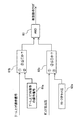
- the state determination unit 56 determines whether the operating device 20 is in the boom raising direction based on the operation signal of the operating device 20 detected by the pressure sensor 35 (operation detecting device) and the discharge pressure of the hydraulic pump 12 detected by the pressure sensor 21. It is determined whether or not the main relief valve 18 is in the relief state (steps S100 and S110). When the operating device 20 is fully operated in the boom raising direction and the main relief valve 18 is in the relief state, It is determined that the system is in the specific operation scene and the hydraulic pump 12 is in a predetermined load state, and outputs an effective operation flag (step S120).
- the state determination unit 56 includes a boom raising operation signal (command pilot pressure) of the operation device 20 detected by the pressure sensor 35 (operation detection device) and a boom raising full operation operation signal preset in the setting unit 61a. (Command pilot pressure) in the comparing section 61b to determine whether or not the boom raising operation signal is equal to or greater than the boom raising full operation signal. Further, the discharge pressure of the hydraulic pump 12 detected by the pressure sensor 21 is compared with the set pressure of the main relief valve 18 preset in the setting section 62a by the comparison section 62b, and the discharge pressure of the hydraulic pump 12 is reduced. It is determined whether the pressure is equal to or higher than the set pressure of the main relief valve 18.
- the control amount calculation unit 57 receives the valid operation flag and the torque correction amount ⁇ Ta, validates the torque correction amount ⁇ Ta, and takes in the torque correction amount ⁇ Ta *.
- This validated torque correction amount ⁇ Ta * is subjected to low-pass filter processing over an effective section in the filter processing unit 58, and a stable state amount is obtained.
- This state quantity is the feature quantity at the current time.
- a time history data generation unit 59 calculates the magnitude and change of the feature amount, adds time history information to the feature amount, generates time history data of a feature amount for engine diagnosis, and stores the time history data in the storage device 60. You.
- a torque correction amount ⁇ Ta is calculated based on a deviation ⁇ N between the engine target rotation speed and the actual rotation speed, and furthermore, the value thereof is calculated. Is filtered and calculated as a feature amount in a manner that suppresses dynamic effects, and stable calculation of the feature amount becomes possible.
- FIG. 8 is a diagram showing an example of the trend data for engine diagnosis displayed on the display screen 38b of the display device 38.
- An operator or a maintenance person or the like operates the display device 38 to display the trend data on the display screen as shown in FIG. 8, and judges the degree of deterioration of the engine 10 by observing the change over time. can do.
- the controller 37 determines whether or not the hydraulic pump 12 is in a predetermined load state, and when it is determined that the hydraulic pump 12 is in a predetermined load state,
- the control amount (for example, the torque correction value ⁇ Ta) related to the torque command value Ta of the sensing control is validated as diagnostic data of the engine 10 and can be displayed as trend data for engine diagnosis.
- the amount of data taken into the engine 10 is greatly reduced, and the cost required for operating a deterioration diagnosis such as a decrease in the output of the engine 10 can be suppressed.
- a control amount related to the torque command value Ta of the speed sensing control when the hydraulic pump 12 is in a predetermined load state an operation scene in which the load torque of the hydraulic pump 12 becomes stable. 8 to generate time history data for engine diagnosis, thereby suppressing diagnostic noise based on measurement errors and the like, as shown in FIG. Can be improved.
- the case where the number of the hydraulic pumps is one has been described.
- the loads on the hydraulic pumps are similarly calculated and summed to obtain a plurality of hydraulic pumps.
- the load state of the pump can be calculated.
- the torque correction amount ⁇ Ta since a plurality of hydraulic pumps are driven by the same engine, the state of the engine can be grasped by calculating the torque correction amount ⁇ Ta of one hydraulic pump.
- a specific operation of the hydraulic system that satisfies the “predetermined load state” of the hydraulic pump 12 for acquiring diagnostic data of the engine 10 in the state determination unit 56 that satisfies the diagnostic conditions of the engine 10 is performed. Since it is limited to the scene, the load state of the hydraulic pump 12 can be accurately grasped. Therefore, diagnosis noise can be suppressed, and the output reduction state of the engine 10 can be accurately grasped.
- the tilt amount of the hydraulic pump 12 is controlled by the controller 37, the tilt amount of the hydraulic pump 12 can be calculated in the controller 37.
- the discharge pressure of the hydraulic pump 12 is detected by the pressure sensor 21 and can be used in the controller 37. Therefore, the load state of the hydraulic pump 12 can be calculated using the pump displacement amount and the pump discharge pressure.
- T q ⁇ P / 2 ⁇ q: Tilt amount of hydraulic pump 12 (cc / rev) P: Discharge pressure of the hydraulic pump 12
- the displacement amount q and the discharge pressure P are calculated to obtain the load torque T, and the total is calculated to calculate the torque of the entire pump. can do.
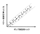
- the error state of the calculated torque is as shown in FIG.
- an error factor there is a detection error of the discharge pressure of the hydraulic pump 12 and a calculation error of the tilt amount of the hydraulic pump 12, as shown in FIG.
- the calculated load torque tends to have a certain error width. Therefore, it is effective to make a diagnosis and evaluation in a region where the pump load torque is large, in which such an error factor can be apparently reduced.
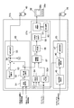
- FIG. 10 is a functional block diagram showing processing contents of the controller 37A according to the second embodiment of the present invention.
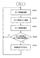
- FIG. 11A is a flowchart showing the processing contents of the pump displacement calculating section 64 and the state determining section 56A.
- step S230 It is determined whether or not the hydraulic pump 12 is present (step S230). When the pump load factor is equal to or greater than the predetermined pump load factor, it is determined that the hydraulic pump 12 is in a predetermined load state, and an effective operation flag is output (step S230). S240).
- FIG. 11B is a functional block diagram showing the processing contents of the pump displacement calculating unit 64.
- the pump displacement calculating section 64 includes a limited displacement calculating section 70 and a minimum value selecting section 71.
- the torque characteristic of the hydraulic pump 12 shown in FIG. 6 is set in the limited displacement amount calculation unit 70, and the pump displacement amount calculation unit 64 determines the torque of the speed sensing control in the limited displacement amount calculation unit 70.
- the limited pump tilt amount of the speed sensing control is calculated. That is, the limited tilting amount calculation unit 70 updates the torque characteristic of the hydraulic pump 12 so that the maximum torque decreases as the torque command value Ta decreases, and makes the torque characteristic refer to the discharge pressure of the hydraulic pump 12. Then, the limit pump tilt amount of the speed sensing control at that time is calculated.
- the minimum pumping amount calculating unit 64 in the minimum value selecting unit 71 calculates the limited pump tilting amount calculated by the limited tilting amount calculating unit 70 and the target tilt calculated by the flow control calculating unit 65 of the positive pump control. The smaller amount is selected as the current tilt amount of the hydraulic pump 12.
- the pump displacement calculating unit 64 estimates the current displacement of the hydraulic pump 12 by performing a calculation process simulating the operation of the regulator 24.
- the value measured by the position sensor may be used instead of the value calculated by the pump displacement amount calculation unit 64.
- FIG. 11C is a functional block diagram showing processing contents of the state determination unit 56A.
- FIG. 11C shows a case where there are two hydraulic pumps.
- the state determination unit 56A includes torque calculation units 72a and 72b, an addition unit 73, a pump load ratio calculation unit 74, a pump load ratio reference value setting unit 75, and a comparison unit 76.
- the state determination unit 56A uses the above-described equation in the torque calculation unit 72a, using the displacement amount of the hydraulic pump 12 calculated by the pump displacement amount calculation unit 64 and the discharge pressure of the hydraulic pump 12 detected by the pressure sensor 21. , The load torque of the hydraulic pump 12 is calculated. Similarly, the torque calculation unit 72b calculates the load torque of a hydraulic pump (not shown). Next, the adding unit 73 calculates the total load torque of the two hydraulic pumps by adding the load torques. Next, the state determination unit 56A calculates the pump load ratio by dividing the total load torque of the two hydraulic pumps by the maximum pump torque Tmax of the hydraulic pump 12 in the pump load ratio calculation unit 74.
- the engine diagnosis calculation unit 67A calculates the characteristic amount based on the valid operation flag in the same manner as in the first embodiment, so that trend data for engine diagnosis can be displayed on the display device 38.
- the load factor is 70% or less, the condition is not satisfied, so that a new feature value is not calculated, and the previous value is held.
- the load factor is 70% or more, the valid operation flag becomes a true value, and the following calculation is performed as in the first embodiment.
- the effective operation flag and the torque correction amount ⁇ Ta are input, the torque correction amount ⁇ Ta is validated, the torque correction amount ⁇ Ta * is fetched, and the filter processing section 58 converts the torque correction amount ⁇ Ta * into the torque correction amount ⁇ Ta *.
- a low-pass filter process is performed on the low-pass filter to obtain a feature value at the current time.
- the time history data generation unit 59 calculates the magnitude and change of the feature amount and adds time history information to generate time history data of the engine diagnosis feature amount, and stores it in the storage device 60.
- the display calculation unit 61 reads out time history data of the feature amount for a predetermined period stored in the storage device 60, and uses the time history data as trend data for engine diagnosis to the display device 38. Display.
- the pump load factor reference value is set to 70%. However, if it is desired to secure and evaluate more operation scenes for acquiring diagnostic data, the load factor may be further reduced.
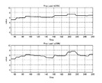
- FIGS. 12 and 13 show examples of feature amount trend data when the load factor reference values are different. 12 and 13 show the case where the load factor reference value is 70% and the case where the load factor reference value is 50%. FIG. 12 shows a case where the change in the feature amount is relatively small, and FIG. Is shown.
- the case where the load factor reference value of each of FIGS. 12 and 13 is 70% and the case where the load factor reference value is 50%
- the case where the load factor reference value is 50% is the case where the load factor reference value is 70%. Since more features are used than before, it is possible to evaluate more detailed changes. However, as described above, the load factor is small, so errors and the like enter, and as a result, the influence of noise is reduced. Easier to receive. Therefore, it is desirable to set the pump load factor reference value in consideration of the balance between the number of feature amount data to be used and the effect of noise.
- the load factor reference value can be arbitrarily changed from the outside so that the load factor reference value can be set according to the situation.
- FIG. 11C also shows such a modification. That is, a load factor indicating device 77 is provided as shown by a dashed line in FIG. 11B, and the operator can operate the load factor indicating device 77 to adjust the load factor reference value of the pump load factor reference value setting unit. .
- a plurality of load factor reference values may be set, and a feature amount may be calculated to display trend data. Good.
- the control amount calculation unit 57, the filter processing unit 58, the time history data generation unit 59, the storage device 60, and the display calculation unit 61 calculate the respective feature amounts in response to the first and second valid operation flags. , So that trend data can be displayed.
- FIG. 14 is a diagram showing an example of engine diagnosis trend data displayed on the display screen 38b of the display device 38 in such a modification.
- two types of trend data reflecting the variation tendency of the feature amount are displayed on the display screen 38b, and these two types of trend data can be simultaneously checked.
- a confirmer such as an operator or a maintenance person can simultaneously confirm diagnostic data based on a plurality of load factor reference values, make a decision while confirming progress, and grasp a stable result.
Landscapes
- Engineering & Computer Science (AREA)
- General Engineering & Computer Science (AREA)
- Structural Engineering (AREA)
- Mining & Mineral Resources (AREA)
- Civil Engineering (AREA)
- Mechanical Engineering (AREA)
- Chemical & Material Sciences (AREA)
- Combustion & Propulsion (AREA)
- Physics & Mathematics (AREA)
- Fluid Mechanics (AREA)
- General Physics & Mathematics (AREA)
- Operation Control Of Excavators (AREA)
- Control Of Vehicle Engines Or Engines For Specific Uses (AREA)
- Combined Controls Of Internal Combustion Engines (AREA)
- Control Of Positive-Displacement Pumps (AREA)
Priority Applications (4)
| Application Number | Priority Date | Filing Date | Title |
|---|---|---|---|
| US17/264,324 US12152374B2 (en) | 2018-09-26 | 2019-04-18 | Construction machine |
| CN201980044285.XA CN112368452B (zh) | 2018-09-26 | 2019-04-18 | 工程机械 |
| EP19865047.5A EP3859091B1 (en) | 2018-09-26 | 2019-04-18 | Construction machine |
| KR1020207038014A KR102490904B1 (ko) | 2018-09-26 | 2019-04-18 | 건설 기계 |
Applications Claiming Priority (2)
| Application Number | Priority Date | Filing Date | Title |
|---|---|---|---|
| JP2018181055A JP7114429B2 (ja) | 2018-09-26 | 2018-09-26 | 建設機械 |
| JP2018-181055 | 2018-09-26 |
Publications (1)
| Publication Number | Publication Date |
|---|---|
| WO2020066098A1 true WO2020066098A1 (ja) | 2020-04-02 |
Family
ID=69953030
Family Applications (1)
| Application Number | Title | Priority Date | Filing Date |
|---|---|---|---|
| PCT/JP2019/016724 Ceased WO2020066098A1 (ja) | 2018-09-26 | 2019-04-18 | 建設機械 |
Country Status (6)
| Country | Link |
|---|---|
| US (1) | US12152374B2 (https=) |
| EP (1) | EP3859091B1 (https=) |
| JP (1) | JP7114429B2 (https=) |
| KR (1) | KR102490904B1 (https=) |
| CN (1) | CN112368452B (https=) |
| WO (1) | WO2020066098A1 (https=) |
Cited By (1)
| Publication number | Priority date | Publication date | Assignee | Title |
|---|---|---|---|---|
| CN115324148A (zh) * | 2022-08-17 | 2022-11-11 | 三一重机有限公司 | 电动工程机械的故障保护控制方法、装置及电动工程机械 |
Families Citing this family (7)
| Publication number | Priority date | Publication date | Assignee | Title |
|---|---|---|---|---|
| JP7151618B2 (ja) * | 2019-05-14 | 2022-10-12 | トヨタ自動車株式会社 | 車両 |
| JP7368130B2 (ja) * | 2019-07-19 | 2023-10-24 | 株式会社小松製作所 | 作業機械および作業機械の制御方法 |
| JP7514163B2 (ja) * | 2020-10-22 | 2024-07-10 | 日立建機株式会社 | 建設機械のエンジン診断装置 |
| JP7009600B1 (ja) * | 2020-12-07 | 2022-01-25 | 日立建機株式会社 | 作業機械 |
| CN113062806B (zh) * | 2021-03-08 | 2023-06-02 | 河北华北柴油机有限责任公司 | 一种基于emr系统的泵组调速控制方法 |
| CN117836518A (zh) * | 2021-12-13 | 2024-04-05 | 日立建机株式会社 | 泵的诊断装置及工程机械 |
| JP7742141B2 (ja) * | 2022-04-26 | 2025-09-19 | 株式会社岩崎 | 情報通知システム |
Citations (6)
| Publication number | Priority date | Publication date | Assignee | Title |
|---|---|---|---|---|
| JPH11101183A (ja) * | 1997-09-29 | 1999-04-13 | Hitachi Constr Mach Co Ltd | 油圧建設機械の油圧ポンプのトルク制御装置 |
| JP2000073812A (ja) * | 1998-09-03 | 2000-03-07 | Hitachi Constr Mach Co Ltd | 油圧建設機械の油圧ポンプのトルク制御装置 |
| JP2000073960A (ja) * | 1998-09-03 | 2000-03-07 | Hitachi Constr Mach Co Ltd | 油圧建設機械の油圧ポンプのトルク制御装置 |
| JP2005180259A (ja) * | 2003-12-18 | 2005-07-07 | Hitachi Constr Mach Co Ltd | 油圧建設機械の制御装置 |
| JP2005226493A (ja) * | 2004-02-10 | 2005-08-25 | Hitachi Constr Mach Co Ltd | 建設機械のエンジン管理装置 |
| JP4853921B2 (ja) | 2007-02-14 | 2012-01-11 | キャタピラー エス エー アール エル | 機体診断システム |
Family Cites Families (13)
| Publication number | Priority date | Publication date | Assignee | Title |
|---|---|---|---|---|
| JPH02115582A (ja) * | 1988-10-25 | 1990-04-27 | Hitachi Constr Mach Co Ltd | 可変容量油圧ポンプの入力トルク制御装置 |
| JPH07119183A (ja) * | 1993-10-21 | 1995-05-09 | Hitachi Constr Mach Co Ltd | 油圧作業機のモニタ装置 |
| JP4322499B2 (ja) * | 2002-12-11 | 2009-09-02 | 日立建機株式会社 | 油圧建設機械のポンプトルク制御方法及び装置 |
| JP4342848B2 (ja) * | 2003-06-19 | 2009-10-14 | 日立建機株式会社 | 作業機の油圧駆動装置 |
| JP2005180226A (ja) | 2003-12-17 | 2005-07-07 | Hitachi Constr Mach Co Ltd | 建設機械のエンジン給気系異常検出装置及び異常検出方法 |
| JP4413122B2 (ja) * | 2004-10-13 | 2010-02-10 | 日立建機株式会社 | 油圧建設機械の制御装置 |
| CN101761105B (zh) * | 2009-11-19 | 2011-08-17 | 龙工(上海)机械制造有限公司 | 一种液压挖掘机的功率匹配方法 |
| JP5383537B2 (ja) * | 2010-02-03 | 2014-01-08 | 日立建機株式会社 | 油圧システムのポンプ制御装置 |
| JP5341134B2 (ja) * | 2011-05-25 | 2013-11-13 | 日立建機株式会社 | 油圧作業機械 |
| US9568030B2 (en) * | 2014-03-24 | 2017-02-14 | Caterpillar Inc. | System and method for managing machine power system |
| CN104652523B (zh) * | 2014-12-17 | 2018-02-16 | 徐工集团工程机械股份有限公司科技分公司 | 一种装载机电液复合控制液压系统及其控制方法 |
| JP2016169818A (ja) * | 2015-03-13 | 2016-09-23 | 川崎重工業株式会社 | 油圧駆動システム |
| JP6531225B2 (ja) * | 2016-09-16 | 2019-06-12 | 株式会社日立建機ティエラ | ハイブリッド式作業機械 |
-
2018
- 2018-09-26 JP JP2018181055A patent/JP7114429B2/ja active Active
-
2019
- 2019-04-18 KR KR1020207038014A patent/KR102490904B1/ko active Active
- 2019-04-18 WO PCT/JP2019/016724 patent/WO2020066098A1/ja not_active Ceased
- 2019-04-18 CN CN201980044285.XA patent/CN112368452B/zh active Active
- 2019-04-18 EP EP19865047.5A patent/EP3859091B1/en active Active
- 2019-04-18 US US17/264,324 patent/US12152374B2/en active Active
Patent Citations (6)
| Publication number | Priority date | Publication date | Assignee | Title |
|---|---|---|---|---|
| JPH11101183A (ja) * | 1997-09-29 | 1999-04-13 | Hitachi Constr Mach Co Ltd | 油圧建設機械の油圧ポンプのトルク制御装置 |
| JP2000073812A (ja) * | 1998-09-03 | 2000-03-07 | Hitachi Constr Mach Co Ltd | 油圧建設機械の油圧ポンプのトルク制御装置 |
| JP2000073960A (ja) * | 1998-09-03 | 2000-03-07 | Hitachi Constr Mach Co Ltd | 油圧建設機械の油圧ポンプのトルク制御装置 |
| JP2005180259A (ja) * | 2003-12-18 | 2005-07-07 | Hitachi Constr Mach Co Ltd | 油圧建設機械の制御装置 |
| JP2005226493A (ja) * | 2004-02-10 | 2005-08-25 | Hitachi Constr Mach Co Ltd | 建設機械のエンジン管理装置 |
| JP4853921B2 (ja) | 2007-02-14 | 2012-01-11 | キャタピラー エス エー アール エル | 機体診断システム |
Non-Patent Citations (1)
| Title |
|---|
| See also references of EP3859091A4 |
Cited By (1)
| Publication number | Priority date | Publication date | Assignee | Title |
|---|---|---|---|---|
| CN115324148A (zh) * | 2022-08-17 | 2022-11-11 | 三一重机有限公司 | 电动工程机械的故障保护控制方法、装置及电动工程机械 |
Also Published As
| Publication number | Publication date |
|---|---|
| JP7114429B2 (ja) | 2022-08-08 |
| US20210301502A1 (en) | 2021-09-30 |
| EP3859091A1 (en) | 2021-08-04 |
| CN112368452B (zh) | 2022-07-12 |
| EP3859091A4 (en) | 2022-06-22 |
| CN112368452A (zh) | 2021-02-12 |
| KR102490904B1 (ko) | 2023-01-27 |
| US12152374B2 (en) | 2024-11-26 |
| EP3859091B1 (en) | 2026-03-25 |
| KR20210014701A (ko) | 2021-02-09 |
| JP2020051110A (ja) | 2020-04-02 |
Similar Documents
| Publication | Publication Date | Title |
|---|---|---|
| JP7114429B2 (ja) | 建設機械 | |
| JP7058783B2 (ja) | 電動式油圧作業機械の油圧駆動装置 | |
| US8793023B2 (en) | Method of controlling an electro-hydraulic actuator system having multiple actuators | |
| US8321114B2 (en) | Work vehicle and work vehicle control method | |
| EP3779210B1 (en) | Construction machine | |
| JP5957628B1 (ja) | 作業機械の機関制御装置、作業機械及び作業機械の機関制御方法 | |
| KR101770488B1 (ko) | 건설 기계 | |
| JP5322215B2 (ja) | 作業機械における制御システム | |
| KR20150105916A (ko) | 작업 기계의 유압 구동 장치 | |
| JP6587247B2 (ja) | 作業機械の制御装置および制御方法 | |
| JP5265595B2 (ja) | ハイブリッド建設機械の制御装置 | |
| US12018460B2 (en) | Excavator | |
| KR20030010894A (ko) | 굴삭기의 엔진과 펌프의 출력 자동 제어 시스템 | |
| JP2004169589A (ja) | 作業機械のエンジン制御システム | |
| JP2015135031A (ja) | 走行式油圧作業機械 | |
| KR960004630B1 (ko) | 유압기계의 출력제어장치 | |
| JP6901441B2 (ja) | 油圧駆動装置 | |
| JPWO2018163826A1 (ja) | 建設機械 | |
| JP2025133647A (ja) | 作業機械 | |
| JP2001124004A (ja) | 建設機械の油圧制御装置 |
Legal Events
| Date | Code | Title | Description |
|---|---|---|---|
| 121 | Ep: the epo has been informed by wipo that ep was designated in this application |
Ref document number: 19865047 Country of ref document: EP Kind code of ref document: A1 |
|
| ENP | Entry into the national phase |
Ref document number: 20207038014 Country of ref document: KR Kind code of ref document: A |
|
| NENP | Non-entry into the national phase |
Ref country code: DE |
|
| ENP | Entry into the national phase |
Ref document number: 2019865047 Country of ref document: EP Effective date: 20210426 |
|
| WWG | Wipo information: grant in national office |
Ref document number: 2019865047 Country of ref document: EP |