WO2020066098A1 - Construction machine - Google Patents
Construction machine Download PDFInfo
- Publication number
- WO2020066098A1 WO2020066098A1 PCT/JP2019/016724 JP2019016724W WO2020066098A1 WO 2020066098 A1 WO2020066098 A1 WO 2020066098A1 JP 2019016724 W JP2019016724 W JP 2019016724W WO 2020066098 A1 WO2020066098 A1 WO 2020066098A1
- Authority
- WO
- WIPO (PCT)
- Prior art keywords
- pump
- engine
- hydraulic pump
- torque
- hydraulic
- Prior art date
Links
Images


Classifications
-
- E—FIXED CONSTRUCTIONS
- E02—HYDRAULIC ENGINEERING; FOUNDATIONS; SOIL SHIFTING
- E02F—DREDGING; SOIL-SHIFTING
- E02F9/00—Component parts of dredgers or soil-shifting machines, not restricted to one of the kinds covered by groups E02F3/00 - E02F7/00
- E02F9/26—Indicating devices
-
- F—MECHANICAL ENGINEERING; LIGHTING; HEATING; WEAPONS; BLASTING
- F02—COMBUSTION ENGINES; HOT-GAS OR COMBUSTION-PRODUCT ENGINE PLANTS
- F02D—CONTROLLING COMBUSTION ENGINES
- F02D41/00—Electrical control of supply of combustible mixture or its constituents
- F02D41/22—Safety or indicating devices for abnormal conditions
-
- E—FIXED CONSTRUCTIONS
- E02—HYDRAULIC ENGINEERING; FOUNDATIONS; SOIL SHIFTING
- E02F—DREDGING; SOIL-SHIFTING
- E02F9/00—Component parts of dredgers or soil-shifting machines, not restricted to one of the kinds covered by groups E02F3/00 - E02F7/00
- E02F9/20—Drives; Control devices
- E02F9/2004—Control mechanisms, e.g. control levers
-
- E—FIXED CONSTRUCTIONS
- E02—HYDRAULIC ENGINEERING; FOUNDATIONS; SOIL SHIFTING
- E02F—DREDGING; SOIL-SHIFTING
- E02F9/00—Component parts of dredgers or soil-shifting machines, not restricted to one of the kinds covered by groups E02F3/00 - E02F7/00
- E02F9/20—Drives; Control devices
- E02F9/2058—Electric or electro-mechanical or mechanical control devices of vehicle sub-units
- E02F9/2062—Control of propulsion units
- E02F9/2066—Control of propulsion units of the type combustion engines
-
- E—FIXED CONSTRUCTIONS
- E02—HYDRAULIC ENGINEERING; FOUNDATIONS; SOIL SHIFTING
- E02F—DREDGING; SOIL-SHIFTING
- E02F9/00—Component parts of dredgers or soil-shifting machines, not restricted to one of the kinds covered by groups E02F3/00 - E02F7/00
- E02F9/20—Drives; Control devices
- E02F9/22—Hydraulic or pneumatic drives
- E02F9/2221—Control of flow rate; Load sensing arrangements
- E02F9/2232—Control of flow rate; Load sensing arrangements using one or more variable displacement pumps
- E02F9/2235—Control of flow rate; Load sensing arrangements using one or more variable displacement pumps including an electronic controller
-
- E—FIXED CONSTRUCTIONS
- E02—HYDRAULIC ENGINEERING; FOUNDATIONS; SOIL SHIFTING
- E02F—DREDGING; SOIL-SHIFTING
- E02F9/00—Component parts of dredgers or soil-shifting machines, not restricted to one of the kinds covered by groups E02F3/00 - E02F7/00
- E02F9/20—Drives; Control devices
- E02F9/22—Hydraulic or pneumatic drives
- E02F9/2246—Control of prime movers, e.g. depending on the hydraulic load of work tools
-
- E—FIXED CONSTRUCTIONS
- E02—HYDRAULIC ENGINEERING; FOUNDATIONS; SOIL SHIFTING
- E02F—DREDGING; SOIL-SHIFTING
- E02F9/00—Component parts of dredgers or soil-shifting machines, not restricted to one of the kinds covered by groups E02F3/00 - E02F7/00
- E02F9/20—Drives; Control devices
- E02F9/22—Hydraulic or pneumatic drives
- E02F9/226—Safety arrangements, e.g. hydraulic driven fans, preventing cavitation, leakage, overheating
-
- E—FIXED CONSTRUCTIONS
- E02—HYDRAULIC ENGINEERING; FOUNDATIONS; SOIL SHIFTING
- E02F—DREDGING; SOIL-SHIFTING
- E02F9/00—Component parts of dredgers or soil-shifting machines, not restricted to one of the kinds covered by groups E02F3/00 - E02F7/00
- E02F9/26—Indicating devices
- E02F9/267—Diagnosing or detecting failure of vehicles
-
- F—MECHANICAL ENGINEERING; LIGHTING; HEATING; WEAPONS; BLASTING
- F02—COMBUSTION ENGINES; HOT-GAS OR COMBUSTION-PRODUCT ENGINE PLANTS
- F02B—INTERNAL-COMBUSTION PISTON ENGINES; COMBUSTION ENGINES IN GENERAL
- F02B63/00—Adaptations of engines for driving pumps, hand-held tools or electric generators; Portable combinations of engines with engine-driven devices
- F02B63/06—Adaptations of engines for driving pumps, hand-held tools or electric generators; Portable combinations of engines with engine-driven devices for pumps
-
- F—MECHANICAL ENGINEERING; LIGHTING; HEATING; WEAPONS; BLASTING
- F02—COMBUSTION ENGINES; HOT-GAS OR COMBUSTION-PRODUCT ENGINE PLANTS
- F02D—CONTROLLING COMBUSTION ENGINES
- F02D29/00—Controlling engines, such controlling being peculiar to the devices driven thereby, the devices being other than parts or accessories essential to engine operation, e.g. controlling of engines by signals external thereto
- F02D29/02—Controlling engines, such controlling being peculiar to the devices driven thereby, the devices being other than parts or accessories essential to engine operation, e.g. controlling of engines by signals external thereto peculiar to engines driving vehicles; peculiar to engines driving variable pitch propellers
-
- F—MECHANICAL ENGINEERING; LIGHTING; HEATING; WEAPONS; BLASTING
- F02—COMBUSTION ENGINES; HOT-GAS OR COMBUSTION-PRODUCT ENGINE PLANTS
- F02D—CONTROLLING COMBUSTION ENGINES
- F02D29/00—Controlling engines, such controlling being peculiar to the devices driven thereby, the devices being other than parts or accessories essential to engine operation, e.g. controlling of engines by signals external thereto
- F02D29/04—Controlling engines, such controlling being peculiar to the devices driven thereby, the devices being other than parts or accessories essential to engine operation, e.g. controlling of engines by signals external thereto peculiar to engines driving pumps
-
- F—MECHANICAL ENGINEERING; LIGHTING; HEATING; WEAPONS; BLASTING
- F02—COMBUSTION ENGINES; HOT-GAS OR COMBUSTION-PRODUCT ENGINE PLANTS
- F02D—CONTROLLING COMBUSTION ENGINES
- F02D31/00—Use of speed-sensing governors to control combustion engines, not otherwise provided for
- F02D31/001—Electric control of rotation speed
-
- F—MECHANICAL ENGINEERING; LIGHTING; HEATING; WEAPONS; BLASTING
- F02—COMBUSTION ENGINES; HOT-GAS OR COMBUSTION-PRODUCT ENGINE PLANTS
- F02D—CONTROLLING COMBUSTION ENGINES
- F02D41/00—Electrical control of supply of combustible mixture or its constituents
- F02D41/02—Circuit arrangements for generating control signals
- F02D41/14—Introducing closed-loop corrections
- F02D41/1497—With detection of the mechanical response of the engine
-
- F—MECHANICAL ENGINEERING; LIGHTING; HEATING; WEAPONS; BLASTING
- F04—POSITIVE - DISPLACEMENT MACHINES FOR LIQUIDS; PUMPS FOR LIQUIDS OR ELASTIC FLUIDS
- F04B—POSITIVE-DISPLACEMENT MACHINES FOR LIQUIDS; PUMPS
- F04B49/00—Control, e.g. of pump delivery, or pump pressure of, or safety measures for, machines, pumps, or pumping installations, not otherwise provided for, or of interest apart from, groups F04B1/00 - F04B47/00
- F04B49/12—Control, e.g. of pump delivery, or pump pressure of, or safety measures for, machines, pumps, or pumping installations, not otherwise provided for, or of interest apart from, groups F04B1/00 - F04B47/00 by varying the length of stroke of the working members
-
- F—MECHANICAL ENGINEERING; LIGHTING; HEATING; WEAPONS; BLASTING
- F15—FLUID-PRESSURE ACTUATORS; HYDRAULICS OR PNEUMATICS IN GENERAL
- F15B—SYSTEMS ACTING BY MEANS OF FLUIDS IN GENERAL; FLUID-PRESSURE ACTUATORS, e.g. SERVOMOTORS; DETAILS OF FLUID-PRESSURE SYSTEMS, NOT OTHERWISE PROVIDED FOR
- F15B15/00—Fluid-actuated devices for displacing a member from one position to another; Gearing associated therewith
- F15B15/18—Combined units comprising both motor and pump
-
- G—PHYSICS
- G07—CHECKING-DEVICES
- G07C—TIME OR ATTENDANCE REGISTERS; REGISTERING OR INDICATING THE WORKING OF MACHINES; GENERATING RANDOM NUMBERS; VOTING OR LOTTERY APPARATUS; ARRANGEMENTS, SYSTEMS OR APPARATUS FOR CHECKING NOT PROVIDED FOR ELSEWHERE
- G07C5/00—Registering or indicating the working of vehicles
- G07C5/08—Registering or indicating performance data other than driving, working, idle, or waiting time, with or without registering driving, working, idle or waiting time
- G07C5/0808—Diagnosing performance data
-
- G—PHYSICS
- G07—CHECKING-DEVICES
- G07C—TIME OR ATTENDANCE REGISTERS; REGISTERING OR INDICATING THE WORKING OF MACHINES; GENERATING RANDOM NUMBERS; VOTING OR LOTTERY APPARATUS; ARRANGEMENTS, SYSTEMS OR APPARATUS FOR CHECKING NOT PROVIDED FOR ELSEWHERE
- G07C5/00—Registering or indicating the working of vehicles
- G07C5/08—Registering or indicating performance data other than driving, working, idle, or waiting time, with or without registering driving, working, idle or waiting time
- G07C5/0816—Indicating performance data, e.g. occurrence of a malfunction
- G07C5/0825—Indicating performance data, e.g. occurrence of a malfunction using optical means
-
- E—FIXED CONSTRUCTIONS
- E02—HYDRAULIC ENGINEERING; FOUNDATIONS; SOIL SHIFTING
- E02F—DREDGING; SOIL-SHIFTING
- E02F3/00—Dredgers; Soil-shifting machines
- E02F3/04—Dredgers; Soil-shifting machines mechanically-driven
- E02F3/28—Dredgers; Soil-shifting machines mechanically-driven with digging tools mounted on a dipper- or bucket-arm, i.e. there is either one arm or a pair of arms, e.g. dippers, buckets
- E02F3/30—Dredgers; Soil-shifting machines mechanically-driven with digging tools mounted on a dipper- or bucket-arm, i.e. there is either one arm or a pair of arms, e.g. dippers, buckets with a dipper-arm pivoted on a cantilever beam, i.e. boom
- E02F3/32—Dredgers; Soil-shifting machines mechanically-driven with digging tools mounted on a dipper- or bucket-arm, i.e. there is either one arm or a pair of arms, e.g. dippers, buckets with a dipper-arm pivoted on a cantilever beam, i.e. boom working downwardly and towards the machine, e.g. with backhoes
-
- E—FIXED CONSTRUCTIONS
- E02—HYDRAULIC ENGINEERING; FOUNDATIONS; SOIL SHIFTING
- E02F—DREDGING; SOIL-SHIFTING
- E02F3/00—Dredgers; Soil-shifting machines
- E02F3/04—Dredgers; Soil-shifting machines mechanically-driven
- E02F3/28—Dredgers; Soil-shifting machines mechanically-driven with digging tools mounted on a dipper- or bucket-arm, i.e. there is either one arm or a pair of arms, e.g. dippers, buckets
- E02F3/36—Component parts
- E02F3/42—Drives for dippers, buckets, dipper-arms or bucket-arms
- E02F3/425—Drive systems for dipper-arms, backhoes or the like
-
- E—FIXED CONSTRUCTIONS
- E02—HYDRAULIC ENGINEERING; FOUNDATIONS; SOIL SHIFTING
- E02F—DREDGING; SOIL-SHIFTING
- E02F9/00—Component parts of dredgers or soil-shifting machines, not restricted to one of the kinds covered by groups E02F3/00 - E02F7/00
- E02F9/20—Drives; Control devices
- E02F9/22—Hydraulic or pneumatic drives
- E02F9/2264—Arrangements or adaptations of elements for hydraulic drives
- E02F9/2267—Valves or distributors
-
- E—FIXED CONSTRUCTIONS
- E02—HYDRAULIC ENGINEERING; FOUNDATIONS; SOIL SHIFTING
- E02F—DREDGING; SOIL-SHIFTING
- E02F9/00—Component parts of dredgers or soil-shifting machines, not restricted to one of the kinds covered by groups E02F3/00 - E02F7/00
- E02F9/20—Drives; Control devices
- E02F9/22—Hydraulic or pneumatic drives
- E02F9/2264—Arrangements or adaptations of elements for hydraulic drives
- E02F9/2271—Actuators and supports therefor and protection therefor
-
- E—FIXED CONSTRUCTIONS
- E02—HYDRAULIC ENGINEERING; FOUNDATIONS; SOIL SHIFTING
- E02F—DREDGING; SOIL-SHIFTING
- E02F9/00—Component parts of dredgers or soil-shifting machines, not restricted to one of the kinds covered by groups E02F3/00 - E02F7/00
- E02F9/20—Drives; Control devices
- E02F9/22—Hydraulic or pneumatic drives
- E02F9/2278—Hydraulic circuits
- E02F9/2285—Pilot-operated systems
-
- E—FIXED CONSTRUCTIONS
- E02—HYDRAULIC ENGINEERING; FOUNDATIONS; SOIL SHIFTING
- E02F—DREDGING; SOIL-SHIFTING
- E02F9/00—Component parts of dredgers or soil-shifting machines, not restricted to one of the kinds covered by groups E02F3/00 - E02F7/00
- E02F9/20—Drives; Control devices
- E02F9/22—Hydraulic or pneumatic drives
- E02F9/2278—Hydraulic circuits
- E02F9/2296—Systems with a variable displacement pump
-
- F—MECHANICAL ENGINEERING; LIGHTING; HEATING; WEAPONS; BLASTING
- F02—COMBUSTION ENGINES; HOT-GAS OR COMBUSTION-PRODUCT ENGINE PLANTS
- F02D—CONTROLLING COMBUSTION ENGINES
- F02D41/00—Electrical control of supply of combustible mixture or its constituents
- F02D41/02—Circuit arrangements for generating control signals
- F02D41/14—Introducing closed-loop corrections
- F02D41/1401—Introducing closed-loop corrections characterised by the control or regulation method
- F02D2041/1413—Controller structures or design
- F02D2041/1432—Controller structures or design the system including a filter, e.g. a low pass or high pass filter
-
- F—MECHANICAL ENGINEERING; LIGHTING; HEATING; WEAPONS; BLASTING
- F02—COMBUSTION ENGINES; HOT-GAS OR COMBUSTION-PRODUCT ENGINE PLANTS
- F02D—CONTROLLING COMBUSTION ENGINES
- F02D41/00—Electrical control of supply of combustible mixture or its constituents
- F02D41/22—Safety or indicating devices for abnormal conditions
- F02D2041/228—Warning displays
-
- F—MECHANICAL ENGINEERING; LIGHTING; HEATING; WEAPONS; BLASTING
- F02—COMBUSTION ENGINES; HOT-GAS OR COMBUSTION-PRODUCT ENGINE PLANTS
- F02D—CONTROLLING COMBUSTION ENGINES
- F02D2200/00—Input parameters for engine control
- F02D2200/02—Input parameters for engine control the parameters being related to the engine
- F02D2200/10—Parameters related to the engine output, e.g. engine torque or engine speed
- F02D2200/1006—Engine torque losses, e.g. friction or pumping losses or losses caused by external loads of accessories
-
- F—MECHANICAL ENGINEERING; LIGHTING; HEATING; WEAPONS; BLASTING
- F02—COMBUSTION ENGINES; HOT-GAS OR COMBUSTION-PRODUCT ENGINE PLANTS
- F02D—CONTROLLING COMBUSTION ENGINES
- F02D2200/00—Input parameters for engine control
- F02D2200/02—Input parameters for engine control the parameters being related to the engine
- F02D2200/10—Parameters related to the engine output, e.g. engine torque or engine speed
- F02D2200/101—Engine speed
-
- F—MECHANICAL ENGINEERING; LIGHTING; HEATING; WEAPONS; BLASTING
- F02—COMBUSTION ENGINES; HOT-GAS OR COMBUSTION-PRODUCT ENGINE PLANTS
- F02D—CONTROLLING COMBUSTION ENGINES
- F02D2250/00—Engine control related to specific problems or objectives
- F02D2250/18—Control of the engine output torque
-
- F—MECHANICAL ENGINEERING; LIGHTING; HEATING; WEAPONS; BLASTING
- F02—COMBUSTION ENGINES; HOT-GAS OR COMBUSTION-PRODUCT ENGINE PLANTS
- F02D—CONTROLLING COMBUSTION ENGINES
- F02D41/00—Electrical control of supply of combustible mixture or its constituents
- F02D41/02—Circuit arrangements for generating control signals
- F02D41/021—Introducing corrections for particular conditions exterior to the engine
Definitions
- the present invention relates to a construction machine such as a hydraulic shovel or a crane provided with an engine diagnosis device.
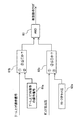
- frequency distribution information indicating the relationship between the magnitude of a signal related to an engine output and the frequency of occurrence is collected by a vehicle body management controller at regular intervals of operation, and the data is stored in a storage server by a wireless communication function. Send to and store the data. Then, by comparing the stored plurality of pieces of frequency distribution information in a time series and comparing them, a decrease in engine output is detected, and a decrease in engine output is determined.
- the magnitude of the engine output and its frequency information are collected and accumulated over a period of time, and compared in a time-series manner.
- the degree of deterioration of the engine can be determined based on the degree of change in the feature amount of a single unit.
- the difference in output is strictly affected by the difference in work load.
- long-term work contents may be different at work sites and the like, and it is expected that the work load naturally differs.
- the engine output tendency is affected by the site and does not purely reflect the engine performance, and may be somewhat evaluated as a statistical tendency, but the characteristics for judgment It is considered that the quantity includes a large uncertainty (error).
- the present invention has been made in view of such a situation, and provides a construction machine capable of improving the accuracy of diagnosis of engine deterioration while suppressing the cost required for operation of deterioration diagnosis such as engine output reduction. With the goal.
- the present invention provides an engine, a variable displacement hydraulic pump driven by the engine, a hydraulic actuator driven by the discharge oil of the hydraulic pump, A hydraulic system comprising a regulator for controlling the displacement of the hydraulic pump so as not to exceed the absorption torque; and a maximum absorption torque of the hydraulic pump as the load torque of the hydraulic pump increases and the engine speed decreases.
- a construction machine including a controller that calculates a torque command value of speed sensing control for controlling the regulator so that the regulator is reduced, and an engine diagnostic device that diagnoses the engine, the engine diagnostic device is controlled by the controller.
- the controller comprises the hydraulic pump It is determined whether or not the engine is in a predetermined load state for acquiring diagnostic data of the engine, and when it is determined that the hydraulic pump is in the predetermined load state, a torque command value of the speed sensing control is determined.
- the related control amount is validated as diagnostic data of the engine, time history data is generated using the validated control amount as a current feature amount, and the time history data is displayed as trend data for engine diagnosis on a display device. It shall be possible.
- the present invention it is possible to improve the diagnosis accuracy of engine deterioration while suppressing the cost required for operating deterioration diagnosis such as engine output reduction.
- FIG. 11 is a diagram illustrating an example of trend data for engine diagnosis displayed on a display screen of a display device according to a modification.
- the hydraulic excavator includes a traveling body 101, a revolving body 102 disposed on the traveling body 101, and a front working machine attached to the revolving body 102, that is, a working device 103.
- the traveling body 101 has a pair of right and left crawlers 101a and 101b (only one side is shown in FIG. 1), and the crawlers 101a and 101b are driven by traveling motors 110a and 110b (only one side is shown) to travel.
- the swing body 102 is driven by a swing motor 102a, and swings on the traveling body 101.
- the working device 103 includes a boom 104 that is rotatably attached to the revolving body 102 in the vertical direction, an arm 105 that is rotatably attached to the boom 104, and a bucket 106 that is rotatably attached to the arm 105. It is configured.
- the boom 104 is driven by a boom cylinder 112
- the arm 105 is driven by an arm cylinder 113
- the bucket 106 is driven by a bucket cylinder 114.
- a cabin 120 constituting a cab is provided at a front position on the revolving superstructure 102.
- FIG. 2 shows a hydraulic system mounted on the hydraulic excavator according to the first embodiment of the present invention and a control system thereof. It is a figure showing the whole composition including.
- the hydraulic system mounted on the hydraulic excavator includes a diesel engine 10 (hereinafter simply referred to as an engine) as a prime mover, a variable displacement hydraulic pump 12 driven by the engine 10, and a plurality of hydraulic actuators 14 (in FIG. And a control valve 16 having a plurality of control spools for controlling the flow of pressure oil supplied to the hydraulic pump 12 and a pressure supplied from the hydraulic pump 12 to the control valve 16.
- a main relief valve 18 that regulates the upper limit of (discharge pressure of the hydraulic pump 12), and a plurality of hydraulic pilot-type operating devices that generate a command pilot pressure (operation signal) for switching a plurality of control spools built in the control valve 16. 20 (only one is shown in FIG.
- a shuttle valve block 22 containing a plurality of shuttle valves for selecting the highest command pilot pressure from among the command pilot pressures guided to the valve 16 and generating a pump flow control pressure, and a tilting amount (displacement, That is, a regulator 24 that controls the discharge capacity of the hydraulic pump 12 is controlled.
- the control system includes a rotary dial-type target rotation speed indicating device 32 that generates an instruction signal of a target rotation speed of the engine 10 by an operator's rotation operation, and an engine rotation sensor 33 that detects the rotation speed (actual rotation speed) of the engine 10.
- a pressure sensor 21 for detecting the discharge pressure of the hydraulic pump 12
- a plurality of pressure sensors 35 as operation detection devices for detecting a command pilot pressure (operation signal) generated by the plurality of operation devices 20 (for convenience in FIG. 2, Only one is shown
- a pressure sensor 36 for detecting the pump flow rate control pressure generated by the shuttle valve block 22, an instruction signal from the target rotational speed instruction device 32, an engine rotational sensor 33, and pressure sensors 21, 35, 36.
- a controller 37 that receives a detection signal from the controller 37 and performs predetermined arithmetic processing, and a display signal from the controller 37 And input a command signal from the controller 37 to the pump flow control valve 28 and the pump torque control valve 30 of the regulator 24.
- a flow control solenoid valve 39 and a torque control solenoid valve 40 for outputting a torque control pressure are provided.
- FIG. 3 is a diagram showing details of the regulator 24.
- the regulator 24 includes a pump actuator 26 that drives a displacement changing member of the hydraulic pump 12, a pump flow control valve 28 that controls a tilt amount of the hydraulic pump by controlling a driving pressure guided to the pump actuator 26, and a pump torque. And a control valve 30.
- the pump torque control valve 30 has a pressure receiving portion 30a to which the discharge pressure of the hydraulic pump 12 is guided, and a pressure receiving portion 30b to which the torque control pressure output from the torque control solenoid valve 40 is guided, and is opposite to the pressure receiving portions 30a and 30b.
- the spring 30c is located on the side.
- the discharge flow rate of the hydraulic pump 12 is reduced according to the rise of the discharge pressure of the hydraulic pump 12, and the absorption torque of the hydraulic pump 12 is controlled by the urging force of the spring 30c and the torque control solenoid valve 40 guided to the pressure receiving portion 30b. Is controlled so as not to exceed the maximum torque determined by the value of the difference between the torque control pressure and the hydraulic pressure.
- the controller 37 determines whether or not the hydraulic pump 12 is in a predetermined load state for acquiring diagnostic data of the engine 10, and when determining that the hydraulic pump 12 is in a predetermined load state, performs speed sensing.
- the control amount related to the torque command value of the control is validated as diagnostic data of the engine 10
- time history data is generated using the validated control amount as a current feature amount, and the time history data is used as a trend for engine diagnosis. It can be displayed on the display device 38 as data.
- the controller 37 has a flow control operation unit 65 for positive pump control and a torque control operation unit 66 for speed sensing control.
- the flow rate control calculation unit 65 calculates a required flow rate based on the pump flow control pressure (highest command pilot pressure) detected by the pressure sensor 36, and a target flow rate of the hydraulic pump 12 based on the calculated required flow rate. It has a target tilt amount calculator 46 for calculating the tilt amount, and a current converter 47 for converting the calculated target tilt amount into a command current for the flow control solenoid valve 39 and outputting the same.
- FIG. 5 is a functional block diagram showing calculation contents of the required flow rate calculation unit 45 and the target tilt amount calculation unit 46.
- the required flow rate calculation unit 45 has a table of a pump flow rate control pressure and a required flow rate in which the required flow rate increases as the pump flow rate control pressure increases, and the pump flow rate control pressure detected by the pressure sensor 36 is stored in the table. , The corresponding required flow rate is calculated.
- the target displacement amount calculation unit 46 sets a table of the required flow rate and the target displacement amount in which the target displacement amount increases as the required flow rate increases, and refers to the calculated required flow rate in the table. The corresponding target tilt amount is calculated.
- the current conversion unit 47 is configured to generate a command current that increases as the target tilt amount increases, and the flow control solenoid valve 39 is excited by the command current to change the flow control pressure to the pump flow control valve 28. And the discharge flow rate of the hydraulic pump 12 is controlled as described above. Accordingly, the hydraulic pump 12 controls the discharge flow rate of the hydraulic pump 12 by a method called positive pump control, in which the discharge flow rate of the hydraulic pump 12 is increased according to the operation amount (required flow rate) of the operation lever 20a of the operation device 20. be able to.
- the torque control calculation unit 66 of the speed sensing control is based on the target rotation speed of the engine 10 indicated by the target rotation speed instruction device 32 and the actual rotation speed of the engine 10 detected by the engine rotation sensor 33.
- the actual rotation speed-target rotation speed a rotation speed deviation, and calculates a rotation speed deviation ⁇ N, and a correction amount calculation unit 52 that calculates a torque correction amount ⁇ Ta from the calculated rotation speed deviation ⁇ N.
- the current converter 55 is configured to output a command current that increases as the torque command value Ta becomes smaller than the reference torque T0, and the torque control solenoid valve 40 is excited by the command current to pump the torque control pressure.
- the output is output to the pressure receiving portion 30b of the torque control valve 30, and the maximum absorption torque of the hydraulic pump 12 is controlled as described above.
- FIG. 6 is a diagram showing changes in the torque characteristics and the maximum torque of the hydraulic pump 12 set by the torque control pressure from the torque control solenoid valve 40.
- the torque correction amount ⁇ Ta calculated by the correction amount calculation unit 52 is zero, and the addition unit 54 calculates a torque command value Ta equal to the reference torque T0 calculated by the reference torque calculation unit 53.
- the torque control pressure output to the pressure receiving portion 30b of the torque control valve 30 is at a predetermined value
- the torque characteristics and the maximum torque of the hydraulic pump 12 set by the regulator 24 are Sa and Tmaxa, respectively.
- the controller 37 further includes an engine diagnosis calculation unit 67 as an engine diagnosis device that diagnoses the engine 10.
- the engine diagnosis calculation unit 67 diagnoses the engine 10 by grasping the pump control state by the speed sensing control based on the above idea.
- the display device 38 has an operation unit 38a and a display screen 38b.
- the operation unit 38a is operated to output a display request signal to the controller 37.
- the display device 38 is not limited to the one provided in the hydraulic excavator, and may be a display device provided outside the management room or the like. In that case, if information is exchanged via wireless communication means, Good.
- the boom 104 is raised to bring the boom cylinder 112 to the stroke end state and the boom operating device 20 is used in terms of ease of work and safety.
- the boom operating device 20 is used in terms of ease of work and safety.
- the state determination unit 56 determines such a load state of the hydraulic pump 12 (a load state in which the discharge pressure of the hydraulic pump 12 is constant at the relief pressure of the main relief valve 18 and the tilt amount of the hydraulic pump 12 is constant). It is estimated that the specific operation scene satisfies the diagnosis condition of the engine 10, the predetermined load state of the hydraulic pump 12 is limited to such an operation scene, the torque correction value ⁇ Ta is validated, and the torque correction amount ⁇ Ta * And
- the state determination unit 56 determines whether the operating device 20 is in the boom raising direction based on the operation signal of the operating device 20 detected by the pressure sensor 35 (operation detecting device) and the discharge pressure of the hydraulic pump 12 detected by the pressure sensor 21. It is determined whether or not the main relief valve 18 is in the relief state (steps S100 and S110). When the operating device 20 is fully operated in the boom raising direction and the main relief valve 18 is in the relief state, It is determined that the system is in the specific operation scene and the hydraulic pump 12 is in a predetermined load state, and outputs an effective operation flag (step S120).
- the state determination unit 56 includes a boom raising operation signal (command pilot pressure) of the operation device 20 detected by the pressure sensor 35 (operation detection device) and a boom raising full operation operation signal preset in the setting unit 61a. (Command pilot pressure) in the comparing section 61b to determine whether or not the boom raising operation signal is equal to or greater than the boom raising full operation signal. Further, the discharge pressure of the hydraulic pump 12 detected by the pressure sensor 21 is compared with the set pressure of the main relief valve 18 preset in the setting section 62a by the comparison section 62b, and the discharge pressure of the hydraulic pump 12 is reduced. It is determined whether the pressure is equal to or higher than the set pressure of the main relief valve 18.
- the control amount calculation unit 57 receives the valid operation flag and the torque correction amount ⁇ Ta, validates the torque correction amount ⁇ Ta, and takes in the torque correction amount ⁇ Ta *.
- This validated torque correction amount ⁇ Ta * is subjected to low-pass filter processing over an effective section in the filter processing unit 58, and a stable state amount is obtained.
- This state quantity is the feature quantity at the current time.
- a time history data generation unit 59 calculates the magnitude and change of the feature amount, adds time history information to the feature amount, generates time history data of a feature amount for engine diagnosis, and stores the time history data in the storage device 60. You.
- a torque correction amount ⁇ Ta is calculated based on a deviation ⁇ N between the engine target rotation speed and the actual rotation speed, and furthermore, the value thereof is calculated. Is filtered and calculated as a feature amount in a manner that suppresses dynamic effects, and stable calculation of the feature amount becomes possible.
- FIG. 8 is a diagram showing an example of the trend data for engine diagnosis displayed on the display screen 38b of the display device 38.
- An operator or a maintenance person or the like operates the display device 38 to display the trend data on the display screen as shown in FIG. 8, and judges the degree of deterioration of the engine 10 by observing the change over time. can do.
- the controller 37 determines whether or not the hydraulic pump 12 is in a predetermined load state, and when it is determined that the hydraulic pump 12 is in a predetermined load state,
- the control amount (for example, the torque correction value ⁇ Ta) related to the torque command value Ta of the sensing control is validated as diagnostic data of the engine 10 and can be displayed as trend data for engine diagnosis.
- the amount of data taken into the engine 10 is greatly reduced, and the cost required for operating a deterioration diagnosis such as a decrease in the output of the engine 10 can be suppressed.
- a control amount related to the torque command value Ta of the speed sensing control when the hydraulic pump 12 is in a predetermined load state an operation scene in which the load torque of the hydraulic pump 12 becomes stable. 8 to generate time history data for engine diagnosis, thereby suppressing diagnostic noise based on measurement errors and the like, as shown in FIG. Can be improved.
- the case where the number of the hydraulic pumps is one has been described.
- the loads on the hydraulic pumps are similarly calculated and summed to obtain a plurality of hydraulic pumps.
- the load state of the pump can be calculated.
- the torque correction amount ⁇ Ta since a plurality of hydraulic pumps are driven by the same engine, the state of the engine can be grasped by calculating the torque correction amount ⁇ Ta of one hydraulic pump.
- a specific operation of the hydraulic system that satisfies the “predetermined load state” of the hydraulic pump 12 for acquiring diagnostic data of the engine 10 in the state determination unit 56 that satisfies the diagnostic conditions of the engine 10 is performed. Since it is limited to the scene, the load state of the hydraulic pump 12 can be accurately grasped. Therefore, diagnosis noise can be suppressed, and the output reduction state of the engine 10 can be accurately grasped.
- the tilt amount of the hydraulic pump 12 is controlled by the controller 37, the tilt amount of the hydraulic pump 12 can be calculated in the controller 37.
- the discharge pressure of the hydraulic pump 12 is detected by the pressure sensor 21 and can be used in the controller 37. Therefore, the load state of the hydraulic pump 12 can be calculated using the pump displacement amount and the pump discharge pressure.
- T q ⁇ P / 2 ⁇ q: Tilt amount of hydraulic pump 12 (cc / rev) P: Discharge pressure of the hydraulic pump 12
- the displacement amount q and the discharge pressure P are calculated to obtain the load torque T, and the total is calculated to calculate the torque of the entire pump. can do.
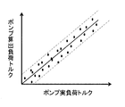
- the error state of the calculated torque is as shown in FIG.
- an error factor there is a detection error of the discharge pressure of the hydraulic pump 12 and a calculation error of the tilt amount of the hydraulic pump 12, as shown in FIG.
- the calculated load torque tends to have a certain error width. Therefore, it is effective to make a diagnosis and evaluation in a region where the pump load torque is large, in which such an error factor can be apparently reduced.
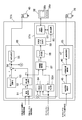
- FIG. 10 is a functional block diagram showing processing contents of the controller 37A according to the second embodiment of the present invention.
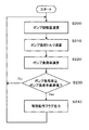
- FIG. 11A is a flowchart showing the processing contents of the pump displacement calculating section 64 and the state determining section 56A.
- step S230 It is determined whether or not the hydraulic pump 12 is present (step S230). When the pump load factor is equal to or greater than the predetermined pump load factor, it is determined that the hydraulic pump 12 is in a predetermined load state, and an effective operation flag is output (step S230). S240).
- FIG. 11B is a functional block diagram showing the processing contents of the pump displacement calculating unit 64.
- the pump displacement calculating section 64 includes a limited displacement calculating section 70 and a minimum value selecting section 71.
- the torque characteristic of the hydraulic pump 12 shown in FIG. 6 is set in the limited displacement amount calculation unit 70, and the pump displacement amount calculation unit 64 determines the torque of the speed sensing control in the limited displacement amount calculation unit 70.
- the limited pump tilt amount of the speed sensing control is calculated. That is, the limited tilting amount calculation unit 70 updates the torque characteristic of the hydraulic pump 12 so that the maximum torque decreases as the torque command value Ta decreases, and makes the torque characteristic refer to the discharge pressure of the hydraulic pump 12. Then, the limit pump tilt amount of the speed sensing control at that time is calculated.
- the minimum pumping amount calculating unit 64 in the minimum value selecting unit 71 calculates the limited pump tilting amount calculated by the limited tilting amount calculating unit 70 and the target tilt calculated by the flow control calculating unit 65 of the positive pump control. The smaller amount is selected as the current tilt amount of the hydraulic pump 12.
- the pump displacement calculating unit 64 estimates the current displacement of the hydraulic pump 12 by performing a calculation process simulating the operation of the regulator 24.
- the value measured by the position sensor may be used instead of the value calculated by the pump displacement amount calculation unit 64.
- FIG. 11C is a functional block diagram showing processing contents of the state determination unit 56A.
- FIG. 11C shows a case where there are two hydraulic pumps.
- the state determination unit 56A includes torque calculation units 72a and 72b, an addition unit 73, a pump load ratio calculation unit 74, a pump load ratio reference value setting unit 75, and a comparison unit 76.
- the state determination unit 56A uses the above-described equation in the torque calculation unit 72a, using the displacement amount of the hydraulic pump 12 calculated by the pump displacement amount calculation unit 64 and the discharge pressure of the hydraulic pump 12 detected by the pressure sensor 21. , The load torque of the hydraulic pump 12 is calculated. Similarly, the torque calculation unit 72b calculates the load torque of a hydraulic pump (not shown). Next, the adding unit 73 calculates the total load torque of the two hydraulic pumps by adding the load torques. Next, the state determination unit 56A calculates the pump load ratio by dividing the total load torque of the two hydraulic pumps by the maximum pump torque Tmax of the hydraulic pump 12 in the pump load ratio calculation unit 74.
- the engine diagnosis calculation unit 67A calculates the characteristic amount based on the valid operation flag in the same manner as in the first embodiment, so that trend data for engine diagnosis can be displayed on the display device 38.
- the load factor is 70% or less, the condition is not satisfied, so that a new feature value is not calculated, and the previous value is held.
- the load factor is 70% or more, the valid operation flag becomes a true value, and the following calculation is performed as in the first embodiment.
- the effective operation flag and the torque correction amount ⁇ Ta are input, the torque correction amount ⁇ Ta is validated, the torque correction amount ⁇ Ta * is fetched, and the filter processing section 58 converts the torque correction amount ⁇ Ta * into the torque correction amount ⁇ Ta *.
- a low-pass filter process is performed on the low-pass filter to obtain a feature value at the current time.
- the time history data generation unit 59 calculates the magnitude and change of the feature amount and adds time history information to generate time history data of the engine diagnosis feature amount, and stores it in the storage device 60.
- the display calculation unit 61 reads out time history data of the feature amount for a predetermined period stored in the storage device 60, and uses the time history data as trend data for engine diagnosis to the display device 38. Display.
- the pump load factor reference value is set to 70%. However, if it is desired to secure and evaluate more operation scenes for acquiring diagnostic data, the load factor may be further reduced.
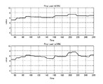
- FIGS. 12 and 13 show examples of feature amount trend data when the load factor reference values are different. 12 and 13 show the case where the load factor reference value is 70% and the case where the load factor reference value is 50%. FIG. 12 shows a case where the change in the feature amount is relatively small, and FIG. Is shown.
- the case where the load factor reference value of each of FIGS. 12 and 13 is 70% and the case where the load factor reference value is 50%
- the case where the load factor reference value is 50% is the case where the load factor reference value is 70%. Since more features are used than before, it is possible to evaluate more detailed changes. However, as described above, the load factor is small, so errors and the like enter, and as a result, the influence of noise is reduced. Easier to receive. Therefore, it is desirable to set the pump load factor reference value in consideration of the balance between the number of feature amount data to be used and the effect of noise.
- the load factor reference value can be arbitrarily changed from the outside so that the load factor reference value can be set according to the situation.
- FIG. 11C also shows such a modification. That is, a load factor indicating device 77 is provided as shown by a dashed line in FIG. 11B, and the operator can operate the load factor indicating device 77 to adjust the load factor reference value of the pump load factor reference value setting unit. .
- a plurality of load factor reference values may be set, and a feature amount may be calculated to display trend data. Good.
- the control amount calculation unit 57, the filter processing unit 58, the time history data generation unit 59, the storage device 60, and the display calculation unit 61 calculate the respective feature amounts in response to the first and second valid operation flags. , So that trend data can be displayed.
- FIG. 14 is a diagram showing an example of engine diagnosis trend data displayed on the display screen 38b of the display device 38 in such a modification.
- two types of trend data reflecting the variation tendency of the feature amount are displayed on the display screen 38b, and these two types of trend data can be simultaneously checked.
- a confirmer such as an operator or a maintenance person can simultaneously confirm diagnostic data based on a plurality of load factor reference values, make a decision while confirming progress, and grasp a stable result.
Abstract
Diagnostic precision of engine deterioration is improved while suppressing the cost required for the operation of diagnosing deterioration such as reduction in output of the engine. Toward this end, a controller 37 (engine diagnosis device): determines whether a hydraulic pump 12 is in a preset load state for acquiring diagnosis data of the engine 10 (operation scene in which the load torque of a hydraulic pump 12 is stabilized); activates, as diagnosis data for the engine 10, a control amount relating to a torque command value Ta for a speed-sensing control when the hydraulic pump 12 is determined to be in the preset load state; generates time history data using the activated control amount as the present feature amount; and makes the time history data displayable on a display device 38 as trend data for engine diagnosis.
Description
本発明は、エンジン診断装置を備えた油圧ショベル、クレーン等の建設機械に関する。
The present invention relates to a construction machine such as a hydraulic shovel or a crane provided with an engine diagnosis device.
油圧ショベル、クレーン等の建設機械においては、油圧駆動システムの動力源として一般にディーゼルエンジン(以下単にエンジンという)が使用されている。このエンジンの異常はエンジンの出力低下につながり、建設機械の性能の低下及び動作の制限をきたす等、重大な影響を及ぼすため、異常を検知して予防保全を行うことが求められている。そこで、従来から様々なエンジン診断技術が提案されている。
建設 In construction machines such as hydraulic excavators and cranes, a diesel engine (hereinafter simply referred to as an engine) is generally used as a power source of a hydraulic drive system. This abnormality of the engine leads to a decrease in the output of the engine, and serious effects such as a decrease in the performance of the construction machine and a restriction on the operation. Therefore, it is required to detect the abnormality and perform preventive maintenance. Therefore, various engine diagnosis techniques have been conventionally proposed.
例えば、エンジン診断技術として特許4853921号公報に記載されているものが知られている。
For example, there is known an engine diagnostic technology described in Japanese Patent No. 4853921.
この従来技術では、エンジン出力と関連する信号の大きさと、その発生頻度の関係を表す頻度分布情報を一定時間稼働毎に車体の管理用コントローラにて収集し、それらデータを無線通信機能により蓄積サーバへ送信してデータを蓄積する。そして、これら蓄積された複数の頻度分布情報を時系列に並べて比較することでエンジンの出力低下を検知し、エンジン出力低下を判断する。
In this conventional technique, frequency distribution information indicating the relationship between the magnitude of a signal related to an engine output and the frequency of occurrence is collected by a vehicle body management controller at regular intervals of operation, and the data is stored in a storage server by a wireless communication function. Send to and store the data. Then, by comparing the stored plurality of pieces of frequency distribution information in a time series and comparing them, a decrease in engine output is detected, and a decrease in engine output is determined.
この従来技術によれば、エンジン出力の大きさとその発生頻度情報が長期間に渡って確認することが可能になるので、車体毎の経年的な出力の低下等が確認でき、エンジンの劣化状況を把握することが可能になる。
According to this conventional technology, it is possible to check the magnitude of the engine output and its occurrence frequency information over a long period of time. It becomes possible to grasp.
特許文献1記載の従来のエンジン診断技術においては、エンジン出力相当の大きさとその頻度情報をある期間にわたり収集蓄積しておき、時系列的に比較するので、判定のための閾値が不要で、車体単体での特徴量の変化具合でエンジンの劣化具合を判断することができる。しかし、実際に作業機に作用する負荷は作業の内容によって異なるため、厳密には出力の違いは作業負荷の違いに影響を受ける。特に経年劣化を観察しようと長期にわたる作業内容は作業現場等も異なる場合があり、作業負荷が当然異なることが予想される。このような場合、エンジン出力傾向はその現場に影響を受けることになり、純粋にエンジンの性能を反映するものではなく、統計的な傾向としては多少評価できるかもしれないが、判定のための特徴量としては大きな不確かさ(誤差)を含むと考えられる。
In the conventional engine diagnosis technology described in Patent Document 1, the magnitude of the engine output and its frequency information are collected and accumulated over a period of time, and compared in a time-series manner. The degree of deterioration of the engine can be determined based on the degree of change in the feature amount of a single unit. However, since the load actually acting on the work machine differs depending on the content of the work, the difference in output is strictly affected by the difference in work load. In particular, when observing aging degradation, long-term work contents may be different at work sites and the like, and it is expected that the work load naturally differs. In such a case, the engine output tendency is affected by the site and does not purely reflect the engine performance, and may be somewhat evaluated as a statistical tendency, but the characteristics for judgment It is considered that the quantity includes a large uncertainty (error).
また、長期間における頻度情報が必要であることから、多量のデータが必要となり、演算処理のためのメモリ領域が必要で、演算のためのコスト(高級なコントローラ)も必要となる。特許文献1においては、そのコストを抑制するために車載コントローラではなく、遠隔通信を介して蓄積サーバ等を用いて処理するとしているが、これは車載コントローラのコストを抑制するためにとられた構成であり、現在の車載コントローラ技術、制御技術レベルにおいては、処理データが膨大であり、現在の車載コントローラでは対応が困難であることを裏付けるものと言える。また、蓄積サーバでは巨大なデータを扱うことも可能であるが、車体からの大量データを転送するための通信費用が別途必要とされ、この場合においても診断制御ロジック達成のためのコストが発生してしまう。
(4) Since long-term frequency information is required, a large amount of data is required, a memory area for computation processing is required, and computation costs (high-grade controller) are required. In Patent Literature 1, processing is performed using a storage server or the like via remote communication instead of an in-vehicle controller in order to suppress the cost. However, this is a configuration taken to suppress the cost of the in-vehicle controller. At the current in-vehicle controller technology and control technology level, the amount of processed data is enormous, which proves that it is difficult to cope with the current in-vehicle controller. In addition, the storage server can handle huge data, but communication costs for transferring large amounts of data from the vehicle are required separately, and in this case, costs for achieving the diagnostic control logic are also incurred. Would.
本発明は、このような状況を鑑みてなされたもので、エンジンの出力低下等の劣化診断の運用に要するコストを抑えつつ、エンジン劣化の診断精度を向上ることができる建設機械を提供することを目的とする。
The present invention has been made in view of such a situation, and provides a construction machine capable of improving the accuracy of diagnosis of engine deterioration while suppressing the cost required for operation of deterioration diagnosis such as engine output reduction. With the goal.
本発明は、上記目的を達成するため、エンジンと、このエンジンにより駆動される可変容量型の油圧ポンプと、前記油圧ポンプの吐出油により駆動される油圧アクチュエータと、前記油圧ポンプの入力トルクが最大吸収トルクを超えないよう前記油圧ポンプの押しのけ容積を制御するレギュレータとを備えた油圧システムと、前記油圧ポンプの負荷トルクが増大し前記エンジンの回転数が低下するにしたがって前記油圧ポンプの最大吸収トルクが減少するように前記レギュレータを制御するためのスピードセンシング制御のトルク指令値を演算するコントローラと、前記エンジンの診断を行うエンジン診断装置とを備えた建設機械において、前記エンジン診断装置は前記コントローラにより構成され、前記コントローラは、前記油圧ポンプが前記エンジンの診断データを取得するための予め定めた負荷状態にあるかどうかを判定し、前記油圧ポンプが前記予め定めた負荷状態にあると判定したときに、前記スピードセンシング制御のトルク指令値に係わる制御量を前記エンジンの診断データとして有効化し、この有効化した制御量を現在の特徴量として用いて時刻歴データを生成し、この時刻歴データをエンジン診断用のトレンドデータとして表示装置に表示可能とするものとする。
In order to achieve the above object, the present invention provides an engine, a variable displacement hydraulic pump driven by the engine, a hydraulic actuator driven by the discharge oil of the hydraulic pump, A hydraulic system comprising a regulator for controlling the displacement of the hydraulic pump so as not to exceed the absorption torque; and a maximum absorption torque of the hydraulic pump as the load torque of the hydraulic pump increases and the engine speed decreases. In a construction machine including a controller that calculates a torque command value of speed sensing control for controlling the regulator so that the regulator is reduced, and an engine diagnostic device that diagnoses the engine, the engine diagnostic device is controlled by the controller. Wherein the controller comprises the hydraulic pump It is determined whether or not the engine is in a predetermined load state for acquiring diagnostic data of the engine, and when it is determined that the hydraulic pump is in the predetermined load state, a torque command value of the speed sensing control is determined. The related control amount is validated as diagnostic data of the engine, time history data is generated using the validated control amount as a current feature amount, and the time history data is displayed as trend data for engine diagnosis on a display device. It shall be possible.
このようにコントローラにおいて、油圧ポンプが予め定めた負荷状態にあるかどうかを判定し、油圧ポンプが予め定めた負荷状態にあると判定したときに、スピードセンシング制御のトルク指令値に係わる制御量を前記エンジンの診断データとして有効化し、エンジン診断用のトレンドデータとして表示可能とすることにより、エンジンの診断データとしてコントローラに取り込まれるデータ量が大幅に減少し、エンジンの出力低下等の劣化診断の運用に要するコストを抑えることができる。
As described above, in the controller, it is determined whether the hydraulic pump is in a predetermined load state, and when it is determined that the hydraulic pump is in a predetermined load state, the control amount related to the torque command value of the speed sensing control is determined. By activating the diagnostic data of the engine and displaying it as trend data for engine diagnosis, the amount of data taken into the controller as diagnostic data of the engine is greatly reduced, and operation of deterioration diagnosis such as reduction in engine output is performed. Cost required for the operation can be suppressed.
また、エンジンの診断データとして、油圧ポンプが予め定めた負荷状態にあるときのスピードセンシング制御のトルク指令値に係わる制御量を有効化してエンジン診断用の時刻歴データを生成することで、計測誤差等に基づく診断ノイズを抑え、精度良くエンジンの出力低下状況を把握し、エンジン劣化の診断精度を向上させることができる。
In addition, as a diagnostic data of the engine, by enabling a control amount related to a torque command value of the speed sensing control when the hydraulic pump is in a predetermined load state, and generating time history data for engine diagnosis, a measurement error can be obtained. Thus, it is possible to suppress the diagnosis noise based on the above and the like, accurately grasp the engine output reduction state, and improve the diagnosis accuracy of engine deterioration.
本発明によれば、エンジンの出力低下等の劣化診断の運用に要するコストを抑えつつ、エンジン劣化の診断精度を向上させることができる。
According to the present invention, it is possible to improve the diagnosis accuracy of engine deterioration while suppressing the cost required for operating deterioration diagnosis such as engine output reduction.
以下、本発明の実施の形態を図面に基づいて説明する。
Hereinafter, embodiments of the present invention will be described with reference to the drawings.
<第1の実施の形態>
図1は、本発明に係わる建設機械の代表例である油圧ショベルを示す図である。 <First embodiment>
FIG. 1 is a diagram illustrating a hydraulic excavator that is a typical example of a construction machine according to the present invention.
図1は、本発明に係わる建設機械の代表例である油圧ショベルを示す図である。 <First embodiment>
FIG. 1 is a diagram illustrating a hydraulic excavator that is a typical example of a construction machine according to the present invention.
油圧ショベルは走行体101と、この走行体101上に配置される旋回体102と、この旋回体102に取り付けられるフロント作業機、すなわち作業装置103とを備えている。
The hydraulic excavator includes a traveling body 101, a revolving body 102 disposed on the traveling body 101, and a front working machine attached to the revolving body 102, that is, a working device 103.
走行体101は左右一対のクローラ101a,101b(図1では片側のみを示す)を有し、クローラ101a,101bはそれぞれ走行モータ110a,110b(片側のみを示す)によって駆動され、走行を行う。旋回体102は旋回モータ102aによって駆動され、走行体101上を旋回する。
The traveling body 101 has a pair of right and left crawlers 101a and 101b (only one side is shown in FIG. 1), and the crawlers 101a and 101b are driven by traveling motors 110a and 110b (only one side is shown) to travel. The swing body 102 is driven by a swing motor 102a, and swings on the traveling body 101.
作業装置103は、旋回体102に上下方向に回動可能に取り付けられるブーム104と、このブーム104に回動可能に取り付けられるアーム105と、このアーム105に回動可能に取り付けられるバケット106とで構成されている。ブーム104はブームシリンダ112によって駆動され、アーム105はアームシリンダ113によって駆動され、バケット106はバケットシリンダ114によって駆動される。旋回体102上の前側位置には、運転室を構成するキャビン120が備えられている
図2は、本発明の第1の実施の形態に係わる油圧ショベルに搭載される油圧システムとその制御システムを含む全体構成を示す図である。 Theworking device 103 includes a boom 104 that is rotatably attached to the revolving body 102 in the vertical direction, an arm 105 that is rotatably attached to the boom 104, and a bucket 106 that is rotatably attached to the arm 105. It is configured. The boom 104 is driven by a boom cylinder 112, the arm 105 is driven by an arm cylinder 113, and the bucket 106 is driven by a bucket cylinder 114. A cabin 120 constituting a cab is provided at a front position on the revolving superstructure 102. FIG. 2 shows a hydraulic system mounted on the hydraulic excavator according to the first embodiment of the present invention and a control system thereof. It is a figure showing the whole composition including.
図2は、本発明の第1の実施の形態に係わる油圧ショベルに搭載される油圧システムとその制御システムを含む全体構成を示す図である。 The
まず、油圧システムについて説明する。
First, the hydraulic system will be described.
油圧ショベルに搭載される油圧システムは、原動機であるディーゼルエンジン10(以下単にエンジンという)と、エンジン10により駆動される可変容量型の油圧ポンプ12と、複数の油圧アクチュエータ14(図2では便宜上1つのみ図示)に供給される圧油の流れを制御する複数の制御スプールを内蔵したコントロールバルブ16と、油圧ポンプ12の吐出油路に接続され、油圧ポンプ12からコントロールバルブ16に供給される圧力(油圧ポンプ12の吐出圧)の上限を規制するメインリリーフ弁18と、コントロールバルブ16に内蔵された複数の制御スプールを切り換える指令パイロット圧(操作信号)を生成する油圧パイロット式の複数の操作装置20(図2では便宜上1つのみ図示)と、複数の操作装置20からコントロールバルブ16に導かれる指令パイロット圧のうち最も高い指令パイロット圧を選択してポンプ流量制御圧を生成する複数のシャトル弁を内蔵したシャトル弁ブロック22と、油圧ポンプ12の傾転量(押しのけ容積、つまり容量)を制御し、油圧ポンプ12の吐出流量を制御するレギュレータ24とを備えている。
The hydraulic system mounted on the hydraulic excavator includes a diesel engine 10 (hereinafter simply referred to as an engine) as a prime mover, a variable displacement hydraulic pump 12 driven by the engine 10, and a plurality of hydraulic actuators 14 (in FIG. And a control valve 16 having a plurality of control spools for controlling the flow of pressure oil supplied to the hydraulic pump 12 and a pressure supplied from the hydraulic pump 12 to the control valve 16. A main relief valve 18 that regulates the upper limit of (discharge pressure of the hydraulic pump 12), and a plurality of hydraulic pilot-type operating devices that generate a command pilot pressure (operation signal) for switching a plurality of control spools built in the control valve 16. 20 (only one is shown in FIG. 2 for convenience) and a plurality of operating devices 20 A shuttle valve block 22 containing a plurality of shuttle valves for selecting the highest command pilot pressure from among the command pilot pressures guided to the valve 16 and generating a pump flow control pressure, and a tilting amount (displacement, That is, a regulator 24 that controls the discharge capacity of the hydraulic pump 12 is controlled.
複数の操作装置20はそれぞれ操作レバー20aを有し、オペレータが操作レバー20aを操作することにより指令パイロット圧が生成され、この指令パイロット圧がコントロールバルブ16に導かれることにより対象の油圧アクチュエータが駆動される。
Each of the plurality of operation devices 20 has an operation lever 20a, and an operator operates the operation lever 20a to generate a command pilot pressure. The command pilot pressure is guided to the control valve 16 to drive a target hydraulic actuator. Is done.
このように油圧ポンプ12から吐出された圧油を、コントロールバルブ16を介して油圧アクチュエータ14に供給することで、図1に示した油圧ショベルが動作する仕組みになっている。
圧 By supplying the pressure oil discharged from the hydraulic pump 12 to the hydraulic actuator 14 via the control valve 16, the hydraulic shovel shown in FIG. 1 operates.
レギュレータ24は、油圧ポンプ12の押しのけ容積変更部材(例えば斜板)を駆動するポンプアクチュエータ26と、このポンプアクチュエータ26に導かれる油圧を制御して油圧ポンプ12の傾転量を制御するポンプ流量制御弁28及びポンプトルク制御弁30とを有している。
The regulator 24 includes a pump actuator 26 that drives a displacement changing member (for example, a swash plate) of the hydraulic pump 12, and a pump flow control that controls a hydraulic pressure guided to the pump actuator 26 to control a tilt amount of the hydraulic pump 12. It has a valve 28 and a pump torque control valve 30.
次に、制御システムについて説明する。
Next, the control system will be described.
制御システムは、オペレータの回転操作によってエンジン10の目標回転数の指示信号を生成する回転ダイヤル式の目標回転数指示装置32と、エンジン10の回転数(実回転数)を検出するエンジン回転センサ33と、油圧ポンプ12の吐出圧を検出する圧力センサ21と、複数の操作装置20により生成される指令パイロット圧(操作信号)を検出する操作検出装置としての複数の圧力センサ35(図2では便宜上1つのみ図示)と、シャトル弁ブロック22によって生成されたポンプ流量制御圧を検出する圧力センサ36と、目標回転数指示装置32からの指示信号、エンジン回転センサ33及び圧力センサ21,35,36からの検出信号を入力し、所定の演算処理を行うコントローラ37と、コントローラ37からの表示信号を入力し、特徴量の時刻歴データ(後述)を表示する表示装置38と、コントローラ37からの指令信号を入力し、レギュレータ24のポンプ流量制御弁28及びポンプトルク制御弁30にそれぞれ流量制御圧及びトルク制御圧を出力する流量制御電磁弁39及びトルク制御電磁弁40とを備えている。
The control system includes a rotary dial-type target rotation speed indicating device 32 that generates an instruction signal of a target rotation speed of the engine 10 by an operator's rotation operation, and an engine rotation sensor 33 that detects the rotation speed (actual rotation speed) of the engine 10. 2, a pressure sensor 21 for detecting the discharge pressure of the hydraulic pump 12, and a plurality of pressure sensors 35 as operation detection devices for detecting a command pilot pressure (operation signal) generated by the plurality of operation devices 20 (for convenience in FIG. 2, Only one is shown), a pressure sensor 36 for detecting the pump flow rate control pressure generated by the shuttle valve block 22, an instruction signal from the target rotational speed instruction device 32, an engine rotational sensor 33, and pressure sensors 21, 35, 36. A controller 37 that receives a detection signal from the controller 37 and performs predetermined arithmetic processing, and a display signal from the controller 37 And input a command signal from the controller 37 to the pump flow control valve 28 and the pump torque control valve 30 of the regulator 24. A flow control solenoid valve 39 and a torque control solenoid valve 40 for outputting a torque control pressure are provided.
図3はレギュレータ24の詳細を示す図である。
FIG. 3 is a diagram showing details of the regulator 24.
レギュレータ24は、油圧ポンプ12の押しのけ容積変更部材を駆動するポンプアクチュエータ26と、このポンプアクチュエータ26に導かれる駆動圧を制御して油圧ポンプの傾転量を制御するポンプ流量制御弁28及びポンプトルク制御弁30とを有している。
The regulator 24 includes a pump actuator 26 that drives a displacement changing member of the hydraulic pump 12, a pump flow control valve 28 that controls a tilt amount of the hydraulic pump by controlling a driving pressure guided to the pump actuator 26, and a pump torque. And a control valve 30.
ポンプアクチュエータ26は、大径受圧部26bと小径受圧部26cを有する段付きの作動ピストン26aを備えたサーボピストンであり、大径受圧部26bには、ポンプ流量制御弁28及びポンプトルク制御弁30でタンク圧からパイロットポンプPpの一定のパイロット圧の範囲内の圧力に調整された制御圧が導かれ、小径受圧部26cにはパイロットポンプPpの一定のパイロット圧が導かれる。両受圧部26b,26cに共に同じパイロットポンプPpの一定のパイロット圧が導かれるとき、作動ピストン26aは図示左方向に移動し、油圧ポンプ12の斜板の傾転量を小さくしてポンプ吐出流量を減少させ、大径受圧部26bに導かれる圧力が低下すると、作動ピストン26aは図示右方向に移動し、油圧ポンプ12の斜板の傾転量を大きくしてポンプ吐出流量を増大させる。
The pump actuator 26 is a servo piston having a stepped working piston 26a having a large-diameter pressure receiving portion 26b and a small-diameter pressure receiving portion 26c. The large-diameter pressure receiving portion 26b has a pump flow control valve 28 and a pump torque control valve 30. Thus, a control pressure adjusted from the tank pressure to a pressure within a range of a constant pilot pressure of the pilot pump Pp is led, and a constant pilot pressure of the pilot pump Pp is led to the small-diameter pressure receiving portion 26c. When a constant pilot pressure of the same pilot pump Pp is guided to both the pressure receiving portions 26b and 26c, the working piston 26a moves to the left in the drawing, and the tilt amount of the swash plate of the hydraulic pump 12 is reduced to reduce the pump discharge flow rate. When the pressure guided to the large-diameter pressure receiving portion 26b decreases, the working piston 26a moves rightward in the drawing, increasing the amount of tilt of the swash plate of the hydraulic pump 12 to increase the pump discharge flow rate.
ポンプ流量制御弁28は流量制御電磁弁39から出力された流量制御圧が導かれる受圧部28aを有している。
The pump flow control valve 28 has a pressure receiving portion 28 a to which the flow control pressure output from the flow control solenoid valve 39 is guided.
流量制御電磁弁39から出力された流量制御圧が低くなるとポンプ流量制御弁28のスプールは図示左方向に移動し、パイロットポンプPpからの一定のパイロット圧がポンプ流量制御弁28とポンプトルク制御弁30を通り大径受圧部26bに導かれ、油圧ポンプ12の傾転量は小さくなりポンプ吐出流量が減少する。
When the flow control pressure output from the flow control solenoid valve 39 decreases, the spool of the pump flow control valve 28 moves to the left in the drawing, and a constant pilot pressure from the pilot pump Pp is applied to the pump flow control valve 28 and the pump torque control valve. The hydraulic pump 12 is guided to the large-diameter pressure receiving portion 26b through 30 and the amount of tilt of the hydraulic pump 12 is reduced, and the pump discharge flow rate is reduced.
流量制御電磁弁39から出力されたポンプ流量制御圧が高くなるとポンプ流量制御弁28のスプールは図示右方向に移動し、大径受圧部26bがポンプトルク制御弁30とポンプ流量制御弁28を通りドレン(タンク)に導かれ、油圧ポンプ12の傾転量は大きくなりポンプ吐出流量が増大する。
When the pump flow control pressure output from the flow control solenoid valve 39 increases, the spool of the pump flow control valve 28 moves rightward in the figure, and the large-diameter pressure receiving portion 26b passes through the pump torque control valve 30 and the pump flow control valve 28. Guided to the drain (tank), the amount of tilt of the hydraulic pump 12 increases, and the pump discharge flow rate increases.
このようにポンプ流量制御弁28は、ポンプ流量制御圧に応じたポンプ流量となるようにポンプ吐出流量を制御する。
Thus, the pump flow control valve 28 controls the pump discharge flow so as to have a pump flow corresponding to the pump flow control pressure.
ポンプトルク制御弁30は、油圧ポンプ12の吐出圧が導かれる受圧部30aと、トルク制御電磁弁40から出力されたトルク制御圧が導かれる受圧部30bを有し、受圧部30a,30bの反対側にバネ30cが位置している。
The pump torque control valve 30 has a pressure receiving portion 30a to which the discharge pressure of the hydraulic pump 12 is guided, and a pressure receiving portion 30b to which the torque control pressure output from the torque control solenoid valve 40 is guided, and is opposite to the pressure receiving portions 30a and 30b. The spring 30c is located on the side.
受圧部30aに導かれる油圧ポンプ12の吐出圧による油圧力がバネ30cの付勢力と受圧部30bに導かれるトルク制御電磁弁40のトルク制御圧による油圧力との差の値より低いとき、ポンプトルク制御弁30のスプールは図示右方向に移動し、大径受圧部26bをポンプ流量制御弁28に連通させ、ポンプ流量制御弁28によって決まるポンプ吐出流量となる。
When the hydraulic pressure due to the discharge pressure of the hydraulic pump 12 guided to the pressure receiving portion 30a is lower than the difference between the urging force of the spring 30c and the hydraulic pressure due to the torque control pressure of the torque control solenoid valve 40 guided to the pressure receiving portion 30b, The spool of the torque control valve 30 moves to the right in the figure, and connects the large-diameter pressure receiving portion 26b to the pump flow control valve 28, so that the pump discharge flow rate is determined by the pump flow control valve 28.
受圧部30aに導かれる油圧ポンプ12の吐出圧による油圧力がバネ30cの付勢力と受圧部30bに導かれるトルク制御電磁弁40からのトルク制御圧による油圧力との差の値より高くなるとポンプトルク制御弁30のスプールは図示左方向に移動すると、パイロットポンプPpからの一定のパイロット圧がポンプトルク制御弁30を通り大径受圧部26bに導かれ、油圧ポンプ12の傾転量は小さくなりポンプ吐出流量が減少する。
When the hydraulic pressure due to the discharge pressure of the hydraulic pump 12 guided to the pressure receiving portion 30a becomes higher than the difference between the urging force of the spring 30c and the hydraulic pressure due to the torque control pressure from the torque control solenoid valve 40 guided to the pressure receiving portion 30b, the pump is activated. When the spool of the torque control valve 30 moves to the left in the figure, a constant pilot pressure from the pilot pump Pp passes through the pump torque control valve 30 to the large-diameter pressure receiving portion 26b, and the tilt amount of the hydraulic pump 12 decreases. Pump discharge flow decreases.
このように油圧ポンプ12の吐出圧の上昇に応じて油圧ポンプ12の吐出流量を減少させ、油圧ポンプ12の吸収トルクが、バネ30cの付勢力と受圧部30bに導かれるトルク制御電磁弁40からのトルク制御圧による油圧力との差の値により決まる最大トルクを超えないよう制御される。
As described above, the discharge flow rate of the hydraulic pump 12 is reduced according to the rise of the discharge pressure of the hydraulic pump 12, and the absorption torque of the hydraulic pump 12 is controlled by the urging force of the spring 30c and the torque control solenoid valve 40 guided to the pressure receiving portion 30b. Is controlled so as not to exceed the maximum torque determined by the value of the difference between the torque control pressure and the hydraulic pressure.
また、その最大トルクはトルク制御電磁弁40からのトルク制御圧により可変である。この点については後述する。
The maximum torque is variable by the torque control pressure from the torque control solenoid valve 40. This will be described later.
図4は、コントローラ37の処理内容を示す機能ブロック図である。
FIG. 4 is a functional block diagram showing the processing contents of the controller 37.
コントローラ37は、油圧ポンプ12がエンジン10の診断データを取得するための予め定めた負荷状態にあるかどうかを判定し、油圧ポンプ12が予め定めた負荷状態にあると判定したときに、スピードセンシング制御のトルク指令値に係わる制御量をエンジン10の診断データとして有効化し、この有効化した制御量を現在の特徴量として用いて時刻歴データを生成し、この時刻歴データをエンジン診断用のトレンドデータとして表示装置38に表示可能とする。
The controller 37 determines whether or not the hydraulic pump 12 is in a predetermined load state for acquiring diagnostic data of the engine 10, and when determining that the hydraulic pump 12 is in a predetermined load state, performs speed sensing. The control amount related to the torque command value of the control is validated as diagnostic data of the engine 10, time history data is generated using the validated control amount as a current feature amount, and the time history data is used as a trend for engine diagnosis. It can be displayed on the display device 38 as data.
以下、その詳細を説明する。
The details are described below.
コントローラ37は、ポジティブポンプ制御の流量制御演算部65とスピードセンシング制御のトルク制御演算部66とを有している。
The controller 37 has a flow control operation unit 65 for positive pump control and a torque control operation unit 66 for speed sensing control.
流量制御演算部65は、圧力センサ36により検出されたポンプ流量制御圧(最も高い指令パイロット圧)に基づいて要求流量を算出する要求流量演算部45と、算出した要求流量から油圧ポンプ12の目標傾転量を算出する目標傾転量演算部46と、算出した目標傾転量を流量制御電磁弁39の指令電流に変換して出力する電流変換部47とを有している。
The flow rate control calculation unit 65 calculates a required flow rate based on the pump flow control pressure (highest command pilot pressure) detected by the pressure sensor 36, and a target flow rate of the hydraulic pump 12 based on the calculated required flow rate. It has a target tilt amount calculator 46 for calculating the tilt amount, and a current converter 47 for converting the calculated target tilt amount into a command current for the flow control solenoid valve 39 and outputting the same.
図5は、要求流量演算部45と目標傾転量演算部46の演算内容を示す機能ブロック図である。要求流量演算部45は、ポンプ流量制御圧が高くなるにしたがって要求流量が増大するポンプ流量制御圧と要求流量のテーブルが設定されており、圧力センサ36により検出されたポンプ流量制御圧をそのテーブルに参照させることにより対応する要求流量を算出する。目標傾転量演算部46は、要求流量が増大するに従って目標傾転量が増大する要求流量と目標傾転量のテーブルが設定されており、算出された要求流量をそのテーブルに参照させることにより対応する目標傾転量を算出する。
FIG. 5 is a functional block diagram showing calculation contents of the required flow rate calculation unit 45 and the target tilt amount calculation unit 46. The required flow rate calculation unit 45 has a table of a pump flow rate control pressure and a required flow rate in which the required flow rate increases as the pump flow rate control pressure increases, and the pump flow rate control pressure detected by the pressure sensor 36 is stored in the table. , The corresponding required flow rate is calculated. The target displacement amount calculation unit 46 sets a table of the required flow rate and the target displacement amount in which the target displacement amount increases as the required flow rate increases, and refers to the calculated required flow rate in the table. The corresponding target tilt amount is calculated.
電流変換部47は目標傾転量が大きくなるにしたがって大きくなる指令電流を生成するように構成されており、流量制御電磁弁39はその指令電流により励磁され、流量制御圧力をポンプ流量制御弁28の受圧部28aに出力し、前述したように油圧ポンプ12の吐出流量が制御される。これにより油圧ポンプ12は、操作装置20の操作レバー20aの操作量(要求流量)に応じて油圧ポンプ12の吐出流量を増加させる、ポジティブポンプ制御と呼ばれる方式で油圧ポンプ12の吐出流量を制御することができる。
The current conversion unit 47 is configured to generate a command current that increases as the target tilt amount increases, and the flow control solenoid valve 39 is excited by the command current to change the flow control pressure to the pump flow control valve 28. And the discharge flow rate of the hydraulic pump 12 is controlled as described above. Accordingly, the hydraulic pump 12 controls the discharge flow rate of the hydraulic pump 12 by a method called positive pump control, in which the discharge flow rate of the hydraulic pump 12 is increased according to the operation amount (required flow rate) of the operation lever 20a of the operation device 20. be able to.
図4に戻り、スピードセンシング制御のトルク制御演算部66は、目標回転数指示装置32によって指示されたエンジン10の目標回転数とエンジン回転センサ33によって検出されたエンジン10の実回転数に基づいて、実回転数-目標回転数=回転数偏差の演算を行い、回転数偏差ΔNを算出する偏差演算部51と、算出した回転数偏差ΔNからトルク補正量ΔTaを算出する補正量演算部52と、ショベルの運転動作やモード等から定まる油圧ポンプ12の基準トルクT0を算出する基準トルク演算部53と、この基準トルクT0に前記トルク補正量ΔTaを加算することで基準トルクT0を補正し、油圧ポンプ12の新たなトルク指令値Taを算出する加算部54と、算出したトルク指令値Taをトルク制御電磁弁40の指令電流に変換して出力する電流変換部55とを有している。電流変換部55はトルク指令値Taが基準トルクT0より小さくなるにしたがって大きくなる指令電流を出力するように構成されており、トルク制御電磁弁40はその指令電流により励磁され、トルク制御圧力をポンプトルク制御弁30の受圧部30bに出力し、前述したように油圧ポンプ12の最大吸収トルクが制御される。
Returning to FIG. 4, the torque control calculation unit 66 of the speed sensing control is based on the target rotation speed of the engine 10 indicated by the target rotation speed instruction device 32 and the actual rotation speed of the engine 10 detected by the engine rotation sensor 33. The actual rotation speed-target rotation speed = a rotation speed deviation, and calculates a rotation speed deviation ΔN, and a correction amount calculation unit 52 that calculates a torque correction amount ΔTa from the calculated rotation speed deviation ΔN. A reference torque calculation unit 53 for calculating a reference torque T0 of the hydraulic pump 12 determined from the operation operation and mode of the shovel, and the reference torque T0 is corrected by adding the torque correction amount ΔTa to the reference torque T0. An adder 54 for calculating a new torque command value Ta of the pump 12, and converting the calculated torque command value Ta into a command current for the torque control solenoid valve 40 and outputting the same. And a current conversion unit 55 to be. The current converter 55 is configured to output a command current that increases as the torque command value Ta becomes smaller than the reference torque T0, and the torque control solenoid valve 40 is excited by the command current to pump the torque control pressure. The output is output to the pressure receiving portion 30b of the torque control valve 30, and the maximum absorption torque of the hydraulic pump 12 is controlled as described above.
図6は、トルク制御電磁弁40からのトルク制御圧により設定される油圧ポンプ12のトルク特性及び最大トルクの変化を示す図である。補正量演算部52により演算されたトルク補正量ΔTaがゼロで、加算部54が基準トルク演算部53で算出された基準トルクT0に等しいトルク指令値Taを算出し、トルク制御電磁弁40からポンプトルク制御弁30の受圧部30bに出力されるトルク制御圧が所定の値にあるとき、レギュレータ24によって設定される油圧ポンプ12のトルク特性及び最大トルクはそれぞれSa及びTmaxaである。油圧ポンプ12の吸収トルク(負荷トルク)が増加してエンジン10の実回転数が低下すると、トルク補正量ΔTaは負の値となり、加算部54で算出されるトルク指令値Taは減少する。このとき、トルク指令値Taの減少に伴ってトルク制御電磁弁40がポンプトルク制御弁30の受圧部30bに出力するトルク制御圧は上昇し、このトルク制御圧が上昇するにしたがって、レギュレータ24によって設定される油圧ポンプ12のトルク特性及び最大トルクは、図6に矢印で示すように、それぞれSa及びTmaxaからSb及びTmaxb,Sc及びTmaxcと減少する。
FIG. 6 is a diagram showing changes in the torque characteristics and the maximum torque of the hydraulic pump 12 set by the torque control pressure from the torque control solenoid valve 40. The torque correction amount ΔTa calculated by the correction amount calculation unit 52 is zero, and the addition unit 54 calculates a torque command value Ta equal to the reference torque T0 calculated by the reference torque calculation unit 53. When the torque control pressure output to the pressure receiving portion 30b of the torque control valve 30 is at a predetermined value, the torque characteristics and the maximum torque of the hydraulic pump 12 set by the regulator 24 are Sa and Tmaxa, respectively. When the absorption torque (load torque) of the hydraulic pump 12 increases and the actual rotation speed of the engine 10 decreases, the torque correction amount ΔTa becomes a negative value, and the torque command value Ta calculated by the adding unit 54 decreases. At this time, as the torque command value Ta decreases, the torque control pressure output from the torque control solenoid valve 40 to the pressure receiving portion 30b of the pump torque control valve 30 increases, and as the torque control pressure increases, the regulator 24 The set torque characteristics and maximum torque of the hydraulic pump 12 decrease from Sa and Tmaxa to Sb, Tmaxb, Sc and Tmaxc, respectively, as indicated by arrows in FIG.
油圧ショベルのようにエンジン10を用いて油圧ポンプ12を駆動する場合、油圧ポンプ12の負荷がエンジンのトルクを上回るとポンプ駆動ができなくなりエンジンストップに至ってしまう。このエンジンストップを防止するためにエンジン10のスピードセンシング制御のトルク制御演算部66が設けられている。
(4) When the hydraulic pump 12 is driven using the engine 10 like a hydraulic excavator, if the load of the hydraulic pump 12 exceeds the engine torque, the pump cannot be driven and the engine stops. In order to prevent the engine from stopping, a torque control calculator 66 for speed sensing control of the engine 10 is provided.
このスピードセンシング制御によれば、エンジン出力(トルク)等が何らかの要因によって低下した場合でも、油圧ポンプ12の出力(吸収トルク)が調整されることになり、エンジン出力とポンプ吸収トルクがバランスした状態に制御されることになる。したがって、このポンプ制御状態を把握することで、エンジン10の駆動状態を間接的に把握することが可能になる。
According to this speed sensing control, the output (absorption torque) of the hydraulic pump 12 is adjusted even when the engine output (torque) or the like decreases for some reason, and the engine output and the pump absorption torque are balanced. Will be controlled. Therefore, by grasping the pump control state, it is possible to indirectly grasp the driving state of the engine 10.
コントローラ37は、更に、エンジン10の診断を行うエンジン診断装置としてのエンジン診断演算部67を有している。エンジン診断演算部67は上記のような考えに基づいて、スピードセンシング制御によるポンプ制御状態を把握することでエンジン10の診断を行う。
The controller 37 further includes an engine diagnosis calculation unit 67 as an engine diagnosis device that diagnoses the engine 10. The engine diagnosis calculation unit 67 diagnoses the engine 10 by grasping the pump control state by the speed sensing control based on the above idea.
図4において、エンジン診断演算部67は、油圧ポンプ12がエンジン10の診断データを取得するための予め定めた負荷状態にあるかどうかを判定する状態判定部56と、この状態判定部56の判定結果が満たされ(真であり)、油圧ポンプ12が予め定めた負荷状態にあると判定したときに、上記スピードセンシング制御のトルク指令値Taに係わる制御量であるトルク補正量ΔTaをエンジン10の診断データとして有効化して取り込む制御量演算部57と、この有効化したトルク補正量ΔTa*(有効化した制御量)に対して安定化のためのローパスフィルタ処理を施すフィルタ処理部58と、フィルタ処理部58を経由した有効化したトルク補正量ΔTa*(有効化した制御量)を現在の特徴量として用い、この特徴量に対してその大きさやその変化を算出しかつ時刻歴情報を付加し、エンジン診断用の特徴量の時刻歴データを生成する時刻歴データ生成部59と、生成した特徴量の時刻歴データを保存する記憶装置60と、表示装置38からの表示要求に応じて記憶装置60に保存した所定期間の特徴量の時刻歴データを読み出し、この時刻歴データをエンジン診断用のトレンドデータとして表示装置38に表示させる表示演算部61とを有している。
In FIG. 4, an engine diagnosis calculation unit 67 determines whether or not the hydraulic pump 12 is in a predetermined load state for obtaining diagnosis data of the engine 10, and a determination by the state determination unit 56. When the result is satisfied (true) and it is determined that the hydraulic pump 12 is in a predetermined load state, the torque correction amount ΔTa, which is a control amount related to the torque command value Ta of the speed sensing control, is set to A control amount calculation unit 57 that is validated and taken in as diagnostic data; a filter processing unit 58 that performs a low-pass filter process for stabilization on the validated torque correction amount ΔTa * (validated control amount); The validated torque correction amount ΔTa * (validated control amount) passed through the processing unit 58 is used as the current feature amount, and the magnitude of this feature amount is A time history data generation unit 59 for calculating the change and adding time history information to generate time history data of the feature amount for engine diagnosis; a storage device 60 for storing the generated time history data of the feature amount; In response to a display request from the display device 38, the display operation unit 61 reads out the time history data of the feature amount for a predetermined period stored in the storage device 60, and displays the time history data as trend data for engine diagnosis on the display device 38. And
表示装置38は、操作部38aと表示画面38bを有し、操作部38aを操作して表示要求信号をコントローラ37出力し、コントローラ37の表示演算部61を介して記憶装置60から取得した所定期間の特徴量の時刻歴データをエンジン診断用のトレンドデータとして表示画面38bに表示する。
The display device 38 has an operation unit 38a and a display screen 38b. The operation unit 38a is operated to output a display request signal to the controller 37. Are displayed on the display screen 38b as trend data for engine diagnosis.
なお、エンジン診断演算部67は、制御量演算部57においてエンジンの診断データとして有効化する制御量をトルク補正量ΔTaとしたが、スピードセンシング制御のトルク指令値Taに係わる制御量であれば、それ以外の制御量であってもよい。例えば、補正量演算部52が比例要素の演算部である場合は、比例係数倍異なる前段入力の回転数偏差ΔNを制御量としても同様の効果が得られる。また、スピードセンシング制御のトルク指令値Taそのものを制御量としてもよい。
The engine diagnosis calculation unit 67 sets the control amount validated as the engine diagnosis data in the control amount calculation unit 57 to the torque correction amount ΔTa. However, if the control amount is related to the torque command value Ta of the speed sensing control, Other control amounts may be used. For example, when the correction amount calculation unit 52 is a calculation unit of a proportional element, the same effect can be obtained even if the rotation speed deviation ΔN of the previous-stage input that is different by a factor of proportionality is used as the control amount. Further, the torque command value Ta itself of the speed sensing control may be used as the control amount.
また、表示装置38は、油圧ショベルに備えられるものに限らず、管理室等の外部に備えられた表示装置であってもよく、その場合は、無線通信手段を介して情報のやり取りを行えばよい。
Further, the display device 38 is not limited to the one provided in the hydraulic excavator, and may be a display device provided outside the management room or the like. In that case, if information is exchanged via wireless communication means, Good.
次に、状態判定部56の判定処理の詳細を説明する。
Next, details of the determination processing of the state determination unit 56 will be described.
本実施の形態では、状態判定部56において、エンジン10の診断データを取得するために予め定めた油圧ポンプ12の負荷状態を、エンジン10の診断条件を満たす油圧システムの特定の動作シーンに限定して、トルク補正値ΔTaをエンジンの診断データとして有効化するものである。ここで、エンジン10の診断条件を満たす油圧システムの特定の動作シーンとは、油圧ポンプ12の負荷トルク(吸収トルク)が安定した状態となる動作シーンを意味する。
In the present embodiment, in the state determination unit 56, the load state of the hydraulic pump 12 predetermined to acquire the diagnostic data of the engine 10 is limited to a specific operation scene of the hydraulic system satisfying the diagnostic conditions of the engine 10. Thus, the torque correction value ΔTa is validated as engine diagnosis data. Here, the specific operation scene of the hydraulic system that satisfies the diagnosis conditions of the engine 10 means an operation scene in which the load torque (absorption torque) of the hydraulic pump 12 is in a stable state.
具体的には、エンジン10や作動油の暖気運転時などには、作業の容易性及び安全確保の面からブーム104を上げてブームシリンダ112をストロークエンドの状態とし、かつブーム用の操作装置20の操作レバー20aをフル操作し、油圧ポンプ12の吐出圧をメインリリーフ弁18のセット圧力まで上昇させ、メインリリーフ弁18をリリーフ状態とすることが度々ある。この動作シーンでは、油圧ポンプ12の吐出流量や吐出圧がある一定の値に保たれるため、油圧ポンプ12の負荷状態を容易に推定可能となる。状態判定部56では、そのような油圧ポンプ12の負荷状態(油圧ポンプ12の吐出圧がメインリリーフ弁18のリリーフ圧で一定であり、油圧ポンプ12の傾転量が一定となる負荷状態)をエンジン10の診断条件を満たす特定の動作シーンであると推定し、油圧ポンプ12の予め定めた負荷状態をそのような動作シーンに限定して、トルク補正値ΔTaを有効化し、トルク補正量ΔTa*とする。
Specifically, when the engine 10 or the operating oil is warmed up, the boom 104 is raised to bring the boom cylinder 112 to the stroke end state and the boom operating device 20 is used in terms of ease of work and safety. Is fully operated to raise the discharge pressure of the hydraulic pump 12 to the set pressure of the main relief valve 18 to bring the main relief valve 18 into a relief state. In this operation scene, since the discharge flow rate and the discharge pressure of the hydraulic pump 12 are kept at certain values, the load state of the hydraulic pump 12 can be easily estimated. The state determination unit 56 determines such a load state of the hydraulic pump 12 (a load state in which the discharge pressure of the hydraulic pump 12 is constant at the relief pressure of the main relief valve 18 and the tilt amount of the hydraulic pump 12 is constant). It is estimated that the specific operation scene satisfies the diagnosis condition of the engine 10, the predetermined load state of the hydraulic pump 12 is limited to such an operation scene, the torque correction value ΔTa is validated, and the torque correction amount ΔTa * And
図7Aは、状態判定部56の処理内容を示すフローチャートである。
FIG. 7A is a flowchart showing the processing contents of the state determination unit 56.
状態判定部56は、圧力センサ35(操作検出装置)により検出された操作装置20の操作信号と圧力センサ21により検出された油圧ポンプ12の吐出圧とに基づいて、操作装置20がブーム上げ方向にフル操作され、メインリリーフ弁18がリリーフ状態であるかどうかを判定し(ステップS100,S110)、操作装置20がブーム上げ方向にフル操作でメインリリーフ弁18がリリーフ状態であるときに、油圧システムが上記特定の動作シーンにあり、油圧ポンプ12が予め定めた負荷状態にあると判定し、有効動作フラグを出力する(ステップS120)。
The state determination unit 56 determines whether the operating device 20 is in the boom raising direction based on the operation signal of the operating device 20 detected by the pressure sensor 35 (operation detecting device) and the discharge pressure of the hydraulic pump 12 detected by the pressure sensor 21. It is determined whether or not the main relief valve 18 is in the relief state (steps S100 and S110). When the operating device 20 is fully operated in the boom raising direction and the main relief valve 18 is in the relief state, It is determined that the system is in the specific operation scene and the hydraulic pump 12 is in a predetermined load state, and outputs an effective operation flag (step S120).
図7Bは状態判定部56の処理内容を示す機能ブロック図である。
FIG. 7B is a functional block diagram showing the processing content of the state determination unit 56.
状態判定部56は、圧力センサ35(操作検出装置)により検出された操作装置20のブーム上げの操作信号(指令パイロット圧)と、設定部61aに予め設定されているブーム上げフル操作の操作信号(指令パイロット圧)とを比較部61bにおいて比較し、ブーム上げの操作信号がブーム上げフル操作の操作信号以上であるかどうかを判定する。また、圧力センサ21により検出された油圧ポンプ12の吐出圧と、設定部62aに予め設定されているメインリリーフ弁18のセット圧力とを比較部62bにて比較し、油圧ポンプ12の吐出圧がメインリリーフ弁18のセット圧力以上であるかどうかを判定する。これらの判定において、ブーム上げの操作信号がブーム上げフル操作の操作信号以上でかつ油圧ポンプ12の吐出圧がメインリリーフ弁18のセット圧力以上である場合(AND条件が成立した場合)は、油圧システムは上述した特定の動作シーンにあると判定し、状態判定部56は有効動作フラグを出力する(ステップS120)。この有効動作フラグが、油圧ポンプ12がエンジン10の診断データを取得するための予め定めた負荷状態にあると判定したフラグとなる。
The state determination unit 56 includes a boom raising operation signal (command pilot pressure) of the operation device 20 detected by the pressure sensor 35 (operation detection device) and a boom raising full operation operation signal preset in the setting unit 61a. (Command pilot pressure) in the comparing section 61b to determine whether or not the boom raising operation signal is equal to or greater than the boom raising full operation signal. Further, the discharge pressure of the hydraulic pump 12 detected by the pressure sensor 21 is compared with the set pressure of the main relief valve 18 preset in the setting section 62a by the comparison section 62b, and the discharge pressure of the hydraulic pump 12 is reduced. It is determined whether the pressure is equal to or higher than the set pressure of the main relief valve 18. In these determinations, if the operation signal for raising the boom is equal to or higher than the operation signal for the full operation of raising the boom and the discharge pressure of the hydraulic pump 12 is higher than or equal to the set pressure of the main relief valve 18 (if the AND condition is satisfied), The system determines that it is in the specific operation scene described above, and the state determination unit 56 outputs a valid operation flag (step S120). The valid operation flag is a flag that determines that the hydraulic pump 12 is in a predetermined load state for acquiring diagnostic data of the engine 10.
なお、上記実施の形態は、操作レバー20aのフル操作を検出して特定の動作シーンの判断を行っている。しかし、油圧ポンプ12の傾転量が直接把握できるならば、操作レバー20aのフル操作の代わりに、直接傾転量を算出して評価してもよい。この場合、傾転量が最大値にあることが必要なのではなく、ある一定値(安定した状態)に制御されていることを検出できればよい。更に言うと、油圧ポンプの負荷トルクが安定した状態にあることが分かればよく、負荷トルク=圧力×傾転量であるため、傾転量が一定値となった状態と吐出圧が一定(最大)となった状態を求めることで、油圧ポンプ12の負荷トルクが安定した状態となり、油圧ポンプ12が予め定めた負荷状態にあると評価することが可能となる。
In the above embodiment, the specific operation scene is determined by detecting the full operation of the operation lever 20a. However, if the tilt amount of the hydraulic pump 12 can be directly grasped, the tilt amount may be directly calculated and evaluated instead of the full operation of the operation lever 20a. In this case, it is not necessary that the tilt amount be at the maximum value, but it is only necessary to detect that the tilt amount is controlled to a certain constant value (stable state). Furthermore, it is only necessary to know that the load torque of the hydraulic pump is in a stable state. Since load torque = pressure × displacement amount, the state in which the displacement amount is constant and the discharge pressure are constant (maximum) ), The load torque of the hydraulic pump 12 becomes stable, and it is possible to evaluate that the hydraulic pump 12 is in a predetermined load state.
次に、本実施の形態の動作について説明する。
Next, the operation of the present embodiment will be described.
油圧ショベルの運転作業中において、コントローラ37は以下の演算を行う。ここでは、エンジン10の診断条件を満たす特定の動作シーンが、操作レバーがブーム上げのフル操作で油圧ポンプ12の吐出圧がリリーフ圧力である場合について説明する。
コ ン ト ロ ー ラ During the operation of the hydraulic excavator, the controller 37 performs the following calculation. Here, a description will be given of a case where the specific operation scene satisfying the diagnosis condition of the engine 10 is a case where the operation lever is in the full operation of raising the boom and the discharge pressure of the hydraulic pump 12 is the relief pressure.
状態判定部56において、圧力センサ35の検出信号からブーム上げの操作信号(指令パイロット圧)を取得し、予め設定されているブーム上げフル操作の操作信号と比較部61bにおいて比較し、ブーム上げの操作信号がブーム上げフル操作の操作信号以上であるかどうかが判定される。また、圧力センサ21の検出信号から油圧ポンプ12の吐出圧を取得し、メインリリーフ弁18のセット圧力と比較部62bにて比較し、油圧ポンプ12の吐出圧がメインリリーフ弁18のセット圧力以上であるかどうかが判定される。これら2つの比較部61b,62bにおいて、AND条件が成立した場合、油圧ポンプ12がエンジン10の診断データを取得するための予め定めた負荷状態にあると判定され、有効動作フラグが真値となる。
The state determination unit 56 obtains a boom raising operation signal (command pilot pressure) from the detection signal of the pressure sensor 35, compares the operation signal with a preset boom raising full operation signal in the comparison unit 61b, and compares the boom raising operation signal. It is determined whether or not the operation signal is equal to or greater than the operation signal of the boom raising full operation. In addition, the discharge pressure of the hydraulic pump 12 is obtained from the detection signal of the pressure sensor 21 and compared with the set pressure of the main relief valve 18 by the comparison unit 62b, and the discharge pressure of the hydraulic pump 12 is equal to or higher than the set pressure of the main relief valve 18. Is determined. When the AND condition is satisfied in these two comparison units 61b and 62b, it is determined that the hydraulic pump 12 is in a predetermined load state for acquiring diagnostic data of the engine 10, and the valid operation flag becomes a true value. .
制御量演算部57において、この有効動作フラグとトルク補正量ΔTaが入力されてトルク補正量ΔTaが有効化され、トルク補正量ΔTa*が取り込まれる。この有効化されたトルク補正量ΔTa*に対して、フィルタ処理部58において、有効区間にわたってのローパスフィルタ処理が施され、安定した状態量とされる。この状態量が現在時刻での特徴量である。この特徴量に対して、時刻歴データ生成部59において、その大きさと変化を算出しかつ時刻歴情報を付加し、エンジン診断用の特徴量の時刻歴データが生成され、記憶装置60に保存される。ここでの特徴量の時刻歴データは、オンラインで逐次計算されるが、時刻歴データとしての表示に必要なサンプリング数に減らすことで、記憶装置60の使用するメモリ領域を減らすことができる。例えば、故障や劣化の把握には1個/時間や1個/日等のデータでも十分にその傾向を表現できることが多いので、それに十分なサンプリングデータに間引きをすることで扱う情報を極小化することができる。
有効 The control amount calculation unit 57 receives the valid operation flag and the torque correction amount ΔTa, validates the torque correction amount ΔTa, and takes in the torque correction amount ΔTa *. This validated torque correction amount ΔTa * is subjected to low-pass filter processing over an effective section in the filter processing unit 58, and a stable state amount is obtained. This state quantity is the feature quantity at the current time. A time history data generation unit 59 calculates the magnitude and change of the feature amount, adds time history information to the feature amount, generates time history data of a feature amount for engine diagnosis, and stores the time history data in the storage device 60. You. Here, the time history data of the feature amount is sequentially calculated online, but by reducing the number of samplings required for display as the time history data, the memory area used by the storage device 60 can be reduced. For example, in order to grasp failures and deterioration, it is often possible to sufficiently express the tendency even with data of 1 piece / hour or 1 piece / day, so that information to be handled is minimized by thinning out enough sampling data. be able to.
これによりある特定の油圧ポンプの負荷が作用するように油圧システムを動作させた場合において、そのエンジン目標回転数と実回転数との偏差ΔNを基にトルク補正量ΔTaが算出され、更にその値がフィルタ処理されて動的な影響を抑制した形で特徴量として算出され、安定した特徴量の算出が可能となる。この特徴量を用いてエンジン診断用の時刻歴データを作成して記憶装置60に保存することで、時刻歴データの大きさと変化の傾向をエンジン診断用のトレンドデータとして表示装置38に表示することが可能となる。
As a result, when the hydraulic system is operated so that a load of a specific hydraulic pump acts, a torque correction amount ΔTa is calculated based on a deviation ΔN between the engine target rotation speed and the actual rotation speed, and furthermore, the value thereof is calculated. Is filtered and calculated as a feature amount in a manner that suppresses dynamic effects, and stable calculation of the feature amount becomes possible. By using this feature amount to create time history data for engine diagnosis and storing it in the storage device 60, the magnitude and change tendency of the time history data can be displayed on the display device 38 as trend data for engine diagnosis. Becomes possible.
図8は、表示装置38の表示画面38bに表示されるエンジン診断用のトレンドデータの一例を示す図である。オペレータ或いは保守員等の確認者は表示装置38を操作して表示画面に、図8に示すようにそのトレンドデータを表示し、その経時的な変化を見ることで、エンジン10の劣化具合を判断することができる。
FIG. 8 is a diagram showing an example of the trend data for engine diagnosis displayed on the display screen 38b of the display device 38. As shown in FIG. An operator or a maintenance person or the like operates the display device 38 to display the trend data on the display screen as shown in FIG. 8, and judges the degree of deterioration of the engine 10 by observing the change over time. can do.
このように本実施の形態によれば、コントローラ37において、油圧ポンプ12が予め定めた負荷状態にあるかどうかを判定し、油圧ポンプ12が予め定めた負荷状態にあると判定したときに、スピードセンシング制御のトルク指令値Taに係わる制御量(例えばトルク補正値ΔTa)をエンジン10の診断データとして有効化し、エンジン診断用のトレンドデータとして表示可能とすることにより、エンジン10の診断データとしてコントローラ37に取り込まれるデータ量が大幅に減少し、エンジン10の出力低下等の劣化診断の運用に要するコストを抑えることができる。
As described above, according to the present embodiment, the controller 37 determines whether or not the hydraulic pump 12 is in a predetermined load state, and when it is determined that the hydraulic pump 12 is in a predetermined load state, The control amount (for example, the torque correction value ΔTa) related to the torque command value Ta of the sensing control is validated as diagnostic data of the engine 10 and can be displayed as trend data for engine diagnosis. The amount of data taken into the engine 10 is greatly reduced, and the cost required for operating a deterioration diagnosis such as a decrease in the output of the engine 10 can be suppressed.
また、エンジン10の診断データとして、油圧ポンプ12が予め定めた負荷状態(油圧ポンプ12の負荷トルクが安定した状態となる動作シーン)にあるときのスピードセンシング制御のトルク指令値Taに係わる制御量を有効化してエンジン診断用の時刻歴データを生成することで、図8に示すように計測誤差等に基づく診断ノイズを抑え、精度良くエンジン10の出力低下状況を把握し、エンジン劣化の診断精度を向上させることができる。
In addition, as the diagnostic data of the engine 10, a control amount related to the torque command value Ta of the speed sensing control when the hydraulic pump 12 is in a predetermined load state (an operation scene in which the load torque of the hydraulic pump 12 becomes stable). 8 to generate time history data for engine diagnosis, thereby suppressing diagnostic noise based on measurement errors and the like, as shown in FIG. Can be improved.
なお、上記実施の形態では、油圧ポンプが1個である場合について説明したが、油圧ポンプが複数個である場合も、同様に油圧ポンプへの負荷を算出し、合計することで、複数の油圧ポンプの負荷状態を算出することができる。また、トルク補正量ΔTaについては、複数の油圧ポンプは同じエンジンで駆動されるので、1つの油圧ポンプのトルク補正量ΔTaを算出することで、エンジンの状態を把握することができる。
In the above embodiment, the case where the number of the hydraulic pumps is one has been described. However, when the number of the hydraulic pumps is two or more, the loads on the hydraulic pumps are similarly calculated and summed to obtain a plurality of hydraulic pumps. The load state of the pump can be calculated. Further, regarding the torque correction amount ΔTa, since a plurality of hydraulic pumps are driven by the same engine, the state of the engine can be grasped by calculating the torque correction amount ΔTa of one hydraulic pump.
<第2の実施の形態>
本発明の第2の実施の形態を説明する。 <Second embodiment>
A second embodiment of the present invention will be described.
本発明の第2の実施の形態を説明する。 <Second embodiment>
A second embodiment of the present invention will be described.
第1の実施の形態においては、状態判定部56において、エンジン10の診断データを取得するための油圧ポンプ12の「予め定めた負荷状態」をエンジン10の診断条件を満たす油圧システムの特定の動作シーンに限定しているため、油圧ポンプ12の負荷状態を精度よく把握することができる。そのため診断ノイズを抑えることができ、精度良くエンジン10の出力低下状況を把握することができる。
In the first embodiment, a specific operation of the hydraulic system that satisfies the “predetermined load state” of the hydraulic pump 12 for acquiring diagnostic data of the engine 10 in the state determination unit 56 that satisfies the diagnostic conditions of the engine 10 is performed. Since it is limited to the scene, the load state of the hydraulic pump 12 can be accurately grasped. Therefore, diagnosis noise can be suppressed, and the output reduction state of the engine 10 can be accurately grasped.
しかし、一方で、エンジン10の診断データを取得するための油圧ポンプ12の「予め定めた負荷状態」を特定の動作シーンに限定しているため、オペレータの運転の仕方や作業内容、現場での制約などの環境によっては、そのような限定した動作シーンの発生頻度が少なく、場合によっては診断データを取得する動作シーンが希少となり、良質な診断を提供できない場合も想定される。
However, on the other hand, the “predetermined load state” of the hydraulic pump 12 for acquiring the diagnostic data of the engine 10 is limited to a specific operation scene, so that the operator's driving method and work contents, Depending on circumstances such as restrictions, the frequency of occurrence of such limited operation scenes is low, and in some cases, the number of operation scenes for acquiring diagnostic data is rare, and it may be assumed that high-quality diagnosis cannot be provided.
第2の実施の形態は、その点を改善し、エンジン10の診断データを十分に取得できるようにしたものである。以下、その詳細を説明する。第1の実施の形態と同一部分には同一符号を付し、説明を省略する。
In the second embodiment, this point is improved so that diagnostic data of the engine 10 can be sufficiently acquired. Hereinafter, the details will be described. The same parts as those in the first embodiment are denoted by the same reference numerals, and description thereof is omitted.
まず、本実施の形態の考え方を説明する。
First, the concept of the present embodiment will be described.
油圧ポンプ12の傾転量はコントローラ37によって制御されるため、油圧ポンプ12の傾転量はコントローラ37内で算出することができる。また、油圧ポンプ12の吐出圧は圧力センサ21によって検出され、コントローラ37内で利用可能となっている。よって、これらのポンプ傾転量とポンプ吐出圧を用いて油圧ポンプ12の負荷状態を算出することができる。
た め Since the tilt amount of the hydraulic pump 12 is controlled by the controller 37, the tilt amount of the hydraulic pump 12 can be calculated in the controller 37. The discharge pressure of the hydraulic pump 12 is detected by the pressure sensor 21 and can be used in the controller 37. Therefore, the load state of the hydraulic pump 12 can be calculated using the pump displacement amount and the pump discharge pressure.
油圧ポンプ12に作用する負荷トルクTは以下の式で表せる。
負荷 The load torque T acting on the hydraulic pump 12 can be expressed by the following equation.
T=q×P/2π
q:油圧ポンプ12の傾転量(cc/rev)
P:油圧ポンプ12の吐出圧
油圧ポンプ12が複数個ある場合では、それぞれの傾転量qと吐出圧Pを算出して負荷トルクTを求め、それらを合計することでポンプ全体のトルクを算出することができる。 T = q × P / 2π
q: Tilt amount of hydraulic pump 12 (cc / rev)
P: Discharge pressure of thehydraulic pump 12 When there are a plurality of hydraulic pumps 12, the displacement amount q and the discharge pressure P are calculated to obtain the load torque T, and the total is calculated to calculate the torque of the entire pump. can do.
q:油圧ポンプ12の傾転量(cc/rev)
P:油圧ポンプ12の吐出圧
油圧ポンプ12が複数個ある場合では、それぞれの傾転量qと吐出圧Pを算出して負荷トルクTを求め、それらを合計することでポンプ全体のトルクを算出することができる。 T = q × P / 2π
q: Tilt amount of hydraulic pump 12 (cc / rev)
P: Discharge pressure of the
このような油圧ポンプ12を備えた油圧システムにおいて、圧力センサ25の計測誤差やノイズ等を考慮すると、その算出したトルクの誤差状況は図9に示すようになる。誤差要因として油圧ポンプ12の吐出圧の検出誤差や油圧ポンプ12の傾転量の算出誤差があることから、図9に示すように、油圧ポンプ12の実際の負荷トルクに対して油圧ポンプ12の算出負荷トルクはある誤差幅を持った傾向となる。よって、その様な誤差要因を見かけ上小さくできるポンプ負荷トルクの大きい領域で診断評価することが有効である。
に お い て In a hydraulic system including such a hydraulic pump 12, when the measurement error of the pressure sensor 25, noise, and the like are taken into consideration, the error state of the calculated torque is as shown in FIG. As an error factor, there is a detection error of the discharge pressure of the hydraulic pump 12 and a calculation error of the tilt amount of the hydraulic pump 12, as shown in FIG. The calculated load torque tends to have a certain error width. Therefore, it is effective to make a diagnosis and evaluation in a region where the pump load torque is large, in which such an error factor can be apparently reduced.
図10は、本発明の第2の実施の形態におけるコントローラ37Aの処理内容を示す機能ブロック図である。
FIG. 10 is a functional block diagram showing processing contents of the controller 37A according to the second embodiment of the present invention.
コントローラ37Aにおいて、流量制御演算部65とスピードセンシング制御のトルク制御演算部66は第1の実施の形態と同じである。一方、エンジン診断演算部(エンジン診断装置)67Aは、ポンプ傾転量演算部64を更に備え、状態判定部56Aに、圧力センサ35の検出信号(ブーム上げ指令)に代え、流量制御演算部65の目標傾転量演算部46で算出した目標傾転量が入力される点で、第1の実施の形態のエンジン診断演算部67と相違している。
In the controller 37A, the flow rate control calculation unit 65 and the torque control calculation unit 66 for speed sensing control are the same as those in the first embodiment. On the other hand, the engine diagnosis calculation unit (engine diagnosis device) 67A further includes a pump tilt amount calculation unit 64, and the state determination unit 56A replaces the detection signal (boom raising command) of the pressure sensor 35 with the flow rate control calculation unit 65. This is different from the engine diagnosis calculation unit 67 of the first embodiment in that the target tilt amount calculated by the target tilt amount calculation unit 46 is input.
図11Aは、ポンプ傾転量演算部64と状態判定部56Aの処理内容を示すフローチャートである。
FIG. 11A is a flowchart showing the processing contents of the pump displacement calculating section 64 and the state determining section 56A.
コントローラ37Aは、ポンプ傾転量演算部64において、スピードセンシング制御のトルク制御演算部66で算出されたトルク指令値Taと、圧力センサ21で検出された油圧ポンプ12の吐出圧と、ポジティブポンプ制御の流量制御演算部65で算出された目標傾転量とに基づいて油圧ポンプ12の現在の傾転量を算出する(ステップS200)。次いで、コントローラ37Aは、状態判定部56Aにおいて、ポンプ傾転量演算部64において算出したポンプ傾転量と、圧力センサ21で検出した油圧ポンプ12の吐出圧を用いて油圧ポンプ12の負荷トルクを算出し(ステップS210)、更に、その負荷トルクを油圧ポンプ12の最大ポンプトルクTmaxで除すことでポンプ負荷率を算出し(ステップS220)、このポンプ負荷率が予め定めたポンプ負荷率以上にあるかどうかを判定し(ステップS230)、ポンプ負荷率が予め定めたポンプ負荷率以上にあるときに、油圧ポンプ12が予め定めた負荷状態にあると判定し、有効動作フラグを出力する(ステップS240)。
The controller 37A controls the pump displacement calculating unit 64 to control the torque command value Ta calculated by the torque control calculating unit 66 of the speed sensing control, the discharge pressure of the hydraulic pump 12 detected by the pressure sensor 21, and the positive pump control. The present tilt amount of the hydraulic pump 12 is calculated on the basis of the target tilt amount calculated by the flow rate control calculator 65 (step S200). Next, the controller 37A causes the state determination unit 56A to calculate the load torque of the hydraulic pump 12 using the pump displacement calculated by the pump displacement calculation unit 64 and the discharge pressure of the hydraulic pump 12 detected by the pressure sensor 21. The pump load factor is calculated by dividing the load torque by the maximum pump torque Tmax of the hydraulic pump 12 (step S220), and the pump load factor is set to a predetermined pump load factor or more. It is determined whether or not the hydraulic pump 12 is present (step S230). When the pump load factor is equal to or greater than the predetermined pump load factor, it is determined that the hydraulic pump 12 is in a predetermined load state, and an effective operation flag is output (step S230). S240).
図11Bは、ポンプ傾転量演算部64の処理内容を示す機能ブロック図である。ポンプ傾転量演算部64は、制限傾転量演算部70と、最小値選択部71とを有している。
FIG. 11B is a functional block diagram showing the processing contents of the pump displacement calculating unit 64. The pump displacement calculating section 64 includes a limited displacement calculating section 70 and a minimum value selecting section 71.
制限傾転量演算部70には、図6に示した油圧ポンプ12のトルク特性が設定されており、ポンプ傾転量演算部64は、制限傾転量演算部70において、スピードセンシング制御のトルク制御演算部66で算出されたトルク指令値Taと圧力センサ21で検出された油圧ポンプ12の吐出圧に基づいてスピードセンシング制御の制限ポンプ傾転量を算出する。すなわち、制限傾転量演算部70は、トルク指令値Taが小さくなるにしたがって最大トルクが小さくなるように油圧ポンプ12のトルク特性を更新し、そのトルク特性に油圧ポンプ12の吐出圧を参照させ、そのときのスピードセンシング制御の制限ポンプ傾転量を算出する。
The torque characteristic of the hydraulic pump 12 shown in FIG. 6 is set in the limited displacement amount calculation unit 70, and the pump displacement amount calculation unit 64 determines the torque of the speed sensing control in the limited displacement amount calculation unit 70. Based on the torque command value Ta calculated by the control calculation unit 66 and the discharge pressure of the hydraulic pump 12 detected by the pressure sensor 21, the limited pump tilt amount of the speed sensing control is calculated. That is, the limited tilting amount calculation unit 70 updates the torque characteristic of the hydraulic pump 12 so that the maximum torque decreases as the torque command value Ta decreases, and makes the torque characteristic refer to the discharge pressure of the hydraulic pump 12. Then, the limit pump tilt amount of the speed sensing control at that time is calculated.
ポンプ傾転量演算部64は、次いで、最小値選択部71において、制限傾転量演算部70で算出した制限ポンプ傾転量とポジティブポンプ制御の流量制御演算部65で算出された目標傾転量の小さい方を油圧ポンプ12の現在の傾転量として選択する。
Next, the minimum pumping amount calculating unit 64 in the minimum value selecting unit 71 calculates the limited pump tilting amount calculated by the limited tilting amount calculating unit 70 and the target tilt calculated by the flow control calculating unit 65 of the positive pump control. The smaller amount is selected as the current tilt amount of the hydraulic pump 12.
このようにポンプ傾転量演算部64は、レギュレータ24の動作を模擬した演算処理を行うことで、油圧ポンプ12の現在の傾転量を推定する。
ポ ン プ Thus, the pump displacement calculating unit 64 estimates the current displacement of the hydraulic pump 12 by performing a calculation process simulating the operation of the regulator 24.
なお、油圧ポンプ12に傾転量を検出する位置センサが備えられている場合は、ポンプ傾転量演算部64の算出値に代え、その位置センサの計測値を用いてもよい。
In the case where the hydraulic pump 12 is provided with a position sensor that detects the amount of displacement, the value measured by the position sensor may be used instead of the value calculated by the pump displacement amount calculation unit 64.
図11Cは、状態判定部56Aの処理内容を示す機能ブロック図である。なお、図11Cは、油圧ポンプが2つある場合を示している。状態判定部56Aは、トルク演算部72a,72bと、加算部73と、ポンプ負荷率演算部74と、ポンプ負荷率基準値設定部75と、比較部76とを有している。
FIG. 11C is a functional block diagram showing processing contents of the state determination unit 56A. FIG. 11C shows a case where there are two hydraulic pumps. The state determination unit 56A includes torque calculation units 72a and 72b, an addition unit 73, a pump load ratio calculation unit 74, a pump load ratio reference value setting unit 75, and a comparison unit 76.
状態判定部56Aは、トルク演算部72aにおいて、ポンプ傾転量演算部64で算出された油圧ポンプ12の傾転量と圧力センサ21で検出された油圧ポンプ12の吐出圧を用い、上述した式から油圧ポンプ12の負荷トルクを算出する。同様に、トルク演算部72bにおいても、図示しない油圧ポンプの負荷トルクを算出する。次いで、加算部73において、それらの負荷トルクを加算することで2つの油圧ポンプの合計負荷トルクを算出する。状態判定部56Aは、次いで、ポンプ負荷率演算部74において、2つの油圧ポンプの合計負荷トルクを油圧ポンプ12のポンプ仕様の最大ポンプトルクTmaxで除すことでポンプ負荷率を算出する。ポンプ負荷率基準値設定部75には、エンジン10の診断条件を満たすポンプ負荷率がポンプ負荷率基準値として予め設定されており、状態判定部56Aは、次いで、比較部76において、ポンプ負荷率演算部74で算出したポンプ負荷率とそのポンプ負荷率基準値とを比較し、ポンプ負荷率演算部74で算出したポンプ負荷率がポンプ負荷率基準値以上であれば、2つの油圧ポンプはエンジン10の診断データを取得するための予め定めた負荷状態にあると判断し、有効動作フラグを出力する。
The state determination unit 56A uses the above-described equation in the torque calculation unit 72a, using the displacement amount of the hydraulic pump 12 calculated by the pump displacement amount calculation unit 64 and the discharge pressure of the hydraulic pump 12 detected by the pressure sensor 21. , The load torque of the hydraulic pump 12 is calculated. Similarly, the torque calculation unit 72b calculates the load torque of a hydraulic pump (not shown). Next, the adding unit 73 calculates the total load torque of the two hydraulic pumps by adding the load torques. Next, the state determination unit 56A calculates the pump load ratio by dividing the total load torque of the two hydraulic pumps by the maximum pump torque Tmax of the hydraulic pump 12 in the pump load ratio calculation unit 74. In the pump load factor reference value setting section 75, a pump load factor that satisfies the diagnostic conditions of the engine 10 is set in advance as a pump load factor reference value. The pump load ratio calculated by the calculation unit 74 is compared with the pump load ratio reference value. If the pump load ratio calculated by the pump load ratio calculation unit 74 is equal to or greater than the pump load ratio reference value, the two hydraulic pumps It is determined that the vehicle is in a predetermined load state for acquiring the ten diagnostic data, and an effective operation flag is output.
エンジン診断演算部67Aは、この有効動作フラグに基づいて第1の実施の形態と同様に特徴量の算出を行い、エンジン診断用のトレンドデータを表示装置38に表示できるようにする。
The engine diagnosis calculation unit 67A calculates the characteristic amount based on the valid operation flag in the same manner as in the first embodiment, so that trend data for engine diagnosis can be displayed on the display device 38.
次に、第2の実施の形態の動作について説明する。
Next, the operation of the second embodiment will be described.
第2の実施の形態においては、オペレータによる通常作業の中から2つの油圧ポンプ12が予め設定された負荷率基準値以上にあるときを2つの油圧ポンプがエンジン10の診断データを取得するための予め定めた負荷状態にあると判断し、そのときに限ってトルク補正値ΔTaをエンジンの診断データとして有効化し、特徴量を算出する。ここでは、エンジン10の診断条件を満たすポンプ負荷率(ポンプ負荷率基準値)例えば70%であり、算出したポンプ負荷率が70%以上であるときを、2つの油圧ポンプがエンジン10の診断データを取得するための予め定めた負荷状態にあるとする。
In the second embodiment, when the two hydraulic pumps 12 are at or above a preset load factor reference value from the normal work performed by the operator, the two hydraulic pumps are used to acquire diagnostic data of the engine 10. It is determined that the vehicle is in a predetermined load state, and only at that time, the torque correction value ΔTa is validated as diagnostic data of the engine, and the characteristic amount is calculated. Here, when the pump load factor (pump load factor reference value) that satisfies the diagnostic conditions of the engine 10 is, for example, 70%, and the calculated pump load factor is 70% or more, the two hydraulic pumps Is assumed to be in a predetermined load state for acquiring
ポンプ傾転量演算部64では、油圧ショベルがある動作を行っているときに、逐次、2つの油圧ポンプの傾転量が算出され、状態判定部56Aのトルク演算部72a,72bにおいて、そのポンプ傾転量と入力した2つの油圧ポンプの吐出圧に基づいて、2つの油圧ポンプの負荷トルクが演算され、それらの負荷トルクが加算部73で加算され、ポンプ全体の負荷トルクが算出される。そして、ポンプ負荷率演算部74において、ポンプ仕様の最大ポンプトルクTmaxに対する負荷率が算出され、比較部76において、算出した負荷率とポンプ負荷率基準値である70%とを比較し、算出した負荷率が70%以下の場合は条件を満たさないため、新たな特徴量の算出は行わず、前回値が保持される。負荷率が70%以上の場合は有効動作フラグが真値となり、第1の実施の形態と同様、以下のような演算が行われる。
The pump displacement calculating section 64 sequentially calculates the displacement of the two hydraulic pumps when the hydraulic shovel is performing a certain operation, and the torque computing sections 72a and 72b of the state determination section 56A use the pump displacements. The load torques of the two hydraulic pumps are calculated based on the tilt amount and the input discharge pressures of the two hydraulic pumps, and the load torques are added by the adder 73 to calculate the load torque of the entire pump. Then, a pump load factor calculation unit 74 calculates a load factor for the maximum pump torque Tmax of the pump specification, and a comparison unit 76 compares the calculated load factor with 70%, which is a pump load factor reference value, to calculate the load factor. When the load factor is 70% or less, the condition is not satisfied, so that a new feature value is not calculated, and the previous value is held. When the load factor is 70% or more, the valid operation flag becomes a true value, and the following calculation is performed as in the first embodiment.
制御量演算部57において、この有効動作フラグとトルク補正量ΔTaが入力されてトルク補正量ΔTaが有効化され、トルク補正量ΔTa*が取り込まれ、フィルタ処理部58において、トルク補正量ΔTa*に対してローパスフィルタ処理が施され、現在時刻での特徴量が得られる。時刻歴データ生成部59では、この特徴量の大きさと変化を算出しかつ時刻歴情報を付加し、エンジン診断用の特徴量の時刻歴データが生成され、記憶装置60に保存される。表示演算部61では、表示装置38からの表示要求に応じて記憶装置60に保存した所定期間の特徴量の時刻歴データを読み出し、この時刻歴データをエンジン診断用のトレンドデータとして表示装置38に表示させる。
In the control amount calculating section 57, the effective operation flag and the torque correction amount ΔTa are input, the torque correction amount ΔTa is validated, the torque correction amount ΔTa * is fetched, and the filter processing section 58 converts the torque correction amount ΔTa * into the torque correction amount ΔTa *. A low-pass filter process is performed on the low-pass filter to obtain a feature value at the current time. The time history data generation unit 59 calculates the magnitude and change of the feature amount and adds time history information to generate time history data of the engine diagnosis feature amount, and stores it in the storage device 60. In response to a display request from the display device 38, the display calculation unit 61 reads out time history data of the feature amount for a predetermined period stored in the storage device 60, and uses the time history data as trend data for engine diagnosis to the display device 38. Display.
これにより第1の実施の形態と同様、エンジン10の出力低下等の劣化診断の運用に要するコストを抑えつつ、エンジン劣化の診断精度を向上させることができる。
As a result, similar to the first embodiment, it is possible to improve the accuracy of diagnosis of engine deterioration while suppressing the cost required for operating deterioration diagnosis such as a decrease in the output of the engine 10.
また、本実施の形態では、動作の発生頻度が少ない特定の動作シーンに限られないため、診断データを取得する動作シーンを十分に確保することが可能となり、常に良好な診断結果を得ることができる。
In addition, in the present embodiment, the operation scene is not limited to a specific operation scene in which the frequency of occurrence of the operation is low. Therefore, it is possible to sufficiently secure an operation scene for acquiring diagnostic data, and to always obtain a good diagnosis result. it can.
<第2の実施の形態の変形例>
第2の実施の形態では、ポンプ負荷率基準値を70%としたが、更に診断データを取得する動作シーンを多く確保して評価したい場合は、負荷率をさらに小さくすればよい。 <Modification of Second Embodiment>
In the second embodiment, the pump load factor reference value is set to 70%. However, if it is desired to secure and evaluate more operation scenes for acquiring diagnostic data, the load factor may be further reduced.
負荷率基準値を異なるものにしたときの特徴量のトレンドデータの一例を図12及び図13に示す。図12及び図13共に、負荷率基準値が70%の場合と50%の場合を示しており、図12は特徴量の変化が比較的小さい場合、図13は特徴量が徐々に増加している場合を示している。
FIGS. 12 and 13 show examples of feature amount trend data when the load factor reference values are different. 12 and 13 show the case where the load factor reference value is 70% and the case where the load factor reference value is 50%. FIG. 12 shows a case where the change in the feature amount is relatively small, and FIG. Is shown.
図12及び図13のそれぞれの負荷率基準値が70%の場合と50%の場合との比較から分かるように、負荷率基準値が50%の場合は、負荷率基準値が70%の場合よりも使用する特徴量が増えるため、より詳細な変化を評価できるようになるが、先にも述べたように、負荷率が小さい領域となるため誤差等が入り込み、その結果、ノイズの影響を受けやすくなる。よって、使用する特徴量のデータ数とそのノイズの影響のバランスを考慮してポンプ負荷率基準値を設定することが望ましい。
As can be seen from a comparison between the case where the load factor reference value of each of FIGS. 12 and 13 is 70% and the case where the load factor reference value is 50%, the case where the load factor reference value is 50% is the case where the load factor reference value is 70%. Since more features are used than before, it is possible to evaluate more detailed changes. However, as described above, the load factor is small, so errors and the like enter, and as a result, the influence of noise is reduced. Easier to receive. Therefore, it is desirable to set the pump load factor reference value in consideration of the balance between the number of feature amount data to be used and the effect of noise.
このようなことから、外部から負荷率基準値を任意に変更できるようにすることで、負荷率基準値を状況に合わせて設定できるようにすることが望ましい。
Therefore, it is desirable that the load factor reference value can be arbitrarily changed from the outside so that the load factor reference value can be set according to the situation.
図11Cはそのような変形例を合わせて示している。すなわち、図11Bに一点鎖線で示すように負荷率指示装置77が設けられ、オペレータが負荷率指示装置77を操作することでポンプ負荷率基準値設定部の負荷率基準値を調整することができる。
FIG. 11C also shows such a modification. That is, a load factor indicating device 77 is provided as shown by a dashed line in FIG. 11B, and the operator can operate the load factor indicating device 77 to adjust the load factor reference value of the pump load factor reference value setting unit. .
また、オペレータ自身が負荷率基準値を調整することが煩わしいと想定される場合もあることから、負荷率基準値を複数設定し、それぞれ特徴量を演算してトレンドデータを表示するようにしてもよい。
Further, since it may be assumed that it is troublesome for the operator to adjust the load factor reference value, a plurality of load factor reference values may be set, and a feature amount may be calculated to display trend data. Good.
図11Dはそのような変形例を示している。図11Dに示す状態判定部56Bにおいては、図11Cに示した状態判定部56Aに対して、ポンプ負荷率基準値設定部75aと比較部76aが追加されており、ポンプ負荷率基準値設定部75には70%の負荷率基準値が設定されており、ポンプ負荷率基準値設定部75aには50%の負荷率基準値が設定されている。比較部76,76aでは、それぞれ算出した負荷率と負荷率基準値とが比較され、比較部76では算出した負荷率が70%以上である場合に第1有効動作フラグを出力し、比較部76でaは算出した負荷率が50%以上である場合に第2有効動作フラグを出力する。
FIG. 11D shows such a modification. In the state determination unit 56B shown in FIG. 11D, a pump load factor reference value setting unit 75a and a comparison unit 76a are added to the state determination unit 56A shown in FIG. Is set to a load factor reference value of 70%, and a pump load factor reference value setting unit 75a is set to a load factor reference value of 50%. The comparing units 76 and 76a compare the calculated load factor with the load factor reference value. When the calculated load factor is 70% or more, the comparing unit 76 outputs a first valid operation flag. A outputs the second valid operation flag when the calculated load factor is 50% or more.
制御量演算部57、フィルタ処理部58、時刻歴データ生成部59、記憶装置60、表示演算部61では、第1及び第2有効動作フラグのそれぞれに応答してそれぞれの特徴量を演算処理し、トレンドデータを表示できるようにする。
The control amount calculation unit 57, the filter processing unit 58, the time history data generation unit 59, the storage device 60, and the display calculation unit 61 calculate the respective feature amounts in response to the first and second valid operation flags. , So that trend data can be displayed.
図14は、そのような変形例における表示装置38の表示画面38bに表示されるエンジン診断用のトレンドデータの一例を示す図である。図14に示すように、表示画面38bには特徴量のばらつき変動傾向を反映した2種類のトレンドデータが表示され、この2種類のトレンドデータを同時に確認することができる。これによりオペレータ、保守員等の確認者は、同時に複数の負荷率基準値に基づく診断データを確認でき、自ら経過を確認しながら判断し、安定した結果を把握することができる。
FIG. 14 is a diagram showing an example of engine diagnosis trend data displayed on the display screen 38b of the display device 38 in such a modification. As shown in FIG. 14, two types of trend data reflecting the variation tendency of the feature amount are displayed on the display screen 38b, and these two types of trend data can be simultaneously checked. Accordingly, a confirmer such as an operator or a maintenance person can simultaneously confirm diagnostic data based on a plurality of load factor reference values, make a decision while confirming progress, and grasp a stable result.
10 エンジン
12 油圧ポンプ
14 油圧アクチュエータ
16 コントロールバルブ
18 メインリリーフ弁
20 操作装置
20a 操作レバー
21 圧力センサ
22 シャトル弁ブロック
24 レギュレータ
26 ポンプアクチュエータ
28 ポンプ流量制御弁
30 ポンプトルク制御弁
32 目標回転数指示装置
33 エンジン回転センサ
35 圧力センサ(操作検出装置)
36 圧力センサ
37,37A コントローラ(エンジン診断装置)
38 表示装置
39 流量制御電磁弁
40 トルク制御電磁弁
45 要求流量演算部
46 目標傾転量演算部
47 電流変換部
51 偏差演算部
52 補正量演算部
53 基準トルク演算部
54 加算部
55 電流変換部
56,56A 状態判定部
57 制御量演算部
58 フィルタ処理部
59 時刻歴データ生成部
60 記憶装置
61 表示演算部
64 ポンプ傾転量演算部
65 流量制御演算部
66 トルク制御演算部
67,67A エンジン診断演算部(エンジン診断装置)
70 制限傾転量演算部
71 最小値選択部
72a,72b トルク演算部
73 加算部
74 ポンプ負荷率演算部
75,75a ポンプ負荷率基準値設定部
76,76a 比較部
77 負荷率指示装置Reference Signs List 10 engine 12 hydraulic pump 14 hydraulic actuator 16 control valve 18 main relief valve 20 operating device 20a operating lever 21 pressure sensor 22 shuttle valve block 24 regulator 26 pump actuator 28 pump flow control valve 30 pump torque control valve 32 target rotational speed indicating device 33 Engine rotation sensor 35 Pressure sensor (operation detection device)
36 Pressure sensor 37, 37A Controller (Engine diagnostic device)
38display device 39 flow rate control solenoid valve 40 torque control solenoid valve 45 required flow rate calculation unit 46 target tilt amount calculation unit 47 current conversion unit 51 deviation calculation unit 52 correction amount calculation unit 53 reference torque calculation unit 54 addition unit 55 current conversion unit 56, 56A State determination unit 57 Control amount calculation unit 58 Filter processing unit 59 Time history data generation unit 60 Storage device 61 Display calculation unit 64 Pump tilt amount calculation unit 65 Flow control calculation unit 66 Torque control calculation unit 67, 67A Engine diagnosis Operation unit (engine diagnosis device)
70 Limit displacementamount calculation unit 71 Minimum value selection unit 72a, 72b Torque calculation unit 73 Addition unit 74 Pump load ratio calculation unit 75, 75a Pump load ratio reference value setting unit 76, 76a Comparison unit 77 Load ratio indicating device
12 油圧ポンプ
14 油圧アクチュエータ
16 コントロールバルブ
18 メインリリーフ弁
20 操作装置
20a 操作レバー
21 圧力センサ
22 シャトル弁ブロック
24 レギュレータ
26 ポンプアクチュエータ
28 ポンプ流量制御弁
30 ポンプトルク制御弁
32 目標回転数指示装置
33 エンジン回転センサ
35 圧力センサ(操作検出装置)
36 圧力センサ
37,37A コントローラ(エンジン診断装置)
38 表示装置
39 流量制御電磁弁
40 トルク制御電磁弁
45 要求流量演算部
46 目標傾転量演算部
47 電流変換部
51 偏差演算部
52 補正量演算部
53 基準トルク演算部
54 加算部
55 電流変換部
56,56A 状態判定部
57 制御量演算部
58 フィルタ処理部
59 時刻歴データ生成部
60 記憶装置
61 表示演算部
64 ポンプ傾転量演算部
65 流量制御演算部
66 トルク制御演算部
67,67A エンジン診断演算部(エンジン診断装置)
70 制限傾転量演算部
71 最小値選択部
72a,72b トルク演算部
73 加算部
74 ポンプ負荷率演算部
75,75a ポンプ負荷率基準値設定部
76,76a 比較部
77 負荷率指示装置
36
38
70 Limit displacement
Claims (8)
- エンジンと、
このエンジンにより駆動される可変容量型の油圧ポンプと、前記油圧ポンプの吐出油により駆動される油圧アクチュエータと、前記油圧ポンプの入力トルクが最大吸収トルクを超えないよう前記油圧ポンプの押しのけ容積を制御するレギュレータとを備えた油圧システムと、
前記油圧ポンプの負荷トルクが増大し前記エンジンの回転数が低下するにしたがって前記油圧ポンプの最大吸収トルクが減少するように前記レギュレータを制御するためのスピードセンシング制御のトルク指令値を演算するコントローラと、
前記エンジンの診断を行うエンジン診断装置とを備えた建設機械において、
前記エンジン診断装置は前記コントローラにより構成され、
前記コントローラは、
前記油圧ポンプが前記エンジンの診断データを取得するための予め定めた負荷状態にあるかどうかを判定し、
前記油圧ポンプが前記予め定めた負荷状態にあると判定したときに、前記スピードセンシング制御のトルク指令値に係わる制御量を前記エンジンの診断データとして有効化し、
この有効化した制御量を現在の特徴量として用いて時刻歴データを生成し、この時刻歴データをエンジン診断用のトレンドデータとして表示装置に表示可能とすることを特徴とする建設機械。 Engine and
A variable displacement hydraulic pump driven by the engine, a hydraulic actuator driven by oil discharged from the hydraulic pump, and a displacement of the hydraulic pump controlled so that an input torque of the hydraulic pump does not exceed a maximum absorption torque. A hydraulic system with a regulator
A controller for calculating a torque command value for speed sensing control for controlling the regulator so that the maximum absorption torque of the hydraulic pump decreases as the load torque of the hydraulic pump increases and the engine speed decreases. ,
In a construction machine having an engine diagnosis device that performs diagnosis of the engine,
The engine diagnostic device is configured by the controller,
The controller is
Determine whether the hydraulic pump is in a predetermined load state for acquiring diagnostic data of the engine,
When it is determined that the hydraulic pump is in the predetermined load state, a control amount related to a torque command value of the speed sensing control is validated as diagnostic data of the engine,
A construction machine wherein time history data is generated using the validated control amount as a current feature amount, and the time history data can be displayed on a display device as trend data for engine diagnosis. - 請求項1記載の建設機械において、
前記油圧システムは、前記油圧ポンプの吐出圧の上限を規制するメインリリーフ弁を更に備え、
前記コントローラは、
前記油圧システムが、前記油圧ポンプの負荷トルクが安定した状態となる特定の動作シーンにあるときに、前記油圧ポンプが前記予め定めた負荷状態にあると判定することを特徴とする建設機械。 The construction machine according to claim 1,
The hydraulic system further includes a main relief valve that regulates an upper limit of a discharge pressure of the hydraulic pump,
The controller is
A construction machine, wherein the hydraulic system determines that the hydraulic pump is in the predetermined load state when the hydraulic system is in a specific operation scene in which the load torque of the hydraulic pump is stable. - 請求項2記載の建設機械において、
ブームを備えた作業装置と、
前記ブームの操作装置と、
前記操作装置の操作信号を検出する操作検出装置と、
前記油圧ポンプの吐出油路に接続されたメインリリーフ弁と
前記油圧ポンプの吐出圧を検出する圧力センサとを更に備え、
前記油圧アクチュエータは前記ブームを駆動するブームシリンダであり、
前記コントローラは、
前記操作検出装置により検出された前記操作装置のブーム上げの操作信号と前記圧力センサにより検出された前記油圧ポンプの吐出圧とに基づいて、前記操作装置がブーム上げ方向にフル操作され、前記メインリリーフ弁がリリーフ状態であるかどうかを判定し、前記操作装置がブーム上げ方向にフル操作され、前記メインリリーフ弁がリリーフ状態であるときに、前記油圧システムが前記特定の動作シーンにあり、前記油圧ポンプが前記予め定めた負荷状態にあると判定することを特徴とする建設機械。 The construction machine according to claim 2,
A working device with a boom,
An operating device for the boom,
An operation detection device that detects an operation signal of the operation device;
A main relief valve connected to a discharge oil passage of the hydraulic pump; and a pressure sensor for detecting a discharge pressure of the hydraulic pump,
The hydraulic actuator is a boom cylinder that drives the boom,
The controller is
The operating device is fully operated in the boom raising direction based on a boom raising operation signal of the operating device detected by the operation detecting device and a discharge pressure of the hydraulic pump detected by the pressure sensor, and the main It is determined whether the relief valve is in the relief state, and when the operating device is fully operated in the boom raising direction and the main relief valve is in the relief state, the hydraulic system is in the specific operation scene, A construction machine, wherein it is determined that a hydraulic pump is in the predetermined load state. - 請求項1記載の建設機械において、
前記コントローラは、
前記油圧ポンプの負荷トルクを算出し、前記負荷トルクを前記油圧ポンプの最大ポンプトルクで除すことでポンプ負荷率を算出し、このポンプ負荷率が予め定めたポンプ負荷率以上にあるかどうかを判定し、前記ポンプ負荷率が予め定めたポンプ負荷率以上にあるときに、前記油圧ポンプが前記予め定めた負荷状態にあると判定することを特徴とする建設機械。 The construction machine according to claim 1,
The controller is
Calculate the load torque of the hydraulic pump, calculate the pump load factor by dividing the load torque by the maximum pump torque of the hydraulic pump, and determine whether the pump load factor is equal to or greater than a predetermined pump load factor. A construction machine, wherein the hydraulic pump is determined to be in the predetermined load state when the pump load factor is equal to or greater than a predetermined pump load factor. - 請求項4記載の建設機械において、
前記コントローラは、
前記ポンプ負荷率として複数の異なる値を設定可能であり、前記異なるポンプ負荷率のそれぞれで前記負荷トルクが予め定めたポンプ負荷率以上であるかどうかを判定し、前記異なるポンプ負荷率ごとに前記特徴量の時刻歴データを前記エンジン診断用のトレンドデータとして前記表示装置に表示可能とすることを特徴とする建設機械。 The construction machine according to claim 4,
The controller is
A plurality of different values can be set as the pump load factor, and it is determined whether or not the load torque is equal to or greater than a predetermined pump load factor at each of the different pump load factors, and for each of the different pump load factors, A construction machine wherein time history data of a characteristic amount can be displayed on the display device as the engine diagnosis trend data. - 請求項4記載の建設機械において、
負荷率指示装置を更に備え、
前記コントローラは、前記負荷率指示装置の指示に応じて前記ポンプ負荷率を変更可能であることを特徴とする建設機械。 The construction machine according to claim 4,
Further comprising a load factor indicating device,
The construction machine, wherein the controller is capable of changing the pump load factor in accordance with an instruction from the load factor indicating device. - 請求項1記載の建設機械において、
前記エンジンの目標回転数を指令する目標回転数指令装置と、
前記エンジンの実回転数を検出する回転センサとを更に備え、
前記コントローラは、
前記目標回転数と前記実回転数との回転数偏差が増大するにしたがって前記トルク指令値が減少し、前記油圧ポンプの最大吸収トルクが減少するようスピードセンシング制御のトルク補正値を生成し、
前記油圧ポンプが前記予め定めた負荷状態にあると判定したときに前記トルク補正値と前記回転数偏差と前記トルク指令値のいずれかを前記制御量として取り込み前記エンジンの診断データとして有効化することを特徴とする建設機械。 The construction machine according to claim 1,
A target speed command device for commanding a target speed of the engine;
A rotation sensor that detects an actual rotation speed of the engine,
The controller is
As the rotational speed deviation between the target rotational speed and the actual rotational speed increases, the torque command value decreases, and a torque correction value for speed sensing control is generated so that the maximum absorption torque of the hydraulic pump decreases.
When it is determined that the hydraulic pump is in the predetermined load state, one of the torque correction value, the rotational speed deviation, and the torque command value is taken as the control amount and validated as diagnostic data of the engine. Construction machinery. - 請求項1記載の建設機械において、
前記コントローラは、
前記エンジンの診断データとして有効化した前記制御量にフィルタ処理を施して平滑化し、この平滑化した制御量を前記現在の特徴量として用い、前記時刻歴データを生成することを特徴とする建設機械。 The construction machine according to claim 1,
The controller is
A construction machine that performs a filtering process on the control amount validated as the engine diagnostic data and smoothes the control amount, and uses the smoothed control amount as the current feature amount to generate the time history data. .
Priority Applications (4)
| Application Number | Priority Date | Filing Date | Title |
|---|---|---|---|
| US17/264,324 US20210301502A1 (en) | 2018-09-26 | 2019-04-18 | Construction machine |
| KR1020207038014A KR102490904B1 (en) | 2018-09-26 | 2019-04-18 | construction machinery |
| CN201980044285.XA CN112368452B (en) | 2018-09-26 | 2019-04-18 | Construction machine |
| EP19865047.5A EP3859091A4 (en) | 2018-09-26 | 2019-04-18 | Construction machine |
Applications Claiming Priority (2)
| Application Number | Priority Date | Filing Date | Title |
|---|---|---|---|
| JP2018-181055 | 2018-09-26 | ||
| JP2018181055A JP7114429B2 (en) | 2018-09-26 | 2018-09-26 | construction machinery |
Publications (1)
| Publication Number | Publication Date |
|---|---|
| WO2020066098A1 true WO2020066098A1 (en) | 2020-04-02 |
Family
ID=69953030
Family Applications (1)
| Application Number | Title | Priority Date | Filing Date |
|---|---|---|---|
| PCT/JP2019/016724 WO2020066098A1 (en) | 2018-09-26 | 2019-04-18 | Construction machine |
Country Status (6)
| Country | Link |
|---|---|
| US (1) | US20210301502A1 (en) |
| EP (1) | EP3859091A4 (en) |
| JP (1) | JP7114429B2 (en) |
| KR (1) | KR102490904B1 (en) |
| CN (1) | CN112368452B (en) |
| WO (1) | WO2020066098A1 (en) |
Cited By (1)
| Publication number | Priority date | Publication date | Assignee | Title |
|---|---|---|---|---|
| CN115324148A (en) * | 2022-08-17 | 2022-11-11 | 三一重机有限公司 | Fault protection control method and device for electric engineering machinery and electric engineering machinery |
Families Citing this family (2)
| Publication number | Priority date | Publication date | Assignee | Title |
|---|---|---|---|---|
| JP7151618B2 (en) * | 2019-05-14 | 2022-10-12 | トヨタ自動車株式会社 | vehicle |
| CN113062806B (en) * | 2021-03-08 | 2023-06-02 | 河北华北柴油机有限责任公司 | Pump unit speed regulation control method based on EMR system |
Citations (6)
| Publication number | Priority date | Publication date | Assignee | Title |
|---|---|---|---|---|
| JPH11101183A (en) * | 1997-09-29 | 1999-04-13 | Hitachi Constr Mach Co Ltd | Torque control device for hydraulic pump for hydraulic construction machine |
| JP2000073812A (en) * | 1998-09-03 | 2000-03-07 | Hitachi Constr Mach Co Ltd | Torque control device for hydraulic pump for hydraulic construction machine |
| JP2000073960A (en) * | 1998-09-03 | 2000-03-07 | Hitachi Constr Mach Co Ltd | Torque control device for hydraulic pump for hydraulic construction machine |
| JP2005180259A (en) * | 2003-12-18 | 2005-07-07 | Hitachi Constr Mach Co Ltd | Control device for hydraulic construction machine |
| JP2005226493A (en) * | 2004-02-10 | 2005-08-25 | Hitachi Constr Mach Co Ltd | Engine supervising device of construction machine |
| JP4853921B2 (en) | 2007-02-14 | 2012-01-11 | キャタピラー エス エー アール エル | Aircraft diagnosis system |
Family Cites Families (11)
| Publication number | Priority date | Publication date | Assignee | Title |
|---|---|---|---|---|
| JPH02115582A (en) * | 1988-10-25 | 1990-04-27 | Hitachi Constr Mach Co Ltd | Input torque controller for variable capacity type hydraulic pump |
| JP4322499B2 (en) * | 2002-12-11 | 2009-09-02 | 日立建機株式会社 | Pump torque control method and apparatus for hydraulic construction machine |
| JP2005180226A (en) | 2003-12-17 | 2005-07-07 | Hitachi Constr Mach Co Ltd | Device and method for detecting abnormality of engine air intake system for construction machine |
| JP4413122B2 (en) * | 2004-10-13 | 2010-02-10 | 日立建機株式会社 | Control equipment for hydraulic construction machinery |
| CN101761105B (en) * | 2009-11-19 | 2011-08-17 | 龙工(上海)机械制造有限公司 | Power matching method of hydraulic excavator |
| JP5383537B2 (en) * | 2010-02-03 | 2014-01-08 | 日立建機株式会社 | Hydraulic system pump controller |
| JP5341134B2 (en) * | 2011-05-25 | 2013-11-13 | 日立建機株式会社 | Hydraulic work machine |
| US9568030B2 (en) * | 2014-03-24 | 2017-02-14 | Caterpillar Inc. | System and method for managing machine power system |
| CN104652523B (en) * | 2014-12-17 | 2018-02-16 | 徐工集团工程机械股份有限公司科技分公司 | A kind of loading machine electronic-hydraulic complex control hydraulic system and its control method |
| JP2016169818A (en) * | 2015-03-13 | 2016-09-23 | 川崎重工業株式会社 | Hydraulic driving system |
| CN109070872B (en) * | 2016-09-16 | 2021-07-02 | 株式会社日立建机Tierra | Hybrid working machine |
-
2018
- 2018-09-26 JP JP2018181055A patent/JP7114429B2/en active Active
-
2019
- 2019-04-18 KR KR1020207038014A patent/KR102490904B1/en active IP Right Grant
- 2019-04-18 EP EP19865047.5A patent/EP3859091A4/en active Pending
- 2019-04-18 CN CN201980044285.XA patent/CN112368452B/en active Active
- 2019-04-18 WO PCT/JP2019/016724 patent/WO2020066098A1/en unknown
- 2019-04-18 US US17/264,324 patent/US20210301502A1/en active Pending
Patent Citations (6)
| Publication number | Priority date | Publication date | Assignee | Title |
|---|---|---|---|---|
| JPH11101183A (en) * | 1997-09-29 | 1999-04-13 | Hitachi Constr Mach Co Ltd | Torque control device for hydraulic pump for hydraulic construction machine |
| JP2000073812A (en) * | 1998-09-03 | 2000-03-07 | Hitachi Constr Mach Co Ltd | Torque control device for hydraulic pump for hydraulic construction machine |
| JP2000073960A (en) * | 1998-09-03 | 2000-03-07 | Hitachi Constr Mach Co Ltd | Torque control device for hydraulic pump for hydraulic construction machine |
| JP2005180259A (en) * | 2003-12-18 | 2005-07-07 | Hitachi Constr Mach Co Ltd | Control device for hydraulic construction machine |
| JP2005226493A (en) * | 2004-02-10 | 2005-08-25 | Hitachi Constr Mach Co Ltd | Engine supervising device of construction machine |
| JP4853921B2 (en) | 2007-02-14 | 2012-01-11 | キャタピラー エス エー アール エル | Aircraft diagnosis system |
Non-Patent Citations (1)
| Title |
|---|
| See also references of EP3859091A4 |
Cited By (1)
| Publication number | Priority date | Publication date | Assignee | Title |
|---|---|---|---|---|
| CN115324148A (en) * | 2022-08-17 | 2022-11-11 | 三一重机有限公司 | Fault protection control method and device for electric engineering machinery and electric engineering machinery |
Also Published As
| Publication number | Publication date |
|---|---|
| KR102490904B1 (en) | 2023-01-27 |
| CN112368452A (en) | 2021-02-12 |
| EP3859091A1 (en) | 2021-08-04 |
| CN112368452B (en) | 2022-07-12 |
| JP7114429B2 (en) | 2022-08-08 |
| EP3859091A4 (en) | 2022-06-22 |
| JP2020051110A (en) | 2020-04-02 |
| US20210301502A1 (en) | 2021-09-30 |
| KR20210014701A (en) | 2021-02-09 |
Similar Documents
| Publication | Publication Date | Title |
|---|---|---|
| WO2020066098A1 (en) | Construction machine | |
| US8793023B2 (en) | Method of controlling an electro-hydraulic actuator system having multiple actuators | |
| US8321114B2 (en) | Work vehicle and work vehicle control method | |
| JP7058783B2 (en) | Hydraulic drive for electric hydraulic work machines | |
| JP5957628B1 (en) | Engine control device for work machine, work machine, and engine control method for work machine | |
| EP3779210B1 (en) | Construction machine | |
| JPWO2013058326A1 (en) | Hydraulic drive device for electric hydraulic work machine | |
| KR101770488B1 (en) | Construction machine | |
| JP5322215B2 (en) | Control system for work machines | |
| JP6124302B2 (en) | Work machine | |
| KR20150013136A (en) | Hybrid working machine | |
| JP6587247B2 (en) | Work machine control device and control method | |
| JP5265595B2 (en) | Control device for hybrid construction machine | |
| KR20030010894A (en) | Control system of an engine and pump output for Excavator | |
| JP6901441B2 (en) | Hydraulic drive | |
| JP2004169589A (en) | Engine control system of working machine | |
| KR960004630B1 (en) | Control devices of hydraulic machines | |
| KR20140056811A (en) | Method for driving flow rate control of wheel excavator | |
| JP2015135031A (en) | Traveling type hydraulic work machine | |
| JP2020012318A (en) | Construction machine |
Legal Events
| Date | Code | Title | Description |
|---|---|---|---|
| 121 | Ep: the epo has been informed by wipo that ep was designated in this application |
Ref document number: 19865047 Country of ref document: EP Kind code of ref document: A1 |
|
| ENP | Entry into the national phase |
Ref document number: 20207038014 Country of ref document: KR Kind code of ref document: A |
|
| NENP | Non-entry into the national phase |
Ref country code: DE |
|
| ENP | Entry into the national phase |
Ref document number: 2019865047 Country of ref document: EP Effective date: 20210426 |