JP6901441B2 - Hydraulic drive - Google Patents
Hydraulic drive Download PDFInfo
- Publication number
- JP6901441B2 JP6901441B2 JP2018145567A JP2018145567A JP6901441B2 JP 6901441 B2 JP6901441 B2 JP 6901441B2 JP 2018145567 A JP2018145567 A JP 2018145567A JP 2018145567 A JP2018145567 A JP 2018145567A JP 6901441 B2 JP6901441 B2 JP 6901441B2
- Authority
- JP
- Japan
- Prior art keywords
- hydraulic pump
- hydraulic
- flow rate
- pump
- discharge
- Prior art date
- Legal status (The legal status is an assumption and is not a legal conclusion. Google has not performed a legal analysis and makes no representation as to the accuracy of the status listed.)
- Active
Links
Images


Description
本発明は、油圧ショベルやクレーン等の作業機械に搭載される油圧駆動装置に関する。 The present invention relates to a hydraulic drive device mounted on a work machine such as a hydraulic excavator or a crane.
従来の油圧ポンプの故障(漏れ)を診断する装置を開示するものとして、例えば特許文献1がある。
特許文献1には、油圧管路を介して油圧アクチュエータに圧油を供給し当該油圧アクチュエータを駆動するおしのけ容積可変機構を備えた油圧ポンプにおいて、この油圧ポンプの吐出圧を検出する圧力検出装置と、前記おしのけ容積可変機構の変位量を検出する変位量検出装置と、前記油圧管路を開閉する切換弁と、故障診断の要否を指令する指令手段とを設けるとともに、この指令手段で故障診断要の指令があったとき、前記切換弁を閉じる切換弁閉鎖手段、この切換弁閉鎖手段により前記切換弁が閉じられた状態で前記おしのけ容積可変機構の所定方向の変位を所定量ずつ増加させる変位増加手段、この変位増加手段による変位増加中前記圧力検出装置の検出値と所定の設定圧力とを比較する第1の比較手段、この圧力比較手段により前記圧力検出装置の検出値が前記設定圧力に達したと判断されたときの前記変位量検出装置の検出値と設定された変位量範囲とを比較する第2の比較手段、およびこの第2の比較手段により前記変位量検出装置の検出値が前記変位量範囲外にあるとき故障信号を発生する故障信号発生手段を設けたことを特徴とする油圧ポンプの故障診断装置が記載されている。
特許文献1に記載の油圧ポンプの故障診断装置では、油圧ポンプの油圧回路を閉じた状態でポンプ傾転量を増加してゆき、油圧ポンプの吐出圧が設定圧力に達したときのポンプ傾転量を故障判定値と比較し、ポンプ傾転量が故障判定値以上である場合、故障信号を出力するようにしたので、油圧配管を切離して油圧テスタを取付ける必要はなく、したがって油圧回路に異物が混入するおそれなく、常時自動的かつ迅速に故障診断を行なうことができ、又、多数の油圧ポンプを同時に故障診断することができる。
In the hydraulic pump failure diagnosis device described in
油圧ポンプの漏れ診断は、油圧ポンプに接続されている弁装置(コントロールバルブ、リリーフ弁等)からタンクに油が漏れない状態で行うことが望ましい。そのため、特許文献1の故障診断装置では、回路圧がリリーフ弁のクラッキング圧(開放圧)よりも低い状態で故障診断を行っている。
It is desirable to perform leak diagnosis of the hydraulic pump in a state where oil does not leak from the valve device (control valve, relief valve, etc.) connected to the hydraulic pump to the tank. Therefore, in the failure diagnosis device of
しかしながら、コントロールバルブやリリーフ弁等の弁装置では、スティックやゴミつまりが発生しないように、スプールとスプール穴との間、または弁体と弁座との間にクリアランス(隙間)が設けられており、漏れ流量をゼロにすることは困難である。特にリリーフ弁の場合、回路圧が規定圧力に達したときに速やかに開弁できるという安全弁としての性質上、スムースかつ安定した動作が求められるため、クリアランスが大きめに設定されている。また、リリーフ弁は、油圧ポンプからの大流量をタンクに排出できる必要があり、バルブサイズが大きくなるため、リリーフ弁の漏れ流量を極小に抑えることは難しいのが現状である。従って、特許文献1に記載の油圧ポンプの故障診断装置では、リリーフ弁の漏れ流量の影響により、ポンプ吐出圧が設定圧力に達したときのポンプ傾転量が故障判定値を超えてしまい、油圧ポンプが故障と誤判定されるおそれがある。
However, in valve devices such as control valves and relief valves, a clearance (gap) is provided between the spool and the spool hole or between the valve body and the valve seat so that sticks and dust are not clogged. , It is difficult to reduce the leakage flow rate to zero. In particular, in the case of a relief valve, a large clearance is set because smooth and stable operation is required due to the nature of a safety valve that can be opened quickly when the circuit pressure reaches a specified pressure. Further, the relief valve needs to be able to discharge a large flow rate from the hydraulic pump to the tank, and the valve size becomes large. Therefore, it is difficult to minimize the leakage flow rate of the relief valve at present. Therefore, in the hydraulic pump failure diagnosis device described in
本発明は、上記の課題に鑑みてなされたものであり、その目的は、リリーフ弁の漏れ流量の大小にかかわらず、油圧ポンプの漏れ流量を正確に測定できる油圧駆動装置を提供することにある。 The present invention has been made in view of the above problems, and an object of the present invention is to provide a hydraulic drive device capable of accurately measuring a leak flow rate of a hydraulic pump regardless of the magnitude of the leak flow rate of a relief valve. ..
上記目的を達成するために、本発明は、原動機と、作動油を貯留するタンクと、前記原動機によって駆動され、前記タンクから吸い込んだ作動油を圧油として吐出する可変容量型の第1油圧ポンプおよび第2油圧ポンプと、複数の油圧アクチュエータと、前記第1油圧ポンプの吐出油が供給される第1吐出油路に接続され、前記第1油圧ポンプから前記複数の油圧アクチュエータの少なくとも一部に供給される圧油の流れを制御する第1方向切換弁ユニットと、前記第2油圧ポンプの吐出油が供給される第2吐出油路に接続され、前記第2油圧ポンプから前記複数の油圧アクチュエータの少なくとも一部に供給される圧油の流れを制御する第2方向切換弁ユニットと、前記第1吐出油路および前記第2吐出油路と前記タンクとの間に設けられ、前記第1油圧ポンプの吐出圧または前記第2油圧ポンプの吐出圧がクラッキング圧に達したときに開弁し、前記第1油圧ポンプまたは前記第2油圧ポンプの吐出油を前記タンクに排出するリリーフ弁と、前記原動機の回転数と前記第1油圧ポンプおよび前記第2油圧ポンプの各傾転量を制御するコントローラとを備えた油圧駆動装置において、前記第1油圧ポンプの吐出圧を検出する第1圧力検出装置と、前記第2油圧ポンプの吐出圧を検出する第2圧力検出装置とを備え、前記コントローラは、前記第2油圧ポンプの傾転量を最小傾転量に保持した状態で、前記第1油圧ポンプの傾転量を最小傾転量から増加させ、前記第1油圧ポンプの吐出圧が前記クラッキング圧よりも低く設定された規定圧力に達したときの前記第1油圧ポンプの吐出流量を第1ポンプ理論流量として保持し、前記第1油圧ポンプの傾転量を最小傾転量に保持した状態で、前記第2油圧ポンプの傾転量を最小傾転量から増加させ、前記第2油圧ポンプの吐出圧が前記規定圧力に達したときの前記第2油圧ポンプの吐出流量を第2ポンプ理論流量として保持し、前記第1油圧ポンプおよび前記第2油圧ポンプの各ポンプ傾転量を最小傾転量から増加させ、前記第1油圧ポンプおよび前記第2油圧ポンプの各吐出圧が前記規定圧力に達したときの前記第1油圧ポンプおよび前記第2油圧ポンプの合計吐出流量を合計ポンプ理論流量として保持し、前記第1ポンプ理論流量、前記第2ポンプ理論流量、および前記合計ポンプ理論流量に基づいて、前記第1油圧ポンプおよび前記第2油圧ポンプの各漏れ流量を算出することにより、前記第1油圧ポンプおよび前記第2油圧ポンプの漏れ診断を行うものとする。 In order to achieve the above object, the present invention presents a prime mover, a tank for storing hydraulic oil, and a variable displacement first hydraulic pump driven by the prime mover and discharging the hydraulic oil sucked from the tank as pressure oil. And a second hydraulic pump, a plurality of hydraulic actuators, and a first discharge oil passage to which the discharge oil of the first hydraulic pump is supplied are connected, and the first hydraulic pump is connected to at least a part of the plurality of hydraulic actuators. The first direction switching valve unit that controls the flow of the supplied pressure oil is connected to the second discharge oil passage to which the discharge oil of the second hydraulic pump is supplied, and the plurality of hydraulic actuators are connected from the second hydraulic pump. A second direction switching valve unit that controls the flow of pressure oil supplied to at least a part of the above, and the first hydraulic pump are provided between the first discharge oil passage, the second discharge oil passage, and the tank. A relief valve that opens when the discharge pressure of the pump or the discharge pressure of the second hydraulic pump reaches the cracking pressure and discharges the discharge oil of the first hydraulic pump or the second hydraulic pump to the tank, and the above. A first pressure detection device that detects the discharge pressure of the first hydraulic pump in a hydraulic drive device including a rotation speed of a prime mover and a controller for controlling each tilt amount of the first hydraulic pump and the second hydraulic pump. The first hydraulic pump is provided with a second pressure detecting device for detecting the discharge pressure of the second hydraulic pump, and the controller holds the tilt amount of the second hydraulic pump at the minimum tilt amount. When the tilt amount of the pump is increased from the minimum tilt amount and the discharge pressure of the first hydraulic pump reaches a specified pressure set lower than the cracking pressure, the discharge flow rate of the first hydraulic pump is set to the first. While holding as the pump theoretical flow rate and holding the tilt amount of the first hydraulic pump at the minimum tilt amount, the tilt amount of the second hydraulic pump is increased from the minimum tilt amount, and the second hydraulic pump The discharge flow rate of the second hydraulic pump when the discharge pressure reaches the specified pressure is held as the theoretical flow rate of the second pump, and the tilt amounts of the first hydraulic pump and the second hydraulic pump are minimized. The total discharge flow rate of the first hydraulic pump and the second hydraulic pump when the discharge pressures of the first hydraulic pump and the second hydraulic pump reach the specified pressure is increased from the turning amount, and the total discharge flow rate is the total pump theoretical flow rate. Based on the first pump theoretical flow rate, the second pump theoretical flow rate, and the total pump theoretical flow rate, each leakage flow rate of the first hydraulic pump and the second hydraulic pump is calculated. By doing so, the leak diagnosis of the first hydraulic pump and the second hydraulic pump shall be performed.
以上のように構成した本発明によれば、第1油圧ポンプの吐出圧がリリーフ設定圧よりも低く設定された規定圧力に達したときの第1油圧ポンプの吐出流量(第1ポンプ理論流量)、第2油圧ポンプの吐出圧が前記規定圧力に達したときの第2油圧ポンプの吐出流量(第2ポンプ理論流量)、および第1および第2油圧ポンプの各吐出圧が前記規定圧力に達したときの第1および第2油圧ポンプの合計吐出流量(合計ポンプ理論流量)に基づいて、第1および第2油圧ポンプの各漏れ流量を算出することにより、リリーフ弁の漏れ流量の大小にかかわらず、第1および第2油圧ポンプの各漏れ流量を正確に測定することが可能となる。 According to the present invention configured as described above, the discharge flow rate of the first hydraulic pump (the theoretical flow rate of the first pump) when the discharge pressure of the first hydraulic pump reaches a specified pressure set lower than the relief set pressure. , The discharge flow rate of the second hydraulic pump (theoretical flow rate of the second pump) when the discharge pressure of the second hydraulic pump reaches the specified pressure, and the discharge pressures of the first and second hydraulic pumps reach the specified pressure. By calculating each leakage flow rate of the first and second hydraulic pumps based on the total discharge flow rate of the first and second hydraulic pumps (total pump theoretical flow rate) at that time, regardless of the magnitude of the leakage flow rate of the relief valve. Instead, it is possible to accurately measure each leakage flow rate of the first and second hydraulic pumps.
本発明によれば、複数の油圧ポンプを備えた油圧駆動装置において、リリーフ弁の漏れ特性の大小にかかわらず、各油圧ポンプの漏れ流量を正確に測定することが可能となる。 According to the present invention, in a hydraulic drive system including a plurality of hydraulic pumps, it is possible to accurately measure the leak flow rate of each hydraulic pump regardless of the magnitude of the leak characteristic of the relief valve.
以下、本発明の実施の形態に係る油圧駆動装置が搭載された作業機械として油圧ショベルを例に挙げ、図面を参照して説明する。なお、各図中、同等の部材には同一の符号を付し、重複した説明は適宜省略する。 Hereinafter, a hydraulic excavator will be taken as an example as a work machine equipped with the hydraulic drive device according to the embodiment of the present invention, and will be described with reference to the drawings. In each figure, the same members are designated by the same reference numerals, and duplicate description will be omitted as appropriate.
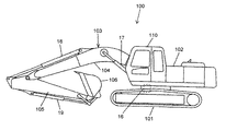
図1は、本発明の実施の形態に係る油圧駆動装置が搭載された油圧ショベルの側面図である。 FIG. 1 is a side view of a hydraulic excavator equipped with a hydraulic drive device according to an embodiment of the present invention.
図1において、油圧ショベル100は、走行体101、この走行体101上に旋回可能に取り付けられた旋回体102と、この旋回体102の前側に上下方向に回動可能に取り付けられた作業装置103とを備えている。旋回体102は、旋回モータ16によって駆動される。
In FIG. 1, the
作業装置103は、旋回体102の前側に上下方向に回動可能に取り付けられたブーム104と、このブーム104の先端部に上下または前後方向に回動可能に取り付けられたアーム105と、このアーム105の先端部に上下または前後方向に回動可能に取り付けられたバケット106とを備えている。ブーム104は、油圧アクチュエータであるブームシリンダ17によって駆動され、アーム105は油圧アクチュエータであるアームシリンダ18によって駆動され、バケット106は油圧アクチュエータであるバケットシリンダ19によって駆動される。旋回体102の前側には、オペレータが搭乗する運転室110が設けられている。
The
図2は、油圧ショベル100に搭載された油圧駆動装置の概略構成図である。
FIG. 2 is a schematic configuration diagram of a hydraulic drive device mounted on the
図2において、油圧駆動装置200は、エンジン(原動機)11により駆動される可変容量式の第1および第2油圧ポンプ12a,12bと、第1油圧ポンプ12aの吐出側にパラレル接続される複数の方向切換弁13aからなる第1方向切換弁ユニット14aと、第2油圧ポンプ12bの吐出側にパラレル接続される複数の方向切換弁13bからなる第2方向切換弁ユニット14bとを備えている。
In FIG. 2, the
第1方向切換弁ユニット14aを構成する複数の方向切換弁13a、および第2方向切換弁ユニット14bを構成する複数の方向切換弁13bはそれぞれ油圧アクチュエータに接続されている。そして、各方向切換弁13a,13bはパイロット方式(油圧式または電磁式)で切り換わるように構成されており、その切り換え操作は運転室110内に設けられた操作レバーや操作ペダル等の操作手段により行われる。また、第1および第2油圧ポンプ12a,12bからの圧油をタンク24にバイパスするバイパスラインには、第1および第2バイパスカット弁22a,22bが設けられている。第1および第2バイパスカット弁22a,22bは、コントローラ30(図4に示す)からの指令によって第1および第2油圧ポンプ12a,12bからタンク24にバイパスされる流量(以下、ブリードオフ流量)を制御する。
The plurality of
ここで、油圧ショベル100に設けられる油圧アクチュエータは、油圧モータからなる左右の走行モータ15R,15L及び旋回モータ16と、ブーム104を駆動するブームシリンダ17と、アーム105を駆動するアームシリンダ18と、バケット106を駆動するバケットシリンダ19とを含む。これら油圧アクチュエータのうち、ブームシリンダ17およびアームシリンダ18については、第1および第2油圧ポンプ12a,12bからの圧油を合流させて供給できるようにしている。なお、本実施例に係る油圧駆動装置200は2台の油圧ポンプ12a,12bを備えているが、油圧ポンプの数は作業負荷等に応じて適宜変更可能である。
Here, the hydraulic actuators provided in the
第1および第2油圧ポンプ12a,12bとタンク24との間には、油圧回路の最高圧力を規制するためのリリーフ弁25が設けられており、これにより油圧回路を構成する各部の保護が図られる。
A
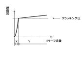
図3にリリーフ弁25のリリーフ特性を示す。
FIG. 3 shows the relief characteristics of the
図3において、横軸はリリーフ弁25からタンク24へ排出される流量(リリーフ流量)を示し、縦軸は回路圧を示している。領域Xは、リリーフ弁25への供給流量が十分でなく、リリーフ弁25からの漏れにより回路圧がリリーフ弁25のクラッキング圧(開放圧)に達していない状態を示す。これは回路圧がクラッキング圧に達する以前にリリーフ弁25から油が漏れることにより回路圧がクラッキング圧まで立たない(供給流量が足りない)ことを意味している。すなわち、リリーフ弁25にはある程度の漏れ流量が存在する。領域Yは、リリーフ弁25に十分な流量が供給されて回路圧がクラッキング圧に達し、リリーフ弁が開いた状態を示す(この時、リリーフ流量が増加するにつれて回路圧が僅かに上昇するが、この傾向をリリーフ弁のオーバライド特性と呼ぶ)。
In FIG. 3, the horizontal axis represents the flow rate (relief flow rate) discharged from the
第1および第2油圧ポンプ12a,12bの漏れ流量の測定は、第1および第2油圧ポンプ12a,12bに接続されている弁装置(第1および第2方向切換弁ユニット141,14b,リリーフ弁25等)からタンク24に油が漏れない状態で行うことが望ましい。しかし、第1および第2方向切換弁ユニット141,14bやリリーフ弁25では、スティックやゴミつまりが発生しないように、スプールとスプール穴との間、または弁体と弁座との間にクリアランス(隙間)が設けられており、漏れ流量をゼロにすることは困難である。特にリリーフ弁25の場合、回路圧が規定圧力に達したときに速やかに開弁できるという安全弁としての性質上、スムースかつ安定した動作が求められるため、クリアランスが大きめに設定されている。また、リリーフ弁25は、第1および第2油圧ポンプ12a,12bからの大流量をタンク24に排出できる必要があり、バルブサイズが大きくなるため、リリーフ弁25の漏れ流量を極小に抑えることは難しいのが現状である。
The leakage flow rate of the first and second
そこで、本実施の形態に係る油圧駆動装置200では、リリーフ弁25の漏れ流量を考慮することにより、第1および第2油圧ポンプ12a,12bの漏れ流量の正確な測定を可能としている。
Therefore, in the
図4に油圧駆動装置300の等価回路を示す。 FIG. 4 shows an equivalent circuit of the hydraulic drive device 300.
図4において、本実施の形態に係る油圧駆動装置200は、油圧源となる第1および第2油圧ポンプ12a,12bと、第1および第2油圧ポンプ12a,12bの吐出油をタンク24にバイパスする第1および第2バイパスカット弁22a,22bと、第1および第2油圧ポンプ12a,12bからの圧油の圧力を制限するリリーフ弁25とを備えている。リリーフ弁25は第1および第2油圧ポンプ12a,12bの各吐出圧Pp1,Pp2を制限するものであり、チェック弁を介して第1および第2吐出油路41a,41bに接続されている。さらに、第1および第2油圧ポンプ12a,12bの漏れ診断を行うために、第1および第2油圧ポンプ12a,12bの各吐出圧Pp1,Pp2をそれぞれ検出する圧力センサ26a,26bと、第1および第2油圧ポンプ12a,12bの押しのけ容積(傾転量)を調整するためのレギュレータ20a,20bと、エンジン11の回転数(以下、エンジン回転数)を制御すると共に、各機器の状態量と圧力センサ26a,26bからの信号を基に第1および第2油圧ポンプ12a,12bの漏れ流量を算出するコントローラ30と、コントローラ30が算出した漏れ流量を表示する表示装置31とを備えている。
In FIG. 4, the
図4において、油圧駆動装置300の各部の流量は以下の通りである。 In FIG. 4, the flow rate of each part of the hydraulic drive device 300 is as follows.
QBL1:第1油圧ポンプ12aのブリードオフ流量
QBL2:第2油圧ポンプ12bのブリードオフ流量
QP1Leak:第1油圧ポンプ12aの漏れ流量
QP2Leak:第2油圧ポンプ12bの漏れ流量
Qrelief:リリーフ流量
QP1ref:第1油圧ポンプの理論吐出流量(第1ポンプ理論流量)
QP2ref:第2油圧ポンプの理論吐出流量(第2ポンプ理論流量)
ここで、ポンプ理論流量QP1ref,QP2refは下記の式で求められる。
QBL1: Bleed-off flow rate of the first
QP2ref: Theoretical discharge flow rate of the second hydraulic pump (theoretical flow rate of the second pump)
Here, the pump theoretical flow rates QP1ref and QP2ref are calculated by the following equations.
QP1ref = qp1 × Neng
QP2ref = qp2 × Neng
qp1:第1油圧ポンプ12aのポンプ押しのけ容積(傾転量)
qp2:第2油圧ポンプ12bのポンプ押しのけ容積(傾転量)
Neng:エンジン回転数(ポンプ回転数)
コントローラ30は、第1および第2油圧ポンプ12a,12bの診断指令を受けて、第1および第2油圧ポンプ12a,12bの漏れ流量QP1Leak,QP2Leakを算出する。この診断指令は、オペレータの指示により発生させても良いし、油圧ショベル100が診断に適した状態となったときに自動的に発生させても良い。
QP1ref = qp1 x Neng
QP2ref = qp2 x Neng
qp1: Pump push-out volume (tilt amount) of the first
qp2: Pump push-out volume (tilt amount) of the second
Neng: Engine speed (pump speed)
The
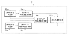
図5にコントローラ30の機能ブロック図を示す。
FIG. 5 shows a functional block diagram of the
図5において、コントローラ30は、第1吐出圧判定部30aと、第2吐出圧判定部30bと、第1ポンプ理論流量保持部30cと、第2ポンプ理論流量保持部30dと、合計ポンプ理論流量保持部30eと、漏れ流量算出部30fとを有する。
In FIG. 5, the
第1吐出圧判定部30aは、第1油圧ポンプ12aの吐出圧Pp1が規定圧力Pthに達したか否かを判定する。
The first discharge pressure determination unit 30a determines whether or not the discharge pressure Pp1 of the first
第2吐出圧判定部30bは、第2油圧ポンプ12bの吐出圧Pp2が規定圧力Pthに達したか否かを判定する。
The second discharge
第1ポンプ理論流量保持部30cは、第1油圧ポンプ12aの吐出圧Pp1が規定圧力Pth以上の場合に、第1油圧ポンプ12aの吐出流量を第1ポンプ理論流量QP1refとして保持する。
The first pump theoretical flow rate holding unit 30c holds the discharge flow rate of the first
第2ポンプ理論流量保持部30dは、第2油圧ポンプ12bの吐出圧Pp2が規定圧力Pth以上の場合に、第2油圧ポンプ12bの吐出流量を第2ポンプ理論流量QP2refとして保持する。
The second pump theoretical flow
合計ポンプ理論流量保持部eは、第1および第2油圧ポンプ12a,12bの各吐出圧Pp1,Pp2が規定圧力Pthに達したときの第1および第2油圧ポンプ12a,12bの合計吐出流量を合計ポンプ理論流量QP12refとして保持する。
The total pump theoretical flow rate holding unit e determines the total discharge flow rate of the first and second
漏れ流量算出部30fは、後述する式(1)〜(3)を連立して解くことにより、第1および第2油圧ポンプ12a,12bの各漏れ流量QP1Leak,QP2Leakを算出する。
The leak flow
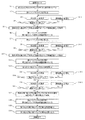
図6にコントローラ30の演算処理フローを示す。以下、当該フローを構成する各ステップについて順に説明する。
FIG. 6 shows the arithmetic processing flow of the
ステップS1にて、第1および第2油圧ポンプ12a,12bの各流量指令値を最小流量に設定する。これにより、第1および第2油圧ポンプ12a,12bの各吐出圧Pp1,Pp2が低下すると共に各吐出流量が最小となり、第1および第2油圧ポンプ12a,12bは小動力で運転される状態(スタンバイ状態)となる。
In step S1, each flow rate command value of the first and second
ステップS2にて、第1バイパスカット弁22aを閉じる。これにより、第1排出油路42aが遮断され、第1油圧ポンプ12aのブリードオフ流量QBL1はゼロとなる。
In step S2, the first bypass cut
ステップS3にて、第1油圧ポンプ12aの吐出圧Pp1を測定する。
In step S3, the discharge pressure Pp1 of the first
ステップS4にて、第1油圧ポンプ12aの吐出圧Pp1が規定圧力Pth以上となったか否かを判定する。ここで、規定圧力Pthはリリーフ設定圧(例えば35MPa)以下で比較的高い圧力(例えば30MPa)が望ましい。それにより、回路圧力が安定すると共に、油圧ポンプ内の小さな隙間から漏れる流量も大きくなるため、診断精度を向上させることができる。
In step S4, it is determined whether or not the discharge pressure Pp1 of the first
ステップS4でNo(第1油圧ポンプ12aの吐出圧Pp1が規定圧力Pth未満である)と判定した場合は、ステップS4−1へ進み、第1油圧ポンプ12aの傾転量qp1を微小量だけ増加させ、ステップS3へ戻る。このループを繰り返すことにより、第1油圧ポンプ12aの吐出圧Pp1が規定圧力Pthまで上昇する。
If it is determined in step S4 that No (the discharge pressure Pp1 of the first
ステップS4でYes(第1油圧ポンプ12aの吐出圧Pp1が規定圧力Pth以上である)と判定した場合は、ステップS5へ進む。
If it is determined in step S4 that Yes (the discharge pressure Pp1 of the first
ステップS5にて、現在(すなわち、第1油圧ポンプ12aの吐出圧Pp1が規定圧力Pthに達したとき)の第1油圧ポンプ12aの吐出流量を第1ポンプ理論流量QP1refとして保持する。
In step S5, the current discharge flow rate of the first
ステップS6にて、第1バイパスカット弁22aを開くとともに、第1油圧ポンプ12aの吐出流量を最小とし、第1油圧ポンプ12aをスタンバイ状態に戻す。
In step S6, the first bypass cut
ステップS7にて、第2バイパスカット弁22bを閉じる。これにより、第2排出油路42bが遮断され、第2油圧ポンプ12bのブリードオフ流量QBL2はゼロとなる。
In step S7, the second bypass cut
ステップS8にて、第2油圧ポンプ12bの吐出圧Pp2を測定する。
In step S8, the discharge pressure Pp2 of the second
ステップS9にて、第2油圧ポンプ12bの吐出圧Pp2が規定圧力Pth以上となったか否かを判定する。
In step S9, it is determined whether or not the discharge pressure Pp2 of the second
ステップS9でNo(第2油圧ポンプ12bの吐出圧Pp2が規定圧力Pth未満である)と判定した場合は、ステップS9−1へ進み、第2油圧ポンプ12bの傾転量qp2を微小量だけ増加させ、ステップS8へ戻る。このループを繰り返すことにより、第2油圧ポンプ12bの吐出圧Pp2が規定圧力Pthまで上昇する。
If it is determined in step S9 that No (the discharge pressure Pp2 of the second
ステップS9でYes(第2油圧ポンプ12bの吐出圧Pp2が規定圧力Pth以上である)と判定した場合は、ステップS10へ進む。
If it is determined in step S9 that Yes (the discharge pressure Pp2 of the second
ステップS10にて、第2油圧ポンプ12bの現在(すなわち、第2油圧ポンプ12bの吐出圧Pp2が規定圧力Pthに達したとき)の吐出流量を第2ポンプ理論流量QP2refとして保持する。
In step S10, the current discharge flow rate of the second
ステップS11にて、第2バイパスカット弁22bを開くとともに、第2油圧ポンプ12bの吐出流量を最小とし、第2油圧ポンプ12bをスタンバイ状態に戻す。
In step S11, the second bypass cut
ステップS12にて、第1および第2バイパスカット弁22a,22bを閉じる。これにより、第1および第2排出油路42a,42bが遮断され、第1および第2油圧ポンプ12a,12bの各ブリードオフ流量QBL1,QBL2はゼロとなる。
In step S12, the first and second
ステップS13にて、第1油圧ポンプ12aの吐出圧Pp1を測定する。
In step S13, the discharge pressure Pp1 of the first
ステップS14にて、第1油圧ポンプ12aの吐出圧Pp1が規定圧力Pth以上となったか否かを判定する。
In step S14, it is determined whether or not the discharge pressure Pp1 of the first
ステップS14でNo(第1油圧ポンプ12aの吐出圧Pp1が規定圧力Pth未満である)と判定した場合は、ステップS14−1へ進み、第1油圧ポンプ12aの傾転量qp1を微小量だけ増加させ、ステップS13へ戻る。このループを繰り返すことにより、第1油圧ポンプ12aの吐出圧Pp1が規定圧力Pthまで上昇する。
If it is determined in step S14 that No (the discharge pressure Pp1 of the first
ステップS14でYes(第1油圧ポンプ12aの吐出圧Pp1が規定圧力Pth以上である)と判定した場合は、ステップS15へ進む。
If it is determined in step S14 that Yes (the discharge pressure Pp1 of the first
ステップS15にて、第2油圧ポンプ12bの吐出圧Pp2を測定する。
In step S15, the discharge pressure Pp2 of the second
ステップS16にて、第2油圧ポンプ12bの吐出圧Pp2が規定圧力Pth以上となったか否かを判定する。
In step S16, it is determined whether or not the discharge pressure Pp2 of the second
ステップS16でNo(第2油圧ポンプ12bの吐出圧Pp2が規定圧力Pth未満である)と判定した場合は、ステップS16−1へ進み、第2油圧ポンプ12bの傾転量qp2を微小量だけ増加させ、ステップS15へ戻る。このループを繰り返すことにより、第2油圧ポンプ12bの吐出圧Pp2が規定圧力Pthまで上昇する。
If it is determined in step S16 that No (the discharge pressure Pp2 of the second
ステップS16でYes(第2油圧ポンプ12bの吐出圧Pp2が規定圧力Pth以上である)と判定した場合は、ステップS17へ進む。
If it is determined in step S16 that Yes (the discharge pressure Pp2 of the second
ステップS17にて、現在の第1および第2油圧ポンプ12a,12bの合計吐出流量を合計ポンプ理論流量QP12refとして保持する。
In step S17, the current total discharge flow rates of the first and second
ステップS18にて、第1および第2バイパスカット弁22a,22bを開くとともに、第1および第2油圧ポンプ12a,12bの吐出流量を最小とする。これにより、第1および第2油圧ポンプ12a,12bはスタンバイ状態に戻る。
In step S18, the first and second
ステップS19にて、ステップS5で保持した第1ポンプ理論流量QP1ref、ステップS10で保持した第2ポンプ理論流量QP2ref、およびステップS17で保持した合計ポンプ理論流量QP12refを基に、第1油圧ポンプ12aの漏れ流量QP1Leak、および第2油圧ポンプ12bの漏れ流量QP2Leakを算出する。具体的な算出方法を以下に示す。
In step S19, the first
第1油圧ポンプ12aの吐出圧Pp1が規定圧力Pthに達したとき(ステップS4でYesと判定した直後)の流量収支は以下の式で表される。
The flow rate balance when the discharge pressure Pp1 of the first
QP1Leak + Qrelief = QP1ref ・・・(1)
第2油圧ポンプ12bの吐出圧Pp2が規定圧力Pthに達したとき(ステップS9でYesと判定した直後)の流量収支は以下の式で表される。
QP1Leak + QLelief = QP1ref ... (1)
The flow rate balance when the discharge pressure Pp2 of the second
QP1Leak + Qrelief = QP1ref ・・・(2)
第1油圧ポンプ12aおよび第2油圧ポンプ12bの各吐出圧Pp1,Pp2が規定圧力Pthに達したとき(ステップS16でYesと判定した直後)の流量収支は以下の式で表される。
QP1Leak + QUIref = QP1ref ... (2)
The flow rate balance when the discharge pressures Pp1 and Pp2 of the first
QP1Leak + QP2Leak + Qrelief = QP12ref ・・・・(3)
上記式(1),(2),(3)に、ステップS5で保持した第1ポンプ理論流量QP1ref、ステップS10で保持した第2ポンプ理論流量QP2ref、およびステップS17で保持した合計ポンプ理論流量QP12refを代入して解くことにより、第1油圧ポンプ12aおよび第2油圧ポンプ12bの漏れ流量QP1Leak、QP2Leak、およびリリーフ弁25の漏れ流量Qreliefが求まる。
QP1Leak + QP2Leak + QUIref = QP12ref ... (3)
In the above equations (1), (2), and (3), the first pump theoretical flow rate QP1ref held in step S5, the second pump theoretical flow rate QP2ref held in step S10, and the total pump theoretical flow rate QP12ref held in step S17. By substituting and solving, the leakage flow rates QP1Leak and QP2Leak of the first
ステップS20にて、第1および第2油圧ポンプ12a,12bの漏れ流量値を表示装置31へ出力し、当該フローを終了する。これにより、運転室110のオペレータは、第1および第2油圧ポンプ12a,12bの漏れ流量QP1Leak,QP2Leakを把握することができる。
In step S20, the leakage flow rate values of the first and second
ここで計算例として、第1ポンプ理論流量QP1ref、第2ポンプ理論流量QP2ref、および合計ポンプ理論流量QP12refに具体的な値を代入し、第1および第2油圧ポンプ12a,12bの漏れ流量QP1Leak,QP2Leak、およびリリーフ漏れ流量QRLeakを求めてみる。第1ポンプ理論流量QP1ref、第2ポンプ理論流量QP2ref、および合計ポンプ理論流量QP12refを、
QP1ref = 40(L/min)
QP2ref = 30(L/min)
QP12ref = 60(L/min)
とすると、式(1),(2),(3)は、
QP1Leak + Qrelief = 40 ・・・(1)’
QP2Leak + Qrelief = 30 ・・・(2)’
QP1Leak + QP2Leak + Qrelief = 60 ・・・(3)’
となり、上記式(1)’,(2)’,(3)’を連立して解くと、
Qrelief = 10(L/min)
QP1Leak = 30(L/min)
QP2Leak = 20(L/min)
と求まる。
Here, as a calculation example, specific values are substituted for the first pump theoretical flow rate QP1ref, the second pump theoretical flow rate QP2ref, and the total pump theoretical flow rate QP12ref, and the leakage flow rates QP1Leak of the first and second
QP1ref = 40 (L / min)
QP2ref = 30 (L / min)
QP12ref = 60 (L / min)
Then, the equations (1), (2), and (3) are
QP1Leak + QRelief = 40 ・ ・ ・ (1)'
QP2Leak + QRelief = 30 ・ ・ ・ (2)'
QP1Leak + QP2Leak + Quelief = 60 ... (3)'
Then, when the above equations (1)', (2)', and (3)' are solved simultaneously,
Qrelief = 10 (L / min)
QP1Leak = 30 (L / min)
QP2Leak = 20 (L / min)
Is sought.
本実施例では、原動機11と、作動油を貯留するタンク24と、原動機11によって駆動され、タンク24から吸い込んだ作動油を圧油として吐出する可変容量型の第1油圧ポンプ12aおよび第2油圧ポンプ12bと、複数の油圧アクチュエータ15L,15R,16,17,18,19と、第1油圧ポンプ12aの吐出油が供給される第1吐出油路41aに接続され、第1油圧ポンプ12aから複数の油圧アクチュエータ15L,15R,16,17,18,19の少なくとも一部(油圧アクチュエータ15R,16,18)に供給される圧油の流れを制御する第1方向切換弁ユニット14aと、第2油圧ポンプ12bの吐出油が供給される第2吐出油路41bに接続され、第2油圧ポンプ12bから複数の油圧アクチュエータ15L,15R,16,17,18,19の少なくとも一部(油圧アクチュエータ15L,17,19)に供給される圧油の流れを制御する第2方向切換弁ユニット14bと、第1吐出油路41aおよび第2吐出油路41bとタンク24との間に設けられたリリーフ弁25と、原動機11の回転数と第1油圧ポンプ12aおよび第2油圧ポンプ12bの各傾転量を制御するコントローラ30とを備えた油圧駆動装置200において、第1油圧ポンプ12aの吐出圧Pp1を検出する第1圧力検出装置26aと、第2油圧ポンプ12bの吐出圧Pp2を検出する第2圧力検出装置26bとを備え、コントローラ30は、第2油圧ポンプ12bの傾転量を最小傾転量に保持した状態で、第1油圧ポンプ12aの傾転量を最小傾転量から増加させ、第1油圧ポンプ12aの吐出圧Pp1が前記リリーフ弁のクラッキング圧よりも低く設定された規定圧力Pthに達したときの第1油圧ポンプ12aの吐出流量を第1ポンプ理論流量QP1refとして保持し、第1油圧ポンプ12aの傾転量を最小傾転量に保持した状態で、第2油圧ポンプ12bの傾転量を最小傾転量から増加させ、第2油圧ポンプ12bの吐出圧Pp2が規定圧力Pthに達したときの第2油圧ポンプ12bの吐出流量を第2ポンプ理論流量QP2refとして保持し、第1油圧ポンプ12aおよび第2油圧ポンプ12bの各ポンプ傾転量を最小傾転量から増加させ、第1油圧ポンプ12aおよび第2油圧ポンプ12bの各吐出圧Pp1,Pp2が規定圧力Pthに達したときの第1および第2油圧ポンプ12a,12bの合計吐出流量を合計ポンプ理論流量QP12refとして保持し、第1ポンプ理論流量QP1ref、第2ポンプ理論流量QP2ref、および合計ポンプ理論流量QP12refに基づいて、第1油圧ポンプ12aおよび第2油圧ポンプ12bの漏れ流量QP1Leak,QP2Leakを算出することにより、第1油圧ポンプ12aおよび第2油圧ポンプ12bの漏れ診断を行う。
In this embodiment, the
以上のように構成した本実施例に係る油圧駆動装置200によれば、第1油圧ポンプ12aの吐出圧Pp1がリリーフ設定圧よりも低く設定された規定圧力Pthに達したときの第1油圧ポンプ12aの吐出流量(第1ポンプ理論流量QP1ref)、第2油圧ポンプ12bの吐出圧Pp2が規定圧力Pthに達したときの第2油圧ポンプ12bの吐出流量(第2ポンプ理論流量QP2ref)、および第1および第2油圧ポンプ12a,12bの各吐出圧Pp1,Pp2が規定圧力Pthに達したときの第1および第2油圧ポンプ12a,12bの合計吐出流量(合計ポンプ理論流量QP12ref)に基づいて、第1および第2油圧ポンプ12a,12bの各漏れ流量QP1Leak,QP2Leakを算出することにより、リリーフ弁25の漏れ流量Qreliefの大小にかかわらず、第1および第2油圧ポンプ12a,12bの各漏れ流量QP1Leak,QP2Leakを正確に測定することが可能となる。
According to the
また、油圧駆動装置200は、第1方向切換弁ユニット14aとタンク24とを接続する第1排出油路42aに設けられ、コントローラ30からの制御信号に応じて、第1排出油路42aを連通する連通位置および第1排出油路42aを遮断する遮断位置のいずれかに切換可能な第1バイパスカット弁22aと、第2方向切換弁ユニット14bとタンク24とを接続する第2排出油路42bに設けられ、コントローラ50からの制御信号に応じて、第2排出油路42bを連通する連通位置および第2排出油路42bを遮断する遮断位置のいずれかに切換可能な第2バイパスカット弁22bとを更に備え、コントローラ30は、第1油圧ポンプ12aおよび第2油圧ポンプ12bの漏れ診断を行う際に、第1バイパスカット弁22aおよび第2バイパスカット弁22bをそれぞれ遮断位置に切り換える制御信号を出力する。
Further, the
これにより、方向切換弁13a,13bを全て中立位置に保持した状態(すなわち、油圧アクチュエータ15L,15R,16,17,18,19に圧油が供給されない状態)で、第1および第2油圧ポンプ12a,12bの漏れ診断を行うことが可能となり、第1および第2油圧ポンプ12a,12bの漏れ診断中に油圧ショベル100の意図しない動作を防止することが可能となる。
As a result, the first and second hydraulic pumps are in a state where all the
なお、本実施の形態においては、第1および第2油圧ポンプ12a,12bのブリードオフ流量QBL1,QBL2をゼロするのに第1および第2バイパスカット弁22a,22bを用いたが、ブリードオフ流量QBL1,QBL2をゼロにするための手段はこれらに限られない。例えば第2バイパスカット弁22bを設けない場合は、バケットシリンダ19用の方向切換弁13bを切り換え、バケットシリンダ19がストロークエンドに達した状態とすることにより、第2油圧ポンプ12bのブリードオフ流量QBL2をゼロにすることができる。一方、第1油圧ポンプ12a側の第1バイパスカット弁22aを設けない場合は、旋回モータ16用の方向切換弁13aを利用する。油圧ショベル100は、旋回停止中に旋回体102を停止保持するためのパーキングブレーキ(図示しない)を備えており、パーキングブレーキで旋回モータ16をロックした状態で旋回モータ16用の方向切換弁13aを切り換えることにより、第1油圧ポンプ12aのブリードオフ流量QBL1をセロにすることができる。
In the present embodiment, the first and second
また、図示は省略するが、油圧駆動装置200は、可変容量型の第3油圧ポンプと、前記第3油圧ポンプの吐出圧を検出する第3圧力検出装置とを更に備え、リリーフ弁25は、前記第3油圧ポンプの吐出油路とタンク24との間に設けられ、コントローラ30は、第1油圧ポンプ12aおよび第2油圧ポンプ12bの組合せに加えて、第1油圧ポンプ12aおよび第3油圧ポンプの組合せ、または第2油圧ポンプ12bおよび第3油圧ポンプの組合せに対して漏れ診断を行うように構成しても良い。
Although not shown, the
これにより、異なる油圧ポンプの組合せに対して漏れ診断が複数回行われるため、各油圧ポンプの漏れ流量の測定精度を確認することが可能となる。 As a result, the leak diagnosis is performed a plurality of times for the combination of different hydraulic pumps, so that it is possible to confirm the measurement accuracy of the leak flow rate of each hydraulic pump.
以上、本発明の実施例について詳述したが、本発明は、上述の実施例に限定されるものではなく、様々な変形例を含んでいる。例えば、上述の実施例では、油圧ショベルに搭載される油圧駆動装置に本発明を適用した場合を説明したが、クレーン等その他の作業機械に搭載される油圧駆動装置にも適用することができる。また、上述の実施例は、本発明を分かり易く説明するために詳細に説明したものであり、必ずしも説明した全ての構成を備えるものに限定されるものではない。 Although the examples of the present invention have been described in detail above, the present invention is not limited to the above-mentioned examples, and includes various modifications. For example, in the above-described embodiment, the case where the present invention is applied to a hydraulic drive device mounted on a hydraulic excavator has been described, but the present invention can also be applied to a hydraulic drive device mounted on other work machines such as cranes. Further, the above-described embodiment has been described in detail in order to explain the present invention in an easy-to-understand manner, and is not necessarily limited to the one including all the described configurations.
11…エンジン(原動機)、12a…第1油圧ポンプ、12b…第2油圧ポンプ、13a,13b…方向切換弁、14a…第1方向切換弁ユニット、14b…第2方向切換弁ユニット、15L…左走行モータ、15R…右走行モータ、16…旋回モータ、17…ブームシリンダ、18…アームシリンダ、19…バケットシリンダ、20a,20b…レギュレータ、22a…第1バイパスカット弁、22b…第2バイパスカット弁、24…タンク、25…リリーフ弁、26a…圧力センサ(第1圧力検出装置)、26b…圧力センサ(第2圧力検出装置)、30…コントローラ、30a…第1吐出圧判定部、30b…第2吐出圧判定部、30c…第1ポンプ理論流量保持部、30d…第2ポンプ理論流量保持部、30e…合計ポンプ理論流量保持部、30f…漏れ流量算出部、31…表示装置、41a…第1吐出油路、41b…第2吐出油路、42a…第1排出油路、42b…第2排出油路、100…油圧ショベル、200…油圧駆動装置。 11 ... Engine (motor), 12a ... 1st hydraulic pump, 12b ... 2nd hydraulic pump, 13a, 13b ... Direction switching valve, 14a ... 1st direction switching valve unit, 14b ... 2nd direction switching valve unit, 15L ... Left Traveling motor, 15R ... Right traveling motor, 16 ... Swing motor, 17 ... Boom cylinder, 18 ... Arm cylinder, 19 ... Bucket cylinder, 20a, 20b ... Regulator, 22a ... First bypass cut valve, 22b ... Second bypass cut valve , 24 ... Tank, 25 ... Relief valve, 26a ... Pressure sensor (first pressure detection device), 26b ... Pressure sensor (second pressure detection device), 30 ... Controller, 30a ... First discharge pressure determination unit, 30b ... First 2 Discharge pressure determination unit, 30c ... 1st pump theoretical flow rate holding unit, 30d ... 2nd pump theoretical flow rate holding unit, 30e ... Total pump theoretical flow rate holding unit, 30f ... Leakage flow rate calculation unit, 31 ... Display device, 41a ... 1 Discharge oil passage, 41b ... 2nd discharge oil passage, 42a ... 1st discharge oil passage, 42b ... 2nd discharge oil passage, 100 ... Hydraulic excavator, 200 ... Hydraulic drive device.
Claims (3)
作動油を貯留するタンクと、
前記原動機によって駆動され、前記タンクから吸い込んだ作動油を圧油として吐出する可変容量型の第1油圧ポンプおよび第2油圧ポンプと、
複数の油圧アクチュエータと、
前記第1油圧ポンプの吐出油が供給される第1吐出油路に接続され、前記第1油圧ポンプから前記複数の油圧アクチュエータの少なくとも一部に供給される圧油の流れを制御する第1方向切換弁ユニットと、
前記第2油圧ポンプの吐出油が供給される第2吐出油路に接続され、前記第2油圧ポンプから前記複数の油圧アクチュエータの少なくとも一部に供給される圧油の流れを制御する第2方向切換弁ユニットと、
前記第1吐出油路および前記第2吐出油路と前記タンクとの間に設けられたリリーフ弁と、
前記原動機の回転数と前記第1油圧ポンプおよび前記第2油圧ポンプの各傾転量を制御するコントローラとを備えた油圧駆動装置において、
前記第1油圧ポンプの吐出圧を検出する第1圧力検出装置と、
前記第2油圧ポンプの吐出圧を検出する第2圧力検出装置とを備え、
前記コントローラは、
前記第2油圧ポンプの傾転量を最小傾転量に保持した状態で、前記第1油圧ポンプの傾転量を最小傾転量から増加させ、前記第1油圧ポンプの吐出圧が前記リリーフ弁のクラッキング圧よりも低く設定された規定圧力に達したときの前記第1油圧ポンプの吐出流量を第1ポンプ理論流量として保持し、
前記第1油圧ポンプの傾転量を最小傾転量に保持した状態で、前記第2油圧ポンプの傾転量を最小傾転量から増加させ、前記第2油圧ポンプの吐出圧が前記規定圧力に達したときの前記第2油圧ポンプの吐出流量を第2ポンプ理論流量として保持し、
前記第1油圧ポンプおよび前記第2油圧ポンプの各ポンプ傾転量を最小傾転量から増加させ、前記第1油圧ポンプおよび前記第2油圧ポンプの各吐出圧が前記規定圧力に達したときの前記第1油圧ポンプおよび前記第2油圧ポンプの合計吐出流量を合計ポンプ理論流量として保持し、
前記第1ポンプ理論流量、前記第2ポンプ理論流量、および前記合計ポンプ理論流量に基づいて、前記第1油圧ポンプおよび前記第2油圧ポンプの各漏れ流量を算出することにより、前記第1油圧ポンプおよび前記第2油圧ポンプの漏れ診断を行う
ことを特徴とする油圧駆動装置。 The prime mover and
A tank for storing hydraulic oil and
A variable-capacity first hydraulic pump and a second hydraulic pump that are driven by the prime mover and discharge the hydraulic oil sucked from the tank as pressure oil.
With multiple hydraulic actuators,
A first direction connected to a first discharge oil passage to which the discharge oil of the first hydraulic pump is supplied and controlling the flow of pressure oil supplied from the first hydraulic pump to at least a part of the plurality of hydraulic actuators. Switching valve unit and
A second direction connected to a second discharge oil passage to which the discharge oil of the second hydraulic pump is supplied and controlling the flow of pressure oil supplied from the second hydraulic pump to at least a part of the plurality of hydraulic actuators. Switching valve unit and
A relief valve provided between the first discharge oil passage and the second discharge oil passage and the tank, and
In a hydraulic drive system including a rotation speed of the prime mover and a controller for controlling each tilt amount of the first hydraulic pump and the second hydraulic pump.
A first pressure detection device that detects the discharge pressure of the first hydraulic pump, and
A second pressure detecting device for detecting the discharge pressure of the second hydraulic pump is provided.
The controller
While the tilt amount of the second hydraulic pump is held at the minimum tilt amount, the tilt amount of the first hydraulic pump is increased from the minimum tilt amount, and the discharge pressure of the first hydraulic pump is the relief valve. The discharge flow rate of the first hydraulic pump when the specified pressure set lower than the cracking pressure of the first hydraulic pump is reached is held as the first pump theoretical flow rate.
While the tilt amount of the first hydraulic pump is held at the minimum tilt amount, the tilt amount of the second hydraulic pump is increased from the minimum tilt amount, and the discharge pressure of the second hydraulic pump is the specified pressure. The discharge flow rate of the second hydraulic pump when it reaches is held as the second pump theoretical flow rate,
When the tilt amount of each of the first hydraulic pump and the second hydraulic pump is increased from the minimum tilt amount, and the discharge pressures of the first hydraulic pump and the second hydraulic pump reach the specified pressure. The total discharge flow rate of the first hydraulic pump and the second hydraulic pump is held as the total pump theoretical flow rate.
The first hydraulic pump by calculating each leakage flow rate of the first hydraulic pump and the second hydraulic pump based on the first pump theoretical flow rate, the second pump theoretical flow rate, and the total pump theoretical flow rate. And a hydraulic drive device for performing a leak diagnosis of the second hydraulic pump.
前記第1方向切換弁ユニットと前記タンクとを接続する第1排出油路に設けられ、前記コントローラからの制御信号に応じて、前記第1排出油路を連通する連通位置および前記第1排出油路を遮断する遮断位置のいずれかに切換可能な第1バイパスカット弁と、
前記第2方向切換弁ユニットと前記タンクとを接続する第2排出油路に設けられ、前記コントローラからの制御信号に応じて、前記第2排出油路を連通する連通位置および前記第2排出油路を遮断する遮断位置のいずれかに切換可能な第2バイパスカット弁とを更に備え、
前記コントローラは、前記第1油圧ポンプおよび前記第2油圧ポンプの漏れ診断を行う際に、前記第1バイパスカット弁および前記第2バイパスカット弁をそれぞれ遮断位置に切り換える制御信号を出力する
ことを特徴とする油圧駆動装置。 In the hydraulic drive device according to claim 1,
A communication position provided in the first drainage passage connecting the first direction switching valve unit and the tank, and a communication position communicating with the first drainage passage and the first drainage oil according to a control signal from the controller. A first bypass cut valve that can be switched to any of the shutoff positions that shut off the road,
A communication position provided in the second drainage passage connecting the second direction switching valve unit and the tank, and a communication position for communicating with the second drainage passage and the second drainage oil according to a control signal from the controller. Further provided with a second bypass cut valve that can be switched to any of the shutoff positions that shut off the road.
The controller is characterized in that when performing a leak diagnosis of the first hydraulic pump and the second hydraulic pump, it outputs a control signal for switching the first bypass cut valve and the second bypass cut valve to the cutoff position, respectively. Hydraulic drive device.
可変容量型の第3油圧ポンプと、
前記第3油圧ポンプの吐出圧を検出する第3圧力検出装置とを更に備え、
前記リリーフ弁は、前記第3油圧ポンプの吐出油路と前記タンクとの間に設けられ、
前記コントローラは、前記第1油圧ポンプおよび前記第2油圧ポンプの組合せに加えて、前記第1油圧ポンプおよび前記第3油圧ポンプの組合せ、または前記第2油圧ポンプおよび前記第3油圧ポンプの組合せに対して漏れ診断を行う
ことを特徴とする油圧駆動装置。 In the hydraulic drive device according to claim 1,
Variable capacity type third hydraulic pump and
A third pressure detecting device for detecting the discharge pressure of the third hydraulic pump is further provided.
The relief valve is provided between the discharge oil passage of the third hydraulic pump and the tank.
Said controller, said first addition to the combination of the hydraulic pump and the second hydraulic pump, the first hydraulic pump and a combination of the third hydraulic pump or a combination of the second hydraulic pump and the third hydraulic pump, A hydraulic drive that is characterized by performing leak diagnosis.
Priority Applications (1)
| Application Number | Priority Date | Filing Date | Title |
|---|---|---|---|
| JP2018145567A JP6901441B2 (en) | 2018-08-02 | 2018-08-02 | Hydraulic drive |
Applications Claiming Priority (1)
| Application Number | Priority Date | Filing Date | Title |
|---|---|---|---|
| JP2018145567A JP6901441B2 (en) | 2018-08-02 | 2018-08-02 | Hydraulic drive |
Publications (3)
| Publication Number | Publication Date |
|---|---|
| JP2020020421A JP2020020421A (en) | 2020-02-06 |
| JP2020020421A5 JP2020020421A5 (en) | 2020-09-24 |
| JP6901441B2 true JP6901441B2 (en) | 2021-07-14 |
Family
ID=69589755
Family Applications (1)
| Application Number | Title | Priority Date | Filing Date |
|---|---|---|---|
| JP2018145567A Active JP6901441B2 (en) | 2018-08-02 | 2018-08-02 | Hydraulic drive |
Country Status (1)
| Country | Link |
|---|---|
| JP (1) | JP6901441B2 (en) |
Family Cites Families (3)
| Publication number | Priority date | Publication date | Assignee | Title |
|---|---|---|---|---|
| JPH0694868B2 (en) * | 1983-01-19 | 1994-11-24 | 日立建機株式会社 | Fault diagnosis device for hydraulic pump |
| JPH1054370A (en) * | 1996-08-12 | 1998-02-24 | Hitachi Constr Mach Co Ltd | Trouble diagnostic device for oil hydraulic pump in work machine |
| JP3850617B2 (en) * | 2000-02-28 | 2006-11-29 | 日立建機株式会社 | Hydraulic work machine pump monitoring device |
-
2018
- 2018-08-02 JP JP2018145567A patent/JP6901441B2/en active Active
Also Published As
| Publication number | Publication date |
|---|---|
| JP2020020421A (en) | 2020-02-06 |
Similar Documents
| Publication | Publication Date | Title |
|---|---|---|
| KR101973872B1 (en) | Hydraulic drive system for work machine | |
| JP5965502B1 (en) | Hydraulic drive system for construction machinery | |
| EP2716919A1 (en) | Rotary work machine | |
| EP2733362A1 (en) | Hydraulic actuator damping control system for construction machinery | |
| KR101832080B1 (en) | Control system of hybrid construction machine | |
| EP3106677A1 (en) | Hydraulic drive device for construction machine | |
| JP2016223563A (en) | Construction machine hydraulic control device | |
| CN108779790B (en) | Construction machine | |
| WO2016056334A1 (en) | Hydraulic control apparatus for construction equipment | |
| WO2019049435A1 (en) | Construction machine | |
| US9903393B2 (en) | Construction machine | |
| JP5651099B2 (en) | Plunger pump failure diagnosis device | |
| KR102514523B1 (en) | Hydraulic control apparatus and hydraulic control method for construction machine | |
| US9725878B2 (en) | Hybrid-type construction machine | |
| WO2020066098A1 (en) | Construction machine | |
| JP2016065637A (en) | Fault diagnosis system of control valve in hydraulic circuit | |
| WO2021124658A1 (en) | Construction machine | |
| JP6901441B2 (en) | Hydraulic drive | |
| US11162242B2 (en) | Slewing-type work machine | |
| CN111601933B (en) | Rotary hydraulic engineering machinery | |
| JP6982561B2 (en) | Construction machinery | |
| JP2001355257A (en) | Hydraulic device of back hoe | |
| JP7314979B2 (en) | Fan drive controller for construction machinery | |
| JP6013015B2 (en) | Hydraulic control device for construction machine and control method thereof | |
| WO2021070736A1 (en) | Construction machine |
Legal Events
| Date | Code | Title | Description |
|---|---|---|---|
| A521 | Written amendment |
Free format text: JAPANESE INTERMEDIATE CODE: A523 Effective date: 20200812 |
|
| A621 | Written request for application examination |
Free format text: JAPANESE INTERMEDIATE CODE: A621 Effective date: 20200812 |
|
| A977 | Report on retrieval |
Free format text: JAPANESE INTERMEDIATE CODE: A971007 Effective date: 20210519 |
|
| TRDD | Decision of grant or rejection written | ||
| A01 | Written decision to grant a patent or to grant a registration (utility model) |
Free format text: JAPANESE INTERMEDIATE CODE: A01 Effective date: 20210608 |
|
| A61 | First payment of annual fees (during grant procedure) |
Free format text: JAPANESE INTERMEDIATE CODE: A61 Effective date: 20210617 |
|
| R150 | Certificate of patent or registration of utility model |
Ref document number: 6901441 Country of ref document: JP Free format text: JAPANESE INTERMEDIATE CODE: R150 |