WO2020054619A1 - はんだ付け装置 - Google Patents
はんだ付け装置 Download PDFInfo
- Publication number
- WO2020054619A1 WO2020054619A1 PCT/JP2019/035220 JP2019035220W WO2020054619A1 WO 2020054619 A1 WO2020054619 A1 WO 2020054619A1 JP 2019035220 W JP2019035220 W JP 2019035220W WO 2020054619 A1 WO2020054619 A1 WO 2020054619A1
- Authority
- WO
- WIPO (PCT)
- Prior art keywords
- soldering
- sleeve
- hot air
- unit
- land
- Prior art date
- Legal status (The legal status is an assumption and is not a legal conclusion. Google has not performed a legal analysis and makes no representation as to the accuracy of the status listed.)
- Ceased
Links
Images


Classifications
-
- B—PERFORMING OPERATIONS; TRANSPORTING
- B23—MACHINE TOOLS; METAL-WORKING NOT OTHERWISE PROVIDED FOR
- B23K—SOLDERING OR UNSOLDERING; WELDING; CLADDING OR PLATING BY SOLDERING OR WELDING; CUTTING BY APPLYING HEAT LOCALLY, e.g. FLAME CUTTING; WORKING BY LASER BEAM
- B23K1/00—Soldering, e.g. brazing, or unsoldering
-
- B—PERFORMING OPERATIONS; TRANSPORTING
- B23—MACHINE TOOLS; METAL-WORKING NOT OTHERWISE PROVIDED FOR
- B23K—SOLDERING OR UNSOLDERING; WELDING; CLADDING OR PLATING BY SOLDERING OR WELDING; CUTTING BY APPLYING HEAT LOCALLY, e.g. FLAME CUTTING; WORKING BY LASER BEAM
- B23K3/00—Tools, devices, or special appurtenances for soldering, e.g. brazing, or unsoldering, not specially adapted for particular methods
-
- B—PERFORMING OPERATIONS; TRANSPORTING
- B23—MACHINE TOOLS; METAL-WORKING NOT OTHERWISE PROVIDED FOR
- B23K—SOLDERING OR UNSOLDERING; WELDING; CLADDING OR PLATING BY SOLDERING OR WELDING; CUTTING BY APPLYING HEAT LOCALLY, e.g. FLAME CUTTING; WORKING BY LASER BEAM
- B23K31/00—Processes relevant to this subclass, specially adapted for particular articles or purposes, but not covered by only one of the preceding main groups
- B23K31/02—Processes relevant to this subclass, specially adapted for particular articles or purposes, but not covered by only one of the preceding main groups relating to soldering or welding
-
- H—ELECTRICITY
- H05—ELECTRIC TECHNIQUES NOT OTHERWISE PROVIDED FOR
- H05K—PRINTED CIRCUITS; CASINGS OR CONSTRUCTIONAL DETAILS OF ELECTRIC APPARATUS; MANUFACTURE OF ASSEMBLAGES OF ELECTRICAL COMPONENTS
- H05K3/00—Apparatus or processes for manufacturing printed circuits
- H05K3/30—Assembling printed circuits with electric components, e.g. with resistor
- H05K3/32—Assembling printed circuits with electric components, e.g. with resistor electrically connecting electric components or wires to printed circuits
- H05K3/34—Assembling printed circuits with electric components, e.g. with resistor electrically connecting electric components or wires to printed circuits by soldering
Definitions
- the present disclosure relates to a soldering device.
- Patent Document 1 Japanese Patent Application Laid-Open Publication No. H11-163873 discloses a first means for attaching a temperature control chip or a temperature control cap to the tip of a cylindrical iron as a preheating means, and adjusting a distance between the cylindrical iron and an adjuster pin to radiant heat of the iron. And third means for supplying a heated gas into a cylindrical iron are disclosed.
- soldering the terminals of the electronic component in the lands provided in the through holes of the board it is necessary to locally heat the lands and terminals, which are the parts that need to be soldered, before performing the soldering.
- a soldering device that can be used.
- a soldering device is a device for soldering a terminal of an electronic component in a land provided in a through hole of a board, and locally performs localization of the land and the terminal before performing soldering.
- An auxiliary heat source is provided to heat the heat.
- FIG. 1 schematically illustrates a configuration example of the soldering apparatus according to the first embodiment, and is a diagram illustrating an example of a state at the time of performing auxiliary heating.
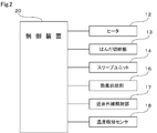
- FIG. 2 is a block diagram schematically illustrating a configuration example of a control system of the soldering apparatus according to the first embodiment
- FIG. 3 schematically illustrates a configuration example of the soldering apparatus according to the first embodiment, and is a diagram illustrating a state example when soldering is performed;
- FIG. 1 schematically illustrates a configuration example of the soldering apparatus according to the first embodiment, and is a diagram illustrating an example of a state at the time of performing auxiliary heating.
- FIG. 2 is a block diagram schematically illustrating a configuration example of a control system of the soldering apparatus according to the first embodiment
- FIG. 3 schematically illustrates a configuration example of the soldering apparatus according to the first embodiment, and is a diagram illustrating a state example when soldering is performed;
- FIG. 1 schematically illustrate
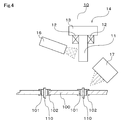
- FIG. 4 schematically illustrates a configuration example of a soldering apparatus according to a second embodiment, and is a diagram (part 1) illustrating a state example when auxiliary heating is performed
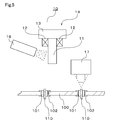
- FIG. 5 schematically illustrates a configuration example of the soldering apparatus according to the second embodiment, and is a diagram (part 2) illustrating a state example at the time of executing auxiliary heating
- FIG. 6 schematically illustrates a configuration example of the soldering apparatus according to the third embodiment, and is a diagram illustrating a state example at the time of executing auxiliary heating
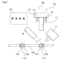
- FIG. 7 schematically illustrates a configuration example of the soldering apparatus according to the fourth embodiment, and is a diagram illustrating a state example when auxiliary heating is performed.
- a soldering apparatus 10 illustrated in FIG. 1 is an apparatus for soldering a terminal 110 of an electronic component in a land 102 provided in a through hole 101 of a substrate 100 such as a printed circuit board.
- the soldering device 10 is a so-called sleeve soldering device in which the solder is melted and soldered by the cylindrical sleeve 11.
- the soldering apparatus 10 includes a sleeve unit 14 having a sleeve 11, a heater 12, a solder cutting portion 13, and the like.
- the soldering apparatus 10 includes a sleeve unit 14 that can be moved vertically and horizontally with respect to the substrate 100.
- the sleeve 11 is made of, for example, ceramic or the like, and is formed in a vertically long cylindrical shape.
- the inside of the sleeve 11 is hollow.
- the heater 12 is provided, for example, on the upper outer surface of the sleeve 11 and heats the sleeve 11.
- the solder cutting section 13 cuts a thread-like solder supplied from a solder supply section (not shown) into a predetermined length by a cutter (not shown) to form a solder piece.
- the solder pieces formed by the solder cutting portions 13 fall into the sleeve 11 and are supplied.
- solder pieces supplied to the inside of the sleeve 11 are melted by coming into contact with the inner peripheral surface of the sleeve 11 being heated by the heater 12, whereby the electrons inserted into the lands 102 of the substrate 100 are melted.
- the terminals 110 of the component are soldered by the molten solder pieces.
- the soldering apparatus 10 includes a hot air supply unit 16 and a near infrared irradiation unit 17.
- the hot-air supply unit 16 is an example of an auxiliary heat source that locally heats the lands 102 and the terminals 110 of the electronic components in advance before soldering is performed by the sleeve unit 14.
- the hot air supply unit 16 includes a heater for heating air, a blower fan for blowing air heated by the heater, a fan motor for rotating the blower fan, and the like. It is configured to supply hot air by controlling the driving of the air.
- the hot air supply unit 16 is provided so as to be movable in the vertical and horizontal directions with respect to the substrate 100.
- the hot air supply unit 16 controls the rotation of a louver provided at the hot air outlet of the hot air supply unit 16 by, for example, the hot air supply unit 16 itself being rotatably provided. By doing so, the blowing direction of the hot air can be adjusted.
- the near-infrared irradiation unit 17 is an example of an auxiliary heat source that locally heats the lands 102 and the terminals 110 of the electronic components from a remote place before performing the soldering by the sleeve unit 14.
- the near-infrared irradiating section 17 includes a near-infrared heater that generates near-infrared rays, and is configured to emit near-infrared rays by controlling the driving of the near-infrared heater.
- the near-infrared ray irradiating unit 17 is provided so as to be movable in the vertical and horizontal directions with respect to the substrate 100.
- the near-infrared ray irradiating section 17 is provided so that the near-infrared ray irradiating direction can be adjusted by, for example, the near-infrared ray irradiating section 17 itself being rotatably provided.
- the control device 20 illustrated in FIG. 2 is mainly configured by, for example, a microcomputer, and drives the heater 12, the solder cutting unit 13, the sleeve unit 14, the hot air supply unit 16, the near-infrared irradiation unit.
- the entire operation of the soldering apparatus 10, such as the drive of 17, is controlled.
- the control device 20 is an example of a control unit.
- the control device 20 includes the temperature detection sensor 18 that detects the temperature of the land 102 and the terminal 110 of the electronic component, which are the parts that need to be soldered on the substrate 100.
- the temperature detection sensor 18 is configured by a so-called non-contact type temperature detection sensor that remotely detects the temperature of the temperature detection target.
- the control device 20 detects the heating temperature of the hot air supply unit 16 and the near-infrared ray irradiating unit 17 by the temperature detection sensor 18 and controls the drive, that is, the output of the hot air supply unit 16 and the near-infrared ray irradiating unit 17 based on the detected temperature. It is configured as follows.
- the control device 20 can adjust the heating temperature of the land 102 and the terminal 110 of the electronic component by the hot air supply unit 16 and the heating temperature of the land 102 and the terminal 110 of the electronic component by the near-infrared irradiation unit 17.
- the temperature detection sensor 18 may be configured as a so-called contact-type temperature detection sensor that detects a temperature by approaching or touching a temperature detection target.
- control device 20 specifies the movement position of the sleeve unit 14, that is, the movement position of the sleeve 11, based on, for example, fluctuation values of various parameters of a movement mechanism (not shown) for moving the sleeve unit 14. It is configured to be possible. As illustrated in FIG. 1, when the movement position of the sleeve 11 is at a separation position where the distal end of the sleeve 11 is separated from the upper surface of the substrate 100, the control device 20 controls the hot air supply unit 16 and the near infrared irradiation unit 17. Is configured to be driven.
- control device 20 auxiliary heats the land 102 and the terminal 110 of the electronic component in advance by the auxiliary heat source before performing the soldering by the sleeve unit 14.
- the separated position can be defined as a raised position where the sleeve 11 has risen from the substrate 100.
- the control device 20 controls the hot air supply unit 16 and the near infrared irradiation unit. 17 is stopped.
- the control device 20 is configured not to heat the lands 102 and the terminals 110 of the electronic components by the auxiliary heat source during the soldering by the sleeve unit 14.
- the contact position is a lowered position where the sleeve 11 is lowered to the substrate 100 side, and can be defined as an example of a soldering execution position at which soldering is performed.
- a plurality of types of auxiliary heat sources are used as auxiliary heat sources for locally heating the lands 102 and the terminals 110 of the electronic components remotely in advance before the soldering by the sleeve unit 14 is performed.
- a hot air supply unit 16 and a near-infrared irradiation unit 17 are provided.
- Pinpoint heating can be performed remotely and locally. Therefore, the temperature of the land 102 and the terminal 110 of the electronic component, which are parts requiring soldering, can be maintained at an appropriate temperature without lowering, and the quality of soldering can be improved.
- the soldering device 10 is configured as a so-called sleeve soldering device that heats and melts the solder supplied to the inside of the cylindrical sleeve 11 to solder the terminal 110 of the electronic component to the land 102. I have.
- This type of sleeve soldering apparatus is suitable for a case where soldering is locally performed at a pinpoint location on a portion requiring soldering.
- the soldering device 10 is configured to move the sleeve 11 of the movably provided sleeve unit 14 to a lowered position, which is an example of a soldering execution position, in response to the hot air supply unit 16 and the near-infrared irradiation unit 17. Stop driving.
- the sleeve soldering apparatus 10 the sleeve 11 is heated to a high temperature of, for example, 400 ° C. or more. Therefore, the sleeve 11 is further heated by the hot air supply unit 16 and the near-infrared irradiation unit 17 during soldering. If done, the temperature of the sleeve 11 becomes excessively high, which may adversely affect the quality of soldering.
- the overheating of the sleeve 11 can be avoided by stopping the driving of the hot air supply unit 16 and the near-infrared irradiation unit 17 in response to the movement of the sleeve 11 to the soldering execution position. It can be maintained well.
- the soldering apparatus 10 controls the driving of the hot air supply unit 16 and the near infrared irradiation unit 17 based on the heating temperature of the hot air supply unit 16 and the near infrared irradiation unit 17.
- soldering is performed in a state where the land 102 and the terminal 110 of the electronic component, which are parts requiring soldering, are excessively pre-heated, that is, in a state where the temperature is excessively high, for example,
- the melting of the solder may be sharp, which may adversely affect the performance of the soldering.
- the control device 20 heats the sleeve 11 by the hot air supply unit 16 and performs the near-infrared irradiation unit 17 on the land 102 and the electronic component in a stage before the soldering is performed.
- the terminal 110 is heated.
- the control device 20 stops the driving of the hot air supply unit 16 and the near infrared irradiation unit 17 in response to the movement of the sleeve 11 to the soldering execution position at which the soldering is executed.
- the sleeve 11 is made of ceramic, heating by hot air can be more efficiently performed than by near-infrared rays.
- the land 102 is made of metal, for example, copper, heating by near infrared rays can be more efficiently performed than by hot air.
- the soldering apparatus 10 is configured so that the sleeve 11 is auxiliary-heated by the hot air supply unit 16 and the land 102 and the terminal 110 of the electronic component are auxiliary-heated by the near-infrared irradiation unit 17. According to this configuration, the sleeve 11 and the land 102 can be efficiently auxiliary-heated by the appropriate heat sources.
- the control device 20 moves the sleeve 11 to a position displaced from above the land 102 and the terminal 110 of the electronic component at a stage before the soldering, and supplies hot air at that position.
- the sleeve 11 may be heated by the part 16.
- the land 102 and the terminal 110 of the electronic component can be heated by the near-infrared irradiating unit 17 from directly above, and the land 102 and the terminal 110 of the electronic component can be heated more efficiently.
- the soldering apparatus 10 further includes a hot air directional control unit 16A and a near-infrared directional control unit 17A.
- the hot air directional control unit 16A is configured by, for example, a louver rotatably provided, and the directional direction is adjusted so that the hot air supplied by the hot air supply unit 16 is supplied to the land 102 and the terminal 110 of the electronic component. Orient to.
- the adjustment of the directivity direction of the hot air directivity control unit 16A may be configured to be performed automatically by the control device 20, or may be configured to be performed manually by a user.
- the hot air direction control unit 16A is not limited to a louver, and various configurations such as a nozzle can be employed as long as the configuration can adjust the direction of hot air.
- the near-infrared directivity control unit 17A is formed of, for example, a reflector provided so as to adjust the tilt angle, and adjusts the tilt angle so that the near-infrared light emitted by the near-infrared irradiation unit 17 is landed. 102 and the terminal 110 of the electronic component.
- the adjustment of the inclination angle of the near-infrared directivity control unit 17A may be configured to be performed automatically by the control device 20, or may be configured to be performed manually by a user.
- the near-infrared directivity control unit 17A is not limited to a reflection plate, and employs various configurations such as a condenser lens, a polarizing prism, and a reflecting mirror as long as the configuration can adjust the directivity of near-infrared rays. be able to.
- the hot air supplied by the hot air supply unit 16 and the near-infrared rays emitted by the near-infrared ray irradiating unit 17 efficiently reach the lands 102 and the terminals 110 of the electronic components, which are the parts requiring soldering. Therefore, the auxiliary heating of the portion requiring soldering can be performed more efficiently.
- the soldering apparatus 10 is not limited to the configuration including both the hot air directional control unit 16A and the near-infrared directional control unit 17A, but may be configured to include any one.
- the soldering device 10 further includes an exhaust device 30 as an example of an exhaust unit.
- the exhaust device 30 is provided near the soldering device 10, and is connected to, for example, a duct connected to the outside of the room where the soldering device 10 is installed.
- the exhaust device 30 includes an exhaust fan, a fan motor for rotating the exhaust fan, and the like, and is configured to be able to exhaust air around the soldering device 10.
- the control device 20 exhausts air. It is configured to drive the device 30. Therefore, by driving the exhaust device 30, air heated by the auxiliary heat source is mainly discharged.
- the land 102 and the terminals 110 of the electronic components are heated by the surrounding air, in addition to the heating by the hot air supply unit 16 and the near infrared irradiation unit 17. As a result, the temperature may be excessively high.
- the soldering device 10 exhausts the air around the soldering device 10, in other words, the air heated by the hot air supply unit 16 and the near infrared irradiation unit 17. It was configured as follows. Therefore, it is possible to avoid that the air around the soldering device 10 becomes excessively high during the auxiliary heating, and it is possible to suppress overheating of a portion that needs to be soldered. It can be maintained well. Further, by appropriately supplying hot air from the hot air supply unit 16 to gasified solder flux, so-called fume, which volatilizes from the solder melted during soldering, or by appropriately controlling the exhaust operation by the exhaust device 30, It can be efficiently removed.
- the inside, the outer surface, or the peripheral portion of the soldering device 10 can be stain-proofed by efficiently exhausting the gas to the exhaust device 30.
- soldering device is not limited to the soldering devices 10 according to the above-described embodiments, and various changes and extensions can be made without departing from the gist.
- the soldering device may not be a sleeve soldering device. Can be applied.
- the soldering apparatus 10 makes the drive time of the hot-air supply unit 16 different from the drive time of the near-infrared irradiation unit 17, and makes the output of the hot-air supply unit 16 and the output of the near-infrared irradiation unit 17 different, for example.
- the driving mode of the hot-air supply unit 16 and the driving mode of the near-infrared irradiation unit 17 are mutually changed, for example, by making the angle of blowing the hot air by the hot-air supply unit 16 different from the irradiation angle of near-infrared light by the near-infrared irradiation unit 17. May be controlled.
- the auxiliary heat source is not limited to hot air or near-infrared rays, and various heat sources can be adopted as long as the heat source can auxiliary heat a portion requiring soldering.
Landscapes
- Engineering & Computer Science (AREA)
- Mechanical Engineering (AREA)
- Manufacturing & Machinery (AREA)
- Microelectronics & Electronic Packaging (AREA)
- Electric Connection Of Electric Components To Printed Circuits (AREA)
Applications Claiming Priority (2)
| Application Number | Priority Date | Filing Date | Title |
|---|---|---|---|
| JP2018168746A JP6958519B2 (ja) | 2018-09-10 | 2018-09-10 | はんだ付け装置 |
| JP2018-168746 | 2018-09-10 |
Publications (1)
| Publication Number | Publication Date |
|---|---|
| WO2020054619A1 true WO2020054619A1 (ja) | 2020-03-19 |
Family
ID=69778266
Family Applications (1)
| Application Number | Title | Priority Date | Filing Date |
|---|---|---|---|
| PCT/JP2019/035220 Ceased WO2020054619A1 (ja) | 2018-09-10 | 2019-09-06 | はんだ付け装置 |
Country Status (2)
| Country | Link |
|---|---|
| JP (1) | JP6958519B2 (enExample) |
| WO (1) | WO2020054619A1 (enExample) |
Cited By (1)
| Publication number | Priority date | Publication date | Assignee | Title |
|---|---|---|---|---|
| WO2024038112A1 (en) | 2022-08-17 | 2024-02-22 | Institut National de la Santé et de la Recherche Médicale | Improved anti-albumin nanobodies and their uses |
Citations (6)
| Publication number | Priority date | Publication date | Assignee | Title |
|---|---|---|---|---|
| JPS61156896A (ja) * | 1984-12-28 | 1986-07-16 | 三菱電機株式会社 | 半田付け方法 |
| JP2005322806A (ja) * | 2004-05-10 | 2005-11-17 | Koyo Seiko Co Ltd | 接合装置 |
| JP2007073661A (ja) * | 2005-09-06 | 2007-03-22 | Fujifilm Corp | レーザはんだ付け方法及びレーザはんだ付け装置 |
| JP2012134269A (ja) * | 2010-12-21 | 2012-07-12 | Ricoh Microelectronics Co Ltd | ハンダ除去方法及びその装置 |
| JP2014146630A (ja) * | 2013-01-28 | 2014-08-14 | Fuji Electric Co Ltd | 半導体装置の製造方法及びはんだごて |
| JP2018019029A (ja) * | 2016-07-29 | 2018-02-01 | 株式会社アンド | 半田処理装置 |
-
2018
- 2018-09-10 JP JP2018168746A patent/JP6958519B2/ja active Active
-
2019
- 2019-09-06 WO PCT/JP2019/035220 patent/WO2020054619A1/ja not_active Ceased
Patent Citations (6)
| Publication number | Priority date | Publication date | Assignee | Title |
|---|---|---|---|---|
| JPS61156896A (ja) * | 1984-12-28 | 1986-07-16 | 三菱電機株式会社 | 半田付け方法 |
| JP2005322806A (ja) * | 2004-05-10 | 2005-11-17 | Koyo Seiko Co Ltd | 接合装置 |
| JP2007073661A (ja) * | 2005-09-06 | 2007-03-22 | Fujifilm Corp | レーザはんだ付け方法及びレーザはんだ付け装置 |
| JP2012134269A (ja) * | 2010-12-21 | 2012-07-12 | Ricoh Microelectronics Co Ltd | ハンダ除去方法及びその装置 |
| JP2014146630A (ja) * | 2013-01-28 | 2014-08-14 | Fuji Electric Co Ltd | 半導体装置の製造方法及びはんだごて |
| JP2018019029A (ja) * | 2016-07-29 | 2018-02-01 | 株式会社アンド | 半田処理装置 |
Cited By (1)
| Publication number | Priority date | Publication date | Assignee | Title |
|---|---|---|---|---|
| WO2024038112A1 (en) | 2022-08-17 | 2024-02-22 | Institut National de la Santé et de la Recherche Médicale | Improved anti-albumin nanobodies and their uses |
Also Published As
| Publication number | Publication date |
|---|---|
| JP6958519B2 (ja) | 2021-11-02 |
| JP2020040084A (ja) | 2020-03-19 |
Similar Documents
| Publication | Publication Date | Title |
|---|---|---|
| US20220320811A1 (en) | Laser soldering method and device | |
| US6998572B2 (en) | Light energy processing device and method | |
| US6768083B2 (en) | Reflow soldering apparatus and method for selective infrared heating | |
| KR102047445B1 (ko) | 전자소자의 본딩 및 디본딩 장치 | |
| WO2020054619A1 (ja) | はんだ付け装置 | |
| JP7196479B2 (ja) | スリーブはんだ付け装置 | |
| JP2002164647A (ja) | リフローはんだ付け装置 | |
| CN1895013B (zh) | 双级预热器 | |
| JP2002239717A (ja) | 光ビーム加熱方法および装置 | |
| US5900106A (en) | Bonding apparatus | |
| US20240269778A1 (en) | Laser welding device | |
| JP2682507B2 (ja) | 自動半田付け用プリヒータ装置 | |
| JP2004330304A (ja) | ピークエネルギーを有するパルス変調型Nd−YAGレーザーを用いたべローズ溶接 | |
| JP4524377B2 (ja) | リフロー装置 | |
| KR101917859B1 (ko) | 공공의 발생을 방지하기 위한 리플로우 솔더링 방법 | |
| JP2015185768A (ja) | 半田付け装置 | |
| JP4149768B2 (ja) | リフロー装置、リフロー方法及びリフロー炉 | |
| JP7601429B2 (ja) | 加熱装置、それを用いたハンダ付け方法及び溶接方法 | |
| JP4499963B2 (ja) | リフロー装置 | |
| JP2020040084A5 (enExample) | ||
| JP2006289464A (ja) | レーザ加熱制御方法およびレーザ加熱装置 | |
| JP2004276098A (ja) | 加熱方法と加熱装置と半田付け方法と半田付け装置 | |
| JPH06198423A (ja) | 光を用いた半田付け方法および半田付け装置 | |
| JPH11145611A (ja) | プリント基板製造装置 | |
| JPH11204933A (ja) | はんだづけ方法及びはんだづけ装置 |
Legal Events
| Date | Code | Title | Description |
|---|---|---|---|
| 121 | Ep: the epo has been informed by wipo that ep was designated in this application |
Ref document number: 19859002 Country of ref document: EP Kind code of ref document: A1 |
|
| NENP | Non-entry into the national phase |
Ref country code: DE |
|
| 122 | Ep: pct application non-entry in european phase |
Ref document number: 19859002 Country of ref document: EP Kind code of ref document: A1 |