WO2020054026A1 - 構造物評価システム、構造物評価装置及び構造物評価方法 - Google Patents
構造物評価システム、構造物評価装置及び構造物評価方法 Download PDFInfo
- Publication number
- WO2020054026A1 WO2020054026A1 PCT/JP2018/034004 JP2018034004W WO2020054026A1 WO 2020054026 A1 WO2020054026 A1 WO 2020054026A1 JP 2018034004 W JP2018034004 W JP 2018034004W WO 2020054026 A1 WO2020054026 A1 WO 2020054026A1
- Authority
- WO
- WIPO (PCT)
- Prior art keywords
- elastic wave
- evaluation
- wave source
- unit
- sensor
- Prior art date
- Legal status (The legal status is an assumption and is not a legal conclusion. Google has not performed a legal analysis and makes no representation as to the accuracy of the status listed.)
- Ceased
Links
Images


Classifications
-
- G—PHYSICS
- G01—MEASURING; TESTING
- G01N—INVESTIGATING OR ANALYSING MATERIALS BY DETERMINING THEIR CHEMICAL OR PHYSICAL PROPERTIES
- G01N29/00—Investigating or analysing materials by the use of ultrasonic, sonic or infrasonic waves; Visualisation of the interior of objects by transmitting ultrasonic or sonic waves through the object
- G01N29/04—Analysing solids
- G01N29/07—Analysing solids by measuring propagation velocity or propagation time of acoustic waves
-
- G—PHYSICS
- G01—MEASURING; TESTING
- G01N—INVESTIGATING OR ANALYSING MATERIALS BY DETERMINING THEIR CHEMICAL OR PHYSICAL PROPERTIES
- G01N29/00—Investigating or analysing materials by the use of ultrasonic, sonic or infrasonic waves; Visualisation of the interior of objects by transmitting ultrasonic or sonic waves through the object
- G01N29/04—Analysing solids
- G01N29/043—Analysing solids in the interior, e.g. by shear waves
-
- G—PHYSICS
- G01—MEASURING; TESTING
- G01N—INVESTIGATING OR ANALYSING MATERIALS BY DETERMINING THEIR CHEMICAL OR PHYSICAL PROPERTIES
- G01N29/00—Investigating or analysing materials by the use of ultrasonic, sonic or infrasonic waves; Visualisation of the interior of objects by transmitting ultrasonic or sonic waves through the object
- G01N29/14—Investigating or analysing materials by the use of ultrasonic, sonic or infrasonic waves; Visualisation of the interior of objects by transmitting ultrasonic or sonic waves through the object using acoustic emission techniques
-
- G—PHYSICS
- G01—MEASURING; TESTING
- G01N—INVESTIGATING OR ANALYSING MATERIALS BY DETERMINING THEIR CHEMICAL OR PHYSICAL PROPERTIES
- G01N29/00—Investigating or analysing materials by the use of ultrasonic, sonic or infrasonic waves; Visualisation of the interior of objects by transmitting ultrasonic or sonic waves through the object
- G01N29/22—Details, e.g. general constructional or apparatus details
- G01N29/24—Probes
- G01N29/2437—Piezoelectric probes
-
- G—PHYSICS
- G01—MEASURING; TESTING
- G01N—INVESTIGATING OR ANALYSING MATERIALS BY DETERMINING THEIR CHEMICAL OR PHYSICAL PROPERTIES
- G01N29/00—Investigating or analysing materials by the use of ultrasonic, sonic or infrasonic waves; Visualisation of the interior of objects by transmitting ultrasonic or sonic waves through the object
- G01N29/44—Processing the detected response signal, e.g. electronic circuits specially adapted therefor
-
- G—PHYSICS
- G01—MEASURING; TESTING
- G01N—INVESTIGATING OR ANALYSING MATERIALS BY DETERMINING THEIR CHEMICAL OR PHYSICAL PROPERTIES
- G01N2291/00—Indexing codes associated with group G01N29/00
- G01N2291/02—Indexing codes associated with the analysed material
- G01N2291/023—Solids
- G01N2291/0232—Glass, ceramics, concrete or stone
-
- G—PHYSICS
- G01—MEASURING; TESTING
- G01N—INVESTIGATING OR ANALYSING MATERIALS BY DETERMINING THEIR CHEMICAL OR PHYSICAL PROPERTIES
- G01N2291/00—Indexing codes associated with group G01N29/00
- G01N2291/10—Number of transducers
- G01N2291/106—Number of transducers one or more transducer arrays
Definitions
- the embodiments of the present invention relate to a structure evaluation system, a structure evaluation device, and a structure evaluation method.
- an elastic wave generated from a damaged portion inside the structure can be detected.
- a sensor for example, an AE (Acoustic Emission) sensor
- the position of the generation source of the elastic wave (hereinafter, referred to as “elastic wave source”) can be determined from the difference in the arrival time of the elastic wave between the sensors.
- the position of the elastic wave source can be located.
- the propagation path of the elastic wave is damaged, the propagation of the elastic wave is hindered, and the detection accuracy of the elastic wave by the sensor is reduced.
- the location accuracy of the elastic wave source is also reduced.
- the position of the acoustic wave source may be incorrectly evaluated. As a result, there is a case where the evaluation accuracy of the deterioration state of the structure is reduced.
- the problem to be solved by the present invention is to provide a structure evaluation system, a structure evaluation device, and a structure evaluation method that can improve the evaluation accuracy of the deterioration state of a structure.
- the structure evaluation system of the embodiment has a plurality of sensors, a position locating unit, and an evaluation unit.
- the plurality of sensors detect an elastic wave.
- the position locating unit locates the position of the source of the elastic wave based on the plurality of elastic waves detected by the plurality of sensors.
- the evaluation unit evaluates the state of deterioration of the structure in accordance with the elastic wave source distribution indicating the position of the source obtained based on the result of locating the source of the elastic wave and the presence or absence of a sensor.
- FIG. 1 is a diagram illustrating a configuration of a structure evaluation system according to a first embodiment.
- FIG. 3 is a contour diagram of an elastic wave source distribution in FIG. 2. Sectional drawing of the structure when a sensor is installed just under damage. Sectional drawing of the structure when a sensor is not installed immediately under damage.
- 5 is a flowchart illustrating a flow of a deterioration state evaluation process performed by the structure evaluation apparatus according to the first embodiment. The figure which shows the structure of the structure evaluation system in 2nd Embodiment.
- FIG. 9 is a flowchart illustrating a flow of a deterioration state evaluation process performed by the structure evaluation apparatus according to the second embodiment.
- FIG. 14 is a diagram for describing processing by a correction unit included in the structure evaluation device according to the third embodiment.
- 9 is a flowchart illustrating a flow of a deterioration state evaluation process performed by the structure evaluation apparatus according to the third embodiment.
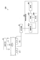
- FIG. 1 is a diagram illustrating a configuration of a structure evaluation system 100 according to the first embodiment.
- the structure evaluation system 100 is used for evaluating the soundness of a structure.
- evaluation means determining the degree of soundness of a structure, that is, determining the deterioration state of the structure based on a certain criterion.
- a bridge made of concrete will be described as an example of a structure, but the structure is not limited to a bridge.
- the structure may be any structure that generates an elastic wave due to the generation or propagation of a crack or an external impact (for example, rain, artificial rain, etc.).
- the bridge is not limited to a structure erected on a river or a valley, but also includes various structures provided above the ground (for example, viaducts of a highway).
- damage that affects the evaluation of the state of deterioration of the structure includes damage inside the structure that hinders propagation of elastic waves such as cracks, cavities, and sedimentation.
- the crack includes a vertical crack, a horizontal crack, an oblique crack, and the like.
- a longitudinal crack is a crack that occurs in a direction perpendicular to the plane of the structure on which the sensor is installed.
- a lateral crack is a crack that occurs in a direction horizontal to the surface of the structure on which the sensor is installed.
- An oblique crack is a crack that occurs in a direction that is not horizontal or vertical to the surface of the structure on which the sensor is installed. Sedimentation is deterioration in which concrete changes into sediment at the boundary between asphalt and concrete slab.
- the structure evaluation system 100 includes an impact applying unit 10, a plurality of sensors 20-1 to 20-n (n is an integer of 2 or more), a signal processing unit 30, and a structure evaluation device 40.
- the signal processing unit 30 and the structure evaluation device 40 are communicably connected by wire or wirelessly.
- the sensors 20-1 to 20-n will be referred to as sensors 20 when not distinguished.
- the impact applying unit 10 generates an elastic wave inside the structure by giving the impact 11 to the structure 50.
- the impact applying unit 10 is, for example, a device provided on a vehicle traveling on the structure 50.
- the impact applying unit 10 applies a large number of impacts 11 to the road surface of the structure 50 with a uniform distribution.
- the impact 11 may be applied to a wide area of the road surface of the structure 50.
- the application of the impact 11 is performed by spraying water droplets, ice particles, solids, continuous hitting with a hammer such as a hammer, heating with a laser, or the like.
- the size and timing of the water droplet colliding with the road surface can be controlled by adjusting the nozzle and controlling the ejection timing. It is desirable that the strength and timing of the impact 11 can be controlled to desired values even in continuous hitting with a hammer or the like.
- the sensor 20 is installed on the structure 50.
- the sensor 20 is installed on a surface opposite to the surface on which the impact applying unit 10 applies the impact 11.
- the sensor 20 has a piezoelectric element, detects an elastic wave generated from inside the structure 50, and converts the detected elastic wave into an AE source signal which is a voltage signal.
- the sensor 20 performs processing such as amplification and frequency limitation on the AE source signal and outputs the processed signal to the signal processing unit 30.
- an acceleration sensor may be used instead of the sensor 20. In this case, the acceleration sensor outputs the signal after the signal processing to the signal processing unit 30 by performing the same processing as the sensor 20.
- the thickness of the structure 50 is, for example, 15 cm or more.
- the signal processing unit 30 receives the AE source signal processed by the sensor 20 as an input.
- the signal processing unit 30 extracts an AE feature amount including information on an elastic wave by performing necessary signal processing such as noise removal and parameter extraction on the input AE source signal.
- the information on the elastic wave is, for example, information such as the amplitude, energy, rise time, duration, frequency, and zero-cross count of the AE source signal.
- the signal processing unit 30 outputs information based on the extracted AE feature amount to the structure evaluation device 40 as an AE signal.
- the AE signal output by the signal processing unit 30 includes information such as a sensor ID, AE detection time, AE source signal amplitude, energy, rise time, and frequency.
- the AE detection time indicates a time at which an elastic wave is detected by the sensor 20.
- the signal processing performed by the signal processing unit 30 includes, for example, noise removal and parameter extraction.
- the information on the elastic wave is, for example, information such as the amplitude, energy, rise time, duration, frequency, and zero-cross count of the AE source signal.
- the signal processing unit 30 outputs information based on the extracted AE feature amount to the structure evaluation device 40 as an AE signal.
- the AE signal output by the signal processing unit 30 includes information such as a sensor ID, AE detection time, AE source signal amplitude, energy, rise time, and frequency.
- the amplitude of the AE source signal is, for example, the value of the maximum amplitude in an elastic wave.
- the energy is, for example, a value obtained by time-integrating the square of the amplitude at each time point. Note that the definition of energy is not limited to the above example, and may be an approximation using, for example, a waveform envelope.
- the rise time is, for example, a time required for the elastic wave to rise from a zero value to a value exceeding a predetermined value.
- the duration is, for example, a time from the start of the rise of the elastic wave until the amplitude becomes smaller than a preset value.
- the frequency is the frequency of the elastic wave.
- the zero-cross count is, for example, the number of times an elastic wave crosses a reference line passing a zero value.
- the structure evaluation device 40 includes a CPU (Central Processing Unit), a memory, and an auxiliary storage device connected by a bus, and executes an evaluation program. By executing the evaluation program, the structure evaluation device 40 functions as a device including the position locating unit 401, the evaluation unit 402, and the display unit 403. Note that all or a part of each function of the structure evaluation device 40 may be realized using hardware such as an ASIC (Application Specific Integrated Circuit), a PLD (Programmable Logic Device), and an FPGA (Field Programmable Gate Array). Good. Further, the evaluation program may be recorded on a computer-readable recording medium.
- ASIC Application Specific Integrated Circuit
- PLD Programmable Logic Device
- FPGA Field Programmable Gate Array
- the computer-readable recording medium is, for example, a portable medium such as a flexible disk, a magneto-optical disk, a ROM, a CD-ROM, or a storage device such as a hard disk built in a computer system. Further, the evaluation program may be transmitted and received via a telecommunication line.
- the position locating unit 401 receives the AE signal output from the signal processing unit 30 as an input. In addition, the position locating unit 401 stores information on the installation position of the sensor 20 installed on the structure 50 (hereinafter, referred to as “sensor position information”) in advance in association with the sensor ID.
- the information on the installation position is, for example, latitude and longitude, or horizontal and vertical distances from a reference position of the structure 50.
- the position locating unit 401 locates the acoustic wave source based on information such as the sensor ID and the AE detection time included in the input AE signal and the sensor position information stored in advance. Specifically, the position locating unit 401 evaluates the position of the elastic wave source based on the arrival time of the elastic wave at the plurality of sensors 20, that is, the difference between the AE detection times. The position locating unit 401 generates an elastic wave source distribution in an evaluation target region in the structure 50 using information on the positions of the plurality of elastic wave sources obtained during a certain period. The evaluation target area in the structure 50 is an area surrounded by the sensor 20. The elastic wave source distribution is a distribution indicating the position of the evaluated elastic wave source. The position locating unit 401 outputs the generated elastic wave source distribution to the evaluation unit 402.
- the evaluation unit 402 receives the elastic wave source distribution output from the position locating unit 401 as an input.
- the evaluation unit 402 evaluates the deterioration state of the structure 50 based on the input elastic wave source distribution and the installation position of the sensor 20. Specifically, the evaluation unit 402 acquires the characteristic amount of the elastic wave in the elastic wave source distribution based on the elastic wave source distribution, and uses the acquired characteristic amount and the installation position of the sensor 20 to deteriorate the structure 50. Evaluate the condition.
- the characteristic amount of the elastic wave in the elastic wave source distribution is, for example, the density of the elastic wave source, the number of elastic waves, and the amplitude of the elastic wave.
- the evaluation unit 402 divides the elastic wave source distribution into regions suitable for evaluation (hereinafter, referred to as “evaluation regions”).
- the evaluation area is set in advance.
- the evaluation area is set so as to be equal to or smaller than the size of the damage to be detected and to include one or more positions where the impact 11 is applied. The smaller the space between the regions, the more the presence or absence of damage can be evaluated.
- the position to which more impact 11 is applied is included in one region, the difference in density becomes more remarkable, and the accuracy of evaluation is further improved.
- the evaluation unit 402 calculates the density of the elastic wave source for each evaluation area. Then, the evaluation unit 402 evaluates the deterioration state of the structure 50 by comparing the density of the elastic wave source calculated for each evaluation area with at least one of a predetermined first threshold and a second threshold. The second threshold is larger than the first threshold. The evaluation unit 402 causes the display unit 403 to display the evaluation result.
- the display unit 403 is an image display device such as a liquid crystal display and an organic EL (Electro Luminescence) display.
- the display unit 403 displays the evaluation result according to the control of the evaluation unit 402.
- the display unit 403 may be an interface for connecting the image display device to the structure evaluation device 40. In this case, the display unit 403 generates a video signal for displaying the evaluation result, and outputs the video signal to an image display device connected thereto.
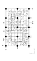
- FIG. 2 is a diagram illustrating an elastic wave source distribution generated by the position locating unit 401 locating the elastic wave source when a uniform impact 11 is applied to the structure 50.
- FIG. 3 is a contour diagram of the elastic wave source distribution in FIG. 2 and 3, the vertical and horizontal axes represent the length (m) of the evaluation target area. 2 and 3 indicate the installation position of the sensor 20. 2 and 3 show a case where 15 sensors 20 are installed. The position of the triangle 55 in FIG. 2 indicates the position of the elastic wave source.
- each of the grid-like regions 56 indicated by dotted lines is an evaluation region.
- the density of the elastic wave source due to the damage is remarkably reduced in the region 60-1, whereas the density of the elastic wave source due to the damage is relatively large in the region 60-2. Therefore, when the evaluation unit 402 evaluates the areas 60-1 and 60-2 using the same one threshold, if the threshold is too low, the density of the elastic wave source of the damaged portion in the area 60-2 does not fall below the threshold. Not rated as damaged. On the other hand, if the threshold value is too large, a slight difference occurs in the density of the elastic wave in the region 60-1 due to a variation in the execution method at the time of measurement such as the condition of applying the impact and the measurement condition. Will be evaluated.
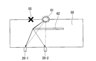
- FIG. 4A is a cross-sectional view of the structure 50 when the sensor 20 is installed immediately below the damage 62.
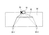
- FIG. 4B is a cross-sectional view of the structure 50 when the sensor 20 is not installed immediately below the damage 62.
- the damage in the lateral direction is shown as an example of the damage 62.
- the damage in the present embodiment is a crack, a cavity, or sedimentation.
- reference numeral 61 indicates a position where the impact 11 is applied.
- the propagation of the elastic wave generated on the upper surface of the structure 50 by the impact 11 given at the application position 61 is hindered by the damage 62, and therefore hardly penetrates the damage 62. Therefore, the elastic wave diffracted by the damage 62 reaches the sensor 20.
- the diffraction angle of the elastic wave is large, the attenuation is large and the elastic wave hardly reaches the sensor 20 immediately below the damage 62. Even if the elastic wave arrives at the sensor 20, the difference between the arrival times at the sensors 20-1 and 20-2 shown in FIG. 4A is equal to the time difference from the end of the damage 62.
- the source 55 is located at the end of the lesion 62. As described above, when the sensor 20 is installed immediately below the damage 62, the density of the acoustic wave source in the region where the damage 62 occurs is significantly reduced.
- the diffraction angle is relatively small, and many of the elastic waves diffract and reach the sensor 20.
- the arrival time difference between the sensors 20-1 and 20-2 shown in FIG. 4B may not be much different from the case where there is no damage 62. Therefore, the number of elastic wave sources located at the position immediately above the damage 62 increases.
- the decrease in the density of the elastic wave source in the area where the damage occurs is smaller than when the sensor 20 is installed just below the damage 62. Small.
- the degree of decrease in the density of the elastic wave source differs depending on whether the sensor 20 is installed below the region where the damage 62 has occurred. Therefore, the structure evaluation device 40 according to the present embodiment evaluates the deterioration state of the structure 50 based on the distribution of the acoustic wave sources and the installation position of the sensor 20.
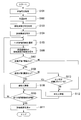
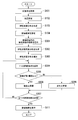
- FIG. 5 is a flowchart illustrating a flow of a deterioration state evaluation process performed by the structure evaluation device 40 according to the first embodiment.
- the position locating unit 401 acquires the AE signal output from the signal processing unit 30 (Step S101).
- the position locating unit 401 locates the acoustic wave source based on the information such as the sensor ID and the AE detection time included in the acquired AE signal and the sensor position information stored in advance (Step S102). Thereafter, the position locating unit 401 generates an elastic wave source distribution using the result of the position locating (Step S103).
- the position locating unit 401 outputs the generated elastic wave source distribution and information on the installation position of the sensor 20 to the evaluation unit 402.
- the evaluation unit 402 acquires the elastic wave source distribution output from the position locating unit 401 and information on the installation position of the sensor 20.
- the evaluation unit 402 sets an evaluation area for the acquired elastic wave source distribution (Step S104). For example, as shown in FIG. 2, the evaluation unit 402 sets an evaluation area (the area 56 shown in FIG. 2) for the elastic wave source distribution.
- the evaluation unit 402 selects one evaluation area from the set evaluation areas (Step S105). At this time, the evaluation unit 402 selects an evaluation area that has not been compared with the threshold. Next, the evaluation unit 402 derives the density of the elastic wave source in the selected evaluation area (Step S106). The evaluation unit 402 determines whether the derived density (first feature amount) of the elastic wave source is equal to or greater than a first threshold (Step S107). If the density of the elastic wave source is equal to or higher than the first threshold (YES in Step S107), the evaluation unit 402 determines whether the derived density (first feature amount) of the elastic wave source is equal to or higher than the second threshold. (Step S108).
- the evaluation unit 402 evaluates the selected evaluation area as sound (step S109). The evaluation unit 402 determines whether all the evaluation areas have been evaluated (step S110). When all the evaluation areas have been evaluated (step S110—YES), the evaluation unit 402 outputs the evaluation result to the display unit 403.
- the display unit 403 displays the evaluation result according to the control of the evaluation unit 402 (Step S111). Specifically, the display unit 403 superimposes and displays the evaluation result (healthy or deteriorated) for each evaluation region of the elastic wave source distribution.
- step S110 when all the evaluation areas have not been evaluated (step S110-NO), the evaluation unit 402 executes the processing of step S105 and thereafter. Further, in the processing of step S107, when the density of the elastic wave source is less than the first threshold (step S107-NO), the evaluation unit 402 evaluates the selected evaluation area as deteriorated (step S112).
- the evaluation unit 402 uses the information on the installation position of the sensor 20 to place the sensor 20 in the selected evaluation area. It is determined whether or not is installed (step S113).
- step S113-YES If the sensor 20 is installed in the selected evaluation area (step S113-YES), the evaluation unit 402 evaluates the selected evaluation area as sound (step S109). On the other hand, when the sensor 20 is not installed in the selected evaluation area (step S113-NO), the evaluation unit 402 evaluates the selected evaluation area as deteriorated (step S112).
- the structure evaluation device 40 evaluates the deterioration state according to the density of the elastic wave source in the evaluation region and the presence or absence of the sensor 20 in the evaluation region. Thereby, the evaluation accuracy of the deterioration state of the structure can be improved. Specifically, when the density of the elastic wave source in the evaluation region is less than the second threshold, the structure evaluation device 40 determines whether the sensor 20 is installed in the evaluation region. In the vicinity where the sensor 20 is installed, the density of the acoustic wave source tends to decrease. Therefore, even if the density of the elastic wave source is less than the second threshold value and the condition for evaluating the deterioration is satisfied, the structure evaluation apparatus 40 sets the evaluation area when the sensor 20 is installed in the evaluation area.
- the structure evaluation device 40 evaluates the evaluation area as deteriorated. With such a configuration, erroneous evaluation due to the installation position of the sensor 20 can be suppressed. Therefore, it is possible to improve the evaluation accuracy of the deterioration state of the structure.
- the structure evaluation device 40 evaluates the deterioration state using two thresholds, such as a first threshold and a second threshold. For example, when the entire structure 50 is damaged, the structure evaluation device 40 determines that the entire evaluation area is deteriorated by comparing the first threshold value with the density in the evaluation area. Thus, the structure evaluation device 40 can determine that the structure has deteriorated before comparing the second threshold value with the density in the evaluation region. Therefore, the evaluation accuracy can be improved more than when the deterioration state of the structure is evaluated using only the second threshold value.
- two thresholds such as a first threshold and a second threshold.
- the structure evaluation device 40 is configured to compare the first threshold value and the second threshold value with the density of the elastic wave source which is one of the characteristic amounts of the elastic wave in the elastic wave source distribution.
- the processing of the object evaluation device 40 does not need to be limited to this.
- the structure evaluation device 40 compares the amplitude of the elastic wave (the second characteristic amount), which is one of the characteristic amounts of the elastic wave in the elastic wave source distribution, with a first threshold value for the amplitude of the elastic wave. It may be configured to compare the two thresholds with the density (first feature value) of the elastic wave source.
- the evaluation unit 402 derives the average value of the amplitude of the elastic wave for each evaluation area, and compares the average value of the derived amplitude with the first threshold.
- the structure evaluation device 40 may be configured to evaluate the deterioration state of the structure 50 based on one threshold and the installation position of the sensor 20. In such a configuration, the structure evaluation device 40 does not execute the processing in step S107, and executes the processing in step S108 after the processing in step S106.
- FIG. 6 is a diagram illustrating a configuration of the structure evaluation system 100a according to the second embodiment.
- the structure evaluation system 100a includes an impact applying unit 10, a plurality of sensors 20-1 to 20-n, a signal processing unit 30, and a structure evaluation device 40a.
- the structure evaluation system 100a differs from the structure evaluation system 100 in that a structure evaluation device 40a is provided instead of the structure evaluation device 40.
- a structure evaluation device 40a is provided instead of the structure evaluation device 40.
- the structure evaluation device 40a includes a CPU, a memory, an auxiliary storage device, and the like connected by a bus, and executes an evaluation program. By executing the evaluation program, the structure evaluation device 40a functions as a device including the position locating unit 401, the evaluation unit 402a, and the display unit 403. Note that all or a part of each function of the structure evaluation device 40a may be realized using hardware such as an ASIC, a PLD, and an FPGA. Further, the evaluation program may be recorded on a computer-readable recording medium.
- the computer-readable recording medium is, for example, a portable medium such as a flexible disk, a magneto-optical disk, a ROM, a CD-ROM, or a storage device such as a hard disk built in a computer system. Further, the evaluation program may be transmitted and received via a telecommunication line.
- the structure evaluation device 40a differs from the structure evaluation device 40 in that an evaluation unit 402a is provided instead of the evaluation unit 402. Other structures of the structure evaluation device 40a are the same as those of the structure evaluation device 40. Therefore, only differences between the evaluation unit 402a and the evaluation unit 402 will be described.
- the evaluation unit 402a evaluates the deterioration state of the structure 50 according to whether the evaluation area is included in a predetermined range centered on each sensor 20.
- the predetermined range around the sensor 20 is a range defined around the sensor 20, and may be, for example, a range of a radius D around the sensor 20 or an X direction around the sensor 20. And a rectangular range having different distances in the Y direction.
- the distance D is set sufficiently smaller than the sensor interval.
- the evaluation unit 402a outputs the evaluation result to the display unit 403.
- FIG. 7 is a flowchart illustrating a flow of a deterioration state evaluation process performed by the structure evaluation device 40a according to the second embodiment.
- the same reference numerals are given to the same processes as those in FIG. 5, and the description will be omitted.
- the evaluation unit 402a determines whether or not the evaluation area is included in a predetermined range around each sensor 20. (Step S201). When a part or all of the evaluation area is included in a predetermined range centered on each sensor 20, the evaluation unit 402a determines that the evaluation area is included in the predetermined range centered on each sensor 20. judge. The evaluation unit 402a determines that the evaluation area is not included in the predetermined range centered on each sensor 20 when all the evaluation areas are not included in the predetermined range centered on each sensor 20.
- the evaluation unit 402a evaluates the selected evaluation area as sound (step S109). On the other hand, when the evaluation area is not included in the predetermined range around the sensors 20 (step S201-NO), the evaluation unit 402a evaluates the selected evaluation area as deteriorated (step S112).
- the structure evaluation system 100a configured as described above determines whether the evaluation region is included in a predetermined range around the sensor 20 when the density of the elastic wave source in the evaluation region is less than the second threshold. judge. As described above, the density of the acoustic wave source tends to be low near the position where the sensor 20 is installed. Therefore, the structure evaluation apparatus 40a is configured such that even if the density of the elastic wave source is less than the second threshold value and the condition for evaluating deterioration is satisfied, the evaluation area is included in a predetermined range around the sensor 20. Evaluates the evaluation area as sound.
- the structure evaluation device 40a evaluates the evaluation area as deteriorated. With such a configuration, erroneous evaluation due to the installation position of the sensor 20 can be suppressed. Therefore, it is possible to improve the evaluation accuracy of the deterioration state of the structure.
- the structure evaluation system 100a according to the second embodiment may be modified similarly to the structure evaluation system 100.
- FIG. 8 is a diagram illustrating a configuration of a structure evaluation system 100b according to the third embodiment.
- the structure evaluation system 100b includes an impact applying unit 10, a plurality of sensors 20-1 to 20-n, a signal processing unit 30, and a structure evaluation device 40b.
- the structure evaluation system 100b differs from the structure evaluation system 100 in that a structure evaluation device 40b is provided instead of the structure evaluation device 40.
- a structure evaluation device 40b is provided instead of the structure evaluation device 40.
- the structure evaluation device 40b includes a CPU, a memory, an auxiliary storage device, and the like connected by a bus, and executes an evaluation program. By executing the evaluation program, the structure evaluation device 40b functions as a device including the position locating unit 401, the evaluation unit 402b, the display unit 403, and the correction unit 404b. Note that all or a part of each function of the structure evaluation device 40b may be realized using hardware such as an ASIC, a PLD, and an FPGA. Further, the evaluation program may be recorded on a computer-readable recording medium.
- the computer-readable recording medium is, for example, a portable medium such as a flexible disk, a magneto-optical disk, a ROM, a CD-ROM, or a storage device such as a hard disk built in a computer system. Further, the evaluation program may be transmitted and received via a telecommunication line.
- the structure evaluation device 40b differs from the structure evaluation device 40 in that an evaluation unit 402b is provided instead of the evaluation unit 402 and a correction unit 404b is newly provided.
- Other structures of the structure evaluation device 40b are the same as those of the structure evaluation device 40. Therefore, only the evaluation unit 402b and the correction unit 404b will be described.
- the evaluation unit 402b generates an elastic wave source density distribution by using the derived elastic wave source density and the elastic wave source distribution for each evaluation area.
- the elastic wave source density distribution is a distribution indicating the density of the elastic wave source.
- the elastic wave source density distribution is represented by a contour diagram as shown in FIG.
- the evaluation unit 402b evaluates the deterioration state of the structure based on the corrected elastic wave source density distribution corrected by the correction unit 404.
- the evaluation unit 402b outputs the evaluation result to the display unit 403.
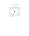
- the correction unit 404 corrects the elastic wave source density distribution by performing different processing on the elastic wave source density distribution according to the distance from the position of the sensor 20. Specific processing of the correction unit 404 will be described with reference to FIG.
- FIG. 9 is a diagram for explaining processing by the correction unit 404.
- the correction unit 404 does not perform correction on the area 70 within the distance D from the installation position of the sensor 20 in the area of the elastic wave source density distribution. Further, the correction unit 404 performs the following correction on the region 71 where the distance from the installation position of the sensor 20 is outside D, that is, the region 71 that is more than the distance D from the installation position of the sensor 20 in the region of the elastic wave source density distribution. .
- the corrected elastic wave source density p ′ is derived.
- M is an average elastic wave source density in a healthy region.
- the correction coefficient k and the distance D do not need to be constants, and a coefficient or the like that continuously changes according to measurement conditions such as a sensor interval may be used.
- FIG. 10 is a flowchart illustrating a flow of a deterioration state evaluation process performed by the structure evaluation device 40b according to the third embodiment.
- the same reference numerals are given to the same processes as those in FIG. 5, and the description will be omitted.
- the evaluation unit 402b derives the density of the acoustic wave source for each evaluation area (step S301).
- the evaluation unit 402b generates an elastic wave source density distribution by using the derived elastic wave source density and the elastic wave source distribution for each evaluation region (Step S302).
- the evaluation unit 402b outputs the generated elastic wave source density distribution to the correction unit 404.
- the correction unit 404b corrects the generated elastic wave source density distribution according to the installation position of the sensor 20, thereby generating a corrected elastic wave source density distribution (step S303).
- the correction unit 404b outputs the corrected elastic wave source density distribution to the evaluation unit 402b.
- the evaluation unit 402b selects one of the evaluation regions in the corrected elastic wave source density distribution output from the correction unit 404b (step S304).
- the evaluation area in the corrected elastic wave source density distribution is the same as the evaluation area set for the elastic wave source distribution by the evaluation unit 402b in the process of step S104.
- the evaluation unit 402b determines whether the density of the elastic wave source in the selected evaluation region is equal to or higher than the first threshold (Step S305). When the density of the elastic wave source is equal to or larger than the first threshold (YES in Step S305), the evaluation unit 402b evaluates the selected evaluation area as sound (Step S306). The evaluation unit 40b2 determines whether or not all the evaluation areas have been evaluated (Step S307). When all the evaluation areas have been evaluated (YES in step S307), the evaluation unit 402b outputs the evaluation result to the display unit 403.
- step S307 when all the evaluation areas have not been evaluated (step S307-NO), the evaluation unit 402b executes the processing of step S304 and thereafter. Further, in the process of step S305, when the density of the elastic wave source is less than the first threshold value (step S305-NO), the evaluation unit 402b evaluates the selected evaluation region as deteriorated (step S308).
- the structure evaluation system 100b configured as described above evaluates the deterioration state of the structure 50 by correcting the elastic wave source density distribution according to the distance from the installation position of the sensor 20. By correcting the elastic wave source density distribution with the correction coefficient, the density indicated by the elastic wave source density distribution is corrected. With such a configuration, erroneous evaluation due to the installation position of the sensor 20 can be suppressed. Therefore, it is possible to improve the evaluation accuracy of the deterioration state of the structure.
- the structure evaluation systems 100, 100a, and 100b may include three or more sensors 20.
- the structure evaluation systems 100, 100a, and 100b may not include the impact applying unit 10.
- the impact 11 on the structure 50 may be given manually.
- the impact 11 on the structure 50 by hand is, for example, spraying of water droplets, ice particles, and solids, continuous hitting with a hammer such as a hammer or a hammer, or heating with a laser.
- the evaluation area does not need to be limited to a lattice shape as shown in FIG. Specifically, the evaluation area may be any area that is equal to or smaller than the size of the damage to be detected and includes one or more positions where the impact 11 is applied.
- the evaluation area may be a circle, a rectangle having a plurality of vertices (for example, an n-gon (n is an integer of 3 or more)), or an area specified by handwriting.
- the evaluation area may be an area smaller than the size of the damage to be detected.
- the structure evaluation device 40 may include only the evaluation unit 402, and the position locating unit 401 and the display unit 403 may be provided in different housings.
- the evaluation unit 402 acquires the elastic wave source distribution from another housing, and evaluates the soundness of the structure using the acquired elastic wave source distribution. Then, the evaluation unit 402 outputs the evaluation result to the display unit 403 provided in another housing.
- the production cost of the structure evaluation device 40 can be reduced by using an existing device for deriving the elastic wave source distribution.
- the signal processing unit 30 may be configured to perform signal processing on an AE source signal having an amplitude value higher than a first threshold value higher than a noise level among input AE source signals. Specifically, first, when a large vibration is detected as compared with the first threshold, the signal processing unit 30 determines that a signal for a predetermined time from the time when the first threshold is exceeded is regarded as an elastic wave waveform. , Save the AE source signal having an amplitude value higher than the first threshold. Then, the signal processing unit 30 extracts an AE feature amount including information on the elastic wave based on the elastic wave waveform data indicated by the stored AE source signal. Note that the first threshold is set in advance.
- the signal processing unit 30 may be provided in the structure evaluation device 40 (or the structure evaluation device 40a, the structure evaluation device 40b). In such a configuration, the signal processing unit 30 acquires the AE source signal processed by the sensor 20 directly from the sensor 20 or via a relay device (not illustrated).
- one signal processing unit 30 is connected to a plurality of sensors 20-1 to 10-n, but a plurality of structure evaluation systems 100 (or a structure evaluation system 100a and a structure evaluation system 100b) are provided. It may be configured to include a plurality of signal processing units 30 and to connect the signal processing units 30 to the respective sensors 20 to include a plurality of sensor units.
- ⁇ Evaluation unit 402 may operate as an output control unit.
- the output control unit controls the output unit and outputs an evaluation result.
- the output unit includes a display unit 403, a communication unit, and a printing unit.
- the output control unit controls the communication unit and transmits an evaluation result to another device.
- the output unit is a printing unit
- the output control unit controls the printing unit and prints the evaluation result.
- the structure evaluation device 40 (or the structure evaluation device 40a, the structure evaluation device 40b) includes a display unit 403, a communication unit, and a part or all of a printing unit as an output unit, and executes the above operation. You may.
- a plurality of sensors for detecting elastic waves and a position locating unit for locating the position of the elastic wave source based on the plurality of elastic waves detected by each of the plurality of sensors,
- an evaluation unit that evaluates the state of deterioration of a structure according to the distribution of an elastic wave source obtained based on the position of an elastic wave source and the presence or absence of a sensor, it is possible to improve the evaluation accuracy of the state of deterioration of a structure. it can.
Landscapes
- Physics & Mathematics (AREA)
- Biochemistry (AREA)
- Health & Medical Sciences (AREA)
- Life Sciences & Earth Sciences (AREA)
- Chemical & Material Sciences (AREA)
- Analytical Chemistry (AREA)
- General Health & Medical Sciences (AREA)
- General Physics & Mathematics (AREA)
- Immunology (AREA)
- Pathology (AREA)
- Acoustics & Sound (AREA)
- Engineering & Computer Science (AREA)
- Signal Processing (AREA)
- Investigating Or Analyzing Materials By The Use Of Ultrasonic Waves (AREA)
Priority Applications (7)
| Application Number | Priority Date | Filing Date | Title |
|---|---|---|---|
| CN201880055335.XA CN111183358B (zh) | 2018-09-13 | 2018-09-13 | 构造物评价系统、构造物评价装置以及构造物评价方法 |
| PCT/JP2018/034004 WO2020054026A1 (ja) | 2018-09-13 | 2018-09-13 | 構造物評価システム、構造物評価装置及び構造物評価方法 |
| EP18933584.7A EP3851849A4 (en) | 2018-09-13 | 2018-09-13 | STRUCTURE EVALUATION SYSTEM, STRUCTURE EVALUATION DEVICE AND STRUCTURE EVALUATION METHOD |
| JP2020508055A JP6857777B2 (ja) | 2018-09-13 | 2018-09-13 | 構造物評価システム、構造物評価装置及び構造物評価方法 |
| US17/184,667 US12332214B2 (en) | 2018-09-13 | 2021-02-25 | Structure soundness evaluation using elastic waves on divided areas |
| JP2021047844A JP7222014B2 (ja) | 2018-09-13 | 2021-03-22 | 構造物評価システム、構造物評価装置及び構造物評価方法 |
| US19/213,232 US20250277772A1 (en) | 2018-09-13 | 2025-05-20 | Structure soundness evaluation using elastic waves on divided areas |
Applications Claiming Priority (1)
| Application Number | Priority Date | Filing Date | Title |
|---|---|---|---|
| PCT/JP2018/034004 WO2020054026A1 (ja) | 2018-09-13 | 2018-09-13 | 構造物評価システム、構造物評価装置及び構造物評価方法 |
Related Child Applications (1)
| Application Number | Title | Priority Date | Filing Date |
|---|---|---|---|
| US17/184,667 Continuation US12332214B2 (en) | 2018-09-13 | 2021-02-25 | Structure soundness evaluation using elastic waves on divided areas |
Publications (1)
| Publication Number | Publication Date |
|---|---|
| WO2020054026A1 true WO2020054026A1 (ja) | 2020-03-19 |
Family
ID=69778245
Family Applications (1)
| Application Number | Title | Priority Date | Filing Date |
|---|---|---|---|
| PCT/JP2018/034004 Ceased WO2020054026A1 (ja) | 2018-09-13 | 2018-09-13 | 構造物評価システム、構造物評価装置及び構造物評価方法 |
Country Status (5)
| Country | Link |
|---|---|
| US (2) | US12332214B2 (enExample) |
| EP (1) | EP3851849A4 (enExample) |
| JP (2) | JP6857777B2 (enExample) |
| CN (1) | CN111183358B (enExample) |
| WO (1) | WO2020054026A1 (enExample) |
Cited By (2)
| Publication number | Priority date | Publication date | Assignee | Title |
|---|---|---|---|---|
| JPWO2022014004A1 (enExample) * | 2020-07-16 | 2022-01-20 | ||
| JP2022165187A (ja) * | 2021-04-19 | 2022-10-31 | 株式会社東芝 | 損傷領域推定システム、推定装置及び損傷領域推定方法 |
Families Citing this family (6)
| Publication number | Priority date | Publication date | Assignee | Title |
|---|---|---|---|---|
| CN115389633B (zh) | 2018-02-27 | 2025-05-30 | 株式会社东芝 | 构造物评价系统以及构造物评价方法 |
| CN111183358B (zh) * | 2018-09-13 | 2023-06-02 | 株式会社东芝 | 构造物评价系统、构造物评价装置以及构造物评价方法 |
| JP7362580B2 (ja) * | 2020-09-16 | 2023-10-17 | 株式会社東芝 | 構造物評価方法、及び構造物評価システム |
| JP7447045B2 (ja) * | 2021-03-22 | 2024-03-11 | 株式会社東芝 | 検査システム、検査装置及び検査方法 |
| JP7508427B2 (ja) * | 2021-09-16 | 2024-07-01 | 株式会社東芝 | 構造物評価システム、構造物評価装置及び構造物評価方法 |
| JP7739245B2 (ja) * | 2022-09-16 | 2025-09-16 | 株式会社東芝 | 構造物評価システム、構造物評価装置、構造物評価方法及びコンピュータプログラム |
Citations (4)
| Publication number | Priority date | Publication date | Assignee | Title |
|---|---|---|---|---|
| US5528557A (en) * | 1995-08-07 | 1996-06-18 | Northrop Grumman Corporation | Acoustic emission source location by reverse ray tracing |
| JP2004125721A (ja) | 2002-10-07 | 2004-04-22 | Railway Technical Res Inst | 2次起因のae音による構造物損傷度判定方法および装置 |
| KR100883446B1 (ko) * | 2008-02-25 | 2009-02-13 | 주식회사 렉터슨 | 음향방출신호를 이용한 결함진단시스템 및 결함진단방법 |
| WO2017217033A1 (ja) * | 2016-06-15 | 2017-12-21 | 株式会社東芝 | 構造物評価システム、構造物評価装置及び構造物評価方法 |
Family Cites Families (27)
| Publication number | Priority date | Publication date | Assignee | Title |
|---|---|---|---|---|
| US5798457A (en) * | 1993-06-25 | 1998-08-25 | Pure Technologies Inc. | Continuous monitoring of reinforcements in structures |
| US7024315B2 (en) * | 2001-02-08 | 2006-04-04 | University Of South Carolina | In-situ structural health monitoring, diagnostics and prognostics system utilizing thin piezoelectric sensors |
| JP4366467B2 (ja) * | 2002-10-28 | 2009-11-18 | 国土交通省国土技術政策総合研究所長 | Aeセンサ及びaeセンサを用いた構造物の異常検出方法並びに安全性評価方法 |
| JP4422988B2 (ja) * | 2003-08-08 | 2010-03-03 | キヤノン株式会社 | 位置検出装置、光学装置、撮像システムおよびプログラム |
| JP4384132B2 (ja) * | 2006-03-08 | 2009-12-16 | 本田技研工業株式会社 | 内燃機関の制御装置 |
| JP4992084B2 (ja) * | 2006-11-29 | 2012-08-08 | 国立大学法人京都工芸繊維大学 | 構造物の損傷の診断システムおよび方法 |
| WO2009001800A1 (ja) * | 2007-06-22 | 2008-12-31 | Nec Corporation | 画質評価装置、画質評価方法およびプログラム |
| CN101221104B (zh) * | 2007-10-16 | 2010-08-11 | 吴智深 | 基于分布式应变动态测试的结构健康监测方法 |
| JP5750066B2 (ja) * | 2012-02-13 | 2015-07-15 | 日立Geニュークリア・エナジー株式会社 | ガイド波を用いた非破壊検査方法 |
| JP6079776B2 (ja) * | 2012-06-06 | 2017-02-15 | 日本電気株式会社 | 構造物の分析装置および構造物の分析方法 |
| JP2014122849A (ja) * | 2012-12-21 | 2014-07-03 | Jfe Steel Corp | 渦流探傷装置および渦流探傷方法 |
| US9470661B2 (en) * | 2013-03-12 | 2016-10-18 | Brigham Young University | Method and system for structural integrity assessment |
| JP6196532B2 (ja) * | 2013-11-05 | 2017-09-13 | 日本電産サンキョー株式会社 | エンコーダ |
| JP6289196B2 (ja) * | 2014-03-20 | 2018-03-07 | 原子燃料工業株式会社 | スイング逆止弁の診断方法 |
| KR101655214B1 (ko) * | 2014-10-02 | 2016-09-07 | 현대자동차 주식회사 | 프레스 판넬의 결함 검출 장치 및 그 방법 |
| JP6567268B2 (ja) * | 2014-11-18 | 2019-08-28 | 株式会社東芝 | 信号処理装置、サーバ装置、検知システム及び信号処理方法 |
| JP2016217974A (ja) * | 2015-05-25 | 2016-12-22 | 三菱電機株式会社 | 測位精度評価装置 |
| JP6674263B2 (ja) * | 2016-01-22 | 2020-04-01 | 東芝テック株式会社 | 変状検出装置 |
| US10539539B2 (en) * | 2016-05-10 | 2020-01-21 | Invensense, Inc. | Operation of an ultrasonic sensor |
| CN113092592B (zh) * | 2016-05-17 | 2024-04-16 | 株式会社东芝 | 构造物评价系统、构造物评价装置以及构造物评价方法 |
| CN106092623B (zh) * | 2016-05-26 | 2019-04-30 | 东南大学 | 一种基于长标距刚度系数的桥梁损伤识别评估方法 |
| US10345275B2 (en) * | 2016-06-15 | 2019-07-09 | Kabushiki Kaisha Toshiba | Structure evaluation system, structure evaluation apparatus, and structure evaluation method |
| US10458954B2 (en) * | 2016-09-15 | 2019-10-29 | Kabushiki Kaisha Toshiba | Structure evaluation system, structure evaluation apparatus, and structure evaluation method |
| US20180149622A1 (en) * | 2016-11-29 | 2018-05-31 | Microline Technology Corporation | Method and apparatus for vibroacoustic modulation crack detection and characterization of conduits and other structures |
| WO2018235195A1 (ja) * | 2017-06-21 | 2018-12-27 | 株式会社東芝 | 構造物評価システム及び構造物評価方法 |
| CN115389633B (zh) * | 2018-02-27 | 2025-05-30 | 株式会社东芝 | 构造物评价系统以及构造物评价方法 |
| CN111183358B (zh) | 2018-09-13 | 2023-06-02 | 株式会社东芝 | 构造物评价系统、构造物评价装置以及构造物评价方法 |
-
2018
- 2018-09-13 CN CN201880055335.XA patent/CN111183358B/zh active Active
- 2018-09-13 WO PCT/JP2018/034004 patent/WO2020054026A1/ja not_active Ceased
- 2018-09-13 JP JP2020508055A patent/JP6857777B2/ja active Active
- 2018-09-13 EP EP18933584.7A patent/EP3851849A4/en active Pending
-
2021
- 2021-02-25 US US17/184,667 patent/US12332214B2/en active Active
- 2021-03-22 JP JP2021047844A patent/JP7222014B2/ja active Active
-
2025
- 2025-05-20 US US19/213,232 patent/US20250277772A1/en active Pending
Patent Citations (4)
| Publication number | Priority date | Publication date | Assignee | Title |
|---|---|---|---|---|
| US5528557A (en) * | 1995-08-07 | 1996-06-18 | Northrop Grumman Corporation | Acoustic emission source location by reverse ray tracing |
| JP2004125721A (ja) | 2002-10-07 | 2004-04-22 | Railway Technical Res Inst | 2次起因のae音による構造物損傷度判定方法および装置 |
| KR100883446B1 (ko) * | 2008-02-25 | 2009-02-13 | 주식회사 렉터슨 | 음향방출신호를 이용한 결함진단시스템 및 결함진단방법 |
| WO2017217033A1 (ja) * | 2016-06-15 | 2017-12-21 | 株式会社東芝 | 構造物評価システム、構造物評価装置及び構造物評価方法 |
Non-Patent Citations (1)
| Title |
|---|
| See also references of EP3851849A4 |
Cited By (5)
| Publication number | Priority date | Publication date | Assignee | Title |
|---|---|---|---|---|
| JPWO2022014004A1 (enExample) * | 2020-07-16 | 2022-01-20 | ||
| JP7323698B2 (ja) | 2020-07-16 | 2023-08-08 | 株式会社東芝 | 構造物評価システム、構造物評価装置及び構造物評価方法 |
| JP2022165187A (ja) * | 2021-04-19 | 2022-10-31 | 株式会社東芝 | 損傷領域推定システム、推定装置及び損傷領域推定方法 |
| US11946906B2 (en) | 2021-04-19 | 2024-04-02 | Kabushiki Kaisha Toshiba | Damaged region determination system, determination apparatus and damaged region determination method |
| JP7532306B2 (ja) | 2021-04-19 | 2024-08-13 | 株式会社東芝 | 損傷領域推定システム、推定装置及び損傷領域推定方法 |
Also Published As
| Publication number | Publication date |
|---|---|
| JPWO2020054026A1 (ja) | 2020-10-22 |
| JP7222014B2 (ja) | 2023-02-14 |
| CN111183358B (zh) | 2023-06-02 |
| US20250277772A1 (en) | 2025-09-04 |
| JP6857777B2 (ja) | 2021-04-14 |
| CN111183358A (zh) | 2020-05-19 |
| US20210181157A1 (en) | 2021-06-17 |
| EP3851849A4 (en) | 2022-05-04 |
| EP3851849A1 (en) | 2021-07-21 |
| US12332214B2 (en) | 2025-06-17 |
| JP2021096266A (ja) | 2021-06-24 |
Similar Documents
| Publication | Publication Date | Title |
|---|---|---|
| JP6857777B2 (ja) | 構造物評価システム、構造物評価装置及び構造物評価方法 | |
| JP6756927B2 (ja) | 構造物評価システム及び構造物評価方法 | |
| JP6917344B2 (ja) | 構造物評価システム、構造物評価装置及び構造物評価方法 | |
| JP6871201B2 (ja) | 構造物評価システム、構造物評価装置及び構造物評価方法 | |
| US10883919B2 (en) | Structure evaluation system and structure evaluation method | |
| US10345275B2 (en) | Structure evaluation system, structure evaluation apparatus, and structure evaluation method |
Legal Events
| Date | Code | Title | Description |
|---|---|---|---|
| ENP | Entry into the national phase |
Ref document number: 2020508055 Country of ref document: JP Kind code of ref document: A |
|
| 121 | Ep: the epo has been informed by wipo that ep was designated in this application |
Ref document number: 18933584 Country of ref document: EP Kind code of ref document: A1 |
|
| NENP | Non-entry into the national phase |
Ref country code: DE |
|
| ENP | Entry into the national phase |
Ref document number: 2018933584 Country of ref document: EP Effective date: 20210413 |