WO2020045280A1 - 基板搬送ロボット - Google Patents
基板搬送ロボット Download PDFInfo
- Publication number
- WO2020045280A1 WO2020045280A1 PCT/JP2019/033034 JP2019033034W WO2020045280A1 WO 2020045280 A1 WO2020045280 A1 WO 2020045280A1 JP 2019033034 W JP2019033034 W JP 2019033034W WO 2020045280 A1 WO2020045280 A1 WO 2020045280A1
- Authority
- WO
- WIPO (PCT)
- Prior art keywords
- carrier
- substrate
- opening
- hand
- robot
- Prior art date
- Legal status (The legal status is an assumption and is not a legal conclusion. Google has not performed a legal analysis and makes no representation as to the accuracy of the status listed.)
- Ceased
Links
Images


Classifications
-
- H—ELECTRICITY
- H10—SEMICONDUCTOR DEVICES; ELECTRIC SOLID-STATE DEVICES NOT OTHERWISE PROVIDED FOR
- H10P—GENERIC PROCESSES OR APPARATUS FOR THE MANUFACTURE OR TREATMENT OF DEVICES COVERED BY CLASS H10
- H10P72/00—Handling or holding of wafers, substrates or devices during manufacture or treatment thereof
- H10P72/30—Handling or holding of wafers, substrates or devices during manufacture or treatment thereof for conveying, e.g. between different workstations
- H10P72/34—Handling or holding of wafers, substrates or devices during manufacture or treatment thereof for conveying, e.g. between different workstations the wafers being stored in a carrier, involving loading and unloading
- H10P72/3402—Mechanical parts of transfer devices
-
- B—PERFORMING OPERATIONS; TRANSPORTING
- B25—HAND TOOLS; PORTABLE POWER-DRIVEN TOOLS; MANIPULATORS
- B25J—MANIPULATORS; CHAMBERS PROVIDED WITH MANIPULATION DEVICES
- B25J9/00—Program-controlled manipulators
- B25J9/16—Program controls
- B25J9/1694—Program controls characterised by use of sensors other than normal servo-feedback from position, speed or acceleration sensors, perception control, multi-sensor controlled systems, sensor fusion
- B25J9/1697—Vision controlled systems
-
- B—PERFORMING OPERATIONS; TRANSPORTING
- B25—HAND TOOLS; PORTABLE POWER-DRIVEN TOOLS; MANIPULATORS
- B25J—MANIPULATORS; CHAMBERS PROVIDED WITH MANIPULATION DEVICES
- B25J11/00—Manipulators not otherwise provided for
- B25J11/0095—Manipulators transporting wafers
-
- B—PERFORMING OPERATIONS; TRANSPORTING
- B65—CONVEYING; PACKING; STORING; HANDLING THIN OR FILAMENTARY MATERIAL
- B65G—TRANSPORT OR STORAGE DEVICES, e.g. CONVEYORS FOR LOADING OR TIPPING, SHOP CONVEYOR SYSTEMS OR PNEUMATIC TUBE CONVEYORS
- B65G47/00—Article or material-handling devices associated with conveyors; Methods employing such devices
- B65G47/74—Feeding, transfer, or discharging devices of particular kinds or types
- B65G47/90—Devices for picking-up and depositing articles or materials
- B65G47/905—Control arrangements
-
- H—ELECTRICITY
- H10—SEMICONDUCTOR DEVICES; ELECTRIC SOLID-STATE DEVICES NOT OTHERWISE PROVIDED FOR
- H10P—GENERIC PROCESSES OR APPARATUS FOR THE MANUFACTURE OR TREATMENT OF DEVICES COVERED BY CLASS H10
- H10P72/00—Handling or holding of wafers, substrates or devices during manufacture or treatment thereof
- H10P72/30—Handling or holding of wafers, substrates or devices during manufacture or treatment thereof for conveying, e.g. between different workstations
- H10P72/34—Handling or holding of wafers, substrates or devices during manufacture or treatment thereof for conveying, e.g. between different workstations the wafers being stored in a carrier, involving loading and unloading
- H10P72/3406—Handling or holding of wafers, substrates or devices during manufacture or treatment thereof for conveying, e.g. between different workstations the wafers being stored in a carrier, involving loading and unloading involving removal of lid, door or cover
-
- H—ELECTRICITY
- H10—SEMICONDUCTOR DEVICES; ELECTRIC SOLID-STATE DEVICES NOT OTHERWISE PROVIDED FOR
- H10P—GENERIC PROCESSES OR APPARATUS FOR THE MANUFACTURE OR TREATMENT OF DEVICES COVERED BY CLASS H10
- H10P72/00—Handling or holding of wafers, substrates or devices during manufacture or treatment thereof
- H10P72/50—Handling or holding of wafers, substrates or devices during manufacture or treatment thereof for positioning, orientation or alignment
- H10P72/53—Handling or holding of wafers, substrates or devices during manufacture or treatment thereof for positioning, orientation or alignment using optical controlling means
-
- H—ELECTRICITY
- H10—SEMICONDUCTOR DEVICES; ELECTRIC SOLID-STATE DEVICES NOT OTHERWISE PROVIDED FOR
- H10P—GENERIC PROCESSES OR APPARATUS FOR THE MANUFACTURE OR TREATMENT OF DEVICES COVERED BY CLASS H10
- H10P72/00—Handling or holding of wafers, substrates or devices during manufacture or treatment thereof
- H10P72/70—Handling or holding of wafers, substrates or devices during manufacture or treatment thereof for supporting or gripping
- H10P72/76—Handling or holding of wafers, substrates or devices during manufacture or treatment thereof for supporting or gripping using mechanical means, e.g. clamps or pinches
- H10P72/7602—Handling or holding of wafers, substrates or devices during manufacture or treatment thereof for supporting or gripping using mechanical means, e.g. clamps or pinches the wafers being placed on a robot blade or gripped by a gripper for conveyance
Definitions
- the present invention relates to a substrate transport robot that transfers a substrate to and from a substrate carrier coupled to a load port.
- load ports for clamping a carrier of a substrate, docking and undocking the carrier, and opening and closing a door of the carrier are known.
- a load port is provided, for example, in an EFEM (Equipment ⁇ Front ⁇ End ⁇ Module) which is an interface between the carrier and the substrate processing apparatus.
- EFEM Equipment ⁇ Front ⁇ End ⁇ Module
- Patent Document 1 discloses an automatic transfer system that automatically transfers a cassette (carrier) to a cassette stage of equipment.
- This automatic transport system includes an automatic transport vehicle equipped with a camera and a hand, image recognition means for detecting the presence or absence of a cassette on the stage by capturing and processing an image of the stage with the camera, cassettes and other obstacles Control means for transferring the cassette to the stage if there is no hand.
- a difference may occur between a predetermined mounting reference position on the stage and an actual mounting position of the carrier. If the carrier is docked with the load port opening in such a state, a difference may occur between a predetermined reference coupling position and an actual coupling position of the carrier.
- the transfer of the substrate to and from the carrier is performed by a substrate transfer robot. The substrate transfer robot needs to recognize the shift of the coupling position of the carrier in order to accurately transfer the substrate to the carrier.
- the present invention has been made in view of the above circumstances, and an object of the present invention is to provide a technique for detecting a displacement of a coupling position of a carrier coupled to a load port by a substrate transport robot.
- the substrate transfer robot includes: Transferring the substrate from the second side, opposite to the first side, through the opening to the carrier of the substrate coupled to the opening of the load port at the first side of the load port via the load port.
- a substrate transfer robot A hand holding the substrate, A robot arm connected to the hand and displacing the hand;
- An imaging device attached to the hand or the robot arm;
- a controller for controlling the operation of the robot arm and the imaging device, The controller acquires a captured image including the carrier coupled to the periphery of the opening and the opening, which is captured from the second side by the imaging device, and performs image processing on the captured image, thereby obtaining the carrier. Is characterized by detecting a deviation of the combined position from a predetermined reference combined position.
- the substrate transfer robot it is possible to detect a displacement of the coupling position of the carrier with respect to the load port based on an image captured by an imaging device mounted on the robot itself. This detection result can be reflected on the operation of transferring the substrate to the carrier of the substrate transfer robot.
- a single substrate transfer robot can similarly detect a shift in the coupling position of a carrier with respect to a plurality of load ports. Further, the displacement of the coupling position of the carrier with respect to the load port can be detected regardless of the standard of the load port and the carrier.
- the displacement of the coupling position of the carrier coupled to the load port can be detected by the substrate transport robot.
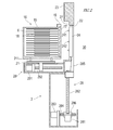
- FIG. 1 is a diagram showing a schematic configuration of a substrate processing facility including a substrate transport robot according to one embodiment of the present invention.
- FIG. 2 is a diagram showing a schematic configuration of the load port shown in FIG.
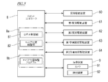
- FIG. 3 is a diagram showing a configuration of a control system of the substrate transfer robot shown in FIG.
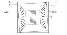
- FIG. 4 is a diagram illustrating Example 1 of the captured image.
- FIG. 5 is a diagram illustrating Example 2 of the captured image.
- FIG. 1 is a diagram illustrating a schematic configuration of a substrate processing facility 100 including a substrate transfer robot 7 according to an embodiment of the present invention
- FIG. 2 is a diagram illustrating a schematic configuration of a load port 2 illustrated in FIG. .
- the substrate processing equipment 100 shown in FIG. 1 includes a load port 2, a substrate transfer device 3, and a substrate processing device 4.
- the substrate transfer device 3 is an interface between the substrate carrier 16 and the substrate processing device 4.
- the carrier 16 includes a box-shaped container 15 for the substrate 6 therein, and a lid 17 for sealing the opening of the container 15.
- a plurality of shelves 18 for mounting the substrate 6 are provided at predetermined intervals in the vertical direction.
- the substrate transfer device 3 includes a housing 31 in which a transfer chamber 30 is formed, and a fan filter unit 5 installed on a ceiling of the housing 31.
- the clean air supplied into the transfer chamber 30 from the fan filter unit 5 flows downward in the transfer chamber 30 and is discharged from the floor of the transfer chamber 30 to the outside of the apparatus.
- the inside of the transfer chamber 30 is maintained at a higher pressure than the external atmosphere, and is maintained at a high clean atmosphere.
- a substrate transfer robot 7 that receives the substrate 6 from the carrier 16 and transfers it to the substrate processing device 4 and receives the substrate 6 from the substrate processing device 4 and transfers it to the carrier 16. Is provided.
- the substrate transfer robot 7 will be described later in detail.
- the substrate processing device 4 is connected to the side surface of the housing 31 of the substrate transfer device 3.
- the substrate processing apparatus 4 may be an apparatus that performs at least one or more of a heat treatment, an impurity introduction process, a thin film formation process, a lithography process, a cleaning process, and a planarization process on the substrate.
- the substrate processing apparatus 4 receives, for example, the load lock chamber 41 for introducing the substrate 6 into the vacuum space, the process chamber 43 for processing the substrate 6, and the substrate 6 between the load lock chamber 41 and the process chamber 43 and loads the same.
- -It has a plurality of vacuum chambers of the transfer chamber 42 for carrying out.
- the substrate transfer device 3 transfers the substrate to the load lock chamber 41.
- the configuration of the substrate processing apparatus 4 is not limited to the above.
- At least one load port 2 is provided on the side surface of the housing 31 of the substrate transfer device 3 opposite to the side surface to which the substrate processing device 4 is connected.
- the load port 2 forms a part of the side surface of the housing 31.
- the load port 2 includes a stage 21 on which the carrier 16 is placed, a plate 23 provided with a port opening 22 serving as a delivery port of the substrate 6, and a port opening 22.
- the vehicle includes a door 24 that opens and closes, a stage driving device 29 that moves the stage 21 forward and backward with respect to the port opening 22, and a door driving device 28 that moves the door 24 up and down.
- the stage 21 is provided with positioning pins 211 for positioning the carrier 16 at a predetermined mounting reference position.
- the carrier 16 is positioned on the stage 21 by fitting the positioning pins 211 into positioning holes provided on the bottom of the carrier 16.
- the positioning hole is a long hole, and a slight displacement of the carrier 16 with respect to the stage 21 may occur.
- the stage 21 is reciprocated by the stage driving device 29.
- the stage driving device 29 includes, for example, a motor 291 and a feed screw 292 driven by the motor 291. As the feed screw 292 rotates forward and backward, the stage 21 moves forward and backward with respect to the port opening 22.
- the carrier 16 moves forward toward the port opening 22 (door 24) as the stage 21 moves forward, the lid 17 of the carrier 16 and the door 24 abut.
- the flange 19 formed on the opening edge of the carrier 16 and the flange panel 27 provided around the port opening 22 come into contact with each other, and the carrier 16 and the plate 23 are connected (docked).
- the door 24 has a registration pin 241 and a latch key 242 for performing integration and positioning on the lid 17 by suction force.
- a latch key hole (not shown) provided in the lid 17 and rotating in the unlocking direction
- the lid 17 is switched to the unlocked state, and the lid 17 and the door 24 are integrated.
- the latch 17 is switched to the locked state by fitting the latch key 242 into a latch key hole (not shown) provided in the lid 17 and rotating in the locking direction, and the lid 17 is integrated with the door 24. It is released.
- the door driving device 28 includes, for example, an elevating motor 281, a feed screw 282 driven by the elevating motor 281, a translation motor 283, and a translation feed screw 284 driven by the translation motor 283.
- the elevating feed screw 282 is screwed into the bracket 285, and the forward / reverse rotation of the elevating feed screw 282 causes the door 24 to move up and down.
- the translation feed screw 284 is screwed into a bracket 286 holding the elevating motor 281, and the forward / reverse rotation of the translation feed screw 284 causes the door 24 to move forward and backward with respect to the port opening 22. .
- the door 17 integrated with the lid 17 retreats from the port opening 22 and then descends, whereby the lid 17 and the door 24 are retracted from the port opening 22 and transferred to the inside of the carrier 16.
- the chamber 30 communicates with the port opening 22.
- FIG. 3 is a diagram showing a configuration of a control system of the substrate transfer robot 7 shown in FIG.
- the substrate transfer robot 7 includes a robot arm (hereinafter, simply referred to as “arm 71”) and a substrate holding hand (hereinafter, simply “hand 72”) connected to a wrist of the arm 71. ), A base 73 supporting the arm 71, the imaging device 9 mounted on the arm 71 or the hand 72, and the robot controller 8.
- the arm 71 is a horizontal articulated robot arm, the arm 71 is not limited to this.
- the arm 71 includes an elevating shaft 70 supported by a base 73 and at least one link 75 or 76.
- the proximal end of the first link 75 is connected to the upper end of the elevating shaft 70 via the first joint J1
- the proximal end of the second link 76 is connected to the distal end of the first link 75. They are connected via a joint J2.
- the proximal end of the hand 72 is connected to the distal end of the second link 76 via a first wrist joint J3 and a second wrist joint J4.
- the first joint J1, the second joint J2, and the first wrist joint J3 are joints that connect the two elements rotatably around a vertical axis.
- the second wrist joint J4 is a joint that connects two elements so as to be rotatable around a horizontal axis.
- the hand 72 includes a hand base 51 connected to the tip of the arm 71 and a blade 52 connected to the hand base 51.
- the blade 52 is provided with a holding device (not shown) for holding the substrate 6. This holding device may be adapted to prevent the substrate 6 placed on the blade 52 from falling off the blade 52 by fitting, adsorbing, holding, or otherwise.
- an elevating drive device 60 that drives the elevating shaft 70 up and down is provided.
- the elevation drive device 60 includes, for example, a servomotor that angularly displaces according to a signal given from the controller 8, a power transmission mechanism that includes a speed reduction device, converts the power of the servomotor into a straight-line force, and transmits it to the elevation shaft 70, And a position detector for detecting the angular displacement of each of them (both are not shown).
- a first joint driving device 61 for driving the first joint J1 and a second joint driving device 62 for driving the second joint J2 are provided in the first link 75.
- a first wrist joint driving device 63 for driving the first wrist joint J3 is provided in the second link 76.
- a second wrist joint driving device 64 for driving the second wrist joint J4 is provided in the hand base 51.
- the drive devices 61 to 64 of the joints J1 to J4 are provided with a servomotor that angularly displaces according to a signal given from the controller 8, a power transmission mechanism including a speed reducer and transmitting the power of the servomotor to the link body, And a position detector for detecting displacement (both not shown).
- the imaging device 9 includes a camera 91 and an irradiation device 92 that irradiates light to an imaging range of the camera 91.
- the imaging device 9 is attached to the hand base 51, but the imaging device 9 may be attached to the arm 71.
- the camera 91 is moved by the arm 71 integrally with the hand 72.
- the controller 8 controls the operation of the substrate transfer robot 7.
- the controller 8 includes a robot control unit 81 and a carrier position adjustment unit 82.
- the controller 8 is a so-called computer and includes, for example, a processor 8a such as a microcontroller, CPU, MPU, PLC, DSP, ASIC, or FPGA, and a memory 8b such as a ROM or a RAM.
- the memory 8b stores a program executed by the processor 8a including a carrier position adjustment program.
- the memory 8b stores data used for processing performed by the processor 8a.
- the processor 8a reads and executes the program stored in the memory 8b, so that processing for functioning as the robot control unit 81 and the carrier position adjusting unit 82 is performed.
- the controller 8 may execute each process by centralized control by a single computer, or may execute each process by distributed control in cooperation with a plurality of computers.
- the robot control unit 81 of the controller 8 controls the operation of the substrate transfer robot 7. More specifically, the robot controller 81 is electrically connected to the elevation drive device 60, the first joint drive device 61, the second joint drive device 62, the first wrist joint drive device 63, and the second wrist joint drive device 64. It is connected to the.
- the robot control unit 81 acquires the rotational positions of the servomotors from the position detectors included in these driving devices, and poses (positions and postures) of the hand 72 corresponding to the rotational positions and the stored teaching point data. Is calculated based on the target pose. Further, the robot control unit 81 outputs a control command to the servo amplifier so that the hand 72 has the target pose.
- the servo amplifier supplies the driving power to each servo motor based on the control command, so that the hand 72 moves to the target pose.
- the carrier position adjusting unit 82 of the controller 8 detects a position shift of the carrier 16 coupled to the load port 2 and reflects the position shift on the operation of the substrate transfer robot 7.
- the carrier position adjustment processing performed by the substrate transfer robot 7 will be described.
- the carrier position adjusting process is performed in a state where the carrier 16 is coupled to the load port 2 and the carrier 16 and the transfer chamber 30 are communicated through the port opening 22. However, the presence or absence of the substrate 6 in the carrier 16 does not matter.
- the controller 8 operates the arm 71 to move the camera 91 so that the periphery of the port opening 22 and the carrier 16 coupled to the port opening 22 enter the imaging range.
- the controller 8 causes the camera 91 to take an image of the periphery of the port opening 22 and the carrier 16 coupled to the port opening 22, and obtains the taken image.
- the camera 91 has a first side (outside the substrate transfer device 3) to which the carrier 16 of the load port 2 is coupled and a second side (inside the substrate transfer device 3) opposite through the load port 2. Then, the port opening portion 22 and the carrier 16 are imaged.
- the controller 8 performs image processing on the acquired captured image to obtain a deviation of the actual coupling position of the carrier 16 from a predetermined reference coupling position defined in the load port 2.
- the reference coupling position refers to the position of the carrier 16 when the carrier 16 is coupled to the port opening 22 without inclination or displacement.
- the controller 8 extracts the profile of the periphery of the port opening 22, the inner wall of the carrier 16 and the profile of the shelf 18 (or the substrate 6) that appear inside the port opening 22 in the captured image. For example, as shown in FIG. 4, the controller 8 can specify the horizontal reference line HD of the port opening 22 in the captured image from the profiles of the upper edge and the lower edge of the port opening 22 in the captured image. Further, the controller 8 can identify the horizontal line H of the carrier 16 in the captured image from the profile of the inner wall of the carrier 16 and the shelf 18 (or the board 6). When the carrier 16 coupled to the load port 2 is at the reference coupling position, the reference horizontal line and the horizontal line are parallel. The controller 8 detects the inclination of the horizontal line of the carrier 16 from the reference horizontal line of the port opening 22 in the captured image, and uses the inclination as a deviation of the coupling position (deviation of the inclination).
- the controller 8 can specify the left edge EDL and the right edge EDR of the port opening 22 in the captured image from the profiles at both ends of the port opening 22 in the horizontal direction.
- the controller 8 can specify the left edge EL and the right edge ER of the carrier 16 in the captured image from the profile of the inner wall of the carrier 16 and the shelf 18 (or the substrate 6).
- the controller 8 determines the distance (left edge opening) of the carrier 16 from the left edge EDL of the port opening 22 in the captured image and the carrier 16 from the right edge EDR of the port opening 22 in the captured image. And the distance of the right edge ER (the opening of the right edge) is determined, and this is determined as the deviation of the joint position (the deviation of the left and right positions).
- the deviation between the left and right positions becomes a predetermined value stored in advance.
- the controller 8 stores an image when the carrier 16 coupled to the load port 2 is at the reference coupling position as a reference image, and compares the reference image with the captured image to determine the reference coupling position. (The deviation of the inclination and the deviation of the left and right positions) of the carrier 16 may be detected.
- the controller 8 detects at least one of the deviation between the inclination and the deviation between the left and right positions, and if the deviation is larger than a threshold value stored in advance, takes into account the deviation to determine the carrier.
- the operation of the arm 71 when transferring the substrate 6 to the substrate 16 is adjusted. More specifically, the carrier position adjustment unit 82 outputs the deviation to the robot control unit 81 as adjustment information, or stores the deviation as adjustment information, and the robot control unit 81 operates the arm 71 in consideration of the adjustment information. Control.
- the target position of the hand 72 is moved vertically or horizontally with respect to the stored (taught) target position, or the main surface of the blade 52 is tilted.
- the hand 72 can access the target substrate 6 more accurately to the shelf plate 18. Therefore, a situation in which the hand 72 and the substrate 6 interfere with each other can be avoided.
- the controller 8 moves the carrier 16 It may be configured to notify the load port 2 to rejoin.
- the substrate transfer robot 7 of the present embodiment uses the load port 2 via the load port 2 with respect to the carrier 16 of the substrate 6 coupled to the opening 22 of the load port 2 on the first side of the load port 2.
- a substrate transfer robot 7 that transfers the substrate 6 from the second side opposite to the first side through the opening 22, and a hand 72 that holds the substrate 6 and a robot that is connected to the hand 72 and displaces the hand 72.
- An arm 71, an imaging device 9 attached to the hand 72 or the robot arm 71, and a controller 8 for controlling the operations of the robot arm 71 and the imaging device 9 are provided.
- the controller 8 acquires a captured image including the periphery of the opening 22 and the carrier 16 coupled to the opening 22 captured from the second side by the imaging device 9 and performs image processing on the captured image. It is characterized in that a deviation of the sixteen coupling positions from a predetermined reference coupling position is detected.
- the displacement of the coupling position of the carrier 16 with respect to the load port 2 can be detected based on the image captured by the imaging device 9 mounted on the robot itself. This detection result can be reflected on the operation of transferring the substrate 6 to the carrier 16 of the substrate transfer robot 7. Further, the displacement of the coupling position of the carrier 16 with respect to the plurality of load ports 2 can be similarly detected by one substrate transfer robot 7. Further, regardless of the standard of the load port 2 and the carrier 16, the displacement of the coupling position of the carrier 16 with respect to the load port 2 can be similarly detected.
- the controller 8 adjusts the operation of the robot arm 71 in consideration of the deviation when the robot arm 71 transfers the substrate to the carrier 16. May have been.
- the hand 72 can more accurately access the target substrate 6. Therefore, the transfer operation of the substrate 6 by the hand 72 is stabilized, and the situation in which the hand 72 interferes with the substrate 6 can be avoided.
- the deviation may include the inclination of the horizontal line of the carrier 16 from the reference horizontal line defined in the opening 22.
- the controller 8 can know whether the carrier 16 coupled to the load port 2 is inclined from the reference coupling position.
- the deviation may include the distance between the horizontal end of the opening 22 and the horizontal end of the carrier 16.
- the controller 8 can know whether or not the carrier 16 coupled to the load port 2 is displaced in the horizontal direction (left-right direction) from the reference coupling position.
Landscapes
- Engineering & Computer Science (AREA)
- Mechanical Engineering (AREA)
- Robotics (AREA)
- Container, Conveyance, Adherence, Positioning, Of Wafer (AREA)
- Manipulator (AREA)
Abstract
Description
ロードポートの第1側において当該ロードポートの開口部と結合された基板のキャリアに対し、前記ロードポートを介して前記第1側と反対の第2側から前記開口部を通じて前記基板の受け渡しを行う基板搬送ロボットであって、
前記基板を保持するハンドと、
前記ハンドと連結され当該ハンドを変位させるロボットアームと、
前記ハンド又は前記ロボットアームに取り付けられた撮像装置と、
前記ロボットアーム及び前記撮像装置の動作を制御するコントローラと、を備え、
前記コントローラは、前記撮像装置で前記第2側から撮像した前記開口部の周縁及び当該開口部に結合された前記キャリアを含む撮像画像を取得し、前記撮像画像を画像処理することにより、前記キャリアの結合位置の所定の基準結合位置からの偏差を検出することを特徴としている。
以下に本発明の実施形態を、図面を参照して詳しく説明する。図1は、本発明の一実施形態に係る基板搬送ロボット7を含む基板処理設備100の概略構成を示す図であり、図2は、図1に示すロードポート2の概略構成を示す図である。図1に示す基板処理設備100は、ロードポート2、基板移載装置3、及び基板処理装置4を備える。
次に、基板搬送ロボット7の構成について詳細に説明する。図3は、図1に示す基板搬送ロボット7の制御系統の構成を示す図である。
3 :基板移載装置
4 :基板処理装置
5 :ファンフィルタユニット
6 :基板
7 :基板搬送ロボット
8 :ロボットコントローラ
8a :プロセッサ
8b :メモリ
9 :撮像装置
15 :容器
16 :キャリア
17 :蓋
18 :棚板
19 :フランジ
21 :ステージ
22 :ポート開口部
23 :プレート
24 :ドア
27 :フランジパネル
28 :ドア駆動装置
29 :ステージ駆動装置
30 :移載室
31 :筐体
41 :ロードロックチャンバ
42 :トランスファチャンバ
43 :プロセスチャンバ
51 :ハンド基部
52 :ブレード
60~65 :駆動装置
70 :昇降軸
71 :ロボットアーム
72 :ハンド
73 :基台
75,76:リンク
81 :ロボット制御部
82 :キャリア位置調整部
91 :カメラ
92 :照射装置
100 :基板処理設備
Claims (4)
- ロードポートの第1側において当該ロードポートの開口部と結合された基板のキャリアに対し、前記ロードポートを介して前記第1側と反対の第2側から前記開口部を通じて前記基板の受け渡しを行う基板搬送ロボットであって、
前記基板を保持するハンドと、
前記ハンドと連結され当該ハンドを変位させるロボットアームと、
前記ハンド又は前記ロボットアームに取り付けられた撮像装置と、
前記ロボットアーム及び前記撮像装置の動作を制御するコントローラと、を備え、
前記コントローラは、前記撮像装置で前記第2側から撮像した前記開口部の周縁及び当該開口部に結合された前記キャリアを含む撮像画像を取得し、前記撮像画像を画像処理することにより、前記キャリアの結合位置の所定の基準結合位置からの偏差を検出する、
基板搬送ロボット。 - 前記コントローラは、前記ロボットアームが前記キャリアに対し前記基板を受け渡す際に前記偏差を加味して前記ロボットアームの動作を調整する、
請求項1に記載の基板搬送ロボット。 - 前記偏差は、前記開口部に規定された基準水平ラインからの前記キャリアの水平ラインの傾きを含む、
請求項1又は2に記載の基板搬送ロボット。 - 前記偏差は、前記開口部の水平方向の端部からの前記キャリアの水平方向の端部の距離を含む、
請求項1~3のいずれか一項に記載の基板搬送ロボット。
Priority Applications (3)
| Application Number | Priority Date | Filing Date | Title |
|---|---|---|---|
| KR1020217009270A KR102436446B1 (ko) | 2018-08-31 | 2019-08-23 | 기판 반송 로봇 |
| JP2020539415A JP7015394B2 (ja) | 2018-08-31 | 2019-08-23 | 基板搬送ロボット |
| CN201980056597.2A CN112673462B (zh) | 2018-08-31 | 2019-08-23 | 基板搬运机器人 |
Applications Claiming Priority (2)
| Application Number | Priority Date | Filing Date | Title |
|---|---|---|---|
| US16/119,485 US10549427B1 (en) | 2018-08-31 | 2018-08-31 | Substrate transfer robot |
| US16/119,485 | 2018-08-31 |
Publications (1)
| Publication Number | Publication Date |
|---|---|
| WO2020045280A1 true WO2020045280A1 (ja) | 2020-03-05 |
Family
ID=69230285
Family Applications (1)
| Application Number | Title | Priority Date | Filing Date |
|---|---|---|---|
| PCT/JP2019/033034 Ceased WO2020045280A1 (ja) | 2018-08-31 | 2019-08-23 | 基板搬送ロボット |
Country Status (6)
| Country | Link |
|---|---|
| US (1) | US10549427B1 (ja) |
| JP (1) | JP7015394B2 (ja) |
| KR (1) | KR102436446B1 (ja) |
| CN (1) | CN112673462B (ja) |
| TW (1) | TWI693134B (ja) |
| WO (1) | WO2020045280A1 (ja) |
Cited By (5)
| Publication number | Priority date | Publication date | Assignee | Title |
|---|---|---|---|---|
| CN111554601A (zh) * | 2020-04-27 | 2020-08-18 | 上海果纳半导体技术有限公司 | 晶圆前端传送系统 |
| WO2022155882A1 (en) * | 2021-01-22 | 2022-07-28 | Abb Schweiz Ag | Assembling apparatus, assembling method and computer readable storage medium |
| WO2022196712A1 (ja) * | 2021-03-19 | 2022-09-22 | 川崎重工業株式会社 | ウエハ搬送ロボット及びウエハ取出方法 |
| JP2022144940A (ja) * | 2021-03-19 | 2022-10-03 | 株式会社ディスコ | 搬送装置 |
| JP2022184175A (ja) * | 2021-05-31 | 2022-12-13 | 東京エレクトロン株式会社 | 情報処理装置、移載位置教示方法及び基板処理装置 |
Families Citing this family (4)
| Publication number | Priority date | Publication date | Assignee | Title |
|---|---|---|---|---|
| JP7364371B2 (ja) * | 2019-06-28 | 2023-10-18 | 川崎重工業株式会社 | 基板搬送ロボット及び基板搬送ロボットの制御方法 |
| KR102545754B1 (ko) * | 2021-05-27 | 2023-06-20 | 세메스 주식회사 | 기판 처리 장치 및 기판 상태 검출 방법 |
| CN114311094B (zh) * | 2021-12-31 | 2023-10-20 | 福建晟哲自动化科技有限公司 | 一种液晶面板的切裂翻片机 |
| US20250046637A1 (en) * | 2023-08-04 | 2025-02-06 | Jun-Fu Technology Inc | Automatic correction device of robotic arm and method thereof |
Citations (4)
| Publication number | Priority date | Publication date | Assignee | Title |
|---|---|---|---|---|
| JP2002224982A (ja) * | 2000-12-01 | 2002-08-13 | Yaskawa Electric Corp | 薄型基板搬送用ロボットおよび薄型基板検出方法 |
| WO2011062138A1 (ja) * | 2009-11-17 | 2011-05-26 | シンフォニアテクノロジー株式会社 | ウエハ検出装置 |
| JP2011134898A (ja) * | 2009-12-24 | 2011-07-07 | Tokyo Electron Ltd | 基板処理装置、基板処理方法及び記憶媒体 |
| JP2018051670A (ja) * | 2016-09-28 | 2018-04-05 | 川崎重工業株式会社 | ロボット、ロボットの制御装置、及び、ロボットの位置教示方法 |
Family Cites Families (14)
| Publication number | Priority date | Publication date | Assignee | Title |
|---|---|---|---|---|
| JPH05343495A (ja) | 1992-06-05 | 1993-12-24 | Tokyo Electron Tohoku Ltd | 被処理物の移載装置 |
| JP2599310Y2 (ja) | 1993-04-08 | 1999-09-06 | 大日本スクリーン製造株式会社 | 基板処理装置の安全装置 |
| JP3684799B2 (ja) | 1997-12-09 | 2005-08-17 | アシスト シンコー株式会社 | 移動体の停止位置ズレ量検出装置 |
| JP3076287B2 (ja) | 1997-10-28 | 2000-08-14 | 山形日本電気株式会社 | 半導体装置の製造装置 |
| JP3098506B2 (ja) | 1998-12-28 | 2000-10-16 | 九州日本電気株式会社 | 自動搬送方法及び自動搬送システム |
| US6452503B1 (en) | 2001-03-15 | 2002-09-17 | Pri Automation, Inc. | Semiconductor wafer imaging system |
| JP2003282675A (ja) * | 2002-03-20 | 2003-10-03 | Tokyo Seimitsu Co Ltd | ウエハマッピング装置 |
| JP2006032529A (ja) * | 2004-07-14 | 2006-02-02 | Shinko Electric Co Ltd | 搬送装置及び方法 |
| JP2009194046A (ja) * | 2008-02-13 | 2009-08-27 | Hitachi High-Tech Control Systems Corp | 基板搬送装置および基板の偏心補正方法 |
| JP4993614B2 (ja) * | 2008-02-29 | 2012-08-08 | 東京エレクトロン株式会社 | 搬送手段のティーチング方法、記憶媒体及び基板処理装置 |
| WO2010137556A1 (ja) * | 2009-05-27 | 2010-12-02 | ローツェ株式会社 | 雰囲気置換装置 |
| JP5512350B2 (ja) | 2010-03-30 | 2014-06-04 | 川崎重工業株式会社 | 基板搬送ロボットの状態監視装置 |
| JP5880265B2 (ja) * | 2012-05-07 | 2016-03-08 | 株式会社ダイフク | 基板収納設備 |
| JP6556148B2 (ja) * | 2014-09-05 | 2019-08-07 | ローツェ株式会社 | ロードポート及びロードポートの雰囲気置換方法 |
-
2018
- 2018-08-31 US US16/119,485 patent/US10549427B1/en active Active
-
2019
- 2019-08-23 JP JP2020539415A patent/JP7015394B2/ja active Active
- 2019-08-23 KR KR1020217009270A patent/KR102436446B1/ko active Active
- 2019-08-23 WO PCT/JP2019/033034 patent/WO2020045280A1/ja not_active Ceased
- 2019-08-23 CN CN201980056597.2A patent/CN112673462B/zh active Active
- 2019-08-29 TW TW108131072A patent/TWI693134B/zh active
Patent Citations (4)
| Publication number | Priority date | Publication date | Assignee | Title |
|---|---|---|---|---|
| JP2002224982A (ja) * | 2000-12-01 | 2002-08-13 | Yaskawa Electric Corp | 薄型基板搬送用ロボットおよび薄型基板検出方法 |
| WO2011062138A1 (ja) * | 2009-11-17 | 2011-05-26 | シンフォニアテクノロジー株式会社 | ウエハ検出装置 |
| JP2011134898A (ja) * | 2009-12-24 | 2011-07-07 | Tokyo Electron Ltd | 基板処理装置、基板処理方法及び記憶媒体 |
| JP2018051670A (ja) * | 2016-09-28 | 2018-04-05 | 川崎重工業株式会社 | ロボット、ロボットの制御装置、及び、ロボットの位置教示方法 |
Cited By (10)
| Publication number | Priority date | Publication date | Assignee | Title |
|---|---|---|---|---|
| CN111554601A (zh) * | 2020-04-27 | 2020-08-18 | 上海果纳半导体技术有限公司 | 晶圆前端传送系统 |
| CN111554601B (zh) * | 2020-04-27 | 2021-12-28 | 上海果纳半导体技术有限公司 | 晶圆前端传送系统 |
| WO2022155882A1 (en) * | 2021-01-22 | 2022-07-28 | Abb Schweiz Ag | Assembling apparatus, assembling method and computer readable storage medium |
| WO2022196712A1 (ja) * | 2021-03-19 | 2022-09-22 | 川崎重工業株式会社 | ウエハ搬送ロボット及びウエハ取出方法 |
| JP2022144940A (ja) * | 2021-03-19 | 2022-10-03 | 株式会社ディスコ | 搬送装置 |
| JP2022144478A (ja) * | 2021-03-19 | 2022-10-03 | 川崎重工業株式会社 | ウエハ搬送ロボット及びウエハ取出方法 |
| JP7779661B2 (ja) | 2021-03-19 | 2025-12-03 | 川崎重工業株式会社 | ウエハ搬送ロボット及びウエハ取出方法 |
| JP2026020288A (ja) * | 2021-03-19 | 2026-02-06 | 川崎重工業株式会社 | ウエハ搬送ロボット及びウエハ取出方法 |
| JP2022184175A (ja) * | 2021-05-31 | 2022-12-13 | 東京エレクトロン株式会社 | 情報処理装置、移載位置教示方法及び基板処理装置 |
| JP7704502B2 (ja) | 2021-05-31 | 2025-07-08 | 東京エレクトロン株式会社 | 情報処理装置、移載位置教示方法及び基板処理装置 |
Also Published As
| Publication number | Publication date |
|---|---|
| JP7015394B2 (ja) | 2022-02-02 |
| US10549427B1 (en) | 2020-02-04 |
| KR20210049899A (ko) | 2021-05-06 |
| TW202014283A (zh) | 2020-04-16 |
| KR102436446B1 (ko) | 2022-08-25 |
| TWI693134B (zh) | 2020-05-11 |
| CN112673462A (zh) | 2021-04-16 |
| CN112673462B (zh) | 2023-12-26 |
| JPWO2020045280A1 (ja) | 2021-08-10 |
Similar Documents
| Publication | Publication Date | Title |
|---|---|---|
| JP7015394B2 (ja) | 基板搬送ロボット | |
| JP7008573B2 (ja) | 搬送方法および搬送装置 | |
| JP5058836B2 (ja) | 処理装置、処理方法、被処理体の認識方法および記憶媒体 | |
| CN107111251B (zh) | 用于在光刻系统中转移基材的加载锁定系统和方法 | |
| KR100772843B1 (ko) | 웨이퍼 얼라인 장치 및 방법 | |
| JP2007329447A (ja) | 基板搬送装置及び縦型熱処理装置 | |
| WO2008029608A1 (fr) | Dispositif de transfert de substrat, dispositif de traitement de substrat, et procédé de transfert de substrat | |
| JP4607910B2 (ja) | 基板搬送装置及び縦型熱処理装置 | |
| JP2013110270A (ja) | 基板処理装置及び基板処理方法並びに基板処理プログラムを記憶したコンピュータ読み取り可能な記憶媒体 | |
| JP2018056256A (ja) | 基板搬送ハンドの診断システム | |
| JP2010153843A (ja) | 密閉容器の蓋閉鎖方法及び密閉容器の蓋開閉システム | |
| CN107591352A (zh) | 加载端口及包括加载端口的基板输送系统 | |
| US20240157563A1 (en) | Substrate conveyance robot and substrate extraction method | |
| JP2021044440A (ja) | 基板処理装置、および、基板処理方法 | |
| TW202447836A (zh) | 處理系統及教示方法 | |
| US20260014706A1 (en) | Substrate-conveying robot system and substrate-conveying robot | |
| JP2025112377A (ja) | 搬送装置及びウェーハ収納容器洗浄装置 | |
| TWI827094B (zh) | 高度調整裝置及製造裝置 | |
| JP5937809B2 (ja) | 基板搬送システム | |
| WO2021117734A1 (ja) | 部品供給装置および部品搬送システム | |
| KR102341754B1 (ko) | 로봇의 진단 방법 | |
| JP3056549B2 (ja) | 部品の搬送装置 | |
| TWI920885B (zh) | 製造系統及其控制方法 | |
| JP2002359273A (ja) | ウェハー搬送容器用オープナー | |
| NL2015784B1 (en) | Load lock system and method for transferring substrates in a lithography system. |
Legal Events
| Date | Code | Title | Description |
|---|---|---|---|
| 121 | Ep: the epo has been informed by wipo that ep was designated in this application |
Ref document number: 19854216 Country of ref document: EP Kind code of ref document: A1 |
|
| ENP | Entry into the national phase |
Ref document number: 2020539415 Country of ref document: JP Kind code of ref document: A |
|
| NENP | Non-entry into the national phase |
Ref country code: DE |
|
| ENP | Entry into the national phase |
Ref document number: 20217009270 Country of ref document: KR Kind code of ref document: A |
|
| 122 | Ep: pct application non-entry in european phase |
Ref document number: 19854216 Country of ref document: EP Kind code of ref document: A1 |