WO2020044536A1 - 鉄道車両用空調ダクト - Google Patents
鉄道車両用空調ダクト Download PDFInfo
- Publication number
- WO2020044536A1 WO2020044536A1 PCT/JP2018/032356 JP2018032356W WO2020044536A1 WO 2020044536 A1 WO2020044536 A1 WO 2020044536A1 JP 2018032356 W JP2018032356 W JP 2018032356W WO 2020044536 A1 WO2020044536 A1 WO 2020044536A1
- Authority
- WO
- WIPO (PCT)
- Prior art keywords
- air
- duct
- vehicle
- longitudinal direction
- conditioning duct
- Prior art date
Links
Images


Classifications
-
- B—PERFORMING OPERATIONS; TRANSPORTING
- B61—RAILWAYS
- B61D—BODY DETAILS OR KINDS OF RAILWAY VEHICLES
- B61D27/00—Heating, cooling, ventilating, or air-conditioning
- B61D27/0018—Air-conditioning means, i.e. combining at least two of the following ways of treating or supplying air, namely heating, cooling or ventilating
-
- B—PERFORMING OPERATIONS; TRANSPORTING
- B60—VEHICLES IN GENERAL
- B60H—ARRANGEMENTS OF HEATING, COOLING, VENTILATING OR OTHER AIR-TREATING DEVICES SPECIALLY ADAPTED FOR PASSENGER OR GOODS SPACES OF VEHICLES
- B60H1/00—Heating, cooling or ventilating [HVAC] devices
- B60H1/00357—Air-conditioning arrangements specially adapted for particular vehicles
- B60H1/00371—Air-conditioning arrangements specially adapted for particular vehicles for vehicles carrying large numbers of passengers, e.g. buses
-
- Y—GENERAL TAGGING OF NEW TECHNOLOGICAL DEVELOPMENTS; GENERAL TAGGING OF CROSS-SECTIONAL TECHNOLOGIES SPANNING OVER SEVERAL SECTIONS OF THE IPC; TECHNICAL SUBJECTS COVERED BY FORMER USPC CROSS-REFERENCE ART COLLECTIONS [XRACs] AND DIGESTS
- Y02—TECHNOLOGIES OR APPLICATIONS FOR MITIGATION OR ADAPTATION AGAINST CLIMATE CHANGE
- Y02T—CLIMATE CHANGE MITIGATION TECHNOLOGIES RELATED TO TRANSPORTATION
- Y02T30/00—Transportation of goods or passengers via railways, e.g. energy recovery or reducing air resistance
Definitions
- the present invention relates to an air conditioning duct for a railway vehicle that guides air sent from an air conditioner mounted on a railway vehicle in a longitudinal direction of the vehicle and blows the air into a passenger compartment.
- Patent Literature 1 proposes an air conditioning duct having a chamberless structure in which a partition wall between a main duct and a sub duct is removed to form a single ventilation passage (see FIG. 1 of Patent Literature 1). .
- the shape of the partition wall between the main duct and the sub-duct is not required to be corrected by making the chamber-less, but the wind speed of the air blown from the air-conditioning duct in the longitudinal direction of the vehicle is reduced.
- An additional member for uniformity is required. Such an additional member leads to an increase in the weight and cost of the entire air-conditioning duct. Therefore, an air-conditioning duct capable of making the air flow distribution from the air-conditioning duct in the longitudinal direction of the vehicle uniform with a simpler configuration is desired.
- the object of the present invention is to provide an air conditioning duct for a railway vehicle which has a simpler configuration and can make the flow rate distribution of the air blown out from the air conditioning duct in the longitudinal direction of the vehicle uniform.
- an air conditioning duct for a railway vehicle is an air conditioning duct for a railway vehicle that guides air sent from an air conditioner mounted on a railway vehicle, A duct wall forming an air passage for guiding air sent from the device in the longitudinal direction of the vehicle, and a plurality of openings in the duct wall, the air in the air passage being blown out from the air passage toward the passenger cabin, and a plurality of lines arranged in the vehicle longitudinal direction.
- the ratio of the opening area of one of the outlets to the sum of the opening areas of all the outlets opened to the duct wall is in the range of 0.05% or more and 0.65% or less. It is in.
- the ratio of the opening area of one outlet to the total of the opening areas of the outlets is in the range of 0.05% or more and 0.65% or less.
- the pressure difference in the passage can be reduced. Therefore, with a simple configuration, it is possible to make the flow rate distribution of the air blown out from the air conditioning duct in the longitudinal direction of the vehicle uniform.
- An air conditioning duct for a railway vehicle is an air conditioning duct for a railway vehicle that guides air sent from an air conditioner mounted on the railway vehicle, and the air sent from the air conditioning device.
- a duct wall forming a ventilation path that guides the vehicle in the longitudinal direction of the vehicle, and a plurality of outlets that are opened in a lower wall portion of the duct wall and that blow air in the ventilation path from the ventilation path to the passenger compartment side,
- the inner surface of the lower wall portion is divided into a plurality of partial regions in the longitudinal direction of the vehicle such that each of the inner surfaces of the lower wall portion includes the outlet in a plan view, one of the outlets corresponds to an area of one of the partial regions.
- the ratio of the opening area is in the range of 2.0% or more and 7.5% or less.
- the ratio of the opening area of the outlet to the area of the partial region on the inner surface of the lower wall portion is in the range of 2.0% or more and 7.5% or less, in the vehicle longitudinal direction.
- the difference in pressure in the ventilation passage can be reduced. Therefore, with a simple configuration, it is possible to make the flow rate distribution of the air blown out from the air conditioning duct in the longitudinal direction of the vehicle uniform.
- FIG. 2 is a schematic front cross-sectional view of the air conditioning duct cut along the line II-II in FIG. 1.
- FIG. 3 is a schematic front sectional view of the air-conditioning duct cut along the line III-III in FIG. 1.
- FIG. 4 is a schematic front cross-sectional view of the air conditioning duct cut along the line IV-IV in FIG. 1.
- FIG. 5 is a schematic enlarged cross-sectional view of the air-conditioning duct seen from the top along the line VV in FIG.
- FIG. 2 is a schematic enlarged perspective view in which the vicinity of an outlet in the air conditioning duct shown in FIG. 1 is enlarged.
- 13 is a graph showing the relationship between the position of the outlet of the air conditioning duct and the flow rate of the outlet according to the third embodiment.
- 14 is a graph showing the relationship between the position of the outlet of the air conditioning duct and the flow rate of the outlet according to the fourth embodiment.
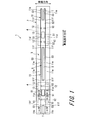
- FIG. 1 is a schematic top view sectional view of a railway vehicle 1 equipped with an air conditioning duct 10 according to the first embodiment.
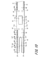
- FIG. 2 is a schematic front sectional view of the air-conditioning duct 10 cut along the line II-II in FIG.
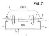
- FIG. 3 is a schematic front sectional view of the air-conditioning duct 10 cut along the line III-III in FIG.
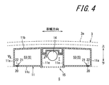
- FIG. 4 is a schematic front cross-sectional view of the air conditioning duct 10 cut along the line IV-IV in FIG.
- the vehicle body 2 of the railway vehicle 1 has a roof structure 3 on its upper part.
- two air conditioners 4 are provided above the roof plate 3a (see FIGS. 2 to 4) of the roof structure 3 at intervals in the vehicle longitudinal direction.
- the air conditioner 4 adjusts the temperature of the air that is a mixture of the air taken in from the passenger compartment 5 and the outside air taken in from outside the vehicle.
- An air conditioning duct 10 extending in the longitudinal direction of the vehicle is disposed above the cabin 5 and inside the roof structure 3. Air whose temperature has been adjusted by the two air conditioners 4 is sent into the air conditioning duct 10. That is, the air conditioning system provided in the railway vehicle 1 of the present embodiment is an integrated and distributed air conditioning system using two large-sized air conditioners per vehicle.
- the air conditioning duct 10 guides the air sent from the two air conditioners 4 in the longitudinal direction of the vehicle, and blows the air into the passenger compartment 5 through a plurality of outlets 20 described later.
- the air conditioning duct 10 includes a duct wall 11 that forms a ventilation path S that guides the air sent from the air conditioner 4 in the longitudinal direction of the vehicle.
- the duct wall 11 is constituted by a plurality of plate-like walls extending in the vehicle longitudinal direction.
- the duct wall 11 of the air conditioning duct 10 is substantially symmetrical in the longitudinal direction of the vehicle and has a structure substantially symmetrical in the width direction of the vehicle.
- the duct wall 11 includes a pair of side walls 11a extending in the vehicle longitudinal direction, an upper wall 11b connecting the upper ends of the pair of side walls 11a in the vehicle width direction, and a lower end of the pair of side walls 11a. It has a lower wall portion 11c connecting the portions in the vehicle width direction.
- FIGS. 1 and 3 eight air outlets 12, four for each air conditioner 4, are opened in the upper wall portion 11 b of the duct wall 11.
- One set of eight air outlets 12 is arranged at intervals in the vehicle width direction, and four sets of air outlets 12 are arranged at intervals in the longitudinal direction of the vehicle. Air is sent from one air conditioner 4 to the ventilation path S through four air outlets 12.
- Ventilation passages S are formed on the center side of the air conditioning duct 10 in the vehicle width direction.
- an air conditioning duct 10 penetrates below the air conditioner 4 between two pairs of air outlets 12 provided corresponding to the air conditioner 4 in the longitudinal direction of the vehicle.
- a return duct 13 extending in the vertical direction is provided.
- the return duct 13 is surrounded on all sides by a side wall 11d which is a part of the duct wall 11 and is located on the center side in the vehicle width direction from the pair of side walls 11a.
- the air conditioner 4 sucks the air in the passenger compartment 5 below the air conditioning duct 10 through the return duct 13.
- An air conditioning plate 16 is provided at an opening from the return duct 13 to the cabin 5.
- a space T for disposing the cross flow fan 14 is provided on the side opposite to the return duct 13 with respect to the air outlet 12.
- the space T is partitioned from the ventilation path S by a pair of side walls 11 e that are part of the duct wall 11 and oppose each other in the vehicle width direction.
- the pair of side wall portions 11e extend parallel to the vehicle longitudinal direction on the center side in the vehicle width direction from the pair of side wall portions 11a.
- a pair of side wall portions 11 f are respectively connected to end portions of the pair of side wall portions 11 e on a side closer to the air outlet 12.
- the pair of side wall portions 11f approach the center in the vehicle width direction as approaching the air outlet 12, and the pair of side wall portions 11f are connected at the center in the vehicle width direction.
- the air conditioner 15 is provided below the cross flow fan 14 in the space T.
- the ventilation path S has a plurality of regions S1, S2, S3 (sections) having different cross sections.
- the first ventilation area S1, the second ventilation area S2, and the third ventilation area S3) are arranged in the vehicle longitudinal direction.
- the first ventilation areas S1 are formed on both sides of the return duct 13 in the vehicle width direction. As shown in FIG. 2, each first ventilation area S1 is sandwiched in the vehicle width direction by the side wall portions 11a and 11d. That is, the first ventilation area S1 is a substantially rectangular area in cross section surrounded by the upper wall 11b, the side wall 11a, the lower wall 11c, and the side wall 11d when viewed from the vehicle longitudinal direction.
- the second ventilation area S2 is continuous with the first ventilation areas S1 on both sides of the return duct 13 in the vehicle width direction in the vehicle longitudinal direction. That is, the second ventilation area S2 is a substantially rectangular area in cross section surrounded by the upper wall portion 11b, the pair of side wall portions 11a, and the lower wall portion 11c when viewed from the vehicle longitudinal direction. As shown in FIG. 3, the air outlet 12 is open in the upper wall portion 11b facing the second ventilation area S2.
- the pair of third ventilation areas S3 is continuous with the second ventilation area S2 on the side opposite to the return duct 13 in the vehicle longitudinal direction.
- the pair of third ventilation areas S3 are respectively located on both sides in the vehicle width direction of the space T in which the cross flow fan 14 is arranged.
- the pair of third ventilation areas S3 extend in the vehicle longitudinal direction with an interval at the center in the vehicle width direction.
- Each third ventilation area S3 is sandwiched in the vehicle width direction by the above-described side wall portions 11a and 11e. That is, the third ventilation area S3 is a substantially rectangular area in cross section surrounded by the upper wall 11b, the side wall 11a, the lower wall 11c, and the side wall 11e when viewed from the vehicle longitudinal direction.
- the air-conditioning duct 10 of the present embodiment employs a chamberless structure in which the ventilation path S faces both the air outlet 12 and the outlet 20. That is, the duct wall 11 is not provided with a partition extending in the vehicle longitudinal direction, which partitions the ventilation path S into a space facing the air outlet 12 and a space facing the outlet 20. The air in the ventilation path S is blown out from the ventilation path S to the passenger room 5 through the plurality of outlets 20.
- a groove 21 extending in the vehicle longitudinal direction is formed on the inner surface (upper surface) of the lower wall portion 11c.
- the groove 21 extends in the vehicle longitudinal direction at a position closer to the outside in the vehicle width direction on the inner surface of the lower wall portion 11c.
- the groove 21 is a portion of the lower wall portion 11c facing the third ventilation region S3 and a part of the second ventilation region S2 (more specifically, in the vehicle longitudinal direction in the second ventilation region S2). (The area between the air outlet 12 and the third ventilation area S3) in the area (see FIG. 10).
- FIG. 5 is a schematic enlarged cross-sectional top view of the air-conditioning duct 10 shown by cutting along the line VV in FIG.
- FIG. 6 is a schematic enlarged perspective view in which the vicinity of the outlet 20 in the air conditioning duct 10 shown in FIG. 1 is enlarged. In FIG. 6, only the bottom 21b of the groove 21 of the lower wall 11c is shown, and the rest is omitted.
- the groove 21 includes a pair of side parts 21a facing each other in the vehicle width direction, and a bottom part 21b connecting lower ends of the pair of side parts 21a.
- a plurality of outlets 20 are provided at the bottom 21b of the groove 21 so as to be arranged at intervals in the longitudinal direction of the vehicle.
- the plurality of outlets 20 have the same size as each other.
- the plurality of outlets 20 have the same shape and the same opening area A.
- each outlet 20 has a length of one side in a vehicle longitudinal direction as d1 and a length of one side in a vehicle width direction as w1. It has a rectangular shape in plan view.
- the plurality of outlets 20 are arranged at a constant pitch p in the vehicle longitudinal direction. That is, the distance (interval) d2 between any two outlets 20 adjacent to each other in the vehicle longitudinal direction is constant.
- the opening area A of each outlet 20 is designed to be smaller than the outlet of a conventional air conditioning duct. Specifically, the ratio X1 of the opening area A of one outlet to the total Aall of the opening areas of all the outlets 20 opened in the duct wall 11 is 0.05% or more and less than 0.15%.
- Each outlet 20 is provided such that
- the ratio X1 can be expressed by the following equation (1), and the air conditioning duct 10 of the present embodiment is designed such that X1 satisfies the following equation (2).
- X1 A / A all ⁇ 100 (1) 0.05 ⁇ X1 ⁇ 0.15 (2)
- the inner surface of the lower wall portion 11c facing the third ventilation area S3 has a plurality of partial areas in the longitudinal direction of the vehicle such that each of the inner surfaces includes one outlet 20 in plan view.
- the ratio X2 of the opening area A of one outlet 20 to the area B of one partial region R when divided into R is within a range of 2.0% or more and less than 5.0%.
- Each outlet 20 is provided. That is, the partial region R is rectangular in a plan view, and one side of the rectangular partial region R extending in the vehicle longitudinal direction is one end of the one outlet 20 in the vehicle longitudinal direction and one end of the adjacent outlet 20 in the vehicle longitudinal direction.
- the other side extending in the vehicle width direction of the partial region R extends from the lower end of the side wall 11a to the lower end of the side wall 11e.
- the ratio X2 can be expressed by the following equation (3).
- X2 is expressed by the following equation (4). Designed to meet.
- each outlet 20 is designed so that the length w1 in the vehicle width direction is longer than the length d1 in the vehicle longitudinal direction.
- the ratio Y can be expressed by the following equation (5).
- a wind receiving plate 22 that receives the air flowing through the ventilation path S is provided to protrude upward on the distal side of the air conditioner 4 at the opening edge of each outlet 20.
- the plurality of air outlets 20 disposed between the two air conditioners 4 are provided with a wind receiving plate 22 on one side in the vehicle longitudinal direction at the opening edge, with the center of the two air conditioners 4 in the vehicle longitudinal direction as a boundary. Are provided, and those provided with the wind receiving plate 22 on the other side in the vehicle longitudinal direction at the opening edge.
- the wind receiving plate 22 is a plate-like body having a substantially rectangular shape when viewed from the vehicle longitudinal direction.
- the wind receiving plates 22 provided at the opening edges of any of the outlets 20 have the same length in the vertical direction.
- the vertical length of the wind receiving plate 22 is designed to be shorter than the vertical length of the side portion 21 a of the groove 21.
- the air-conditioning duct 10 has the above-described ratios X1 and X2 such that the opening area A of each of the plurality of outlets 20 is smaller than the opening area A of the conventional air-conditioning duct.
- Each of the outlets 20 is designed to be continuous at a fine pitch so as to satisfy Expressions (2) and (4).
- Expressions (2) and (4) As a result, the air flowing through the ventilation path S in the longitudinal direction of the vehicle is less likely to flow out of the outlet 20, reducing the velocity of the air flow and reducing the pressure difference in the third ventilation area S3 in the longitudinal direction of the vehicle. Can be. Therefore, with a simple configuration, it is possible to achieve a uniform flow rate distribution of the air blown out from the air conditioning duct 10 in the longitudinal direction of the vehicle.
- each outlet 20 is designed such that the ratio Y satisfies the expression (6) so that the length w1 in the vehicle width direction is longer than the length d1 in the vehicle longitudinal direction. Have been. This makes it difficult for the air flowing through the ventilation path S in the longitudinal direction of the vehicle to escape from the outlet 20, and also in the direction inclined in the vehicle width direction from the outlet 20 to blow out from the air conditioning duct 10 in the longitudinal direction of the vehicle.
- the air flow distribution can be made more uniform.
- a wind receiving plate 22 that receives the air flowing through the ventilation path S protrudes from the opening edge of the outlet 20 on the distal side with respect to the air conditioner 4. Therefore, the wind receiving plate 22 receives the air flowing through the ventilation path S and guides the air to the outlet 20. Thereby, the flow velocity of the air blown out of the air conditioning duct 10 can be reduced, and the air can be blown out from the blowout port 20 to the passenger compartment 5 in a direction more inclined with respect to the longitudinal direction of the vehicle.
- the outer surface of the lower wall portion 11c of the duct wall 11 faces the passenger room 5, and the plurality of outlets 20 are formed at the bottom of the groove 21 formed on the inner surface of the lower wall portion 11c. 21b. Therefore, while ensuring the thickness of the lower wall portion 11c of the duct wall 11 between the cabin 5 and the ventilation path S, the groove 21 is formed at the position where the outlet 20 is arranged on the inner surface of the lower wall portion 11c of the duct wall 11.
- the cross-sectional area of the ventilation path S can be made as large as possible. Thereby, it is possible to reduce the pressure difference in the ventilation path S in the vehicle longitudinal direction while suppressing heat from entering the ventilation path S from the passenger cabin 5 through the duct wall 11.
- the manufacture of the air conditioning duct 10 is easy.
- the air-conditioning duct 10 of the present embodiment employs a chamberless structure.
- no partition is provided in the duct wall 11 and extends in the vehicle longitudinal direction and partitions the ventilation path S into a space facing the air outlet 12 and a space facing the outlet 20.
- the ventilation passage S is divided into a conventional plenum chamber type air conditioning duct, that is, a space in which air is sent through an air outlet and a space in which air is blown out through an air outlet by a partition wall in the duct wall. The production can be facilitated as compared with the duct.
- FIG. 7 is a schematic enlarged perspective view in which the vicinity of the outlet 30 of the air conditioning duct according to the second embodiment is enlarged. Since the configuration of the present embodiment is the same as that of the first embodiment except for the outlet 30, the same reference numerals as those of the first embodiment are given except for the reference numeral of the outlet 30.
- This embodiment is also similar to the first embodiment in that the opening area A of each outlet 30 is designed to be smaller than the outlet of a conventional air conditioning duct. However, the opening area A of the outlet 30 is larger than that of the outlet 20 of the configuration of the first embodiment. That is, in the present embodiment, the ratios X1, X2, and Y are designed to be different from those of the first embodiment.
- the ratios X1 and X2 are designed to satisfy the following equations (7) and (8), respectively. 0.15 ⁇ X1 ⁇ 0.30 (7) 5.0 ⁇ X2 ⁇ 6.5 (8)
- the ratio Y is designed to satisfy the following equation (9). 0.8 ⁇ Y ⁇ 1.2 (9)
- the flow distribution of the air blown out from the air conditioning duct 10 in the longitudinal direction of the vehicle can be made uniform.
- FIG. 8 is a schematic enlarged perspective view in which the vicinity of the outlet 40 of the air conditioning duct according to the third embodiment is enlarged. Since the configuration of the present embodiment is the same as the first and second embodiments except for the outlet 40, the same reference numerals as those in the first and second embodiments are given except for the reference numeral of the outlet 40.
- This embodiment is also similar to the first and second embodiments in that the opening area A of each outlet 40 is designed to be smaller than the outlet of a conventional air conditioning duct. However, the opening area A of the outlet 40 is larger than the opening areas A and 30 of the configurations of the first and second embodiments. That is, in the present embodiment, the ratios X1, X2, and Y are designed to be different from those of the first and second embodiments.
- the ratios X1 and X2 are designed to satisfy the following Expressions (10) and (11), respectively. 0.30 ⁇ X1 ⁇ 0.65 (10) 6.5 ⁇ X2 ⁇ 7.5 (11)
- the ratio Y is designed to satisfy the following expression (12). 1.2 ⁇ Y ⁇ 2.5 (12)
- the flow rate distribution of the air blown out from the air conditioning duct 10 in the vehicle longitudinal direction can be made uniform.
- FIG. 9 is a schematic enlarged perspective view in which the vicinity of the outlet 50 of the air conditioning duct according to the fourth embodiment is enlarged.
- the present embodiment is different from the first embodiment in that the wind receiving plate 22 is not provided at the opening edge of each outlet 50, and the other configuration is the same as that of the first embodiment. That is, in the present embodiment, the ratios X1, X2, and Y are designed to be the same as in the first embodiment.
- the flow distribution of the air blown out from the air conditioning duct 10 in the longitudinal direction of the vehicle can be made uniform.
- the length d1 of the outlet in the vehicle longitudinal direction was 8.6 mm, 24.8 mm, and 57.
- the other dimensions were common to Examples 1 to 3.
- the interval d2 between the two outlets in the vehicle longitudinal direction is 7.6 mm
- the length w1 of the outlet in the vehicle width direction is 29 mm
- the width of the third ventilation area S3 is The dimension w2 in the vehicle width direction was 361 mm.
- the air conditioning duct is mounted on a railway vehicle having a length of 20 m in the longitudinal direction of the vehicle, and the length of the air conditioning duct is equal to the length of the vehicle in which the outlets are arranged at a uniform pitch.
- the length in the direction (hereinafter, referred to as “effective length”) was set to 14 m.
- Table 1 also shows the ratios X1, X2, and Y when the dimensions of the air conditioning duct are set as described above.
- the analysis model of the fourth embodiment has a configuration in which a wind receiving plate is not provided at the opening edge of the outlet, and the dimensions d1, d2, w1, and w2 of the air conditioning duct are common to those of the first embodiment.
- FIG. 10 is a diagram for explaining measurement points of the blowout flow rate analyzed by the numerical analysis.
- 56 measurement points (# 1 to # 56) are arranged in the vehicle longitudinal direction from one end to the other end of the air-conditioning duct in the vehicle longitudinal direction. ) was calculated.
- FIGS. 11 to 14 are graphs showing the relationship between the position of the outlet of the air-conditioning duct and the flow rate of the outlet according to the first to fourth embodiments.
- uniformity in a practically usable range was obtained. Comparing the flow distributions of the first to third embodiments, the uniformity of the flow distribution of the flow distribution of the second embodiment is better than that of the third embodiment, and the uniformity of the flow distribution of the flow distribution of the first embodiment is better than that of the second embodiment. It was good. That is, as the opening area of one outlet is smaller, the uniformity of the flow rate distribution is improved. Further, when comparing the flow rate distributions of Examples 1 and 4, the flow rate distribution of Example 1 was more uniform than that of Example 4.
- the role of the wind baffle is to blow air into the passenger compartment from the outlet in a direction that is more inclined to the longitudinal direction of the vehicle. From this analysis result, the wind baffle contributes to improving the uniformity of the flow distribution. It was also confirmed.
- the ratio X1 is in the range of 0.05% or more and 0.65% or less, the ratio X2 is 2.0% or more, and although it was within the range of 7.5% or less, the air conditioning duct of the present invention is not limited to this. That is, the air-conditioning duct of the present invention has a condition that the ratio X1 is in a range of 0.05% or more and 0.65% or less, and a condition in which the ratio X2 is 2.0% or more and 7.5% or less. It may be a configuration that satisfies only one of the conditions of being within.
- the ratio Y is in the range of 0.25 or more and 2.5 or less, but the present invention is not limited to this. It may be a value larger than 0.5.
- the shape of the outlet is rectangular in a plan view, but is not limited thereto, and may be, for example, a circle (including an ellipse) in a plan view.
- the pitch of the plurality of outlets may not be constant, and may have different opening areas.
- the grooves are formed on the inner surface of the lower wall of the duct wall, but the present invention is not limited to this. That is, the inner surface (upper surface) of the lower wall portion may be a flat surface having a constant height in the vehicle width direction, and the outlet may be opened in this flat surface.
- the ventilation passage has the first to third ventilation regions, but the present invention is not limited to this.
- the air conditioning duct of the present invention may be configured by a right duct portion and a left duct portion which are not connected to each other and are arranged so as to sandwich the cross flow fan 14 in the vehicle width direction.
- the air outlet through which air is sent from the air conditioner is provided in each of the left and right duct portions.
- the air-conditioning duct of the present invention is not limited to the chamberless structure, but may have a plenum chamber structure in which a partition extending in the vehicle longitudinal direction is provided in the duct wall. Further, the air conditioning duct of the present invention can be applied not only to an air conditioning system of a centralized distribution type but also to an air conditioning system of a centralized type.
- railcar 4 air conditioner 5: cabin 10: air conditioning duct 11: duct wall 11c: lower wall part 12: blower outlet 20, 30, 40, 50: outlet 21: groove 21b: bottom part 22: wind receiving plate
Landscapes
- Engineering & Computer Science (AREA)
- Mechanical Engineering (AREA)
- Physics & Mathematics (AREA)
- Thermal Sciences (AREA)
- Air-Conditioning For Vehicles (AREA)
- Duct Arrangements (AREA)
Abstract
一態様に係る鉄道車両用空調ダクトは、空調装置から送り込まれた空気を車両長手方向に導く通風路を形成するダクト壁と、ダクト壁に開口し、通風路内の空気を通風路から客室側に吹き出す、車両長手方向に並ぶ複数の吹き出し口と、を備え、ダクト壁に開口した全ての吹き出し口の開口面積の合計に対する1つの吹き出し口の開口面積の比率が0.05%以上で且つ0.65%以下の範囲である。
Description
本発明は、鉄道車両に搭載された空調装置から送り込まれた空気を車両長手方向に案内して客室に吹き出す鉄道車両用空調ダクトに関する。
鉄道車両は、客室内の空気環境を快適に保つための空調システムを搭載している。この種の従来の空調システムとしては、特許文献1の図6に示すように、屋根構体内に配置される空調ダクトを、車幅方向中央寄りのメインダクトと、車幅方向外側寄りで空気溜り部となるサブダクトとに仕切り壁部によって分割する、いわゆるプレナムチャンバー方式の構造とするものが知られている。また、特許文献1には、メインダクトとサブダクトとの間の仕切り壁部を取り除いて単一の通風路を形成するチャンバレス構造の空調ダクトが提案されている(特許文献1の図1参照)。
しかし、特許文献1の図6のプレナムチャンバーの方式の空調ダクトでは、設計及び製作の段階で、空調ダクトから客室へ吹き出す空気の風速を車両全長にわたってほぼ均一とならなかった場合に、メインダクトとサブダクトとの間の仕切り壁部の形状を修正する作業が生じていた。
特許文献1の図1の空調ダクトでは、チャンバレスとしたことでメインダクトとサブダクトとの間の仕切り壁部の形状の修正は不要となるが、車両長手方向における空調ダクトから吹き出す空気の風速を均一にするための追加部材が必要となる。このような追加部材は、空調ダクト全体の重量の増加やコストの増加につながるため、より簡易な構成で、車両長手方向における空調ダクトからの空気の流量分布を均一にできる空調ダクトが望まれる。
本発明は、より簡易な構成で、車両長手方向における空調ダクトから吹き出す空気の流量分布の均一化を図ることができる鉄道車両用空調ダクトを提供することを目的する。
上記の課題を解決するために、本発明の一態様に係る鉄道車両用空調ダクトは、鉄道車両に搭載された空調装置から送り込まれた空気を案内する鉄道車両用空調ダクトであって、前記空調装置から送り込まれた空気を車両長手方向に導く通風路を形成するダクト壁と、前記ダクト壁に開口し、前記通風路内の空気を前記通風路から客室側に吹き出す、車両長手方向に並ぶ複数の吹き出し口と、を備え、前記ダクト壁に開口した全ての吹き出し口の開口面積の合計に対する1つの前記吹き出し口の開口面積の比率が0.05%以上で且つ0.65%以下の範囲内にある。
上記の構成によれば、吹き出し口の開口面積の合計に対する1つの吹き出し口の開口面積の比率が0.05%以上で且つ0.65%以下の範囲内にすることにより、車両長手方向における通風路内の圧力の差を低減することができる。このため、簡易な構成により、車両長手方向における空調ダクトから吹き出す空気の流量分布の均一化を図ることができる。
また、本発明の別の態様に係る鉄道車両用空調ダクトは、鉄道車両に搭載された空調装置から送り込まれた空気を案内する鉄道車両用空調ダクトであって、前記空調装置から送り込まれた空気を車両長手方向に導く通風路を形成するダクト壁と、前記ダクト壁の下壁部に開口し、前記通風路内の空気を前記通風路から客室側に吹き出す複数の吹き出し口と、を備え、前記下壁部の内表面を、平面視してそれぞれが前記吹き出し口を含むように車両長手方向に複数の部分領域に分割したときの1つの前記部分領域の面積に対する、1つの前記吹き出し口の開口面積の比率が、2.0%以上で且つ7.5%以下の範囲内にある。
上記の構成によれば、下壁部の内表面における部分領域の面積に対する吹き出し口の開口面積の比率を2.0%以上で且つ7.5%以下の範囲にすることにより、車両長手方向における通風路内の圧力の差を低減することができる。このため、簡易な構成により、車両長手方向における空調ダクトから吹き出す空気の流量分布の均一化を図ることができる。
本発明によれば、より簡易な構成で、車両長手方向における空調ダクトから吹き出す空気の流量分布の均一化を図ることができる鉄道車両用空調ダクトを提供することができる。
以下、実施形態について図面を参照しながら説明する。なお、同一又は対応する要素には全図を通じて同一符号を付して重複説明を省略する。
(第1実施形態)
図1は、第1実施形態に係る空調ダクト10を搭載した鉄道車両1の上面視概略断面図である。図2は、図1のII-II線に沿って切断して示す空調ダクト10の正面視概略断面図である。図3は、図1のIII-III線に沿って切断して示す空調ダクト10の正面視概略断面図である。図4は、図1のIV-IV線に沿って切断して示す空調ダクト10の正面視概略断面図である。
図1は、第1実施形態に係る空調ダクト10を搭載した鉄道車両1の上面視概略断面図である。図2は、図1のII-II線に沿って切断して示す空調ダクト10の正面視概略断面図である。図3は、図1のIII-III線に沿って切断して示す空調ダクト10の正面視概略断面図である。図4は、図1のIV-IV線に沿って切断して示す空調ダクト10の正面視概略断面図である。
鉄道車両1の車体2は、その上部に屋根構体3を有している。屋根構体3の屋根板3a(図2~図4参照)の上方には、図1に示すように、車両長手方向に間隔をあけて2つの空調装置4が設けられている。空調装置4は、客室5から吸い込んだ空気と車外から取り込んだ外気とを混合した空気を温度調整する。また、客室5の上方であって屋根構体3の内部には、車両長手方向に延びる空調ダクト10が配置されている。空調ダクト10には、2つの空調装置4で温度調整された空気が送り込まれる。すなわち、本実施形態の鉄道車両1が備える空調システムは、1車両につき大型の空調装置を2台使用した集約分散型の空調システムである。
空調ダクト10は、2つの空調装置4から送り込まれた空気を車両長手方向に導くとともに、後述する複数の吹き出し口20を通じて客室5に吹き出す。空調ダクト10は、空調装置4から送り込まれた空気を車両長手方向に導く通風路Sを形成するダクト壁11を備える。ダクト壁11は、車両長手方向に延びる複数の板状の壁部によって構成される。空調ダクト10のダクト壁11は、車両長手方向に概ね対称であり、車幅方向に概ね対称な構造を有する。具体的には、ダクト壁11は、車両長手方向に延びる一対の側壁部11aと、一対の側壁部11aの上端部を車幅方向に接続する上壁部11bと、一対の側壁部11aの下端部を車幅方向に接続する下壁部11cを有する。
図1及び図3に示すように、ダクト壁11の上壁部11bには、各空調装置4に対して4つ、計8つの送風口12が開口する。8つの送風口12は、車幅方向に間隔をあけて並んでいるものを1組とし、4組の送風口12が車両長手方向に間隔をあけて並んでいる。1つの空調装置4から4つの送風口12を通じて通風路Sに空気が送り込まれる。
空調ダクト10の車幅方向中央側には、通風路Sと区画されたいくつかの空間が形成されている。例えば、図1及び図2に示すように、車両長手方向における空調装置4に対応して設けられた2組の送風口12の間には、空調装置4の下方に、空調ダクト10を貫通し上下方向に延びるリターンダクト13が設けられている。リターンダクト13は、一対の側壁部11aより車幅方向中央側に配置された、ダクト壁11の一部である側壁部11dにより四方を取り囲まれている。空調装置4は、リターンダクト13を通じて空調ダクト10の下方の客室5の空気を吸い込む。リターンダクト13から客室5への開口部には、整風板16が設けられている。
また、例えば、図1に示すように、送風口12に対してリターンダクト13とは反対側には、横流ファン14を配置する空間Tが設けられている。図4に示すように、空間Tは、ダクト壁11の一部である車幅方向に対向する一対の側壁部11eにより、通風路Sと区画されている。一対の側壁部11eは、一対の側壁部11aより車幅方向中央側で車両長手方向に平行に延びている。図1に示すように、一対の側壁部11eのうち送風口12に近い側の端部には、一対の側壁部11fがそれぞれつながっている。一対の側壁部11fは、送風口12へと近づくにつれて車幅方向中央へ近づき、一対の側壁部11f同士が車幅方向中央でつながっている。なお、図4に示すように、空間Tにおける横流ファン14の下方には、整風板15が設けられている。
このように、空調ダクト10の車幅方向中央側に通風路Sと区画されたいくつかの空間が形成されているため、通風路Sは、断面の異なる複数の領域S1,S2,S3(第1通風領域S1,第2通風領域S2,第3通風領域S3)が車両長手方向に並んだ構成となっている。
具体的に、第1通風領域S1は、リターンダクト13の車幅方向両側にそれぞれ形成される。図2に示すように、各第1通風領域S1は、上述の側壁部11aと側壁部11dとにより車幅方向に挟まれる。すなわち、第1通風領域S1は、車両長手方向から見て、上壁部11b、側壁部11a、下壁部11c及び側壁部11dで囲まれる断面視略矩形状の領域である。
第2通風領域S2は、リターンダクト13の車幅方向両側の双方の第1通風領域S1と車両長手方向に連続する。すなわち、第2通風領域S2は、車両長手方向から見て、上壁部11b、一対の側壁部11a、及び下壁部11cで囲まれる断面視略矩形状の領域である。図3に示すように、第2通風領域S2に面する上壁部11bに、送風口12は開口している。
一対の第3通風領域S3は、車両長手方向におけるリターンダクト13とは反対側で第2通風領域S2と連続している。一対の第3通風領域S3は、横流ファン14を配置する空間Tの車幅方向両側にそれぞれ位置する。一対の第3通風領域S3は、車幅方向中央に間隔をあけて車両長手方向に延びている。各第3通風領域S3は、上述の側壁部11aと側壁部11eとにより車幅方向に挟まれる。すなわち、第3通風領域S3は、車両長手方向から見て、上壁部11b、側壁部11a、下壁部11c及び側壁部11eで囲まれる断面視略矩形状の領域である。
ダクト壁11の下壁部11cの外表面(下面)は、客室5に面している。下壁部11cには、複数の吹き出し口20が開口している。本実施形態の空調ダクト10は、図4に示すように、通風路Sが送風口12及び吹き出し口20の双方に面したチャンバレス構造を採用している。すなわち、ダクト壁11内には、通風路Sを送風口12に面する空間と吹き出し口20に面する空間とに仕切る、車両長手方向に延びた仕切りが設けられていない。通風路S内の空気は、複数の吹き出し口20を通じて、通風路Sから客室5側に吹き出される。
図4に示すように、下壁部11cの内表面(上面)には、車両長手方向に延びる溝21が形成されている。溝21は、下壁部11cにおける内表面の車幅方向外側寄りで、車両長手方向にそれぞれ延びる。本実施形態では、溝21は、下壁部11cのうち、第3通風領域S3に面する部分と第2通風領域S2の一部(より詳しくは、第2通風領域S2のうち、車両長手方向における送風口12と第3通風領域S3との間の領域)に面する部分に形成されている(図10参照)。
図5は、図4のV-V線に沿って切断して示す空調ダクト10の上面視概略拡大断面図である。また、図6は、図1に示す空調ダクト10における吹き出し口20近傍を拡大した概略拡大斜視図である。なお、図6において、下壁部11cのうちの溝21の底部21bのみ示し、それ以外は省略して示す。
図5に示すように、溝21は、車幅方向に互いに対向する一対の側部21aと、一対の側部21aの下端部を接続する底部21bとで構成される。また、図5に示すように、溝21の底部21bには、複数の吹き出し口20が車両長手方向に間隔をあけて並ぶように設けられている。本実施形態では、複数の吹き出し口20は、互いに同じ寸法を有している。言い換えれば、複数の吹き出し口20は、互いに同じ形状を有し、互いに同じ開口面積Aを有している。具体的には、図5及び図6に示すように、本実施形態では、各吹き出し口20は、車両長手方向の一辺の長さをd1とし、車幅方向の一辺の長さをw1とする平面視矩形状を呈している。また、複数の吹き出し口20は、一定のピッチpで車両長手方向に並んでいる。すなわち、車両長手方向に互いに隣り合う任意の2つの吹き出し口20の距離(間隔)d2は一定である。
本実施形態では、各吹き出し口20の開口面積Aを従来の空調ダクトの吹き出し口に比べて小さくなるように設計されている。具体的には、ダクト壁11に開口した全ての吹き出し口20の開口面積の合計Aallに対する1つの吹き出し口の開口面積Aの比率X1が0.05%以上で且つ0.15%未満の範囲となるように、各吹き出し口20を設けられている。
すなわち、比率X1は下記の式(1)で表すことができ、本実施形態の空調ダクト10は、X1が下記の式(2)を満たすように設計されている。
X1=A/Aall×100 ・・・(1)
0.05≦X1<0.15 ・・・(2)
X1=A/Aall×100 ・・・(1)
0.05≦X1<0.15 ・・・(2)
また、図5に示すように、第3通風領域S3に面する下壁部11cの内表面を、平面視してそれぞれが吹き出し口20を1つずつ含むように車両長手方向に複数の部分領域Rに分割したときの1つの部分領域Rの面積Bに対する、1つの吹き出し口20の開口面積Aの比率X2が、2.0%以上で且つ5.0%未満の範囲内にあるように、各吹き出し口20を設けている。すなわち、部分領域Rは、平面視矩形状であり、矩形状の部分領域Rの車両長手方向に延びる一辺は、一の吹き出し口20の車両長手方向一端から隣の吹き出し口20の車両長手方向一端まで延び、部分領域Rの車幅方向に延びる他辺は、側壁部11aの下端から側壁部11eの下端まで延びる。
また、本実施形態では、複数の吹き出し口20は、一定のピッチpで車両長手方向に並んでいるため、第3通風領域S3に面するいずれの吹き出し口20に関しても、部分領域Rの面積Bは同じになる。すなわち、第3通風領域S3の車幅方向の寸法をw2とすると、比率X2は下記の式(3)で表すことができ、本実施形態の空調ダクト10は、X2が下記の式(4)を満たすように設計されている。
X2=A/B=(w1×d1)/{w2×(d1+d2)}×100 ・・(3)
2.0≦X2<5.0 ・・・(4)
X2=A/B=(w1×d1)/{w2×(d1+d2)}×100 ・・(3)
2.0≦X2<5.0 ・・・(4)
また、本実施形態では、各吹き出し口20は、車両長手方向の長さd1に対して車幅方向の長さw1が長くなるように設計されている。具体的には、車幅方向の長さw1に対する車両長手方向の長さd1の比率を、比率Yと称すると、比率Yは下記の式(5)で表すことができ、本実施形態の空調ダクト10は、比率Yが下記の式(6)を満たすように設計されている。
Y=d1/w1 ・・・(5)
0.25≦Y<0.8 ・・・(6)
Y=d1/w1 ・・・(5)
0.25≦Y<0.8 ・・・(6)
本実施形態では、各吹き出し口20の開口縁部における空調装置4に対する遠位側には、通風路Sを流れる空気を受ける風受板22が上方に向けて突設されている。なお、2つの空調装置4の間に配置された複数の吹き出し口20については、車両長手方向における2つの空調装置4の中央を境に、開口縁部における車両長手方向一方側に風受板22が設けられたものと、開口縁部における車両長手方向他方側に風受板22が設けられるものに分かれる。
風受板22は、車両長手方向から見て略矩形状を呈した板状体である。いずれの吹き出し口20の開口縁部に設けられた風受板22も、上下方向の長さが互いに同じである。本実施形態では、風受板22の上下方向の長さは、溝21の側部21aの上下方向の長さよりも短く設計されている。
以上に説明したように、本実施形態に係る空調ダクト10は、複数の各吹き出し口20の開口面積Aを従来の空調ダクトの吹き出し口に比べて小さくなるように、上記の比率X1及びX2がそれぞれ式(2)及び式(4)を満たすように、各吹き出し口20が細かなピッチで多数連続するように設計されている。これにより、車両長手方向に通風路Sを流れる空気が、吹き出し口20から出にくくなり、空気流の速度が低減するとともに、車両長手方向における第3通風領域S3内の圧力の差を低減することができる。このため、簡易な構成により、車両長手方向における空調ダクト10から吹き出す空気の流量分布の均一化を図ることができる。
また、本実施形態では、各吹き出し口20は、車両長手方向の長さd1に対して車幅方向の長さw1が長くなるように、上記の比率Yが式(6)を満たすように設計されている。これにより、車両長手方向に通風路Sを流れる空気が、吹き出し口20から出にくくなるとともに、吹出し口20から車幅方向に傾斜する方向にも空気が吹き出し、車両長手方向における空調ダクト10から吹き出す空気の流量分布をより均一にできる。
また、本実施形態では、吹き出し口20の開口縁部における空調装置4に対する遠位側に、通風路Sを流れる空気を受ける風受板22が突設されている。このため、風受板22が通風路Sを流れる空気を受けて吹き出し口20に案内する。これにより、空調ダクト10から吹き出す空気の流速を低減するするとともに、吹き出し口20から車両長手方向に対してより傾斜した方向に空気を客室5に吹き出すことができる。
また、本実施形態では、ダクト壁11の下壁部11cの外表面は、客室5に面しており、複数の吹き出し口20は、下壁部11cの内表面に形成された溝21の底部21bに設けられている。従って、客室5と通風路Sとの間のダクト壁11の下壁部11cの厚みを確保するとともに、ダクト壁11の下壁部11cの内表面における吹き出し口20を配置する位置に溝21を形成することによって、通風路Sの断面積をできる限り大きくすることができる。これにより、ダクト壁11を介して客室5から通風路Sへ熱が侵入するのを抑制しつつ、車両長手方向における通風路S内の圧力の差を低減することができる。
また、本実施形態では、複数の吹き出し口20は、互いに同じ開口面積Aを有し、且つ、一定のピッチp(=d1+d2)で車両長手方向に並んでいるため、空調ダクト10の製作を容易にすることができる。
また、本実施形態の空調ダクト10は、チャンバレス構造を採用している。すなわち、ダクト壁11内には、車両長手方向に延びて、通風路Sを送風口12に面する空間と吹き出し口20に面する空間に仕切る仕切りが設けられていない。このため、通風路Sを、従来のプレナムチャンバー方式の空調ダクト、すなわち送風口を通じて空気が送られる空間と吹き出し口を通じて空気を吹き出す空間とにダクト壁内の仕切壁によって通風路を仕切る構造の空調ダクトに比べて、製作を容易にすることができる。
(第2実施形態)
図7は、第2実施形態に係る空調ダクトの吹き出し口30近傍を拡大した概略拡大斜視図である。本実施形態の構成は、吹き出し口30以外は第1実施形態と同様であるため、吹き出し口30の符号以外は、第1実施形態と同一の符号を付している。
図7は、第2実施形態に係る空調ダクトの吹き出し口30近傍を拡大した概略拡大斜視図である。本実施形態の構成は、吹き出し口30以外は第1実施形態と同様であるため、吹き出し口30の符号以外は、第1実施形態と同一の符号を付している。
本実施形態でも、各吹き出し口30の開口面積Aを従来の空調ダクトの吹き出し口に比べて小さくなるように設計されている点で、第1実施形態と同様である。但し、吹き出し口30は、第1実施形態の構成の吹き出し口20より開口面積Aが大きい。すなわち、本実施形態では、第1実施形態とは、比率X1,X2,Yが異なるように設計されている。
具体的には、比率X1,X2は、それぞれ下記の式(7)及び式(8)を満たすように設計されている。
0.15≦X1≦0.30 ・・・(7)
5.0≦X2<6.5 ・・・(8)
0.15≦X1≦0.30 ・・・(7)
5.0≦X2<6.5 ・・・(8)
また、本実施形態では、比率Yは下記の式(9)を満たすように設計されている。
0.8≦Y<1.2 ・・・(9)
0.8≦Y<1.2 ・・・(9)
本実施形態でも、第1実施形態よりは効果が劣るものの、車両長手方向における空調ダクト10から吹き出す空気の流量分布の均一化を図ることができる。
(第3実施形態)
図8は、第3実施形態に係る空調ダクトの吹き出し口40近傍を拡大した概略拡大斜視図である。本実施形態の構成は、吹き出し口40以外は第1及び第2実施形態と同様であるため、吹き出し口40の符号以外は、第1及び第2実施形態と同一の符号を付している。
図8は、第3実施形態に係る空調ダクトの吹き出し口40近傍を拡大した概略拡大斜視図である。本実施形態の構成は、吹き出し口40以外は第1及び第2実施形態と同様であるため、吹き出し口40の符号以外は、第1及び第2実施形態と同一の符号を付している。
本実施形態でも、各吹き出し口40の開口面積Aを従来の空調ダクトの吹き出し口に比べて小さくなるように設計されている点で、第1及び第2実施形態と同様である。但し、吹き出し口40は、第1及び第2実施形態の構成の吹き出し口20,30より開口面積Aが大きい。すなわち、本実施形態では、第1及び第2実施形態とは、比率X1,X2,Yが異なるように設計されている。
具体的には、比率X1,X2は、それぞれ下記の式(10)及び式(11)を満たすように設計されている。
0.30≦X1≦0.65 ・・・(10)
6.5≦X2≦7.5 ・・・(11)
0.30≦X1≦0.65 ・・・(10)
6.5≦X2≦7.5 ・・・(11)
また、本実施形態では、比率Yは下記の式(12)を満たすように設計されている。
1.2≦Y≦2.5 ・・・(12)
1.2≦Y≦2.5 ・・・(12)
本実施形態でも、第1及び第2実施形態よりは効果が劣るものの、車両長手方向における空調ダクト10から吹き出す空気の流量分布の均一化を図ることができる。
(第4実施形態)
図9は、第4実施形態に係る空調ダクトの吹き出し口50近傍を拡大した概略拡大斜視図である。本実施形態では、各吹き出し口50の開口縁部に風受板22が設けられていない点で、第1実施形態と異なり、それ以外は、第1実施形態の構成と同様である。すなわち、本実施形態では、比率X1,X2,Yが第1実施形態と同じになるように設計されている。
図9は、第4実施形態に係る空調ダクトの吹き出し口50近傍を拡大した概略拡大斜視図である。本実施形態では、各吹き出し口50の開口縁部に風受板22が設けられていない点で、第1実施形態と異なり、それ以外は、第1実施形態の構成と同様である。すなわち、本実施形態では、比率X1,X2,Yが第1実施形態と同じになるように設計されている。
本実施形態でも、第1実施形態よりは効果が劣るものの、車両長手方向における空調ダクト10から吹き出す空気の流量分布の均一化を図ることができる。
(数値流体力学を用いた解析)
次に、コンピュータシミュレーションによる空調ダクトから吹き出す空気の流量分布の解析結果について、図10~図14を参照して説明する。解析した4つの実施例1~4は、上述した第1~第4実施形態の構成にそれぞれ対応する。4つの実施例1~4で用いた解析モデルの特徴を下の表1に示す。
次に、コンピュータシミュレーションによる空調ダクトから吹き出す空気の流量分布の解析結果について、図10~図14を参照して説明する。解析した4つの実施例1~4は、上述した第1~第4実施形態の構成にそれぞれ対応する。4つの実施例1~4で用いた解析モデルの特徴を下の表1に示す。

表1に示すように、吹き出し口20の寸法を含む空調ダクトの寸法について、実施例1~3では、吹き出し口の車両長手方向の長さd1を、それぞれ8.6mm、24.8mm、57.2mmとし、それ以外の寸法(d2,w1,w2)を実施例1~3で互いに共通とした。具体的には、実施例1~3のいずれにおいても、車両長手方向の2つの吹き出し口の間隔d2を7.6mm、吹き出し口の車幅方向の長さw1を29mm、第3通風領域S3の車幅方向の寸法w2を361mmとした。また、実施例1~3のいずれにおいても、空調ダクトが、車両長手方向の長さが20mの鉄道車両に搭載されているものとし、空調ダクトの全長のうち吹き出し口が均等ピッチで並ぶ車両長手方向の長さ(以下、「有効長」と称する。)を14mとした。表1には、空調ダクトの寸法を以上のように設定した場合の比率X1,X2,Yも示される。
また、実施例4の解析モデルは、吹き出し口の開口縁部に風受板を設けない構成とし、空調ダクトの各寸法d1,d2,w1,w2は、実施例1と共通とした。
図10は、数値解析により解析された吹き出し流量の測定ポイントを説明するための図である。実施例1~4について、車両長手方向における空調ダクトの一方端部から他方端部まで車両長手方向に並ぶ56箇所の測定ポイント(#1~#56)を設け、各測定ポイントにおける複数(15個)の吹き出し口からの風量の合計を算出した。
図11~14は、それぞれ実施例1~4に係る空調ダクトの吹き出し口の位置と吹き出し流量の関係を示すグラフである。いずれの実施例1~4の流量分布においても、実用可能な範囲の均一性が得られた。実施例1~3の各流量分布を比較すると、実施例3よりも実施例2の流量分布の流量分布の均一性はよく、実施例2よりも実施例1の流量分布の流量分布の均一性がよかった。つまり、1つの吹き出し口の開口面積が小さいほど、流量分布の均一性が向上していた。また、実施例1及び4の各流量分布を比較すると、実施例4よりも実施例1の流量分布の流量分布の均一性がよかった。風受板の役割は、吹き出し口から車両長手方向に対してより傾斜した方向に空気を客室に吹き出すことにあるが、この解析結果から、風受板が流量分布の均一性の向上に寄与することも確認された。
(その他の実施形態)
本発明は上述した実施形態および変形例に限定されるものではなく、本発明の要旨を逸脱しない範囲で種々の変形が可能である。
本発明は上述した実施形態および変形例に限定されるものではなく、本発明の要旨を逸脱しない範囲で種々の変形が可能である。
例えば、上記の第1~第4実施形態で説明された空調ダクトは、比率X1が0.05%以上で且つ0.65%以下の範囲内にあり、比率X2が2.0%以上で且つ7.5%以下の範囲内にあったが、本発明の空調ダクトは、これに限定されない。すなわち、本発明の空調ダクトは、比率X1が0.05%以上で且つ0.65%以下の範囲内にあるという条件と、比率X2が2.0%以上で且つ7.5%以下の範囲内にあるという条件のいずれか一方のみを満たす構成であってもよい。
また、上記の第1~第4実施形態の空調ダクトは、比率Yが0.25以上で且つ2.5以下の範囲にあったが、本発明はこれに限定されず、例えば比率Yが2.5より大きい値であってもよい。また、吹き出し口の形状は、平面視矩形状であったが、これに限定されず、例えば平面視円形(楕円を含む)であってもよい。また、複数の吹き出し口のピッチは一定でなくてもよいし、互いに異なる開口面積を有してもよい。
また、上記の第1~第4実施形態の空調ダクトでは、ダクト壁の下壁部における内表面に溝が形成されていたが、本発明はこれに限定されない。すなわち、下壁部における内表面(上面)は、車幅方向に高さが一定の平面であってもよく、この平面に吹き出し口が開口していてもよい。
また、上記の第1~第4実施形態の空調ダクトでは、通風路が第1~第3通風領域を有していたが、本発明はこれに限定されない。例えば、本発明の空調ダクトは、互いに連結されていない、車幅方向に横流ファン14を挟むように配置された右ダクト部と左ダクト部とにより構成されてもよい。この場合、空調装置から空気を送り込まれる送風口は、左右のダクト部のそれぞれに設けられる。
また、本発明の空調ダクトは、チャンバレス構造に限定されず、ダクト壁内に車両長手方向に延びる仕切りを設けたプレナムチャンバー構造であってもよい。また、本発明の空調ダクトは、集約分散型の空調システムだけでなく、集中型などの空調システムにも適用可能である。
1 :鉄道車両
4 :空調装置
5 :客室
10 :空調ダクト
11 :ダクト壁
11c :下壁部
12 :送風口
20,30,40,50 :吹き出し口
21 :溝
21b :底部
22 :風受板
4 :空調装置
5 :客室
10 :空調ダクト
11 :ダクト壁
11c :下壁部
12 :送風口
20,30,40,50 :吹き出し口
21 :溝
21b :底部
22 :風受板
Claims (7)
- 鉄道車両に搭載された空調装置から送り込まれた空気を案内する鉄道車両用空調ダクトであって、
前記空調装置から送り込まれた空気を車両長手方向に導く通風路を形成するダクト壁と、
前記ダクト壁に開口し、前記通風路内の空気を前記通風路から客室側に吹き出す、車両長手方向に並ぶ複数の吹き出し口と、を備え、
前記ダクト壁に開口した全ての前記吹き出し口の開口面積の合計に対する1つの前記吹き出し口の開口面積の比率が0.05%以上で且つ0.65%以下の範囲内にある、鉄道車両用空調ダクト。 - 鉄道車両に搭載された空調装置から送り込まれた空気を案内する鉄道車両用空調ダクトであって、
前記空調装置から送り込まれた空気を車両長手方向に導く通風路を形成するダクト壁と、
前記ダクト壁の下壁部に開口し、前記通風路内の空気を前記通風路から客室側に吹き出す複数の吹き出し口と、を備え、
前記下壁部の内表面を、平面視してそれぞれが前記吹き出し口を含むように車両長手方向に複数の部分領域に分割したときの1つの前記部分領域の面積に対する、1つの前記吹き出し口の開口面積の比率が、2.0%以上で且つ7.5%以下の範囲内にある、鉄道車両用空調ダクト。 - 各前記吹き出し口の車両長手方向の長さが、各前記吹き出し口の車幅方向の長さの0.25倍以上で且つ2.5倍以下の範囲内にある、請求項1または2に記載の鉄道車両用空調ダクト。
- 各前記吹き出し口の開口縁部における前記空調装置に対する遠位側には、前記通風路を流れる空気を受ける風受板が突設されている、請求項1~3のいずれか1項に記載の鉄道車両用空調ダクト。
- 前記ダクト壁の下壁部の外表面は、前記鉄道車両における客室に面しており、
前記下壁部における前記外表面の反対側の内表面には、車両長手方向に延びる溝が形成されており、前記複数の吹き出し口は、前記溝の底部に設けられている、請求項1~4のいずれか1項に記載の鉄道車両用空調ダクト。 - 前記複数の吹き出し口は、互いに同じ開口面積を有し、且つ、一定のピッチで車両長手方向に並んでいる、請求項1~5のいずれか1項に記載の鉄道車両用空調ダクト。
- 前記空調装置から空気が送り込まれる送風口を備え、
前記通風路が前記送風口及び前記吹き出し口の双方に面したチャンバレス構造である、請求項1~6のいずれか1項に記載の鉄道車両用空調ダクト。
Priority Applications (8)
| Application Number | Priority Date | Filing Date | Title |
|---|---|---|---|
| PCT/JP2018/032356 WO2020044536A1 (ja) | 2018-08-31 | 2018-08-31 | 鉄道車両用空調ダクト |
| TW108102518A TW202010668A (zh) | 2018-08-31 | 2019-01-23 | 鐵道車輛用空調導管 |
| JP2020539624A JP7089036B2 (ja) | 2018-08-31 | 2019-08-30 | 鉄道車両用空調ダクト |
| US17/272,525 US11884309B2 (en) | 2018-08-31 | 2019-08-30 | Railcar air conditioning duct |
| TW108131352A TWI709501B (zh) | 2018-08-31 | 2019-08-30 | 鐵路車輛用空調管 |
| CN201980054688.2A CN112543724B (zh) | 2018-08-31 | 2019-08-30 | 铁路车辆用空调管 |
| PCT/JP2019/034104 WO2020045624A1 (ja) | 2018-08-31 | 2019-08-30 | 鉄道車両用空調ダクト |
| SG11202101964VA SG11202101964VA (en) | 2018-08-31 | 2019-08-30 | Railcar air conditioning duct |
Applications Claiming Priority (1)
| Application Number | Priority Date | Filing Date | Title |
|---|---|---|---|
| PCT/JP2018/032356 WO2020044536A1 (ja) | 2018-08-31 | 2018-08-31 | 鉄道車両用空調ダクト |
Publications (1)
| Publication Number | Publication Date |
|---|---|
| WO2020044536A1 true WO2020044536A1 (ja) | 2020-03-05 |
Family
ID=69642740
Family Applications (2)
| Application Number | Title | Priority Date | Filing Date |
|---|---|---|---|
| PCT/JP2018/032356 WO2020044536A1 (ja) | 2018-08-31 | 2018-08-31 | 鉄道車両用空調ダクト |
| PCT/JP2019/034104 WO2020045624A1 (ja) | 2018-08-31 | 2019-08-30 | 鉄道車両用空調ダクト |
Family Applications After (1)
| Application Number | Title | Priority Date | Filing Date |
|---|---|---|---|
| PCT/JP2019/034104 WO2020045624A1 (ja) | 2018-08-31 | 2019-08-30 | 鉄道車両用空調ダクト |
Country Status (6)
| Country | Link |
|---|---|
| US (1) | US11884309B2 (ja) |
| JP (1) | JP7089036B2 (ja) |
| CN (1) | CN112543724B (ja) |
| SG (1) | SG11202101964VA (ja) |
| TW (2) | TW202010668A (ja) |
| WO (2) | WO2020044536A1 (ja) |
Families Citing this family (1)
| Publication number | Priority date | Publication date | Assignee | Title |
|---|---|---|---|---|
| CN112849181A (zh) * | 2021-03-12 | 2021-05-28 | 中车唐山机车车辆有限公司 | 送风系统及多层轨道车辆 |
Citations (9)
| Publication number | Priority date | Publication date | Assignee | Title |
|---|---|---|---|---|
| US1772569A (en) * | 1926-09-16 | 1930-08-12 | Edgar M Wilcox | Car-ventilating system |
| JPS5579952A (en) * | 1978-12-14 | 1980-06-16 | Hitachi Ltd | Cold air discharge grill in air-conditioning duct in vehicle |
| JPS5893726U (ja) * | 1981-12-21 | 1983-06-25 | 株式会社日立製作所 | 冷房風道の風量調整装置 |
| JPH04201668A (ja) * | 1990-11-30 | 1992-07-22 | Hitachi Ltd | 車両用空調風道 |
| WO2013098878A1 (ja) * | 2011-12-27 | 2013-07-04 | 川崎重工業株式会社 | 空調システム、及びそれを備える鉄道列車 |
| JP5603153B2 (ja) * | 2010-06-28 | 2014-10-08 | 川崎重工業株式会社 | 鉄道車両の空調システム |
| JP2015174644A (ja) * | 2014-03-18 | 2015-10-05 | Jr東日本テクノロジー株式会社 | 鉄道車両の設計方法、鉄道車両の製造方法及び鉄道車両 |
| DE102014214581A1 (de) * | 2014-07-24 | 2016-01-28 | Bombardier Transportation Gmbh | Luftverteileinrichtung für den Innenraum eines Schienenfahrzeugs |
| JP2018001960A (ja) * | 2016-07-01 | 2018-01-11 | 東日本旅客鉄道株式会社 | ダクト構成部材および鉄道車両 |
Family Cites Families (11)
| Publication number | Priority date | Publication date | Assignee | Title |
|---|---|---|---|---|
| DE102005031912A1 (de) * | 2005-07-07 | 2007-01-11 | Siemens Ag | Luftkanalsystem für Fahrzeuge, insbesondere für Schienenfahrzeuge des Personenverkehrs |
| JP4913672B2 (ja) * | 2007-06-06 | 2012-04-11 | 東急車輛製造株式会社 | 鉄道車両の天井構造 |
| JP4943245B2 (ja) * | 2007-06-28 | 2012-05-30 | 株式会社ハウステック | 鉄道車両用の天井ユニット |
| JP2011162085A (ja) * | 2010-02-10 | 2011-08-25 | Mitsubishi Heavy Ind Ltd | 空調システム及び空調システムを搭載する車両 |
| CN102490741A (zh) * | 2011-12-13 | 2012-06-13 | 南车株洲电力机车有限公司 | 一种下部静压式风道送风均匀性调整系统 |
| TWI455840B (zh) * | 2011-12-27 | 2014-10-11 | Kawasaki Heavy Ind Ltd | 空調系統、及具備其之鐵道列車 |
| JP6012970B2 (ja) * | 2012-01-25 | 2016-10-25 | 川崎重工業株式会社 | 車両空調ダクト及び鉄道車両 |
| JP6251480B2 (ja) * | 2013-02-12 | 2017-12-20 | 川崎重工業株式会社 | 車両用空調ダクト及び鉄道車両 |
| CN103465920A (zh) * | 2013-09-22 | 2013-12-25 | 江苏中展车辆配件有限公司 | 一种动车组空调风道 |
| JP2017048980A (ja) * | 2015-09-03 | 2017-03-09 | 株式会社アヴァンティ | 空調用ダクト |
| DE102016221410A1 (de) * | 2016-10-31 | 2018-05-03 | Siemens Aktiengesellschaft | Klimakanal und damit ausgestattetes Fahrzeug zur Personenbeförderung |
-
2018
- 2018-08-31 WO PCT/JP2018/032356 patent/WO2020044536A1/ja active Application Filing
-
2019
- 2019-01-23 TW TW108102518A patent/TW202010668A/zh unknown
- 2019-08-30 JP JP2020539624A patent/JP7089036B2/ja active Active
- 2019-08-30 US US17/272,525 patent/US11884309B2/en active Active
- 2019-08-30 SG SG11202101964VA patent/SG11202101964VA/en unknown
- 2019-08-30 WO PCT/JP2019/034104 patent/WO2020045624A1/ja active Application Filing
- 2019-08-30 CN CN201980054688.2A patent/CN112543724B/zh active Active
- 2019-08-30 TW TW108131352A patent/TWI709501B/zh active
Patent Citations (9)
| Publication number | Priority date | Publication date | Assignee | Title |
|---|---|---|---|---|
| US1772569A (en) * | 1926-09-16 | 1930-08-12 | Edgar M Wilcox | Car-ventilating system |
| JPS5579952A (en) * | 1978-12-14 | 1980-06-16 | Hitachi Ltd | Cold air discharge grill in air-conditioning duct in vehicle |
| JPS5893726U (ja) * | 1981-12-21 | 1983-06-25 | 株式会社日立製作所 | 冷房風道の風量調整装置 |
| JPH04201668A (ja) * | 1990-11-30 | 1992-07-22 | Hitachi Ltd | 車両用空調風道 |
| JP5603153B2 (ja) * | 2010-06-28 | 2014-10-08 | 川崎重工業株式会社 | 鉄道車両の空調システム |
| WO2013098878A1 (ja) * | 2011-12-27 | 2013-07-04 | 川崎重工業株式会社 | 空調システム、及びそれを備える鉄道列車 |
| JP2015174644A (ja) * | 2014-03-18 | 2015-10-05 | Jr東日本テクノロジー株式会社 | 鉄道車両の設計方法、鉄道車両の製造方法及び鉄道車両 |
| DE102014214581A1 (de) * | 2014-07-24 | 2016-01-28 | Bombardier Transportation Gmbh | Luftverteileinrichtung für den Innenraum eines Schienenfahrzeugs |
| JP2018001960A (ja) * | 2016-07-01 | 2018-01-11 | 東日本旅客鉄道株式会社 | ダクト構成部材および鉄道車両 |
Also Published As
| Publication number | Publication date |
|---|---|
| SG11202101964VA (en) | 2021-04-29 |
| US20210323585A1 (en) | 2021-10-21 |
| TWI709501B (zh) | 2020-11-11 |
| US11884309B2 (en) | 2024-01-30 |
| JPWO2020045624A1 (ja) | 2021-08-12 |
| JP7089036B2 (ja) | 2022-06-21 |
| TW202023867A (zh) | 2020-07-01 |
| WO2020045624A1 (ja) | 2020-03-05 |
| CN112543724A (zh) | 2021-03-23 |
| TW202010668A (zh) | 2020-03-16 |
| CN112543724B (zh) | 2023-06-30 |
Similar Documents
| Publication | Publication Date | Title |
|---|---|---|
| JP6012970B2 (ja) | 車両空調ダクト及び鉄道車両 | |
| US10343699B2 (en) | Air conditioner and railcar | |
| JP6694329B2 (ja) | 鉄道車両用空調ダクト | |
| JP5603153B2 (ja) | 鉄道車両の空調システム | |
| WO2020044536A1 (ja) | 鉄道車両用空調ダクト | |
| CN109720365B (zh) | 轨道车辆的空调风道和轨道车辆 | |
| RU2616490C2 (ru) | Система кондиционирования воздуха транспортного средства и оснащенное этой системой железнодорожное транспортное средство | |
| JPH11348781A (ja) | 車両用空調装置 | |
| JP5049746B2 (ja) | 鉄道車両 | |
| JP2007331743A (ja) | デフロスタ用送風ダクト | |
| JP5474028B2 (ja) | 空調設備及び車両 | |
| CN109720366B (zh) | 轨道车辆的空调风道和轨道车辆 | |
| JP6713856B2 (ja) | ダクト構成部材および鉄道車両 | |
| KR100765270B1 (ko) | 허니컴 적용 대각형 에어컨 덕트 모듈 | |
| CN212796871U (zh) | 风道组件、空调及列车 | |
| CN105202731A (zh) | 机车驾驶室空气分配结构 | |
| JP2001315523A (ja) | 送風ダクト | |
| JP6020352B2 (ja) | ダクト装置 | |
| JP4048107B2 (ja) | 鉄道車両 | |
| JP2004314931A (ja) | 鉄道車両 | |
| TW201325961A (zh) | 空調系統、及具備其之鐵道列車 | |
| CN108407834A (zh) | 风道结构及具有其的列车 | |
| JP6500303B2 (ja) | 空気調和設備及び車両 | |
| JP4328232B2 (ja) | 鉄道車両 | |
| JP2020152228A (ja) | 空調用薄型レジスタ |
Legal Events
| Date | Code | Title | Description |
|---|---|---|---|
| 121 | Ep: the epo has been informed by wipo that ep was designated in this application |
Ref document number: 18932182 Country of ref document: EP Kind code of ref document: A1 |
|
| NENP | Non-entry into the national phase |
Ref country code: DE |
|
| 122 | Ep: pct application non-entry in european phase |
Ref document number: 18932182 Country of ref document: EP Kind code of ref document: A1 |
|
| NENP | Non-entry into the national phase |
Ref country code: JP |