WO2020039936A1 - 濾過フィルタ - Google Patents
濾過フィルタ Download PDFInfo
- Publication number
- WO2020039936A1 WO2020039936A1 PCT/JP2019/031197 JP2019031197W WO2020039936A1 WO 2020039936 A1 WO2020039936 A1 WO 2020039936A1 JP 2019031197 W JP2019031197 W JP 2019031197W WO 2020039936 A1 WO2020039936 A1 WO 2020039936A1
- Authority
- WO
- WIPO (PCT)
- Prior art keywords
- filter
- filtration
- opening
- filtration filter
- filter base
- Prior art date
Links
- 238000001914 filtration Methods 0.000 claims description 213
- 238000005304 joining Methods 0.000 claims description 9
- 229910052751 metal Inorganic materials 0.000 claims description 5
- 239000002184 metal Substances 0.000 claims description 5
- 229910044991 metal oxide Inorganic materials 0.000 claims description 4
- 150000004706 metal oxides Chemical class 0.000 claims description 4
- 239000012528 membrane Substances 0.000 claims description 3
- 230000000052 comparative effect Effects 0.000 description 38
- 239000012530 fluid Substances 0.000 description 24
- 238000010586 diagram Methods 0.000 description 20
- 210000004027 cell Anatomy 0.000 description 17
- 238000004088 simulation Methods 0.000 description 17
- 238000005520 cutting process Methods 0.000 description 15
- 238000000034 method Methods 0.000 description 14
- 239000010408 film Substances 0.000 description 13
- 238000006073 displacement reaction Methods 0.000 description 10
- 238000004519 manufacturing process Methods 0.000 description 10
- 230000005484 gravity Effects 0.000 description 9
- 230000002093 peripheral effect Effects 0.000 description 9
- 230000003014 reinforcing effect Effects 0.000 description 8
- 239000003822 epoxy resin Substances 0.000 description 7
- 229920000647 polyepoxide Polymers 0.000 description 7
- RYGMFSIKBFXOCR-UHFFFAOYSA-N Copper Chemical compound [Cu] RYGMFSIKBFXOCR-UHFFFAOYSA-N 0.000 description 6
- 239000010949 copper Substances 0.000 description 6
- 229910052802 copper Inorganic materials 0.000 description 6
- PXHVJJICTQNCMI-UHFFFAOYSA-N Nickel Chemical compound [Ni] PXHVJJICTQNCMI-UHFFFAOYSA-N 0.000 description 5
- 239000010409 thin film Substances 0.000 description 5
- 241000894006 Bacteria Species 0.000 description 4
- 230000000694 effects Effects 0.000 description 4
- 239000000463 material Substances 0.000 description 4
- 230000003287 optical effect Effects 0.000 description 4
- 238000009295 crossflow filtration Methods 0.000 description 3
- 239000003814 drug Substances 0.000 description 3
- 238000007747 plating Methods 0.000 description 3
- 238000009751 slip forming Methods 0.000 description 3
- 239000000126 substance Substances 0.000 description 3
- 239000000758 substrate Substances 0.000 description 3
- 230000003746 surface roughness Effects 0.000 description 3
- 241000206602 Eukaryota Species 0.000 description 2
- 206010028980 Neoplasm Diseases 0.000 description 2
- KDLHZDBZIXYQEI-UHFFFAOYSA-N Palladium Chemical compound [Pd] KDLHZDBZIXYQEI-UHFFFAOYSA-N 0.000 description 2
- 201000011510 cancer Diseases 0.000 description 2
- 238000011161 development Methods 0.000 description 2
- 238000005323 electroforming Methods 0.000 description 2
- 238000012986 modification Methods 0.000 description 2
- 230000004048 modification Effects 0.000 description 2
- 239000003960 organic solvent Substances 0.000 description 2
- BASFCYQUMIYNBI-UHFFFAOYSA-N platinum Chemical compound [Pt] BASFCYQUMIYNBI-UHFFFAOYSA-N 0.000 description 2
- 238000012545 processing Methods 0.000 description 2
- 230000001172 regenerating effect Effects 0.000 description 2
- 239000010936 titanium Substances 0.000 description 2
- XLYOFNOQVPJJNP-UHFFFAOYSA-N water Substances O XLYOFNOQVPJJNP-UHFFFAOYSA-N 0.000 description 2
- 241001391944 Commicarpus scandens Species 0.000 description 1
- 241000588724 Escherichia coli Species 0.000 description 1
- 241000233866 Fungi Species 0.000 description 1
- 241000187479 Mycobacterium tuberculosis Species 0.000 description 1
- 229930182556 Polyacetal Natural products 0.000 description 1
- BQCADISMDOOEFD-UHFFFAOYSA-N Silver Chemical compound [Ag] BQCADISMDOOEFD-UHFFFAOYSA-N 0.000 description 1
- 241001422033 Thestylus Species 0.000 description 1
- RTAQQCXQSZGOHL-UHFFFAOYSA-N Titanium Chemical compound [Ti] RTAQQCXQSZGOHL-UHFFFAOYSA-N 0.000 description 1
- 241000700605 Viruses Species 0.000 description 1
- 239000003522 acrylic cement Substances 0.000 description 1
- 230000001464 adherent effect Effects 0.000 description 1
- 239000000853 adhesive Substances 0.000 description 1
- 230000001070 adhesive effect Effects 0.000 description 1
- 239000000956 alloy Substances 0.000 description 1
- 229910045601 alloy Inorganic materials 0.000 description 1
- 239000006285 cell suspension Substances 0.000 description 1
- 239000000470 constituent Substances 0.000 description 1
- 230000007423 decrease Effects 0.000 description 1
- 230000003247 decreasing effect Effects 0.000 description 1
- 238000009826 distribution Methods 0.000 description 1
- 229940079593 drug Drugs 0.000 description 1
- 239000000835 fiber Substances 0.000 description 1
- 239000010419 fine particle Substances 0.000 description 1
- PCHJSUWPFVWCPO-UHFFFAOYSA-N gold Chemical compound [Au] PCHJSUWPFVWCPO-UHFFFAOYSA-N 0.000 description 1
- 229910052737 gold Inorganic materials 0.000 description 1
- 239000010931 gold Substances 0.000 description 1
- 229920006015 heat resistant resin Polymers 0.000 description 1
- 210000004263 induced pluripotent stem cell Anatomy 0.000 description 1
- 238000011835 investigation Methods 0.000 description 1
- 210000000265 leukocyte Anatomy 0.000 description 1
- 239000007788 liquid Substances 0.000 description 1
- 239000011159 matrix material Substances 0.000 description 1
- 238000005259 measurement Methods 0.000 description 1
- 210000002901 mesenchymal stem cell Anatomy 0.000 description 1
- 210000005087 mononuclear cell Anatomy 0.000 description 1
- 210000003061 neural cell Anatomy 0.000 description 1
- 229910052759 nickel Inorganic materials 0.000 description 1
- 229910052763 palladium Inorganic materials 0.000 description 1
- 230000000737 periodic effect Effects 0.000 description 1
- 229910052697 platinum Inorganic materials 0.000 description 1
- 229920006267 polyester film Polymers 0.000 description 1
- 229920006324 polyoxymethylene Polymers 0.000 description 1
- 239000000843 powder Substances 0.000 description 1
- 229920005989 resin Polymers 0.000 description 1
- 239000011347 resin Substances 0.000 description 1
- 238000005096 rolling process Methods 0.000 description 1
- 229910052710 silicon Inorganic materials 0.000 description 1
- 239000010703 silicon Substances 0.000 description 1
- 229910052709 silver Inorganic materials 0.000 description 1
- 239000004332 silver Substances 0.000 description 1
- 238000004528 spin coating Methods 0.000 description 1
- 238000004544 sputter deposition Methods 0.000 description 1
- 229910052719 titanium Inorganic materials 0.000 description 1
- 238000013519 translation Methods 0.000 description 1
- 238000007740 vapor deposition Methods 0.000 description 1
- 238000003466 welding Methods 0.000 description 1
Images


Classifications
-
- B—PERFORMING OPERATIONS; TRANSPORTING
- B01—PHYSICAL OR CHEMICAL PROCESSES OR APPARATUS IN GENERAL
- B01D—SEPARATION
- B01D29/00—Filters with filtering elements stationary during filtration, e.g. pressure or suction filters, not covered by groups B01D24/00 - B01D27/00; Filtering elements therefor
- B01D29/11—Filters with filtering elements stationary during filtration, e.g. pressure or suction filters, not covered by groups B01D24/00 - B01D27/00; Filtering elements therefor with bag, cage, hose, tube, sleeve or like filtering elements
- B01D29/31—Self-supporting filtering elements
- B01D29/35—Self-supporting filtering elements arranged for outward flow filtration
-
- B—PERFORMING OPERATIONS; TRANSPORTING
- B01—PHYSICAL OR CHEMICAL PROCESSES OR APPARATUS IN GENERAL
- B01D—SEPARATION
- B01D29/00—Filters with filtering elements stationary during filtration, e.g. pressure or suction filters, not covered by groups B01D24/00 - B01D27/00; Filtering elements therefor
- B01D29/11—Filters with filtering elements stationary during filtration, e.g. pressure or suction filters, not covered by groups B01D24/00 - B01D27/00; Filtering elements therefor with bag, cage, hose, tube, sleeve or like filtering elements
- B01D29/31—Self-supporting filtering elements
-
- B—PERFORMING OPERATIONS; TRANSPORTING
- B01—PHYSICAL OR CHEMICAL PROCESSES OR APPARATUS IN GENERAL
- B01D—SEPARATION
- B01D39/00—Filtering material for liquid or gaseous fluids
- B01D39/10—Filter screens essentially made of metal
-
- B—PERFORMING OPERATIONS; TRANSPORTING
- B01—PHYSICAL OR CHEMICAL PROCESSES OR APPARATUS IN GENERAL
- B01D—SEPARATION
- B01D39/00—Filtering material for liquid or gaseous fluids
- B01D39/14—Other self-supporting filtering material ; Other filtering material
- B01D39/20—Other self-supporting filtering material ; Other filtering material of inorganic material, e.g. asbestos paper, metallic filtering material of non-woven wires
- B01D39/2027—Metallic material
-
- B—PERFORMING OPERATIONS; TRANSPORTING
- B01—PHYSICAL OR CHEMICAL PROCESSES OR APPARATUS IN GENERAL
- B01D—SEPARATION
- B01D46/00—Filters or filtering processes specially modified for separating dispersed particles from gases or vapours
- B01D46/24—Particle separators, e.g. dust precipitators, using rigid hollow filter bodies
-
- C—CHEMISTRY; METALLURGY
- C12—BIOCHEMISTRY; BEER; SPIRITS; WINE; VINEGAR; MICROBIOLOGY; ENZYMOLOGY; MUTATION OR GENETIC ENGINEERING
- C12M—APPARATUS FOR ENZYMOLOGY OR MICROBIOLOGY; APPARATUS FOR CULTURING MICROORGANISMS FOR PRODUCING BIOMASS, FOR GROWING CELLS OR FOR OBTAINING FERMENTATION OR METABOLIC PRODUCTS, i.e. BIOREACTORS OR FERMENTERS
- C12M33/00—Means for introduction, transport, positioning, extraction, harvesting, peeling or sampling of biological material in or from the apparatus
- C12M33/14—Means for introduction, transport, positioning, extraction, harvesting, peeling or sampling of biological material in or from the apparatus with filters, sieves or membranes
-
- C—CHEMISTRY; METALLURGY
- C12—BIOCHEMISTRY; BEER; SPIRITS; WINE; VINEGAR; MICROBIOLOGY; ENZYMOLOGY; MUTATION OR GENETIC ENGINEERING
- C12M—APPARATUS FOR ENZYMOLOGY OR MICROBIOLOGY; APPARATUS FOR CULTURING MICROORGANISMS FOR PRODUCING BIOMASS, FOR GROWING CELLS OR FOR OBTAINING FERMENTATION OR METABOLIC PRODUCTS, i.e. BIOREACTORS OR FERMENTERS
- C12M37/00—Means for sterilizing, maintaining sterile conditions or avoiding chemical or biological contamination
- C12M37/02—Filters
-
- C—CHEMISTRY; METALLURGY
- C12—BIOCHEMISTRY; BEER; SPIRITS; WINE; VINEGAR; MICROBIOLOGY; ENZYMOLOGY; MUTATION OR GENETIC ENGINEERING
- C12N—MICROORGANISMS OR ENZYMES; COMPOSITIONS THEREOF; PROPAGATING, PRESERVING, OR MAINTAINING MICROORGANISMS; MUTATION OR GENETIC ENGINEERING; CULTURE MEDIA
- C12N1/00—Microorganisms, e.g. protozoa; Compositions thereof; Processes of propagating, maintaining or preserving microorganisms or compositions thereof; Processes of preparing or isolating a composition containing a microorganism; Culture media therefor
- C12N1/02—Separating microorganisms from their culture media
-
- B—PERFORMING OPERATIONS; TRANSPORTING
- B01—PHYSICAL OR CHEMICAL PROCESSES OR APPARATUS IN GENERAL
- B01D—SEPARATION
- B01D2201/00—Details relating to filtering apparatus
- B01D2201/18—Filters characterised by the openings or pores
- B01D2201/184—Special form, dimension of the openings, pores of the filtering elements
-
- B—PERFORMING OPERATIONS; TRANSPORTING
- B01—PHYSICAL OR CHEMICAL PROCESSES OR APPARATUS IN GENERAL
- B01D—SEPARATION
- B01D2201/00—Details relating to filtering apparatus
- B01D2201/40—Special measures for connecting different parts of the filter
- B01D2201/4038—Special measures for connecting different parts of the filter for connecting at least two filtering elements together
-
- B—PERFORMING OPERATIONS; TRANSPORTING
- B01—PHYSICAL OR CHEMICAL PROCESSES OR APPARATUS IN GENERAL
- B01D—SEPARATION
- B01D2239/00—Aspects relating to filtering material for liquid or gaseous fluids
- B01D2239/06—Filter cloth, e.g. knitted, woven non-woven; self-supported material
- B01D2239/065—More than one layer present in the filtering material
- B01D2239/0654—Support layers
Definitions
- the present invention relates to a filtration filter.
- a filter for example, a filter having a cylindrical shape is known (for example, see Patent Document 1).
- the filter of Patent Literature 1 winds an inner cylindrical wire mesh to which a vertical overlapping portion is welded and a metal fiber felt sheet around the inner cylindrical wire mesh to a predetermined thickness and impregnates and dries a heat-resistant resin. Filter body and an outer cylindrical wire mesh to which a vertical overlapping portion is welded.
- An object of the present invention is to provide a filtration filter that can be easily cut by applying an external force.
- the filtration filter of one embodiment of the present invention includes: A cylindrical filtration filter provided with a first opening and a second opening facing the first opening, Comprising a filter base defining a plurality of through holes arranged in a square lattice array, The filter base portion, In the cross section when the filtration filter is cut in a direction orthogonal to the direction from the first opening to the second opening of the filtration filter and the direction from the first opening to the second opening of the filtration filter, A continuous portion formed continuously in the circumferential direction along the outer periphery of the filtration filter, A non-continuous portion formed by shifting a part of the continuous portion in a direction orthogonal to the circumferential direction of the filtration filter, Having.
- FIG. 2 is a schematic plan view in which a part of a discontinuous portion of the filter unit of FIG. 1 is enlarged.
- FIG. 1 is a figure showing an example of a cutting method of a filtration filter of Embodiment 1 concerning the present invention.
- FIG. 1 is a schematic diagram showing an example of a process of a manufacturing method of a filtration filter of Embodiment 1 concerning the present invention.
- FIG. 1 is a schematic diagram showing an example of a process of a manufacturing method of a filtration filter of Embodiment 1 concerning the present invention.
- FIG. 1 shows an example of a process of a manufacturing method of a filtration filter of Embodiment 1 concerning the present invention.
- FIG. 1 It is a schematic diagram showing an example of a process of a manufacturing method of a filtration filter of Embodiment 1 concerning the present invention. It is a schematic diagram showing an example of a process of a manufacturing method of a filtration filter of Embodiment 1 concerning the present invention. It is a schematic diagram showing an example of a process of a manufacturing method of a filtration filter of Embodiment 1 concerning the present invention. It is the schematic which shows an example of the method of forming a discontinuous part. It is the schematic which shows an example of the method of forming a discontinuous part. It is a schematic enlarged view which shows an example of the analysis model used for the stress analysis simulation. FIG.
- FIG. 9 is a diagram illustrating an example of a result of a stress analysis simulation of the analysis model of Comparative Example 1. It is the figure which expanded the Z1 part of the comparative example 1 of FIG. 8A.
- FIG. 8 is a diagram illustrating an example of a result of a stress analysis simulation of the analysis model of the first embodiment. It is the figure which expanded the Z2 part of Example 1 of FIG. 9A.
- FIG. 4 is a diagram illustrating a portion where a stress analysis is performed at a discontinuous portion of a filter of an analysis model. It is a figure showing the detailed position where stress analysis was performed.
- FIG. 9 is a diagram illustrating a schematic configuration of an analysis model of Comparative Example 2.
- FIG. 9 is illustrating a schematic configuration of an analysis model of Comparative Example 2.
- FIG. 21 is a diagram illustrating a schematic configuration of an analysis model according to a ninth embodiment.
- FIG. 9 is a diagram showing an example of a stress analysis result of Comparative Example 2 and Examples 2 to 9.
- FIG. 9 is a diagram showing a relationship between maximum principal stresses of Examples 2 to 9 based on Comparative Example 2.
- FIG. 4 is a diagram illustrating an example of a state where filtration is performed using the filtration filter according to the first embodiment of the present invention.
- FIG. 7 is a diagram illustrating another example of a state where filtration is performed using the filtration filter according to the first embodiment of the present invention. It is a schematic perspective view of an example of a part of filtration filter of Embodiment 2 concerning the present invention.
- FIG. 14 is a diagram illustrating an example of a stress analysis result of Comparative Example 3 and Examples 10 to 14.
- FIG. 18 is a diagram showing an example of a stress analysis result of Comparative Example 4 and Examples 15 to 17.
- a cylindrical filtration filter is required to be not broken by the force of the fluid during filtration and to be easily cut by applying an external force after the filtration is completed. ing.
- the present inventors have reached the following invention in order to provide a cylindrical filter that can be easily cut by applying an external force while maintaining strength enough to withstand filtration.
- the filtration filter of one embodiment of the present invention includes: A cylindrical filtration filter provided with a first opening and a second opening facing the first opening, Comprising a filter base defining a plurality of through holes arranged in a square lattice array, The filter base portion, In the cross section when the filtration filter is cut in a direction orthogonal to the direction from the first opening to the second opening of the filtration filter and the direction from the first opening to the second opening of the filtration filter, A continuous portion formed continuously in the circumferential direction along the outer periphery of the filtration filter, A non-continuous portion formed by shifting a part of the continuous portion in a direction orthogonal to the circumferential direction of the filtration filter, Having.
- the tubular filter can be easily cut by applying an external force.
- the filter base portion includes a first filter base portion extending in a direction from the first opening of the filtration filter toward the second opening in the discontinuous portion, and a first filter base portion in the circumferential direction of the filtration filter.
- a plurality of second filter bases connected to one side of the first filter base, and a plurality of third filter bases connected to the other side of the first filter base in the circumferential direction of the filtration filter,
- the second connection portion may be displaced from the first opening of the filtration filter in a direction toward the second opening.
- a connection point is formed by each of the plurality of second filter base portions and the plurality of third filter base portions extending in the circumferential direction of the filtration filter. I have. Thereby, stress is easily generated in the discontinuous portion, and the filter can be more easily cut.
- Each of the plurality of first connection portions may be disposed between the plurality of adjacent second connection portions.
- the tubular filter can be more easily cut by applying an external force.
- the width of the first filter base may be equal to the width of the filter base forming the continuous part.
- the tubular filter can be more easily cut by applying force from the outside.
- the filtration filter is a membrane filter having one end and the other end, is formed in a cylindrical shape by joining the one end and the other end, The discontinuous portion may be formed at a joining portion where the one end and the other end are joined.
- the discontinuous portion can be easily formed, and the cylindrical filter can be more easily cut by applying an external force.
- the filter base may include at least one of a metal and a metal oxide as a main component.
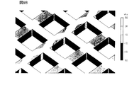
- FIG. 1 is a schematic perspective view of an example of a filtration filter 1A according to Embodiment 1 of the present invention.
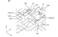
- FIG. 2 is a schematic perspective view in which a part of the discontinuous portion 14 of the filter unit 10 of FIG. 1 is enlarged.
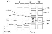
- FIG. 3 is a schematic plan view in which a part of the discontinuous portion 14 of the filter unit 10 of FIG. 1 is enlarged.
- the directions D1 and D2 in FIG. 1 indicate the circumferential direction of the filter 1A and the direction orthogonal to the circumferential direction of the filter 1A, respectively.
- the X, Y, and Z directions in FIGS. 2 and 3 indicate a horizontal direction, a vertical direction, and a thickness direction of the filtration filter 1A, respectively.
- the filtration filter 1 ⁇ / b> A is formed in a cylindrical shape provided with a first opening 2 and a second opening 3 facing the first opening 2.
- the first opening 2 and the second opening 3 face each other in the longitudinal direction (Y direction) of the filtration filter 1A.
- the circumferential direction D1 is a direction orthogonal to a direction D2 from the first opening 2 to the second opening 3 of the filtration filter 1A and surrounding the shape along the outer peripheral portion of the filtration filter 1A. .
- the circumferential direction D1 is along the outer periphery of the filtration filter 1A in a cross section when the filtration filter 1A is cut in a direction orthogonal to the direction D2 from the first opening 2 to the second opening 3 of the filtration filter 1A.
- the circumferential direction D1 means the circumferential direction of the filtration filter 1A.
- the filtration filter 1A includes the filter unit 10 and the frame unit 20.
- the filter unit 10 is formed in a hollow cylindrical shape.
- the frame portions 20 are arranged at both ends of the filter portion 10 and are formed in an annular shape.
- the filtration filter 1A includes the frame portion 20, but the frame portion 20 is not an essential component.
- the cylindrical filter 1A will be described as an example.
- the shape of the filter 1A is not limited to the cylindrical shape.
- Filtration filter 1A may have a cylindrical shape.
- filtration filter 1A is formed in a cylindrical shape by rolling a rectangular film-shaped filter having first main surface PS1 and second main surface PS2 opposed to first main surface PS1. Have been.
- the first main surface PS1 is located on the outer surface of the cylindrical filter 1A, and the second main surface PS2 is located on the inner surface of the cylindrical filter 1A.
- the filtration filter 1A is a filter used for cross-flow filtration.
- a fluid containing an object to be filtered flows inside the cylindrical shape.
- the object to be filtered is captured by the second main surface PS2 of the filter 1A, and a part of the fluid flows from the second main surface PS2 of the filter 1A toward the first main surface PS1.
- the “filtration target” means a target to be filtered among the targets included in the fluid.
- the object to be filtered may be powder or fine particles.
- the object to be filtered may be a biological substance contained in the fluid.
- the “biological substance” refers to a substance derived from an organism such as a cell (eukaryote), a bacterium (eubacteria), and a virus. Examples of cells (eukaryotes) include induced pluripotent stem cells (iPS cells), ES cells, stem cells, mesenchymal stem cells, mononuclear cells, single cells, cell clusters, planktonic cells, adherent cells, and neural cells.
- Bacteria include, for example, Escherichia coli and Mycobacterium tuberculosis.
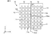
- the filter section 10 is formed of a filter base section 12 that defines a plurality of through holes 11 arranged periodically.
- the plurality of through holes 11 are arranged in a square lattice arrangement.
- the filter base portion 12 forming the filter portion 10 has at least one of a metal and a metal oxide as a main component.
- the filter base 12 may be, for example, gold, silver, copper, platinum, nickel, palladium, titanium, an alloy thereof, or an oxide thereof.
- the filter base 12 has a continuous portion 13 formed continuously in a lattice shape, and a discontinuous portion 14 formed by shifting the continuous portion 13 in a direction D2 orthogonal to the circumferential direction D1 of the filter 1A. .
- the continuous portion 13 is formed continuously in a lattice shape.
- “Continuously formed in a lattice shape” means that a portion of the filter base portion 12 extending in the circumferential direction D1 (X direction) of the filtration filter 1A is formed without an inflection point, and This means that a portion of the filter base 12 extending in the longitudinal direction (Y direction) of the filter 1A is formed without having an inflection point.
- the filter base 12 is formed integrally.
- “continuously formed in a lattice shape” means that the filter is continuously formed in the direction D2 from the first opening 2 to the second opening 3 of the filtration filter 1A, and This means that the filter 1A is formed continuously in the circumferential direction D1 along the outer periphery of the filter 1A in a cross section when the filter 1A is cut in a direction orthogonal to the direction D2 from the first opening 2 to the second opening 3.
- a plurality of through holes 11 are periodically arranged so that the Hamiltonian has a translation symmetry.
- the continuous portion 13 is such that a portion of the filter base portion 12 extending in the circumferential direction D1 of the filter 1A or a portion extending in the direction D2 orthogonal to the circumferential direction D1 has local periodicity.
- the direction D2 orthogonal to the circumferential direction D1 means a direction from the first opening 2 to the second opening 3.
- the continuous portions 13 are formed continuously in a lattice shape. Therefore, the plurality of through holes 11 defined by the filter base 12 are periodically arranged on the first main surface PS1 and the second main surface PS2 of the filter unit 10. Specifically, the plurality of through holes 11 are provided at regular intervals in a matrix in the filter unit 10.
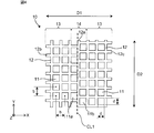
- the through hole 11 has a square shape when viewed from the first main surface PS1 side of the filter unit 10, that is, from the Z direction.
- the plurality of through holes 11 are arranged in two arrangement directions parallel to each side of the square when viewed from the first main surface PS1 side (Z direction) of the filter unit 10, that is, in the X direction and the Y direction in FIGS. They are provided at equal intervals.
- the interval between the plurality of through-holes 11 is appropriately designed according to the type (size, form, property, elasticity) or amount of the filtration object.
- the interval between the through holes 11 refers to the distance between the through holes 11 adjacent to the center of an arbitrary through hole 11 when the through hole 11 is viewed from the first main surface PS1 side of the filter unit 10. It means the distance b from the center.
- the interval b between the through holes 11 is, for example, more than 1 time and 10 times or less the one side d of the through hole 11, and preferably 3 times or less the one side d of the through hole 11.
- the aperture ratio of the filter unit 10 is 10% or more, and preferably, the aperture ratio is 25% or more. With such a configuration, the resistance of the passage of the fluid to the filter unit 10 can be reduced.
- the aperture ratio is calculated by (area occupied by through-hole 11) / (projected area of first main surface PS1 assuming that through-hole 11 is not vacant).
- the thickness of the filter portion 10 is preferably 0.1 to 10 times the size (one side d) of the through hole 11. More preferably, the thickness of the filter portion 10 is larger than 0.5 times the size (one side d) of the through hole 11 and equal to or smaller than 10 times. With such a configuration, the resistance of the filtration filter 1A to the fluid can be reduced. As a result, the stress on the filtration target can be reduced.
- the second main surface PS2 that is in contact with the fluid containing the object to be filtered preferably has a small surface roughness.
- the surface roughness means the average value of the difference between the maximum value and the minimum value measured by the stylus type step meter at any five points on the second main surface PS2.
- the surface roughness is preferably smaller than the size of the object to be filtered, and more preferably smaller than half the size of the object to be filtered.
- the openings of the plurality of through holes 11 on the second main surface PS2 of the filter unit 10 are formed on the same plane (XY plane).
- the filter base portion 12 which is a portion of the filter portion 10 where the through-hole 11 is not formed, is connected and integrally formed.
- the through-hole 11 communicates with the opening on the first main surface PS1 side and the opening on the second main surface PS2 through a continuous wall surface. Specifically, the through hole 11 is provided such that an opening on the first main surface PS1 side can be projected onto an opening on the second main surface PS2 side. That is, when the filter unit 10 is viewed from the first main surface PS1, the through hole 11 is provided such that the opening on the first main surface PS1 side overlaps the opening on the second main surface PS2 side.
- the shape (cross-sectional shape) of the through hole 11 projected on a plane perpendicular to the first main surface PS1 of the filter unit 10 is a rectangle.
- the cross-sectional shape of the through-hole 11 is a rectangle in which the length of one side in the circumferential direction D1 of the filtration filter 1A is longer than the length of one side in the thickness direction of the filtration filter 1A.
- the cross-sectional shape of the through hole 11 is not limited to a rectangle, and may be a tapered shape such as a parallelogram or a trapezoid, a symmetric shape, or an asymmetric shape. .
- the discontinuous portion 14 is formed by shifting a part of the continuous portion 13 in a direction D2 orthogonal to the circumferential direction D1 of the filtration filter 1A. Specifically, a portion of the continuous portion 13 extending in the horizontal direction (X direction) of the filtration filter 1A is shifted in the vertical direction (Y direction) of the filtration filter 1A.
- the discontinuous portion 14 means that a portion of the filter base portion 12 extending in the circumferential direction D1 of the filter 1A or a portion extending in the direction D2 orthogonal to the circumferential direction D1 has an inflection point. Means the part forming.
- the filter base portion 12 includes a first filter base portion 12a that extends in a discontinuous portion 14 in a direction D2 (Y direction) orthogonal to the circumferential direction D1 (X direction) of the filter 1A.
- the filter base portion 12 includes a plurality of second filter base portions 12b connected to one side of the first filter base portion 12a in the circumferential direction D1 (X direction) of the filter 1A, and a circumferential direction D1 of the filter 1A.
- a plurality of third filter base portions 12c connected to the other side of the first filter base portion 12a in the (X direction).
- the plurality of second filter bases 12b and the plurality of third filter bases 12c are formed integrally.
- a plurality of first connection portions 15 to which the plurality of second filter base portions 12b and the first filter base portion 12a are connected, a plurality of third filter base portions 12c, and the first filter base portion 12a are connected to each other.
- the plurality of first connection portions 15 and the plurality of second connection portions 16 are separated from each other in the first filter base portion 12a. Specifically, the first connection portion 15 is arranged between two adjacent second connection portions 16. In other words, each of the plurality of first connection portions 15 is arranged between the plurality of adjacent second connection portions 16.
- the plurality of first through holes 11a and the plurality of second through holes 11b adjacent to the plurality of first through holes 11a are arranged such that the arrangement of the through holes is the circumferential direction D1 of the filter 1A.
- a direction D2 (Y direction) orthogonal to are shifted in a direction D2 (Y direction) orthogonal to.
- the plurality of first through holes 11a and the plurality of second through holes 11b are each orthogonal to the height direction (Y direction) of the filtration filter 1A, that is, the circumferential direction D1 of the filtration filter 1A, at the discontinuous portion 14. It is arranged in the direction D2.
- the filter 1A forms the discontinuous portion 14 by shifting a part of the continuous portion 13 in the direction D2 (Y direction) orthogonal to the circumferential direction D1 (X direction) of the filter 1A. .
- the number of connecting portions to which the filter base portion 12 is connected can be increased as compared with the continuous portion 13.
- the connecting portion in the continuous portion 13 includes a portion of the filter base portion 12 extending in the horizontal direction (X direction) of the filtration filter 1A and a portion of the filter base portion 12 extending in the vertical direction (Y direction) of the filtration filter 1A. Are the parts that are crossed and connected.
- the connection part in the discontinuous part 14 means the first connection part 15 and the second connection part 16.
- the discontinuous portion 14 stress is more likely to be concentrated than in the continuous portion 13 because the connection portion is formed more than in the continuous portion 13. For this reason, the discontinuous portion 14 is more likely to be broken or deformed when an external force is applied than the continuous portion 13. That is, the non-continuous portion 14 can be cut more easily than the continuous portion 13. Further, the discontinuous portion 14 has a strength that is not destroyed by the force of the fluid flowing during filtration. As described above, the filtration filter 1A can be easily cut by applying a force from the outside while maintaining strength enough to withstand filtration. As a result, in the filtration filter 1A, after the filtration is completed, the discontinuous portion 14 is cut by applying an external force, and the filtration target captured by the filtration filter 1A can be easily observed.
- the width of the first filter base portion 12 a forming the discontinuous portion 14 is equal to the width of the filter base portion 12 forming the continuous portion 13.
- the width of the first filter base portion 12a extending in the direction D2 (Y direction) orthogonal to the circumferential direction D1 (X direction) of the cylindrical filtration filter 1A is equal to the width of the continuous portion 13. It is equal to the width of the filter base 12 to be formed.
- “equal” includes an error within a range of 10%.
- the frame portion 20 is a member arranged at each end of the cylindrical filter portion 10.
- the frame portion 20 is formed in an annular shape when viewed from one end or the other end of the cylindrical filter portion 10.
- the frame section 20 may display filter information (for example, dimensions of the through hole 11). Thereby, the hole size of the through-hole 11 can be grasped without performing length measurement again.
- the material forming the frame portion 20 is the same as the material forming the filter portion 10 (the filter base portion 12).
- the cylindrical filtration filter 1A has a diameter of 12 mm, a height of 22 mm, and a thickness of 2 ⁇ m.
- One side of the square through hole 11 is 6 ⁇ m.
- the width of the filter base 12 is 2.5 ⁇ m.
- the filtration filter 1A is not limited to these dimensions, and may be manufactured in other dimensions.
- FIG. 4 shows an example of a cutting method of the filtration filter 1A according to the first embodiment of the present invention.
- the cylindrical filtration filter 1A can be easily cut. .
- For cutting for example, use tweezers and a scalpel.
- FIGS. 5A to 5E are schematic diagrams illustrating an example of steps of a method of manufacturing the filtration filter 1A according to the first embodiment of the present invention.
- 5A to 5E show steps before the filtration filter 1A is processed into a cylindrical shape.
- a copper thin film 32 having a thickness of 1.5 ⁇ m is formed on a substrate 31 such as silicon.
- the copper thin film 32 can be formed by vapor deposition or sputtering.
- a 0.5 ⁇ m-thick Ti intermediate layer 33 is formed to improve the adhesion between the substrate 31 and the copper thin film 32.
- a resist is applied on the copper thin film 32 by spin coating and dried to form a resist film having a thickness of 2 ⁇ m.
- the resist film 34 was exposed and developed, and the resist film 34 corresponding to the filter base 12 was removed.
- the hole shape is a square.
- the filter base portion 12 made of the Ni plating film 35 is formed by electroforming on the portion where the resist film 34 has been removed. Subsequently, by removing the resist film 34 using an organic solvent, the filtration filter 1A before being processed into a cylindrical shape is manufactured.
- the filter 1A When processing into a cylindrical shape, the filter 1A alone may be deformed by a fluid, so it is necessary to improve the mechanical strength of the filter. Therefore, the reinforcing layer 36 is formed on the outer peripheral portion and the central line portion of the filtration filter 1A.
- the thickness of the reinforcing layer 36 is 20 ⁇ m, and in the portion arranged in the filter base 12, square through-holes 11 of 290 ⁇ m on a side are arranged in a square lattice at intervals of 10 ⁇ m.
- a resist film 34 having a thickness of 30 ⁇ m is formed in the same manner as in FIGS. 5A to 5C, and the resist film 34 at the outer peripheral portion and the central line portion of the filter 1A is removed by exposure and development. .
- a reinforcing layer 36 made of a Ni plating film is formed by electroforming at a position where the resist film 34 has been removed.
- a filtration filter 1A having a side of 6 ⁇ m on one side of the through hole 11 and an aperture ratio of 50% is manufactured.
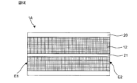
- the filtration filter 1A is a film-like filter having a rectangular shape.
- the frame portion 20 and the support portion 21 of the filtration filter 1A are formed of the reinforcing layer 36.
- the reinforcing layer 36 is not an essential component.
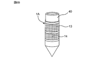
- FIGS. 6A and 6B are schematic views of an example of a method for forming the discontinuous portion 14.
- FIG. 6A and 6B are schematic views of an example of a method for forming the discontinuous portion 14.
- the filter 1A is wound around the outer periphery of a cylindrical container 40 formed of polyacetal resin.
- the container 40 is a bottomed container.
- the side wall of the container 40 around which the filtration filter 1A is wound is open.
- the container 40 is an example of a container used for filtration.
- the container 40 is not limited to this.
- a tape is attached to the outer peripheral portion of the membrane-shaped filtration filter 1A having one end E1 and the other end E2, and then the filtration filter 1A is wound around the container 40 to be rolled into a cylindrical shape and fixed.
- a 50 ⁇ m-thick double-sided tape (Rintech Co., Ltd.) is applied to the outer peripheral portion of the filtration filter 1 ⁇ / b> A with a thin acrylic adhesive based on a polyester film, according to the width of the outer peripheral portion in the X and Y directions.
- Attach tack liner (TL-450S-16).
- the other end E2 side of the outer peripheral portion has a gap of 3 mm in the longitudinal direction (X direction) where no double-sided tape is attached.
- the filter 1A to which the double-sided tape is attached is wound around the container 40, thereby being rolled into a cylindrical shape and fixed.
- one end E1 and the other end E2 of the filter 1A are joined with an epoxy resin using an optical microscope and a micromanipulator. Specifically, bonding is performed by applying an epoxy resin to a bonding surface between one end E1 and the other end E2 and a gap between the outer peripheral portion of the filtration filter 1A and the container 40. At this time, the one end E1 and the other end E2 are shifted and joined so that the arrangement of the plurality of through holes 11 is discontinuous. As a result, the discontinuous portion 14 is formed at the joint between the one end E1 and the other end E2.
- the magnification of the optical microscope is set to 1000 times, and while looking through the microscope, the other end E2 side of the outer peripheral portion on which the double-sided tape is not attached is moved using a micromanipulator to align the grid at the joint. I do. After the positioning, it is temporarily fixed with a tape, and is joined by applying an epoxy resin to a joint surface between the one end E1 and the other end E2 and a gap between the outer periphery of the filter 1A and the container 40.
- the discontinuous portion 14 of the filtration filter 1A is cut using tweezers and a scalpel. Specifically, the epoxy resin joining one end E1 and the other end E2 of the filtration filter 1A is cut off, and the discontinuous portion 14 is slowly peeled off the container 40 from the outer periphery using tweezers. Accordingly, the cylindrical filtration filter 1A is cut at the discontinuous portion 14, and the filtration target captured on the second main surface PS2 of the filtration filter 1A can be directly observed with a microscope. In particular, when the object to be filtered is a cell, the object to be filtered can be observed without damaging the cell.
- Stress analysis simulation A description will be given of the result of a stress analysis simulation performed on the stress generated in the discontinuous portion 14 of the filter unit 10 using Femtet manufactured by Murata Manufacturing Co., Ltd.
- FIG. 7 is a schematic enlarged view showing an example of the analysis model used for the stress analysis simulation.
- the filtration filter used in the analysis model has a plurality of square through holes 11 arranged in a square lattice array.
- One side L1 of the through hole 11 of the filter of the analysis model is 12 ⁇ m, and the depth L2 is 5 ⁇ m.
- the width L3 of the filter base 12 is 5 ⁇ m.
- the constituent material of the filter of the analysis model is Ni.
- the shift S1 is determined from the point CP1 where the extension line L12 extending the lower side L11 of the second through-hole 11b in the discontinuous portion 14 in the lateral direction (X direction) of the filter and the side L21 of the first through-hole 11a intersect. It means the distance to the lower side L22 of one through hole 11a.
- FIG. 8A shows an example of a result of a stress analysis simulation of the analysis model of Comparative Example 1.
- FIG. 8B is an enlarged view of a Z1 portion of Comparative Example 1 of FIG. 8A.
- FIG. 9A shows an example of a stress analysis simulation result of the analysis model of the first embodiment.
- FIG. 9B is an enlarged view of a Z2 portion of the first embodiment in FIG. 9A.
- stress is generated in a wider range in the discontinuous portion 14 of the first embodiment than in the first comparative example. This is because the discontinuous portion 14 of the first embodiment has a larger number of connection portions of the filter base 12 than the comparative example 1. Since stress is likely to be generated at the connection portion of the filter base portion 12, it is considered that the number of locations where the stress is generated is larger in Example 1 than in Comparative Example 1.
- FIG. 10 shows a portion where the stress analysis was performed at the discontinuous portion 14 of the filter of the analysis model.
- FIG. 11 shows a detailed position where the stress analysis is performed.
- the stress analysis was performed along the analysis line CL2 passing through one side of the first through hole 11a facing the second through hole 11b.
- the filter of the analysis model since the plurality of through holes 11 are periodically formed, it is considered that the stress distribution has periodicity. Therefore, a period between two through holes 11aa and 11ab adjacent in the vertical direction (Y direction) of the filter is regarded as one cycle.
- five analysis positions P1 to P5 were provided between the two through holes 11aa and 11ab on the analysis line CL2, and the stress at each analysis position was analyzed.
- the through hole 11aa is arranged below the through hole 11ab.
- the analysis position P1 is located at the center of one side of the through hole 11aa passing through the analysis line CL2.
- the analysis position P2 is located above the analysis position P1 and at a corner of the through hole 11aa.
- the analysis position P3 is located on the filter base 12a between the through hole 11aa and the through hole 11ab adjacent to the through hole 11aa, and is located at an equal distance from the corner of the through hole 11aa and the corner of the through hole 11ab. I do.
- the analysis position P4 is information on the analysis position P3, and is located at a corner of the through hole 11ab arranged on the through hole 11aa side.
- the analysis position P5 is located at the center of one side of the through hole 11ab passing through the analysis line CL2.
- Comparative Example 2 and Examples 2 to 9 were used using the misalignment of the first through-hole 11a and the second through-hole 11b as a parameter.
- Comparative Example 2 has a deviation of 0% and has no discontinuous portion 14.
- the deviations were 1%, 5%, 10%, 20%, 40%, 60%, 80% and 100%, respectively.
- FIG. 12A shows a schematic configuration of the analysis model of Comparative Example 2.
- FIG. 12B shows a schematic configuration of the analysis model of the ninth embodiment.
- Comparative Example 2 has a deviation of 0% and has no discontinuous portion 14.
- a deviation of 0% means that all the through holes 11 are arranged in a square lattice arrangement.
- the deviation is 100%, and the first through-hole 11 a and the second through-hole 11 b are the most displaced in the discontinuous portion 14.
- the ratio of deviation is changed by sequentially increasing S1 and decreasing S2.
- FIG. 13 shows an example of the stress analysis results of Comparative Example 2 and Examples 2 to 9.
- the maximum principal stress near the analysis positions P2 and P4 is higher than in Comparative Example 2.
- the number of connection portions of the filter base portion 12 in the discontinuous portion 14 is larger than that in Comparative Example 2, stress is easily concentrated on the connection portion, and the connection portion is easily broken.
- the value of the maximum principal stress decreases as the ratio of the displacement increases. From this, it is conceivable that cracks and chips are unlikely to occur near the analysis position P3.
- the connection of the filter base 12 in the discontinuous portion 14 is smaller than when the displacement is 0%.
- the stress in the part increases, and it is easy to break.
- connection of the filter base portion 12 in the discontinuous portion 14 is displaced on the longitudinal end face of the filter. Therefore, when cutting using a scalpel and tweezers after filtration, since there is a handle and a gap, compared with Comparative Example 2, it is possible to perform cutting with a reduced probability of successful cutting or damage to the surface. it can.
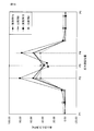
- FIG. 14 is a diagram showing the relationship between the maximum principal stresses of Examples 2 to 9 based on Comparative Example 2.
- the maximum principal stresses of Comparative Example 2 and Examples 2 to 9 at the analysis position P4 are used.
- the values of the maximum principal stress of Examples 3 to 9 are the values of Example 3, Example 4, Example 5, Example 6, Example 7, Example 9, and Example 8 increase in this order.
- the maximum principal stress is larger than that in Example 9 although the deviation is smaller than that in Example 9.
- the maximum principal stress of the configuration with the deviation of 0% is used as a reference, the maximum principal stress of the configuration with the deviation of 5% to 100% is larger than that of the configuration with the deviation of 0%. , And the maximum principal stress is the largest in a configuration in which the deviation is 80%.
- FIG. 15A shows an example of a state where filtration is performed using the filtration filter 1A according to the first embodiment of the present invention.
- the filtration filter 1A is attached to a side wall of a cylindrical container 41.
- the container 41 to which the filtration filter 1A is attached is arranged along a direction D4 orthogonal to the direction of gravity D3.
- the container 41 is arranged so that the inflow port 42 of the fluid containing the object to be filtered faces the direction D4 orthogonal to the direction of gravity D3. Accordingly, the fluid flows in the direction inside the filter 1A in the direction D4, and also flows in parallel along the second main surface PS2 of the filter 1A.
- the stress applied to the discontinuous portion 14 is mainly dominated by the load due to gravity and the shear stress due to friction of the fluid.
- the influence of gravity is large. Therefore, it is preferable that the discontinuous portion 14 is disposed above the filtration filter 1A in the direction of gravity D3. Thereby, it is possible to prevent the load in the gravity direction D3 from being applied to the discontinuous portion 14 and to suppress the discontinuous portion 14 from being broken during the filtration.
- FIG. 15B is a diagram showing another example of a state where filtration is performed using the filtration filter 1A according to the first embodiment of the present invention.
- a cylindrical container 41 to which the filtration filter 1A is attached may be arranged along the direction of gravity D3.
- the container 41 is arranged with the inlet 42 of the fluid containing the filtration target facing upward.
- the fluid flows in the same direction D5 as the gravity direction D3, and also flows in parallel along the second main surface PS2 of the filter 1A.
- the discontinuity of the discontinuous portion 14 during filtration can be suppressed.
- the wall surface of the connection part of the filter base part 12 in the discontinuous part 14 is arranged along the direction in which the fluid flows. Therefore, the shear force applied to the discontinuous portion 14 is dominated by the influence of the flow viscosity.
- the shear stress applied in the immediate vicinity of the wall is determined by the viscosity and the velocity gradient. Since the velocity gradient can be regarded as the same straight line as the laminar flow only in the vicinity of the wall surface, it is determined by the flow velocity and the diameter of the filter 1A.
- the viscosity of a liquid such as water generally used as a fluid is as small as several mPa / s or less.
- the shear stress applied to the wall surface of the cylindrical filtration filter 1A having a radius of 6 mm When the shear stress applied to the wall surface of the cylindrical filtration filter 1A having a radius of 6 mm is calculated, it becomes about 42 mPa when 20 ° C. water is flowed at 5 ⁇ 10 ⁇ 1 m / s. Since the strength of the epoxy resin is indicated in units of several hundred MPa, it is considered that the possibility of breaking the discontinuous portion 14 at the time of filtration is extremely low if the epoxy resin is sufficiently cured even if it is applied thinly.
- the filter 1A may be used in a state where the filter 1A is inclined with respect to the direction of gravity D3.
- the filtration filter 1A is a cylindrical filter, and includes a filter base portion 12 defining a plurality of through holes 11 arranged in a square lattice arrangement.
- the filter base portion 12 includes a filter D1A in a direction D2 from the first opening 2 to the second opening 3 of the filtration filter 1A and a direction D2 orthogonal to the direction D2 from the first opening 2 to the second opening 3 in the filtration filter 1A.
- a continuous portion 13 formed continuously in the circumferential direction D1 along the outer periphery of the filtration filter 1A in a cross section when the filter is cut, and a part of the continuous portion 13 is changed from the first opening 2 to the second opening 3 of the filtration filter 1A.
- the filter 1A is not broken by the force of the fluid during the cross-flow filtration, and can be easily cut by applying an external force after the filtration is completed. it can. As a result, it is possible to easily observe the filtration target captured inside the filtration filter 1A.
- the filtration filter 1A can be easily cut by applying a force from the outside while maintaining the strength capable of withstanding the filtration in the cylindrical filter.
- the filter base 12 has a first filter base 12a that extends in the discontinuous portion 14 in a direction D2 orthogonal to the circumferential direction D1 of the filtration filter 1A.
- the filter base portion 12 includes a plurality of second filter base portions 12b connected to one side of the first filter base portion 12a in the circumferential direction D1 of the filter 1A, and a first filter in the circumferential direction D1 of the filter 1A.
- a plurality of third filter base portions 12c connected to the other side of the base portion 12a.
- a plurality of first connection portions 15 where the plurality of second filter base portions 12b and the first filter base portion 12a are connected, and a plurality of where the plurality of third filter base portions 12c and the first filter base portion 12a are connected. Is shifted in a direction D2 orthogonal to the circumferential direction D1 of the filtration filter 1A.
- first connection portions 15 and a plurality of second connection portions 16 that are separated from each other are formed in the first filter base portion 12a that forms the discontinuous portion 14.
- the number of connection portions can be increased as compared with the continuous portion 13, and stress is easily generated.
- the filter 1A can be more easily cut by applying a force from the outside while maintaining strength enough to withstand filtration in the cylindrical filter.
- Each of the plurality of first connection portions 15 is disposed between a plurality of adjacent second connection portions 16. With such a configuration, when a force is externally applied to the filtration filter 1A, it can be cut more easily.
- the width of the first filter base portion 12 a forming the discontinuous portion 14 is equal to the width of the filter base portion 12 forming the continuous portion 13.
- the filtration filter 1A is a membrane filter having one end E1 and the other end E2, and is formed in a cylindrical shape by joining the one end E1 and the other end E2.
- the discontinuous portion 14 is formed at a joining portion where one end E1 and the other end E2 are joined. With such a configuration, the discontinuous portion 14 can be easily formed, and the filter 1A can be more easily cut by applying an external force.
- the filter base 12 mainly contains at least one of a metal and a metal oxide.
- the discontinuous portion 14 is hardly broken by the force of the fluid filtration, and is easily cut when an external force is applied. That is, the filtration filter 1A can be easily cut by applying an external force while improving the mechanical strength.
- the distance between the through hole 11a positioned so as to straddle the boundary surface and the adjacent through hole 11b is adjacent at a position other than the boundary surface. It can be longer than the distance between the two through holes 11.
- the through-holes 11 and the filter gas portion 12 are regularly arranged. However, since the distance between the adjacent through-holes 11a and 11b can be increased due to displacement at the boundary surface, the distance between the adjacent through-holes 11a and 11b can be increased.
- the filter base portion 12a thin the distance between the boundary surface and the adjacent through-hole 11 in the other region can be equalized. With such a configuration, the aperture ratio is increased, and the filtration efficiency can be increased.
- the first embodiment is advantageous when the object to be filtered is a cell and the fluid is a cell suspension.
- the filtration filter 1A is formed in a cylindrical shape by joining one end E1 and the other end E2, but the present invention is not limited to this.
- the filtration filter 1A may be formed integrally.
- the continuous portion 13 and the discontinuous portion 14 may be formed integrally.
- the pattern in which the continuous portion 13 and the non-continuous portion 14 are connected is put together in the same mask, and exposure and development are performed, so that the continuous portion 13 and the non-continuous portion 14 are integrated.
- the mold of the filtration filter 1A can be integrally formed.
- one end E1 and the other end E2 are joined with an epoxy resin in the filtration filter 1A
- the present invention is not limited to this.
- the one end E1 and the other end E2 may be joined by welding.
- the discontinuous portion 14 may be formed in a direction crossing in the circumferential direction D1 of the filtration filter 1A.
- the discontinuous portion 14 may be formed obliquely in the circumferential direction D1 of the filtration filter 1A.
- one or more discontinuous portions 14 may be formed. For example, if it is desired to separate the filtration filter 1A for a reason such as analysis in one field of view of a microscope, reculturing in 6 wells, etc. It can be cut into filtration filters of any size. Thus, one or more discontinuous portions 14 may be formed. As described above, the discontinuous portions 14 may be formed at a plurality of locations.
- the cylindrical filtration filter 1A is cut, and the cut filtration filter is placed on an optical microscope to observe an object to be filtered.
- the present invention is not limited to this.
- the cylindrical filtration filter 1A may be cut to collect the filtration target.
- the filtration filter 1A has a cylindrical shape, but the present invention is not limited to this.
- the filtration filter 1A may have a cylindrical shape with a circular, elliptical, or polygonal cross section cut in a direction perpendicular to the direction D2.
- the second embodiment differs from the first embodiment in that the discontinuous portion has a flat plate portion.
- FIG. 16 is a schematic configuration diagram of an example of a part of the filtration filter 1B according to the second embodiment of the present invention.
- the discontinuous portion 14a has the flat plate portion 17 extending in the direction D2 orthogonal to the circumferential direction D1 of the filter 1B.
- the flat plate portion 17 is obtained by increasing the width of the first filter base portion 12a of the first embodiment. That is, the flat plate portion 17 is a part of the filter base portion 12. The flat plate portion 17 is formed between the plurality of first through holes 11a and the plurality of second through holes 11b formed by the discontinuous portion 14a. Further, the width of the flat plate portion 17 means the length of the filtration filter 1B in the lateral direction (X direction). The thickness of the flat plate portion 17 is equal to the thickness of the filter base portion 12. The flat plate portion 17 is formed of the same material as the filter base portion 12.
- the width of the flat plate portion 17 is 25 ⁇ m.
- the first through-holes 11a and the second through-holes 11b are arranged so as to be shifted from each other with the flat plate portion 17 interposed therebetween. That is, a plurality of second filter base portions 12b are connected to one side of the flat plate portion 17 in the circumferential direction D1 of the filtration filter 1B. A plurality of third filter base portions 12c are connected to the other side of the flat plate portion 17 in the circumferential direction D1 of the filtration filter 1B.
- Stress analysis simulation A description will be given of the result of an analysis simulation performed on the stress generated in the discontinuous portion 14a using Femtet manufactured by Murata Manufacturing Co., Ltd.
- a stress analysis was performed using an analysis model having the same configuration as that of the filtration filter 1B.
- the conditions for the stress analysis are the same as in the first embodiment. Specifically, the shifts S1 and S2 between the first through-hole 11a and the second through-hole 11b in the discontinuous portion 14a are adjusted, and Comparative Example 3 in which there is no shift and Examples 10 to 14 in which there is a shift are provided. , And the stress analysis was performed. Comparative Example 3 has the flat plate portion 17, but the deviation between the first through hole 11a and the second through hole 11b is 0%, and all the through holes 11 are arranged in a square lattice arrangement. Have been. In Examples 10 to 14, in the filtration filter 1B, the deviation between the first through hole 11a and the second through hole 11b is set to 20%, 40%, 60%, 80%, and 100%, respectively.
- FIG. 17 shows an example of the stress analysis results of Comparative Example 3 and Examples 10 to 14.
- the maximum principal stresses of Examples 12 to 14 are larger than the maximum principal stress of Comparative Example 3.
- the maximum principal stress is larger than the case where the displacement is 0%.
- the comparative example 3 is compared with the example 14, the difference between the maximum principal stresses at the analysis positions P2 and P4 is small.
- Comparative Example 4 is a filter that does not have the flat plate portion 17 and has 0% displacement between the first through hole 11a and the second through hole 11b.
- Comparative Example 5 is a filter having the flat plate portion 17 but having a deviation of 0%.
- Example 15 is a filtration filter 1A having no flat portion 17 and having a displacement of 100%.
- Example 16 is a filtration filter 1B having a flat plate portion 17 and a deviation of 100%.
- FIG. 18 shows an example of stress analysis results of Comparative Examples 4 to 5 and Examples 15 to 16. Focusing on the maximum principal stress at the analysis positions P2 and P4, the maximum principal stress increases in the order of Comparative Example 6, Comparative Example 5, Example 16, and Example 15.
- the discontinuous portion 14a has the flat plate portion 17 extending in the direction D2 orthogonal to the circumferential direction D1 of the cylindrical filtration filter 1B.
- the width of the flat plate portion 17 is larger than the width of the filter base portion 12.
- the adhesive surface between the flat plate portion 17 and the container 40 can be easily peeled off.
- the joining of the discontinuous portion 14a can be weakened, the discontinuous portion 14a of the filtration filter 1B can be easily cut when an external force is applied.
- the filtration filter of the present invention allows the collected matter to be easily observed, it is useful in fields such as drug efficacy investigation using cells and production of regenerative medicine.
Landscapes
- Chemical & Material Sciences (AREA)
- Life Sciences & Earth Sciences (AREA)
- Health & Medical Sciences (AREA)
- Engineering & Computer Science (AREA)
- Bioinformatics & Cheminformatics (AREA)
- Organic Chemistry (AREA)
- Zoology (AREA)
- Wood Science & Technology (AREA)
- Chemical Kinetics & Catalysis (AREA)
- Biotechnology (AREA)
- Genetics & Genomics (AREA)
- General Engineering & Computer Science (AREA)
- Biochemistry (AREA)
- Biomedical Technology (AREA)
- General Health & Medical Sciences (AREA)
- Microbiology (AREA)
- Molecular Biology (AREA)
- Sustainable Development (AREA)
- Geology (AREA)
- Virology (AREA)
- Tropical Medicine & Parasitology (AREA)
- Medicinal Chemistry (AREA)
- Filtering Materials (AREA)
- Filtration Of Liquid (AREA)
Abstract
外部の力を加えることによって容易に切断することができる濾過フィルタを提供する。本発明の濾過フィルタは、第1開口と前記第1開口に対向する第2開口とが設けられた筒形状の濾過フィルタであって、正方格子配列で配置される複数の貫通孔を画定するフィルタ基体部備え、前記フィルタ基体部は、前記濾過フィルタの前記第1開口から前記第2開口に向かう方向と、前記濾過フィルタの前記第1開口から前記第2開口に向かう方向に直交する方向で前記濾過フィルタを切断したときの断面において前記濾過フィルタの外周に沿う周方向と、に連続して形成される連続部と、前記連続部の一部を前記濾過フィルタの前記第1開口から前記第2開口に向かう方向にずらして形成される非連続部と、を有する。
Description
本発明は、濾過フィルタに関する。
フィルタとして、例えば、円筒形状を有するフィルタが知られている(例えば、特許文献1参照。)。
特許文献1のフィルタは、縦方向の重合部を溶接している内側の筒状金網と、金属繊維のフェルトシートを内側の筒状金網に所定の厚みに巻き付け且つ耐熱性樹脂を含浸・乾燥させたフィルタ本体と、縦方向の重合部を溶接している外側の筒状金網とで構成されている。
近年、筒形状を有する濾過フィルタにおいて、外部の力を加えることによって容易に切断することができる濾過フィルタが求められている。
本発明は、外部の力を加えることによって容易に切断することができる濾過フィルタを提供することを目的とする。
本発明の一態様の濾過フィルタは、
第1開口と前記第1開口に対向する第2開口とが設けられた筒形状の濾過フィルタであって、
正方格子配列で配置される複数の貫通孔を画定するフィルタ基体部を備え、
前記フィルタ基体部は、
前記濾過フィルタの前記第1開口から前記第2開口に向かう方向と、前記濾過フィルタの前記第1開口から前記第2開口に向かう方向に直交する方向で前記濾過フィルタを切断したときの断面において前記濾過フィルタの外周に沿う周方向と、に連続して形成される連続部と、
前記連続部の一部を前記濾過フィルタの前記周方向と直交する方向にずらして形成される非連続部と、
を有する。
第1開口と前記第1開口に対向する第2開口とが設けられた筒形状の濾過フィルタであって、
正方格子配列で配置される複数の貫通孔を画定するフィルタ基体部を備え、
前記フィルタ基体部は、
前記濾過フィルタの前記第1開口から前記第2開口に向かう方向と、前記濾過フィルタの前記第1開口から前記第2開口に向かう方向に直交する方向で前記濾過フィルタを切断したときの断面において前記濾過フィルタの外周に沿う周方向と、に連続して形成される連続部と、
前記連続部の一部を前記濾過フィルタの前記周方向と直交する方向にずらして形成される非連続部と、
を有する。
本発明によれば、外部の力を加えることによって容易に切断することができる濾過フィルタを提供することができる。
(本発明に至った経緯)
近年、筒形状の濾過フィルタを用いて濾過対象物を含む流体をクロスフロー濾過方式で濾過した後、濾過フィルタに捕捉された濾過対象物を観察したいという要望が高まっている。例えば、濾過フィルタを用いて濾過を行った後、濾過対象物を捕捉した濾過フィルタを光学顕微鏡にセットし、濾過対象物を観察したいという要望がある。
近年、筒形状の濾過フィルタを用いて濾過対象物を含む流体をクロスフロー濾過方式で濾過した後、濾過フィルタに捕捉された濾過対象物を観察したいという要望が高まっている。例えば、濾過フィルタを用いて濾過を行った後、濾過対象物を捕捉した濾過フィルタを光学顕微鏡にセットし、濾過対象物を観察したいという要望がある。
しかしながら、筒形状の濾過フィルタにおいては、濾過フィルタの内部に濾過対象物が捕捉されるため、濾過フィルタに捕捉された濾過対象物を観察することが困難である。このため、濾過フィルタを用いて濾過を行った後、濾過フィルタに外部の力を加えて切断し、濾過フィルタ内部に捕捉された濾過対象物を観察することになる。
このような背景の下、筒形状の濾過フィルタにおいては、濾過を行っているときの流体の力で破壊されず、且つ濾過が終了した後に外部から力を加えることで容易に切断できることが求められている。
そこで、本発明者らは、濾過に耐え得る強度を維持しつつ、外部から力を加えることで容易に切断することができる筒形状のフィルタを提供すべく、以下の発明に至った。
本発明の一態様の濾過フィルタは、
第1開口と前記第1開口に対向する第2開口とが設けられた筒形状の濾過フィルタであって、
正方格子配列で配置される複数の貫通孔を画定するフィルタ基体部を備え、
前記フィルタ基体部は、
前記濾過フィルタの前記第1開口から前記第2開口に向かう方向と、前記濾過フィルタの前記第1開口から前記第2開口に向かう方向に直交する方向で前記濾過フィルタを切断したときの断面において前記濾過フィルタの外周に沿う周方向と、に連続して形成される連続部と、
前記連続部の一部を前記濾過フィルタの前記周方向と直交する方向にずらして形成される非連続部と、
を有する。
第1開口と前記第1開口に対向する第2開口とが設けられた筒形状の濾過フィルタであって、
正方格子配列で配置される複数の貫通孔を画定するフィルタ基体部を備え、
前記フィルタ基体部は、
前記濾過フィルタの前記第1開口から前記第2開口に向かう方向と、前記濾過フィルタの前記第1開口から前記第2開口に向かう方向に直交する方向で前記濾過フィルタを切断したときの断面において前記濾過フィルタの外周に沿う周方向と、に連続して形成される連続部と、
前記連続部の一部を前記濾過フィルタの前記周方向と直交する方向にずらして形成される非連続部と、
を有する。
このような構成により、筒形状の濾過フィルタにおいて、外部から力を加えることで容易に切断することができる。
前記フィルタ基体部は、前記非連続部において前記濾過フィルタの前記第1開口から前記第2開口に向かう方向に延びる第1フィルタ基体部と、前記濾過フィルタの前記周方向において前記第1フィルタ基体部の一方側に接続される複数の第2フィルタ基体部と、前記濾過フィルタの前記周方向において前記第1フィルタ基体部の他方側に接続される複数の第3フィルタ基体部と、を有し、
前記複数の第2フィルタ基体部と前記第1フィルタ基体部とが接続される複数の第1接続部と、前記複数の第3フィルタ基体部と前記第1フィルタ基体部とが接続される複数の第2接続部とは、前記濾過フィルタの前記第1開口から前記第2開口に向かう方向にずれていてもよい。
前記複数の第2フィルタ基体部と前記第1フィルタ基体部とが接続される複数の第1接続部と、前記複数の第3フィルタ基体部と前記第1フィルタ基体部とが接続される複数の第2接続部とは、前記濾過フィルタの前記第1開口から前記第2開口に向かう方向にずれていてもよい。
このような構成により、非連続部を形成する第1フィルタ基体部において、濾過フィルタの周方向に延びる複数の第2フィルタ基体部及び複数の第3フィルタ基体部のそれぞれで接続点を形成している。これにより、非連続部において応力を発生させ易くし、濾過フィルタをより容易に切断することができる。
前記複数の第1接続部のそれぞれは、隣接する前記複数の第2接続部の間にそれぞれ配置されてもよい。
このような構成により、筒形状の濾過フィルタにおいて、外部から力を加えることでより容易に切断することができる。
前記第1フィルタ基体部の幅は、前記連続部を形成するフィルタ基体部の幅と等しくてもよい。
このような構成により、筒形状の濾過フィルタにおいて、外部から力を加えることで更に容易に切断することができる。
前記濾過フィルタは、一端と他端とを有する膜状のフィルタであり、前記一端と前記他端とを接合することによって筒形状に形成され、
前記非連続部は、前記一端と前記他端とが接合される接合部に形成されていてもよい。
前記非連続部は、前記一端と前記他端とが接合される接合部に形成されていてもよい。
このような構成により、容易に非連続部を形成することができると共に、筒形状の濾過フィルタにおいて、外部から力を加えることで更に容易に切断することができる。
前記フィルタ基体部は、金属及び金属酸化物のうち少なくともいずれかを主成分としてもよい。
このような構成により、筒形状の濾過フィルタにおいて、機械強度を向上させつつ、外部から力を加えることで容易に切断することができる。
以下、本発明に係る実施の形態1について、添付の図面を参照しながら説明する。また、各図においては、説明を容易なものとするため、各要素を誇張して示している。
(実施の形態1)
[全体構成]
図1は、本発明に係る実施の形態1の濾過フィルタ1Aの一例の概略斜視図である。図2は、図1のフィルタ部10の非連続部14の一部を拡大した概略斜視図である。図3は、図1のフィルタ部10の非連続部14の一部を拡大した概略平面図である。図1中のD1、D2方向は、それぞれ、濾過フィルタ1Aの周方向、濾過フィルタ1Aの周方方向と直交する方向を示している。図2及び3中のX、Y、Z方向は、それぞれ濾過フィルタ1Aの横方向、縦方向、厚み方向を示している。
[全体構成]
図1は、本発明に係る実施の形態1の濾過フィルタ1Aの一例の概略斜視図である。図2は、図1のフィルタ部10の非連続部14の一部を拡大した概略斜視図である。図3は、図1のフィルタ部10の非連続部14の一部を拡大した概略平面図である。図1中のD1、D2方向は、それぞれ、濾過フィルタ1Aの周方向、濾過フィルタ1Aの周方方向と直交する方向を示している。図2及び3中のX、Y、Z方向は、それぞれ濾過フィルタ1Aの横方向、縦方向、厚み方向を示している。
図1に示すように、濾過フィルタ1Aは、第1開口2と、第1開口2に対向する第2開口3とが設けられた円筒形状に形成されている。第1開口2と第2開口3とは、濾過フィルタ1Aの縦方向(Y方向)において対向している。本明細書では、周方向D1とは、濾過フィルタ1Aの第1開口2から第2開口3に向かう方向D2に直交し、且つ濾過フィルタ1Aの外周部の形状に沿って周る方向を意味する。具体的には、周方向D1とは、濾過フィルタ1Aの第1開口2から第2開口3に向かう方向D2に直交する方向で濾過フィルタ1Aを切断したときの断面において濾過フィルタ1Aの外周に沿う方向を意味する。実施の形態1では、周方向D1は、濾過フィルタ1Aの円周方向を意味する。
実施の形態1では、濾過フィルタ1Aは、フィルタ部10と、枠部20と、を備える。フィルタ部10は、中空円筒形状に形成されている。枠部20は、フィルタ部10の両端に配置されており、環状に形成されている。
実施の形態1では、濾過フィルタ1Aが枠部20を備える例について説明するが、枠部20は必須の構成ではない。また、実施の形態1では、一例として、円筒形状の濾過フィルタ1Aについて説明するが、濾過フィルタ1Aの形状は円筒形状に限定されない。濾過フィルタ1Aは、筒形状を有していればよい。
実施の形態1では、濾過フィルタ1Aは、第1主面PS1と第1主面PS1に対向する第2主面PS2とを有する矩形状を有する膜状のフィルタを丸めることによって、円筒形状に形成されている。第1主面PS1は円筒形状の濾過フィルタ1Aの外面に位置し、第2主面PS2は円筒形状の濾過フィルタ1Aの内面に位置する。
濾過フィルタ1Aは、クロスフロー濾過に用いられるフィルタである。濾過フィルタ1Aでは、円筒形状の内側を、濾過対象物を含む流体が流れる。これにより、濾過フィルタ1Aの第2主面PS2に濾過対象物が捕捉されると共に、流体の一部が濾過フィルタ1Aの第2主面PS2から第1主面PS1に向かって流れる。
本明細書において、「濾過対象物」とは、流体に含まれる対象物のうち濾過されるべき対象物を意味している。例えば、濾過対象物は、粉体又は微粒子であってもよい。また、濾過対象物は、流体に含まれる生物由来物質であってもよい。「生物由来物質」とは、細胞(真核生物)、細菌(真性細菌)、ウィルス等の生物に由来する物質を意味する。細胞(真核生物)としては、例えば、人工多能性幹細胞(iPS細胞)、ES細胞、幹細胞、間葉系幹細胞、単核球細胞、単細胞、細胞塊、浮遊性細胞、接着性細胞、神経細胞、白血球、再生医療用細胞、自己細胞、がん細胞、血中循環がん細胞(CTC)、HL-60、HELA、菌類を含む。細菌(真性細菌)としては、例えば、大腸菌、結核菌を含む。
図1-3に示すように、フィルタ部10は、周期的に配列される複数の貫通孔11を画定するフィルタ基体部12で形成されている。実施の形態1では、複数の貫通孔11は正方格子配列で配置されている。フィルタ部10を形成するフィルタ基体部12は、金属及び金属酸化物のうち少なくともいずれかを主成分とする。フィルタ基体部12は、例えば、金、銀、銅、白金、ニッケル、パラジウム、チタン、これらの合金及びこれらの酸化物であってもよい。
フィルタ基体部12は、格子状に連続して形成される連続部13と、連続部13を濾過フィルタ1Aの周方向D1と直交する方向D2にずらして形成される非連続部14と、を有する。
図2及び図3に示すように、連続部13は、格子状に連続して形成されている。「格子状に連続して形成されている」とは、フィルタ基体部12のうち濾過フィルタ1Aの周方向D1(X方向)に延びる部分が変曲点を有さずに形成されており、且つフィルタ基体部12のうち濾過フィルタ1Aの縦方向(Y方向)に延びる部分が変曲点を有さずに形成されていることを意味する。実施の形態1では、フィルタ基体部12は、一体で形成されている。
言い換えると、「格子状に連続して形成されている」とは、濾過フィルタ1Aの第1開口2から第2開口3に向かう方向D2に連続して形成されており、且つ濾過フィルタ1Aの第1開口2から第2開口3に向かう方向D2に直交する方向で濾過フィルタ1Aを切断したときの断面において濾過フィルタ1Aの外周に沿う周方向D1に連続して形成されていることを意味する。
連続部13においては、ハミルトニアンが並進対象性をもつように、周期的に複数の貫通孔11が配列されている。例えば、連続部13とは、フィルタ基体部12のうち濾過フィルタ1Aの周方向D1への延びる部分、または周方向D1に直交する方向D2に伸びる部分が、局所的に周期性を有していることを意味する。実施の形態1では、周方向D1に直交する方向D2とは、第1開口2から第2開口3へ向かう方向を意味する。
このように、フィルタ基体部12においては、連続部13が格子状に連続して形成されている。このため、フィルタ基体部12により画定される複数の貫通孔11は、フィルタ部10の第1主面PS1及び第2主面PS2上に周期的に配置される。具体的には、複数の貫通孔11は、フィルタ部10においてマトリクス状に等間隔で設けられている。
実施の形態1では、貫通孔11は、フィルタ部10の第1主面PS1側、即ちZ方向から見て、正方形の形状を有する。複数の貫通孔11は、フィルタ部10の第1主面PS1側(Z方向)から見て正方形の各辺と平行な2つの配列方向、即ち図2及び図3中のX方向とY方向に等しい間隔で設けられている。このように、複数の貫通孔11を正方格子配列で設けることによって、開口率を高めることが可能であり、濾過フィルタ1Aに対する流体の通過抵抗を低減することができる。
複数の貫通孔11の間隔は、濾過対象物の種類(大きさ、形態、性質、弾性)又は量に応じて適宜設計されるものである。ここで、貫通孔11の間隔とは、図3に示すように、貫通孔11をフィルタ部10の第1主面PS1側から見て、任意の貫通孔11の中心と隣接する貫通孔11の中心との間隔bを意味する。周期配列の構造体の場合、貫通孔11の間隔bは、例えば、貫通孔11の一辺dの1倍より大きく10倍以下であり、好ましくは貫通孔11の一辺dの3倍以下である。あるいは、例えば、フィルタ部10の開口率は、10%以上であり、好ましくは開口率は、25%以上である。このような構成により、フィルタ部10に対する流体の通過抵抗を低減することができる。なお、開口率とは、(貫通孔11が占める面積)/(貫通孔11が空いていないと仮定したときの第1主面PS1の投影面積)で計算される。
フィルタ部10の厚みは、貫通孔11の大きさ(一辺d)の0.1倍以上10倍以下が好ましい。より好ましくは、フィルタ部10の厚みは、貫通孔11の大きさ(一辺d)の0.5倍より大きく10倍以下である。このような構成により、流体に対する濾過フィルタ1Aの抵抗を低減することができる。その結果、濾過対象物へのストレスを低減することができる。
フィルタ部10において、濾過対象物を含む流体が接触する第2主面PS2は、表面粗さが小さいことが好ましい。ここで、表面粗さとは、第2主面PS2の任意の5箇所において触針式段差計で測定された最大値と最小値の差の平均値を意味する。実施の形態1では、表面粗さは、濾過対象物の大きさより小さいことが好ましく、濾過対象物の大きさの半分より小さいことがより好ましい。言い換えると、フィルタ部10の第2主面PS2上の複数の貫通孔11の開口が同一平面(XY平面)上に形成されている。また、フィルタ部10のうち貫通孔11が形成されていない部分であるフィルタ基体部12は、繋がっており、一体に形成されている。このような構成により、フィルタ部10の第2主面PS2への濾過対象物の付着が低減され、流体の抵抗を低減することができる。
貫通孔11は、第1主面PS1側の開口と第2主面PS2側の開口とが連続した壁面を通じて連通している。具体的には、貫通孔11は、第1主面PS1側の開口が第2主面PS2側の開口に投影可能に設けられている。即ち、フィルタ部10を第1主面PS1側から見た場合に、貫通孔11は、第1主面PS1側の開口が第2主面PS2側の開口と重なるように設けられている。
フィルタ部10の第1主面PS1に対して垂直な面に投影した貫通孔11の形状(断面形状)は、長方形である。具体的には、貫通孔11の断面形状は、濾過フィルタ1Aの周方向D1の一辺の長さが濾過フィルタ1Aの厚み方向の一辺の長さより長い長方形である。なお、貫通孔11の断面形状は、長方形に限定されず、例えば、平行四辺形又は台形等のテーパー形状であってもよいし、対称形状であってもよいし、非対称形状であってもよい。
非連続部14は、連続部13の一部を濾過フィルタ1Aの周方向D1と直交する方向D2にずらして形成されている。具体的には、連続部13のうち濾過フィルタ1Aの横方向(X方向)に延びる部分を濾過フィルタ1Aの縦方向(Y方向)にずらして形成される。
非連続部14とは、フィルタ基体部12のうち濾過フィルタ1Aの周方向D1に伸びる部分、または周方向D1に直交する方向D2に伸びる部分が変曲点を有し、変曲点において3岐路を形成している部分を意味する。
図2及び図3に示すように、フィルタ基体部12は、非連続部14において濾過フィルタ1Aの周方向D1(X方向)と直交する方向D2(Y方向)に延びる第1フィルタ基体部12aを有する。また、フィルタ基体部12は、濾過フィルタ1Aの周方向D1(X方向)において第1フィルタ基体部12aの一方側に接続される複数の第2フィルタ基体部12bと、濾過フィルタ1Aの周方向D1(X方向)において第1フィルタ基体部12aの他方側に接続される複数の第3フィルタ基体部12cと、を有する。複数の第2フィルタ基体部12bと複数の第3フィルタ基体部12cは、一体で形成されている。
非連続部14では、複数の第2フィルタ基体部12bと第1フィルタ基体部12aとが接続される複数の第1接続部15と、複数の第3フィルタ基体部12cと第1フィルタ基体部12aとが接続される複数の第2接続部16とが形成されている。
複数の第1接続部15と複数の第2接続部16とは、第1フィルタ基体部12aにおいて、互いに離れている。具体的には、第1接続部15は、隣接する2つの第2接続部16との間に配置されている。言い換えると、複数の第1接続部15のそれぞれは、隣接する複数の第2接続部16の間にそれぞれ配置されている。
このため、非連続部14において、複数の第1貫通孔11aと、複数の第1貫通孔11aに隣接する複数の第2貫通孔11bとは、貫通孔の配列が濾過フィルタ1Aの周方向D1に直交する方向D2(Y方向)にずれている。なお、複数の第1貫通孔11a及び複数の第2貫通孔11bは、それぞれ、非連続部14において、濾過フィルタ1Aの高さ方向(Y方向)、即ち濾過フィルタ1Aの周方向D1に直交する方向D2に配置されている。
このように、濾過フィルタ1Aは、連続部13の一部を濾過フィルタ1Aの周方向D1(X方向)と直交する方向D2(Y方向)にずらすことによって、非連続部14を形成している。非連続部14においては、フィルタ基体部12が接続される接続部の数を連続部13に比べて増やすことができる。なお、連続部13における接続部とは、濾過フィルタ1Aの横方向(X方向)に延びるフィルタ基体部12の部分と、濾過フィルタ1Aの縦方向(Y方向)に延びるフィルタ基体部12の部分とが交差して接続される部分である。非連続部14における接続部は、第1接続部15と第2接続部16とを意味する。
非連続部14においては、連続部13よりも接続部が多く形成されているため、連続部13よりも応力が集中し易い。このため、非連続部14は、連続部13に比べて、外部から力を加えたときに破壊又は変形しやすい。即ち、非連続部14では、連続部13に比べて容易に切断することができる。また、非連続部14は、濾過時において流体の流れる力によって破壊されない強度を有する。このように、濾過フィルタ1Aは、濾過に耐え得る強度を維持しつつ、外部から力を加えることで容易に切断することができる。その結果、濾過フィルタ1Aでは、濾過が終了した後、非連続部14に外部から力を加えて切断し、濾過フィルタ1Aに捕捉された濾過対象物を容易に観察することができる。
実施の形態1では、非連続部14を形成する第1フィルタ基体部12aの幅は、連続部13を形成するフィルタ基体部12の幅と等しい。具体的には、非連続部14において、円筒形状の濾過フィルタ1Aの周方向D1(X方向)と直交する方向D2(Y方向)に延びる第1フィルタ基体部12aの幅は、連続部13を形成するフィルタ基体部12の幅と等しい。ここで、「等しい」とは、10%の範囲内の誤差を含む。
枠部20は、円筒形状のフィルタ部10の両端とにそれぞれ配置される部材である。枠部20は、円筒形状のフィルタ部10の一端側又は他端側から見て、環状に形成されている。
枠部20には、フィルタの情報(例えば、貫通孔11の寸法など)を表示してもよい。これにより、改めて測長などを行うことなく貫通孔11の孔寸法を把握することができる。
実施の形態1では、枠部20を構成する材料は、フィルタ部10(フィルタ基体部12)を構成する材料と同じである。
実施の形態1では、円筒形状の濾過フィルタ1Aは直径12mm、高さ22mm、膜厚2μmである。正方形の貫通孔11の一辺は6μmである。フィルタ基体部12の幅は2.5μmである。なお、濾過フィルタ1Aは、これらの寸法に限定されることなく、他の寸法で作製されていてもよい。
[動作]
濾過フィルタ1Aの切断方法について、図4を用いて説明する。図4は、本発明に係る実施の形態1の濾過フィルタ1Aの切断方法の一例を示す。
濾過フィルタ1Aの切断方法について、図4を用いて説明する。図4は、本発明に係る実施の形態1の濾過フィルタ1Aの切断方法の一例を示す。
図4に示すように、非連続部14を濾過フィルタ1Aの高さ方向(Y方向)に延びる切断線CL1に沿って切断することによって、円筒形状の濾過フィルタ1Aを容易に切断することができる。
切断については、例えば、ピンセットとメスを用いて行う。
[製造方法]
次に、濾過フィルタ1Aの製造方法の一例について、図5A~5Eを用いて説明する。図5A~5Eは、本発明に係る実施の形態1の濾過フィルタ1Aの製造方法の工程の一例を示す概略図である。なお、図5A~5Eは、濾過フィルタ1Aを円筒形状に加工する前の工程を示す。
次に、濾過フィルタ1Aの製造方法の一例について、図5A~5Eを用いて説明する。図5A~5Eは、本発明に係る実施の形態1の濾過フィルタ1Aの製造方法の工程の一例を示す概略図である。なお、図5A~5Eは、濾過フィルタ1Aを円筒形状に加工する前の工程を示す。
図5Aに示すように、シリコンなどの基板31上に厚さ1.5μmの銅薄膜32を形成する。銅薄膜32は蒸着またはスパッタリングにより形成することができる。このとき、基板31と銅薄膜32との接着性を向上させるために厚さ0.5μmのTiの中間層33を形成する。
次に、銅薄膜32上にスピンコートによりレジストを塗布し、乾燥させることで厚さ2μmのレジスト膜を形成する。
図5Bに示すように、レジスト膜34を露光および現像処理し、フィルタ基体部12に相当する箇所のレジスト膜34を除去した。なお、孔形状は正方形とする。
図5Cに示すように、レジスト膜34を除去した部分に電鋳を用いて、Niめっき膜35からなるフィルタ基体部12を形成する。続いて、有機溶剤を用いてレジスト膜34を除去することで、円筒形状に加工する前の濾過フィルタ1Aを作製する。
円筒形に加工する際、濾過フィルタ1A単体では流体による変形が起きる恐れがあるため、濾過フィルタの機械強度を向上させる必要がある。そこで、濾過フィルタ1Aの外周部および中央ライン部に、補強層36を形成する。補強層36の厚みは20μmであり、フィルタ基体部12に配置される部分は、一辺290μm正方形の貫通孔11が10μm間隔で正方格子状に配列されている。
補強層36については、図5A~5Cと同様の方法で、厚さ30μmのレジスト膜34を形成し、露光および現像処理により、濾過フィルタ1Aの外周部および中央ライン部のレジスト膜34を除去する。レジスト膜34を除去した箇所に電鋳を用いて、図5Dに示すように、Niめっき膜からなる補強層36を形成する。有機溶剤を用いてレジスト膜34を除去することで、図5Eに示すように、貫通孔11の一辺6μm、開口率50%の濾過フィルタ1Aを作製する。この段階においては、濾過フィルタ1Aは、矩形形状を有する膜状のフィルタである。濾過フィルタ1Aの枠部20及び支持部21は、補強層36で形成される。
なお、実施の形態1の濾過フィルタ1Aの製造方法では、補強層36を形成する例について説明したが、補強層36は必須の構成ではない。
次に、濾過フィルタ1Aを円筒形状に加工する方法の例について図6A及び図6Bを用いて説明する。図6A及び図6Bは、非連続部14を形成する方法の一例の概略図である。
図6Aに示すように、ポリアセタール樹脂で形成される円筒状の容器40の外周に、濾過フィルタ1Aを巻き付ける。容器40は、有底の容器である。濾過フィルタ1Aが巻き付けられる容器40の側壁は、開放されている。容器40は、濾過に用いるための容器の一例である。容器40は、これに限定されない。
具体的には、一端E1と他端E2とを有する膜状の濾過フィルタ1Aの外周部にテープを貼付けた後、濾過フィルタ1Aを容器40に巻きつけることによって、円筒形状に丸めて固定する。より具体的には、濾過フィルタ1Aの外周部に、外周部のXおよびY方向の幅に合わせ、ポリエステルフィルムを基材としアクリル粘着材を薄く塗りつけた、厚み50μmの両面テープ(リンテック(株):タックライナー TL-450S-16)を貼り付ける。なお、外周部の他端E2側は、長手方向(X方向)に両面テープを貼り付けない3mmの隙間をつくる。両面テープを貼り付けた濾過フィルタ1Aを容器40に巻きつけることによって、円筒形状に丸めて固定する。
図6Bに示すように、光学顕微鏡およびマイクロマニュピレーターを用いて、濾過フィルタ1Aの一端E1と他端E2とをエポキシ系樹脂によって接合する。具体的には、一端E1と他端E2との接合面、及び濾過フィルタ1Aの外周部と容器40との隙間にエポキシ樹脂を塗布することによって接合する。このとき、複数の貫通孔11の配列が非連続的になるように、一端E1と他端E2とをずらして接合する。これにより、一端E1と他端E2とを接合する接合部に非連続部14を形成する。より具体的には、光学顕微鏡の倍率を1000倍とし、顕微鏡で覗きながら、両面テープを貼り付けていない外周部の他端E2側を、マイクロマニュピレーターを用いて動かし、接合部における格子の位置あわせを行う。位置あわせを行った後、テープで仮止めし、一端E1と他端E2との接合面、及び濾過フィルタ1Aの外周部と容器40との隙間に、エポキシ樹脂を塗布することによって接合する。
[濾過対象物の観察方法]
円筒形状の濾過フィルタ1Aを用いた濾過対象物の濾過が終了した後、ピンセット及びメスを用いて、濾過フィルタ1Aの非連続部14を切断する。具体的には、濾過フィルタ1Aの一端E1と他端E2とを接合するエポキシ樹脂を切り剥がし、非連続部14を外周からピンセットを用いて容器40からゆっくり剥がす。これにより、円筒形状の濾過フィルタ1Aを非連続部14で切断し、濾過フィルタ1Aの第2主面PS2に捕捉された濾過対象物を顕微鏡で直接観察することができる。特に、濾過対象物が細胞である場合、細胞にダメージを与えることなく、濾過対象物を観察することができる。
円筒形状の濾過フィルタ1Aを用いた濾過対象物の濾過が終了した後、ピンセット及びメスを用いて、濾過フィルタ1Aの非連続部14を切断する。具体的には、濾過フィルタ1Aの一端E1と他端E2とを接合するエポキシ樹脂を切り剥がし、非連続部14を外周からピンセットを用いて容器40からゆっくり剥がす。これにより、円筒形状の濾過フィルタ1Aを非連続部14で切断し、濾過フィルタ1Aの第2主面PS2に捕捉された濾過対象物を顕微鏡で直接観察することができる。特に、濾過対象物が細胞である場合、細胞にダメージを与えることなく、濾過対象物を観察することができる。
[応力解析シミュレーション]
フィルタ部10の非連続部14に発生する応力について、株式会社村田製作所製Femtetを用いて応力解析シミュレーションを行った結果を説明する。
フィルタ部10の非連続部14に発生する応力について、株式会社村田製作所製Femtetを用いて応力解析シミュレーションを行った結果を説明する。
図7は、応力解析シミュレーションに用いた解析モデルの一例を示す概略拡大図である。図7に示すように、解析モデルで用いた濾過フィルタは、正方形の複数の貫通孔11が正方格子配列で配置されている。解析モデルのフィルタの貫通孔11の一辺L1は12μmであり、深さL2は5μmである。フィルタ基体部12の幅L3は5μmである。また、解析モデルのフィルタの構成材料はNiである。
応力解析シミュレーションでは、非連続部14で形成される第1貫通孔11aと第2貫通孔11bとの配列のずれS1,S2を変化させている。ずれS1は、非連続部14における第2貫通孔11bの下辺L11をフィルタの横方向(X方向)に延長した延長線L12と第1貫通孔11aの側辺L21とが交差する点CP1から第1貫通孔11aの下辺L22までの距離を意味する。ずれS2は、延長線L12と第1貫通孔11aの側辺L21とが交差する点CP1から第1貫通孔11aの上辺L23までの距離を意味する。なお、ずれS2は、「S2=(12-S1)」で算出できる。
応力解析シミュレーションでは、ずれS1,S2を調整し、ずれがない比較例1と、ずれがある実施例1と、で応力解析を行った。なお、比較例1はS1=0μm、S2=12μmであり、実施例1はS1=8.5μm、S2=3.5μmである。
比較例1及び実施例1の応力解析シミュレーションでは、濾過フィルタの周方向D1、即ち+X方向及び-X方向の両方向に解析モデルのフィルタを引っ張り、非連続部14の主面(第1主面PS1)に対して、0.05N/m2の面荷重を加えた。
図8Aは、比較例1の解析モデルの応力解析シミュレーション結果の一例を示す。図8Bは、図8Aの比較例1のZ1部分を拡大した図である。図9Aは、実施例1の解析モデルの応力解析シミュレーション結果の一例を示す。図9Bは、図9Aの実施例1のZ2部分を拡大した図である。図8A,8B及び図9A,9Bに示すように、実施例1の非連続部14においては、比較例1に比べて、広い範囲で応力が発生している。これは、実施例1の非連続部14では、比較例1に比べて、フィルタ基体部12の接続部の数が多いことに起因する。フィルタ基体部12の接続部においては、応力が発生しやすいため、実施例1では、比較例1に比べて、応力の発生する箇所が多くなったと考えられる。
次に、解析モデルのフィルタを用いて、非連続部14においてフィルタの縦方向(Y方向)にかかる応力の解析を行った。
図10は、解析モデルのフィルタの非連続部14で応力解析を行った箇所を示す。図11は、応力解析を行った詳細な位置を示す。図10及び図11に示すように、非連続部14において、第1貫通孔11aのうち第2貫通孔11bと対向する側の一辺を通る解析ラインCL2に沿って応力解析を行った。解析モデルのフィルタは、複数の貫通孔11が周期的に形成されていることから、応力分布は周期性を有すると考えられる。このため、フィルタの縦方向(Y方向)に隣接する2つの貫通孔11aa、11ab間を1周期とみなす。応力解析シミュレーションでは、図11に示すように、解析ラインCL2上において、2つの貫通孔11aa、11ab間に5つの解析位置P1~P5を設け、それぞれの解析位置における応力を解析した。なお、貫通孔11aaは、貫通孔11abの下方に配置されている。
図11に示すように、解析位置P1は、解析ラインCL2を通る貫通孔11aaの一辺の中央に位置する。解析位置P2は、解析位置P1の上方であって、貫通孔11aaの角部に位置する。解析位置P3は、貫通孔11aaと貫通孔11aaに隣接する貫通孔11abとの間のフィルタ基体部12a上にあり、貫通孔11aaの角部と貫通孔11abの角部とから互いに等しい距離に位置する。解析位置P4は、解析位置P3の情報であって、貫通孔11aa側に配置される貫通孔11abの角部に位置する。解析位置P5は、解析ラインCL2を通る貫通孔11abの一辺の中央に位置する。
応力解析シミュレーションにおいては、第1貫通孔11aと第2貫通孔11bとの配列のずれをパラメータとして、比較例2及び実施例2~9を用いた。比較例2は、ずれが0%であり、非連続部14を有していない。実施例2~9は、それぞれ、ずれが1%、5%、10%、20%、40%、60%、80%及び100%である。
図12Aは、比較例2の解析モデルの概略構成を示す。図12Bは、実施例9の解析モデルの概略構成を示す。図12Aに示すように、比較例2は、ずれが0%であり、非連続部14を有していない。ずれ0%とは、すべての貫通孔11が正方格子配列で配置されていることを意味する。言い換えると、比較例2は、図7において、S1=0μm、S2=12μmの構成を有する。図12Bに示すように、実施例9は、ずれ100%であり、非連続部14において第1貫通孔11aと第2貫通孔11bとが最もずれている。ずれ100%とは、図7において、S1=8.5μm、S2=3.5μmの構成を有する。実施例2~8においては、順にS1を大きくすると共にS2を小さくすることによって、ずれの割合を変更している。
図13は、比較例2及び実施例2~9の応力解析結果の一例を示す。図13に示すように、実施例3~9においては、比較例2に比べて、解析位置P2,P4近傍での最大主応力が高くなっている。実施例3~9では、比較例2に比べて、非連続部14におけるフィルタ基体部12の接続部の数が多いため、接続部に応力が集中しやすくなり、破壊しやすくなる。また、解析位置P3付近では、ずれの割合が大きいほど最大主応力の値が小さくなっている。このことから、解析位置P3付近に亀裂や欠けが生じにくいということが考えられる。
このように、第1貫通孔11aと第2貫通孔11bとの間のずれが5%以上である場合、ずれが0%である場合に比べて、非連続部14におけるフィルタ基体部12の接続部での応力が大きくなり、破壊しやすくなる。
また、荷重を加えることで解析対象の両隣のフィルタ基体部12の接続部にも同様の応力が発生すると考えられる。そのため、荷重を大きくすると両隣のフィルタ基体部12の接続部と亀裂が繋がり、より破壊しやすくなると考えられる。
実施例2の場合においても、フィルタの縦方向の端面において、非連続部14におけるフィルタ基体部12の接続部にずれが生じる。そのため、濾過後にメスとピンセットを用いて切断する際に、持ち手や隙間が存在することから、比較例2と比較して、切断成功の確率又は表面へのダメージを抑えた切断を行うことができる。
図14は、比較例2を基準とする実施例2~9の最大主応力の関係を示す図である。図14では、解析位置P4における比較例2及び実施例2~9の最大主応力を用いている。図14に示すように、比較例2の最大主応力を基準とすると、実施例3~9の最大主応力の値は、実施例3、実施例4、実施例5、実施例6、実施例7、実施例9、実施例8の順で大きくなっている。また、実施例8は、実施例9よりもずれが小さいにも関わらず、実施例9に比べて最大主応力が大きくなっている。
このように、解析位置P4において、ずれが0%の構成の最大主応力を基準とした場合、ずれが5%~100%の構成の最大主応力は、ずれが0%の構成と比べて大きくなり、且つずれが80%の構成において最大主応力が最も大きくなる。
[濾過]
図15Aは、本発明に係る実施の形態1の濾過フィルタ1Aを用いて濾過を行っている様子の一例を示す。図15Aに示すように、濾過フィルタ1Aは、円筒状の容器41の側壁に取り付けられている。濾過フィルタ1Aが取り付けられた容器41を重力方向D3に対して直交する方向D4に沿って配置する。言い換えると、濾過対象物を含む流体の流入口42を、重力方向D3に対して直交する方向D4へ向くように、容器41を配置する。これにより、流体は、濾過フィルタ1Aの内部を方向D4へ向かって流れると共に、濾過フィルタ1Aの第2主面PS2に沿って平行に流れる。このとき、非連続部14にかかる応力は、主に重力による荷重と、流体の摩擦によるせん断応力が支配的になると考えられる。図15Aに示す例では、重力による影響が大きい。したがって、非連続部14は、重力方向D3において濾過フィルタ1Aの上側に配置することが好ましい。これにより、重力方向D3への荷重が非連続部14にかかることを避け、濾過中に非連続部14が破壊されることを抑制することができる。
図15Aは、本発明に係る実施の形態1の濾過フィルタ1Aを用いて濾過を行っている様子の一例を示す。図15Aに示すように、濾過フィルタ1Aは、円筒状の容器41の側壁に取り付けられている。濾過フィルタ1Aが取り付けられた容器41を重力方向D3に対して直交する方向D4に沿って配置する。言い換えると、濾過対象物を含む流体の流入口42を、重力方向D3に対して直交する方向D4へ向くように、容器41を配置する。これにより、流体は、濾過フィルタ1Aの内部を方向D4へ向かって流れると共に、濾過フィルタ1Aの第2主面PS2に沿って平行に流れる。このとき、非連続部14にかかる応力は、主に重力による荷重と、流体の摩擦によるせん断応力が支配的になると考えられる。図15Aに示す例では、重力による影響が大きい。したがって、非連続部14は、重力方向D3において濾過フィルタ1Aの上側に配置することが好ましい。これにより、重力方向D3への荷重が非連続部14にかかることを避け、濾過中に非連続部14が破壊されることを抑制することができる。
図15Bは、本発明に係る実施の形態1の濾過フィルタ1Aを用いて濾過を行っている様子の別例を示す図である。図15Bに示すように、濾過フィルタ1Aが取り付けられた円筒状の容器41を重力方向D3に沿って配置してもよい。言い換えると、濾過対象物を含む流体の流入口42を上向きにして容器41を配置する。これにより、流体は重力方向D3と同じ方向D5へ向かって流れると共に、濾過フィルタ1Aの第2主面PS2に沿って平行に流れる。このように、重力方向D3への荷重が非連続部14にかかりにくいため、濾過中に非連続部14が破壊されることを抑制することができる。
また、図15A及び図15Bの両方において、非連続部14におけるフィルタ基体部12の接続部の壁面は、流体の流れる方向に沿って配置されている。そのため、非連続部14にかかるせん断力は、流れの粘性による影響が支配的になる。ニュートンの粘性法則により、壁面の極近傍にかかるせん断応力は粘度と速度勾配により決定される。速度勾配は壁面近傍においてのみ層流と同じ直線と見なせるため、流速と濾過フィルタ1Aの円径により決定される。一般的に流体として使用される水などの液体の粘度は、数mPa/s以下と小さい。半径6mmの円筒状の濾過フィルタ1Aの壁面にかかるせん断応力を計算すると、20℃の水を5×10-1m/sで流した際、約42mPaとなる。エポキシ樹脂の強度が数百MPaの単位で示されることから、薄く塗布したとしても十分に硬化していれば、濾過時に非連続部14が破壊される可能性は極めて低いと考えられる。
なお、濾過フィルタ1Aは、重力方向D3に対して傾けた状態で使用されてもよい。
観察時は、図4に示すように、切断線CL1に沿って非連続部14を切断するために、外部から切り剥がす方向に力を加えることによって、濾過フィルタ1Aを切断することができる。
[効果]
実施の形態1に係る濾過フィルタ1Aによれば、以下の効果を奏することができる。
実施の形態1に係る濾過フィルタ1Aによれば、以下の効果を奏することができる。
濾過フィルタ1Aは、筒形状のフィルタであって、正方格子配列で配置される複数の貫通孔11を画定するフィルタ基体部12を備える。フィルタ基体部12は、濾過フィルタ1Aの第1開口2から第2開口3に向かう方向D2と、濾過フィルタ1Aの第1開口2から第2開口3に向かう方向D2に直交する方向で濾過フィルタ1Aを切断したときの断面において濾過フィルタ1Aの外周に沿う周方向D1に連続して形成される連続部13と、連続部13の一部を濾過フィルタ1Aの第1開口2から第2開口3に向かう方向D2にずらして形成される非連続部14と、を有する。このような構成により、濾過フィルタ1Aにおいては、クロスフロー濾過を行っているときに流体の力で破壊されることがなく、濾過が終了した後に外部から力を加えることで容易に切断することができる。その結果、濾過フィルタ1Aの内部に捕捉された濾過対象物を容易に観察することができる。
このように、濾過フィルタ1Aは、筒形状のフィルタにおいて、濾過に耐え得る強度を維持しつつ、外部から力を加えることで容易に切断することができる。
フィルタ基体部12は、非連続部14において濾過フィルタ1Aの周方向D1と直交する方向D2に延びる第1フィルタ基体部12aを有する。また、フィルタ基体部12は、濾過フィルタ1Aの周方向D1において第1フィルタ基体部12aの一方側に接続される複数の第2フィルタ基体部12bと、濾過フィルタ1Aの周方向D1において第1フィルタ基体部12aの他方側に接続される複数の第3フィルタ基体部12cと、を有する。複数の第2フィルタ基体部12bと第1フィルタ基体部12aとが接続される複数の第1接続部15と、複数の第3フィルタ基体部12cと第1フィルタ基体部12aとが接続される複数の第2接続部16とは、濾過フィルタ1Aの周方向D1と直交する方向D2にずれている。
このような構成により、非連続部14を形成する第1フィルタ基体部12aにおいて、互いに離れた複数の第1接続部15及び複数の第2接続部16を形成している、これにより、非連続部14においては、連続部13と比べて接続部の数を多くすることができ、応力が発生しやすくなっている。その結果、濾過フィルタ1Aは、円筒形状のフィルタにおいて、濾過に耐え得る強度を維持しつつ、外部から力を加えることでより容易に切断することができる。
複数の第1接続部15のそれぞれは、隣接する複数の第2接続部16の間にそれぞれ配置される。このような構成により、濾過フィルタ1Aに外部から力を加えたとき、より容易に切断することができる。
非連続部14を形成する第1フィルタ基体部12aの幅は、連続部13を形成するフィルタ基体部12の幅と等しい。このような構成により、非連続部14に外力を加えたときに応力が発生しやすくなり、円筒形状の濾過フィルタ1Aをより容易に切断することができる。
濾過フィルタ1Aは、一端E1と他端E2とを有する膜状のフィルタであり、一端E1と他端E2とを接合することによって円筒形状に形成されている。非連続部14は、一端E1と他端E2とが接合される接合部に形成されている。このような構成により、非連続部14を容易に形成することができると共に、外部の力を加えることによって濾過フィルタ1Aをより容易に切断することができる。
フィルタ基体部12は、金属及び金属酸化物のうち少なくともいずれかを主成分とする。このような構成により、非連続部14は流体の濾過による力によっては破壊しにくく、外力を加えたときに切断されやすくなる。即ち、濾過フィルタ1Aは、機械強度を向上させつつ、外部から力を加えることで容易に切断することができる。
非連続部14と連続部13の境界面(ずれが生じる面)において、境界面をまたぐように位置する貫通孔11aと隣接する貫通孔11bとの間の距離が、境界面以外の位置において隣接する2つの貫通孔11間の距離よりも長くすることができる。開口率を上げるため、貫通孔11およびフィルタ気体部12は規則的に配置しているが、境界面でずれにより隣接する貫通孔11a,11b間の距離を長くすることができるため、境界面のフィルタ基体部12aを細くして、境界面とそれ以外の領域における隣接する貫通孔11間の距離とを等しくすることができる。このような構成により、開口率が高くなり、濾過効率を上げることができる。
実施の形態1では、濾過対象物が細胞であり、流体が細胞懸濁液である場合に、有益である。
なお、実施の形態1では、濾過フィルタ1Aは、一端E1と他端E2とを接合することによって円筒形状に形成する例について説明したが、これに限定されない。例えば、濾過フィルタ1Aは、一体形成されていてもよい。言い換えると、連続部13と非連続部14とは一体で形成されていてもよい。例えば、図5Bに示す工程において、連続部13と非連続部14を連結させたパターンを同マスク内にまとめ、露光現像処理を行うことにより、連続部13と非連続部14が一体となった濾過フィルタ1Aの型を一体形成することができる。
実施の形態1では、濾過フィルタ1Aにおいて、一端E1と他端E2とをエポキシ樹脂で接合する例について説明したが、これに限定されない。例えば、一端E1と他端E2とは、溶接によって接合されてもよい。
実施の形態1では、非連続部14は、濾過フィルタ1Aの周方向D1(X方向)に直交する方向D2(Y方向)に形成される例について説明したが、これに限定されない。非連続部14は、濾過フィルタ1Aの周方向D1に向かって交差する方向に形成されていればよい。例えば、非連続部14は、濾過フィルタ1Aの周方向D1に向かって斜めに形成されていてもよい。また、非連続部14は、1つ以上形成されていてもよい。例えば、顕微鏡の1視野に入れて分析するため、6ウエルに入れて再培養するため、などの理由により、濾過フィルタ1Aを分離したい場合、非連続部14を複数箇所に入れることで、処理後に任意の大きさの濾過フィルタに切断することができる。このように非連続部14は1つ以上形成されていてもよい。上述のように、複数箇所に非連続部14を形成していてもよい。
実施の形態1では、円筒形状の濾過フィルタ1Aを切断し、切断した濾過フィルタを光学顕微鏡に置いて濾過対象物を観察する例について説明したが、これに限定されない。例えば、円筒形状の濾過フィルタ1Aを切断し、濾過対象物を回収してもよい。
実施の形態1では、濾過フィルタ1Aは円筒形状を有する例について説明したが、これに限定されない。例えば、濾過フィルタ1Aは、D2方向に直交する方向切断した断面が円形、楕円形、多角形の筒形状を有していてもよい。
(実施の形態2)
本発明に係る実施の形態2の濾過フィルタについて説明する。
本発明に係る実施の形態2の濾過フィルタについて説明する。
実施の形態2では、主に実施の形態1と異なる点について説明する。実施の形態2においては、実施の形態1と同一又は同等の構成については同じ符号を付して説明する。また、実施の形態2では、実施の形態1と重複する記載は省略する。
実施の形態2では、非連続部が平板部を有する点で、実施の形態1と異なる。
図16は、本発明に係る実施の形態2の濾過フィルタ1Bの一部の一例の概略構成図である。図16に示すように、濾過フィルタ1Bでは、非連続部14aが濾過フィルタ1Bの周方向D1と直交する方向D2に延びる平板部17を有する。
具体的には、平板部17は、実施の形態1の第1フィルタ基体部12aの幅を大きくしたものである。即ち、平板部17は、フィルタ基体部12の一部である。平板部17は、非連続部14aで形成される複数の第1貫通孔11aと複数の第2貫通孔11bとの間に形成される。また、平板部17の幅とは、濾過フィルタ1Bの横方向(X方向)の長さを意味する。平板部17の厚みは、フィルタ基体部12の厚みと等しい。平板部17は、フィルタ基体部12と同じ材料で形成されている。
実施の形態2では、平板部17の幅は、25μmである。
濾過フィルタ1Bでは、平板部17を間に挟んで、第1貫通孔11aと第2貫通孔11bとの配列がずれて配置されている。即ち、濾過フィルタ1Bの周方向D1において平板部17の一方側には、複数の第2フィルタ基体部12bが接続されている。濾過フィルタ1Bの周方向D1において平板部17の他方側には、複数の第3フィルタ基体部12cが接続されている。
[応力解析シミュレーション]
非連続部14aに発生する応力について、株式会社村田製作所製Femtetを用いて解析シミュレーションを行った結果を説明する。
非連続部14aに発生する応力について、株式会社村田製作所製Femtetを用いて解析シミュレーションを行った結果を説明する。
応力解析シミュレーションでは、濾過フィルタ1Bと同様の構成を有する解析モデルを用いて応力解析を行った。応力解析の条件は、実施の形態1と同様である。具体的には、非連続部14aにおける第1貫通孔11aと第2貫通孔11bとの間のずれS1,S2を調整し、ずれがない比較例3と、ずれがある実施例10~14と、で応力解析を行った。なお、比較例3は、平板部17を有しているが、第1貫通孔11aと第2貫通孔11bとの間のずれが0%であり、すべての貫通孔11が正方格子配列で配置されている。実施例10~14は、濾過フィルタ1Bにおいて、それぞれ、第1貫通孔11aと第2貫通孔11bとの間のずれを20%、40%、60%、80%及び100%としている。
図17は、比較例3及び実施例10~14の応力解析結果の一例を示す。図17に示すように、解析位置P2及びP4に着目すると、実施例12~14の最大主応力が、比較例3の最大主応力よりも大きくなっている。言い換えると、非連続部14aの第1貫通孔11aと第2貫通孔11bとのずれが60%以上100%以下の範囲において、最大主応力がずれ0%の場合よりも大きくなっている。なお、比較例3と実施例14とを比べると、解析位置P2及びP4における最大主応力の差が小さくなっている。
次に、平板部17を有する場合と有しない場合を比較するため、比較例4~5と実施例15~16を用いて応力解析シミュレーションを行った。比較例4は、平板部17を有さず、第1貫通孔11aと第2貫通孔11bとの間のずれが0%のフィルタである。比較例5は、平板部17を有するが、ずれが0%のフィルタである。実施例15は、平板部17を有さず、ずれが100%の濾過フィルタ1Aである。実施例16は、平板部17を有し、ずれが100%の濾過フィルタ1Bである。
図18は、比較例4~5及び実施例15~16の応力解析結果の一例を示す。解析位置P2及びP4における最大主応力に着目すると、比較例6、比較例5、実施例16、実施例15の順に、最大主応力が大きくなっている。
[効果]
実施の形態2に係る濾過フィルタ1Bによれば、以下の効果を奏することができる。
実施の形態2に係る濾過フィルタ1Bによれば、以下の効果を奏することができる。
濾過フィルタ1Bでは、非連続部14aは、円筒形状の濾過フィルタ1Bの周方向D1と直交する方向D2に延びる平板部17を有している。平板部17の幅は、フィルタ基体部12の幅よりも大きい。このような構成により、非連続部14aの強度を実施の形態1の非連続部14に比べて大きくすることができる。これにより、濾過時における流体の力に対する強度が大きくなる。一方、非連続部14aに外部から力を加えることによって、容易に切断することができる。その結果、濾過フィルタ1Bでは、非連続部14aの機械的強度を向上させつつ、外部から力を加えて容易に切断することができる。即ち、濾過フィルタ1Bにおいても、濾過に耐え得る強度を維持しつつ、外部から力を加えることで容易に切断することができる。
平板部17の幅は、フィルタ基体部12の幅よりも大きいため、非連続部14aで複数の貫通孔11の規則的な配列、即ち正方格子配列が崩れる。このため、濾過フィルタ1Bの周方向D1に延びるフィルタ基体部12b,12cと平板部17との接合箇所に応力集中が発生し易くなる。これにより、濾過フィルタ1Bの非連続部14aにおいて、外部の力が加わったときに容易に切断することができる。
また、平板部17と容器40の隙間にメスなどの薄い刃を差し込めるため、平板部17と容器40の接着面を容易に剥がすことができる。これにより、非連続部14aの接合を弱めることができるため、濾過フィルタ1Bの非連続部14aにおいて、外部の力が加わったときに容易に切断することができる。
本発明は、添付図面を参照しながら好ましい実施形態に関連して充分に記載されているが、この技術の熟練した人々にとっては種々の変形や修正は明白である。そのような変形や修正は、添付した特許請求の範囲による本発明の範囲から外れない限りにおいて、その中に含まれると理解されるべきである。
本発明の濾過フィルタは、容易に捕集物を観察することができるため、例えば細胞を使用する薬効調査や再生医療薬の製造等の分野に有用である。
1A、1B 濾過フィルタ
2 第1開口
3 第2開口
10 フィルタ部
11 貫通孔
12 フィルタ基体部
12a 第1フィルタ基体部
12b 第2フィルタ基体部
12c 第3フィルタ基体部
13 連続部
14 非連続部
15 第1接続部
16 第2接続部
17 平板部
20 枠部
21 支持部
31 基板
32 銅薄膜
33 中間層
34 レジスト膜
35 めっき膜
36 補強層
40 容器
41 容器
42 流入口
2 第1開口
3 第2開口
10 フィルタ部
11 貫通孔
12 フィルタ基体部
12a 第1フィルタ基体部
12b 第2フィルタ基体部
12c 第3フィルタ基体部
13 連続部
14 非連続部
15 第1接続部
16 第2接続部
17 平板部
20 枠部
21 支持部
31 基板
32 銅薄膜
33 中間層
34 レジスト膜
35 めっき膜
36 補強層
40 容器
41 容器
42 流入口
Claims (6)
- 第1開口と前記第1開口に対向する第2開口とが設けられた筒形状の濾過フィルタであって、
正方格子配列で配置される複数の貫通孔を画定するフィルタ基体部を備え、
前記フィルタ基体部は、
前記濾過フィルタの前記第1開口から前記第2開口に向かう方向と、前記濾過フィルタの前記第1開口から前記第2開口に向かう方向に直交する方向で前記濾過フィルタを切断したときの断面において前記濾過フィルタの外周に沿う周方向と、に連続して形成される連続部と、
前記連続部の一部を前記濾過フィルタの前記第1開口から前記第2開口に向かう方向にずらして形成される非連続部と、
を有する、濾過フィルタ。 - 前記フィルタ基体部は、前記非連続部において前記濾過フィルタの前記第1開口から前記第2開口に向かう方向に延びる第1フィルタ基体部と、前記濾過フィルタの前記周方向において前記第1フィルタ基体部の一方側に接続される複数の第2フィルタ基体部と、前記濾過フィルタの前記周方向において前記第1フィルタ基体部の他方側に接続される複数の第3フィルタ基体部と、を有し、
前記複数の第2フィルタ基体部と前記第1フィルタ基体部とが接続される複数の第1接続部と、前記複数の第3フィルタ基体部と前記第1フィルタ基体部とが接続される複数の第2接続部とは、前記濾過フィルタの前記第1開口から前記第2開口に向かう方向にずれている、
請求項1に記載の濾過フィルタ。 - 前記複数の第1接続部のそれぞれは、隣接する前記複数の第2接続部の間にそれぞれ配置される、請求項2に記載の濾過フィルタ。
- 前記第1フィルタ基体部の幅は、前記連続部を形成するフィルタ基体部の幅と等しい、
請求項2又は3に記載の濾過フィルタ。 - 前記濾過フィルタは、一端と他端とを有する膜状のフィルタであり、前記一端と前記他端とを接合することによって筒形状に形成され、
前記非連続部は、前記一端と前記他端とが接合される接合部に形成されている、
請求項1~4のいずれか一項に記載の濾過フィルタ。 - 前記フィルタ基体部は、金属及び金属酸化物のうち少なくともいずれかを主成分とする、請求項1~5のいずれか一項に記載の濾過フィルタ。
Priority Applications (5)
| Application Number | Priority Date | Filing Date | Title |
|---|---|---|---|
| CN201980050185.8A CN112512659B (zh) | 2018-08-23 | 2019-08-07 | 过滤滤除器 |
| CN202210791192.7A CN115069003A (zh) | 2018-08-23 | 2019-08-07 | 过滤滤除器 |
| JP2020538295A JP7021704B2 (ja) | 2018-08-23 | 2019-08-07 | 濾過フィルタ |
| US17/108,340 US11951422B2 (en) | 2018-08-23 | 2020-12-01 | Filtration filter |
| JP2022013316A JP7380722B2 (ja) | 2018-08-23 | 2022-01-31 | 濾過フィルタ |
Applications Claiming Priority (2)
| Application Number | Priority Date | Filing Date | Title |
|---|---|---|---|
| JP2018-155942 | 2018-08-23 | ||
| JP2018155942 | 2018-08-23 |
Related Child Applications (1)
| Application Number | Title | Priority Date | Filing Date |
|---|---|---|---|
| US17/108,340 Continuation US11951422B2 (en) | 2018-08-23 | 2020-12-01 | Filtration filter |
Publications (1)
| Publication Number | Publication Date |
|---|---|
| WO2020039936A1 true WO2020039936A1 (ja) | 2020-02-27 |
Family
ID=69592825
Family Applications (1)
| Application Number | Title | Priority Date | Filing Date |
|---|---|---|---|
| PCT/JP2019/031197 WO2020039936A1 (ja) | 2018-08-23 | 2019-08-07 | 濾過フィルタ |
Country Status (4)
| Country | Link |
|---|---|
| US (1) | US11951422B2 (ja) |
| JP (2) | JP7021704B2 (ja) |
| CN (2) | CN115069003A (ja) |
| WO (1) | WO2020039936A1 (ja) |
Cited By (2)
| Publication number | Priority date | Publication date | Assignee | Title |
|---|---|---|---|---|
| WO2021220309A1 (en) * | 2020-05-01 | 2021-11-04 | Payeli Sravan Kumar | Oocyte separation |
| WO2023127526A1 (ja) * | 2021-12-28 | 2023-07-06 | 株式会社村田製作所 | フィルタ |
Citations (4)
| Publication number | Priority date | Publication date | Assignee | Title |
|---|---|---|---|---|
| JPS4895341A (ja) * | 1972-03-17 | 1973-12-07 | ||
| JP3196305U (ja) * | 2014-11-05 | 2015-03-05 | 株式会社齋藤工業 | 浄水装置 |
| JP2017169551A (ja) * | 2016-03-18 | 2017-09-28 | 株式会社村田製作所 | 有核細胞の濾過用フィルターおよびそれを用いた濾過方法 |
| JP2017213564A (ja) * | 2015-01-22 | 2017-12-07 | 株式会社村田製作所 | 空隙配置構造体およびその製造方法 |
Family Cites Families (22)
| Publication number | Priority date | Publication date | Assignee | Title |
|---|---|---|---|---|
| JP3434117B2 (ja) * | 1996-03-29 | 2003-08-04 | 住友電気工業株式会社 | ディーゼルエンジン用パティキュレートトラップ |
| JP2859846B2 (ja) * | 1996-04-12 | 1999-02-24 | 株式会社フジコー | 金属フィルタおよびその製造方法 |
| US20040026313A1 (en) * | 2002-08-09 | 2004-02-12 | Arlon Fischer Todd Kenneth | Multi-micron, multi-zoned mesh, method of making and use thereof |
| EP1686107A4 (en) * | 2003-09-12 | 2008-12-03 | Ibiden Co Ltd | FRITTED CERAMIC TABLET AND CERAMIC FILTER |
| US8042695B2 (en) * | 2003-09-29 | 2011-10-25 | Asahi Kasei Chemicals Corporation | External pressure type hollow fiber membrane module |
| JPWO2005064128A1 (ja) * | 2003-12-25 | 2007-07-19 | イビデン株式会社 | 排気ガス浄化装置および排気ガス浄化装置の再生方法 |
| JP4895341B2 (ja) | 2004-07-08 | 2012-03-14 | 富士フイルム株式会社 | アゾ色素、インクジェット記録用インク、感熱記録材料、カラートナー、カラーフィルター、インクジェット記録方法、インクカートリッジ及びインクジェットプリンター |
| US8814974B2 (en) * | 2007-08-24 | 2014-08-26 | Corning Incorporated | Thin-walled porous ceramic wall-flow filter |
| JP5384148B2 (ja) * | 2008-03-21 | 2014-01-08 | 日本碍子株式会社 | ハニカム構造体 |
| JP2010131594A (ja) | 2008-11-05 | 2010-06-17 | Miyamoto Seisakusho:Kk | 振動篩い装置用篩い板、振動篩い装置及び振動篩い方法 |
| US20100237013A1 (en) * | 2009-02-13 | 2010-09-23 | Millipore Corporation | Autonomous filter element |
| US9174158B2 (en) * | 2009-11-11 | 2015-11-03 | Dow Global Technologies Llc | Cement to make thermal shock resistant ceramic honeycomb structures and method to make them |
| CN202223959U (zh) * | 2011-09-16 | 2012-05-23 | 安徽亚兰德新能源材料有限公司 | 电池贮能材料原料液精密过滤机 |
| JP5850780B2 (ja) | 2012-03-26 | 2016-02-03 | ヤマハ発動機株式会社 | 部品供給装置及びその調整方法 |
| KR20150060194A (ko) * | 2013-11-26 | 2015-06-03 | 주식회사 은성 | 필터망 및 그 제조방법 |
| CN205412387U (zh) * | 2015-12-16 | 2016-08-03 | 张春辉 | 一种仿生重力式高效环保型污泥干化器 |
| CN105647784A (zh) * | 2016-03-08 | 2016-06-08 | 闫维新 | 一种基于负压的特异细胞处理装置 |
| CN112337155B (zh) * | 2016-08-30 | 2022-04-05 | 株式会社村田制作所 | 过滤滤除器、过滤装置以及使用过滤滤除器的过滤方法 |
| CN206342997U (zh) * | 2016-11-30 | 2017-07-21 | 合肥合意环保科技工程有限公司 | 一种带有破袋自检功能的袋笼 |
| CN206454392U (zh) * | 2017-01-19 | 2017-09-01 | 江苏平陵机械有限公司 | 一种耐磨性好且能够除静电的除尘器滤袋 |
| JP6802075B2 (ja) | 2017-01-20 | 2020-12-16 | 日本碍子株式会社 | ハニカム構造体 |
| CN107860903A (zh) * | 2017-11-21 | 2018-03-30 | 淄博职业学院 | 增强型玻璃纤维黑曜岩制备油井防渗水固井试块性能测试 |
-
2019
- 2019-08-07 CN CN202210791192.7A patent/CN115069003A/zh active Pending
- 2019-08-07 CN CN201980050185.8A patent/CN112512659B/zh active Active
- 2019-08-07 JP JP2020538295A patent/JP7021704B2/ja active Active
- 2019-08-07 WO PCT/JP2019/031197 patent/WO2020039936A1/ja active Application Filing
-
2020
- 2020-12-01 US US17/108,340 patent/US11951422B2/en active Active
-
2022
- 2022-01-31 JP JP2022013316A patent/JP7380722B2/ja active Active
Patent Citations (4)
| Publication number | Priority date | Publication date | Assignee | Title |
|---|---|---|---|---|
| JPS4895341A (ja) * | 1972-03-17 | 1973-12-07 | ||
| JP3196305U (ja) * | 2014-11-05 | 2015-03-05 | 株式会社齋藤工業 | 浄水装置 |
| JP2017213564A (ja) * | 2015-01-22 | 2017-12-07 | 株式会社村田製作所 | 空隙配置構造体およびその製造方法 |
| JP2017169551A (ja) * | 2016-03-18 | 2017-09-28 | 株式会社村田製作所 | 有核細胞の濾過用フィルターおよびそれを用いた濾過方法 |
Cited By (4)
| Publication number | Priority date | Publication date | Assignee | Title |
|---|---|---|---|---|
| WO2021220309A1 (en) * | 2020-05-01 | 2021-11-04 | Payeli Sravan Kumar | Oocyte separation |
| WO2023127526A1 (ja) * | 2021-12-28 | 2023-07-06 | 株式会社村田製作所 | フィルタ |
| JP7343079B1 (ja) | 2021-12-28 | 2023-09-12 | 株式会社村田製作所 | フィルタ |
| GB2617008A (en) * | 2021-12-28 | 2023-09-27 | Murata Manufacturing Co | Filter |
Also Published As
| Publication number | Publication date |
|---|---|
| CN115069003A (zh) | 2022-09-20 |
| JPWO2020039936A1 (ja) | 2021-05-13 |
| CN112512659A (zh) | 2021-03-16 |
| JP7021704B2 (ja) | 2022-02-17 |
| JP2022044839A (ja) | 2022-03-17 |
| US11951422B2 (en) | 2024-04-09 |
| CN112512659B (zh) | 2022-07-22 |
| US20210077925A1 (en) | 2021-03-18 |
| JP7380722B2 (ja) | 2023-11-15 |
Similar Documents
| Publication | Publication Date | Title |
|---|---|---|
| JP7380722B2 (ja) | 濾過フィルタ | |
| JP6458900B2 (ja) | 濾過フィルター、濾過装置およびそれを用いた濾過方法 | |
| JP7074148B2 (ja) | 有核細胞の濾過用フィルターおよびそれを用いた濾過方法 | |
| JP2018183100A (ja) | 有核細胞の濾過用フィルターおよびそれを用いた濾過方法 | |
| WO2017141609A1 (ja) | 濾過フィルタ及び濾過フィルタデバイス | |
| CN109563460B (zh) | 细胞过滤滤除器 | |
| JP6443604B1 (ja) | 細胞濾過フィルタ | |
| JP2017177106A (ja) | フィルタ装置、フィルタ材およびフィルタ材用シート | |
| JP6439902B2 (ja) | サンプリングフィルター、サンプリング装置およびそれを用いたサンプリング方法 | |
| JP6927413B2 (ja) | 濾過フィルタ及び濾過装置 | |
| WO2021039005A1 (ja) | 濾過フィルタ | |
| US20230053689A1 (en) | Filter | |
| JP7343079B1 (ja) | フィルタ | |
| WO2023282002A1 (ja) | フィルタ | |
| JP2015139733A (ja) | フィルターおよびその製造方法 | |
| WO2016139987A1 (ja) | 構造体および捕集装置 | |
| US20240066440A1 (en) | Filter device | |
| JP2018183133A (ja) | 有核細胞の濾過用フィルターおよびそれを用いた濾過方法 |
Legal Events
| Date | Code | Title | Description |
|---|---|---|---|
| 121 | Ep: the epo has been informed by wipo that ep was designated in this application |
Ref document number: 19851936 Country of ref document: EP Kind code of ref document: A1 |
|
| ENP | Entry into the national phase |
Ref document number: 2020538295 Country of ref document: JP Kind code of ref document: A |
|
| NENP | Non-entry into the national phase |
Ref country code: DE |
|
| 122 | Ep: pct application non-entry in european phase |
Ref document number: 19851936 Country of ref document: EP Kind code of ref document: A1 |