WO2020039650A1 - 排ガス浄化用触媒 - Google Patents
排ガス浄化用触媒 Download PDFInfo
- Publication number
- WO2020039650A1 WO2020039650A1 PCT/JP2019/016537 JP2019016537W WO2020039650A1 WO 2020039650 A1 WO2020039650 A1 WO 2020039650A1 JP 2019016537 W JP2019016537 W JP 2019016537W WO 2020039650 A1 WO2020039650 A1 WO 2020039650A1
- Authority
- WO
- WIPO (PCT)
- Prior art keywords
- catalyst
- exhaust gas
- catalyst layer
- layer
- oxidizing
- Prior art date
Links
- 239000003054 catalyst Substances 0.000 title claims abstract description 522
- 238000000746 purification Methods 0.000 title claims abstract description 33
- 238000005192 partition Methods 0.000 claims abstract description 106
- 239000000758 substrate Substances 0.000 claims abstract description 28
- 239000007789 gas Substances 0.000 claims description 170
- 230000001603 reducing effect Effects 0.000 claims description 102
- 230000001590 oxidative effect Effects 0.000 claims description 95
- 239000000463 material Substances 0.000 claims description 56
- 238000002485 combustion reaction Methods 0.000 claims description 16
- QVGXLLKOCUKJST-UHFFFAOYSA-N atomic oxygen Chemical compound [O] QVGXLLKOCUKJST-UHFFFAOYSA-N 0.000 claims description 12
- 239000001301 oxygen Substances 0.000 claims description 12
- 229910052760 oxygen Inorganic materials 0.000 claims description 12
- 238000003860 storage Methods 0.000 claims description 10
- 238000011144 upstream manufacturing Methods 0.000 abstract description 17
- 230000009467 reduction Effects 0.000 abstract description 14
- 238000007254 oxidation reaction Methods 0.000 abstract description 12
- 230000003647 oxidation Effects 0.000 abstract description 11
- 239000010410 layer Substances 0.000 description 272
- 239000002002 slurry Substances 0.000 description 45
- 239000002245 particle Substances 0.000 description 43
- 229910044991 metal oxide Inorganic materials 0.000 description 26
- 150000004706 metal oxides Chemical class 0.000 description 26
- KDLHZDBZIXYQEI-UHFFFAOYSA-N palladium Substances [Pd] KDLHZDBZIXYQEI-UHFFFAOYSA-N 0.000 description 24
- 239000010948 rhodium Substances 0.000 description 23
- 238000010304 firing Methods 0.000 description 16
- 239000005022 packaging material Substances 0.000 description 15
- BASFCYQUMIYNBI-UHFFFAOYSA-N platinum Substances [Pt] BASFCYQUMIYNBI-UHFFFAOYSA-N 0.000 description 14
- UGFAIRIUMAVXCW-UHFFFAOYSA-N Carbon monoxide Chemical compound [O+]#[C-] UGFAIRIUMAVXCW-UHFFFAOYSA-N 0.000 description 13
- 229910002091 carbon monoxide Inorganic materials 0.000 description 13
- 239000003502 gasoline Substances 0.000 description 13
- 238000000034 method Methods 0.000 description 12
- 239000011148 porous material Substances 0.000 description 12
- 238000006722 reduction reaction Methods 0.000 description 12
- PNEYBMLMFCGWSK-UHFFFAOYSA-N aluminium oxide Inorganic materials [O-2].[O-2].[O-2].[Al+3].[Al+3] PNEYBMLMFCGWSK-UHFFFAOYSA-N 0.000 description 10
- 230000000052 comparative effect Effects 0.000 description 10
- 238000001035 drying Methods 0.000 description 10
- 229930195733 hydrocarbon Natural products 0.000 description 10
- 229910052763 palladium Inorganic materials 0.000 description 10
- 229910052697 platinum Inorganic materials 0.000 description 10
- 239000007787 solid Substances 0.000 description 10
- 239000006104 solid solution Substances 0.000 description 10
- 239000000243 solution Substances 0.000 description 10
- MWUXSHHQAYIFBG-UHFFFAOYSA-N Nitric oxide Chemical compound O=[N] MWUXSHHQAYIFBG-UHFFFAOYSA-N 0.000 description 9
- MCMNRKCIXSYSNV-UHFFFAOYSA-N Zirconium dioxide Chemical compound O=[Zr]=O MCMNRKCIXSYSNV-UHFFFAOYSA-N 0.000 description 9
- 150000002430 hydrocarbons Chemical class 0.000 description 9
- 230000015572 biosynthetic process Effects 0.000 description 8
- 239000002356 single layer Substances 0.000 description 8
- 230000001965 increasing effect Effects 0.000 description 7
- 229910000510 noble metal Inorganic materials 0.000 description 7
- 229910052809 inorganic oxide Inorganic materials 0.000 description 6
- 239000000843 powder Substances 0.000 description 6
- 229910052684 Cerium Inorganic materials 0.000 description 5
- 230000009471 action Effects 0.000 description 5
- 238000004458 analytical method Methods 0.000 description 5
- 238000002149 energy-dispersive X-ray emission spectroscopy Methods 0.000 description 5
- 238000000165 glow discharge ionisation Methods 0.000 description 5
- 238000002347 injection Methods 0.000 description 5
- 239000007924 injection Substances 0.000 description 5
- 239000011259 mixed solution Substances 0.000 description 5
- 239000000203 mixture Substances 0.000 description 5
- 239000013618 particulate matter Substances 0.000 description 5
- 229910052761 rare earth metal Inorganic materials 0.000 description 5
- 229910052703 rhodium Inorganic materials 0.000 description 5
- 238000012360 testing method Methods 0.000 description 5
- 229910052726 zirconium Inorganic materials 0.000 description 5
- GWEVSGVZZGPLCZ-UHFFFAOYSA-N Titan oxide Chemical compound O=[Ti]=O GWEVSGVZZGPLCZ-UHFFFAOYSA-N 0.000 description 4
- 238000009826 distribution Methods 0.000 description 4
- 239000000446 fuel Substances 0.000 description 4
- 238000002354 inductively-coupled plasma atomic emission spectroscopy Methods 0.000 description 4
- 239000002131 composite material Substances 0.000 description 3
- 238000010586 diagram Methods 0.000 description 3
- 238000011156 evaluation Methods 0.000 description 3
- 230000006872 improvement Effects 0.000 description 3
- 239000007788 liquid Substances 0.000 description 3
- 238000004519 manufacturing process Methods 0.000 description 3
- 238000005259 measurement Methods 0.000 description 3
- 238000012545 processing Methods 0.000 description 3
- NIXOWILDQLNWCW-UHFFFAOYSA-M Acrylate Chemical compound [O-]C(=O)C=C NIXOWILDQLNWCW-UHFFFAOYSA-M 0.000 description 2
- 241000282326 Felis catus Species 0.000 description 2
- UQSXHKLRYXJYBZ-UHFFFAOYSA-N Iron oxide Chemical compound [Fe]=O UQSXHKLRYXJYBZ-UHFFFAOYSA-N 0.000 description 2
- -1 Pr 6 O 11 Inorganic materials 0.000 description 2
- VYPSYNLAJGMNEJ-UHFFFAOYSA-N Silicium dioxide Chemical compound O=[Si]=O VYPSYNLAJGMNEJ-UHFFFAOYSA-N 0.000 description 2
- 239000007864 aqueous solution Substances 0.000 description 2
- 239000011230 binding agent Substances 0.000 description 2
- 238000006243 chemical reaction Methods 0.000 description 2
- 239000003638 chemical reducing agent Substances 0.000 description 2
- 238000005520 cutting process Methods 0.000 description 2
- 238000010894 electron beam technology Methods 0.000 description 2
- 238000004453 electron probe microanalysis Methods 0.000 description 2
- 230000001747 exhibiting effect Effects 0.000 description 2
- 239000010931 gold Substances 0.000 description 2
- 229910052751 metal Inorganic materials 0.000 description 2
- 239000002184 metal Substances 0.000 description 2
- 239000011268 mixed slurry Substances 0.000 description 2
- 230000008569 process Effects 0.000 description 2
- 238000006479 redox reaction Methods 0.000 description 2
- MHOVAHRLVXNVSD-UHFFFAOYSA-N rhodium atom Chemical compound [Rh] MHOVAHRLVXNVSD-UHFFFAOYSA-N 0.000 description 2
- 150000003839 salts Chemical class 0.000 description 2
- 238000007789 sealing Methods 0.000 description 2
- 229910052710 silicon Inorganic materials 0.000 description 2
- XLYOFNOQVPJJNP-UHFFFAOYSA-N water Substances O XLYOFNOQVPJJNP-UHFFFAOYSA-N 0.000 description 2
- 239000004215 Carbon black (E152) Substances 0.000 description 1
- QPLDLSVMHZLSFG-UHFFFAOYSA-N Copper oxide Chemical compound [Cu]=O QPLDLSVMHZLSFG-UHFFFAOYSA-N 0.000 description 1
- 239000005751 Copper oxide Substances 0.000 description 1
- 102000016805 Guanine Nucleotide Dissociation Inhibitors Human genes 0.000 description 1
- 108010092964 Guanine Nucleotide Dissociation Inhibitors Proteins 0.000 description 1
- 229910021193 La 2 O 3 Inorganic materials 0.000 description 1
- CERQOIWHTDAKMF-UHFFFAOYSA-M Methacrylate Chemical compound CC(=C)C([O-])=O CERQOIWHTDAKMF-UHFFFAOYSA-M 0.000 description 1
- 229910002651 NO3 Inorganic materials 0.000 description 1
- 229910017493 Nd 2 O 3 Inorganic materials 0.000 description 1
- NHNBFGGVMKEFGY-UHFFFAOYSA-N Nitrate Chemical compound [O-][N+]([O-])=O NHNBFGGVMKEFGY-UHFFFAOYSA-N 0.000 description 1
- 239000004793 Polystyrene Substances 0.000 description 1
- KJTLSVCANCCWHF-UHFFFAOYSA-N Ruthenium Chemical compound [Ru] KJTLSVCANCCWHF-UHFFFAOYSA-N 0.000 description 1
- BQCADISMDOOEFD-UHFFFAOYSA-N Silver Chemical compound [Ag] BQCADISMDOOEFD-UHFFFAOYSA-N 0.000 description 1
- 229910021536 Zeolite Inorganic materials 0.000 description 1
- 229910052782 aluminium Inorganic materials 0.000 description 1
- XAGFODPZIPBFFR-UHFFFAOYSA-N aluminium Chemical compound [Al] XAGFODPZIPBFFR-UHFFFAOYSA-N 0.000 description 1
- 229910000323 aluminium silicate Inorganic materials 0.000 description 1
- 230000008901 benefit Effects 0.000 description 1
- 125000000484 butyl group Chemical group [H]C([*])([H])C([H])([H])C([H])([H])C([H])([H])[H] 0.000 description 1
- 239000000919 ceramic Substances 0.000 description 1
- CETPSERCERDGAM-UHFFFAOYSA-N ceric oxide Chemical compound O=[Ce]=O CETPSERCERDGAM-UHFFFAOYSA-N 0.000 description 1
- 229910000422 cerium(IV) oxide Inorganic materials 0.000 description 1
- 239000000306 component Substances 0.000 description 1
- 229910000431 copper oxide Inorganic materials 0.000 description 1
- 229910052878 cordierite Inorganic materials 0.000 description 1
- 230000006866 deterioration Effects 0.000 description 1
- JSKIRARMQDRGJZ-UHFFFAOYSA-N dimagnesium dioxido-bis[(1-oxido-3-oxo-2,4,6,8,9-pentaoxa-1,3-disila-5,7-dialuminabicyclo[3.3.1]nonan-7-yl)oxy]silane Chemical compound [Mg++].[Mg++].[O-][Si]([O-])(O[Al]1O[Al]2O[Si](=O)O[Si]([O-])(O1)O2)O[Al]1O[Al]2O[Si](=O)O[Si]([O-])(O1)O2 JSKIRARMQDRGJZ-UHFFFAOYSA-N 0.000 description 1
- HNPSIPDUKPIQMN-UHFFFAOYSA-N dioxosilane;oxo(oxoalumanyloxy)alumane Chemical compound O=[Si]=O.O=[Al]O[Al]=O HNPSIPDUKPIQMN-UHFFFAOYSA-N 0.000 description 1
- 238000004993 emission spectroscopy Methods 0.000 description 1
- 230000002708 enhancing effect Effects 0.000 description 1
- 230000007613 environmental effect Effects 0.000 description 1
- 239000003822 epoxy resin Substances 0.000 description 1
- 239000002803 fossil fuel Substances 0.000 description 1
- 239000002737 fuel gas Substances 0.000 description 1
- PCHJSUWPFVWCPO-UHFFFAOYSA-N gold Chemical compound [Au] PCHJSUWPFVWCPO-UHFFFAOYSA-N 0.000 description 1
- 229910052737 gold Inorganic materials 0.000 description 1
- 230000012447 hatching Effects 0.000 description 1
- 238000007654 immersion Methods 0.000 description 1
- 229910052741 iridium Inorganic materials 0.000 description 1
- GKOZUEZYRPOHIO-UHFFFAOYSA-N iridium atom Chemical compound [Ir] GKOZUEZYRPOHIO-UHFFFAOYSA-N 0.000 description 1
- 238000013507 mapping Methods 0.000 description 1
- 230000007246 mechanism Effects 0.000 description 1
- VNWKTOKETHGBQD-UHFFFAOYSA-N methane Natural products C VNWKTOKETHGBQD-UHFFFAOYSA-N 0.000 description 1
- 125000002496 methyl group Chemical group [H]C([H])([H])* 0.000 description 1
- 229910052762 osmium Inorganic materials 0.000 description 1
- SYQBFIAQOQZEGI-UHFFFAOYSA-N osmium atom Chemical compound [Os] SYQBFIAQOQZEGI-UHFFFAOYSA-N 0.000 description 1
- 230000033116 oxidation-reduction process Effects 0.000 description 1
- GPNDARIEYHPYAY-UHFFFAOYSA-N palladium(ii) nitrate Chemical compound [Pd+2].[O-][N+]([O-])=O.[O-][N+]([O-])=O GPNDARIEYHPYAY-UHFFFAOYSA-N 0.000 description 1
- 229920003229 poly(methyl methacrylate) Polymers 0.000 description 1
- 229920000058 polyacrylate Polymers 0.000 description 1
- 229920000647 polyepoxide Polymers 0.000 description 1
- 239000004926 polymethyl methacrylate Substances 0.000 description 1
- 229920002223 polystyrene Polymers 0.000 description 1
- 239000010970 precious metal Substances 0.000 description 1
- 238000002360 preparation method Methods 0.000 description 1
- 230000002265 prevention Effects 0.000 description 1
- 230000000717 retained effect Effects 0.000 description 1
- VXNYVYJABGOSBX-UHFFFAOYSA-N rhodium(3+);trinitrate Chemical compound [Rh+3].[O-][N+]([O-])=O.[O-][N+]([O-])=O.[O-][N+]([O-])=O VXNYVYJABGOSBX-UHFFFAOYSA-N 0.000 description 1
- 229910052707 ruthenium Inorganic materials 0.000 description 1
- RMAQACBXLXPBSY-UHFFFAOYSA-N silicic acid Chemical compound O[Si](O)(O)O RMAQACBXLXPBSY-UHFFFAOYSA-N 0.000 description 1
- HBMJWWWQQXIZIP-UHFFFAOYSA-N silicon carbide Chemical compound [Si+]#[C-] HBMJWWWQQXIZIP-UHFFFAOYSA-N 0.000 description 1
- 239000000377 silicon dioxide Substances 0.000 description 1
- 229910052709 silver Inorganic materials 0.000 description 1
- 239000004332 silver Substances 0.000 description 1
- 238000004876 x-ray fluorescence Methods 0.000 description 1
- 239000010457 zeolite Substances 0.000 description 1
Images


Classifications
-
- F—MECHANICAL ENGINEERING; LIGHTING; HEATING; WEAPONS; BLASTING
- F01—MACHINES OR ENGINES IN GENERAL; ENGINE PLANTS IN GENERAL; STEAM ENGINES
- F01N—GAS-FLOW SILENCERS OR EXHAUST APPARATUS FOR MACHINES OR ENGINES IN GENERAL; GAS-FLOW SILENCERS OR EXHAUST APPARATUS FOR INTERNAL COMBUSTION ENGINES
- F01N3/00—Exhaust or silencing apparatus having means for purifying, rendering innocuous, or otherwise treating exhaust
- F01N3/08—Exhaust or silencing apparatus having means for purifying, rendering innocuous, or otherwise treating exhaust for rendering innocuous
- F01N3/10—Exhaust or silencing apparatus having means for purifying, rendering innocuous, or otherwise treating exhaust for rendering innocuous by thermal or catalytic conversion of noxious components of exhaust
- F01N3/24—Exhaust or silencing apparatus having means for purifying, rendering innocuous, or otherwise treating exhaust for rendering innocuous by thermal or catalytic conversion of noxious components of exhaust characterised by constructional aspects of converting apparatus
- F01N3/28—Construction of catalytic reactors
- F01N3/2803—Construction of catalytic reactors characterised by structure, by material or by manufacturing of catalyst support
- F01N3/2807—Metal other than sintered metal
- F01N3/281—Metallic honeycomb monoliths made of stacked or rolled sheets, foils or plates
- F01N3/2821—Metallic honeycomb monoliths made of stacked or rolled sheets, foils or plates the support being provided with means to enhance the mixing process inside the converter, e.g. sheets, plates or foils with protrusions or projections to create turbulence
-
- B—PERFORMING OPERATIONS; TRANSPORTING
- B01—PHYSICAL OR CHEMICAL PROCESSES OR APPARATUS IN GENERAL
- B01J—CHEMICAL OR PHYSICAL PROCESSES, e.g. CATALYSIS OR COLLOID CHEMISTRY; THEIR RELEVANT APPARATUS
- B01J23/00—Catalysts comprising metals or metal oxides or hydroxides, not provided for in group B01J21/00
- B01J23/38—Catalysts comprising metals or metal oxides or hydroxides, not provided for in group B01J21/00 of noble metals
- B01J23/54—Catalysts comprising metals or metal oxides or hydroxides, not provided for in group B01J21/00 of noble metals combined with metals, oxides or hydroxides provided for in groups B01J23/02 - B01J23/36
- B01J23/56—Platinum group metals
- B01J23/63—Platinum group metals with rare earths or actinides
-
- B—PERFORMING OPERATIONS; TRANSPORTING
- B01—PHYSICAL OR CHEMICAL PROCESSES OR APPARATUS IN GENERAL
- B01D—SEPARATION
- B01D53/00—Separation of gases or vapours; Recovering vapours of volatile solvents from gases; Chemical or biological purification of waste gases, e.g. engine exhaust gases, smoke, fumes, flue gases, aerosols
- B01D53/34—Chemical or biological purification of waste gases
- B01D53/92—Chemical or biological purification of waste gases of engine exhaust gases
- B01D53/94—Chemical or biological purification of waste gases of engine exhaust gases by catalytic processes
-
- B01J35/56—
-
- B01J35/60—
-
- F—MECHANICAL ENGINEERING; LIGHTING; HEATING; WEAPONS; BLASTING
- F01—MACHINES OR ENGINES IN GENERAL; ENGINE PLANTS IN GENERAL; STEAM ENGINES
- F01N—GAS-FLOW SILENCERS OR EXHAUST APPARATUS FOR MACHINES OR ENGINES IN GENERAL; GAS-FLOW SILENCERS OR EXHAUST APPARATUS FOR INTERNAL COMBUSTION ENGINES
- F01N3/00—Exhaust or silencing apparatus having means for purifying, rendering innocuous, or otherwise treating exhaust
- F01N3/02—Exhaust or silencing apparatus having means for purifying, rendering innocuous, or otherwise treating exhaust for cooling, or for removing solid constituents of, exhaust
- F01N3/021—Exhaust or silencing apparatus having means for purifying, rendering innocuous, or otherwise treating exhaust for cooling, or for removing solid constituents of, exhaust by means of filters
- F01N3/033—Exhaust or silencing apparatus having means for purifying, rendering innocuous, or otherwise treating exhaust for cooling, or for removing solid constituents of, exhaust by means of filters in combination with other devices
- F01N3/035—Exhaust or silencing apparatus having means for purifying, rendering innocuous, or otherwise treating exhaust for cooling, or for removing solid constituents of, exhaust by means of filters in combination with other devices with catalytic reactors, e.g. catalysed diesel particulate filters
-
- F—MECHANICAL ENGINEERING; LIGHTING; HEATING; WEAPONS; BLASTING
- F01—MACHINES OR ENGINES IN GENERAL; ENGINE PLANTS IN GENERAL; STEAM ENGINES
- F01N—GAS-FLOW SILENCERS OR EXHAUST APPARATUS FOR MACHINES OR ENGINES IN GENERAL; GAS-FLOW SILENCERS OR EXHAUST APPARATUS FOR INTERNAL COMBUSTION ENGINES
- F01N3/00—Exhaust or silencing apparatus having means for purifying, rendering innocuous, or otherwise treating exhaust
- F01N3/08—Exhaust or silencing apparatus having means for purifying, rendering innocuous, or otherwise treating exhaust for rendering innocuous
- F01N3/10—Exhaust or silencing apparatus having means for purifying, rendering innocuous, or otherwise treating exhaust for rendering innocuous by thermal or catalytic conversion of noxious components of exhaust
- F01N3/24—Exhaust or silencing apparatus having means for purifying, rendering innocuous, or otherwise treating exhaust for rendering innocuous by thermal or catalytic conversion of noxious components of exhaust characterised by constructional aspects of converting apparatus
- F01N3/28—Construction of catalytic reactors
- F01N3/2803—Construction of catalytic reactors characterised by structure, by material or by manufacturing of catalyst support
- F01N3/2825—Ceramics
- F01N3/2828—Ceramic multi-channel monoliths, e.g. honeycombs
Definitions
- the present invention relates to an exhaust gas purifying catalyst.
- GDIs Gasoline Direct Injection engines
- PM particulate Matter
- the above-mentioned filter carries a precious metal three-way catalyst component such as Pd, Pt, Rh, etc.
- catalysts for purifying oxides (NO x ), carbon monoxide (CO), hydrocarbons (HC) and the like have been used.
- the object of the present invention is to provide a wall flow type exhaust gas purifying catalyst having higher exhaust gas purifying performance than before.
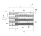
- FIG. 1 is a schematic sectional perspective view of an exhaust gas purifying catalyst according to an embodiment of the present invention.
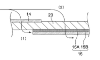
- FIG. 2 is a diagram showing a cross section along the axial direction of the base material for a portion surrounded by a square in FIG.
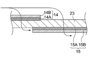
- FIG. 3 is an enlarged view of a portion surrounded by a square in FIG.
- FIG. 4 is a partially enlarged view of a cross section of an exhaust gas purifying catalyst according to another embodiment.
- FIG. 5 is a partially enlarged view of a cross section of an exhaust gas purifying catalyst according to still another embodiment.
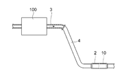
- FIG. 6 is a diagram schematically showing an exhaust gas purification processing system according to one embodiment of the present invention.
- the exhaust gas purifying catalyst 10 is provided in an exhaust passage of an internal combustion engine such as a gasoline engine, particularly a GDI engine of a vehicle.
- the exhaust gas purifying catalyst 10 is used, for example, as a GPF.
- the exhaust gas purifying catalyst 10 has a substrate 11 having a so-called wall flow structure.
- the substrate 11 various materials can be used.
- a substrate formed of ceramics such as cordierite and silicon carbide (SiC) can be suitably used.
- the substrate usually has a columnar outer shape as shown in FIG. 1, and is arranged in the exhaust path of the internal combustion engine such that the axial direction of the columnar outer shape substantially matches the exhaust gas flow direction X.
- FIG. 1 illustrates a substrate having a cylindrical outer shape.
- the outer shape of the entire substrate may be elliptic or polygonal instead of cylindrical.
- the base material 11 extends along the exhaust gas flow direction X, and has an inflow-side cell 21 formed of a space in which the inflow side in the flow direction X is open and the outflow side is closed. It has an outflow side cell 22 extending along X and having a space in which the inflow side in the flow direction X is closed and the outflow side is open.
- the inflow-side cell 21 and the outflow-side cell 22 have a bottomed hole shape.
- the inflow-side cell 21 has an exhaust-gas outflow-side end located at the downstream-side end R2 in the exhaust-gas flow direction X closed with a sealing portion 24, and an exhaust-gas-inflow-side end located at the upstream-side end R1 has an opening. are doing.
- the outflow side cell 22 has an exhaust gas inflow end located at the upstream end R1 closed by the sealing portion 25, and an exhaust gas outflow end located at the downstream end R2 is open.
- the inflow-side cell 21 and the outflow-side cell 22 allow gas, liquid, or the like to flow from an open end (hereinafter, also referred to as an “opening”). Distribution is blocked.
- the inflow-side cell 21 and the outflow-side cell 22 are bottomed hole-shaped spaces extending along the axial direction of the base material 11.
- the cross-sectional shape of the inflow-side cell 21 and the outflow-side cell 22 in a cross section orthogonal to the axial direction of the base material 11 is square, parallelogram, rectangle, trapezoidal rectangle, triangle, hexagon, octagonal polygon, etc.
- Various geometric shapes such as a circle and an ellipse may be used.
- the oxidizing catalyst layer is a catalyst layer mainly containing an oxidation catalyst among the catalytically active components.
- the oxidation catalyst has the property that the action as a catalyst for oxidizing hydrocarbons (HC) and carbon monoxide (CO) is stronger than the action as a catalyst for reducing NO x (nitrogen oxide). It is a catalyst shown.
- the oxidation catalyst include one or two selected from palladium (Pd) and platinum (Pt).
- the reducing catalyst layer is a catalyst layer mainly containing a reducing catalyst among the catalytically active components.
- one of the first catalyst unit 14 and the second catalyst unit 15 has at least one oxidizing catalyst layer and at least one reducing catalyst layer.
- the other has at least one of the oxidizing catalyst layer and the at least one reducing catalyst layer. That is, in the exhaust gas purifying catalyst 10 of the present embodiment, one of the first catalyst unit 14 and the second catalyst unit 15 includes both the oxidizing catalyst layer and the reducing catalyst layer, and the other includes: At least one of the oxidizing catalyst layer and the reducing catalyst layer is included.
- the exhaust gas-purifying catalyst 10 can be configured so that the exhaust gas can come into contact with three or more oxidizing catalyst layers and reducing catalyst layers in total.
- the present inventor has proposed that the contact probability between the exhaust gas and the oxidizing catalyst layer or the reducing catalyst layer is increased to thereby improve the oxidizing catalyst layer and / or the reducing property.
- the contact probability between the exhaust gas and the oxidizing catalyst layer or the reducing catalyst layer is increased to thereby improve the oxidizing catalyst layer and / or the reducing property.
- Examples of the intermediate layer include a layer mainly containing metal oxide particles described below without containing a catalytically active component.
- a predetermined catalyst layer is formed on the partition wall 23
- the catalyst layer is formed on the surface of the partition wall 23 and outside the partition wall 23 on the surface side of the partition wall 23 Including the case where it is formed in.
- the catalyst layer B is laminated on the catalyst layer A
- the catalyst layer B is formed on the surface of the catalyst layer A
- the catalyst layer B is formed outside the catalyst layer A on the surface side of the catalyst layer A. Including the case.
- the layer located on the partition wall 23 side is formed on the “lower layer”, and on the opposite side to the “lower layer” from the partition wall 23.
- the layer is also called “upper layer”.
- the oxidizing catalyst layer or the reducing catalyst layer provided so as to be in direct contact with the partition wall 23 may be present inside the partition wall 23 depending on the particle size of the particles constituting the oxidizing catalyst layer or the reducing catalyst layer, or may be provided on the surface of the partition wall 23. May be present.
- Whether or not the catalyst layer is in direct contact with the partition wall 23 is determined by cutting the catalyst 10 at a cross section orthogonal to the exhaust gas flow direction and scanning the cross section that appears by a scanning electron microscope (for example, “JEM-ARM200F” manufactured by JEOL Ltd.).
- a scanning electron microscope for example, “JEM-ARM200F” manufactured by JEOL Ltd.
- EDS energy dispersive X-ray spectrometry
- the distribution of elements for example, Si, Mg, etc.
- EPMA electron beam micro analyzer
- one catalyst layer (also referred to as a single layer) has a uniform composition.
- One catalyst layer may have a plurality of portions each containing a different catalytically active component in the thickness direction as long as the tendency of whether the oxidizing property or the reducing property is strong is the same.
- one of the first catalyst unit 14 and the second catalyst unit 15 has a laminate of an oxidizing catalyst layer and a reducing catalyst layer
- the other may be a single layer of the oxidizing catalyst layer
- the catalyst layer may be a single layer, or may be a laminate of an oxidizing catalyst layer and a reducing catalyst layer.
- the number of layers of the layer structure in the first catalyst unit 14 and the second catalyst unit 15 is determined by analyzing the distribution of the reduction catalyst component and the oxidation catalyst component by the line analysis of Pd, Pt, Rh, and the like using EDS. Can be identified.
- one of the first catalyst unit 14 and the second catalyst unit 15 is formed of a single layer of the reducing catalyst layer or a single layer of the oxidizing catalyst layer, and the other is formed of the oxidizing catalyst layer and the reducing catalyst layer. And a laminate of two or more layers. Such an example is shown in FIGS.
- the first catalyst portion 14 is composed of a single layer of a reducing catalyst layer or a single layer of an oxidizing catalyst layer, and the other is a laminate of two or more layers of an oxidizing catalyst layer and a reducing catalyst layer.
- Both the exhaust gas (1) that has passed through the first catalyst unit 14 and the gas (2) that has passed through the partition wall 23 in the X direction downstream of the first catalyst unit 14 are the second catalyst unit which is a laminate of two or more layers. 15 can be contacted. Therefore, with this configuration, the contact probability of the exhaust gas with both the oxidizing catalyst layer and the reducing catalyst layer can be increased. Also in the configuration of FIG.
- the total number of the reducing catalyst layer and the oxidizing catalyst layer of the first catalyst unit 14 and the total number of the reducing catalyst layer and the oxidizing catalyst layer of the second catalyst unit 15 are different, particularly, It is preferable that the total number of layers of the second catalyst unit 15 is larger than the total number of layers of the one catalyst unit 14. This is because it is easier to improve the exhaust gas purification performance with a limited amount of the catalytically active component, and it is also easier to suppress the increase in pressure loss. There is also an advantage of suppressing a rise in pressure loss after PM or ash is deposited.
- Another preferred embodiment of the present invention includes a total number of reducing catalyst layers and oxidizing catalyst layers included in the first catalyst unit 14 and a total number of reducing catalyst layers and oxidizing catalyst layers included in the second catalyst unit 15.
- Each of the numbers is two or more.
- FIG. 5 since the oxidizing catalyst layer and the reducing catalyst layer exist in both the first catalyst unit 14 and the second catalyst unit 15, both the oxidizing catalyst layer and the reducing catalyst layer , both the oxidizing catalyst layer and the reducing catalyst layer , The contact probability of the exhaust gas increases, and the purification performance of each gas type of NO x , HC, and CO can be more easily improved. In addition, it is easy to improve the PM collection rate.
- the following embodiments (A) and (A) are preferable.
- the exhaust gas contacts the catalyst layer in the order of the reducing catalyst layer ⁇ the oxidizing catalyst layer ⁇ the reducing catalyst layer.
- the supply of the reducing substance to the reducing catalyst layer is promoted, and the amount of the reducing substance to be purified by the oxidation reaction is reduced, so that the oxidation-reduction of the exhaust gas proceeds smoothly.
- the first catalyst section 14 has an oxidizing catalyst layer formed on the partition wall 23, and a reducing catalyst layer formed on the surface of the oxidizing catalyst layer opposite to the partition wall 23, The two catalyst parts have a reducing catalyst layer formed on the partition wall 23.
- the first catalyst section 14 has a reducing catalyst layer formed on the partition wall 23, and the second catalyst section 15 has an oxidizing catalyst layer formed on the partition wall 23 and the oxidizing catalyst layer in the oxidizing catalyst layer. It has a partition 23 and a reducing catalyst layer formed on the surface on the opposite side.
- the oxidizing catalyst layer or the reducing catalyst layer formed on the partition wall 23 may be formed on the partition wall 23 so as to be in direct contact with the partition wall 23, or may be formed on the partition wall 23 as an intermediate layer. May be formed, but it is preferably formed so as to be in direct contact with the partition wall 23.
- an oxidizing catalyst layer containing Pd directly in contact with the partition wall 23 and a reducing catalyst layer containing Rh in direct contact with the partition wall 23 are arranged with the partition wall 23 interposed therebetween, as in the form of A or B below. Is preferable for a well-balanced oxidation-reduction reaction.
- the first catalyst unit 14 has a reducing catalyst layer that is in direct contact with the partition wall 23 and contains Rh
- the second catalyst unit 15 has an oxidizing catalyst layer that is in direct contact with the partition wall 23 and contains Pd.
- B The first catalyst portion 14 has an oxidizing catalyst layer directly in contact with the partition wall 23 and contains Pd
- the second catalyst portion 15 has a reducing catalyst layer in direct contact with the partition wall 23 and contains Rh.
- the configuration of A or B is preferable in that an efficient purification reaction can be generated in the exhaust gas flow direction of the catalyst 10.
- the length L1 (see FIG. 2) of the first catalyst portion 14 in the exhaust gas flow direction is 10% or more of the length L (see FIG. 2) of the base material in the same direction.
- the length L2 (see FIG. 2) in the exhaust gas flow direction is preferably 30% or more of the length L of the base material in the same direction.
- L1 is 80% or less of L and L2 is 90% or less of L from the viewpoint that the amount of the catalytically active component and the like can be reduced. From these points, it is more preferable that L1 is 30 to 60% of L and L2 is 50 to 80% of L.
- the length of the first catalyst part 14 and the second catalyst part 15 can be measured by the following method. That is, the exhaust gas purifying catalyst 10 is cut along a section including the central axis along the axial direction of the base material 11, the central axis portion of the section is visually observed, and the boundary between the first catalyst portion 14 and the second catalyst It is preferable to specify the boundaries of the parts 15 and measure the lengths of the first catalyst part 14 and the second catalyst part 15, respectively. At this time, for example, the length of the first catalyst unit 14 and the second catalyst unit 15 is measured at arbitrary 10 locations of the exhaust gas purifying catalyst 10 and the average value is calculated by using the average value of the first catalyst unit 14 and the second catalyst unit 15. It is preferable to obtain the length.
- the first catalyst portion 14 is preferably formed to extend downstream from the upstream end portion R1 in the X direction of the base material 11 in terms of compatibility between manufacturability of the catalyst portion and exhaust gas purification performance.
- the second catalyst portion 15 is preferably formed to extend upstream from the downstream end R2 in the X direction of the substrate 11.
- the upper limit of the content of the catalytically active component contained in the first catalyst portion 14 and the second catalyst portion 15 is preferably 10 g / L or less per 1 L of the base material volume, and in some cases, 5 g / L or less, and more preferably 3 g / L or less. It is also possible to use
- the volume of the base material here is an apparent volume including not only the base material part but also the first catalyst part 14 and the second catalyst part 15, the holes in the partition walls 23, and the spaces in the cells 21 and 22.
- the content of Rh contained in the reducing catalyst layer of the first catalyst section 14 is preferably about 0.01 g / L or more and 1 g / L or less, preferably 0.05 g / L or more and 0.5 g / L / L of the base material. L or less is more preferable. Further, the total amount of Pd and Pt contained in the oxidizing catalyst layer of the first catalyst portion 14 is preferably about 0.1 g / L to 5 g / L, more preferably 0.5 g / L to 3 g per 1 L of the base material volume. / L or less is more preferable. The same applies to the content of Rh contained in the reducing catalyst layer of the second catalyst unit 15 and the total amount of Pd and Pt contained in the oxidizing catalyst layer of the second catalyst unit 15.
- the mass ratio of the catalytically active component between the plurality of oxidizing catalyst layers is preferably from 1: 0.3 to 1, more preferably from 1: 0.5 to 1. preferable. This mass ratio is the ratio of the amount of the catalytically active component in the layer having the least catalytically active component to the amount of the catalytically active component in the layer containing the most catalytically active component.
- the mass ratio of the catalytically active component between the plurality of reducing catalyst layers is the same as in the case of the oxidizing catalyst layer.
- the amount of the catalytically active component can be measured, for example, by measuring the amount of a noble metal in a solution obtained by completely dissolving the catalyst layer by ICP-AES.
- the amount of the noble metal in the solution obtained by completely dissolving each catalyst layer and the base material indicates the amount of the noble metal in the solution obtained by completely dissolving only the base material.
- each of the first catalyst unit 14 and the second catalyst unit 15 further contains a catalyst-carrying component that supports a catalytically active component, from the viewpoint of efficiently exhibiting exhaust gas purification performance by the catalytically active component.
- the catalyst-carrying component here include metal oxide particles.
- Specific examples of the metal oxide constituting the metal oxide particles include an inorganic oxide that is an oxygen storage component (also referred to as OSC material, OSC is an abbreviation for oxygen storage capacity) and an inorganic oxide other than the oxygen storage component. Is mentioned.
- the term “metal oxide particles” includes not only individual particles but also particles obtained by bonding metal oxide particles by firing to form a sintered body.
- the state in which the metal oxide particles “support” the catalytically active component means that the catalytically active component is physically or chemically adsorbed or retained on the outer surface or the inner surface of the pores of the metal oxide particle.
- the fact that the metal oxide particles carry the catalytically active component means that the metal oxide component and the catalytically active component are determined by, for example, element mapping obtained by analyzing a cross section of the exhaust gas purifying catalyst 10 by EDS. By confirming that the components are present in the same region, it can be determined that the metal oxide particles "carry" the catalytically active component.
- the inorganic oxide serving as the oxygen storage component may be any metal oxide having a polyvalent state and having the ability to store oxygen.
- CeO 2 or a CZ material ceria containing Ce and Zr
- oxides of rare earth elements other than Ce are preferably used from the viewpoint of thermal stability and the like.
- CeO 2 -ZrO 2 is a solid solution of CeO 2 and ZrO 2 .
- the solid solution of CeO 2 and ZrO 2 can be confirmed by using an X-ray diffractometer (XRD) based on whether or not a single phase derived from CeO 2 -ZrO 2 is formed.
- CeO 2 —ZrO 2 may contain a solid solution of an oxide of a rare earth element other than Ce.
- the preferred amount of CeO 2 in the first catalyst part 14 and the second catalyst part 15 is 5 to 40% by mass.
- the preferred amount of ZrO 2 in the first catalyst part 14 and the second catalyst part 15 is 10 to 80% by mass.
- the preferable amounts of CeO 2 and ZrO 2 referred to here include the amounts of CeO 2 and ZrO 2 which are solid solutions, respectively, the CeO 2 equivalent amount of Ce constituting the ceria-zirconia composite oxide, and the amount of the composite oxide.
- the ZrO 2 conversion amount of Zr constituting the above is included.
- the amounts of CeO 2 and ZrO 2 can be measured, for example, by measuring the amounts of Ce and Zr in a solution obtained by completely dissolving the catalyst layer by ICP-AES and converting them to oxides.
- the amount of Ce and Zr in the solution obtained by completely dissolving each catalyst layer and the base material can be obtained by completely dissolving only the base material. It can be measured by subtracting the amounts of Ce and Zr in the solution.
- Examples of inorganic oxides other than the oxygen storage component that can be included in the first catalyst section 14 include metal oxides other than the oxygen storage component, such as alumina, silica, silica-alumina, titania, and aluminosilicates. Particularly, alumina is preferably used from the viewpoint of excellent heat resistance.
- the content of the inorganic oxide other than the oxygen storage component in the first catalyst section 14 and the second catalyst section 15 is preferably 4 to 50% by mass.
- the amount of alumina can be measured, for example, by measuring the amount of aluminum in a solution obtained by completely dissolving the catalyst layer by ICP-AES and converting it to oxides.
- the amount of Al in the solution obtained by completely dissolving each catalyst layer and the base material indicates the amount of Al in the solution obtained by completely dissolving only the base material. Can be measured by subtracting the amount of Al.
- the cross section of the partition wall provided with the first catalyst portion 14 is observed by the above-mentioned scanning electron microscope and analyzed by EDS, and the element (for example, Si, Mg or the like) existing only in the base material and the catalyst layer are present only.
- the first catalyst part 14 is mainly present on the surface of the partition wall 23 by line analysis of the boundary with the element (for example, Ce, Zr, or the like) to be analyzed, or by a method of analyzing with an electron beam microanalyzer (EPMA). You can confirm that.
- the second catalyst portion 15 exist mainly on the surface of the partition wall 23, not inside the partition wall 23.
- FIGS. 3 to 5 schematically show a state in which the first catalyst portion 14 is mainly present on the surface of the partition wall 23 and the second catalyst portion 15 is mainly present on the surface of the partition wall 23.
- the first catalyst portion 14 exist mainly on the surface of the partition wall 23, not inside the partition wall 23, for example, as metal oxide particles for supporting the catalyst constituting the first catalyst portion 14 and the second catalyst portion 15, A material having a particle diameter that is difficult to pass through the pores of the partition wall 23 may be used. Also, by using an organic pore-forming material having a larger particle size than the pores of the partition walls 23 when forming the catalyst layer, the amount of the catalyst layer present on the surface of the partition walls 23 can be easily increased with respect to the amount present inside the partition walls 23. Become.
- a preferred method for producing the exhaust gas purifying catalyst of the present invention includes the following steps (1) to (3).
- the following method may be appropriately changed for other modes. Any one of the step (1) and the steps (2) and (3) may be performed first.
- Rh is used as one catalytically active component
- Pd or Pt is used as the other catalytically active component.
- the slurry for the first catalyst portion 14 containing the catalytically active component and the metal oxide particles is applied to at least the surface on the upstream side in the X direction of the partition wall 23 on the inflow-side cell 21, and then dried or fired. Process.
- the slurry for the lower layer for the second catalyst portion 15 containing the catalytically active component and the metal oxide particles is applied to at least the surface on the downstream side in the X direction of the partition wall 23 on the outflow side cell 22 side and dried or The step of firing.
- the slurry for the upper layer for the second catalyst portion 15 containing the catalytically active component and the metal oxide particles is applied to the partition wall 23 on the outflow side cell 22 side for the second catalyst portion 15.
- the metal oxide particles include the above-described oxygen storage component or inorganic oxide particles other than the oxygen storage component as the components of the first catalyst unit 14 and the second catalyst unit 15.
- the catalytically active component in each of the above steps is mixed with metal oxide particles in the form of a water-soluble salt such as nitrate to obtain a slurry for the first catalyst portion 14 and a slurry for the second catalyst portion 15, respectively. After being applied to the material 11, drying or baking may be performed.
- the catalytically active component may be supported on metal oxide particles in advance, and the supported metal oxide particles may be used as a slurry.
- Each of the above-mentioned slurries may contain a binder for the purpose of adhering the metal oxide particles carrying the catalytically active component to the substrate.
- the binder include alumina sol, zirconia sol, titania sol, silica sol and the like.
- Each of the above slurries may contain a pore former.
- the pore-forming material for example, cross-linked poly (methyl (meth) acrylate) particles, cross-linked poly (butyl meth) acrylate particles, cross-linked polystyrene particles, cross-linked polyacrylate particles, and the like can be used.
- a method of immersing the upstream or downstream of the substrate 11 in the exhaust gas flow direction in the slurry may be used.
- the slurry may be sucked from the opposite side of the substrate at the same time as the immersion.
- the slurry can be applied to a desired position.
- the drying temperature of the slurry is preferably from 40 to 120 ° C.
- the firing temperature is preferably from 350 to 550 ° C.
- the mass of the first catalyst unit 14 may be controlled according to the amount of the catalytically active component, but the mass after drying forms the first catalyst unit 14.
- the amount is preferably 10 g or more, more preferably 20 g or more, per 1 L of the volume of the base material of the portion.
- the mass of the first catalyst portion 14 is preferably 80 g or less per 1 L of the base material in terms of reduction in pressure loss and improvement in exhaust gas purification performance during high-speed operation. , 60 g or less.
- the mass of the second catalyst portion 15 may be controlled according to the amount of the catalytically active component, but is preferably 20 g or more, more preferably 30 g or more, per 1 L of the volume of the substrate in terms of mass after drying. preferable. In order to reduce the pressure loss, the mass of the second catalyst portion 15 is preferably 80 g or less, more preferably 60 g or less, per 1 L of the volume of the base material in the portion where the second catalyst portion 15 is formed. More preferably, there is.
- the mass ratio between the layer having the largest mass and the layer having the smallest mass is, for example, the former.
- the latter is preferably from 1: 0.2 to 1, more preferably from 1: 0.5 to 1, from the viewpoint of further improving exhaust gas purification performance.
- the exhaust gas purifying catalyst 10 thus manufactured can be used for various applications as an exhaust gas purifying catalyst for an internal combustion engine using a fossil fuel as a power source, such as a gasoline engine, utilizing its exhaust gas purifying performance. Further, according to the present embodiment, an exhaust gas purifying method using such an exhaust gas purifying catalyst 10 can also be provided. For example, by providing the exhaust gas purifying catalyst 10 in an exhaust path of an internal combustion engine such as a gasoline engine, particularly a GDI engine of a vehicle, and using it as a GPF or the like, it becomes possible to satisfactorily purify exhaust gas from a gasoline engine. .
- FIG. 6 shows an example of an exhaust gas purification system using the exhaust gas purification catalyst 10 of the present invention.
- the exhaust gas purifying catalyst 10 is provided in an exhaust system of an internal combustion engine.
- FIG. 6 is a diagram schematically showing the internal combustion engine 100 and the exhaust gas purifying catalyst 10 provided in the exhaust system of the internal combustion engine 100.
- the exhaust gas purifying catalyst 10 is provided in an exhaust system of the internal combustion engine 100.
- the exhaust gas purification processing system 1 has an exhaust gas purification catalyst 2 different from the present embodiment, in addition to the exhaust gas purification catalyst 10 according to the present embodiment.
- the exhaust gas purifying catalyst 10 is located downstream of the other exhaust gas purifying catalyst 2 in the exhaust gas flow direction, and is provided adjacent to the other exhaust gas purifying catalyst 2.
- the exhaust gas purifying catalyst 2 is configured to purify ternary components (NO x , HC, CO) contained in the exhaust gas.
- the type of the exhaust gas purifying catalyst 2 is not particularly limited, and may be, for example, a catalyst supporting a noble metal such as platinum (Pt), palladium (Pd), or rhodium (Rd).
- the exhaust gas purifying catalyst 2 As the exhaust gas purifying catalyst 2, a catalyst having no wall flow structure can be used.
- the exhaust gas purifying catalyst 10 has a PM collecting performance and acts as a GPF. According to the above configuration, the excellent exhaust gas purifying performance of the exhaust gas purifying catalyst 10 can effectively purify harmful components in the exhaust gas without increasing the amount of the catalytically active component.
- the particle diameter of the metal oxide particles and the particle diameter of the pore former used in the first slurry were adjusted for the reducing catalyst layer that is in direct contact with the partition walls 23.
- the positions of both ends in the X direction of the stacked oxidizing catalyst layer and the reducing catalyst layer are almost the same. (The lengths of the stacked oxidizing catalyst layer and reducing catalyst layer were almost the same.)
- the mixture 10% by mass of a pore former (crosslinked poly (methyl methacrylate) particles) based on the solid content of the mixture, and 3% by mass of alumina sol based on the solids of the mixture And a zirconia sol of 5% by mass based on the solid content of the mixed solution, and water as a liquid medium, to prepare a first slurry.
- a pore former crosslinked poly (methyl methacrylate) particles
- CeO 2 -ZrO 2 solid solution powder (containing 40% by mass of CeO 2 , 50% by mass of ZrO 2 , and 10% by mass of an oxide of a rare earth element other than Ce in a CeO 2 -ZrO 2 solid solution) and alumina powder in a mass ratio of 3: 1 and impregnated in an aqueous solution of palladium nitrate.
- the mixed solution 25% by mass of a pore former (crosslinked poly (meth) methacrylate particles) based on the solid content of the mixed solution, and 3% by mass of an alumina sol based on the solid content of the mixed solution And 3% by mass of a zirconia sol based on the solid content of the mixed solution, and water as a liquid medium to prepare a second slurry.
- a pore former crosslinked poly (meth) methacrylate particles
- the substrate 11 has the structure shown in FIG. 1, and has 300 cells / inch 2 on the surface orthogonal to the axial direction and has cells extending in the axial direction defined by partition walls having a thickness of 200 ⁇ m and having a volume of 1 A substrate 11 having a capacity of 0.4 L was used.
- the area of the opening of one inflow-side cell 21 on the inflow-side end face was almost the same as the area of the opening of one outflow-side cell 22 on the outflow-side end face.
- the substrate 11 was fired at 450 ° C. for one hour.
- the exhaust gas purifying catalyst 10 of Example 1 in which the first catalyst portion 14 and the second catalyst portion 15 were formed on the base material 11 was obtained.
- the obtained first catalyst portion 14 is composed of a single layer of the reducing catalyst layer.
- the second catalyst section 15 is formed of a laminate in which an outer layer 15B as a reducing catalyst layer is laminated on an outer surface of a lower layer 15A as an oxidizing catalyst layer.
- the first catalyst portion 14 of the exhaust gas purifying catalyst 10 flows downstream from the upstream end R1 in the exhaust gas flow direction X to 45% of the total length L. It was formed on the surface of the partition wall 23 on the side cell 21 side, and the mass of the first catalyst portion 14 with respect to the volume of the base material in the portion where the first catalyst portion 14 was formed was 55 g / L in terms of mass after drying. .
- the first catalyst unit 14 is described as a “lower layer” of the “first catalyst unit”, and the mass of the first catalyst unit 14 is described as “WC amount” (wash coat amount).
- the lower layer 15A and the upper layer 15B of the second catalyst portion 15 of the exhaust gas purifying catalyst 10 are arranged on the outflow side cell 22 side from the downstream end R2 in the exhaust gas flow direction X to 70% of the total length L on the upstream side. 23 was formed on the surface. After drying, the mass of the portion where the second catalyst portion 15 was formed was 33 g / L for the lower layer 15A and 17 g / L for the upper layer 15B after drying.
- the lower layer 15A is described as the “lower layer” of the “second catalyst portion”
- the upper layer 15B is described as the “upper layer” of the “second catalyst portion”
- the respective masses are described as “WC amount” (wash coat amount). As described.
- Example 2 [3. Formation of Second Catalyst Unit Before Firing]], the order of application of the first slurry and the second slurry was changed. Otherwise in the same manner as in Example 1, an exhaust gas purifying catalyst 10 of Example 2 was obtained.
- Example 4 In the first embodiment, [2. Formation of First Catalyst Unit Before Firing] was changed to the same process as in Example 3. Except that point, the exhaust gas-purifying catalyst 10 of Example 4 was obtained in the same manner as in Example 1.
- the downstream end of the base material 11 on which the first catalyst portion before firing was formed in the exhaust gas flow direction was immersed in the obtained mixed slurry, sucked from the upstream side, and then dried at 70 ° C. for 10 minutes to form a lower layer. did.
- the mass of the lower layer was the same as the sum of the lower layer 15A and the upper layer 15B of Example 1. No upper layer was formed. Except for these, in the same manner as in Example 1, an exhaust gas purifying catalyst 10 of Comparative Example 1 was obtained.
- Example 2 [3. Formation of Second Catalyst Portion Before Firing], the upper layer was not formed. The mass of the lower layer was the same as the sum of the lower layer 15A and the upper layer 15B of Example 1. Except for this, the exhaust gas-purifying catalyst of Comparative Example 2 was obtained in the same manner as in Example 1.
- the vehicle using the exhaust gas purifying catalyst was operated in accordance with the operating conditions of the International Harmonized Exhaust Gas Test Mode (WLTC). From the start of operation, during low-speed operation from 589 seconds to 589 seconds, during medium-speed operation from 589 seconds to 1022 seconds, during high-speed operation, from 1022 seconds to 1,477 seconds, and over 1,477 to 1,800 seconds from operation.
- the number of PM particles (PN cat ) in the exhaust gas passing through the exhaust gas purifying catalyst during each of the high-speed operations was measured. Further, the number of PM particles (PN all ) directly discharged from the engine was measured, and the PM collection rate was determined by the following equation. Table 1 shows the results.
- PM collection rate (%) 100 ⁇ (PN cat / PN all ) ⁇ 100 (Conditions for measuring PM collection rate) ⁇ Evaluation vehicle: 1.5L direct injection turbo engine ⁇ Gasoline: Fuel for certification test ⁇ PM measurement device: HORIBA, Ltd.
Landscapes
- Chemical & Material Sciences (AREA)
- Engineering & Computer Science (AREA)
- Chemical Kinetics & Catalysis (AREA)
- Combustion & Propulsion (AREA)
- Health & Medical Sciences (AREA)
- Mechanical Engineering (AREA)
- General Engineering & Computer Science (AREA)
- Toxicology (AREA)
- Materials Engineering (AREA)
- Organic Chemistry (AREA)
- Ceramic Engineering (AREA)
- Environmental & Geological Engineering (AREA)
- Analytical Chemistry (AREA)
- General Chemical & Material Sciences (AREA)
- Oil, Petroleum & Natural Gas (AREA)
- Biomedical Technology (AREA)
- Exhaust Gas Treatment By Means Of Catalyst (AREA)
- Catalysts (AREA)
- Exhaust Gas After Treatment (AREA)
- Processes For Solid Components From Exhaust (AREA)
Abstract
本発明の排ガス浄化用触媒は、基材が、流入側セルと、流出側セルと、それらを隔てる多孔質の隔壁とを有し、触媒部が、隔壁における流入側セルに臨む面のうち、排ガス流通方向の上流側に設けられた第一触媒部と、流出側セルに臨む面のうち、排ガス流通方向の下流側に設けられた第二触媒部とを有し、第一触媒部及び第二触媒部の一方が、少なくとも1層の酸化性触媒層及び少なくとも1層の還元性触媒層を有し、他方が、少なくとも1層の酸化性触媒層及び/又は少なくとも1層の還元性触媒層を有する。
Description
本発明は、排ガス浄化用触媒に関する。
ガソリンエンジンからなる内燃機関に関しては年々厳しくなる燃費基準に対応するために、直噴エンジン(Gasoline Direct Injection engine、以下GDIともいう)の採用が広がっている。GDIは低燃費及び高出力である一方で、従来のポート噴射式エンジンに比べて排ガス中の粒子状物質(Particulate Matter、以下PMともいう。ススを含む)の排出量が5~10倍以上であることが知られている。このPM排出に関する環境規制に対応するため、GDI等のガソリンエンジン搭載車両においてもディーゼルエンジン搭載車両のようにPM捕集機能を有するフィルタ(Gasoline Particulate Filter、以下GPFともいう)の設置が求められている。
一般に車両における排ガス浄化用触媒の搭載スペースは限られていることから省スペースの観点から、上述のフィルタにPd、Pt、Rh等の貴金属三元触媒成分を担持させて、PMの捕集とともに窒素酸化物(NOx)、一酸化炭素(CO)、炭化水素(HC)等の浄化を行う触媒が近年用いられている。
一般に車両における排ガス浄化用触媒の搭載スペースは限られていることから省スペースの観点から、上述のフィルタにPd、Pt、Rh等の貴金属三元触媒成分を担持させて、PMの捕集とともに窒素酸化物(NOx)、一酸化炭素(CO)、炭化水素(HC)等の浄化を行う触媒が近年用いられている。
例えば特許文献1には、粒子状物質フィルタを有するガソリンエンジン排ガス流の処理システムであって、該粒子状物質フィルタが、粒子状物質フィルタ基材と、該フィルタ基材の排ガス流入口表面上に設けられた流入口層と、該フィルタ基材の排ガス排出口表面上に設けられた排出口層とを含み、該流入口層がRh及び/又はPdを含み、該排出口層がRh及び/又はゼオライトを含む処理システムが記載されている。
しかしながら、貴金属三元触媒成分を担持する従来のフィルタ触媒において、貴金属の使用量を抑制しつつ、更に高い排ガス浄化性能を発揮する技術が求められている。
本発明は従来よりも排ガス浄化性能の高いウォールフロー型排ガス浄化用触媒を提供することを課題としたものである。
本発明者は、ウォールフロー構造を有するフィルタ触媒の構成について鋭意検討した。その結果、基材の流入口側及び排出口側において、酸化性触媒層と還元性触媒層とを特定の条件で配置することにより、従来よりも排ガス浄化性能が高いフィルタ触媒が得られることを知見した。
本発明は前記知見に基づくものであり、
基材と該基材に設けられた触媒部とを備え、
前記基材は、
排ガス流通方向の流入側が開口し且つ流出側が閉塞されている空間からなる流入側セルと、
排ガス流通方向の流入側が閉塞されており且つ流出側が開口している空間からなる流出側セルと、
該流入側セルと該流出側セルとを隔てる多孔質の隔壁とを有し、
前記触媒部は、
前記隔壁における前記流入側セルに臨む面のうち、前記流通方向の上流側の少なくとも一部に設けられた第一触媒部と、
前記隔壁における前記流出側セルに臨む面のうち、前記流通方向の下流側の少なくとも一部に設けられた第二触媒部とを有する排ガス浄化用触媒であって、
前記第一触媒部及び前記第二触媒部の一方が、少なくとも1層の酸化性触媒層及び少なくとも1層の還元性触媒層を有し、
他方が、少なくとも1層の酸化性触媒層及び/又は少なくとも1層の還元性触媒層を有する、排ガス浄化用触媒を提供する。
本発明によれば、従来よりも排ガス浄化性能に優れたフィルタ触媒を提供することができる。
以下本発明を、その好ましい実施形態に基づき説明するが、本発明は下記実施形態に限定されない。
本実施形態の排ガス浄化用触媒10の例を図1ないし図5に示す。これら図面は単に、排ガス浄化用触媒の模式的な例の一つを示すものであり、何ら本発明を限定するものではない。
本実施形態の排ガス浄化用触媒10の例を図1ないし図5に示す。これら図面は単に、排ガス浄化用触媒の模式的な例の一つを示すものであり、何ら本発明を限定するものではない。
排ガス浄化用触媒10は、ガソリンエンジン、特に車両のGDIエンジンなどの内燃機関の排気経路に設けられている。排ガス浄化用触媒10は、例えばGPFとして用いられる。
図1に示すように、排ガス浄化用触媒10は、いわゆるウォールフロー構造を有する基材11を有する。基材11は、種々の材料のものを用いることができ、例えば、コージェライト、炭化ケイ素(SiC)等のセラミックス等から形成されたものを好適に採用することができる。基材は、通常、図1に示すように柱状の外形を有しており、柱状外形の軸方向が排ガス流通方向Xと略一致するように、内燃機関の排気経路に配置されている。図1には、外形が円柱形状である基材が例示されている。もっとも、基材全体の外形については、円柱形に代えて、楕円柱形、多角柱形を採用してもよい。
図1に示すように、基材11は、排ガス流通方向Xに沿って延びるとともに、該流通方向Xの流入側が開口し且つ流出側が閉塞されている空間からなる流入側セル21と、該流通方向Xに沿って延びるとともに、該流通方向Xの流入側が閉塞されており且つ流出側が開口している空間からなる流出側セル22とを有している。
流入側セル21及び流出側セル22は有底孔状をしている。流入側セル21は、排ガス流通方向Xの下流側端部R2に位置する排ガス流出側端部が封止部24で閉塞されており、上流側端部R1に位置する排ガス流入側端部が開口している。流出側セル22は、上流側端部R1に位置する排ガス流入側端部が封止部25で閉塞されており、下流側端部R2に位置する排ガス流出側端部が開口している。流入側セル21及び流出側セル22は、開口端部(以下、「開口部」ともいう)から気体や液体等の流通が可能であり、閉塞した封止部24及び封止部25では排ガスの流通が遮断されている。流入側セル21及び流出側セル22は基材11の軸方向に沿って延びる有底孔状の空間である。基材11の軸方向と直交する断面における流入側セル21及び流出側セル22の断面形状は、正方形、平行四辺形、長方形、台形などの矩形、三角形、六角形、八角形などの多角形、円形、楕円形など種々の幾何学形状であってよい。
流入側セル21と、隣接する流出側セル22との間は、多孔質の隔壁23によって区画されている。隔壁23は、流入側セル21と流出側セル22の側壁を構成している。隔壁23は、排ガス等の気体が通過可能な多孔質構造である。隔壁23の厚みは例えば150μm~400μmが好ましい。ここでいう厚みは、流入側セル21と流出側セル22との間の隔壁23の厚みが一定でない場合は、最も薄い部分の厚みを指す。
基材11は、流入側端部R1におけるひとつの流入側セル21の開口部面積と、流出側端部R2におけるひとつの流出側セル22の開口部の面積とが同じであってもよく、異なっていてもよい。ここでいう開口部の面積とは、基材11の軸方向と直交する平面での面積である。
基材11には、触媒活性成分を有する触媒部が担持されている。図2に示すように、触媒部は、隔壁23の流入側セル21に臨む面のうち、排ガス流通方向X(以下、X方向ともいう)上流側に少なくとも設けられた層状の第一触媒部14と、隔壁23の流出側セル22に臨む面のうち、少なくとも排ガス流通方向Xの下流側に設けられた層状の第二触媒部15を有している。なお、図2~図5のハッチングは後述する酸化性触媒層及び還元性触媒層の位置を限定するものではない。
排ガス浄化用触媒10においては、図2に示すように、基材11の流入側セル21に排ガスが流入する。流入側セル21から流入した排ガスは、多孔質の隔壁23を通過して流出側セル22に到達する。図2においては、流入側セル21に流入した排ガスが隔壁23を通過して流出側セル22に到達する経路を矢印で示している。隔壁23は多孔質構造を有しているので、排ガスがこの隔壁23を通過する間に、PMが隔壁23の表面や隔壁23の内部の細孔内に捕集される。また排ガスが隔壁23の内部及び表面を通過する間に、第一触媒部14及び第二触媒部15の触媒活性成分と接触して、排ガス中の有害成分が浄化される。隔壁23を通過して流出側セル22に到達した排ガスは、流出側セル22の開口から排ガス浄化用触媒10の外部へと排出される。
本実施形態では、第一触媒部14及び第二触媒部15の一方が、少なくとも1層の酸化性触媒層及び少なくとも1層の還元性触媒層を有し、他方が、少なくとも1層の酸化性触媒層及び少なくとも1層の還元性触媒層のうち、何れか一方又は両方を有する。
酸化性触媒層とは、触媒活性成分の中でも酸化触媒を主に含む触媒層である。ここで、酸化触媒は、NOx(窒素酸化物)を還元する触媒としての作用よりも、炭化水素(HC)及び一酸化炭素(CO)を酸化する触媒としての作用の方が強いという性質を示す触媒である。酸化触媒としては、パラジウム(Pd)及び白金(Pt)から選ばれる1種又は2種が挙げられる。一方で、還元性触媒層とは、触媒活性成分の中でも還元触媒を主に含む触媒層である。ここで、還元触媒は、炭化水素(HC)及び一酸化炭素(CO)を酸化する触媒としての作用より、NOx(窒素酸化物)を還元する触媒としての作用が強いという性質を示す触媒である。還元触媒としてはロジウム(Rh)が挙げられる。
酸化性触媒層は、酸化触媒だけでなく、還元触媒や他の触媒活性成分が含まれていてもよいが、酸化触媒の量が、還元触媒及び他の触媒活性成分の合計量よりも多い。ここでの量とは金属元素換算における質量基準である。特に酸化性触媒層に含まれる触媒活性成分の総量のうち、酸化触媒としてのPd及びPtの合計の含有割合が50質量%を上回ることが更に好ましい。ここでいう他の触媒活性成分としては、上述した酸化触媒及び還元触媒以外の成分であり、ルテニウム(Ru)、イリジウム(Ir)、オスミウム(Os)、金(Au)及び銀(Ag)から選ばれる1種又は2種以上が挙げられる。
還元性触媒層は、還元触媒だけでなく、酸化触媒や他の触媒活性成分が含まれていてもよいが、還元触媒の量が、酸化触媒及び他の触媒活性成分の合計量よりも多い。ここでの量とは金属元素換算における質量基準である。特に還元性触媒層に含まれる触媒活性成分の総量のうち、還元触媒としてのRhの含有割合が50質量%を上回ることが更に好ましい。ここでいう他の触媒活性成分としては、Pt及びPdに加えて、前記で挙げたものが挙げられる。
本実施形態では、第一触媒部14及び第二触媒部15の一方が、少なくとも1層の酸化性触媒層及び少なくとも1層の還元性触媒層を有する。そして、他方が、少なくとも1層の酸化性触媒層及び少なくとも1層の還元性触媒層のうち、何れか一方又は両方を有する。すなわち、本実施形態の排ガス浄化用触媒10においては、第一触媒部14及び第二触媒部15のうち一方を、酸化性触媒層及び還元性触媒層を両方とも含むものとし、且つ、他方を、酸化性触媒層及び還元性触媒層の少なくとも一方を含むようにする。これにより、排ガス浄化用触媒10を、排ガスが、合計で3層以上の酸化性触媒層及び還元性触媒層と接触可能な構成とすることができる。この構成により排ガス浄化性能が向上するメカニズムは明確ではないが、本発明者は、排ガスと、酸化性触媒層又は還元性触媒層との接触確率を高めることで酸化性触媒層又は/及び還元性触媒層における酸化還元反応が活発になることが理由の一つではないかと考えている。
本実施形態の排ガス浄化用触媒10において、酸化性触媒層及び還元性触媒層が積層される態様としては、まず隔壁23上に酸化性触媒層が形成され、その酸化性触媒層上に還元性触媒層が積層された構成であってもよいし、あるいは、まず隔壁23上に還元性触媒層が形成され、その還元性触媒層上に酸化性触媒層が積層された構成であってもよい。隔壁23上に形成される酸化性触媒層又は還元性触媒層は、隔壁23上に隔壁23と直接接触するように形成されてもよいし、隔壁23上に中間層を介して形成されてもよい。中間層としては、触媒活性成分を含有せず、主に後述する金属酸化物粒子からなる層などが挙げられる。上述した通り本明細書において隔壁23上に所定の触媒層が形成されていると記載する場合、当該触媒層が隔壁23の表面に形成されている場合及び隔壁23の表面側における隔壁23の外側に形成されている場合を含む。同様に、触媒層A上に触媒層Bが積層されているという場合、触媒層Bが触媒層Aの表面に形成されている場合及び触媒層Aの表面側における触媒層Aの外側に形成されている場合を含む。以下では隔壁23に設けられた酸化性触媒層及び還元性触媒層の積層構造において、隔壁23側に位置する層を「下層」、「下層」に対して隔壁23とは反対側に形成された層を「上層」ともいう。一般に、隔壁23に直接接触するようにして設けられる酸化性触媒層又は還元性触媒層は、それを構成する粒子の粒径等によって隔壁23内部に存在する場合もあれば、隔壁23の表面に存在する場合もある。第一触媒部14における酸化性触媒層と還元性触媒層との積層体において、酸化性触媒層と還元性触媒層との層の境界は、隔壁23の内部に位置するのではなく、隔壁23の流入側セル21に臨む表面の上に位置することが好ましい。同様に、第二触媒部15における酸化性触媒層と還元性触媒層との積層体において、酸化性触媒層と還元性触媒層との層の境界は、隔壁23の内部に位置するのではなく、隔壁23の流出側セル22に臨む表面の上に位置することが好ましい。
触媒層が隔壁23に直接接触しているか否かは、触媒10を排ガス流通方向と直交する断面で切断し、現われた断面を走査型電子顕微鏡(例えば日本電子株式会社製「JEM-ARM200F」)で観察すると共に、エネルギー分散型X線分析(EDS:Energy dispersive X-ray spectrometry)で分析し、基材にのみ存在する元素(例えばSi、Mg等)の分布と触媒層にのみ存在する元素(例えばPd、Pt、Rh等)の分布をそれぞれライン分析する方法によって、確認できる。また上記の断面を電子線マイクロアナライザ(EPMA)により分析する方法によっても確認可能である。前記の切断は、バンドソーなどで基材ごと行う。切断後の触媒を、エポキシ樹脂に埋め込み、前記の断面が表面に現れたサンプルとする。酸化性触媒層と還元性触媒層との積層体において、酸化性触媒層と還元性触媒層との層の境界が、隔壁23の内部ではなく、隔壁23のセル21又は22に臨む表面の上に位置するか否かについても、同様の方法にて確認できる。
下層と上層との境界が隔壁23のセル21又は22に臨む表面の上に位置する構成とするためには、下層の触媒層を構成する触媒担持用金属酸化物粒子として、隔壁の細孔を通りにくい粒径のものを用いたり、下層を形成するスラリーに隔壁の細孔を通りにくい粒径の造孔材を使用すればよい。
酸化性触媒層と還元性触媒層との積層体における酸化性触媒層と還元性触媒層の合計層数の数は2以上である。また、第一触媒部14及び第二触媒部15における酸化性触媒層と還元性触媒層との合計層数は、排ガス浄化用触媒10の製造コストや圧損防止の観点から4以下であることが好ましく、3であることがより好ましい。なお酸化性触媒層同士が還元性触媒層を介さずに積層した構造の層数は、2以上とカウントせず1とカウントする。同様に、還元性触媒層同士が酸化性触媒層を介さずに積層した構造の層数は、2以上とカウントせず1とカウントする。本明細書において、一層(単層ともいう)の触媒層は、均一な組成であることは必要ではない。一層の触媒層は、酸化性又は還元性のいずれが強いかという傾向が同じであれば、厚み方向にそれぞれ異なる触媒活性成分を含む複数の部分を有していてもよい。
第一触媒部14及び第二触媒部15の一方が、酸化性触媒層と還元性触媒層との積層体を有する場合、他方は、酸化性触媒層単層であってもよいし、還元性触媒層単層であってもよいし、酸化性触媒層及び還元性触媒層の積層体であってもよい。
第一触媒部14及び第二触媒部15における層構造の層数は、EDSによる前記のPd、Pt、Rh等)等のライン分析により、還元触媒成分及び酸化触媒成分の分布を分析することで特定できる。
本発明における好ましい一実施形態として、第一触媒部14が有する酸化性触媒層及び還元性触媒層の合計層数と、第二触媒部15が有する酸化性触媒層及び還元性触媒層の合計層数とが異なる形態が挙げられる。ここでいう合計層数は、第一触媒部14又は第二触媒部15が酸化性触媒層のみ又は還元性触媒層のみを有する場合は1層である。
第一触媒部14が有する酸化性触媒層及び還元性触媒層の合計層数と、第二触媒部15が有する酸化性触媒層及び還元性触媒層の合計層数とが異なる場合、層数の少ない触媒層は圧損低減に寄与し,層数の多い触媒層は排ガス浄化性能の向上に寄与するため、圧損低減と浄化性能向上を容易に両立できる構成を採用しやすい。この場合の好ましい構成としては、第一触媒部14及び第二触媒部15の一方が、還元性触媒層単層又は酸化性触媒層単層からなり、他方が酸化性触媒層と還元性触媒層との2層以上の積層体である構成が挙げられる。このような例を図3及び図4に示す。
図3に示す、第一触媒部14が還元性触媒層単層又は酸化性触媒層単層からなり、他方が酸化性触媒層と還元性触媒層との2層以上の積層体である構成では、第一触媒部14を通過した排ガス(1)も、第一触媒部14よりもX方向下流側で隔壁23を通過したガス(2)も、2層以上の積層体である第二触媒部15と接触できる。従ってこの構成では、酸化性触媒層及び還元性触媒層の両方との排ガスの接触確率を高めることができる。図4の構成においても、流入側において酸化性触媒層及び還元性触媒層の両方を配置することで、流入側及び排出側に触媒層を一層ずつしか配さない従来の構成に比して、排ガスと酸化性触媒層又は還元性触媒層との接触確率を高めることができる。
第一触媒部14が有する還元性触媒層及び酸化性触媒層の合計層数と、第二触媒部15が有する還元性触媒層及び酸化性触媒層の合計層数とが異なる場合、特に、第一触媒部14の前記合計層数よりも、第二触媒部15の前記合計層数が多いことが好ましい。限られた触媒活性成分の量で排ガス浄化性能を向上させることが一層容易となり、また圧損上昇抑制も容易であるためである。またPMやアッシュ堆積後の圧損上昇を抑制するメリットもある。
本発明における好ましい別の実施形態は、第一触媒部14が有する還元性触媒層及び酸化性触媒層の合計層数及び第二触媒部15が有する還元性触媒層及び酸化性触媒層の合計層数がいずれも2以上である構成である。このような例を図5に示す。図5に示す実施形態では、第一触媒部14及び第二触媒部15の両方に酸化性触媒層及び還元性触媒層が存在することになるので、酸化性触媒層及び還元性触媒層両方への排ガスの接触確率が高まり、NOx、HC及びCOの各ガス種の浄化性能の向上が一層容易となる。またPM捕集率を向上させやすい。
好ましくは、第一触媒部14及び第二触媒部15の両方にRhを含む還元性触媒層が存在する。この場合X方向において、基材におけるRhを含む還元性触媒層が配される部分の割合が大きくなるため、排ガスとRhを含む還元性触媒層との接触確率が効果的に高まり、NOx浄化性能を大きく向上させることができる。NOx排出規制は近年特に厳しくなっているため、この場合の排ガス浄化用触媒10は産業上の利用可能性が特に高いものとなる。
第一触媒部14及び第二触媒部15の両方に還元性触媒層が存在する構成のうち、好ましいものとしては、以下(ア)又は(イ)の実施形態が挙げられる。下記(ア)又は(イ)の形態であると、排ガスが還元性触媒層→酸化性触媒層→還元性触媒層の順序で触媒層に接触する。これにより、還元性触媒層への還元物質の供給が促進されるとともに、酸化反応で浄化すべき還元物質の量が減少するため排ガスの酸化還元がスムーズに進行する。これらは特にNOx還元効率向上に効果的である。
(ア)第一触媒部14が隔壁23上に形成された酸化性触媒層と、該酸化性触媒層における該隔壁23と反対側の表面に形成された還元性触媒層を有し、前記第二触媒部が、隔壁23上に形成された還元性触媒層を有する。
(イ)第一触媒部14が隔壁23上に形成された還元性触媒層を有し、第二触媒部15が隔壁23上に形成された酸化性触媒層と、該酸化性触媒層における該隔壁23と反対側の表面に形成された還元性触媒層とを有する。
(ア)第一触媒部14が隔壁23上に形成された酸化性触媒層と、該酸化性触媒層における該隔壁23と反対側の表面に形成された還元性触媒層を有し、前記第二触媒部が、隔壁23上に形成された還元性触媒層を有する。
(イ)第一触媒部14が隔壁23上に形成された還元性触媒層を有し、第二触媒部15が隔壁23上に形成された酸化性触媒層と、該酸化性触媒層における該隔壁23と反対側の表面に形成された還元性触媒層とを有する。
特に前記(ア)及び(イ)においては、各酸化性触媒層がPdを含有し、且つ各還元性触媒層がRhを含有していることが、排ガス浄化性能を一層高めることができる点で好ましい。この理由は、Pd、Rhの作用により、PdによるHC及びCO酸化とRhによるNOx還元とを好適なバランスで行うことができるためと考えられる。また、前記(ア)及び(イ)においては、第一触媒部14及び第二触媒部15の両方に還元性触媒層が存在するため、排ガス浄化用触媒10中、X方向の広範囲に還元性触媒層が存在することとなり、NOx浄化を効率的に行うことができ、特に高速運転時のNOx浄化性能に優れている。このため排ガス浄化用触媒10を車両に搭載することで効果的にNOx排出量を低減させることができる。
なお、上述したように、隔壁23上に形成される酸化性触媒層又は還元性触媒層は、隔壁23上に隔壁23と直接接触するように形成されてもよいし、隔壁23上に中間層を介して形成されてもよいが、隔壁23上に直接接触するように形成されていることが好ましい。特に、以下A又はBの形態のように、隔壁23に直接接触するPdを含む酸化性触媒層と、隔壁23に直接接触するRhを含む還元性触媒層とが、隔壁23を挟んで配置されることが、バランスのよい酸化還元反応のために好ましい。
A:第一触媒部14が、隔壁23と直接接触し且つRhを含む還元性触媒層を有し、第二触媒部15が、隔壁23と直接接触し且つPdを含む酸化性触媒層を有する。
B:第一触媒部14が、隔壁23と直接接触し且つPdを含む酸化性触媒層を有し、第二触媒部15が、隔壁23と直接接触し且つRhを含む還元性触媒層を有する。
前記A又はBの構成であると、触媒10の排ガス流通方向に亘り効率の良い浄化反応を生じさせうる点で好ましい。
A:第一触媒部14が、隔壁23と直接接触し且つRhを含む還元性触媒層を有し、第二触媒部15が、隔壁23と直接接触し且つPdを含む酸化性触媒層を有する。
B:第一触媒部14が、隔壁23と直接接触し且つPdを含む酸化性触媒層を有し、第二触媒部15が、隔壁23と直接接触し且つRhを含む還元性触媒層を有する。
前記A又はBの構成であると、触媒10の排ガス流通方向に亘り効率の良い浄化反応を生じさせうる点で好ましい。
排ガス浄化性能を一層向上させるために、第一触媒部14の排ガス流通方向の長さL1(図2参照)が基材の同方向の長さL(図2参照)に対して10%以上であることが好ましい。第二触媒部15に関しては、排ガス流通方向の長さL2(図2参照)が基材の同方向の長さLに対して30%以上であることが好ましい。またL1はLに対して80%以下であり、L2がLに対して90%以下であることが、触媒活性成分等の量を低減できる点で好ましい。これらの点からL1はLに対して30~60%であり、L2がLに対して50~80%であることがより好ましい。
第一触媒部14及び第二触媒部15の長さは以下の方法にて測定することができる。すなわち、排ガス浄化用触媒10を基材11の軸方向に沿って中心軸を含む断面で切断して、断面の中心軸部分を目視で観察し、第一触媒部14の境界と、第二触媒部15の境界とをそれぞれ特定し、第一触媒部14及び第二触媒部15をそれぞれ測長することが好ましい。この際には、例えば排ガス浄化用触媒10の任意の10ヶ所について第一触媒部14及び第二触媒部15を測長し、その平均値を、第一触媒部14及び第二触媒部15の長さとして求めることが好ましい。目視で第一触媒部14、第二触媒部15に係る排ガス流通方向における境界が判断できない場合には、排ガス浄化用触媒における排ガス流通方向に沿う多数(例えば8~16か所)の位置における組成を分析し、各箇所における触媒活性成分の濃度に基づき特定することができる。各箇所における触媒活性成分の濃度は、例えば、蛍光X線分析(XRF)やICP発光分光分析(ICP-AES)により求めることができる。
第一触媒部14は、基材11のX方向の上流側端部R1から下流側に延びて形成されていることが、触媒部の製造容易性と排ガス浄化性能との両立の点で好ましい。同様に、第二触媒部15は、基材11のX方向の下流側端部R2から上流側に延びて形成されていることが好ましい。
排ガス浄化用触媒10の排ガス浄化性能を一層高める点から、第一触媒部14に含まれる触媒活性成分の含有量(酸化触媒、還元触媒、及び他の触媒活性成分の合計量)は、基材の体積1L当たり、概ね0.01g以上が好ましく、0.05g以上がより好ましい。第二触媒部15に含まれる触媒活性成分の含有量(酸化触媒、還元触媒、及び他の触媒活性成分の合計量)は、基材の体積1L当たり、概ね0.01g以上が好ましく、0.05g以上がより好ましい。第一触媒部14及び第二触媒部15に含まれる触媒活性成分の含有量の上限は基材体積1L当たり10g/L以下であることが好ましく、場合により5g/L以下、更に3g/L以下とすることも可能である。ここでいう基材の体積は、基材部分だけでなく第一触媒部14及び第二触媒部15、隔壁23中の空孔、セル21及び22内の空間を含めた見掛けの体積である。
第一触媒部14の還元性触媒層に含まれるRhの含有量は、基材の体積1L当たり、概ね0.01g/L以上1g/L以下が好ましく、0.05g/L以上0.5g/L以下がより好ましい。また第一触媒部14の酸化性触媒層に含まれるPd及びPtの合計量は、基材の体積1L当たり、概ね0.1g/L以上5g/L以下が好ましく、0.5g/L以上3g/L以下がより好ましい。第二触媒部15の還元性触媒層に含まれるRhの含有量、及び第二触媒部15の酸化性触媒層に含まれるPd及びPtの合計量についても同様である。
複数の酸化性触媒層を有する場合、当該複数の酸化性触媒層間の触媒活性成分の質量比は1:0.3~1であることが好ましく、1:0.5~1であることがより好ましい。この質量比は最も多く触媒活性成分を含有する層における触媒活性成分の量に対する、最も触媒活性成分の少ない層における触媒活性成分の量の比である。複数の還元性触媒層を有する場合、当該複数の還元性触媒層間の触媒活性成分の質量比は酸化性触媒層の場合と同様である。
触媒活性成分の量は、例えば、触媒層を全溶解して得られる溶液中の貴金属の量をICP-AESで測定することにより測定できる。なお、基材の隔壁内に触媒層が含まれる場合には、各触媒層及び基材を全溶解して得られる溶液中の貴金属の量から、基材のみを全溶解して得られる溶液中の貴金属の量を差し引くことにより測定できる。
第一触媒部14及び第二触媒部15は、それぞれ、触媒活性成分を担持する触媒担持成分を更に含有することが、触媒活性成分による排ガス浄化性能を効率よく発揮する点で好ましい。ここでいう触媒担持成分としては、金属酸化物粒子が挙げられる。金属酸化物粒子を構成する金属酸化物としては、具体的には、酸素貯蔵成分(OSC材料ともいう、OSCはoxygen storage capacityの略)である無機酸化物や、酸素貯蔵成分以外の無機酸化物が挙げられる。なお、本明細書において金属酸化物粒子という場合、個々の粒子のみならず、焼成により金属酸化物粒子同士が結合して焼結体となったものも含む。
本明細書中、金属酸化物粒子が触媒活性成分を「担持」した状態とは、金属酸化物粒子の外表面又は細孔内表面に触媒活性成分が物理的又は化学的に吸着又は保持されている状態をいう。具体的には、金属酸化物粒子が触媒活性成分を担持していることは、例えば排ガス浄化用触媒10の断面をEDSで分析して得られた元素マッピングにて、金属酸化物成分と触媒活性成分とが同じ領域に存在することを確認することで、金属酸化物粒子が触媒活性成分を「担持」していると判断できる。
酸素貯蔵成分である無機酸化物としては、多価状態を有する金属酸化物であって酸素を貯蔵する能力を有するものであればよく、例えば、CeO2やCZ材(Ce及びZrを含有するセリア-ジルコニア複合酸化物や、CeO2とZrO2との固溶体)、酸化鉄、酸化銅が挙げられる。これらに加えて、Ce以外の希土類元素の酸化物が熱的安定性の観点等から好ましく用いられる。Ce以外の希土類元素の酸化物としては、Sc2O3、Y2O3、La2O3、Pr6O11、Nd2O3、Sm2O3、Eu2O3、Gd2O3、Tb4O7、Dy2O3、Ho2O3、Er2O3、Tm2O3、Yb2O3及びLu2O3が挙げられる。なお、CeO2-ZrO2はCeO2とZrO2との固溶体である。CeO2及びZrO2が固溶体となっていることは、X線回折装置(XRD)を用い、CeO2-ZrO2に由来する単相が形成されているか否かにより確認することができる。CeO2-ZrO2には前記のCe以外の希土類元素の酸化物が固溶していてもよい。特に、耐熱性とOSCとのバランスの観点から、第一触媒部14および第二触媒部15中の好ましいCeO2の量は5~40質量%である。第一触媒部14および第二触媒部15中の好ましいZrO2の量は10~80質量%である。ここでいう好ましいCeO2及びZrO2の量は、固溶体となっているCeO2やZrO2の量をそれぞれ含むほか、セリア-ジルコニア複合酸化物を構成するCeのCeO2換算量及び該複合酸化物を構成するZrのZrO2換算量をそれぞれ含む。
CeO2及びZrO2の量は、例えば、触媒層を全溶解して得られる溶液中のCe及びZrの量をICP-AESで測定し、酸化物換算することにより測定できる。なお、基材の隔壁内に触媒層が含まれる場合には、各触媒層及び基材を全溶解して得られる溶液中のCe及びZrの量から、基材のみを全溶解して得られる溶液中のCe及びZrの量を差し引くことにより測定できる。
第一触媒部14に含まれうる酸素貯蔵成分以外の無機酸化物としては、酸素貯蔵成分以外の金属酸化物が挙げられ、アルミナ、シリカ、シリカ-アルミナ、チタニア、アルミノシリケート類が挙げられる。特にアルミナが耐熱性に優れるという観点で好ましく用いられる。第一触媒部14及び第二触媒部15中における酸素貯蔵成分以外の無機酸化物の含有量は、好ましくは4~50質量%である。
アルミナの量は、例えば、触媒層を全溶解して得られる溶液中のアルミニウムの量をICP-AESで測定し、酸化物換算することにより測定できる。なお、基材の隔壁内に触媒層が含まれる場合には、各触媒層及び基材を全溶解して得られる溶液中のAlの量から、基材のみを全溶解して得られる溶液中のAlの量を差し引くことにより測定できる。
PM捕集能を一層高める点や排ガス浄化性能を一層高める点から、第一触媒部14は、隔壁23の内部ではなく、主に隔壁23の表面に存在することが好ましい。第一触媒部14が主に隔壁23の表面に存在するとは、第一触媒部14が設けられた基材11の断面において、基材11の隔壁23の表面に存在する第一触媒部14の質量が隔壁23の内部に存在する第一触媒部14の質量よりも多いことをいう。例えば第一触媒部14が設けられた隔壁の断面を、上述した走査型電子顕微鏡で観察すると共に、EDS分析し、基材にのみ存在する元素(例えばSi、Mg等)と触媒層にのみ存在する元素(例えばCe、Zr等)との境界をライン分析することや、電子線マイクロアナライザ(EPMA)により分析する方法等によって、第一触媒部14が主に隔壁23の表面に存在していることを確認できる。同様に、第二触媒部15は、隔壁23の内部ではなく、主に隔壁23の表面に存在することが好ましい。図3~図5では、第一触媒部14が主に隔壁23の表面に存在し、第二触媒部15が主に隔壁23の表面に存在する状態を模式的に示している。
第一触媒部14を隔壁23の内部ではなく、主に隔壁23の表面に存在させるためには例えば第一触媒部14及び第二触媒部15を構成する触媒担持用の金属酸化物粒子として、隔壁23の細孔を通り難い粒径のものを用いればよい。また触媒層形成時に隔壁23の細孔よりも粒径が大きな有機造孔材を用いることによっても、隔壁23の表面に存在させる触媒層の量を隔壁23内部に存在する量に対して高めやすくなる。
次いで、以下、本発明の排ガス浄化用触媒の好ましい製造方法について説明する。
例えば図3に示す実施形態の排ガス浄化用触媒10の好適な製造方法は、以下の(1)~(3)の工程を有する。その他の形態についても下記方法を適宜変更すればよい。(1)の工程と(2)及び(3)の工程とはいずれを先に行ってもよい。(2)及び(3)の工程においては、一方の触媒活性成分としてRhを用い、他方の触媒活性成分としてPd又はPtを用いる。
(1)触媒活性成分と、金属酸化物粒子とを含有する第一触媒部14用スラリーを、流入側セル21側の隔壁23における少なくともX方向上流側の表面に塗布した後、乾燥又は焼成する工程。
(2)触媒活性成分と、金属酸化物粒子とを含有する第二触媒部15用の下層用スラリーを、流出側セル22側の隔壁23における少なくともX方向下流側の表面に塗布して乾燥又は焼成させる工程。
(3)(2)の後、触媒活性成分と、金属酸化物粒子とを含有する第二触媒部15用の上層用スラリーを、流出側セル22側の隔壁23における第二触媒部15用の下層用スラリー塗布箇所の少なくとも一部に塗布し、乾燥又は焼成させる工程。
金属酸化物粒子としては、第一触媒部14及び第二触媒部15の構成成分として上述した酸素貯蔵成分又は酸素貯蔵成分以外の無機酸化物の粒子が挙げられる。前記の各工程における触媒活性成分は、硝酸塩などの水溶性塩の状態で金属酸化物粒子と混合してそれぞれ第一触媒部14用スラリー及び第二触媒部15用スラリーを得て、これらを基材11に塗布した後、乾燥又は焼成を行ってもよい。あるいは、触媒活性成分は、予め金属酸化物粒子に担持させ、担持後の金属酸化物粒子をスラリーとしてもよい。触媒活性成分を予め担持する場合は金属酸化物粒子を触媒活性成分の水溶性塩の水溶液に含浸させたのち、350~550℃で焼成する方法が挙げられる。
前記の各スラリーには、基材に触媒活性成分を担持した金属酸化物粒子を密着させる目的で、バインダーを含有させてもよい。バインダーとしては、例えばアルミナゾル、ジルコニアゾル、チタニアゾル、シリカゾル等が挙げられる。前記の各スラリーは、造孔材を含有させてもよい。造孔材としては、例えば架橋ポリ(メタ)アクリル酸メチル粒子、架橋ポリ(メタ)アクリル酸ブチル粒子、架橋ポリスチレン粒子、架橋ポリアクリル酸エステル粒子などを用いることができる。
前記のスラリーを基材11に塗布するためには、当該スラリー中に基材11の排ガス流通方向上流側又は下流側を浸漬させる方法が挙げられる。当該浸漬と同時に基材の反対側からスラリーを吸引してもよい。このような方法により、スラリーを所望の位置に塗布できる。前記の各工程においてスラリーの乾燥温度は、いずれも40~120℃が好ましく、焼成温度は、いずれも350~550℃が好ましい。
更に本実施形態の排ガス浄化用触媒10においては、第一触媒部14の質量は、触媒活性成分の量に応じて制御すればよいが、乾燥後の質量で、第一触媒部14を形成した部分の基材の体積1Lあたり10g以上であることが好ましく、特に20g以上であることがより好ましい。第一触媒部14の質量は、乾燥後の質量で、基材の体積1Lあたり80g以下であることが圧力損失の低減の観点、及び、高速運転時の排ガス浄化性能の向上などの点で好ましく、60g以下であることがより好ましい。第二触媒部15の質量は、触媒活性成分の量に応じて制御すればよいが、乾燥後の質量で、基材の体積1Lあたり20g以上であることが好ましく、30g以上であることがより好ましい。圧力損失の低減のために、第二触媒部15の質量は、乾燥後の質量で、第二触媒部15を形成した部分の基材の体積1Lあたり80g以下であることが好ましく、60g以下であることがより好ましい。
第一触媒部14又は第二触媒部15が酸化性触媒層及び還元性触媒層を合計で2層以上有する場合、最も質量が多い層と、最も質量が少ない層とのの質量比は例えば前者:後者が1:0.2~1、より好ましくは1:0.5~1であることが、排ガス浄化性能がより向上するという観点から好ましい。
このように製造された排ガス浄化用触媒10は、その排ガス浄化性能を活かし、ガソリンエンジンなど化石燃料を動力源とする内燃機関の排ガス浄化用触媒として、種々の用途に用いることができる。また、本実施形態によれば、このような排ガス浄化用触媒10を用いた排ガス浄化方法も提供することができる。例えば、排ガス浄化用触媒10を、ガソリンエンジン、特に車両のGDIエンジンなどの内燃機関の排気経路に設けて、GPF等として用いることで、ガソリンエンジンからの排ガスを良好に浄化することが可能となる。
本発明の排ガス浄化用触媒10を用いる排ガス浄化処理システムの一例を図6に示す。排ガス浄化用触媒10は、内燃機関の排気系に設けられている。図6は、内燃機関100と、該内燃機関100の排気系に設けられた排ガス浄化用触媒10を模式的に示す図である。
本実施形態に係る内燃機関であるエンジンには、酸素と燃料ガスとを含む混合ガスが供給される。内燃機関は、この混合ガスを燃焼させ、燃焼エネルギーを力学的エネルギーに変換する。燃焼された混合ガスは排ガスとなって排気系に排出される。図6に示す構成の内燃機関100は、自動車のガソリンエンジンを主体として構成されている。前記内燃機関100を排気系に連通させる不図示の排気ポートには、エキゾーストマニホールド3が接続されている。エキゾーストマニホールド3は、排ガスが流通する排気管4に接続されている。エキゾーストマニホールド3と排気管4とにより内燃機関100の排ガスの流通経路が形成されている。図中の矢印は排ガス流通方向を示している。排ガス浄化用触媒10は、前記内燃機関100の排気系に設けられている。排ガス浄化処理システム1は、本実施形態に係る排ガス浄化用触媒10に加えて、本実施形態とは別の排ガス浄化用触媒2を有している。排ガス浄化用触媒10は別の排ガス浄化用触媒2の排ガス流通方向下流側に位置しており、当該別の排ガス浄化用触媒2と隣接して設けられている。排ガス浄化用触媒2は排ガス中に含まれる三元成分(NOx、HC、CO)を浄化可能なものとして構成されている。排ガス浄化用触媒2の種類は特に限定されず、例えば、白金(Pt)、パラジウム(Pd)、ロジウム(Rd)等の貴金属が担持された触媒であってもよい。排ガス浄化用触媒2としてはウォールフロー構造を有しないものを用いることができる。一方、排ガス浄化用触媒10は、PM捕集性能を有し、GPFとして作用する。
以上の構成によれば、排ガス浄化用触媒10の優れた排ガス浄化性能により、触媒活性成分の量を増加させずに排ガス中の有害成分を効果的に浄化できる。
以上の構成によれば、排ガス浄化用触媒10の優れた排ガス浄化性能により、触媒活性成分の量を増加させずに排ガス中の有害成分を効果的に浄化できる。
以下、実施例により本発明を更に詳細に説明する。しかしながら本発明の範囲は、かかる実施例に制限されない。下記実施例及び比較例において乾燥及び焼成はすべて大気中で行った。また触媒活性成分の使用量は、各触媒層中の触媒活性成分量が表1に示す量となるように調整した。また、隔壁23と直接接触する酸化性触媒層については、基材11の隔壁23の表面に存在する酸化性触媒層の質量が、隔壁23の内部に存在する酸化性触媒層の質量よりも多くなるように、第2のスラリーに用いる金属酸化物粒子の粒径及び造孔材の粒径を調整した。隔壁23と直接接触する還元性触媒層についても、同様に、第1のスラリーに用いる金属酸化物粒子の粒径及び造孔材の粒径を調整した。
また下記の各実施例において、酸化性触媒層及び還元性触媒層を積層させる場合には、積層された酸化性触媒層及び還元性触媒層のそれぞれのX方向両端部の位置はほぼ同じであった(積層された酸化性触媒層及び還元性触媒層のそれぞれの長さはほぼ同じであった。)。
また下記の各実施例において、酸化性触媒層及び還元性触媒層を積層させる場合には、積層された酸化性触媒層及び還元性触媒層のそれぞれのX方向両端部の位置はほぼ同じであった(積層された酸化性触媒層及び還元性触媒層のそれぞれの長さはほぼ同じであった。)。
<実施例1>
〔1.スラリーの調製〕
(第1のスラリー)
CeO2-ZrO2固溶体粉末(CeO2-ZrO2固溶体中にCeO215質量%、ZrO270質量%、Ce以外の希土類元素の酸化物15質量%を含有)及びアルミナ粉末を用意した。CeO2-ZrO2固溶体粉末とアルミナ粉末とを質量比10:1で混合し、硝酸ロジウム水溶液中に含浸させた。
次いで、この混合液と、該混合液の固形分に対して10質量%の造孔材(架橋ポリ(メタ)アクリル酸メチル粒子)と、該混合液の固形分に対して3質量%のアルミナゾルと、該混合液の固形分に対して5質量%のジルコニアゾルと、液媒として水と、を混合して、第1のスラリーを調製した。
〔1.スラリーの調製〕
(第1のスラリー)
CeO2-ZrO2固溶体粉末(CeO2-ZrO2固溶体中にCeO215質量%、ZrO270質量%、Ce以外の希土類元素の酸化物15質量%を含有)及びアルミナ粉末を用意した。CeO2-ZrO2固溶体粉末とアルミナ粉末とを質量比10:1で混合し、硝酸ロジウム水溶液中に含浸させた。
次いで、この混合液と、該混合液の固形分に対して10質量%の造孔材(架橋ポリ(メタ)アクリル酸メチル粒子)と、該混合液の固形分に対して3質量%のアルミナゾルと、該混合液の固形分に対して5質量%のジルコニアゾルと、液媒として水と、を混合して、第1のスラリーを調製した。
(第2のスラリー)
CeO2-ZrO2固溶体粉末(CeO2-ZrO2固溶体中にCeO240質量%、ZrO250質量%、Ce以外の希土類元素の酸化物10質量%を含有)及びアルミナ粉末を質量比3:1で混合し、硝酸パラジウム水溶液中に含浸させた。
次いで、この混合液と、該混合液の固形分に対して25質量%の造孔材(架橋ポリ(メタ)アクリル酸メチル粒子)と、該混合液の固形分に対して3質量%のアルミナゾルと、該混合液の固形分に対して3質量%のジルコニアゾルと、液媒として水と、を混合して、第2のスラリーを調製した。
CeO2-ZrO2固溶体粉末(CeO2-ZrO2固溶体中にCeO240質量%、ZrO250質量%、Ce以外の希土類元素の酸化物10質量%を含有)及びアルミナ粉末を質量比3:1で混合し、硝酸パラジウム水溶液中に含浸させた。
次いで、この混合液と、該混合液の固形分に対して25質量%の造孔材(架橋ポリ(メタ)アクリル酸メチル粒子)と、該混合液の固形分に対して3質量%のアルミナゾルと、該混合液の固形分に対して3質量%のジルコニアゾルと、液媒として水と、を混合して、第2のスラリーを調製した。
〔2.焼成前の第一触媒部の形成〕
基材11として、図1に示す構造を有し、厚さが200μmの隔壁で区画された軸方向に延びるセルを、軸方向と直交する面において、300セル/inch2有し、体積が1.4Lである基材11を用いた。基材11は、流入側端面におけるひとつの流入側セル21の開口部の面積と、流出側端面におけるひとつの流出側セル22の開口部の面積とが概ね同じであった。
基材11として、図1に示す構造を有し、厚さが200μmの隔壁で区画された軸方向に延びるセルを、軸方向と直交する面において、300セル/inch2有し、体積が1.4Lである基材11を用いた。基材11は、流入側端面におけるひとつの流入側セル21の開口部の面積と、流出側端面におけるひとつの流出側セル22の開口部の面積とが概ね同じであった。
第1のスラリー中に基材11の排ガス流通方向の上流側端部を浸漬し、下流側から吸引した後に70℃で10分乾燥させた。これにより隔壁23における流入側セル21に臨む面に、第1のスラリーの固形分からなる層(焼成前の第一触媒部)を設けた。
〔3.焼成前の第二触媒部の形成〕
乾燥後の基材11の排ガス流通方向の下流側端部を、第2のスラリー中に浸漬し、上流側から吸引した後に70℃で10分乾燥させた。これにより隔壁23における流出側セル22に臨む面に、第2のスラリーの固形分からなる下層を設けた。
続いて第2のスラリー乾燥後の基材11における排ガス流通方向の下流側端部を今度は第1のスラリーに浸漬し、再度上流側から吸引した後に70℃で10分乾燥させた。これにより前記下層と第1のスラリー固形分からなる上層との積層体(焼成前の第二触媒部)を形成した。
乾燥後の基材11の排ガス流通方向の下流側端部を、第2のスラリー中に浸漬し、上流側から吸引した後に70℃で10分乾燥させた。これにより隔壁23における流出側セル22に臨む面に、第2のスラリーの固形分からなる下層を設けた。
続いて第2のスラリー乾燥後の基材11における排ガス流通方向の下流側端部を今度は第1のスラリーに浸漬し、再度上流側から吸引した後に70℃で10分乾燥させた。これにより前記下層と第1のスラリー固形分からなる上層との積層体(焼成前の第二触媒部)を形成した。
〔4.焼成〕
その後、基材11を、450℃、1時間で焼成した。これにより、基材11上に第一触媒部14及び第二触媒部15が形成されてなる実施例1の排ガス浄化用触媒10を得た。得られた第一触媒部14は、単層の還元性触媒層からなる。一方、第二触媒部15は、酸化性触媒層である下層15Aの外表面に還元性触媒層である上層15Bが積層した積層体からなる。
その後、基材11を、450℃、1時間で焼成した。これにより、基材11上に第一触媒部14及び第二触媒部15が形成されてなる実施例1の排ガス浄化用触媒10を得た。得られた第一触媒部14は、単層の還元性触媒層からなる。一方、第二触媒部15は、酸化性触媒層である下層15Aの外表面に還元性触媒層である上層15Bが積層した積層体からなる。
また、実施例1の排ガス浄化用触媒において、排ガス浄化用触媒10の第一触媒部14は、排ガス流通方向Xの上流側端部R1から下流側に全長Lの45%までの範囲にかけて、流入側セル21側の隔壁23の表面に形成されており、第一触媒部14が形成された部分の基材の体積に対する第一触媒部14の質量は乾燥後の質量で55g/Lであった。表1においては、この第一触媒部14は「第一触媒部」の「下層」として記載し、第一触媒部14の質量は「WC量」(ウォッシュコート量)として記載した。
排ガス浄化用触媒10の第二触媒部15における下層15A及び上層15Bは、排ガス流通方向Xの下流側端部R2から上流側に全長Lの70%までの範囲にかけて、流出側セル22側の隔壁23の表面に形成されていた。第二触媒部15が形成された部分の基材の体積に対する質量は乾燥後で下層15Aが33g/L、上層15Bが17g/Lであった。表1においては、この下層15Aは「第二触媒部」の「下層」、上層15Bは「第二触媒部」の「上層」として記載し、それぞれの質量を「WC量」(ウォッシュコート量)として記載した。
排ガス浄化用触媒10の第二触媒部15における下層15A及び上層15Bは、排ガス流通方向Xの下流側端部R2から上流側に全長Lの70%までの範囲にかけて、流出側セル22側の隔壁23の表面に形成されていた。第二触媒部15が形成された部分の基材の体積に対する質量は乾燥後で下層15Aが33g/L、上層15Bが17g/Lであった。表1においては、この下層15Aは「第二触媒部」の「下層」、上層15Bは「第二触媒部」の「上層」として記載し、それぞれの質量を「WC量」(ウォッシュコート量)として記載した。
<実施例2>
〔3.焼成前の第二触媒部の形成〕時に、第1のスラリーと第2のスラリーの塗布の順序を入れ替えた。それ以外は実施例1と同様にして、実施例2の排ガス浄化用触媒10を得た。
〔3.焼成前の第二触媒部の形成〕時に、第1のスラリーと第2のスラリーの塗布の順序を入れ替えた。それ以外は実施例1と同様にして、実施例2の排ガス浄化用触媒10を得た。
<実施例3>
〔2.焼成前の第一触媒部の形成〕時において、基材11の排ガス流通方向の上流側端部を、第2のスラリー(Pd含有スラリー)に浸漬させて乾燥させた後、更に第1のスラリー(Rh含有スラリー)中に浸漬し、上流側から吸引した後に70℃で10分乾燥させた。これにより、基材11上に下層(第2のスラリーからなる層)及び上層(第1のスラリーからなる層)を積層させた。また〔3.焼成前の第二触媒部の形成〕時に、基材11における排ガス流通方向の下流側端部を第1のスラリーに浸漬し、上流側から吸引した後に70℃で10分乾燥させて下層を形成した。上層は形成しなかった。各層の質量(WC量)はそれぞれ表1に示す量とした。それら以外は実施例1と同様にして、実施例3の排ガス浄化用触媒10を得た。
〔2.焼成前の第一触媒部の形成〕時において、基材11の排ガス流通方向の上流側端部を、第2のスラリー(Pd含有スラリー)に浸漬させて乾燥させた後、更に第1のスラリー(Rh含有スラリー)中に浸漬し、上流側から吸引した後に70℃で10分乾燥させた。これにより、基材11上に下層(第2のスラリーからなる層)及び上層(第1のスラリーからなる層)を積層させた。また〔3.焼成前の第二触媒部の形成〕時に、基材11における排ガス流通方向の下流側端部を第1のスラリーに浸漬し、上流側から吸引した後に70℃で10分乾燥させて下層を形成した。上層は形成しなかった。各層の質量(WC量)はそれぞれ表1に示す量とした。それら以外は実施例1と同様にして、実施例3の排ガス浄化用触媒10を得た。
<実施例4>
実施例1において、〔2.焼成前の第一触媒部の形成〕を実施例3と同じ工程に変更した。その点以外は実施例1と同様にして、実施例4の排ガス浄化用触媒10を得た。
実施例1において、〔2.焼成前の第一触媒部の形成〕を実施例3と同じ工程に変更した。その点以外は実施例1と同様にして、実施例4の排ガス浄化用触媒10を得た。
<比較例1>
実施例1において、〔3.焼成前の第二触媒部の形成〕で、第1のスラリー(Rh含有スラリー)及び第2のスラリー(Pd含有スラリー)を、固形分質量比で第1のスラリー:第2のスラリー=1:2で混合し、混合スラリーを得た。焼成前の第一触媒部を形成した基材11の排ガス流通方向の下流側端部を、得られた混合スラリーに浸漬し、上流側から吸引した後に70℃で10分乾燥させて下層を形成した。下層の質量は実施例1の下層15A及び上層15Bの合計と同じ量とした。上層は形成しなかった。それら以外は実施例1と同様にして、比較例1の排ガス浄化用触媒10を得た。
実施例1において、〔3.焼成前の第二触媒部の形成〕で、第1のスラリー(Rh含有スラリー)及び第2のスラリー(Pd含有スラリー)を、固形分質量比で第1のスラリー:第2のスラリー=1:2で混合し、混合スラリーを得た。焼成前の第一触媒部を形成した基材11の排ガス流通方向の下流側端部を、得られた混合スラリーに浸漬し、上流側から吸引した後に70℃で10分乾燥させて下層を形成した。下層の質量は実施例1の下層15A及び上層15Bの合計と同じ量とした。上層は形成しなかった。それら以外は実施例1と同様にして、比較例1の排ガス浄化用触媒10を得た。
<比較例2>
実施例1において、〔3.焼成前の第二触媒部の形成〕で、上層を形成しなかった。下層の質量は実施例1の下層15A及び上層15Bの合計と同じ量とした。それら以外は実施例1と同様にして、比較例2の排ガス浄化用触媒を得た。
実施例1において、〔3.焼成前の第二触媒部の形成〕で、上層を形成しなかった。下層の質量は実施例1の下層15A及び上層15Bの合計と同じ量とした。それら以外は実施例1と同様にして、比較例2の排ガス浄化用触媒を得た。
<比較例3>
第一触媒部と第二触媒部とを入れ替えた以外は比較例2と同様にして、比較例3の排ガス浄化用触媒10を得た。
第一触媒部と第二触媒部とを入れ替えた以外は比較例2と同様にして、比較例3の排ガス浄化用触媒10を得た。
実施例及び比較例の排ガス浄化用触媒を下記評価に供した。
[PM捕集性能]
排ガス浄化用触媒を用いた車両を、国際調和排ガス試験モード(WLTC)の運転条件に従って運転した。運転開始から、589秒までの低速運転時、運転開始589秒から1022秒までの中速運転時、運転開始1022秒から1477秒までの高速運転時、運転開始から1477秒から1800秒までの超高速運転時のそれぞれにおける排ガス浄化用触媒を通過した排ガス中のPM粒子数(PNcat)を測定した。さらに、エンジンから直接排出されるPM粒子数(PNall)を測定し、下記式によりPM捕集率を求めた。結果を表1に示す。
PM捕集率(%)=100-(PNcat/PNall)×100
(PM捕集率測定条件)
・評価車両:1.5L直噴ターボエンジン
・使用ガソリン:認証試験用燃料
・PM測定装置:堀場製作所社製
[NOx、NMHC及びCO排出量の測定]
実施例及び比較例の排ガス浄化用触媒を、エンジンの排気経路に配置し、10~20万キロ走行を想定した劣化処理として、次のような耐久条件を課した。
(耐久条件)
・耐久用エンジン:乗用NA 2L ガソリンエンジン
・使用ガソリン:市販レギュラーガソリン
・耐久温度・時間:900℃、100hr
実施例及び比較例の排ガス浄化用触媒を、エンジンの排気経路に配置し、10~20万キロ走行を想定した劣化処理として、次のような耐久条件を課した。
(耐久条件)
・耐久用エンジン:乗用NA 2L ガソリンエンジン
・使用ガソリン:市販レギュラーガソリン
・耐久温度・時間:900℃、100hr
前記条件にて耐久試験を行った後に、耐久後の排ガス浄化用触媒を下記車両に設置した。次いで、該車両を、国際調和排ガス試験モード(WLTC)の運転条件に従って運転した。運転開始から、589秒までの低速運転時、運転開始589秒から1022秒までの中速運転時、運転開始1022秒から1477秒までの高速運転時、運転開始から1477秒から1800秒までの超高速運転時のそれぞれにおける排ガス浄化用触媒を通過した排ガス中の窒素酸化物(NOx)、非メタン系炭化水素(NMHC)、及び一酸化炭素(CO)の排出量(エミッション値)を測定した。NOx、NMHC及びCOそれぞれの総排出量を表1に示す。また、運転開始から1477秒から1800秒までの超高速運転の間のみにおけるNOxの排出量も測定した。測定した排出量を、表1に、NOx Ex-highとして示す。
(浄化率測定条件)
・評価車両:1.5L直噴ターボエンジン
・使用ガソリン:認証試験用燃料
・排ガス測定装置:堀場製作所社製
(浄化率測定条件)
・評価車両:1.5L直噴ターボエンジン
・使用ガソリン:認証試験用燃料
・排ガス測定装置:堀場製作所社製

10 排ガス浄化用触媒
11 基材
14 第一触媒層
14A 下層
14B 上層
15 第二触媒層
15A 下層
15B 上層
21 流入側セル
22 流出側セル
23 隔壁
11 基材
14 第一触媒層
14A 下層
14B 上層
15 第二触媒層
15A 下層
15B 上層
21 流入側セル
22 流出側セル
23 隔壁
Claims (7)
- 基材と該基材に設けられた触媒部とを備え、
前記基材は、
排ガス流通方向の流入側が開口し且つ流出側が閉塞されている空間からなる流入側セルと、
排ガス流通方向の流入側が閉塞されており且つ流出側が開口している空間からなる流出側セルと、
該流入側セルと該流出側セルとを隔てる多孔質の隔壁とを有し、
前記触媒部は、
前記隔壁における前記流入側セルに臨む面の少なくとも一部に設けられた第一触媒部と、
前記隔壁における前記流出側セルに臨む面の少なくとも一部に設けられた第二触媒部とを有する排ガス浄化用触媒であって、
前記第一触媒部及び前記第二触媒部の一方が、少なくとも1層の酸化性触媒層及び少なくとも1層の還元性触媒層を有し、
他方が、少なくとも1層の酸化性触媒層及び/又は少なくとも1層の還元性触媒層を有する、排ガス浄化用触媒。 - 以下ア又はイの構造を有する請求項1に記載の排ガス浄化用触媒。
ア:前記第一触媒部が、前記隔壁上に形成されたPdを含む酸化性触媒層と、該酸化性触媒層における該隔壁と反対側の表面に形成されたRhを含む還元性触媒層とを有し、前記第二触媒部が、前記隔壁上に形成されたRhを含む還元性触媒層を有する。
イ:前記第一触媒部が前記隔壁上に形成されたRhを含む還元性触媒層を有し、前記第二触媒部が前記隔壁上に形成されたPdを含む酸化性触媒層と、該酸化性触媒層における該隔壁と反対側の表面に形成されたRhを含む還元性触媒層とを有する。 - 前記第一触媒部が有する酸化性触媒層及び還元性触媒層の合計層数と、前記第ニ触媒部が有する酸化性触媒層及び還元性触媒層の合計層数とが異なる、請求項1又は2に記載の排ガス浄化用触媒。
- 前記第一触媒部が有する還元性触媒層及び酸化性触媒層の合計層数と、前記第二触媒部が有する還元性触媒層及び酸化性触媒層の合計層数とがいずれも2以上である、請求項1~3の何れか1項に記載の排ガス浄化用触媒。
- 前記第一触媒部の排ガス流通方向の長さが、前記基材の該排ガス流通方向の長さに対して10~80%であり、
前記第二触媒部の排ガス流通方向の長さが、前記基材の該排ガス流通方向の長さに対して30~90%である、請求項1~4の何れか1項に記載の排ガス浄化用触媒。 - 前記第一触媒部及び前記第二触媒部がそれぞれ酸素貯蔵成分を含む、請求項1~5の何れか1項に記載の排ガス浄化用触媒。
- 請求項1~6の何れか1項に記載の排ガス浄化用触媒と、他の排ガス浄化用触媒とを有する排ガス浄化処理システムであって、内燃機関の排ガス流通経路において、請求項1~6の何れか1項に記載の排ガス浄化用触媒を、他の排ガス浄化用触媒に対して排ガス流通方向下流側に配置している排ガス浄化処理システム。
Priority Applications (4)
| Application Number | Priority Date | Filing Date | Title |
|---|---|---|---|
| CN201980026282.3A CN112004599A (zh) | 2018-08-22 | 2019-04-17 | 废气净化用催化剂 |
| EP19852457.1A EP3842142A1 (en) | 2018-08-22 | 2019-04-17 | Exhaust gas purification catalyst |
| US17/046,584 US11913367B2 (en) | 2018-08-22 | 2019-04-17 | Exhaust gas purification catalyst |
| JP2020538167A JP7142705B2 (ja) | 2018-08-22 | 2019-04-17 | 排ガス浄化用触媒 |
Applications Claiming Priority (2)
| Application Number | Priority Date | Filing Date | Title |
|---|---|---|---|
| JP2018155776 | 2018-08-22 | ||
| JP2018-155776 | 2018-08-22 |
Publications (1)
| Publication Number | Publication Date |
|---|---|
| WO2020039650A1 true WO2020039650A1 (ja) | 2020-02-27 |
Family
ID=69591939
Family Applications (2)
| Application Number | Title | Priority Date | Filing Date |
|---|---|---|---|
| PCT/JP2019/016526 WO2020039649A1 (ja) | 2018-08-22 | 2019-04-17 | 排ガス浄化用触媒 |
| PCT/JP2019/016537 WO2020039650A1 (ja) | 2018-08-22 | 2019-04-17 | 排ガス浄化用触媒 |
Family Applications Before (1)
| Application Number | Title | Priority Date | Filing Date |
|---|---|---|---|
| PCT/JP2019/016526 WO2020039649A1 (ja) | 2018-08-22 | 2019-04-17 | 排ガス浄化用触媒 |
Country Status (5)
| Country | Link |
|---|---|
| US (2) | US11208931B2 (ja) |
| EP (2) | EP3842142A1 (ja) |
| JP (2) | JP7142705B2 (ja) |
| CN (2) | CN112004599A (ja) |
| WO (2) | WO2020039649A1 (ja) |
Cited By (4)
| Publication number | Priority date | Publication date | Assignee | Title |
|---|---|---|---|---|
| JP2020142165A (ja) * | 2019-03-04 | 2020-09-10 | 東京濾器株式会社 | フィルタ |
| WO2021125256A1 (ja) * | 2019-12-18 | 2021-06-24 | 三井金属鉱業株式会社 | 排ガス浄化用触媒 |
| DE102021107129A1 (de) | 2021-03-23 | 2022-09-29 | Umicore Ag & Co. Kg | Partikelfilter für Benzinmotorenabgas |
| WO2023182481A1 (ja) * | 2022-03-25 | 2023-09-28 | 三井金属鉱業株式会社 | 排ガス浄化用触媒 |
Families Citing this family (5)
| Publication number | Priority date | Publication date | Assignee | Title |
|---|---|---|---|---|
| EP3505245B1 (de) * | 2017-12-19 | 2019-10-23 | Umicore Ag & Co. Kg | Katalytisch aktives partikelfilter |
| EP3501647A1 (de) | 2017-12-19 | 2019-06-26 | Umicore Ag & Co. Kg | Katalytisch aktives partikelfilter |
| EP3501648B1 (de) | 2017-12-19 | 2023-10-04 | Umicore Ag & Co. Kg | Katalytisch aktives partikelfilter |
| JP7178432B2 (ja) * | 2021-01-18 | 2022-11-25 | 本田技研工業株式会社 | 排気浄化フィルタ |
| JP7144105B1 (ja) * | 2022-03-03 | 2022-09-29 | 浅田化学工業株式会社 | 中空多孔質アルミナ粒子の製造方法 |
Citations (6)
| Publication number | Priority date | Publication date | Assignee | Title |
|---|---|---|---|---|
| JP2008253961A (ja) * | 2007-04-09 | 2008-10-23 | Toyota Motor Corp | 排ガス浄化フィルタとその製造方法 |
| JP2010540217A (ja) * | 2007-09-28 | 2010-12-24 | ユミコア・アクチエンゲゼルシャフト・ウント・コムパニー・コマンディットゲゼルシャフト | 主に化学量論的混合気で運転される内燃機関の排ガスからの粒子の除去 |
| US20110030346A1 (en) | 2009-08-05 | 2011-02-10 | Basf Se | Treatment System for Gasoline Engine Exhaust Gas |
| US20120304623A1 (en) * | 2011-06-01 | 2012-12-06 | Ford Global Technologies, Llc | Exhaust gas aftertreatment device and method for a gasoline engine |
| JP2015025435A (ja) * | 2013-07-29 | 2015-02-05 | 三菱自動車工業株式会社 | 内燃機関の排気浄化装置 |
| JP2018513784A (ja) * | 2015-03-26 | 2018-05-31 | ビーエーエスエフ コーポレーション | 排ガス処理システム |
Family Cites Families (41)
| Publication number | Priority date | Publication date | Assignee | Title |
|---|---|---|---|---|
| GB9919013D0 (en) * | 1999-08-13 | 1999-10-13 | Johnson Matthey Plc | Reactor |
| DE602005015610D1 (de) * | 2004-10-12 | 2009-09-03 | Ibiden Co Ltd | Keramische wabenstruktur |
| EP1985365A1 (en) * | 2006-02-14 | 2008-10-29 | Ngk Insulators, Ltd. | Honeycomb structure and honeycomb catalyst body |
| WO2007108428A1 (ja) * | 2006-03-17 | 2007-09-27 | Ngk Insulators, Ltd. | ハニカム構造体の製造方法 |
| JP2007252997A (ja) * | 2006-03-21 | 2007-10-04 | Toyota Central Res & Dev Lab Inc | フィルタ型排ガス浄化用触媒 |
| CN101678349B (zh) * | 2008-05-20 | 2013-01-30 | 揖斐电株式会社 | 蜂窝结构体 |
| KR101028548B1 (ko) * | 2008-09-05 | 2011-04-11 | 기아자동차주식회사 | 배기가스 정화장치 |
| JP5726414B2 (ja) | 2009-11-18 | 2015-06-03 | 日本碍子株式会社 | 触媒担持フィルタ、及び排ガス浄化システム |
| BR112012012031B1 (pt) * | 2009-11-20 | 2019-12-03 | Basf Se | filtro de fuligem catalisado, processo para fabricar um filtro de fuligem catalisado, sistema para tratar uma corrente de exaustão de motor diesel, e, método para tratar uma corrente de exaustão de motor diesel |
| JP5405538B2 (ja) * | 2010-09-01 | 2014-02-05 | 日本碍子株式会社 | ハニカム構造体 |
| US8557204B2 (en) | 2010-11-22 | 2013-10-15 | Umicore Ag & Co. Kg | Three-way catalyst having an upstream single-layer catalyst |
| US8323599B2 (en) | 2010-11-22 | 2012-12-04 | Umicore Ag & Co. Kg | Three-way catalyst having an upstream multi-layer catalyst |
| JP5287884B2 (ja) * | 2011-01-27 | 2013-09-11 | トヨタ自動車株式会社 | 排ガス浄化用触媒 |
| US8722000B2 (en) * | 2011-03-29 | 2014-05-13 | Basf Corporation | Multi-component filters for emissions control |
| JP5889756B2 (ja) * | 2012-09-14 | 2016-03-22 | 三井金属鉱業株式会社 | 排気ガス浄化用触媒担体 |
| JP5846137B2 (ja) * | 2013-02-13 | 2016-01-20 | トヨタ自動車株式会社 | 触媒コンバーター |
| GB2517034B (en) | 2013-05-31 | 2016-02-17 | Johnson Matthey Plc | Catalyzed filter for treating exhaust gas |
| JP6539666B2 (ja) * | 2014-09-10 | 2019-07-03 | 株式会社キャタラー | 排ガス浄化用触媒 |
| JP6564637B2 (ja) * | 2014-10-09 | 2019-08-21 | 株式会社キャタラー | 排ガス浄化装置 |
| JP6353919B2 (ja) * | 2014-10-16 | 2018-07-04 | 株式会社キャタラー | 排ガス浄化用触媒 |
| US10125649B2 (en) * | 2014-10-16 | 2018-11-13 | Cataler Corporation | Exhaust gas purification catalyst |
| EP3207990B1 (en) * | 2014-10-16 | 2021-04-28 | Cataler Corporation | Exhaust gas purification catalyst |
| JP6293638B2 (ja) * | 2014-10-17 | 2018-03-14 | 株式会社キャタラー | 排ガス浄化装置 |
| JP6279448B2 (ja) * | 2014-10-17 | 2018-02-14 | 株式会社キャタラー | 排ガス浄化装置 |
| CN107249738B (zh) * | 2015-02-17 | 2020-10-20 | 株式会社科特拉 | 排气净化用催化剂 |
| JP2016175045A (ja) * | 2015-03-20 | 2016-10-06 | 日本碍子株式会社 | 目封止ハニカム構造体 |
| JP6458159B2 (ja) * | 2015-09-24 | 2019-01-23 | 本田技研工業株式会社 | 内燃機関の排気浄化システム |
| JP6594163B2 (ja) * | 2015-10-30 | 2019-10-23 | 株式会社キャタラー | 排ガス浄化装置 |
| JP6577895B2 (ja) * | 2016-03-30 | 2019-09-18 | 日本碍子株式会社 | ハニカム構造体 |
| JP6622134B2 (ja) * | 2016-03-31 | 2019-12-18 | 日本碍子株式会社 | ハニカム構造体及びハニカム構造体の製造方法 |
| JP6738185B2 (ja) | 2016-04-07 | 2020-08-12 | 株式会社キャタラー | 排ガス浄化装置 |
| JP2019529068A (ja) * | 2016-07-28 | 2019-10-17 | ビーエーエスエフ コーポレーション | 二種金属製白金族金属ナノ粒子を含む触媒 |
| JP6346642B2 (ja) | 2016-09-26 | 2018-06-20 | 株式会社キャタラー | 排ガス浄化用触媒 |
| JP6788515B2 (ja) * | 2017-02-02 | 2020-11-25 | 日本碍子株式会社 | 目封止ハニカム構造体 |
| KR20230123521A (ko) * | 2017-06-09 | 2023-08-23 | 바스프 코포레이션 | 촉매 물품 및 배기가스 처리 시스템 |
| CN111770794B (zh) * | 2018-03-30 | 2021-08-13 | 三井金属矿业株式会社 | 废气净化催化剂 |
| EP3778020A4 (en) * | 2018-03-30 | 2021-07-14 | Mitsui Mining & Smelting Co., Ltd. | EMISSION CONTROL CATALYST |
| WO2019239325A1 (en) * | 2018-06-12 | 2019-12-19 | Basf Corporation | Twc system for fuel cut nox control |
| CN113164945B (zh) * | 2019-08-09 | 2022-03-18 | 三井金属矿业株式会社 | 废气净化用催化剂及其制造方法 |
| JP7027614B2 (ja) * | 2019-12-18 | 2022-03-01 | 三井金属鉱業株式会社 | 排ガス浄化用触媒 |
| WO2021181487A1 (ja) * | 2020-03-09 | 2021-09-16 | 三井金属鉱業株式会社 | 排ガス浄化用触媒 |
-
2019
- 2019-04-17 WO PCT/JP2019/016526 patent/WO2020039649A1/ja unknown
- 2019-04-17 US US17/046,517 patent/US11208931B2/en active Active
- 2019-04-17 CN CN201980026282.3A patent/CN112004599A/zh active Pending
- 2019-04-17 JP JP2020538167A patent/JP7142705B2/ja active Active
- 2019-04-17 EP EP19852457.1A patent/EP3842142A1/en active Pending
- 2019-04-17 US US17/046,584 patent/US11913367B2/en active Active
- 2019-04-17 EP EP19850873.1A patent/EP3842141A4/en active Pending
- 2019-04-17 JP JP2020538166A patent/JP7214740B2/ja active Active
- 2019-04-17 CN CN201980026296.5A patent/CN112055615B/zh active Active
- 2019-04-17 WO PCT/JP2019/016537 patent/WO2020039650A1/ja unknown
Patent Citations (6)
| Publication number | Priority date | Publication date | Assignee | Title |
|---|---|---|---|---|
| JP2008253961A (ja) * | 2007-04-09 | 2008-10-23 | Toyota Motor Corp | 排ガス浄化フィルタとその製造方法 |
| JP2010540217A (ja) * | 2007-09-28 | 2010-12-24 | ユミコア・アクチエンゲゼルシャフト・ウント・コムパニー・コマンディットゲゼルシャフト | 主に化学量論的混合気で運転される内燃機関の排ガスからの粒子の除去 |
| US20110030346A1 (en) | 2009-08-05 | 2011-02-10 | Basf Se | Treatment System for Gasoline Engine Exhaust Gas |
| US20120304623A1 (en) * | 2011-06-01 | 2012-12-06 | Ford Global Technologies, Llc | Exhaust gas aftertreatment device and method for a gasoline engine |
| JP2015025435A (ja) * | 2013-07-29 | 2015-02-05 | 三菱自動車工業株式会社 | 内燃機関の排気浄化装置 |
| JP2018513784A (ja) * | 2015-03-26 | 2018-05-31 | ビーエーエスエフ コーポレーション | 排ガス処理システム |
Non-Patent Citations (1)
| Title |
|---|
| See also references of EP3842142A4 |
Cited By (6)
| Publication number | Priority date | Publication date | Assignee | Title |
|---|---|---|---|---|
| JP2020142165A (ja) * | 2019-03-04 | 2020-09-10 | 東京濾器株式会社 | フィルタ |
| WO2021125256A1 (ja) * | 2019-12-18 | 2021-06-24 | 三井金属鉱業株式会社 | 排ガス浄化用触媒 |
| JPWO2021125256A1 (ja) * | 2019-12-18 | 2021-06-24 | ||
| JP7027614B2 (ja) | 2019-12-18 | 2022-03-01 | 三井金属鉱業株式会社 | 排ガス浄化用触媒 |
| DE102021107129A1 (de) | 2021-03-23 | 2022-09-29 | Umicore Ag & Co. Kg | Partikelfilter für Benzinmotorenabgas |
| WO2023182481A1 (ja) * | 2022-03-25 | 2023-09-28 | 三井金属鉱業株式会社 | 排ガス浄化用触媒 |
Also Published As
| Publication number | Publication date |
|---|---|
| EP3842142A4 (en) | 2021-06-30 |
| CN112055615B (zh) | 2023-06-09 |
| US11208931B2 (en) | 2021-12-28 |
| CN112004599A (zh) | 2020-11-27 |
| JP7214740B2 (ja) | 2023-01-30 |
| US20210164377A1 (en) | 2021-06-03 |
| WO2020039649A1 (ja) | 2020-02-27 |
| US11913367B2 (en) | 2024-02-27 |
| JPWO2020039649A1 (ja) | 2021-09-30 |
| EP3842141A1 (en) | 2021-06-30 |
| US20210164378A1 (en) | 2021-06-03 |
| JPWO2020039650A1 (ja) | 2021-09-24 |
| EP3842142A1 (en) | 2021-06-30 |
| JP7142705B2 (ja) | 2022-09-27 |
| CN112055615A (zh) | 2020-12-08 |
| EP3842141A4 (en) | 2021-06-30 |
Similar Documents
| Publication | Publication Date | Title |
|---|---|---|
| WO2020039650A1 (ja) | 排ガス浄化用触媒 | |
| JP6738185B2 (ja) | 排ガス浄化装置 | |
| US10814311B2 (en) | Exhaust gas purifying catalyst | |
| JP6564637B2 (ja) | 排ガス浄化装置 | |
| WO2016060029A1 (ja) | 排ガス浄化装置 | |
| JP6733073B2 (ja) | 排ガス浄化触媒 | |
| JP6487982B1 (ja) | 排ガス浄化用触媒 | |
| WO2018173557A1 (ja) | 排ガス浄化用触媒 | |
| JP6771119B2 (ja) | 排ガス浄化触媒 | |
| JP6386697B1 (ja) | 排ガス浄化用触媒 | |
| JP6445228B1 (ja) | 排ガス浄化用触媒 | |
| JP2021154184A (ja) | 排ガス浄化装置 | |
| US11918986B2 (en) | Exhaust gas purification device | |
| JPWO2018180593A1 (ja) | 排ガス浄化用触媒 |
Legal Events
| Date | Code | Title | Description |
|---|---|---|---|
| 121 | Ep: the epo has been informed by wipo that ep was designated in this application |
Ref document number: 19852457 Country of ref document: EP Kind code of ref document: A1 |
|
| ENP | Entry into the national phase |
Ref document number: 2020538167 Country of ref document: JP Kind code of ref document: A |
|
| NENP | Non-entry into the national phase |
Ref country code: DE |
|
| ENP | Entry into the national phase |
Ref document number: 2019852457 Country of ref document: EP Effective date: 20210322 |