WO2020036093A1 - 車輪用軸受装置 - Google Patents
車輪用軸受装置 Download PDFInfo
- Publication number
- WO2020036093A1 WO2020036093A1 PCT/JP2019/030821 JP2019030821W WO2020036093A1 WO 2020036093 A1 WO2020036093 A1 WO 2020036093A1 JP 2019030821 W JP2019030821 W JP 2019030821W WO 2020036093 A1 WO2020036093 A1 WO 2020036093A1
- Authority
- WO
- WIPO (PCT)
- Prior art keywords
- fitting
- bearing device
- section
- diameter
- wheel
- Prior art date
- Legal status (The legal status is an assumption and is not a legal conclusion. Google has not performed a legal analysis and makes no representation as to the accuracy of the status listed.)
- Ceased
Links
Images





Classifications
-
- B—PERFORMING OPERATIONS; TRANSPORTING
- B60—VEHICLES IN GENERAL
- B60B—VEHICLE WHEELS; CASTORS; AXLES FOR WHEELS OR CASTORS; INCREASING WHEEL ADHESION
- B60B27/00—Hubs
- B60B27/0073—Hubs characterised by sealing means
-
- F—MECHANICAL ENGINEERING; LIGHTING; HEATING; WEAPONS; BLASTING
- F16—ENGINEERING ELEMENTS AND UNITS; GENERAL MEASURES FOR PRODUCING AND MAINTAINING EFFECTIVE FUNCTIONING OF MACHINES OR INSTALLATIONS; THERMAL INSULATION IN GENERAL
- F16C—SHAFTS; FLEXIBLE SHAFTS; ELEMENTS OR CRANKSHAFT MECHANISMS; ROTARY BODIES OTHER THAN GEARING ELEMENTS; BEARINGS
- F16C35/00—Rigid support of bearing units; Housings, e.g. caps, covers
-
- F—MECHANICAL ENGINEERING; LIGHTING; HEATING; WEAPONS; BLASTING
- F16—ENGINEERING ELEMENTS AND UNITS; GENERAL MEASURES FOR PRODUCING AND MAINTAINING EFFECTIVE FUNCTIONING OF MACHINES OR INSTALLATIONS; THERMAL INSULATION IN GENERAL
- F16C—SHAFTS; FLEXIBLE SHAFTS; ELEMENTS OR CRANKSHAFT MECHANISMS; ROTARY BODIES OTHER THAN GEARING ELEMENTS; BEARINGS
- F16C35/00—Rigid support of bearing units; Housings, e.g. caps, covers
- F16C35/04—Rigid support of bearing units; Housings, e.g. caps, covers in the case of ball or roller bearings
- F16C35/06—Mounting or dismounting of ball or roller bearings; Fixing them onto shaft or in housing
- F16C35/07—Fixing them on the shaft or housing with interposition of an element
- F16C35/077—Fixing them on the shaft or housing with interposition of an element between housing and outer race ring
-
- F—MECHANICAL ENGINEERING; LIGHTING; HEATING; WEAPONS; BLASTING
- F16—ENGINEERING ELEMENTS AND UNITS; GENERAL MEASURES FOR PRODUCING AND MAINTAINING EFFECTIVE FUNCTIONING OF MACHINES OR INSTALLATIONS; THERMAL INSULATION IN GENERAL
- F16C—SHAFTS; FLEXIBLE SHAFTS; ELEMENTS OR CRANKSHAFT MECHANISMS; ROTARY BODIES OTHER THAN GEARING ELEMENTS; BEARINGS
- F16C41/00—Other accessories, e.g. devices integrated in the bearing not relating to the bearing function as such
- F16C41/007—Encoders, e.g. parts with a plurality of alternating magnetic poles
-
- B—PERFORMING OPERATIONS; TRANSPORTING
- B60—VEHICLES IN GENERAL
- B60B—VEHICLE WHEELS; CASTORS; AXLES FOR WHEELS OR CASTORS; INCREASING WHEEL ADHESION
- B60B27/00—Hubs
- B60B27/0047—Hubs characterised by functional integration of other elements
- B60B27/0068—Hubs characterised by functional integration of other elements the element being a sensor
-
- F—MECHANICAL ENGINEERING; LIGHTING; HEATING; WEAPONS; BLASTING
- F16—ENGINEERING ELEMENTS AND UNITS; GENERAL MEASURES FOR PRODUCING AND MAINTAINING EFFECTIVE FUNCTIONING OF MACHINES OR INSTALLATIONS; THERMAL INSULATION IN GENERAL
- F16C—SHAFTS; FLEXIBLE SHAFTS; ELEMENTS OR CRANKSHAFT MECHANISMS; ROTARY BODIES OTHER THAN GEARING ELEMENTS; BEARINGS
- F16C19/00—Bearings with rolling contact, for exclusively rotary movement
- F16C19/02—Bearings with rolling contact, for exclusively rotary movement with bearing balls essentially of the same size in one or more circular rows
- F16C19/14—Bearings with rolling contact, for exclusively rotary movement with bearing balls essentially of the same size in one or more circular rows for both radial and axial load
- F16C19/18—Bearings with rolling contact, for exclusively rotary movement with bearing balls essentially of the same size in one or more circular rows for both radial and axial load with two or more rows of balls
- F16C19/181—Bearings with rolling contact, for exclusively rotary movement with bearing balls essentially of the same size in one or more circular rows for both radial and axial load with two or more rows of balls with angular contact
- F16C19/183—Bearings with rolling contact, for exclusively rotary movement with bearing balls essentially of the same size in one or more circular rows for both radial and axial load with two or more rows of balls with angular contact with two rows at opposite angles
- F16C19/184—Bearings with rolling contact, for exclusively rotary movement with bearing balls essentially of the same size in one or more circular rows for both radial and axial load with two or more rows of balls with angular contact with two rows at opposite angles in O-arrangement
- F16C19/186—Bearings with rolling contact, for exclusively rotary movement with bearing balls essentially of the same size in one or more circular rows for both radial and axial load with two or more rows of balls with angular contact with two rows at opposite angles in O-arrangement with three raceways provided integrally on parts other than race rings, e.g. third generation hubs
-
- F—MECHANICAL ENGINEERING; LIGHTING; HEATING; WEAPONS; BLASTING
- F16—ENGINEERING ELEMENTS AND UNITS; GENERAL MEASURES FOR PRODUCING AND MAINTAINING EFFECTIVE FUNCTIONING OF MACHINES OR INSTALLATIONS; THERMAL INSULATION IN GENERAL
- F16C—SHAFTS; FLEXIBLE SHAFTS; ELEMENTS OR CRANKSHAFT MECHANISMS; ROTARY BODIES OTHER THAN GEARING ELEMENTS; BEARINGS
- F16C2326/00—Articles relating to transporting
- F16C2326/01—Parts of vehicles in general
- F16C2326/02—Wheel hubs or castors
-
- F—MECHANICAL ENGINEERING; LIGHTING; HEATING; WEAPONS; BLASTING
- F16—ENGINEERING ELEMENTS AND UNITS; GENERAL MEASURES FOR PRODUCING AND MAINTAINING EFFECTIVE FUNCTIONING OF MACHINES OR INSTALLATIONS; THERMAL INSULATION IN GENERAL
- F16C—SHAFTS; FLEXIBLE SHAFTS; ELEMENTS OR CRANKSHAFT MECHANISMS; ROTARY BODIES OTHER THAN GEARING ELEMENTS; BEARINGS
- F16C33/00—Parts of bearings; Special methods for making bearings or parts thereof
- F16C33/72—Sealings
- F16C33/76—Sealings of ball or roller bearings
- F16C33/78—Sealings of ball or roller bearings with a diaphragm, disc, or ring, with or without resilient members
- F16C33/7869—Sealings of ball or roller bearings with a diaphragm, disc, or ring, with or without resilient members mounted with a cylindrical portion to the inner surface of the outer race and having a radial portion extending inward
- F16C33/7879—Sealings of ball or roller bearings with a diaphragm, disc, or ring, with or without resilient members mounted with a cylindrical portion to the inner surface of the outer race and having a radial portion extending inward with a further sealing ring
- F16C33/7883—Sealings of ball or roller bearings with a diaphragm, disc, or ring, with or without resilient members mounted with a cylindrical portion to the inner surface of the outer race and having a radial portion extending inward with a further sealing ring mounted to the inner race and of generally L-shape, the two sealing rings defining a sealing with box-shaped cross-section
Definitions
- the present invention relates to a bearing device for a wheel.
- wheel bearing devices that rotatably support wheels have been known.
- an inner member is arranged inside an outer member, and a rolling member is interposed between respective raceway surfaces of the outer member and the inner member.
- the wheel bearing device constitutes a rolling bearing structure, and makes the wheel attached to the inner member rotatable.
- such a wheel bearing device includes a seal member and a cap member in order to prevent infiltration of muddy water into the annular space (see Patent Literature 1 and Patent Literature 2).
- the cap members disclosed in Patent Literature 1 and Patent Literature 2 are formed by cutting and bending a metal steel plate by press working.
- the cap member has a cover plate that closes the inner opening end of the outer member, and a fitting portion that is fitted to the fitting cylindrical portion of the outer member.
- such a wheel bearing device is fixed in a state in which the fitting cylinder portion of the outer member is fitted into the fitting hole of the vehicle body-side member. Therefore, if the fitting tube portion of the outer member can be smoothly fitted into the fitting hole of the vehicle body-side member, the assemblability of the automobile is improved.
- the fitting portion of the cap member is opened outward in the radial direction by springback or the like, the fitting portion interferes with the inner peripheral edge of the fitting hole portion and cannot be fitted smoothly (see FIG. 8). . Therefore, when fitting the fitting cylindrical portion of the outer member into the fitting hole of the vehicle body-side member, the fitting portion of the cap member does not interfere with the inner peripheral edge of the fitting hole, thereby improving the assemblability of the vehicle.
- the fitting part of the cap member When fitting the fitting tube of the outer member into the fitting hole of the vehicle body side member, the fitting part of the cap member does not interfere with the inner peripheral edge of the fitting hole, thus improving the assemblability of the car To provide a wheel bearing device that can be used.
- the first invention is An outer member having an outer raceway surface formed thereon, An inner member comprising a hub wheel and at least one inner ring fitted to the hub wheel, and an inner raceway surface formed; A rolling member interposed between respective track surfaces of the outer member and the inner member, A cap member externally fitted to the outer member, In a wheel bearing device fixed in a state in which a fitting cylindrical portion formed at an inner side end portion of the outer member is fitted into a fitting hole of a vehicle body side member, A large diameter portion is formed on the outer side of the fitting tube portion, A small diameter portion is formed on the inner side of the fitting tube portion,
- the cap member is formed by bending a metal steel plate, and has a cover plate portion for closing an inner-side open end of the outer member and a fitting portion externally fitted to the small-diameter portion.
- the outer peripheral edge at the outer end has a tapered portion based on the springback angle of the fitting portion.
- the second invention is a wheel bearing device according to the first invention,
- the angle of the outer peripheral surface of the fitting portion with respect to the rotation axis of the inner member is R1
- R2 When the angle of the inclined surface of the tapered portion with respect to the outer peripheral surface of the fitting portion is R2,
- the relational expression R1 ⁇ R2 holds.
- the third invention is a wheel bearing device according to the first or second invention,
- the inside diameter of the fitting portion is D1
- the outer diameter of the small diameter portion is D2
- the outer diameter of the fitting portion is D3
- the relational expression D1 ⁇ D2 and the relational expression D3 ⁇ D4 hold.
- a fourth invention provides a wheel bearing device according to any one of the first to third inventions, An encoder that rotates integrally with the inner member, A sensor that detects the magnetism of the encoder in proximity to the encoder, The cap member supports the sensor.
- the present invention has the following effects.
- the large-diameter portion is formed on the outer side of the fitting tube portion, and the small-diameter portion is formed on the inner side of the fitting tube portion.
- the cap member is formed by bending a metal steel plate, has a cover plate portion that closes the inner-side opening end of the outer member, and a fitting portion that is externally fitted to the small-diameter portion. An outer peripheral edge at an end is provided with a tapered portion based on the springback angle of the fitting portion.
- the angle of the outer peripheral surface of the fitting portion with respect to the rotation axis of the inner member is R1
- the angle of the inclined surface of the tapered portion with respect to the outer peripheral surface of the fitting portion is R2.
- the inner diameter at the fitting portion is D1
- the outer diameter at the smaller diameter portion is D2
- the outer diameter at the fitting portion is D3
- the outer diameter at the larger diameter portion is D4.
- the wheel bearing device includes an encoder that rotates integrally with the inner member, and a sensor that detects the magnetism of the encoder in proximity to the encoder. Then, the cap member supports the sensor. According to such a wheel bearing device, since the cover plate portion of the cap member is not distorted, there is no variation in the gap between the encoder and the sensor.
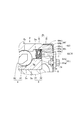
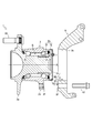
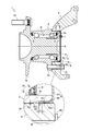
- the figure which shows some structures of the bearing device for wheels. The figure which shows the situation which attaches a cap member to the fitting cylinder part of an outer member.
- FIG. 1 is a diagram showing the structure of the wheel bearing device 1.
- FIG. 2 is a diagram showing a partial structure of the wheel bearing device 1.
- the wheel bearing device 1 rotatably supports the wheel.
- the wheel bearing device 1 includes an outer member 2, an inner member 3, and rolling members 4.5.
- the “inner side” refers to the vehicle body side of the wheel bearing device 1 when attached to the vehicle body
- the “outer side” refers to the wheel bearing device 1 when attached to the vehicle body. Indicates the wheel side.
- “radially outside” indicates a direction away from the rotation axis A of the inner member 3
- “radially inside” indicates a direction approaching the rotation axis A of the inner member 3.
- the “axial direction” indicates a direction along the rotation axis A of the inner member 3.
- the outer member 2 constitutes the outer ring portion of the rolling bearing structure.
- a fitting surface 2a is formed on the inner periphery of the outer member 2 at the inner end.
- a fitting surface 2b is formed on the inner periphery of the outer member 2 at the outer end.
- two outer raceway surfaces 2c and 2d are formed on the inner periphery of the outer member 2 at the axial center.
- the outer member 2 is formed with a vehicle body mounting flange 2e that extends radially outward.
- the vehicle body mounting flange 2e is provided with a plurality of bolt holes 2f.
- the inner member 3 constitutes an inner ring portion of the rolling bearing structure.
- the inner member 3 includes a hub wheel 31 and an inner wheel 32.
- the hub wheel 31 is disposed inside the outer member 2.
- An inner ring fitting portion 3a is formed on the outer periphery of the inner end of the hub wheel 31 up to the axial center portion.
- the inner ring fitting portion 3a indicates a portion where the outer diameter of the hub wheel 31 is reduced, and the outer peripheral surface thereof has a cylindrical shape around the rotation axis A.
- an opening 3b which is concave in a spherical shape is formed.
- an inner raceway surface 3d is formed on the outer periphery of the hub wheel 31 at the axial center.
- the hub wheel 31 is formed with a wheel mounting flange 3e that extends radially outward.
- the wheel mounting flange 3e is provided with a plurality of bolt holes 3f around the rotation axis A, and the hub bolt 33 is press-fitted into each of the bolt holes 3f.
- the inner ring 32 is fitted to the inner ring fitting portion 3a of the hub wheel 31 outside.
- a fitting surface 3g is formed on the outer periphery of the inner ring 32 at the inner end.
- An inner raceway surface 3c is formed on the outer periphery adjacent to the fitting surface 3g.
- the inner ring 32 is fixed by a caulking portion formed by pushing and expanding the tip of the inner ring fitting portion 3a in a state of being externally fitted to the inner ring fitting portion 3a.
- the rolling members 4 and 5 constitute rolling portions of the rolling bearing structure.
- the inner-side rolling member 4 includes a plurality of rolling elements 41 and one retainer 42.
- the outer rolling member 5 also includes a plurality of rolling elements 51 and one retainer 52.
- the rolling elements 41 and 51 are circularly arranged at equal intervals by retainers 42 and 52, respectively.
- the rolling element 41 constituting the inner rolling member 4 is interposed between the outer raceway surface 2c of the outer member 2 and the inner raceway surface 3c of the inner race 32.
- the rolling elements 51 constituting the outer-side rolling member 5 are interposed between the outer raceway surface 2d of the outer member 2 and the inner raceway surface 3d of the hub wheel 31.
- the retainers 42 and 52 are annular bodies in which pockets for accommodating the rolling elements 41 and 51 are formed at equal intervals.
- the retainer 42 constituting the inner-side rolling member 4 has a spherical wall extending between the rolling elements 41 adjacent to each other, and is held so as to sandwich one rolling element 41 between the two spherical walls. are doing.
- a spherical wall extends between the rolling elements 51 adjacent to each other, and one rolling element 51 is sandwiched between two spherical walls. Holding.
- the present wheel bearing device 1 includes a pair of seal members for sealing both open ends of an annular space S formed between the outer member 2 and the inner member 3 (the hub wheel 31 and the inner wheel 32). 6 is provided.
- the description will focus on the seal member 6 attached to the inner opening end of the annular space S.
- the seal member 6 includes a slinger 61 and a seal ring 62.
- the slinger 61 has a cylindrical fitting portion 61a that is fitted to the fitting surface 3g of the inner member 3 (the inner ring 32), and a disk-like shape extending radially outward from the inner end of the fitting portion 61a. And a side plate portion 61b.
- the encoder 63 is fixed to the side plate 61b of the slinger 61.
- the encoder 63 is an elastic member in which magnetic poles (N pole / S pole) are alternately arranged in the circumferential direction.
- the seal ring 62 is obtained by fixing an elastic member 65 to a metal core 64.
- the cored bar 64 includes a cylindrical fitting portion 64a that is fitted inside the fitting surface 2a of the outer member 2, and a disk-shaped side plate portion 64b that extends radially inward from an outer end of the fitting portion 64a.
- Side lips 65a and 65b are formed on the elastic member 65, and the leading edges thereof are in contact with the side plate portions 61b of the slinger 61 facing each other.
- a grease slip 65c is formed on the elastic member 65, and the leading edge thereof is in contact with or close to the fitting portion 61a of the opposed slinger 61.
- FIG. 3 is a diagram illustrating a situation in which the cap member 8 is mounted on the fitting cylindrical portion 2h of the outer member 2.
- the outer member 2 has a fitting cylindrical portion (generally referred to as a pilot portion) 2h formed at an inner end thereof.
- a cylindrical large-diameter portion 2i centered on the rotation axis A of the inner member 3 is formed on the outer side of the fitting cylinder 2h, and the inner member 3 is formed on the inner side of the fitting cylinder 2h.
- a cylindrical small-diameter portion 2j centering on the rotation axis A is formed. That is, the fitting cylindrical portion 2h has a cylindrical shape having different outer diameters in the axial direction (see FIGS. 1 and 2).
- the cap member 8 is formed by cutting and bending a metal steel plate by press working.
- the cap member 8 has a disc-shaped cover plate 81 centered on the rotation axis A of the inner member 3, and a cylinder centered on the rotation axis A extending from the radially outer end of the cover plate 81 to the outer side.
- a fitting portion 82 in a shape of a circle. Then, the fitting portion 82 is externally fitted to the small diameter portion 2j of the fitting cylindrical portion 2h.
- the fitting portion 82 slightly opens outward in the radial direction due to springback. Therefore, the fitting portion 82 has a tapered shape with a springback angle ⁇ with respect to the axial direction.
- FIG. 4 is a view showing a situation in which the fitting cylindrical portion 2h of the outer member 2 is fitted into the fitting hole 9h of the vehicle body-side member 9.
- the wheel bearing device 1 is fixed in a state where the fitting cylindrical portion 2h of the outer member 2 is fitted into the fitting hole 9h of the vehicle body side member 9. More specifically, in the bearing device 1 for a wheel, the fitting cylindrical portion 2h of the outer member 2 is fitted into the fitting hole 9h of the vehicle body-side member 9, and the inner side end face of the vehicle body mounting flange 2e is placed on the vehicle body side.
- the member 9 is fixed to the vehicle body-side member 9 by bolts 10 in a state where the member 9 is in contact with the outer end surface. At this time, the bolt 10 is inserted from the inner side into the through hole 9f of the vehicle body side member 9 and screwed into the bolt hole 2f of the vehicle body mounting flange 2e.
- the bolt 10 is inserted through the through hole of the vehicle body mounting flange 2 e from the outer side, and It is screwed into the bolt hole.
- the vehicle body side member 9 can be similarly fixed even if it is a motor case constituting an in-wheel motor.
- FIG. 5 is a diagram illustrating a main part shape of the cap member 8 according to the first embodiment.
- the cap member 8 according to the present embodiment is characterized in that a tapered portion 83 is provided on the outer peripheral edge at the outer end of the fitting portion 82 (see FIGS. 3 and 5).
- the tapered portion 83 is a portion that is inclined at a springback angle ⁇ so that the inclined surface 83s is reduced in diameter with respect to the fitting portion 82 whose diameter increases from the inner side to the outer side due to springback.
- the inclination angle of the tapered portion 83 is not limited to the springback angle ⁇ , and may be an angle close to the springback angle ⁇ .
- the large-diameter portion 2i is formed on the outer side of the fitting cylinder 2h, and the inner side of the fitting cylinder 2h. Is formed with a small diameter portion 2j.
- the cap member 8 is formed by bending a metal steel plate, and has a cover plate portion 81 that closes the inner-side open end of the outer member 2 and a fitting portion 82 that is fitted to the small-diameter portion 2j.
- a tapered portion 83 based on the springback angle ⁇ of the fitting portion 82 is provided on the outer peripheral edge of the outer end of the joining portion 82.
- the fitting cylindrical portion 2 h of the outer member 2 is fitted into the fitting hole 9 h of the vehicle body-side member 9, the fitting portion 82 of the cap member 8 is fitted with the fitting hole. It does not interfere with the inner peripheral edge of 9h, and as a result, the assemblability of the automobile can be improved.
- the outer diameters of the small diameter portion 2j and the fitting portion 82 are designed to be small in advance so that the fitting portion 82 does not interfere with the inner peripheral edge of the fitting hole 9h. Unlike the above, the strength of the fitting tubular portion 2h does not decrease.
- FIG. 6 is a diagram illustrating a main part shape of the cap member 8 according to the second embodiment.
- the tapered portion 83 is provided.
- the tapered portion 83 is a portion that is inclined at a predetermined angle with respect to the outer peripheral surface 82s of the fitting portion 82 whose diameter increases from the inner side toward the outer side so that the inclined surface 83s is reduced in diameter.
- R1 the angle of the outer peripheral surface 82s of the fitting portion 82 with respect to the rotation axis A of the inner member 3
- R2 the angle of the inclined surface 83s of the tapered portion 83 with respect to the outer peripheral surface 82s of the fitting portion 82.
- the relational expression R1 ⁇ R2 holds. It is obvious that the axial length L of the inclined surface 83s is set to be longer than the position where the fitting portion 82 of the cap member 8 interferes with the inner peripheral edge of the fitting hole 9h.
- the angle of the outer peripheral surface 82s of the fitting portion 82 with respect to the rotation axis A of the inner member 3 is R1, and the fitting is performed.
- the angle of the inclined surface 83s of the tapered portion 83 with respect to the outer peripheral surface 82s of the portion 82 is R2
- the relational expression R1 ⁇ R2 holds. According to the wheel bearing device 1, it is possible to reliably prevent the fitting portion 82 of the cap member 8 from interfering with the inner peripheral edge of the fitting hole 9h. Therefore, it is possible to further improve the assemblability of the automobile.
- FIG. 7 is a diagram illustrating a main part shape of the cap member 8 according to the third embodiment.
- the angle of the outer peripheral surface 82s of the fitting portion 82 with respect to the rotation axis A of the inner member 3 is R1
- the angle of the inclined surface 83s of the tapered portion 83 with respect to the outer peripheral surface 82s of the fitting portion 82 is R2.
- the relational expression R1 ⁇ R2 holds.
- the inner diameter of the fitting portion 82 is D1
- the outer diameter of the small diameter portion 2j is D2
- the relational expressions D1 ⁇ D2 and the relational expression D3 ⁇ D4 hold.
- the fitting portion 82 of the cap member 8 is formed on the inner peripheral edge of the fitting hole 9h. Interference can be reliably prevented. Accordingly, it is possible to prevent the cap member 8 from falling off and to further improve the assemblability of the automobile.
- the cap member 8 according to each embodiment is provided with two holes at predetermined positions of the cover plate portion 81.
- the radially outer hole is provided in a portion of the cover plate portion 81 facing the encoder 63, and the sensor 7 for detecting the magnetism of the encoder 63 is inserted into this hole (see FIGS. 1 to 7).
- a bolt 74 for fixing the sensor 7 is inserted into the hole on the radially inner side, and is screwed to a nut 84 welded to the cover plate 81 (see FIGS. 2 and 3).
- the cap member 8 according to each embodiment can support the sensor 7.
- since the fitting portion 82 does not interfere with the fitting hole 9h, no distortion is transmitted from the fitting portion 82 to the cover plate portion 81.
- the encoder 63 that rotates integrally with the inner member 3 and the magnetism of the encoder 63 that approaches the encoder 63 are generated.
- the cap member 8 supports the sensor 7. According to the wheel bearing device 1, since the cover plate portion 81 of the cap member 8 is not distorted, the gap between the encoder 63 and the sensor 7 does not vary.
- the present invention is applicable to a wheel bearing device.
Landscapes
- Engineering & Computer Science (AREA)
- General Engineering & Computer Science (AREA)
- Mechanical Engineering (AREA)
- Rolling Contact Bearings (AREA)
- Sealing Of Bearings (AREA)
- Mounting Of Bearings Or Others (AREA)
Abstract
外方部材の嵌合筒部を車体側部材の嵌合穴部に嵌め込む際に、キャップ部材の嵌合部が嵌合穴部の内周縁に干渉しない車輪用軸受装置を提供することを課題とする。外方部材(2)のインナー側端部に形成された嵌合筒部(2h)が車体側部材(9)の嵌合穴部(9h)に嵌め込まれた状態で固定される車輪用軸受装置(1)において、嵌合筒部(2h)のアウター側に大径部(2i)が形成され、嵌合筒部(2h)のインナー側に小径部(2j)が形成され、キャップ部材(8)は、金属鋼板を折り曲げて形成されていて、外方部材(2)のインナー側開口端を塞ぐ蓋板部(81)と小径部(2j)に外嵌される嵌合部(82)を有し、嵌合部(82)のアウター側端部における外周縁に嵌合部(82)のスプリングバック角度θに基づくテーパ加工部分(83)を設けた、ものである。
Description
本発明は、車輪用軸受装置に関する。
従来より、車輪を回転自在に支持する車輪用軸受装置が知られている。車輪用軸受装置は、外方部材の内側に内方部材が配置され、外方部材と内方部材のそれぞれの軌道面間に転動部材が介装されている。こうして、車輪用軸受装置は、転がり軸受構造を構成し、内方部材に取り付けられた車輪を回転自在としている。
ところで、車輪用軸受装置には、外方部材と内方部材の間に環状空間が形成されている。この環状空間に泥水が浸入した場合、泥水に含まれる砂塵等によって軌道面や転動部材が損傷するので、結果として軸受寿命が短くなる。そのため、このような車輪用軸受装置は、環状空間への泥水の浸入を防ぐべく、シール部材やキャップ部材を備えている(特許文献1及び特許文献2参照)。
特許文献1及び特許文献2に開示されたキャップ部材は、金属鋼板をプレス加工によって切り出し、かつ折り曲げることによって形成されている。キャップ部材は、外方部材のインナー側開口端を塞ぐ蓋板部と、外方部材の嵌合筒部に外嵌される嵌合部と、を有している。なお、キャップ部材には、泥水の浸入を防ぐためだけでなく、センサを支持する役割を兼ねたものが存在している。
加えて、このような車輪用軸受装置は、外方部材の嵌合筒部が車体側部材の嵌合穴部に嵌め込まれた状態で固定される。そのため、外方部材の嵌合筒部を車体側部材の嵌合穴部にスムーズに嵌め込むことができれば、自動車の組立性向上につながる。しかし、キャップ部材の嵌合部がスプリングバック等によって径方向外側へ開くと、この嵌合部が嵌合穴部の内周縁に干渉してスムーズに嵌め込めない場合があった(図8参照)。そこで、外方部材の嵌合筒部を車体側部材の嵌合穴部に嵌め込む際に、キャップ部材の嵌合部が嵌合穴部の内周縁に干渉せず、ひいては自動車の組立性向上を実現できる車輪用軸受装置が求められていた。
外方部材の嵌合筒部を車体側部材の嵌合穴部に嵌め込む際に、キャップ部材の嵌合部が嵌合穴部の内周縁に干渉せず、ひいては自動車の組立性向上を実現できる車輪用軸受装置を提供する。
第一の発明は、
外側軌道面が形成された外方部材と、
ハブ輪及び当該ハブ輪に外嵌される少なくとも一つの内輪からなり、内側軌道面が形成された内方部材と、
前記外方部材と前記内方部材のそれぞれの軌道面間に介装される転動部材と、
前記外方部材に外嵌されるキャップ部材と、を備え、
前記外方部材のインナー側端部に形成された嵌合筒部が車体側部材の嵌合穴部に嵌め込まれた状態で固定される車輪用軸受装置において、
前記嵌合筒部のアウター側に大径部が形成され、
前記嵌合筒部のインナー側に小径部が形成され、
前記キャップ部材は、金属鋼板を折り曲げて形成されていて、前記外方部材のインナー側開口端を塞ぐ蓋板部と前記小径部に外嵌される嵌合部を有し、前記嵌合部のアウター側端部における外周縁に当該嵌合部のスプリングバック角度に基づくテーパ加工部分を設けた、ものである。
外側軌道面が形成された外方部材と、
ハブ輪及び当該ハブ輪に外嵌される少なくとも一つの内輪からなり、内側軌道面が形成された内方部材と、
前記外方部材と前記内方部材のそれぞれの軌道面間に介装される転動部材と、
前記外方部材に外嵌されるキャップ部材と、を備え、
前記外方部材のインナー側端部に形成された嵌合筒部が車体側部材の嵌合穴部に嵌め込まれた状態で固定される車輪用軸受装置において、
前記嵌合筒部のアウター側に大径部が形成され、
前記嵌合筒部のインナー側に小径部が形成され、
前記キャップ部材は、金属鋼板を折り曲げて形成されていて、前記外方部材のインナー側開口端を塞ぐ蓋板部と前記小径部に外嵌される嵌合部を有し、前記嵌合部のアウター側端部における外周縁に当該嵌合部のスプリングバック角度に基づくテーパ加工部分を設けた、ものである。
第二の発明は、第一の発明に係る車輪用軸受装置において、
前記内方部材の回転軸に対する前記嵌合部の外周面の角度をR1とし、
前記嵌合部の外周面に対する前記テーパ加工部分の傾斜面の角度をR2とすると、
関係式R1≦R2が成立する、ものである。
前記内方部材の回転軸に対する前記嵌合部の外周面の角度をR1とし、
前記嵌合部の外周面に対する前記テーパ加工部分の傾斜面の角度をR2とすると、
関係式R1≦R2が成立する、ものである。
第三の発明は、第一又は第二の発明に係る車輪用軸受装置において、
前記嵌合部における内径をD1とし、
前記小径部における外径をD2とし、
前記嵌合部における外径をD3とし、
前記大径部における外径をD4とすると、
関係式D1≦D2かつ関係式D3≦D4が成立する、ものである。
前記嵌合部における内径をD1とし、
前記小径部における外径をD2とし、
前記嵌合部における外径をD3とし、
前記大径部における外径をD4とすると、
関係式D1≦D2かつ関係式D3≦D4が成立する、ものである。
第四の発明は、第一から第三のいずれかの発明に係る車輪用軸受装置において、
前記内方部材と一体になって回転するエンコーダと、
前記エンコーダに近接して当該エンコーダの磁気を検出するセンサと、を具備し、
前記キャップ部材が前記センサを支持する、ものである。
前記内方部材と一体になって回転するエンコーダと、
前記エンコーダに近接して当該エンコーダの磁気を検出するセンサと、を具備し、
前記キャップ部材が前記センサを支持する、ものである。
本発明の効果として、以下に示すような効果を奏する。
第一の発明に係る車輪用軸受装置においては、嵌合筒部のアウター側に大径部が形成され、嵌合筒部のインナー側に小径部が形成されている。そして、キャップ部材は、金属鋼板を折り曲げて形成されていて、外方部材のインナー側開口端を塞ぐ蓋板部と小径部に外嵌される嵌合部を有し、嵌合部のアウター側端部における外周縁に嵌合部のスプリングバック角度に基づくテーパ加工部分を設けたものである。かかる車輪用軸受装置によれば、外方部材の嵌合筒部を車体側部材の嵌合穴部に嵌め込む際に、キャップ部材の嵌合部が嵌合穴部の内周縁に干渉せず、ひいては自動車の組立性向上を実現できる。
第二の発明に係る車輪用軸受装置においては、内方部材の回転軸に対する嵌合部の外周面の角度をR1とし、嵌合部の外周面に対するテーパ加工部分の傾斜面の角度をR2とすると、関係式R1≦R2が成立する。かかる車輪用軸受装置によれば、キャップ部材の嵌合部が嵌合穴部の内周縁に干渉するのを確実に防ぐことができる。従って、更なる自動車の組立性向上を実現できる。
第三の発明に係る車輪用軸受装置においては、嵌合部における内径をD1とし、小径部における外径をD2とし、嵌合部における外径をD3とし、大径部における外径をD4とすると、関係式D1≦D2かつ関係式D3≦D4が成立する。かかる車輪用軸受装置によれば、嵌合部を小径部に強く押し込んで脱落を防ぐ設計であったとしても、キャップ部材の嵌合部が嵌合穴部の内周縁に干渉するのを確実に防ぐことができる。従って、キャップ部材の脱落を防ぐとともに、更なる自動車の組立性向上を実現できる。
第四の発明に係る車輪用軸受装置においては、内方部材と一体になって回転するエンコーダと、エンコーダに近接してエンコーダの磁気を検出するセンサと、を具備している。そして、キャップ部材がセンサを支持するものである。かかる車輪用軸受装置によれば、キャップ部材の蓋板部に歪みが生じないので、エンコーダとセンサの隙間にバラツキが生じない。
本発明に係る車輪用軸受装置1について説明する。図1は、車輪用軸受装置1の構造を示す図である。図2は、車輪用軸受装置1の一部構造を示す図である。
車輪用軸受装置1は、車輪を回転自在に支持するものである。車輪用軸受装置1は、外方部材2と、内方部材3と、転動部材4・5と、を備えている。なお、本明細書において、「インナー側」とは、車体に取り付けた際の車輪用軸受装置1の車体側を表し、「アウター側」とは、車体に取り付けた際の車輪用軸受装置1の車輪側を表す。また、「径方向外側」とは、内方部材3の回転軸Aから遠ざかる方向を表し、「径方向内側」とは、内方部材3の回転軸Aに近づく方向を表す。更に、「軸方向」とは、内方部材3の回転軸Aに沿う方向を表す。
外方部材2は、転がり軸受構造の外輪部分を構成するものである。外方部材2のインナー側端部における内周には、嵌合面2aが形成されている。また、外方部材2のアウター側端部における内周には、嵌合面2bが形成されている。更に、外方部材2の軸方向中央部における内周には、二つの外側軌道面2c・2dが形成されている。加えて、外方部材2には、径方向外側へ広がる車体取り付けフランジ2eが形成されている。車体取り付けフランジ2eには、複数のボルト穴2fが設けられている。
内方部材3は、転がり軸受構造の内輪部分を構成するものである。内方部材3は、ハブ輪31と内輪32で構成されている。
ハブ輪31は、外方部材2の内側に配置される。ハブ輪31のインナー側端部における外周には、軸方向中央部まで内輪嵌合部3aが形成されている。内輪嵌合部3aは、ハブ輪31の外径が小さくなった部分を指し、その外周面が回転軸Aを中心とする円筒形状となっている。また、ハブ輪31のアウター側端面における中央には、球面状に窪んだ開口穴3bが形成されている。更に、ハブ輪31の軸方向中央部における外周には、内側軌道面3dが形成されている。加えて、ハブ輪31には、径方向外側へ広がる車輪取り付けフランジ3eが形成されている。車輪取り付けフランジ3eには、回転軸Aを中心に複数のボルト穴3fが設けられており、それぞれのボルト穴3fにハブボルト33が圧入されている。
内輪32は、ハブ輪31の内輪嵌合部3aに外嵌される。内輪32のインナー側端部における外周には、嵌合面3gが形成されている。また、嵌合面3gに隣接する外周には、内側軌道面3cが形成されている。なお、内輪32は、内輪嵌合部3aに外嵌された状態で、この内輪嵌合部3aの先端を押し広げて形成された加締部によって固定されている。
転動部材4・5は、転がり軸受構造の転動部分を構成するものである。インナー側の転動部材4は、複数の転動体41と一つの保持器42で構成されている。同様に、アウター側の転動部材5も、複数の転動体51と一つの保持器52で構成されている。
転動体41・51は、それぞれが保持器42・52によって円形かつ等間隔にならべられている。インナー側の転動部材4を構成する転動体41は、外方部材2の外側軌道面2cと内輪32の内側軌道面3cの間に介装されている。また、アウター側の転動部材5を構成する転動体51は、外方部材2の外側軌道面2dとハブ輪31の内側軌道面3dの間に介装されている。
保持器42・52は、転動体41・51を収めるためのポケットが等間隔に形成された円環体となっている。インナー側の転動部材4を構成する保持器42は、互いに隣り合う転動体41と転動体41の間に球面壁が延びており、二つの球面壁によって一つの転動体41を挟み込むように保持している。また、アウター側の転動部材5を構成する保持器52は、互いに隣り合う転動体51と転動体51の間に球面壁が延びており、二つの球面壁によって一つの転動体51を挟み込むように保持している。
加えて、本車輪用軸受装置1は、外方部材2と内方部材3(ハブ輪31及び内輪32)の間に形成される環状空間Sの両側開口端を密封すべく、一対のシール部材6を備えている。ここでは、環状空間Sのインナー側開口端に装着されるシール部材6に着目して説明する。
シール部材6は、スリンガ61とシールリング62で構成されている。スリンガ61は、内方部材3(内輪32)の嵌合面3gに外嵌される円筒状の嵌合部61aと、嵌合部61aのインナー側端部から径方向外側へ延びる円板状の側板部61bと、を有している。なお、このスリンガ61の側板部61bには、エンコーダ63が固着している。エンコーダ63は、周方向に磁極(N極・S極)を交互に配列した弾性部材である。
一方、シールリング62は、芯金64に弾性部材65を固着したものである。芯金64は、外方部材2の嵌合面2aに内嵌される円筒状の嵌合部64aと、嵌合部64aのアウター側端部から径方向内側へ延びる円板状の側板部64bと、を有している。弾性部材65には、サイドリップ65a・65bが形成されており、それぞれの先端縁が対向するスリンガ61の側板部61bに接触している。更に、弾性部材65には、グリースリップ65cが形成されており、その先端縁が対向するスリンガ61の嵌合部61aに接触又は近接している。
更に加えて、本車輪用軸受装置1は、外方部材2のインナー側開口端を塞ぐことによってシール部材6に泥水が到達するのを防ぐべく、キャップ部材8を備えている。以下では、外方部材2の嵌合筒部2hにキャップ部材8を装着できる構造について説明する。図3は、外方部材2の嵌合筒部2hにキャップ部材8を装着する状況を示す図である。
外方部材2は、そのインナー側端部に嵌合筒部(一般的にパイロット部という)2hが形成されている。嵌合筒部2hにおけるアウター側には、内方部材3の回転軸Aを中心とする円筒状の大径部2iが形成され、嵌合筒部2hにおけるインナー側には、内方部材3の回転軸Aを中心とする円筒状の小径部2jが形成されている。つまり、嵌合筒部2hは、軸方向で外径寸法が異なった円筒形状となっている(図1及び図2参照)。
他方、キャップ部材8は、金属鋼板をプレス加工によって切り出し、かつ折り曲げることによって形成されている。キャップ部材8は、内方部材3の回転軸Aを中心とする円板状の蓋板部81と、蓋板部81の径方向外側端部からアウター側へ延びる回転軸Aを中心とする円筒状の嵌合部82と、を有している。そして、この嵌合部82が嵌合筒部2hの小径部2jに外嵌される。なお、嵌合部82は、いわゆるスプリングバックによって僅かながらも径方向外側へ開いてしまう。そのため、嵌合部82は、軸方向に対してスプリングバック角度θのテーパ形状となる。また、嵌合部82における内径をD1とし、小径部2jにおける外径をD2とした場合、関係式D1≦D2が成立する。こうすることで、キャップ部材8の脱落を防ぐことができる。
ここで、車輪用軸受装置1を車体側部材(一般的にナックルという)9に取り付け可能とした構造について説明する。図4は、外方部材2の嵌合筒部2hを車体側部材9の嵌合穴部9hに嵌め込む状況を示す図である。
車輪用軸受装置1は、外方部材2の嵌合筒部2hを車体側部材9の嵌合穴部9hに嵌め込んだ状態で固定される。具体的に説明すると、車輪用軸受装置1は、外方部材2の嵌合筒部2hを車体側部材9の嵌合穴部9hに嵌め込むとともに、車体取り付けフランジ2eのインナー側端面を車体側部材9のアウター側端面に当接させた状態で、ボルト10によって車体側部材9に固定される。このとき、ボルト10は、車体側部材9の貫通穴9fにインナー側から挿通され、車体取り付けフランジ2eのボルト穴2fに螺合される。但し、車体取り付けフランジ2eに貫通穴が設けられ、車体側部材9にボルト穴が設けられている場合は、ボルト10が車体取り付けフランジ2eの貫通穴にアウター側から挿通され、車体側部材9のボルト穴に螺合される。なお、車体側部材9がインホイールモータを構成するモータケースであったとしても同様に固定することが可能である。
次に、第一実施形態に係るキャップ部材8の特徴とその効果について説明する。図5は、第一実施形態に係るキャップ部材8の要部形状を示す図である。
本実施形態に係るキャップ部材8は、嵌合部82のアウター側端部における外周縁にテーパ加工部分83を設けた点を特徴とする(図3及び図5参照)。かかるテーパ加工部分83は、スプリングバックによってインナー側からアウター側に向かって拡径する嵌合部82に対し、その傾斜面83sが縮径するようにスプリングバック角度θで傾斜した部位である。但し、本実施形態に係るキャップ部材8は、テーパ加工部分83の傾斜角度がスプリングバック角度θに限定するものではなく、スプリングバック角度θに近似した角度でもよいものとする。これは、外方部材2の嵌合筒部2hを車体側部材9の嵌合穴部9hに嵌め込む際に、キャップ部材8の嵌合部82が嵌合穴部9hの内周縁に干渉するのを回避できればよいからである。
以上のように、第一実施形態に係るキャップ部材8を備えた車輪用軸受装置1においては、嵌合筒部2hのアウター側に大径部2iが形成され、嵌合筒部2hのインナー側に小径部2jが形成されている。そして、キャップ部材8は、金属鋼板を折り曲げて形成されていて、外方部材2のインナー側開口端を塞ぐ蓋板部81と小径部2jに外嵌される嵌合部82を有し、嵌合部82のアウター側端部における外周縁に嵌合部82のスプリングバック角度θに基づくテーパ加工部分83を設けたものである。かかる車輪用軸受装置1によれば、外方部材2の嵌合筒部2hを車体側部材9の嵌合穴部9hに嵌め込む際に、キャップ部材8の嵌合部82が嵌合穴部9hの内周縁に干渉せず、ひいては自動車の組立性向上を実現できる。
加えて、かかる車輪用軸受装置1によれば、小径部2j及び嵌合部82の外径を予め小さく設計して嵌合部82が嵌合穴部9hの内周縁に干渉しないようにしたものとは異なり、嵌合筒部2hの強度が低下したりしない。
次に、第二実施形態に係るキャップ部材8の特徴とその効果について説明する。図6は、第二実施形態に係るキャップ部材8の要部形状を示す図である。
本実施形態に係るキャップ部材8においても、テーパ加工部分83が設けられている。かかるテーパ加工部分83は、インナー側からアウター側に向かって拡径する嵌合部82の外周面82sに対し、その傾斜面83sが縮径するように所定角度で傾斜した部位である。ここでは、内方部材3の回転軸Aに対する嵌合部82の外周面82sの角度をR1とし、嵌合部82の外周面82sに対するテーパ加工部分83の傾斜面83sの角度をR2とすると、関係式R1≦R2が成立するものとなっている。なお、傾斜面83sの軸方向長さLは、キャップ部材8の嵌合部82が嵌合穴部9hの内周縁に干渉する位置よりも長く設定されるのは明白である。
以上のように、第二実施形態に係るキャップ部材8を備えた車輪用軸受装置1においては、内方部材3の回転軸Aに対する嵌合部82の外周面82sの角度をR1とし、嵌合部82の外周面82sに対するテーパ加工部分83の傾斜面83sの角度をR2とすると、関係式R1≦R2が成立する。かかる車輪用軸受装置1によれば、キャップ部材8の嵌合部82が嵌合穴部9hの内周縁に干渉するのを確実に防ぐことができる。従って、更なる自動車の組立性向上を実現できる。
次に、第三実施形態に係るキャップ部材8の特徴とその効果について説明する。但し、第二実施形態に係るキャップ部材8と異なる部分についてのみ説明する。図7は、第三実施形態に係るキャップ部材8の要部形状を示す図である。
本実施形態においても、内方部材3の回転軸Aに対する嵌合部82の外周面82sの角度をR1とし、嵌合部82の外周面82sに対するテーパ加工部分83の傾斜面83sの角度をR2とすると、関係式R1≦R2が成立するものとなっている。また、前述した関係式D1≦D2が成立する場合は、キャップ部材8の装着時に嵌合部82が径方向外側へより開いてしまうのであるが、嵌合部82における外径をD3とし、大径部2iにおける外径をD4とすると、関係式D3≦D4が成立するものとなっている。
以上のように、第三実施形態に係るキャップ部材8を備えた車輪用軸受装置1においては、嵌合部82における内径をD1とし、小径部2jにおける外径をD2とし、嵌合部82における外径をD3とし、大径部2iにおける外径をD4とすると、関係式D1≦D2かつ関係式D3≦D4が成立する。かかる車輪用軸受装置1によれば、嵌合部82を小径部2jに強く押し込んで脱落を防ぐ設計であったとしても、キャップ部材8の嵌合部82が嵌合穴部9hの内周縁に干渉するのを確実に防ぐことができる。従って、キャップ部材8の脱落を防ぐとともに、更なる自動車の組立性向上を実現できる。
次に、各実施形態に係るキャップ部材8の他の特徴とその効果について説明する。
各実施形態に係るキャップ部材8は、蓋板部81の所定箇所に二つの穴が設けられている。径方向外側の穴は、蓋板部81のエンコーダ63に対向する部分に設けられており、この穴にはエンコーダ63の磁気を検出するセンサ7が挿入される(図1から図7参照)。また、径方向内側の穴には、センサ7を固定するためのボルト74が挿通され、蓋板部81に溶接されたナット84に螺合される(図2及び図3参照)。こうして、各実施形態に係るキャップ部材8は、センサ7を支持することができるのである。なお、各実施形態に係るキャップ部材8は、嵌合部82が嵌合穴部9hに干渉しないので、嵌合部82から蓋板部81へ歪が伝わることがない。
以上のように、本実施形態に係るキャップ部材8を備えた車輪用軸受装置1においては、内方部材3と一体になって回転するエンコーダ63と、エンコーダ63に近接してエンコーダ63の磁気を検出するセンサ7と、を具備している。そして、キャップ部材8がセンサ7を支持するものである。かかる車輪用軸受装置1によれば、キャップ部材8の蓋板部81に歪みが生じないので、エンコーダ63とセンサ7の隙間にバラツキが生じない。
本発明は、車輪用軸受装置に利用可能である。
1 車輪用軸受装置
2 外方部材、 2c 外側軌道面、 2d 外側軌道面、 2h 嵌合筒部、 2i 大径部、 2j 小径部
3 内方部材、 31 ハブ輪、 32 内輪、 3c 内側軌道面、 3d 内側軌道面
4 転動部材
5 転動部材
6 シール部材、 63 エンコーダ
7 センサ
8 キャップ部材、 81 蓋板部、 82 嵌合部、 83 テーパ加工部分
9 車体側部材、 9h 嵌合穴部
A 内方部材の回転軸
θ スプリングバック角度
R1 内方部材の回転軸に対する嵌合部の外周面の角度
R2 嵌合部の外周面に対するテーパ加工部分の傾斜面の角度
D1 嵌合部における内径
D2 小径部における外径
D3 嵌合部における外径
D4 大径部における外径
2 外方部材、 2c 外側軌道面、 2d 外側軌道面、 2h 嵌合筒部、 2i 大径部、 2j 小径部
3 内方部材、 31 ハブ輪、 32 内輪、 3c 内側軌道面、 3d 内側軌道面
4 転動部材
5 転動部材
6 シール部材、 63 エンコーダ
7 センサ
8 キャップ部材、 81 蓋板部、 82 嵌合部、 83 テーパ加工部分
9 車体側部材、 9h 嵌合穴部
A 内方部材の回転軸
θ スプリングバック角度
R1 内方部材の回転軸に対する嵌合部の外周面の角度
R2 嵌合部の外周面に対するテーパ加工部分の傾斜面の角度
D1 嵌合部における内径
D2 小径部における外径
D3 嵌合部における外径
D4 大径部における外径
Claims (4)
- 外側軌道面が形成された外方部材と、
ハブ輪及び当該ハブ輪に外嵌される少なくとも一つの内輪からなり、内側軌道面が形成された内方部材と、
前記外方部材と前記内方部材のそれぞれの軌道面間に介装される転動部材と、
前記外方部材に外嵌されるキャップ部材と、を備え、
前記外方部材のインナー側端部に形成された嵌合筒部が車体側部材の嵌合穴部に嵌め込まれた状態で固定される車輪用軸受装置において、
前記嵌合筒部のアウター側に大径部が形成され、
前記嵌合筒部のインナー側に小径部が形成され、
前記キャップ部材は、金属鋼板を折り曲げて形成されていて、前記外方部材のインナー側開口端を塞ぐ蓋板部と前記小径部に外嵌される嵌合部を有し、前記嵌合部のアウター側端部における外周縁に当該嵌合部のスプリングバック角度に基づくテーパ加工部分を設けた、ことを特徴とする車輪用軸受装置。 - 前記内方部材の回転軸に対する前記嵌合部の外周面の角度をR1とし、
前記嵌合部の外周面に対する前記テーパ加工部分の外周面の角度をR2とすると、
関係式R1≦R2が成立する、ことを特徴とする請求項1に記載の車輪用軸受装置。 - 前記嵌合部における内径をD1とし、
前記小径部における外径をD2とし、
前記嵌合部における外径をD3とし、
前記大径部における外径をD4とすると、
関係式D1≦D2かつ関係式D3≦D4が成立する、ことを特徴とする請求項1又は請求項2に記載の車輪用軸受装置。 - 前記内方部材と一体になって回転するエンコーダと、
前記エンコーダに近接して当該エンコーダの磁気を検出するセンサと、を具備し、
前記キャップ部材が前記センサを支持する、ことを特徴とする請求項1から請求項3のいずれか一項に記載の車輪用軸受装置。
Priority Applications (3)
| Application Number | Priority Date | Filing Date | Title |
|---|---|---|---|
| US17/264,614 US11298976B2 (en) | 2018-08-16 | 2019-08-06 | Bearing device for vehicle wheel |
| CN201980051746.6A CN112513483B (zh) | 2018-08-16 | 2019-08-06 | 车轮用轴承装置 |
| DE112019004122.3T DE112019004122T5 (de) | 2018-08-16 | 2019-08-06 | Lagervorrichtung für ein Fahrzeugrad |
Applications Claiming Priority (2)
| Application Number | Priority Date | Filing Date | Title |
|---|---|---|---|
| JP2018-153304 | 2018-08-16 | ||
| JP2018153304A JP6968044B2 (ja) | 2018-08-16 | 2018-08-16 | 車輪用軸受装置 |
Publications (1)
| Publication Number | Publication Date |
|---|---|
| WO2020036093A1 true WO2020036093A1 (ja) | 2020-02-20 |
Family
ID=69524803
Family Applications (1)
| Application Number | Title | Priority Date | Filing Date |
|---|---|---|---|
| PCT/JP2019/030821 Ceased WO2020036093A1 (ja) | 2018-08-16 | 2019-08-06 | 車輪用軸受装置 |
Country Status (5)
| Country | Link |
|---|---|
| US (1) | US11298976B2 (ja) |
| JP (1) | JP6968044B2 (ja) |
| CN (1) | CN112513483B (ja) |
| DE (1) | DE112019004122T5 (ja) |
| WO (1) | WO2020036093A1 (ja) |
Families Citing this family (1)
| Publication number | Priority date | Publication date | Assignee | Title |
|---|---|---|---|---|
| CN119551067B (zh) * | 2024-08-30 | 2026-03-17 | 中国第一汽车股份有限公司 | 转向节和轮毂轴承的一体化结构、轮边总成和车辆 |
Citations (4)
| Publication number | Priority date | Publication date | Assignee | Title |
|---|---|---|---|---|
| JP2010101332A (ja) * | 2008-10-21 | 2010-05-06 | Ntn Corp | 嵌合環およびそれを備えた車輪用軸受装置 |
| KR20120046534A (ko) * | 2010-11-02 | 2012-05-10 | 주식회사 일진글로벌 | 휠 베어링용 실링 캡 |
| JP2015137754A (ja) * | 2014-01-24 | 2015-07-30 | Ntn株式会社 | 車輪用軸受装置 |
| JP2017053389A (ja) * | 2015-09-08 | 2017-03-16 | 株式会社ジェイテクト | 車輪用軸受装置 |
Family Cites Families (18)
| Publication number | Priority date | Publication date | Assignee | Title |
|---|---|---|---|---|
| IT227681Y1 (it) * | 1992-11-13 | 1997-12-15 | Skf Ind Spa | Dispositivo di trattenimento per sensori di rilevamento del movimento reciproco tra due organi in rotazione relativa. |
| JP2000018241A (ja) * | 1998-07-06 | 2000-01-18 | Nippon Seiko Kk | 回転速度検出装置付転がり軸受ユニット |
| JP2001315501A (ja) * | 2000-05-08 | 2001-11-13 | Ntn Corp | 車輪軸受装置 |
| JP2002347406A (ja) * | 2001-05-29 | 2002-12-04 | Nsk Ltd | 車輪用軸受ユニットとその製造方法 |
| JP3985617B2 (ja) * | 2002-07-17 | 2007-10-03 | 株式会社ジェイテクト | 転がり軸受装置 |
| JP4656917B2 (ja) * | 2004-11-11 | 2011-03-23 | Ntn株式会社 | 回転速度検出装置付車輪用軸受装置 |
| BR112012004313B1 (pt) * | 2009-10-06 | 2021-01-12 | Nsk Ltd | Suporte de unidade de cubo |
| JP2012087858A (ja) * | 2010-10-19 | 2012-05-10 | Ntn Corp | 車輪用軸受装置 |
| JP2012188090A (ja) * | 2011-03-14 | 2012-10-04 | Ntn Corp | 車輪用軸受装置 |
| JP5842536B2 (ja) * | 2011-10-26 | 2016-01-13 | 日本精工株式会社 | 車輪用回転支持装置 |
| JP2014139053A (ja) * | 2013-01-21 | 2014-07-31 | Nsk Ltd | ラックアンドピニオン式ステアリングギヤユニット |
| US20160016702A1 (en) * | 2013-03-15 | 2016-01-21 | Sabert Corporation | Resealable Leak-Resistant Containers Having A Pressed Pulp Tray With A Thermoformed Plastic Lid |
| WO2014157537A1 (ja) * | 2013-03-27 | 2014-10-02 | Ntn株式会社 | 車輪用軸受装置 |
| JP6290543B2 (ja) * | 2013-04-03 | 2018-03-07 | Ntn株式会社 | 車輪用軸受装置 |
| EP2990673B1 (en) * | 2014-08-26 | 2017-05-31 | Aktiebolaget SKF | Rolling bearing unit with an encoder and protective cover with a sensor for a vehicle wheel hub |
| JP6398484B2 (ja) * | 2014-09-02 | 2018-10-03 | 日本精工株式会社 | エンコーダ付転がり軸受ユニット |
| JP2016078512A (ja) * | 2014-10-10 | 2016-05-16 | Ntn株式会社 | 車輪用軸受装置 |
| JP6711510B2 (ja) * | 2016-02-18 | 2020-06-17 | 内山工業株式会社 | 嵌合部材及びこれを備えた軸受装置 |
-
2018
- 2018-08-16 JP JP2018153304A patent/JP6968044B2/ja active Active
-
2019
- 2019-08-06 DE DE112019004122.3T patent/DE112019004122T5/de active Pending
- 2019-08-06 WO PCT/JP2019/030821 patent/WO2020036093A1/ja not_active Ceased
- 2019-08-06 CN CN201980051746.6A patent/CN112513483B/zh active Active
- 2019-08-06 US US17/264,614 patent/US11298976B2/en active Active
Patent Citations (4)
| Publication number | Priority date | Publication date | Assignee | Title |
|---|---|---|---|---|
| JP2010101332A (ja) * | 2008-10-21 | 2010-05-06 | Ntn Corp | 嵌合環およびそれを備えた車輪用軸受装置 |
| KR20120046534A (ko) * | 2010-11-02 | 2012-05-10 | 주식회사 일진글로벌 | 휠 베어링용 실링 캡 |
| JP2015137754A (ja) * | 2014-01-24 | 2015-07-30 | Ntn株式会社 | 車輪用軸受装置 |
| JP2017053389A (ja) * | 2015-09-08 | 2017-03-16 | 株式会社ジェイテクト | 車輪用軸受装置 |
Also Published As
| Publication number | Publication date |
|---|---|
| CN112513483B (zh) | 2022-09-13 |
| JP2020026871A (ja) | 2020-02-20 |
| DE112019004122T5 (de) | 2021-05-20 |
| JP6968044B2 (ja) | 2021-11-17 |
| US11298976B2 (en) | 2022-04-12 |
| CN112513483A (zh) | 2021-03-16 |
| US20210293278A1 (en) | 2021-09-23 |
Similar Documents
| Publication | Publication Date | Title |
|---|---|---|
| US7175349B2 (en) | Wheel rotation supporting apparatus | |
| WO2012176849A1 (ja) | 車輪用軸受装置 | |
| JP2018071644A (ja) | 車輪支持用転がり軸受ユニット | |
| JP2017036740A (ja) | 密封装置 | |
| JP5328136B2 (ja) | 車輪用軸受 | |
| JP2020051597A (ja) | 車輪用軸受装置 | |
| JP2020026871A (ja) | 車輪用軸受装置 | |
| CN104747592A (zh) | 车轮用轴承装置 | |
| CN110446870A (zh) | 车轮用轴承装置 | |
| JP7046514B2 (ja) | 密封装置 | |
| JP2019163848A (ja) | 車輪用軸受装置 | |
| JP2020020351A (ja) | 車輪支持用転がり軸受ユニット | |
| JP2020159399A (ja) | 車輪用軸受装置 | |
| JP2020037984A (ja) | 車輪用軸受装置 | |
| CN207229605U (zh) | 车轮支承用滚动轴承单元 | |
| JP6483460B2 (ja) | 密封装置およびこれを備えた車輪用軸受装置 | |
| WO2019142806A1 (ja) | 車輪用軸受装置 | |
| JP6912860B2 (ja) | 車輪用軸受装置 | |
| JP2019138396A (ja) | 密封装置の組み立て方法 | |
| WO2018154999A1 (ja) | 車輪用軸受装置 | |
| JP2022126301A (ja) | 車輪用軸受装置 | |
| JP6725993B2 (ja) | 車輪用軸受装置 | |
| JP2024089975A (ja) | 車輪用軸受装置 | |
| JP2017187081A (ja) | 車輪用軸受装置 | |
| JP5715171B2 (ja) | 軸受密封装置および車輪用軸受 |
Legal Events
| Date | Code | Title | Description |
|---|---|---|---|
| 121 | Ep: the epo has been informed by wipo that ep was designated in this application |
Ref document number: 19849798 Country of ref document: EP Kind code of ref document: A1 |
|
| 122 | Ep: pct application non-entry in european phase |
Ref document number: 19849798 Country of ref document: EP Kind code of ref document: A1 |