WO2020031637A1 - ねじ軸およびその製造方法、並びに、ステアリングホイールの電動位置調節装置およびその製造方法 - Google Patents
ねじ軸およびその製造方法、並びに、ステアリングホイールの電動位置調節装置およびその製造方法 Download PDFInfo
- Publication number
- WO2020031637A1 WO2020031637A1 PCT/JP2019/028104 JP2019028104W WO2020031637A1 WO 2020031637 A1 WO2020031637 A1 WO 2020031637A1 JP 2019028104 W JP2019028104 W JP 2019028104W WO 2020031637 A1 WO2020031637 A1 WO 2020031637A1
- Authority
- WO
- WIPO (PCT)
- Prior art keywords
- rolling
- shaft portion
- diameter
- screw
- diameter shaft
- Prior art date
- Legal status (The legal status is an assumption and is not a legal conclusion. Google has not performed a legal analysis and makes no representation as to the accuracy of the status listed.)
- Ceased
Links
Images



Classifications
-
- B—PERFORMING OPERATIONS; TRANSPORTING
- B62—LAND VEHICLES FOR TRAVELLING OTHERWISE THAN ON RAILS
- B62D—MOTOR VEHICLES; TRAILERS
- B62D1/00—Steering controls, i.e. means for initiating a change of direction of the vehicle
- B62D1/02—Steering controls, i.e. means for initiating a change of direction of the vehicle vehicle-mounted
- B62D1/16—Steering columns
- B62D1/18—Steering columns yieldable or adjustable, e.g. tiltable
- B62D1/181—Steering columns yieldable or adjustable, e.g. tiltable with power actuated adjustment, e.g. with position memory
-
- B—PERFORMING OPERATIONS; TRANSPORTING
- B21—MECHANICAL METAL-WORKING WITHOUT ESSENTIALLY REMOVING MATERIAL; PUNCHING METAL
- B21H—MAKING PARTICULAR METAL OBJECTS BY ROLLING, e.g. SCREWS, WHEELS, RINGS, BARRELS, BALLS
- B21H3/00—Making helical bodies or bodies having parts of helical shape
- B21H3/02—Making helical bodies or bodies having parts of helical shape external screw-threads ; Making dies for thread rolling
- B21H3/04—Making by means of profiled-rolls or die rolls
-
- B—PERFORMING OPERATIONS; TRANSPORTING
- B21—MECHANICAL METAL-WORKING WITHOUT ESSENTIALLY REMOVING MATERIAL; PUNCHING METAL
- B21H—MAKING PARTICULAR METAL OBJECTS BY ROLLING, e.g. SCREWS, WHEELS, RINGS, BARRELS, BALLS
- B21H3/00—Making helical bodies or bodies having parts of helical shape
- B21H3/02—Making helical bodies or bodies having parts of helical shape external screw-threads ; Making dies for thread rolling
- B21H3/04—Making by means of profiled-rolls or die rolls
- B21H3/042—Thread-rolling heads
- B21H3/046—Thread-rolling heads working radially
-
- F—MECHANICAL ENGINEERING; LIGHTING; HEATING; WEAPONS; BLASTING
- F16—ENGINEERING ELEMENTS AND UNITS; GENERAL MEASURES FOR PRODUCING AND MAINTAINING EFFECTIVE FUNCTIONING OF MACHINES OR INSTALLATIONS; THERMAL INSULATION IN GENERAL
- F16H—GEARING
- F16H25/00—Gearings comprising primarily only cams, cam-followers and screw-and-nut mechanisms
- F16H25/18—Gearings comprising primarily only cams, cam-followers and screw-and-nut mechanisms for conveying or interconverting oscillating or reciprocating motions
- F16H25/20—Screw mechanisms
- F16H25/24—Elements essential to such mechanisms, e.g. screws, nuts
-
- F—MECHANICAL ENGINEERING; LIGHTING; HEATING; WEAPONS; BLASTING
- F16—ENGINEERING ELEMENTS AND UNITS; GENERAL MEASURES FOR PRODUCING AND MAINTAINING EFFECTIVE FUNCTIONING OF MACHINES OR INSTALLATIONS; THERMAL INSULATION IN GENERAL
- F16H—GEARING
- F16H25/00—Gearings comprising primarily only cams, cam-followers and screw-and-nut mechanisms
- F16H25/18—Gearings comprising primarily only cams, cam-followers and screw-and-nut mechanisms for conveying or interconverting oscillating or reciprocating motions
- F16H25/20—Screw mechanisms
- F16H2025/2062—Arrangements for driving the actuator
- F16H2025/2075—Coaxial drive motors
Definitions
- the present invention relates to a screw shaft constituting a feed screw mechanism incorporated in various mechanical devices and a method of manufacturing the same, an electric motor and an electric position adjusting device for a steering wheel including a feed screw mechanism, and a method of manufacturing the same.
- a feed screw mechanism is widely used as a mechanism that is incorporated into various mechanical devices including such an electric position adjusting device for a steering wheel and converts the rotational motion of a drive source into a linear motion.
- the feed screw mechanism includes a screw shaft having a male thread on an outer peripheral surface, and a nut having a female thread on an inner peripheral surface.
- the feed screw mechanism includes a slide screw type feed screw mechanism and a ball screw type feed screw mechanism.
- the male screw portion of the screw shaft and the female screw portion of the nut are screwed.
- the male screw part of the screw shaft constitutes a male screw groove
- the female screw part of the nut forms a female screw groove
- a plurality of balls are inserted between the male screw groove and the female screw groove. Be placed.
- the male screw portion of the screw shaft can be formed by rolling.
- the outer peripheral surface of the work is plastically deformed by these rolling dies while rolling the work, which is the intermediate material of the screw shaft, between a plurality of rolling dies.
- a side thread is formed.
- FIG. 10 shows a part of the process of forming the male thread 3 on the outer peripheral surface of the large-diameter portion of the work 1 by such a rolling process.
- the number of the rolling dies 2 used at this time is two or more (a plurality), but FIG. 10 shows only one of them. More specifically, as shown in FIGS. 10A and 10B, while rolling the work 1 between the plurality of rolling dies 2, the work 1 is caused to move in the axial direction. While the outer peripheral surface of the large-diameter portion of the work 1 is plastically deformed by the plurality of rolling dies 2, the male screw portion 3 is formed.
- FIG. 10 shows a part of the process of forming the male thread 3 on the outer peripheral surface of the large-diameter portion of the work 1 by such a rolling process.
- the number of the rolling dies 2 used at this time is two or more (a plurality), but FIG. 10 shows only one of them. More specifically, as shown in FIGS. 10A and 10B, while rolling the work 1
- FIG. 10 (b) shows the axial direction of the rolling die 2 in order to form the male threaded portion 3 up to the edge of one side (right side in FIG. 10) of the large diameter portion of the work 1 in the axial direction.
- a state in which the work 1 is walked to a position where one end is off the outer peripheral surface of the large diameter portion of the work 1 to one side in the axial direction is shown.
- An object of the present invention is to provide a screw shaft with good machining accuracy at both ends in the axial direction of a male screw portion, an electric motor and a feed screw mechanism, and the operation stroke of the feed screw mechanism is sufficiently ensured.
- An electric position adjusting device for a steering wheel is provided.
- the screw shaft according to the present invention includes a large-diameter shaft portion and a small-diameter shaft portion.
- the large-diameter shaft portion has a male-side screw portion on the outer peripheral surface over the entire length in the axial direction.
- the small-diameter shaft portion is disposed adjacent to the large-diameter shaft portion in the axial direction, has an outer diameter smaller than the outer diameter of the large-diameter shaft portion, and has an outer peripheral surface with the male-side screw portion. It has a spiral rolling trace that is in phase with the extension of the spiral curve that is the groove bottom line.
- an outer diameter of the small diameter shaft portion is 0.9 times or more and 1.1 times or less of a groove bottom diameter of the male screw portion.
- the screw shaft of the present invention is disposed adjacent to the small-diameter shaft portion on the side opposite to the large-diameter shaft portion in the axial direction, and includes an adjacent shaft portion having an outer diameter larger than the outer diameter of the small-diameter shaft portion. Can be prepared.
- the small-diameter shaft portion includes a first small-diameter shaft portion disposed on one axial side of the large-diameter shaft portion, and a second small-diameter shaft portion disposed on the other axial side of the large-diameter shaft portion. And two small diameter shaft portions.
- the first small-diameter shaft portion is disposed adjacent to one side in the axial direction of the large-diameter shaft portion, and has an outer diameter smaller than the outer diameter of the large-diameter shaft portion
- the outer peripheral surface has a spiral first rolling trace having the same phase as an extension of a spiral curve which is a groove bottom line of the male screw portion
- the second small-diameter shaft portion has the large diameter.
- a helical shape that is disposed adjacent to the other axial side of the shaft portion has an outer diameter smaller than the outer diameter of the large-diameter shaft portion, and has an outer peripheral surface that has the same phase as an extension of the helical curve.
- the second rolling trace is disposed adjacent to one side in the axial direction of the large-diameter shaft portion, and has an outer diameter smaller than the outer diameter of the large-diameter shaft portion
- the outer diameter of the first small-diameter shaft portion and the outer diameter of the second small-diameter shaft portion are both 0.9 times or more and 1.1 times or less the groove bottom diameter of the male screw portion. It is preferred that
- the screw shaft of the present invention can be incorporated in an electric position adjusting device for a steering wheel.
- the manufacturing method of the threaded shaft of the present invention is disposed adjacent to the axial direction of the large diameter shaft portion for rolling, the outer diameter of the large diameter shaft portion for rolling than the
- a plurality of rolling parts are formed on a work having a small-diameter shaft part for rolling having a small outer diameter.
- the male thread portion is formed on the outer peripheral surface of the large diameter shaft portion for rolling by the rolling die.
- a spiral rolling mark is formed on the outer peripheral surface of the small diameter shaft portion for rolling.
- the outer diameter of the small diameter shaft portion for rolling is set to 0.9 mm of the groove bottom diameter of the male screw portion to be formed on the outer peripheral surface of the large diameter shaft portion for rolling. It is preferable that the ratio be not less than twice and not more than 1.1 times.
- the small diameter shaft portion for rolling is disposed adjacent to the small diameter shaft portion for rolling in a direction opposite to the large diameter shaft portion for rolling in the axial direction.
- a work having an adjacent shaft portion having an outer diameter larger than the outer diameter of the shaft portion can be used.
- the first small diameter shaft portion for rolling wherein the small diameter shaft portion for rolling is disposed on one axial side of the large diameter shaft portion for rolling. It is possible to use a work constituted by a second small diameter shaft portion for rolling arranged on the other axial side of the large diameter shaft portion for rolling.
- the rolling die is used to perform a rolling process for forming a male screw portion on an outer peripheral surface of the large-diameter shaft portion for rolling.
- a spiral first rolling trace is formed on the outer peripheral surface of the first rolling small diameter shaft portion
- a spiral second rolling trace is formed on the outer peripheral surface of the second rolling small diameter shaft portion.
- the outer diameter of the first small-diameter shaft portion and the outer diameter of the second small-diameter shaft portion both be 0.9 times or more and 1.1 times or less the groove bottom diameter of the male screw portion.
- a screw shaft incorporated in an electric position adjusting device for a steering wheel can be applied as the screw shaft to be manufactured.
- the electric position adjusting device for a steering wheel includes an electric motor, a feed screw mechanism, and a steering component.
- the feed screw mechanism includes a screw shaft having a male screw portion on an outer peripheral surface, and a nut having an internal screw surface on the inner peripheral surface to engage with the male screw portion, and is transmitted from the electric motor.
- the screw shaft and the nut are configured to be relatively displaceable in the axial direction based on the relative rotation of the screw shaft and the nut due to a rotational force.
- a slide screw type feed screw mechanism or a ball screw type feed screw mechanism can be adopted.
- the male screw portion and the female screw portion are directly engaged, that is, screwed.
- the male screw portion and the female screw portion engage via a plurality of balls.
- the steering component has a steering wheel fixed in a use state, and is displaceable in a position adjusting direction of the steering wheel with relative displacement of the screw shaft and the nut in the axial direction.
- the screw shaft is constituted by the screw shaft according to the present invention.
- an axial part of the female screw portion is disengaged from the male screw portion. It can be arranged in the directional position.
- the manufacturing method of the electric position adjusting device for a steering wheel includes an electric motor, a feed screw mechanism, and a steering component, wherein the feed screw mechanism has a screw shaft having a male screw portion on an outer peripheral surface; A nut having an internal thread on the inner peripheral surface to engage with the male thread, based on the relative rotation of the screw shaft and the nut by the rotational force transmitted from the electric motor, A method for manufacturing an electric position adjusting device for a steering wheel, wherein the screw shaft and the nut are configured to be relatively displaceable in the axial direction, A large diameter shaft portion for rolling, and a first rolling member disposed on one axial side of the large diameter shaft portion for rolling and having an outer diameter smaller than an outer diameter of the large diameter shaft portion for rolling.
- a plurality of rolling dies are used to form the work.
- the method includes a step of manufacturing a screw shaft by a step of forming.
- the manufacturing method of the electric position adjusting device for a steering wheel of the present invention is characterized in that the manufacturing method of the screw shaft of the present invention is adopted in the step of manufacturing the screw shaft.
- a screw shaft with good machining accuracy at both axial end portions of a male screw portion, an electric motor and a feed screw mechanism are provided, and the operation stroke of the feed screw mechanism is sufficiently ensured.
- An electric position adjusting device for a steering wheel is provided.
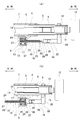
- FIG. 1 is a partial sectional view showing an electric position adjusting device for a steering wheel according to an example of an embodiment of the present invention.
- FIG. 2A is a view similar to FIG. 1 showing a state in which the steering wheel is located at the rear end of the front-rear position adjustment range
- FIG. FIG. 2 is a view similar to FIG.
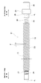
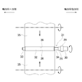
- FIG. 3 is a side view of a screw shaft according to an example of the embodiment of the present invention.
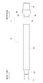
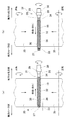
- FIG. 4 is a side view of a work as an intermediate material of the screw shaft according to an example of the embodiment of the present invention.
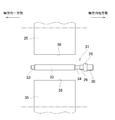
- FIG. 5 is a diagram showing a state in which a work is set on a rolling machine according to an example of an embodiment of the present invention.
- FIG. 1 is a partial sectional view showing an electric position adjusting device for a steering wheel according to an example of an embodiment of the present invention.
- FIG. 2A is a view similar to FIG. 1 showing a state in which the steering wheel is located at the rear end of the
- FIG. 6 shows an example of an embodiment of the present invention, in which the distance between a pair of rolling dies rotating in the normal rotation direction decreases with each other, and the rolling dies are attached to a large-diameter shaft portion for rolling a work. It is a figure which shows the state which pressed and started the rolling process.
- FIG. 7A shows an example of an embodiment of the present invention, in which a pair of rolling dies is rotated in the normal rotation direction in the middle of the rolling process, so that the workpiece is moved to one side in the axial direction.
- FIG. 7B shows a state in which the pair of rolling dies is rotated in the reverse direction in the middle of the rolling process, and the workpiece is moved to the other side in the axial direction.
- FIG. 7A shows an example of an embodiment of the present invention, in which a pair of rolling dies is rotated in the normal rotation direction in the middle of the rolling process, so that the workpiece is moved to one side in the axial direction.
- FIG. 7B shows a
- FIG. 4 is a diagram showing a state where the user has walked to the end of the circle.
- FIG. 8A shows an example of the embodiment of the present invention, in which the pair of rolling dies is rotated in the normal rotation direction at the final stage of the rolling process, so that the workpiece is moved to one side in the axial direction.
- FIG. 8B shows a state in which rolling marks are formed on the outer peripheral surface of the small diameter shaft portion for rolling on the other side in the axial direction of the workpiece while FIG. 8B shows the final stage of the rolling process.
- the pair of rolling dies rotate in the reverse direction, the work walks to the other end in the axial direction, and is formed on the outer peripheral surface of the small diameter shaft portion for rolling on one side in the axial direction of the work. It is a figure showing the state where a mark is formed.
- FIG. 9 is an enlarged view of a portion A in FIG.
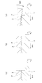
- FIGS. 10A to 10C are diagrams for explaining inconvenience caused by the conventional thread rolling.
- FIGS. 1 and 2 show an electric position adjusting device for a steering wheel using the screw shaft 21 (FIG. 3) of the present embodiment.
- the front-rear direction means the front-rear direction of the vehicle to which the device is assembled
- the front side is the left side of FIGS. 1 to 3
- the rear side is the FIGS. To the right.
- the electric position adjusting device for a steering wheel according to the present embodiment is capable of adjusting the front-rear position of the steering wheel 12 by using an electric motor (not shown) as a drive source.
- FIG. 1 shows a state in which the steering wheel 12 is located at an intermediate portion of the front / rear position adjustment range
- FIG. 2A shows a state in which the steering wheel 12 is located at the rear end of the front / rear position adjustment range
- FIG. 2B shows a state in which the steering wheel 12 is located at the front end of the front / rear position adjustment range.
- the electric position adjusting device for a steering wheel of the present invention can be constituted by the steering column 4, the steering shaft 5, and the electric actuator 6.
- the electric position adjusting device for a steering wheel according to the present invention includes at least an electric motor (not shown) and a feed screw mechanism 14 constituting the electric actuator 6, and an outer tube 10 constituting the steering shaft 5 and corresponding to a steering component.
- the steering column 4 includes a front outer column 7 and a rear inner column 8 which are combined with each other in a telescope shape.
- the outer column 7 is prevented from being displaced in the axial direction with respect to the vehicle body.
- the front side of the inner column 8 is slidably inserted into the inner diameter side of the rear side of the outer column 7.
- the steering shaft 5 includes a front inner shaft 9 and a rear outer tube 10.
- the inner shaft 9 and the outer tube 10 are combined so as to be able to transmit torque and extend and contract by spline engagement or the like.
- the inner shaft 9 is rotatably supported on the inner diameter side of the outer column 7 via a bearing (not shown).
- the outer tube 10 is rotatably supported on the inner diameter side of the inner column 8 via a bearing 11.
- the steering shaft 5 is rotatably supported on the inner diameter side of the steering column 4.
- the inner column 8 and the outer tube 10 can be axially displaced relative to the outer column 7 and the inner shaft 9.
- the steering wheel 12 is supported and fixed to a rear end of the outer tube 10 as a steering component.
- the electric actuator 6 includes a housing 13, a feed screw mechanism 14, and an electric motor (not shown).
- the housing 13 is supported and fixed to the lower surface of the outer column 7.
- the feed screw mechanism 14 includes a nut 15 and a rod 16.
- the center axis of the feed screw mechanism 14 is arranged parallel to the center axes of the steering shaft 5 and the steering column 4.
- the nut 15 has a female screw portion 17 on the inner peripheral surface.
- the nut 15 is rotatably supported in the housing 13 such that the nut 15 cannot be displaced in the axial direction and is rotatable, and is rotatable by an electric motor via a worm speed reducer 18.
- the rod 16 is configured by combining a screw shaft 21 arranged on the front side and an extension shaft 22 arranged on the rear side.
- the rear end of the extension shaft 22 constituting the rod 16 is connected to the rear side of the inner column 8 via the arm 20.
- the screw shaft 21 includes a large-diameter shaft portion 23, a first small-diameter shaft portion 24 and a second small-diameter shaft portion 25 corresponding to a small-diameter shaft portion, and a proximal shaft portion 26 corresponding to an adjacent shaft portion.
- the large-diameter shaft portion 23 has a male-side screw portion 19 screwed to the female-side screw portion 17 over the entire outer circumferential surface in the axial direction.
- the male screw portion 19 is formed by rolling.
- the axially intermediate portion of the male screw portion 19 except for both axial edge portions is constituted by a complete screw portion having a predetermined thread height.
- Each of both axial end portions of the male screw portion 19 is constituted by an incomplete screw portion less than a predetermined thread height.
- the entire male screw portion 19, including not only the complete screw portion but also the incomplete screw portion, is precisely finished so as to function as a normal screw portion.
- the flank surface of the male screw portion 19 is precisely finished not only at the axially intermediate portion, which is a complete screw portion, but also at both axial end edges, which are incomplete screw portions. For this reason, in this example, the axial length of the entire male screw portion 19 corresponds to the effective screw length.
- the flank surface is a side surface of the thread, that is, a tooth surface.
- the lead angle (lead angle) ⁇ of the male screw portion 19 is less than 4 °. However, when implementing the present invention, the lead angle ⁇ of the male screw portion 19 may be set to 4 ° or more.
- the first small diameter shaft portion 24 is disposed adjacent to one side in the axial direction, which is the front side of the large diameter shaft portion 23.
- the first small-diameter shaft portion 24 is a cylindrical portion having an outer diameter smaller than the outer diameter of the large-diameter shaft portion 23, and has a spiral first rolling trace 27 on the outer peripheral surface.
- the first rolling trace 27 is formed by a rolling die 35 for forming the male thread 19 in a rolling process.
- the first rolling trace 27 has the same phase as the extension of the spiral curve which is the groove bottom line of the male screw portion 19.
- the second small-diameter shaft portion 25 is disposed adjacent to the other side in the axial direction, which is the rear side of the large-diameter shaft portion 23.
- the second small-diameter shaft portion 25 is a cylindrical portion having an outer diameter smaller than the outer diameter of the large-diameter shaft portion 23, and has a spiral second rolling mark 28 on the outer peripheral surface.
- the second rolling trace 28 is formed by a rolling die 35 for forming the male thread 19 in the rolling process.
- the second rolling trace 28 has the same phase as the extension of the spiral curve which is the groove bottom line of the male screw portion 19.
- the outer diameter d 1 of the first small-diameter shaft portion 24, an outer diameter d 2 of the second small diameter shaft portion 25 can be made different from each other.
- the outer diameter d 1 of the first small-diameter shaft portion 24, and, each of the outer diameter d 2 of the second small diameter shaft portion 25, 0.9 times the groove bottom diameter D of the male screw portion 19 It is set in the range of not less than 1.1 times (the range of the difference from the groove bottom diameter D is ⁇ 10%) (1.1D ⁇ d 1 ⁇ 0.9D, 1.1D ⁇ d 2 ⁇ 0.9D). ).
- the range of the outer diameters d 1 and d 2 can be set to a range different from the range of the present example.
- each of the first rolling trace 27 and the second rolling trace 28 does not screw with the female thread 17 of the nut 15. That is, each of the first rolling trace 27 and the second rolling trace 28 corresponds to a non-threaded portion that does not function as a male threaded portion screwed with the female threaded portion 17 of the nut 15.
- the proximal shaft portion 26 is opposite to the large-diameter shaft portion 23 with respect to the second small-diameter shaft portion 25 in the axial direction, that is, on the other axial side that is the rear side of the second small-diameter shaft portion 25, They are located adjacent to each other.
- the proximal shaft portion 26 is a stepped columnar portion having an outer diameter larger than the outer diameter of the second small diameter shaft portion 25 as a whole.
- the proximal shaft portion 26 has a flange portion 29 protruding radially outward at an axially intermediate portion.
- a portion of the proximal shaft portion 26 located behind the flange portion 29 is configured by a columnar insertion portion 30.
- the extension shaft 22 is a hollow shaft having a circular tube shape.
- An insertion portion 30 of the screw shaft 21 is fixedly fitted to a front end of the extension shaft 22.
- the rear end surface of the flange portion 29 of the screw shaft 21 abuts on the front end surface of the extension shaft 22, whereby the screw shaft 21 is axially positioned with respect to the extension shaft 22.
- the rod 16 When adjusting the front-rear position of the steering wheel 12, the rod 16 is displaced in the axial direction with respect to the nut 15 by rotating the nut 15 via the worm speed reducer 18 by the electric motor. As the rod 16 is displaced in the axial direction, the inner column 8 connected to the rod 16 via the arm 20 and the outer tube 10 supported on the inner diameter side of the inner column 8 move in the same direction as the rod 16 (steering). (The position adjusting direction of the wheel 12), and the front-back position of the steering wheel 12 is adjusted. In this example, since the lead angle ⁇ of the male screw portion 19 is less than 4 °, even when an axial force is applied from the rod 16 to the nut 15 as a reverse input, the nut 15 is hard to rotate.
- the entire male screw portion 19 of the screw shaft 21 constituting the feed screw mechanism 14 is finished with high precision so as to function as a normal screw portion. Therefore, when the front-rear position of the steering wheel 12 is adjusted, the rod 16 is moved in the axial direction with respect to the nut 15 until the axial end edge of the male screw 19 is screwed with the female screw 17. Can be displaced. Further, the rod 16 can be displaced in the axial direction with respect to the nut 15 until a part in the axial direction of the female screw portion 17 reaches an axial position deviated from the male screw portion 19.
- both ends in the axial direction of the male thread are not fed as compared with a conventional product that cannot function as a normal thread.
- the operation stroke of the screw mechanism 14 can be lengthened, that is, the adjustment range of the front and rear positions of the steering wheel 12 can be widened.
- the operation stroke of the feed screw mechanism 14 is determined to be a predetermined length, compared to a conventional product in which both ends in the axial direction of the male screw portion cannot function as a normal screw portion.
- the axial dimension of the feed screw mechanism 14 can be reduced.
- the rod 16 can be displaced in the axial direction with respect to the nut 15 until a part of the female thread 17 in the axial direction reaches an axial position deviated from the male thread 19. ing. Accordingly, the effect of increasing the adjustment range of the front-rear position of the steering wheel 12 and the effect of reducing the axial dimension of the feed screw mechanism 14 can be further enhanced.
- the axial length La of a part of the female screw portion in the axial direction is a maximum, and the axial length of the screw portion of the female screw portion and the male screw portion in this state is maximum. It can be about 70% of Lb (La (0.7 Lb).
- the first rolling The imprint mark 27 and the second rolling mark 28 can function as a grease reservoir for lubrication of the feed screw mechanism 14.
- the steering wheel 12 when the steering wheel 12 is moved to the front end of the position adjustment range, the steering wheel 12 is fixed to the rear end of the housing 13 and is disposed around the screw shaft 21.
- the rear surface of the formed annular contact member 37 is configured to contact the front surface of the flange portion 29 of the proximal shaft portion 26. Therefore, the steering wheel 12 is prevented from moving further forward. That is, the flange portion 29 functions as a stopper that defines the front end of the position adjustment range of the steering wheel 12.
- the method for manufacturing a position adjusting device for a steering wheel includes an electric motor (not shown), a feed screw mechanism 14, and an outer tube 10 as a steering component.
- the screw shaft 21 and the nut 15 are configured to be relatively displaceable in the axial direction based on the relative rotation of the nut and the nut 15, whereby the outer tube 10 is displaceable in the position adjustment direction of the steering wheel 12.
- the present invention relates to a method for manufacturing a steering wheel electric position adjusting device.
- the method for manufacturing a position adjusting device for a steering wheel includes a rolling large-diameter shaft portion 32 and a rolling large-diameter shaft portion 32 which are disposed adjacent to each other in the axial direction of the rolling large-diameter shaft portion 32.
- the workpiece 31 provided with the first small diameter shaft portion 33 for rolling and the second small diameter shaft portion 34 for rolling having an outer diameter smaller than the outer diameter of the large diameter shaft portion 32 for rolling.
- a process of manufacturing the screw shaft 21 by performing a rolling process in which the work 31 has a step using a plurality of rolling dies 35 is performed. Prepare.
- the axial direction means the axial direction of the work 31 which is an intermediate material of the screw shaft 21 unless otherwise specified.
- One axial side is the left side of FIGS. The other side is the right side of FIGS.
- FIG. 4 shows the work 31.
- the work 31 has a shape other than the male screw portion 19, the first rolling trace 27, and the second rolling trace 28 in the screw shaft 21 (see FIG. 3). That is, the workpiece 31 has a large-diameter shaft portion 32 for rolling in which the male screw portion 19 is formed on the outer peripheral surface, and a first small-diameter shaft for rolling in which the first rolling mark 27 is formed on the outer peripheral surface. A portion 33, a second small diameter shaft portion 34 for rolling in which the second rolling mark 28 is formed on the outer peripheral surface, and a proximal shaft portion 26.
- the outer peripheral surface of the rolled large-diameter shaft portion 32 is a cylindrical surface whose outer diameter does not change in the axial direction, except for the chamfered portions formed at both ends in the axial direction.
- the first small diameter shaft portion 33 for rolling is disposed adjacent to one side in the axial direction of the large diameter shaft portion 32 for rolling, and has an outer diameter smaller than the outer diameter of the large diameter shaft portion 32 for rolling.
- the second small diameter shaft portion 34 for rolling is disposed adjacent to the other side in the axial direction of the large diameter shaft portion 32 for rolling, and has an outer diameter smaller than the outer diameter of the large diameter shaft portion 32 for rolling. Having.
- the outer diameter of the first small diameter shaft portion 33 for rolling is d 1 like the outer diameter of the first small diameter shaft portion 24 (see FIG. 3), and the outer diameter of the second small diameter shaft portion 34 for rolling.
- the outer diameter is d 2 , like the outer diameter of the second small diameter shaft portion 25 (see FIG. 3).
- the rolling machine includes a pair of rolling dies 35.
- Each of the rolling dies 35 is a round die having a short columnar shape, and is arranged in parallel with each other with the outer peripheral surfaces thereof facing each other.
- Each of the rolling dies 35 has a spiral rolling tooth 36 (see FIG. 9, and the shape is not shown in FIGS. 5 to 8) for rolling the male screw portion 19 on the outer peripheral surface.
- the axial dimension of the rolling die 35 is substantially equal to the axial dimension of the large diameter shaft portion 32 for rolling of the work 31.
- the axial dimension of the rolling die 35 can be larger or smaller than the axial dimension of the large-diameter shaft portion 32 for rolling.
- the interval between the outer peripheral surfaces of the pair of rolling dies 35 is sufficiently larger than the outer diameter of the large diameter shaft portion 32 for rolling of the work 31. It is getting bigger.
- the work 31 With the work 31 set on the rolling machine, the work 31 is arranged at a central position between the outer peripheral surfaces of the pair of rolling dies 35 in parallel with the pair of rolling dies 35. Each outer peripheral surface of the rolling die 35 faces the outer peripheral surface of the large diameter shaft portion 32 for rolling of the work 31.
- the work 31 is sandwiched from both sides in the axial direction by a pair of centers provided in a work support device (not shown) constituting the rolling machine.
- the work 31 is rotatably supported by the work support device and freely movable in the axial direction with respect to the pair of rolling dies 35.
- the work supporting apparatus allows the work 31 to expand even when the work 31 elongates due to the rolling process of the work 31 by expanding the interval between the pair of centers.
- the work 31 is subjected to an axial clamping force from the pair of centers.
- the portion of the work 31 located on the other axial side of the large-diameter shaft portion 32 for rolling is constituted by the second small-diameter shaft portion 34 for rolling and the proximal-side shaft portion 26.
- the outer diameter of the proximal shaft section 26 is larger than the outer diameter of the second small diameter shaft section 34 for rolling. For this reason, in the case of the work 31 of the present example, the outer diameter of the portion corresponding to the proximal shaft portion 26 is equal to the outer diameter of the second small-diameter shaft portion 34 for rolling.
- the rigidity of the portion located on the other side in the axial direction from the large-diameter shaft portion 32 for rolling is higher. For this reason, when the pinching force in the axial direction is applied from the pair of centers, the portion located on the other side in the axial direction from the large-diameter shaft portion 32 for rolling is effectively prevented from buckling.
- incision is started, which is a step of cutting the outer peripheral surfaces (rolling teeth 36) of the pair of rolling dies 35 into the outer peripheral surface of the large-diameter shaft portion 32 for rolling of the work 31. Is done.
- the cutting is started, the work 31 is given a rotational force from the pair of rolling dies 35 and rotates in the opposite direction to the pair of rolling dies 35.
- the entire periphery of the outer peripheral surface of the large-diameter shaft portion 32 for rolling of the work 31 is subjected to the rolling process, and the male screw portion 19 is gradually formed.
- the pair of rolling dies 35 alternately repeat the rotation in the forward rotation direction, which is the rotation direction at the start of the cutting, and the reverse rotation direction, which is the opposite direction, by the NC control. .
- the work 31 is subjected to the rolling process while reciprocating in the axial direction between the outer peripheral surfaces of the pair of rolling dies 35.
- the pair of rolling dies 35 rotates in the normal rotation direction
- the work 31 moves to the other side in the axial direction as shown in FIG.
- 35 rotates in the reverse direction it moves to one side in the axial direction as shown in FIG.
- the rolling of the work 31 is performed while the movement of the work 31 to the other side in the axial direction and the movement to the one side in the axial direction are alternately repeated.
- the NC control is configured so that the movement of the workpiece 31 to the other side in the axial direction stops at the axial position shown in FIG.
- the axial position shown in FIG. 7A is the axial position at which the entire first small diameter shaft portion 33 for rolling of the work 31 has entered between the outer peripheral surfaces of the pair of rolling dies 35. It is.
- the movement of the workpiece 31 to one side in the axial direction stops at the axial position shown in FIG. 7B.
- the portion of the second small diameter shaft portion 34 of the work 31 except for the end on the other side in the axial direction is the outer peripheral surface of the pair of rolling dies 35. This is the axial position at which the movement has been completed. Therefore, in this example, the rolling process is performed without each of the pair of rolling dies 35 hitting the base shaft portion 26 of the work 31.
- the cutting step includes, as shown in FIGS. 8A and 9, the male thread 19 on the outer peripheral surface of the large-diameter shaft portion 32 by a pair of rolling dies 35.
- a spiral first rolling mark 27 is formed on the outer peripheral surface of the first small diameter shaft portion 33 for rolling
- FIG. 5 the rolling process for forming the male screw portion 19 on the outer peripheral surface of the large-diameter shaft portion 32 for rolling is performed by the pair of rolling dies 35, and at the same time, the second process is performed. The process is performed until the spiral second rolling mark 28 is formed on the outer peripheral surface of the small diameter shaft portion 34 for rolling.
- each of the first rolling trace 27 and the second rolling trace 28 is The spiral trace has the same phase as the extension of the spiral curve which is the groove bottom line of the screw portion 19.
- each of the first rolling trace 27 and the second rolling trace 28 is a spiral trace formed integrally with the male screw portion 19.
- the outer diameter d 1 of the first rolling small-diameter shaft portion 33, and the outer diameter d 2 of the second rolling small-diameter shaft portion 34, the groove bottom diameter D of the male screw portion 19 When the first rolling trace 27 and the second rolling trace 28 are also somewhat smaller, the male thread portion 19 may be discontinuous with each of the first rolling trace 27 and the second rolling trace 28.
- the flank surface of the male screw portion 19 is formed not only at the axial middle portion which is a complete screw portion, but also at both axial end edges which are an incomplete screw portion. Can be finished precisely.
- the outer peripheral surfaces of the pair of rolling dies 35 form the workpiece 31.
- the rolling process for forming the male screw portion 19 is performed in a state of being in contact with only the outer peripheral surface of the large-diameter shaft portion 32 for use.
- one end in the axial direction of the outer peripheral surface of the pair of rolling dies 35 is formed on the outer periphery of the large-diameter shaft portion 32 for rolling due to the steps that occur in the work 31.
- FIG. 7A one end in the axial direction of the outer peripheral surface of the pair of rolling dies 35 is formed on the outer periphery of the large-diameter shaft portion 32 for rolling due to the steps that occur in the work 31.
- the other end in the axial direction of the outer peripheral surface of the pair of rolling dies 35 has a large diameter for rolling due to the case where the outer peripheral surface of the pair of rolling dies 35 is displaced in the axial direction from the surface.
- a large change occurs in the distribution of the rolling load applied between the pair of rolling dies 35 and the work 31.
- the amount of elastic deformation of the rolling machine supporting the pair of rolling dies 35 and the work 31 is changed by an amount corresponding to the change, so that the distance between the pair of rolling dies 35 and the work 31 is increased.
- Tends to cause relative displacement such as inclination.
- the processing accuracy of the both ends in the axial direction of the male screw portion 19 during the processing becomes low.
- the outer peripheral surfaces of the pair of rolling dies 35 are only the outer peripheral surfaces of the large diameter shaft portion 32 for rolling. Instead, it comes into contact with the outer peripheral surfaces of the first small diameter shaft portion 33 for rolling and the second small diameter shaft portion 34 for rolling.
- one end in the axial direction of the outer peripheral surface of the pair of rolling dies 35 is formed on the outer periphery of the large-diameter shaft portion 32 for rolling, due to a step occurring in the work 31.
- the outer peripheral surface of the pair of rolling dies 35 When the outer peripheral surface of the pair of rolling dies 35 is deviated in the axial direction from the surface, one end in the axial direction of the outer peripheral surface of the pair of rolling dies 35 is in contact with and supported by the outer peripheral surface of the first small diameter shaft portion 33 for rolling. A large change in the distribution of the rolling load acting between the pair of rolling dies 35 and the work 31 can be prevented. As shown in FIG. 8B, the other end in the axial direction of the outer peripheral surface of the pair of rolling dies 35 extends in the axial direction from the outer peripheral surface of the large-diameter shaft portion 32 for rolling due to the step that occurs in the work 31.
- the other axial end of the outer peripheral surface of the pair of rolling dies 35 is in contact with and supported by the outer peripheral surface of the second small-diameter shaft portion 34 for rolling.
- a large change in the distribution of the rolling load acting between the forming die 35 and the work 31 can be prevented. Therefore, in the final stage of the cutting process, a change in the amount of elastic deformation of the rolling machine supporting the pair of the rolling dies 35 and the work 31 can be suppressed. For this reason, relative displacement such as inclination between the pair of rolling dies 35 and the work 31 can be suppressed.
- the male screw portion 19 is a so-called triangular screw of a metric coarse thread, and at the final stage of the cutting step, as shown in FIGS. 8 and 9, a pair of rolling dies 35.
- the contact area between the pair of rolling dies 35 and the work 31 is increased by increasing the cut amount to such an extent that the meat of the work 31 (the top of the male screw portion 19) is in contact with the groove bottom of the rolling tooth 36 of FIG. Become. Therefore, this also makes it difficult to cause relative displacement such as the inclination in the final stage of the cutting step.
- the flank surface of the male screw portion 19 can be precisely finished not only at the axially intermediate portion, which is a complete screw portion, but also at both axial end edges, which are incomplete screw portions.
- a method of double rolling which is a method of performing the rolling process on the work 31 in two times, can also be adopted.
- relative displacement such as the inclination can be made harder to occur in the final stage of the cutting process.
- the outer diameter d 1 of the first small-diameter shaft portion 33 for rolling and the outer diameter of the second small-diameter shaft portion 34 for rolling are larger than the groove bottom diameter D of the male screw portion 19.
- d 2 is increased, as the outer diameters d 1 and d 2 increase, the axial end of the rolling tooth 36 of the rolling die 35 becomes larger in the final stage of the cutting process. The resistance when climbing from the radial shaft portion 32 to the first rolling small-diameter shaft portion 33 and the second rolling small-diameter shaft portion 34 is increased.
- a not-shown chamfered portion such as a C-chamfered portion or an R-chamfered portion exists at the axial edge portion of the rolled tooth 36.
- the chamfering is performed. The portion pushes the meat of the first small diameter shaft portion 33 for rolling and the second small diameter shaft portion 34 for rolling in the axial direction.
- the resistance to pushing the meat in the axial direction is large.
- the amount by which the chamfered portion pushes the meat in the axial direction increases as the outer diameters d 1 and d 2 increase. For this reason, the resistance increases as the outer diameters d 1 and d 2 increase. If the resistance becomes excessive, excessive elongation or twisting occurs in the work 31, which adversely affects the processing accuracy of the male screw portion 19.
- the outer diameter d 1 of the first small-diameter shaft portion 33 and the second rolling diameter are smaller than the groove bottom diameter D of the male screw portion 19.
- the outer diameter d 2 of the small-diameter shaft portion 34 is increased, the outer diameters d 1 and d 2 are set to 1.1 times or less of the groove bottom diameter D of the male screw portion 19 (the groove bottom diameter D is It is set so as to be + 10% or less as a reference (1.1D ⁇ d 1 > D, 1.1D ⁇ d 2 > D).
- the outer diameter d 1 of the first small-diameter shaft portion 33 and the second rolling diameter are smaller than the groove bottom diameter D of the male screw portion 19.
- the outer diameters d 1 and d 2 are set to 0.9 times or more of the groove bottom diameter D of the male screw portion 19 (the groove bottom diameter D is (D> d 1 ⁇ 0.9D, D> d 2 ⁇ 0.9D).
- the number of threads of the male screw portion 19 of the screw shaft 21 to be manufactured is not particularly limited.
- the male screw portion 19 may be a double-thread in addition to a single-thread as shown.
- the load balance when performing the rolling process becomes better than when the male screw portion 19 is a single screw.
- the axial range forming the first rolling trace 27 and the second rolling trace 28 and the circumferential length of the first rolling trace 27 and the second rolling trace 28 can be set to any value.
- the axial length of the axial range forming the first rolling trace 27 and the second rolling trace 28 is about 0.02 to 2.5 times the lead of the male screw portion 19 (for example, 1.0 to 1.5 times).
- the second small-diameter shaft portion 25 has a second rolling end at the other axial end. There is a portion where no mark 28 is formed.
- the entirety of the portion located on the other side in the axial direction from the portion where the second rolling trace 28 is formed may be used as the proximal shaft portion 26.
- the rotation direction of the pair of rolling dies is not reversed, and the rotation direction is set to a predetermined direction. May be adopted.
- the cutting step can be started from the axial position shown in FIG. 8B and ended at the axial position shown in FIG. 8A.
- the rolling method of the screw shaft in the present invention is, for example, a through-feed rolling method described in JP-A-2003-33841 or the like, as long as the rolling method causes a step in the work during the rolling process.
- a flat plate rolling method or the like can be adopted.
- a pair of rolling dies round dies whose central axes are inclined to each other are used in order to cause a step in the work.
- the work is supplied from the axial direction between the pair of rolling dies while rotating the pair of rolling dies in the same direction while keeping the interval between the pair of rolling dies constant. While the work passes in the axial direction by a step between a pair of rolling dies, the work is subjected to a rolling process.
- a pair of rolling dies is used to form a male thread on the outer peripheral surface of the large-diameter shaft portion for rolling, and at the same time, the first rolling is performed.
- the work since the work passes in the axial direction between a pair of rolling dies, the work is provided on the first rolling small diameter shaft portion on one side in the axial direction with respect to the first rolling small diameter shaft portion. It does not have a portion whose outer diameter is larger than the small diameter shaft portion for forming, and is located on the other side in the axial direction of the second small diameter shaft portion for rolling, and is located outside the second small diameter shaft portion for rolling. It is preferable to use a work having no portion having a large diameter. However, for example, like the work 31 of the embodiment, the outer diameter of the second small diameter shaft portion 34 is smaller on the other side in the axial direction than the second small diameter shaft portion 34.
- the axial dimension L of the second small-diameter shaft portion 34 for rolling is sufficiently larger than the axial dimension of each of the pair of rolling dies.
- a pair of rolling dies each having a flat plate shape is used.
- the pair of rolling dies face each other and have rolling teeth on the side surfaces.
- the work is supplied between the side surfaces while the pair of rolling dies is relatively moved in parallel to the side surfaces facing each other.
- the work is subjected to a rolling process while giving a step to the work.
- a pair of rolling dies is used to form a male thread on the outer peripheral surface of the large-diameter shaft portion for rolling, and at the same time, the first rolling is performed.
- the work 1 of the embodiment is subjected to the rolling process by the flat plate rolling method, for example, the work 1 is rolled from the positional relationship between the work 31 and a pair of rolling dies shown in FIG.
- the forming process is started, and the rolling process can be completed based on the positional relationship between the work 31 and the pair of rolling dies shown in FIG.
- the number of rolling dies used for rolling may be three or more.
- the present invention is applicable not only to the screw shaft constituting the sliding screw type feed screw mechanism, but also to the screw shaft constituting the ball screw type feed screw mechanism.
- the male screw portion of the screw shaft becomes a male screw groove.
- each of the first rolling trace and the second rolling trace forming the screw shaft is a plurality of rolling traces. It is not used as a male thread for engaging the ball.
- An electric position adjusting device for a steering wheel according to the present invention is disclosed in JP-A-2005-199760, JP-A-2006-32484, JP-A-2015-227166 and the like, and has various structures conventionally known.
- the present invention is applicable to a device (a device capable of adjusting at least one of a front-rear position and a vertical position of a steering wheel).
- the feed screw mechanism having the screw shaft of the present invention is not limited to an electric position adjusting device for a steering wheel, but is incorporated in various mechanical devices such as an electric steering wheel of a car, an electric storage device of a headlight, and a table moving device of a machine tool. Can be used.
Landscapes
- Engineering & Computer Science (AREA)
- Mechanical Engineering (AREA)
- General Engineering & Computer Science (AREA)
- Chemical & Material Sciences (AREA)
- Combustion & Propulsion (AREA)
- Transportation (AREA)
- Transmission Devices (AREA)
- Power Steering Mechanism (AREA)
- Printing Plates And Materials Therefor (AREA)
- Steering Controls (AREA)
Abstract
Description
前記大径軸部は、外周面に軸方向全長にわたり雄側ねじ部を有する。
前記小径軸部は、前記大径軸部の軸方向に隣接して配置され、該大径軸部の外径よりも小さい外径を有し、かつ、外周面に、前記雄側ねじ部の溝底線である螺旋曲線の延長線と同位相となる螺旋状の転造痕を有する。
転造用大径軸部と、該転造用大径軸部の軸方向一方側に配置され、前記転造用大径軸部の外径よりも小さい外径を有する第1の転造用小径軸部と、前記転造用大径軸部の軸方向他方側に配置され、前記転造用大径軸部の外径よりも小さい外径を有する第2の転造用小径軸部と、を備えたワークに対し、前記転造用大径軸部の外周面に軸方向全長にわたり雄側ねじ部を形成するために、複数個の転造ダイスを用いて前記ワークに歩みが生じる転造加工を施す工程により、ねじ軸を製造する工程を備える。
本発明の実施の形態の1例について、図1~図9を用いて説明する。
図1および図2は、本例のねじ軸21(図3)を用いたステアリングホイールの電動位置調節装置を示している。なお、ステアリングホイールの電動位置調節装置に関して、前後方向は、該装置が組み付けられる車両の前後方向を意味し、前側は、図1~図3の左側であり、後側は、図1~図3の右側である。また、本例のステアリングホイールの電動位置調節装置は、図示しない電動モータを駆動源として、ステアリングホイール12の前後位置調節を可能としている。図1は、ステアリングホイール12が前後位置調節範囲の中間部に位置する状態を示しており、図2(a)は、ステアリングホイール12が前後位置調節範囲の後端部に位置する状態を示しており、図2(b)は、ステアリングホイール12が前後位置調節範囲の前端部に位置する状態を示している。
本発明のステアリングホイールの位置調節装置の製造方法は、電動モータ(図示せず)と、送りねじ機構14と、操舵部品であるアウタチューブ10とを備え、送りねじ機構14が、外周面に雄側ねじ部19を有するねじ軸21と、雄側ねじ部19に対して係合する雌側ねじ部17を内周面に有するナット15とを備え、前記電動モータから伝わる回転力によりねじ軸21とナット15とが相対回転することに基づいて、ねじ軸21とナット15とが軸方向に相対変位可能に構成されており、これにより、アウタチューブ10がステアリングホイール12の位置調節方向に変位可能となっている、ステアリングホイールの電動位置調節装置の製造方法に関する。
2 転造ダイス
3 雄側ねじ部
4 ステアリングコラム
5 ステアリングシャフト
6 電動アクチュエータ
7 アウタコラム
8 インナコラム
9 インナシャフト
10 アウタチューブ
11 軸受
12 ステアリングホイール
13 ハウジング
14 送りねじ機構
15 ナット
16 ロッド
17 雌側ねじ部
18 ウォーム減速機
19 雄側ねじ部
20 腕部
21 ねじ軸
22 延長軸
23 大径軸部
24 第1の小径軸部
25 第2の小径軸部
26 基端側軸部
27 第1の転造痕
28 第2の転造痕
29 フランジ部
30 挿入部
31 ワーク
32 転造用大径軸部
33 第1の転造用小径軸部
34 第2の転造用小径軸部
35 転造ダイス
36 転造歯
37 当接部材
Claims (15)
- 大径軸部と、小径軸部とを備え、
前記大径軸部は、外周面に軸方向全長にわたり雄側ねじ部を有し、
前記小径軸部は、前記大径軸部の軸方向に隣接して配置され、該大径軸部の外径よりも小さい外径を有し、かつ、外周面に、前記雄側ねじ部の溝底線である螺旋曲線の延長線と同位相となる螺旋状の転造痕を有する、
ねじ軸。 - 前記小径軸部の外径は、前記雄側ねじ部の溝底径の0.9倍以上1.1倍以下である、請求項1に記載のねじ軸。
- 前記小径軸部に対し、軸方向に関して前記大径軸部と反対側に隣接して配置され、該小径軸部の外径よりも大きい外径を有する隣接軸部を備える、請求項1または2に記載のねじ軸。
- 前記小径軸部は、前記大径軸部の軸方向一方側に配置される第1の小径軸部と、前記大径軸部の軸方向他方側に配置される第2の小径軸部とにより構成される、請求項1~3のいずれかに記載のねじ軸。
- 第1の小径軸部の外径および第2の小径軸部の外径はいずれも、前記雄側ねじ部の溝底径の0.9倍以上1.1倍以下である、請求項4に記載のねじ軸。
- ステアリングホイールの電動位置調節装置に組み込まれることができる、請求項4または5に記載のねじ軸。
- 転造用大径軸部と、前記転造用大径軸部の軸方向に隣接して配置され、前記転造用大径軸部の外径よりも小さい外径を有する転造用小径軸部と、を備えたワークに対し、前記転造用大径軸部の外周面に軸方向全長にわたり雄側ねじ部を形成するために、複数個の転造ダイスを用いて前記ワークに歩みが生じる転造加工を施す工程を備え、
前記ワークに対し前記転造加工を施す工程において、前記転造ダイスにより、前記転造用大径軸部の外周面に雄側ねじ部を形成するための転造加工を施すのと同時に、前記転造用小径軸部の外周面に螺旋状の転造痕を形成する、
ねじ軸の製造方法。 - 前記転造用小径軸部の外径を、前記転造用大径軸部の外周面に形成すべき雄側ねじ部の溝底径の0.9倍以上1.1倍以下とする、請求項7に記載のねじ軸の製造方法。
- 前記ワークとして、前記転造用小径軸部に対し、軸方向に関して前記転造用大径軸部と反対側に隣接して配置され、該転造用小径軸部の外径よりも大きい外径を有する隣接軸部を備えたワークを用いる、請求項7または8に記載のねじ軸の製造方法。
- 前記ワークとして、前記転造用小径軸部が、前記転造用大径軸部の軸方向一方側に配置される第1の転造用小径軸部と、前記転造用大径軸部の軸方向他方側に配置される第2の転造用小径軸部とにより構成されたワークを用いる、請求項7~9のいずれかに記載のねじ軸の製造方法。
- 第1の小径軸部の外径および第2の小径軸部の外径をいずれも、前記雄側ねじ部の溝底径の0.9倍以上1.1倍以下とする、請求項10に記載のねじ軸の製造方法。
- 前記ねじ軸として、ステアリングホイールの電動位置調節装置に組み込まれるねじ軸を適用する、請求項10または11に記載のねじ軸の製造方法。
- 電動モータと、送りねじ機構と、操舵部品とを備え、
前記送りねじ機構は、外周面に雄側ねじ部を有するねじ軸と、前記雄側ねじ部に対して係合する雌側ねじ部を内周面に有するナットとを備え、前記電動モータから伝わる回転力により前記ねじ軸と前記ナットとが相対回転することに基づいて、前記ねじ軸と前記ナットとが軸方向に相対変位可能に構成されており、
前記操舵部品は、使用状態でステアリングホイールが固定され、前記ねじ軸と前記ナットとが軸方向に相対変位することに伴って、前記ステアリングホイールの位置調節方向に変位可能であり、
前記ねじ軸が、請求項6に記載されているねじ軸により構成されている、
ステアリングホイールの電動位置調節装置。 - 前記ステアリングホイールを位置調節範囲の端部まで変位させた状態で、前記雌側ねじ部の軸方向一部が、前記雄側ねじ部から外れた軸方向位置に配置可能である、請求項13に記載のステアリングホイールの電動位置調節装置。
- 電動モータと、送りねじ機構と、操舵部品とを備え、前記送りねじ機構が、外周面に雄側ねじ部を有するねじ軸と、前記雄側ねじ部に対して係合する雌側ねじ部を内周面に有するナットとを備え、前記電動モータから伝わる回転力により前記ねじ軸と前記ナットとが相対回転することに基づいて、前記ねじ軸と前記ナットとが軸方向に相対変位可能に構成されている、ステアリングホイールの電動位置調節装置の製造方法であって、
転造用大径軸部と、該転造用大径軸部の軸方向一方側に配置され、前記転造用大径軸部の外径よりも小さい外径を有する第1の転造用小径軸部と、前記転造用大径軸部の軸方向他方側に配置され、前記転造用大径軸部の外径よりも小さい外径を有する第2の転造用小径軸部と、を備えたワークに対し、前記転造用大径軸部の外周面に軸方向全長にわたり雄側ねじ部を形成するために、複数個の転造ダイスを用いて前記ワークに歩みが生じる転造加工を施す工程により、ねじ軸を製造する工程を備え、
前記ねじ軸を製造する工程において、請求項12に記載のねじ軸の製造方法を採用する、
ステアリングホイールの電動位置調節装置の製造方法。
Priority Applications (4)
| Application Number | Priority Date | Filing Date | Title |
|---|---|---|---|
| DE112019004027.8T DE112019004027B4 (de) | 2018-08-10 | 2019-07-17 | Gewindewelle und Verfahren zur Fertigung dieser und elektrische Positionseinstellvorrichtung für ein Lenkrad und Verfahren zur Fertigung dieser |
| CN201980053134.0A CN112566736B (zh) | 2018-08-10 | 2019-07-17 | 丝杠轴及其制造方法、进给丝杠机构和方向盘的电动位置调节装置及其制造方法 |
| US17/267,266 US12043302B2 (en) | 2018-08-10 | 2019-07-17 | Screw shaft and method for manufacturing same, and electric position adjusting device for steering wheel and method for manufacturing same |
| JP2020536412A JP7115547B2 (ja) | 2018-08-10 | 2019-07-17 | ねじ軸およびその製造方法、並びに、ステアリングホイールの電動位置調節装置およびその製造方法 |
Applications Claiming Priority (4)
| Application Number | Priority Date | Filing Date | Title |
|---|---|---|---|
| JP2018151671 | 2018-08-10 | ||
| JP2018-151671 | 2018-08-10 | ||
| JP2018235095 | 2018-12-17 | ||
| JP2018-235095 | 2018-12-17 |
Publications (1)
| Publication Number | Publication Date |
|---|---|
| WO2020031637A1 true WO2020031637A1 (ja) | 2020-02-13 |
Family
ID=69413451
Family Applications (1)
| Application Number | Title | Priority Date | Filing Date |
|---|---|---|---|
| PCT/JP2019/028104 Ceased WO2020031637A1 (ja) | 2018-08-10 | 2019-07-17 | ねじ軸およびその製造方法、並びに、ステアリングホイールの電動位置調節装置およびその製造方法 |
Country Status (5)
| Country | Link |
|---|---|
| US (1) | US12043302B2 (ja) |
| JP (1) | JP7115547B2 (ja) |
| CN (1) | CN112566736B (ja) |
| DE (1) | DE112019004027B4 (ja) |
| WO (1) | WO2020031637A1 (ja) |
Cited By (4)
| Publication number | Priority date | Publication date | Assignee | Title |
|---|---|---|---|---|
| WO2022080331A1 (ja) * | 2020-10-13 | 2022-04-21 | 日本精工株式会社 | ねじ軸およびその製造方法、並びに、ステアリングホイールの電動位置調節装置 |
| JP2023022878A (ja) * | 2021-08-04 | 2023-02-16 | 日本精工株式会社 | ボールねじ装置 |
| US20230264732A1 (en) * | 2022-02-22 | 2023-08-24 | Thyssenkrupp Presta Ag | Adjustment drive for a steering column and steering column for a motor vehicle |
| TWI906068B (zh) * | 2024-12-05 | 2025-11-21 | 鍵財機械企業股份有限公司 | 自動傳動裝置 |
Families Citing this family (2)
| Publication number | Priority date | Publication date | Assignee | Title |
|---|---|---|---|---|
| JP7235182B1 (ja) * | 2021-04-15 | 2023-03-08 | 日本精工株式会社 | ボールねじ装置およびその製造方法 |
| BE1030168B1 (de) * | 2022-07-26 | 2023-08-01 | Thyssenkrupp Ag | Lenksäule für ein Kraftfahrzeug und Verfahren zur Herstellung einer elektrisch verstellbaren Lenksäule |
Citations (5)
| Publication number | Priority date | Publication date | Assignee | Title |
|---|---|---|---|---|
| JPH09225573A (ja) * | 1996-02-23 | 1997-09-02 | Ntn Corp | 転造ボールねじ用素材棒及びそれを用いた転造ボールねじの製造方法 |
| JP2003033841A (ja) * | 2001-07-18 | 2003-02-04 | Nsk Ltd | ボールねじのねじ軸の製造方法 |
| JP2008281142A (ja) * | 2007-05-11 | 2008-11-20 | Nsk Ltd | ボールねじ機構のねじ軸及びねじ軸の製造方法 |
| JP2010208440A (ja) * | 2009-03-09 | 2010-09-24 | Honda Motor Co Ltd | 操舵装置 |
| JP2015227166A (ja) * | 2012-05-25 | 2015-12-17 | 日本精工株式会社 | 電動ステアリングホイールの位置調節装置 |
Family Cites Families (13)
| Publication number | Priority date | Publication date | Assignee | Title |
|---|---|---|---|---|
| US6149363A (en) * | 1998-10-29 | 2000-11-21 | Huck International, Inc. | Lightweight threaded fastener and thread rolling die |
| JP4245009B2 (ja) * | 1998-12-25 | 2009-03-25 | 日本精工株式会社 | 電動位置調整式ステアリングコラム装置 |
| JP3828389B2 (ja) * | 2001-07-23 | 2006-10-04 | 新家工業株式会社 | 隔壁を有する管の製造方法、製造装置及びその製品 |
| JP4333372B2 (ja) * | 2004-01-13 | 2009-09-16 | 日本精工株式会社 | チルト位置調整式ステアリングコラム装置 |
| JP4438426B2 (ja) * | 2004-01-26 | 2010-03-24 | セイコーエプソン株式会社 | 投写用スクリーン |
| JP4888760B2 (ja) * | 2005-10-20 | 2012-02-29 | 日本精工株式会社 | ねじ軸形成方法及びボールねじ機構のねじ軸 |
| JP2011183415A (ja) * | 2010-03-05 | 2011-09-22 | Sanyo Electric Co Ltd | リードスクリューの製造方法 |
| JP5957716B2 (ja) * | 2012-06-01 | 2016-07-27 | 株式会社青山製作所 | 焼付き防止ボルト |
| WO2015012330A1 (ja) * | 2013-07-23 | 2015-01-29 | 株式会社ニッセー | 転造機とこの転造機を用いた歯車の転造方法 |
| JP6202188B2 (ja) * | 2014-02-25 | 2017-09-27 | 日本精工株式会社 | ボールねじ装置 |
| JP6673540B2 (ja) * | 2018-01-19 | 2020-03-25 | 日本精工株式会社 | ナット、送りねじ機構およびステアリングホイールの電動位置調節装置 |
| JP7109216B2 (ja) | 2018-03-12 | 2022-07-29 | 日立Astemo株式会社 | ステアリング装置の転舵軸の製造方法 |
| WO2022080331A1 (ja) * | 2020-10-13 | 2022-04-21 | 日本精工株式会社 | ねじ軸およびその製造方法、並びに、ステアリングホイールの電動位置調節装置 |
-
2019
- 2019-07-17 WO PCT/JP2019/028104 patent/WO2020031637A1/ja not_active Ceased
- 2019-07-17 US US17/267,266 patent/US12043302B2/en active Active
- 2019-07-17 JP JP2020536412A patent/JP7115547B2/ja active Active
- 2019-07-17 DE DE112019004027.8T patent/DE112019004027B4/de active Active
- 2019-07-17 CN CN201980053134.0A patent/CN112566736B/zh active Active
Patent Citations (5)
| Publication number | Priority date | Publication date | Assignee | Title |
|---|---|---|---|---|
| JPH09225573A (ja) * | 1996-02-23 | 1997-09-02 | Ntn Corp | 転造ボールねじ用素材棒及びそれを用いた転造ボールねじの製造方法 |
| JP2003033841A (ja) * | 2001-07-18 | 2003-02-04 | Nsk Ltd | ボールねじのねじ軸の製造方法 |
| JP2008281142A (ja) * | 2007-05-11 | 2008-11-20 | Nsk Ltd | ボールねじ機構のねじ軸及びねじ軸の製造方法 |
| JP2010208440A (ja) * | 2009-03-09 | 2010-09-24 | Honda Motor Co Ltd | 操舵装置 |
| JP2015227166A (ja) * | 2012-05-25 | 2015-12-17 | 日本精工株式会社 | 電動ステアリングホイールの位置調節装置 |
Cited By (8)
| Publication number | Priority date | Publication date | Assignee | Title |
|---|---|---|---|---|
| WO2022080331A1 (ja) * | 2020-10-13 | 2022-04-21 | 日本精工株式会社 | ねじ軸およびその製造方法、並びに、ステアリングホイールの電動位置調節装置 |
| US11975755B2 (en) | 2020-10-13 | 2024-05-07 | Nsk Ltd. | Screw shaft and method for producing same, and electric position-adjusting device for steering wheel |
| JP7601892B2 (ja) | 2020-10-13 | 2024-12-17 | 日本精工株式会社 | ねじ軸の製造方法 |
| JP2023022878A (ja) * | 2021-08-04 | 2023-02-16 | 日本精工株式会社 | ボールねじ装置 |
| JP7543998B2 (ja) | 2021-08-04 | 2024-09-03 | 日本精工株式会社 | ボールねじ装置 |
| US20230264732A1 (en) * | 2022-02-22 | 2023-08-24 | Thyssenkrupp Presta Ag | Adjustment drive for a steering column and steering column for a motor vehicle |
| US12024221B2 (en) * | 2022-02-22 | 2024-07-02 | Thyssenkrupp Presta Ag | Adjustment drive for a steering column and steering column for a motor vehicle |
| TWI906068B (zh) * | 2024-12-05 | 2025-11-21 | 鍵財機械企業股份有限公司 | 自動傳動裝置 |
Also Published As
| Publication number | Publication date |
|---|---|
| DE112019004027T5 (de) | 2021-05-06 |
| JP7115547B2 (ja) | 2022-08-09 |
| US12043302B2 (en) | 2024-07-23 |
| CN112566736A (zh) | 2021-03-26 |
| CN112566736B (zh) | 2023-03-28 |
| US20210309278A1 (en) | 2021-10-07 |
| JPWO2020031637A1 (ja) | 2021-08-12 |
| DE112019004027B4 (de) | 2025-06-12 |
Similar Documents
| Publication | Publication Date | Title |
|---|---|---|
| JP7115547B2 (ja) | ねじ軸およびその製造方法、並びに、ステアリングホイールの電動位置調節装置およびその製造方法 | |
| US11033974B2 (en) | Gear machining apparatus and gear machining method | |
| US9005038B2 (en) | Rotation transmitting apparatus, vehicle steering system, and intermediate shaft | |
| CN103987473B (zh) | 使用圆板牙的齿轮的滚轧方法 | |
| US9707616B2 (en) | Form rolling apparatus and form rolling method | |
| JP5454371B2 (ja) | ラックピニオン式ステアリングギヤユニット及びその製造方法 | |
| EP3722639B1 (en) | Nut, feed screw mechanism, and electric position adjustment device for steering wheel | |
| US11975755B2 (en) | Screw shaft and method for producing same, and electric position-adjusting device for steering wheel | |
| US20190217406A1 (en) | Gear machining apparatus and gear machining method | |
| TW201323751A (zh) | 諧波齒輪減速機及其波形產生器 | |
| KR102941435B1 (ko) | 공작물 상에 볼 레이스웨이를 생성하는 방법 및 생성된 볼 레이스웨이를 갖는 볼 스크류 너트 | |
| JP5998511B2 (ja) | ボールねじの製造方法 | |
| JP2006349058A (ja) | ボールねじのねじ溝加工方法 | |
| KR20140046699A (ko) | 공작기계의 틸팅축 기어 구동 장치 | |
| US20220063705A1 (en) | Linear motion shaft for electric power steering device, electric power steering device, and methods for manufacturing them | |
| JP2003340542A (ja) | ウォームの転造用素材 | |
| JP5671984B2 (ja) | 減速機、これを備える電動パワーステアリング装置、ならびに減速機の製造方法 | |
| JPWO2022080331A5 (ja) | ||
| US20220072602A1 (en) | Linear motion shaft for steering device, steering device, and method of manufacturing these | |
| US20220243798A1 (en) | Worm shaft, worm speed reducer, and manufacturing method of worm shaft | |
| WO2014020900A1 (ja) | メネジの加工法及びその装置 | |
| JP2007307567A (ja) | 転造工具及び転造方法 | |
| JP2006192492A (ja) | 転造装置及びシャフトの製造方法 | |
| JP2009195930A (ja) | インフィード転造ダイス及びボールねじ機構のねじ軸 | |
| JP2005291465A (ja) | ウォーム及びその製造方法 |
Legal Events
| Date | Code | Title | Description |
|---|---|---|---|
| 121 | Ep: the epo has been informed by wipo that ep was designated in this application |
Ref document number: 19847910 Country of ref document: EP Kind code of ref document: A1 |
|
| ENP | Entry into the national phase |
Ref document number: 2020536412 Country of ref document: JP Kind code of ref document: A |
|
| 122 | Ep: pct application non-entry in european phase |
Ref document number: 19847910 Country of ref document: EP Kind code of ref document: A1 |
|
| WWG | Wipo information: grant in national office |
Ref document number: 112019004027 Country of ref document: DE |