WO2020026775A1 - トルクダンパー装置 - Google Patents
トルクダンパー装置 Download PDFInfo
- Publication number
- WO2020026775A1 WO2020026775A1 PCT/JP2019/027774 JP2019027774W WO2020026775A1 WO 2020026775 A1 WO2020026775 A1 WO 2020026775A1 JP 2019027774 W JP2019027774 W JP 2019027774W WO 2020026775 A1 WO2020026775 A1 WO 2020026775A1
- Authority
- WO
- WIPO (PCT)
- Prior art keywords
- plate
- damper device
- friction
- torque damper
- input
- Prior art date
Links
Images


Classifications
-
- F—MECHANICAL ENGINEERING; LIGHTING; HEATING; WEAPONS; BLASTING
- F16—ENGINEERING ELEMENTS AND UNITS; GENERAL MEASURES FOR PRODUCING AND MAINTAINING EFFECTIVE FUNCTIONING OF MACHINES OR INSTALLATIONS; THERMAL INSULATION IN GENERAL
- F16D—COUPLINGS FOR TRANSMITTING ROTATION; CLUTCHES; BRAKES
- F16D3/00—Yielding couplings, i.e. with means permitting movement between the connected parts during the drive
- F16D3/02—Yielding couplings, i.e. with means permitting movement between the connected parts during the drive adapted to specific functions
- F16D3/12—Yielding couplings, i.e. with means permitting movement between the connected parts during the drive adapted to specific functions specially adapted for accumulation of energy to absorb shocks or vibration
-
- F—MECHANICAL ENGINEERING; LIGHTING; HEATING; WEAPONS; BLASTING
- F16—ENGINEERING ELEMENTS AND UNITS; GENERAL MEASURES FOR PRODUCING AND MAINTAINING EFFECTIVE FUNCTIONING OF MACHINES OR INSTALLATIONS; THERMAL INSULATION IN GENERAL
- F16F—SPRINGS; SHOCK-ABSORBERS; MEANS FOR DAMPING VIBRATION
- F16F15/00—Suppression of vibrations in systems; Means or arrangements for avoiding or reducing out-of-balance forces, e.g. due to motion
- F16F15/10—Suppression of vibrations in rotating systems by making use of members moving with the system
- F16F15/12—Suppression of vibrations in rotating systems by making use of members moving with the system using elastic members or friction-damping members, e.g. between a rotating shaft and a gyratory mass mounted thereon
- F16F15/131—Suppression of vibrations in rotating systems by making use of members moving with the system using elastic members or friction-damping members, e.g. between a rotating shaft and a gyratory mass mounted thereon the rotating system comprising two or more gyratory masses
- F16F15/133—Suppression of vibrations in rotating systems by making use of members moving with the system using elastic members or friction-damping members, e.g. between a rotating shaft and a gyratory mass mounted thereon the rotating system comprising two or more gyratory masses using springs as elastic members, e.g. metallic springs
- F16F15/134—Wound springs
- F16F15/13469—Combinations of dampers, e.g. with multiple plates, multiple spring sets, i.e. complex configurations
-
- F—MECHANICAL ENGINEERING; LIGHTING; HEATING; WEAPONS; BLASTING
- F16—ENGINEERING ELEMENTS AND UNITS; GENERAL MEASURES FOR PRODUCING AND MAINTAINING EFFECTIVE FUNCTIONING OF MACHINES OR INSTALLATIONS; THERMAL INSULATION IN GENERAL
- F16F—SPRINGS; SHOCK-ABSORBERS; MEANS FOR DAMPING VIBRATION
- F16F15/00—Suppression of vibrations in systems; Means or arrangements for avoiding or reducing out-of-balance forces, e.g. due to motion
- F16F15/10—Suppression of vibrations in rotating systems by making use of members moving with the system
- F16F15/12—Suppression of vibrations in rotating systems by making use of members moving with the system using elastic members or friction-damping members, e.g. between a rotating shaft and a gyratory mass mounted thereon
- F16F15/131—Suppression of vibrations in rotating systems by making use of members moving with the system using elastic members or friction-damping members, e.g. between a rotating shaft and a gyratory mass mounted thereon the rotating system comprising two or more gyratory masses
- F16F15/139—Suppression of vibrations in rotating systems by making use of members moving with the system using elastic members or friction-damping members, e.g. between a rotating shaft and a gyratory mass mounted thereon the rotating system comprising two or more gyratory masses characterised by friction-damping means
- F16F15/1392—Suppression of vibrations in rotating systems by making use of members moving with the system using elastic members or friction-damping members, e.g. between a rotating shaft and a gyratory mass mounted thereon the rotating system comprising two or more gyratory masses characterised by friction-damping means characterised by arrangements for axially clamping or positioning or otherwise influencing the frictional plates
-
- F—MECHANICAL ENGINEERING; LIGHTING; HEATING; WEAPONS; BLASTING
- F16—ENGINEERING ELEMENTS AND UNITS; GENERAL MEASURES FOR PRODUCING AND MAINTAINING EFFECTIVE FUNCTIONING OF MACHINES OR INSTALLATIONS; THERMAL INSULATION IN GENERAL
- F16D—COUPLINGS FOR TRANSMITTING ROTATION; CLUTCHES; BRAKES
- F16D2300/00—Special features for couplings or clutches
- F16D2300/06—Lubrication details not provided for in group F16D13/74
-
- F—MECHANICAL ENGINEERING; LIGHTING; HEATING; WEAPONS; BLASTING
- F16—ENGINEERING ELEMENTS AND UNITS; GENERAL MEASURES FOR PRODUCING AND MAINTAINING EFFECTIVE FUNCTIONING OF MACHINES OR INSTALLATIONS; THERMAL INSULATION IN GENERAL
- F16F—SPRINGS; SHOCK-ABSORBERS; MEANS FOR DAMPING VIBRATION
- F16F15/00—Suppression of vibrations in systems; Means or arrangements for avoiding or reducing out-of-balance forces, e.g. due to motion
- F16F15/10—Suppression of vibrations in rotating systems by making use of members moving with the system
- F16F15/12—Suppression of vibrations in rotating systems by making use of members moving with the system using elastic members or friction-damping members, e.g. between a rotating shaft and a gyratory mass mounted thereon
- F16F15/121—Suppression of vibrations in rotating systems by making use of members moving with the system using elastic members or friction-damping members, e.g. between a rotating shaft and a gyratory mass mounted thereon using springs as elastic members, e.g. metallic springs
-
- F—MECHANICAL ENGINEERING; LIGHTING; HEATING; WEAPONS; BLASTING
- F16—ENGINEERING ELEMENTS AND UNITS; GENERAL MEASURES FOR PRODUCING AND MAINTAINING EFFECTIVE FUNCTIONING OF MACHINES OR INSTALLATIONS; THERMAL INSULATION IN GENERAL
- F16F—SPRINGS; SHOCK-ABSORBERS; MEANS FOR DAMPING VIBRATION
- F16F15/00—Suppression of vibrations in systems; Means or arrangements for avoiding or reducing out-of-balance forces, e.g. due to motion
- F16F15/10—Suppression of vibrations in rotating systems by making use of members moving with the system
- F16F15/12—Suppression of vibrations in rotating systems by making use of members moving with the system using elastic members or friction-damping members, e.g. between a rotating shaft and a gyratory mass mounted thereon
- F16F15/129—Suppression of vibrations in rotating systems by making use of members moving with the system using elastic members or friction-damping members, e.g. between a rotating shaft and a gyratory mass mounted thereon characterised by friction-damping means
- F16F15/1292—Suppression of vibrations in rotating systems by making use of members moving with the system using elastic members or friction-damping members, e.g. between a rotating shaft and a gyratory mass mounted thereon characterised by friction-damping means characterised by arrangements for axially clamping or positioning or otherwise influencing the frictional plates
-
- F—MECHANICAL ENGINEERING; LIGHTING; HEATING; WEAPONS; BLASTING
- F16—ENGINEERING ELEMENTS AND UNITS; GENERAL MEASURES FOR PRODUCING AND MAINTAINING EFFECTIVE FUNCTIONING OF MACHINES OR INSTALLATIONS; THERMAL INSULATION IN GENERAL
- F16F—SPRINGS; SHOCK-ABSORBERS; MEANS FOR DAMPING VIBRATION
- F16F15/00—Suppression of vibrations in systems; Means or arrangements for avoiding or reducing out-of-balance forces, e.g. due to motion
- F16F15/10—Suppression of vibrations in rotating systems by making use of members moving with the system
- F16F15/12—Suppression of vibrations in rotating systems by making use of members moving with the system using elastic members or friction-damping members, e.g. between a rotating shaft and a gyratory mass mounted thereon
- F16F15/131—Suppression of vibrations in rotating systems by making use of members moving with the system using elastic members or friction-damping members, e.g. between a rotating shaft and a gyratory mass mounted thereon the rotating system comprising two or more gyratory masses
- F16F15/139—Suppression of vibrations in rotating systems by making use of members moving with the system using elastic members or friction-damping members, e.g. between a rotating shaft and a gyratory mass mounted thereon the rotating system comprising two or more gyratory masses characterised by friction-damping means
-
- F—MECHANICAL ENGINEERING; LIGHTING; HEATING; WEAPONS; BLASTING
- F16—ENGINEERING ELEMENTS AND UNITS; GENERAL MEASURES FOR PRODUCING AND MAINTAINING EFFECTIVE FUNCTIONING OF MACHINES OR INSTALLATIONS; THERMAL INSULATION IN GENERAL
- F16F—SPRINGS; SHOCK-ABSORBERS; MEANS FOR DAMPING VIBRATION
- F16F2230/00—Purpose; Design features
- F16F2230/04—Lubrication
-
- F—MECHANICAL ENGINEERING; LIGHTING; HEATING; WEAPONS; BLASTING
- F16—ENGINEERING ELEMENTS AND UNITS; GENERAL MEASURES FOR PRODUCING AND MAINTAINING EFFECTIVE FUNCTIONING OF MACHINES OR INSTALLATIONS; THERMAL INSULATION IN GENERAL
- F16F—SPRINGS; SHOCK-ABSORBERS; MEANS FOR DAMPING VIBRATION
- F16F2232/00—Nature of movement
- F16F2232/02—Rotary
Definitions
- the present invention relates to a torque damper device that absorbs fluctuations in the torque of an engine.
- a torque damper device is provided on a power transmission path between the engine and the transmission.
- the torque damper device absorbs fluctuations in engine torque by a hysteresis torque generated between two rotating bodies that are in frictional contact with each other.
- high friction materials are arranged on both axial sides of a driven plate extending radially outward from a boss member to which a transmission-side rotation shaft is connected, and the outer surfaces of these high friction materials are respectively arranged.
- a torque damper device in which low friction materials are respectively arranged via a sliding member made of a resin material to generate low hysteresis and high hysteresis.
- the present invention has been made to address the above problems, and its object is to set high hysteresis in a wide range and to improve the assemblability and maintainability of a high friction material for generating high hysteresis. It is an object of the present invention to provide a torque damper device that can be operated.
- a feature of the present invention is that a first input plate which is formed in a flat annular shape and is driven to rotate by the driving force of an engine, and which is formed in a flat annular shape and is disposed at a position opposed to the first input plate.
- a second input plate that rotates integrally with the first input plate, and a rotational driving force for the first input plate and the second input plate that is disposed coaxially with the first input plate and the second input plate.
- a cylindrical output hub rotatably driven by the first and second input plates, a flange body extending radially outward from the outer peripheral surface of the output hub and provided between the first input plate and the second input plate, and a first input plate and a second input plate.
- An elastic member provided between the plate and the flange member, the elastic member being constituted by an elastic member for transmitting the rotational driving force of the first input plate and the second input plate to the flange member.
- a plurality of first annular friction plates provided between the flange body and the second input plate radially outside the output hub in a radial direction outside the output hub, and an annular flat plate driven to rotate integrally with the second input plate.
- a plurality of first intermediate plates formed and arranged between the plurality of first friction plates, respectively, and provided between the first input plate and the second input plate and between the flange body and the second input plate.
- a friction plate holding portion formed to have a length equal to or greater than the thickness of the first intermediate plate and fitted with the plurality of first friction plates, and a radially extending or projecting axially on the friction plate holding portion;
- a plurality of first friction plates each having a concave or convex plate-side fitting portion fitted to the hub-side fitting portion on the inner peripheral portion. Is to have.
- the torque damper device has a radial displacement restricted by fitting the input shaft to the outer peripheral surface of the output hub to which the input shaft is coupled, and the torque damper device has a peripheral surface on the same outer peripheral surface. Since the hub-side fitting portion that holds the plurality of first friction plates in a state in which displacement in the axial direction is allowed while restricting displacement in the axial direction is formed, the first fitting portion held by the hub-side fitting portion is formed. By appropriately setting the number of friction plates, high hysteresis can be set in a wide range. In this case, the torque damper device can hold the hub by simply inserting the plurality of first friction plates into the hub-side fitting portion from the axial direction. Therefore, the assemblability of the first friction plates for generating high hysteresis. In addition, maintainability can be improved.
- the hub-side fitting portion and the plate-side fitting portion are formed to have mutually different lengths in the circumferential direction at portions that mesh with each other, and A gap is formed between the first friction plate and the first friction plate so that the gap can be relatively displaced in the circumferential direction.
- the lengths in the circumferential direction of the hub-side fitting portion and the plate-side fitting portion are formed to be different from each other, and both are formed in the circumferential direction.
- the output hub and the first friction plate are formed so as to be relatively displaceable in the circumferential direction by forming a gap that can be relatively displaced in the direction, so that high hysteresis is generated according to the magnitude of torque fluctuation of the engine. Can be.
- Another feature of the present invention is that, in the torque damper device, the plurality of first friction plates are formed in the same shape.
- the plurality of first friction plates are formed in the same shape with each other. Burden can be reduced.
- the plurality of first friction plates are configured to include a first friction plate having a plate-side fitting portion in which the gap is different from each other. It is in.
- the torque damper device is configured such that the plurality of first friction plates include the first friction plate in which the plate-side fitting portions having the gaps different from each other are formed. Therefore, a plurality of timings at which high hysteresis is generated can be set, and high hysteresis can be generated for each finer change with respect to engine torque fluctuation, that is, the generation of hysteresis can be increased in multiple stages.
- Another feature of the present invention is that, in the torque damper device, a plurality of flat annular annular second friction plates provided between the first input plate and the flange portion, and the first input plate are integrated with the second friction plate.
- a second intermediate plate formed adjacent to the second friction plate and formed in the shape of a flat plate that is rotationally driven, and the pressure body is provided between the first input plate and the second intermediate plate.
- the second input plate is elastically displaced toward the flange portion via the input plate, and the second friction plate is pressed against the flange portion via the second intermediate plate.
- the torque damper device enhances the hysteresis generated by the first friction plate because the second friction plate is always in frictional contact with the flange body.
- the torque damper device according to the present invention is configured such that a gap is formed in a fitting portion between the hub-side fitting portion and the plate-side fitting portion so that when the torque fluctuation from the engine is equal to or more than a predetermined magnitude, the first friction
- the hysteresis generated by the plate is generated, the hysteresis can be generated even when the first friction plate has a low torque fluctuation that does not cause the hysteresis, thereby suppressing the torque fluctuation.
- the output hub and the flange body are formed separately from each other and connected to each other by a rivet penetrating the output hub and the flange body.
- a plurality of heads are provided along the circumferential direction of the flange body with a head projecting from the body, and the second friction plate is fitted to the head.
- the second friction plate is fitted to the head of the rivet connecting the output hub and the flange body. It is possible to reduce the number of parts and the operational and economical burden in manufacturing the torque damper device.
- the flange body is formed with a lubricating liquid flow path including a through hole for allowing the lubricating liquid to flow between both sides of the flange body.
- the lubricating liquid flow path including the through hole for flowing the lubricating liquid is formed between the both sides in the axial direction of the flange body. Further, it is possible to promote the flowability of the lubricating oil in the torque damper device, thereby improving the cooling property, the cleaning property and the lubricating property.
- Another feature of the present invention is that, in the torque damper device, the lubricating liquid flow path is formed at a position facing the friction plate holding portion.
- the lubricating liquid flow path is formed at a position facing the friction plate holding portion, the lubricant is supplied to the friction plate holding portion. It is possible to positively guide, and it is possible to improve the cooling property, cleaning property, and lubricity of the first friction plate and the first intermediate plate.
- the second friction plate has a through hole formed at a position facing the lubricating liquid flow path.
- the torque damper device has the through-hole formed in the second friction plate at a position opposed to the lubricating liquid flow path. It is possible to prevent a part or the whole of the path from being blocked by the second friction plate, secure the flowability of the lubricating oil to the friction plate holding portion, and cool the first friction plate and the first intermediate plate. , Cleanability and lubricity can be improved.
- the output hub is configured to supply lubricating oil into the torque damper device to an input shaft connected to transmit a rotational driving force of the output hub.
- a lubricating oil supply passage is formed, and a wide portion that opens inward in the radial direction is formed in a gap between at least one of the output hub and the flange body and the first input plate. Also, a narrow portion in which the width of the gap is reduced is formed radially outward.
- the torque damper device has a wide width that opens radially inward in a gap between at least one of the output hub and the flange body and the first input plate.
- the narrow portion where the width of the gap is narrower is formed on the radially outer side than the wide portion where the portion is formed, so that the flow rate of the lubricating liquid supplied from the input shaft is accelerated in the narrow portion. It can be supplied to the two-friction plate, and the cooling, cleaning and lubricating properties of the lubricating liquid can be improved. Further, in the case where the lubricating liquid flow path is formed in the flange body, the torque damper device can improve the cooling property, the cleaning property, and the lubricating property of the first friction plate with the lubricating liquid.
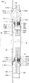
- FIG. 1 is a partially broken front view schematically showing a configuration of a torque damper device according to the present invention.
- FIG. 2 is a cross-sectional view schematically showing a configuration of a torque damper device taken along line 2-2 shown in FIG. 1.
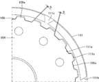
- FIG. 3 is a partially enlarged view showing details of a configuration within a dashed circle A shown in FIG. 2.
- FIG. 3 is a partially enlarged view showing details of a meshing portion between a first friction plate and an output hub shown in FIGS. 1 and 2 in a state where they are not meshed.
- FIG. 5 is a partially enlarged view showing a state where the first friction plate and the output hub shown in FIG. 4 are engaged with each other.
- FIG. 1 is a partially broken front view schematically showing a configuration of a torque damper device 100 according to the present invention.
- FIG. 2 is a cross-sectional view schematically showing the configuration of the torque damper device 100 as viewed from 2-2 shown in FIG.
- This torque damper device 100 is a machine mainly provided with an automatic transmission (so-called AT vehicle) that is provided between an engine and a transmission to reduce torque fluctuation of a driving force of the engine and transmit the torque to the transmission.
- AT vehicle automatic transmission
- the torque damper device 100 includes a first input plate 101 and a second input plate 102.
- the first input plate 101 and the second input plate 102 are components that are rotationally driven by a driving force from a vehicle engine (not shown), and are each formed by forming a metal material into a flat plate shape.
- the first input plate 101 and the second input plate 102 are opposed to each other with a gap between them, and are integrally connected by a plurality (four in the present embodiment) of rivets 103.
- a plurality of (four in the present embodiment) through-hole-shaped transmission body housing portions 101a, 102a are formed respectively, and hold an elastic transmission body 110 described later.
- the first input plate 101 forms one (left side in the figure) of the two side surfaces of the torque damper device 100, and is a plate holding hole formed of four through holes formed at equal intervals along the circumferential direction.
- a second intermediate plate 114 described later is held by 101b.
- the first input plate 101 is opposed to a position separated from a left end face in the figure of a flange body 107 described later, and a direction in which an inner peripheral edge portion 101c of the first input plate 101 is separated from the left end face (FIG. 2). At the left).
- a wide portion 108a is formed between the inner peripheral edge portion 101c and the flange body 107, and a narrow portion 108b is formed between the flange portion 107 and the opposing portion 101d outside the inner peripheral edge portion 101c.
- the second input plate 102 constitutes the other side (the right side in the figure) of the two sides of the torque damper device 100, and is a plate holding hole formed of eight through holes formed at equal intervals along the circumferential direction. 102b holds two first intermediate plates 112 described later.
- the first input plate 101 and the second input plate 102 are disposed to face each other via a flange body 107 extending from the output hub 104, and are integrally connected by a plurality (four in the present embodiment) of rivets 103. Have been.
- the first input plate 101 and the second input plate 102 are connected to an output shaft (not shown) such as an engine crankshaft, and integrally rotate.
- the output hub 104 is a component for outputting the rotational driving force input from the engine by the first input plate 101 and the second input plate 102 to the outside, and is formed by forming a metal material into a cylindrical shape. .
- the through hole at the center of the output hub 104 is a portion to which the input shaft 90 extending from the transmission, which is the output destination of the rotational driving force of the torque damper device 100, is connected.
- a spline for transmitting the driving force is formed.
- the outer peripheral portion of the output hub 104 is a portion that holds the flange body 107, the first friction plate 111, and the second friction plate 113, respectively, and has a cutout portion 104a and a friction plate holding portion 106, respectively.
- the notch portion 104a is a portion to which the flange body 107 is connected, and is formed by cutting out a part of the radially outer end portion of the output hub 104 in an annular shape in the thickness direction.
- the output hub 104 has a plurality of through holes formed along the circumferential direction at a portion corresponding to the notch portion 104a at the distal end portion, and penetrates these through holes and the flange body 107 in the axial direction.
- the flange body 107 is connected by the rivet 105.
- the flange body 107 is connected to the output hub 104 by twelve rivets 105.
- the rivet 105 is a component for integrally connecting the flange body 107 to the output hub 104, and has a head 105a in which both ends of a metal rod protrude radially outward in a disk shape.
- the rivet 105 connects the flange body 107 and the output hub 104 to each other with the head 105a protruding from each outer side surface of the flange body 107 and the output hub 104, respectively.
- the head portion 105a protruding from the side surface of the flange body 107 is formed to have a protruding amount that can be fitted and supported on an inner peripheral portion 113a of a second friction plate 113 described later.
- the head 105a is formed to have a thickness larger than the thickness of the second friction plate 113.
- the friction plate holding portion 106 is a portion that holds the first friction plate 111, and is formed at a radially outer end of the output hub 104 so as to extend in the axial direction.
- the friction plate holding portion 106 has a spline-shaped hub-side fitting portion 106a formed at a radially outer end portion of the output hub 104, and a plate formed on the inner peripheral portion of the first friction plate 111.
- the side fitting portion 111a is configured to fit.
- the friction plate holding portion 106 is formed to have a length in the axial direction longer than the total thickness of the first friction plate 111 and the first intermediate plate 112 which are overlapped with each other in the axial direction.
- the axial length of the friction plate holding portion 106 is formed to be longer than the total value of the thicknesses of the three first friction plates 111 and the two first intermediate plates 112. .
- the flange body 107 is a component for transmitting the rotational driving force input from the engine by the first input plate 101 and the second input plate 102 to the output hub 104, and is formed by forming a metal material into a flat annular shape. .
- the flange body 107 is disposed between the first input plate 101 and the second input plate 102, and the transmission body housing part that houses the elastic transmission body 110 at a position facing the transmission body housing parts 101a and 102a, respectively. 107a are formed.
- a portion between the transmission body accommodating portions 107a on the outer peripheral portion of the flange body 107 is formed so as to be recessed inward in the radial direction, and is formed so that the rivet 103 does not physically interfere.
- the flange body 107 has a lubricating liquid flow path 107b formed at a position facing the friction plate holding portion 106 in the output hub 104.
- the lubricating liquid flow path 107b is a through hole for guiding a lubricating liquid (not shown) flowing from the radially inner side through the narrow portion 108b to the friction plate holding part 106 side, and is provided at equal intervals along the circumferential direction.
- a plurality is formed. In the present embodiment, twelve lubricating liquid channels 107b are formed. That is, the torque damper device 100 according to the present embodiment is a wet-type torque damper device.
- the thickness of the flange body 107 is formed so as to fit in the notch 104a and be flush with the end face of the output hub 104 on the first input plate 101 side. As a result, a wide portion 108a and a narrow portion 108b are formed between the first input plate 101 and the end face of the flange body 107 on the first input plate 101 side.
- the wide portion 108a is a portion that receives the lubricating liquid discharged from the input shaft 90, and is a flow path formed in an annular shape between the inner peripheral portion 101c of the first input plate 101 and the side surface of the output hub 104. is there.
- the wide portion 108 a is formed so as to face each of the plurality of discharge ports 92 formed on the outer peripheral surface of the input shaft 90. 2 and 3, the flow of the lubricating liquid guided from the input shaft 90 into the torque damper device 100 is indicated by broken lines.
- the narrow portion 108b is a portion that guides the lubricating fluid that has flowed into the wide portion 108a to the second friction plate 113 and the lubricating fluid channel 107b, and is formed between the facing portion 101d of the first input plate 101 and the side surface of the flange body 107. It is formed in an annular shape with a width narrower than the wide portion 108a. Accordingly, the narrow portion 108b can increase the flow rate of the lubricating liquid flowing from the wide portion 108a to improve the cooling, cleaning, and lubricating properties of the second friction plate 113, and can reduce the lubricating liquid flow path 107b. The flowability to the first friction plate 111 via the first friction plate 111 can be improved.
- the narrow portion 108b may be formed to have a width relatively narrower than the wide portion 108a, one of the opposing end surfaces of the opposing portion 101d and the flange body 107 may protrude to the other side. May be formed. Therefore, the narrow portion 108b can also be formed by projecting at least a part of the end surface of the flange body 107 toward the facing portion 101d. Further, the wide portion 108a and the narrow portion 108b have a uniform width toward the outside in the radial direction, that is, even if the wide portion 108a or the narrow portion 108b is omitted, the flow of the lubricating liquid itself is secured. .
- the elastic transmission body 110 is a component for elastically transmitting the rotational driving force input from the engine by the first input plate 101 and the second input plate 102 to the output hub 104, and is configured by a metal coil spring. I have.
- the elastic transmission body 110 is fitted in a compressed and deformed state into transmission body housing portions 101a, 102a, 107a formed at positions facing each other in the first input plate 101, the second input plate 102, and the flange body 107. .
- the first friction plate 111 is a flat plate-shaped component pressed against the second input plate 102, the flange body 107, and the first intermediate plate 112, and punches a thin plate made of SPCC (cold rolled steel plate) into a ring. It is molded. On the inner peripheral portion of the first friction plate 111, a plate-side fitting portion 111a formed of an internal gear spline that is spline-fitted to a hub-side fitting portion 106a formed on the output hub 104 is formed. . In this case, as shown in FIG. 4 and FIG.
- the plate-side fitting portion 111a and the hub-side fitting portion 106a have a convex tooth-side circumferential length of the concave tooth side of the meshing spline teeth. Is formed longer than the length in the circumferential direction, and a gap S is formed in which the plate-side fitting portion 111a and the hub-side fitting portion 106a can be relatively displaced in the circumferential direction.
- a friction material 111b composed of a plurality of paper pieces is attached to both side surfaces in the axial direction of the first friction plate 111, and a groove 111c serving as a flow path of a lubricating liquid is formed between the friction materials.
- the first friction plates 111 are provided on the friction plate holding portion 106 alternately with the first intermediate plates 112 in the axial direction.
- three first friction plates 111 are provided on the friction plate holding unit 106.
- the two first friction plates 111 provided at both ends in the axial direction are connected to one (the right side in the drawing) of the two axial end portions of the flange body 107 and the flange body 107 of the second input plate 102. It is provided facing the respective inner side surfaces.
- the first intermediate plate 112 is a flat annular component pressed against the first friction plate 111, and is formed by annularly punching a thin plate made of SPCC (cold rolled steel plate).
- the first intermediate plate 112 is formed with a plate-shaped hooking portion 112a that projects outward in the radial direction while being bent at the outer peripheral portion, and is hooked on the plate holding hole 102b of the second input plate 102.
- four hook portions 112a are formed on the outer peripheral portion of the first intermediate plate 112 at equal intervals along the circumferential direction.
- the first intermediate plates 112 are provided on the friction plate holding portion 106 alternately with the first friction plates 111 in the axial direction.
- two first intermediate plates 112 are provided on the friction plate holding unit 106. That is, the second input plate 102 integrally holds the two first intermediate plates 112 via the eight plate holding holes 102b.
- the second friction plate 113 is a flat annular member pressed against the flange body 107 and the second intermediate plate 114, respectively, and is formed by annularly punching a thin plate made of SPCC (cold rolled steel plate).
- the second friction plate 113 has an inner peripheral portion 113a fitted and held at each radially outer edge of each head 105a of the twelve rivets 105 described above.
- friction materials made of a plurality of pieces of paper are attached to both axial side surfaces of the second friction plate 113, and grooves are formed between the friction materials. It is configured.
- the second friction plate 113 has a flow hole 113b formed in the flange body 107 at a position facing the lubricating liquid flow path 107b.
- the flow hole 113b is a through hole for guiding the lubricating liquid existing in the region (in the present embodiment, the narrow portion 108b) between the first input plate 101 and the flange body 107 to the lubricating liquid flow path 107b.
- eight flow holes 113b are formed radially inward of the friction material.
- the second friction plate 113 is provided on the outer side in the radial direction of each head 105 a of the twelve rivets 105, facing the other (left side in the drawing) side surface of the axially opposite ends of the flange body 107. .
- the second intermediate plate 114 is a flat annular component pressed against the second friction plate 113, and is formed by annularly punching a thin plate made of SPCC (cold rolled steel plate).
- the second intermediate plate 114 has a plate-shaped hooking portion 114a that is bent to the outer peripheral portion and protrudes outward in the radial direction, and the first input plate 101 In the plate holding hole 101b.
- four hook portions 114a are formed on the outer peripheral portion of the second intermediate plate 114 at equal intervals along the circumferential direction.
- the first input plate 101 integrally holds one second intermediate plate 114 via the four plate holding holes 101b.
- the second intermediate plate 114 is provided at a position radially outward from a portion of the first input plate 101 facing the facing portion 101d.
- a pressure body 115 is provided between the first input plate 101 and the second intermediate plate 114.
- the pressure body 115 presses the second friction plate 113 against the flange body 107 by pressing the second intermediate plate 114, and presses the first input plate 101 outward, thereby pressing the second input plate 102 to the first intermediate plate 112. And a component made of an elastic body for pressing the first friction plate 111 against the flange body 107.
- the pressure body 115 is formed by forming a flat ring-shaped spring steel into a weight shape. The pressure body 115 is provided at a position of the first input plate 101 facing the facing portion 101d.
- the operator fits the first friction plate 111 to the friction plate holding portion 106 of the output hub 104.
- the worker places the plate-side fitting portion 111a of the first friction plate 111 on the hub-side fitting portion 106a while alternately overlapping the first friction plates 111 and the first intermediate plates 112 from the flange body 107 side. Fit.
- the worker can easily receive the first friction plate 111 by providing the flange body 107 at one end (left side in the drawing) of the friction plate holding portion 106, so that the operator can easily perform the first operation in a state where the position in the axial direction is defined.
- the first friction plate 111 and the first intermediate plate 112 can be arranged on the friction plate holding portion 106 while alternately overlapping.
- the operator can determine the radial position by fitting the first friction plate 111 to the hub-side fitting portion 106a, and also allow the first intermediate plate 112 to be separated by the outer peripheral surface of the hub-side fitting portion 106a. Therefore, the first friction plates 111 and the first intermediate plates 112 can be easily arranged alternately on the friction plate holding portion 106 in a state where the position in the radial direction is defined.
- the operator arranges the second friction plate 113 adjacent to the side surface of the flange body 107 and attaches the second intermediate plate to the second friction plate 113.
- the plate 114 is arranged adjacent.
- the second friction plate 113 is easily positioned and arranged with respect to the flange body 107 because the radial position is defined by fitting the inner peripheral portion 113a to the head 105a of the rivet 105. Can be.
- the operator prepares the first input plate 101, the second input plate 102, the elastic transmission body 110, and the pressure body 115, and assembles them to the flange body 107.
- the worker after accommodating the elastic transmission members 110 in the four transmission member receiving portions 107a of the flange 107, respectively, arranges the second input plate 102 in opposition to the first intermediate plate 112 and alternates with each other.
- the first friction plate 111 and the first intermediate plate 112, which are overlapped with each other, are arranged so as to be sandwiched by the flange body 107.
- the worker accommodates the elastic transmission body 110 in the transmission body accommodation section 102a of the second input plate 102 and sets the hook 112a of the first intermediate plate 112 to the plate holding hole 102b of the second input plate 102. Hook on.
- the operator arranges the first input plate 101 to face the second intermediate plate 114 via the pressure body 115, and sandwiches the pressure body 115, the second intermediate plate 114, and the second friction plate 113 with the flange body 107. So that In this case, the worker accommodates the elastic transmission body 110 in the transmission body accommodation section 101a of the first input plate 101, and sets the hook 114a of the second intermediate plate 114 to the plate holding hole 101b of the first input plate 101. Hook on.
- the operator integrally connects the first input plate 101 and the second input plate 102 arranged on both axial sides of the flange body 107 with the rivets 103. Thereby, the operator can assemble the torque damper device 100.
- various adjustment operations and test operations are required to complete the torque damper device 100, but since these various operations are not directly related to the present invention, the description thereof will be omitted.
- the torque damper device 100 is disassembled for output adjustment, maintenance, or the like, it can be disassembled by a procedure reverse to the above-described assembly procedure.
- the completed torque damper device 100 is assembled on a power transmission path between the engine and the transmission in an automobile assembling process.
- the input shaft 90 extending from the transmission is fitted and connected to the inner peripheral surface of the output hub 104.
- a lubricating liquid supply passage 91 for supplying lubricating liquid into the torque damper device 100 is formed in the input shaft 90 so as to extend in the axial direction, and a plurality of lubricating liquid supply passages 91 on the outer peripheral surface of the input shaft 90 are formed. Open at the location.
- the discharge ports 92 which are openings of the lubricating liquid supply passage 91, are formed at a plurality of positions on the outer peripheral surface of the input shaft 90 facing the wide portion 108a. ing.
- the lubricating liquid oil or the like that can ensure the cooling property, the cleaning property and the lubricating property of the first friction plate 111 and the second friction plate 113 is mainly used.
- This torque damper device 100 is disposed between an engine and a transmission in a vehicle, and absorbs torque fluctuations from the engine during idling when the engine is started and the vehicle is stopped while the vehicle is not running. Transmit to the transmission.
- the first input plate 101 and the second input plate 102 are driven to rotate integrally by the rotational driving force from the engine, and the first input plate 101 and the second input plate
- the first intermediate plate 112 and the second intermediate plate 114 integrally connected to 102 also rotate integrally.
- the flange body 107 and the output hub 104 are elastically connected to the first input plate 101 and the second input plate 102 via the elastic transmission body 110, respectively, the first input plate 101 and the second input plate It is driven to rotate together with the plate 102.
- first friction plate 111 meshed with the output hub 104 via the friction plate holding portion 106 is brought into close contact with the first intermediate plate 112 by the elastic force of the pressure body 115 and is also provided on the flange body 107 and the second input plate 102. Each is in close contact. Thereby, the first friction plate 111 drives the output hub 104 to rotate.
- the second friction plate 113 is in close contact with the second intermediate plate 114 and the flange body 107 by the elastic force of the pressure member 115. Accordingly, the second friction plate 113 drives the output hub 104 to rotate.
- the torque damper device 100 when a small torque fluctuation occurs in the rotational driving force from the engine, the torque damper device 100 includes at least the first friction plate 111 and the second friction plate 113 which are in close contact with the flange body 107.
- One of the members slides frictionally with at least one of the flange body 107, the first intermediate plate 112, and the second intermediate plate 114 to generate low hysteresis.
- the torque damper device 100 absorbs the small torque fluctuation due to low hysteresis generated by at least one of the first friction plate 111 and the second friction plate 113 that are in close contact with the flange body 107 and frictionally sliding.
- the torque damper device 100 When torque fluctuation larger than the small torque fluctuation occurs in the rotational driving force from the engine, the torque damper device 100 generates a high hysteresis in addition to the low hysteresis. Specifically, in the torque damper device 100, as shown in FIG. 5, the tooth surface at which the hub-side fitting portion 106a of the output hub 104 and the plate-side fitting portion 111a of the first friction plate 111 mesh with each other is large. By shifting to the tooth surface on the side where the gap S is formed due to the torque fluctuation, frictional sliding occurs between the first friction plate 111 and the first intermediate plate 112, and high hysteresis occurs.
- the torque damper device 100 a tooth surface in which the hub-side fitting portion 106a of the output hub 104 and the plate-side fitting portion 111a of the first friction plate 111 mesh with each other is formed on the opposite side in the circumferential direction from the tooth surface. High hysteresis is not generated until the gap S that has been formed is eliminated and the tooth surfaces forming the gap S mesh with each other. As a result, the torque damper device 100 has the large torque fluctuation due to the high hysteresis generated when the first friction plate 111 frictionally slides between the flange body 107, the first intermediate plate 112, and the second input plate 102. Absorb some or all of
- lubricating liquid is supplied from the input shaft 90 when the engine is operating.
- the lubricating liquid discharged from the discharge port 92 of the input shaft 90 forms a wide portion 108 a formed by the first input plate 101 and the output hub 104 and a narrow portion formed by the first input plate 101 and the flange body 107.
- the friction plate holding portion 106 and the friction plate holding portion 106 are supplied to the second friction plate 113 through the lubricating fluid passage 107b formed in the flange body 107 and the circulation hole 113b formed in the second friction plate 113, respectively. It is supplied to the first friction plate 111. Thereby, the second friction plate 113 and the first friction plate 111 are cooled, cleaned and lubricated.
- the displacement of the torque damper device 100 in the radial direction is restricted by fitting to the outer peripheral surface of the output hub 104 to which the input shaft 90 is connected.
- a hub-side fitting portion 106a for holding the plurality of first friction plates 111 in a state in which displacement in the axial direction is allowed while restricting displacement in the circumferential direction is formed on the outer peripheral surface of the hub.
- the torque damper device 100 can hold the hub-side fitting portion 106a simply by inserting the plurality of first friction plates 111 from the axial direction, the first friction plates 111 for generating high hysteresis can be held. Can be improved in ease of assembly and maintenance.
- the torque damper device 100 is configured to include the three first friction plates 111 and the two first intermediate plates 112.
- the torque damper device 100 may be configured to include the plurality of first friction plates 111 and the plurality of first intermediate plates 112.
- the torque damper device 100 can reduce the operational and economical burden when manufacturing the torque damper device 100.
- the first friction plate 111 may be configured to include the first friction plate 111 in which the plate-side fitting portions 111a having different gaps S between the plurality of first friction plates 111 are formed. According to this, the torque damper device 100 can set a plurality of timings at which a high hysteresis is generated, and generate a high hysteresis for each finer variation with respect to the engine torque variation, that is, increase the number of stages of the hysteresis. Can be done.
- the torque damper device 100 is configured to form the gap S between the plate-side fitting portion 111a of the first friction plate 111 and the hub-side fitting portion 106a of the output hub 104. . That is, the plate-side fitting portion 111a and the hub-side fitting portion 106a are formed such that the circumferential length of the concave tooth side of the meshing spline teeth is longer than the circumferential length of the convex tooth side.
- a gap S is formed in which the side fitting portion 111a and the hub side fitting portion 106a can be relatively displaced in the circumferential direction.
- the plate-side fitting portion 111a and the hub-side fitting portion 106a are formed such that the circumferential length of the concave tooth side and the circumferential length of the convex tooth side of the meshing spline teeth are substantially the same. Then, the plate-side fitting portion 111a and the hub-side fitting portion 106a may be formed so as to fit in a state in which relative displacement is not possible in the circumferential direction. According to this, the torque damper device 100 can immediately generate high hysteresis with respect to the torque fluctuation from the engine.
- the torque damper device 100 is configured to include the second friction plate 113 and the second intermediate plate 114, respectively. Accordingly, the torque damper device 100 can enhance the hysteresis generated by the first friction plate 111. Further, the torque damper device 100 can suppress the torque fluctuation by generating the hysteresis even when the first friction plate 111 has a low torque fluctuation that does not cause the hysteresis.
- the torque damper device 100 may be configured by omitting the second friction plate 113 and the second intermediate plate 114, respectively. In this case, in the torque damper device 100, the pressure body 115 may be provided between the second input plate 102 and the flange body 107, or may be provided between the first input plate 101 and the flange body 107.
- the first intermediate plate 112 is provided between the flange body 107 and the first friction plate 111, and the pressure body 115 is provided between the first intermediate plate 112 and the flange body 107.
- the torque damper device 100 includes a first intermediate plate 112 provided between the second input plate 102 and the first friction plate 111, and a first intermediate plate 112 provided between the first intermediate plate 112 and the second input plate 102.
- a pressure body 115 can be provided.
- two first intermediate plates 112 may be provided between the two first friction plates 111, and the pressure body 115 may be provided between the two first intermediate plates 112.
- a second intermediate plate 114 is provided between the flange body 107 and the first input plate 101, and a pressure body 115 is provided between the first input plate 101 and the second intermediate plate 114.
- the torque damper device 100 is configured such that the output hub 104 and the flange body 107 are formed separately from each other and connected by the rivets 105.
- the output hub 104 and the flange body 107 can also be configured as one integrated part.
- the second friction plate 113 has a convex shape such that all or a part of the inner peripheral portion 113a of the second friction plate 113 is fitted to the side surface of the output hub 104 on which the flange body 107 is integrally formed. It is preferable to provide a protruding projection.
- the flange body 107 is formed by forming the lubricating liquid flow path 107b at a position facing the friction plate holding portion 106.
- the flange body 107 can also be formed at a position where the lubricating liquid flow path 107b is shifted with respect to the friction plate holding section 106, for example, at a position radially outside the friction plate holding section 106.
- the flange body 107 may be configured by omitting the lubricating liquid flow path 107b.
- the second friction plate 113 can be configured by omitting the flow holes 113b.
- the hub-side fitting portion 106a and the plate-side fitting portion 111a are configured with a large number of spline teeth.
- the hub-side fitting portion 106a and the plate-side fitting portion 111a may be configured to include at least one concave and one convex portion that mesh with each other.
Landscapes
- Engineering & Computer Science (AREA)
- General Engineering & Computer Science (AREA)
- Mechanical Engineering (AREA)
- Physics & Mathematics (AREA)
- Acoustics & Sound (AREA)
- Aviation & Aerospace Engineering (AREA)
- Mechanical Operated Clutches (AREA)
Priority Applications (5)
| Application Number | Priority Date | Filing Date | Title |
|---|---|---|---|
| KR1020207036364A KR20210032313A (ko) | 2018-08-01 | 2019-07-12 | 토크 댐퍼 장치 |
| MX2021000986A MX2021000986A (es) | 2018-08-01 | 2019-07-12 | Dispositivo amortiguador de fuerza de torsion. |
| CN201980042881.4A CN112352119B (zh) | 2018-08-01 | 2019-07-12 | 扭矩缓冲器装置 |
| EP19843884.8A EP3832160A4 (en) | 2018-08-01 | 2019-07-12 | TORQUE DAMPER |
| US17/258,650 US20210270324A1 (en) | 2018-08-01 | 2019-07-12 | Torque damper device |
Applications Claiming Priority (2)
| Application Number | Priority Date | Filing Date | Title |
|---|---|---|---|
| JP2018-145089 | 2018-08-01 | ||
| JP2018145089A JP6666605B2 (ja) | 2018-08-01 | 2018-08-01 | トルクダンパー装置 |
Publications (1)
| Publication Number | Publication Date |
|---|---|
| WO2020026775A1 true WO2020026775A1 (ja) | 2020-02-06 |
Family
ID=69230734
Family Applications (1)
| Application Number | Title | Priority Date | Filing Date |
|---|---|---|---|
| PCT/JP2019/027774 WO2020026775A1 (ja) | 2018-08-01 | 2019-07-12 | トルクダンパー装置 |
Country Status (7)
| Country | Link |
|---|---|
| US (1) | US20210270324A1 (ko) |
| EP (1) | EP3832160A4 (ko) |
| JP (1) | JP6666605B2 (ko) |
| KR (1) | KR20210032313A (ko) |
| CN (1) | CN112352119B (ko) |
| MX (1) | MX2021000986A (ko) |
| WO (1) | WO2020026775A1 (ko) |
Families Citing this family (1)
| Publication number | Priority date | Publication date | Assignee | Title |
|---|---|---|---|---|
| KR102594503B1 (ko) * | 2021-11-25 | 2023-10-27 | 주식회사 카펙발레오 | 토셔널 댐퍼 및 이를 구비한 하이브리드 구동 모듈 |
Citations (6)
| Publication number | Priority date | Publication date | Assignee | Title |
|---|---|---|---|---|
| JPH06129490A (ja) * | 1992-10-16 | 1994-05-10 | Nissan Motor Co Ltd | トーショナルダンパの振動減衰装置 |
| JP2002266943A (ja) * | 2001-03-09 | 2002-09-18 | Exedy Corp | ダンパー機構 |
| EP1521013A1 (en) * | 2003-10-03 | 2005-04-06 | Automotive Products Driveline Technology Limited | Twin mass flywheel |
| JP2011247425A (ja) * | 2011-08-04 | 2011-12-08 | Aisin Seiki Co Ltd | トルク変動吸収装置 |
| JP2016142339A (ja) | 2015-02-02 | 2016-08-08 | 株式会社ユタカ技研 | トルク変動吸収装置 |
| US20170152913A1 (en) * | 2015-11-30 | 2017-06-01 | Eaton Corporation | Clutch pack with robust hysteresis |
Family Cites Families (11)
| Publication number | Priority date | Publication date | Assignee | Title |
|---|---|---|---|---|
| FR2381944A1 (fr) * | 1977-02-25 | 1978-09-22 | Ferodo Sa | Dispositif amortisseur de torsion, en particulier friction d'embrayage a moyeu amortisseur pour vehicule automobile |
| US4431100A (en) * | 1980-07-16 | 1984-02-14 | Kabushiki Kaisha Komatsu Seisakusho | Torque fluctuation damper |
| JPS6113031A (ja) * | 1984-06-27 | 1986-01-21 | Atsugi Motor Parts Co Ltd | クラツチデイスク |
| JPH0617878A (ja) * | 1992-07-06 | 1994-01-25 | Nissan Motor Co Ltd | トーショナルダンパの振動減衰装置 |
| EP1176338B1 (en) * | 2000-07-24 | 2005-02-16 | Valeo Unisia Transmissions Kabushiki Kaisha | Torsional vibration damper |
| JP2002181131A (ja) * | 2000-12-12 | 2002-06-26 | Valeo Unisia Transmission Kk | トルク伝達装置 |
| GB0124246D0 (en) * | 2001-10-10 | 2001-11-28 | Ap Tmf Ltd | Torsional vibration dampers |
| GB0126726D0 (en) * | 2001-11-07 | 2002-01-02 | Ap Tmf Ltd | Twin mass flywheel |
| JP2009041737A (ja) * | 2007-08-10 | 2009-02-26 | Exedy Corp | 流体式トルク伝達装置 |
| JP2010216524A (ja) * | 2009-03-13 | 2010-09-30 | Toyota Motor Corp | 車両用トルクリミッタ装置 |
| WO2012168997A1 (ja) * | 2011-06-06 | 2012-12-13 | トヨタ自動車株式会社 | 車両用トルクリミッタ装置 |
-
2018
- 2018-08-01 JP JP2018145089A patent/JP6666605B2/ja active Active
-
2019
- 2019-07-12 MX MX2021000986A patent/MX2021000986A/es unknown
- 2019-07-12 US US17/258,650 patent/US20210270324A1/en not_active Abandoned
- 2019-07-12 WO PCT/JP2019/027774 patent/WO2020026775A1/ja unknown
- 2019-07-12 EP EP19843884.8A patent/EP3832160A4/en active Pending
- 2019-07-12 KR KR1020207036364A patent/KR20210032313A/ko unknown
- 2019-07-12 CN CN201980042881.4A patent/CN112352119B/zh active Active
Patent Citations (6)
| Publication number | Priority date | Publication date | Assignee | Title |
|---|---|---|---|---|
| JPH06129490A (ja) * | 1992-10-16 | 1994-05-10 | Nissan Motor Co Ltd | トーショナルダンパの振動減衰装置 |
| JP2002266943A (ja) * | 2001-03-09 | 2002-09-18 | Exedy Corp | ダンパー機構 |
| EP1521013A1 (en) * | 2003-10-03 | 2005-04-06 | Automotive Products Driveline Technology Limited | Twin mass flywheel |
| JP2011247425A (ja) * | 2011-08-04 | 2011-12-08 | Aisin Seiki Co Ltd | トルク変動吸収装置 |
| JP2016142339A (ja) | 2015-02-02 | 2016-08-08 | 株式会社ユタカ技研 | トルク変動吸収装置 |
| US20170152913A1 (en) * | 2015-11-30 | 2017-06-01 | Eaton Corporation | Clutch pack with robust hysteresis |
Non-Patent Citations (1)
| Title |
|---|
| See also references of EP3832160A4 |
Also Published As
| Publication number | Publication date |
|---|---|
| JP2020020408A (ja) | 2020-02-06 |
| US20210270324A1 (en) | 2021-09-02 |
| EP3832160A4 (en) | 2022-05-04 |
| KR20210032313A (ko) | 2021-03-24 |
| MX2021000986A (es) | 2021-04-12 |
| JP6666605B2 (ja) | 2020-03-18 |
| CN112352119B (zh) | 2022-09-30 |
| EP3832160A1 (en) | 2021-06-09 |
| CN112352119A (zh) | 2021-02-09 |
Similar Documents
| Publication | Publication Date | Title |
|---|---|---|
| CN110273947B (zh) | 自动变速器 | |
| CN110273946B (zh) | 自动变速器 | |
| US11149831B2 (en) | Lock-up device for torque converter | |
| US9010508B2 (en) | Starting apparatus | |
| JP2017166672A (ja) | トルクコンバータ | |
| JP6666605B2 (ja) | トルクダンパー装置 | |
| CN110273937B (zh) | 自动变速器 | |
| US20200096050A1 (en) | Power transmission device | |
| JP2011185382A (ja) | ダンパ装置および流体伝動装置 | |
| JP2004125074A (ja) | 流体式トルク伝達装置のロックアップ装置 | |
| JP2017166669A (ja) | トルクコンバータのロックアップ装置 | |
| CN113757336A (zh) | 扭矩缓冲器装置以及变矩器 | |
| JP2017166668A (ja) | トルクコンバータのロックアップ装置 | |
| CN113366235B (zh) | 湿式双离合器和用于这种湿式双离合器的弹性回复装置 | |
| JP6958502B2 (ja) | 自動変速機 | |
| JP2004156692A (ja) | 流体式トルク伝達装置のロックアップ装置 | |
| JP6034641B2 (ja) | 発進装置 | |
| JP2020101271A (ja) | 自動変速機 | |
| CN112049914A (zh) | 扭矩减振装置 | |
| JP6435855B2 (ja) | クラッチおよびそれを備えた変速装置 | |
| JP2020502447A (ja) | 自動車のトランスミッションに装備するためのトルク伝達モジュール | |
| JP7198145B2 (ja) | 動力伝達装置 | |
| US11162541B2 (en) | Torque transmission apparatus | |
| JP2021181795A (ja) | 動力伝達装置 | |
| US20200096077A1 (en) | Power transmission device |
Legal Events
| Date | Code | Title | Description |
|---|---|---|---|
| 121 | Ep: the epo has been informed by wipo that ep was designated in this application |
Ref document number: 19843884 Country of ref document: EP Kind code of ref document: A1 |
|
| NENP | Non-entry into the national phase |
Ref country code: DE |
|
| ENP | Entry into the national phase |
Ref document number: 2019843884 Country of ref document: EP Effective date: 20210301 |