WO2020021615A1 - ワーク自動搬送機 - Google Patents
ワーク自動搬送機 Download PDFInfo
- Publication number
- WO2020021615A1 WO2020021615A1 PCT/JP2018/027617 JP2018027617W WO2020021615A1 WO 2020021615 A1 WO2020021615 A1 WO 2020021615A1 JP 2018027617 W JP2018027617 W JP 2018027617W WO 2020021615 A1 WO2020021615 A1 WO 2020021615A1
- Authority
- WO
- WIPO (PCT)
- Prior art keywords
- work
- arm
- workpiece
- arm member
- robot arm
- Prior art date
- Legal status (The legal status is an assumption and is not a legal conclusion. Google has not performed a legal analysis and makes no representation as to the accuracy of the status listed.)
- Ceased
Links
Images




Classifications
-
- B—PERFORMING OPERATIONS; TRANSPORTING
- B23—MACHINE TOOLS; METAL-WORKING NOT OTHERWISE PROVIDED FOR
- B23Q—DETAILS, COMPONENTS, OR ACCESSORIES FOR MACHINE TOOLS, e.g. ARRANGEMENTS FOR COPYING OR CONTROLLING; MACHINE TOOLS IN GENERAL CHARACTERISED BY THE CONSTRUCTION OF PARTICULAR DETAILS OR COMPONENTS; COMBINATIONS OR ASSOCIATIONS OF METAL-WORKING MACHINES, NOT DIRECTED TO A PARTICULAR RESULT
- B23Q7/00—Arrangements for handling work specially combined with or arranged in, or specially adapted for use in connection with, machine tools, e.g. for conveying, loading, positioning, discharging, sorting
Definitions
- the present invention relates to an automatic workpiece transfer device that controls the attitude of an articulated robot arm according to the size of a workpiece.
- Patent Literature 1 discloses an automatic workpiece transfer machine in which an articulated robot arm having a robot hand at its tip moves by a traveling platform.
- the upper arm member and the forearm member are connected via a joint mechanism, and the robot hand at the distal end can be moved to a predetermined position by deformation between a folded state and an extended state. Therefore, the articulated robot arm is moved to a corresponding position in a folded state, extends to the machine tool and enters the machining room, and the robot hand transfers the workpiece.
- a reversing device is mounted on a traveling platform together with an articulated robot arm, so that a workpiece received by a robot hand can be reversed on the traveling platform.
- the posture control has been performed so far in which the posture (angle) of the upper arm member is kept constant and the folding angle of the forearm member is adjusted. This is to maintain a safe posture in which the articulated robot arm does not come into contact with a wall or the like when turning or moving in a narrow transport space. Therefore, in the conventional automatic work transfer machine, if the size of the work to be handled changes, it is necessary to change the setup of adjusting the height of the reversing device accordingly, which is very troublesome.
- an object of the present invention is to provide an automatic workpiece transfer device that performs attitude control of an articulated robot arm according to the size of a workpiece in order to solve the above-described problem.
- An automatic workpiece transfer device includes a traveling platform movable along a guide rail, a first arm member mounted on the traveling platform, and rotatably supported by a first joint with respect to a support member, A second arm member rotatably supported by a second joint with respect to the first arm member; a multi-joint robot arm including a robot hand attached to the second arm member; A reversing device for transferring a work to and from a robot arm, and, when transferring the work to the reversing device, adjusting the angle between the first arm member and the second arm member according to the size of the work.
- a control device for controlling the attitude of the joint robot arm.
- the angle between the first arm member and the second arm member of the articulated robot arm is adjusted according to the size of the work.
- FIG. 2 is a simplified block diagram illustrating a control system of the automatic workpiece transfer device.
- FIG. 7 is a diagram illustrating a conventional attitude control for an articulated robot arm.
- FIG. 4 is a diagram illustrating attitude control of the present embodiment for an articulated robot arm.
- FIG. 1 is a front view showing the processing machine line.
- various operation modules 101 in which machine tools and the like are modularized are arranged in the machine body width direction.
- a work loading module serving as a work loading section is installed at the right end of the drawing, and various work modules 101 such as a lathe, a machining center, and a measuring machine are arranged between the work loading module at the left end of the drawing and the work discharging module. is set up.
- FIG. 2 is a perspective view showing a work module 101 (particularly, a lathe module) and a front cover 103 which constitute the processing machine line 100.
- the work module 101 is mounted on the base 105 in a state where the work modules 101 are close to each other.
- a rail 151 is laid on the base 105, and the working module 101 is configured such that a processing machine body such as a lathe or a machining center is mounted on a movable bed having wheels. Therefore, the work module 101 mounted on the base 105 can move in the front-rear direction (Z-axis direction) along the rail 151.
- the work module 101 is provided with a front cover 103 protruding forward as shown in the figure. In the processing machine line 100, the front cover 103 forms one continuous transfer space 108 in the Y-axis direction. An automatic work transfer device is incorporated in the transfer space 108.
- FIG. 3 is a perspective view showing the automatic work transfer device of the present embodiment, and particularly shows a state in which the work is transferred to and from the work module 101.
- a traveling device 3 is mounted on a front portion of a base 105 on which a work module 101 is mounted, and the articulated robot arm 1 is mounted on the traveling device 3.
- the articulated robot arm 1 enters the inside of the work module 101 in an extended posture as shown in the drawing, and moves in the transport space 108 in a folded and compact standing state.
- the traveling device 3 has a support plate 21 attached to the front surface of a base 105, and a rack 22 and two rails 23 arranged in parallel are fixed to the support plate 21 in the horizontal direction.
- the traveling stand 25 is provided with a slide slidable with respect to the rail 23, and can move in the lateral direction according to the rail 23.
- a traveling motor 26 is fixed to the traveling platform 25, and a pinion 27 attached to a rotating shaft meshes with the rack 22. Therefore, the traveling motor 25 is driven and the pinion 27 rolls on the rack 22, so that the traveling platform 25 can move on the front surface of the base 13 along the rail 23.
- the articulated robot arm 1 is mounted on the traveling platform 25 via the turning table 18.
- an upper arm member 11 is connected via a first joint 13 to a support base 19 fixed to a turning table 18, and the upper arm member 11 is further connected to a forearm member via a second joint 14. 12 are connected.
- the angles of the upper arm member 11 and the forearm member 12 are adjusted by the rotation control of the joint motors of the first joint 13 and the second joint 14, and the articulated robot arm 1 is in an extended state as illustrated. And a folded state as described later.
- the articulated robot arm 1 is configured such that the folded forearm member 12 fits in the upper arm member 11. Therefore, the upper arm member 11 has a pair of left and right upper arm plates integrated by a back plate, and has a U-shaped cross section so as to provide a storage space inside.
- the forearm member 12 is constituted by a pair of left and right parallel forearm plates connected to the storage space side thereof via a second joint 14, and a robot hand 15 is attached to the free end side, that is, the tip of the articulated robot arm 1. ing.
- the robot hand 15 is rotatably mounted on the forearm member 12 by a rotation axis parallel to the rotation axes of the first and second joints 13 and 14. Hydraulic chucks for gripping the work are provided on both front and back surfaces. It is configured.
- the automatic work transfer machine 10 of the present embodiment is equipped with a reversing device 5 for reversing the work on the traveling platform 25.
- the reversing device 5 is assembled to a support base 19 of the articulated robot arm 1 fixed to the turning table 18.
- the reversing device 5 is configured such that a pair of gripping claws 17 can be opened and closed by a gripping cylinder to grip a workpiece.
- the reversing device 5 is provided with a rotation actuator that generates rotation using compressed air as a working fluid so that the work clamped by the gripping claws 17 can be rotated 180 ° about a vertical rotation axis. Has become.
- FIG. 4 is a simplified block diagram showing a control system of the automatic workpiece transfer machine 10.
- the control device 7 is mainly a computer including a storage device such as a ROM 32, a RAM 43, and a non-volatile memory 34 in addition to the CPU 31, and the articulated robot arm 1, the traveling device 3, It is connected to each drive unit of the device 5.
- a control device is mounted on each work module 101, and although not shown in detail, a LAN in which the control device on the work machine side and the control device 7 of the automatic work transfer machine 10 are connected via a concentrator. Has been built. Further, as shown in FIG. 1 and the like, the work module 101 has a touch panel type or a button type input unit, and displays operation information, an operation screen, and the like, and an operation display that enables a worker to input a set value. A device 107 is provided and connected to each control device via a LAN. Therefore, it is possible to input numerical values for the control of the automatic work transfer machine 10 from the operation display device 107.
- the control device 7 of the automatic work transfer machine 10 stores, in a memory, a transfer program for controlling a transfer route of the work to the plurality of work modules 101, a transfer posture of the articulated robot arm 1, and the like.
- a posture control program 341 for controlling the posture of the articulated robot arm 1 according to the size of the work when the work is transferred to the reversing device 5 is stored. From the operation display device 107, numerical values for controlling the posture of the articulated robot arm 1, that is, input of work dimensions and the like are performed.
- the articulated robot arm 1 moves in the transfer space 108 of the processing machine line 100, deforms as shown in FIG. Delivery takes place.
- the work is delivered from the robot hand 15 of the articulated robot arm 1 to the reversing device 5, and the gripping claws 17 rotate to move the work.
- the robot hand 15 is returned to the robot hand 15 again.
- FIG. 5 is a diagram showing a conventional attitude control for the articulated robot arm 1.
- the posture of the upper arm member 11 at a fixed angle was set such that the upper arm shaft 41 connecting the rotation axes of the first joint 13 and the second joint 14 was substantially vertical.
- the operation angle ⁇ n ( ⁇ 1, ⁇ 2) of the forearm shaft 42 connecting the two rotation axes of the second joint and the robot hand 15 has been adjusted according to the size of the workpiece W (W1, W2).
- AA pattern and B pattern shown in FIG. 5 show a state in which the articulated robot arm 1 transfers works W1 and W2 having different thicknesses Tn (T1, T2) to the reversing device 5.
- Tn thicknesses
- the operation angles ⁇ 1 and ⁇ 2 of the forearm shaft 42 and the distance (transfer height) Hn between the first joint 13 and the rotation axis (center of the workpiece Wn) of the robot hand 15 are determined. H1, H2).
- the difference in the size of the work Wn causes the difference in the transfer position of the robot hand 15, which has heretofore been adjusted by adjusting the operation angle ⁇ n of the forearm shaft 42.
- the difference in the delivery height Hn may be too large, and proper delivery between the robot hand 15 and the reversing device 5 may not be possible. Therefore, when the size of the work Wn to be handled changes, the operator needs to perform a setup change for adjusting the mounting height of the reversing device 5. Therefore, there has been a problem that a delivery error may occur and that the setup of the reversing device 5 needs to be changed for reliable delivery.
- FIG. 6 is a diagram illustrating attitude control of the present embodiment for the articulated robot arm 1.
- control is performed so that the gripping claws 17 of the reversing device 5 can grip the workpiece Wn in the same state by a combination of the operation angles ⁇ n of the upper arm axis 41 and the forearm axis 42.
- the same gripping state of the workpiece W by the reversing device 5 means that the gripping claw 17 grips the workpiece Wn at the central portion of the thickness Tn as in the related art, and furthermore, the rotation of the first joint 13 and the robot hand 15 This means that the distance (transfer height) Hx from the axis (the center of the workpiece Wn) becomes constant. This is because, by keeping the delivery height Hx constant, the gripping claws 17 always grip the central portion of the work Wn.
- the operation angle ⁇ 32 of the upper arm axis 41 with respect to the vertical reference line 40 is larger than the operation angle ⁇ 42 of the upper arm member 41 in the case of the work W2 having a small size. It became posture. Then, the operation angle ⁇ 31 of the forearm axis 42 with respect to the upper arm axis 41 in the case of the work W1 is smaller than the operation angle ⁇ 41 in the case of the work W2.
- the operator inputs the workpiece size Tn from the operation display device 107, and the multi-joint robot arm 1 and the reversing device Therefore, it is possible to eliminate the need for stable delivery of the workpiece to and the changeover of the reversing device 5.
- the tilt angle range ⁇ dn of the operable upper arm shaft 41 is set based on the size of the transport space 108. Therefore, when the upper arm shaft 41 is tilted within the tilt angle range ⁇ dn, operations such as reversal of the robot hand 15 and turning of the articulated robot arm 1 are performed. On the other hand, when the workpiece W is delivered in a posture in which the upper arm member 11 is inclined beyond the inclination angle range ⁇ dn, the upper arm shaft 41 is raised vertically so as to fall within the inclination angle range ⁇ dn. The articulated robot arm 1 does not interfere.
Landscapes
- Engineering & Computer Science (AREA)
- Mechanical Engineering (AREA)
- Manipulator (AREA)
- Feeding Of Workpieces (AREA)
- Multi-Process Working Machines And Systems (AREA)
Abstract
ワークのサイズに応じた多関節ロボットアームの姿勢制御を行うワーク自動搬送機であり、ガイドレールに沿って移動可能な走行台と、前記走行台に搭載され、支持部材に対して第1関節によって回転支持された第1アーム部材、前記第1アーム部材に対して第2関節によって回転支持された第2アーム部材および、前記第2アーム部材に取り付けられたロボットハンドを備える多関節ロボットアームと、前記走行台に搭載され、前記多関節ロボットアームとの間でワークの受渡しを行う反転装置と、前記反転装置にワークを受渡しする際、ワークのサイズに応じて前記第1アーム部材と前記第2アーム部材との角度調整によって、前記多関節ロボットアームの姿勢制御を行う制御装置とを有する。
Description
本発明は、ワークのサイズに応じた多関節ロボットアームの姿勢制御を行うワーク自動搬送機に関する。
複数の工作機械が並べられた加工機械ラインは、各工作機械との間でワークの受渡しを行うワーク自動搬送機が設けられている。下記特許文献1には、先端部にロボットハンドを備えた多関節ロボットアームが走行台によって移動するワーク自動搬送機が開示されている。この多関節ロボットアームは、上腕部材と前腕部材とが関節機構を介して連結され、折り畳み状態と伸び状態との変形によって、先端部のロボットハンドを所定の位置へと移動させることができる。そのため、多関節ロボットアームは、折り畳まれた状態で該当する位置へと移され、工作機械に対しては伸びて加工室内へと進入し、ロボットハンドによってワークの受渡しが行われる。
前述した従来のワーク自動搬送機は、走行台の上に多関節ロボットアームと一緒に反転装置が搭載され、ロボットハンドが受け取ったワークを走行台の上で反転させることが可能になっている。そうした多関節ロボットアームと反転装置とのワークの受渡しは、これまで上腕部材の姿勢(角度)を一定にし、前腕部材の折り畳む角度を調節するようにした姿勢制御が行われていた。これは狭い搬送空間内での旋回や移動の際、多関節ロボットアームが壁などに接触しない安全な姿勢を維持させるためである。よって、従来のワーク自動搬送機では、取り扱うワークの大きさが変わると、それに応じて反転装置の高さを調整する段取り替えが必要になり、非常に手間であった。
そこで、本発明は、かかる課題を解決すべく、ワークのサイズに応じた多関節ロボットアームの姿勢制御を行うワーク自動搬送機を提供することを目的とする。
本発明の一態様におけるワーク自動搬送機は、ガイドレールに沿って移動可能な走行台と、前記走行台に搭載され、支持部材に対して第1関節によって回転支持された第1アーム部材、前記第1アーム部材に対して第2関節によって回転支持された第2アーム部材および、前記第2アーム部材に取り付けられたロボットハンドを備える多関節ロボットアームと、前記走行台に搭載され、前記多関節ロボットアームとの間でワークの受渡しを行う反転装置と、前記反転装置にワークを受渡しする際、ワークのサイズに応じて前記第1アーム部材と前記第2アーム部材との角度調整によって、前記多関節ロボットアームの姿勢制御を行う制御装置とを有する。
前記構成によれば、多関節ロボットアームと反転装置との間でワークの受渡しを行う際、ワークのサイズに応じて多関節ロボットアームの第1アーム部材と第2アーム部材との角度を調整する姿勢制御を行うことにより、取り扱うワークのサイズが変わったとしても同じように受渡しでき、反転装置の段取り替えを行う必要がなくなる。
次に、本発明に係るワーク自動搬送機の一実施形態について、図面を参照しながら以下に説明する。本実施形態では、従来例と同様に加工機械ラインに組み込まれたワーク自動搬送機を例に挙げて説明する。図1は、その加工機械ラインを示した正面図である。加工機械ライン100は、工作機械などがモジュール化された各種の作業モジュール101が機体幅方向に並べられている。具体的には、図面右端にワーク搬入部となるワーク搬入モジュールが設置され、図面左端のワーク搬出部であるワーク排出モジュールまでの間に、旋盤やマシニングセンタ或いは検測機など各種の作業モジュール101が設置されている。
加工機械ライン100は、全ての作業モジュール101が同じ形状の外装カバー102によって覆われている。そして、外装カバー102の前部には開閉可能な前カバー103が形成され、加工機械ライン100全体において幅方向に広がった搬送空間108(図2参照)が設けられている。ここで、図2は、加工機械ライン100を構成する作業モジュール101(特に、旋盤モジュール)と前カバー103を示した斜視図である。
作業モジュール101は、隣同士が接近した状態でベース105の上に搭載されている。ベース105にはレール151が敷設され、作業モジュール101は、車輪を備えた可動ベッド上に旋盤やマシニングセンタなどの加工機本体が組み付けられている。従って、ベース105に搭載された作業モジュール101は、レール151に沿った前後方向(Z軸方向)の移動が可能になっている。その作業モジュール101には、図示するように前方へと突き出した前カバー103が設けられ、加工機械ライン100では、その前カバー103によってY軸方向に連続した一つの搬送空間108が構成される。そして、搬送空間108内にはワーク自動搬送機が組み込まれている。
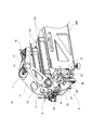
図3は、本実施形態のワーク自動搬送機を示した斜視図であり、特に作業モジュール101との間でワークの受渡しを行う状態が示されている。ワーク自動搬送機10は、作業モジュール101を搭載するベース105の前面部に走行装置3が組み付けられ、走行装置3の上に多関節ロボットアーム1が搭載されている。多関節ロボットアーム1は、図示するような伸びた姿勢によって作業モジュール101の内部にまで入り込み、一方で折り畳まれてコンパクトになった起立状態で搬送空間108内を移動するものである。
走行装置3は、ベース105の前面部に支持板21が取り付けられ、その支持板21には平行に配置されたラック22と2本のレール23とが水平方向に固定されている。走行台25は、レール23に対して摺動可能なスライドが設けられ、レール23に従って横方向への移動が可能になっている。走行台25には走行用モータ26が固定され、回転軸に取り付けられたピニオン27がラック22に噛合している。よって、走行用モータ26が駆動してピニオン27がラック22を転動することにより、走行台25がレール23に沿ってベース13の前面部を移動することが可能になる。
次に、走行台25の上には、旋回テーブル18を介して多関節ロボットアーム1が搭載されている。多関節ロボットアーム1は、旋回テーブル18に固定された支持台19に対し、第1関節13を介して上腕部材11が連結され、更に上腕部材11には、第2関節14を介して前腕部材12が連結されている。多関節ロボットアーム1は、第1関節13と第2関節14の各々の関節用モータの回転制御により、上腕部材11と前腕部材12の各々の角度調整が行われ、図示するような伸びた状態と、後述するように折り畳まれた状態との形態変化が可能になっている。
多関節ロボットアーム1は、折り畳まれた前腕部材12が上腕部材11の中に収まるよう構成されている。そのため上腕部材11は、左右一対の上腕プレートが背面プレートによって一体になり、内側に収納空間を備えるように断面がコの字形に形成されたものである。前腕部材12は、その収納空間側に第2関節14を介して連結された左右一対の平行な前腕プレートによって構成され、自由端側つまり多関節ロボットアーム1の先端部にロボットハンド15が組み付けられている。ロボットハンド15は、第1及び第2関節13,14の回転軸と平行な回転軸によって、前腕部材12に対して回転可能に軸着され、表裏両面にはワークを把持するための油圧チャックが構成されている。
更に、本実施形態のワーク自動搬送機10は、走行台25の上にワークを反転させる反転装置5が搭載されている。その反転装置5は、旋回テーブル18に固定された多関節ロボットアーム1の支持台19に対して組み付けられている。反転装置5は、一対の把持爪17が把持用シリンダによって開閉してワークを掴むことができるように構成されたものである。また、反転装置5には、圧縮エアを作動流体として回転を発生させる回転アクチュエータが設けられ、把持爪17によってクランプしたワークを、鉛直な回転軸を中心にして180°回転させることができるようになっている。
次に、ワーク自動搬送機10は、多関節ロボットアーム1や走行装置3など駆動を制御するための制御装置7が備えられている。図4は、ワーク自動搬送機10の制御システムを簡略化して示したブロック図である。制御装置7は、CPU31のほかにROM32やRAM43、不揮発性メモリ34といった記憶装置などを備えたコンピュータを主体とするものであり、I/035を介して多関節ロボットアーム1、走行装置3、反転装置5の各駆動部に接続されている。
加工機械ライン100では、各々の作業モジュール101に制御装置が搭載され、詳しく図示しないが、そうした作業機側の制御装置とワーク自動搬送機10の制御装置7が集線装置を介して接続されたLANが構築されている。また、作業モジュール101には、図1などに示すように、タッチパネル式やボタン式の入力手段を有し、作業情報や操作画面などの表示や作業者による設定値の入力などが可能な操作表示装置107が設けられ、各制御装置に対してLANによって接続されている。よって、操作表示装置107から、ワーク自動搬送機10の制御に対する数値入力などが可能になっている。
ワーク自動搬送機10の制御装置7には、複数の作業モジュール101に対するワークの搬送ルートや、多関節ロボットアーム1の受渡し姿勢などを制御する搬送プログラムなどがメモリに格納されている。特に、本実施形態では、反転装置5にワークを受渡しする際、ワークのサイズに応じて多関節ロボットアーム1の姿勢制御を行う姿勢制御プログラム341が格納されている。操作表示装置107からは、多関節ロボットアーム1に対して姿勢制御を行うための数値、すなわちワーク寸法などの入力が行われる。
続いて、ワーク自動搬送機10は、加工機械ライン100の搬送空間108の中を多関節ロボットアーム1が移動し、図3に示すように変形して作業モジュール101の内部にまで入り込み、ワークの受渡しが行われる。そして、2台の旋盤によってワークの両面に段階的な加工が行われる場合には、多関節ロボットアーム1のロボットハンド15から反転装置5にワークが受渡しされ、把持爪17が回転してワークの向きが180°反転した後、再びロボットハンド15に戻される。
前記課題の欄でも述べたように、これまでは上腕部材11の姿勢(角度)を一定にし、前腕部材12の折り畳み角度を調節することにより反転装置5とのワークの受渡しが行われていた。図5は、そうした多関節ロボットアーム1に対する従来の姿勢制御を示した図である。上腕部材11の一定角度の姿勢は、第1関節13と第2関節14との両回転軸を結んだ上腕軸41がほぼ鉛直になるように設定されていた。そして、第2関節とロボットハンド15との両回転軸を結んだ前腕軸42の操作角度θn(θ1,θ2)が、ワークW(W1,W2)のサイズに応じて調整されていた。
図5に示すAパターンとBパターンでは、多関節ロボットアーム1が、厚さTn(T1,T2)の異なるワークW1,W2を反転装置5へ受渡しする状態が示されている。反転装置5を定位置とした場合には、ワークWのサイズに応じてロボットハンド15の受渡し位置を変化させる必要が生じる。反転装置5におけるワークWnの受取りは、把持爪17がワークWnの厚さTnの中央部分を把持するようにして行われる。そうした場合、サイズの異なるワークW1,W2において、前腕軸42の操作角度θ1,θ2と、第1関節13とロボットハンド15の回転軸(ワークWnの中心)との距離(受渡し高さ)Hn(H1,H2)に関して違いが生じた。
ワークWnのサイズの違いがロボットハンド15の受渡し位置の違いとなるが、これまでは前腕軸42の操作角度θnを調整することによって対応していた。また、操作角度θnだけの調整では受渡し高さHnの違いが大きくなりすぎてしまい、ロボットハンド15と反転装置5との間で適切な受渡しが不可能な場合もある。よって、取り扱うワークWnのサイズが変わった場合には、作業者は反転装置5の取り付け高さを調整する段取り替えを行う必要があった。そのため、これまでは受渡しミスが生じ得ること、また確実な受渡しには反転装置5の段取り替えが必要であることなどの問題があった。
この点、本実施形態では、操作表示装置107からワークサイズ(任意の厚さTxの数値)が入力されることにより、姿勢制御プログラム341に従って上腕軸41の操作角度θnと、その上腕軸41に対する前腕軸42の操作角度θnが算出され、各々の適切な数値に基づいた多関節ロボットアーム1の姿勢制御が行われる。図6は、多関節ロボットアーム1に対する本実施形態の姿勢制御を示した図である。
姿勢制御を実行する姿勢制御プログラム341では、上腕軸41と前腕軸42の操作角度θnの組み合わせにより、反転装置5の把持爪17がワークWnを同じ状態で把持できるようにした制御が行われる。ここで、反転装置5によるワークWの同じ把持状態とは、従来と同様に把持爪17がワークWnを厚さTnの中央部分で把持することと、更に第1関節13とロボットハンド15の回転軸(ワークWnの中心)との距離(受渡し高さ)Hxが一定になることである。受渡し高さHxを一定にすることにより、常に把持爪17がワークWnの中心部分を把持することになるからである。
そこで、図6に例では、サイズが大きいワークW1の場合、鉛直な基準線40に対する上腕軸41の操作角度θ32が、サイズの小さいワークW2の場合の上腕部材41の操作角度θ42より大きな前傾姿勢となった。そして、ワークW1の場合の上腕軸41に対する前腕軸42の操作角度θ31は、ワークW2の場合の操作角度θ41より小さくなった。こうした各々の操作角度θnの調整によって、ワークサイズが異なる場合であっても、受渡し高さHxが常に一定になる。
そのため、実施形態のワーク自動搬送機10では、加工機械ライン100で行われるワークWnの加工に際し、作業者が操作表示装置107からワークサイズTnを入力することにより、多関節ロボットアーム1と反転装置5との安定したワークの受渡しや反転装置5の段取り替えを不要にすることができる。
ところで、ワーク自動搬送機10では、反転装置5によるワークWの反転のほかに、ロボットハンド15の反転や多関節ロボットアーム1の旋回などの作業動作も行われる。しかし、多関節ロボット1の上腕軸41が傾くことにより、その操作角度θnの大きさによっては狭い搬送空間108を構成する前カバー103などに、前述した動作の際に動作にロボットハンド15や多関節ロボットアーム1が干渉してしまうことになる。
そこで、搬送空間108の大きさを基に動作可能な上腕軸41の傾斜角範囲θdnが設定されている。よって、傾斜角範囲θdn内で上腕軸41が傾斜した場合には、そのままロボットハンド15の反転や多関節ロボットアーム1の旋回などの動作が行われる。一方で、傾斜角範囲θdnを超えて上腕部材11が傾いた姿勢でワークWの受渡しが行われた場合は、その上腕軸41を鉛直に、或いは傾斜角範囲θdn内に収まるように起立させて多関節ロボットアーム1が干渉しないようにする。
以上、本発明の一実施形態について説明したが、本発明はこれらに限定されるものではなく、その趣旨を逸脱しない範囲で様々な変更が可能である。
例えば、ワーク自動搬送機10や加工機械ライン100は一例であって、それぞれ異なる構成であってもよい。
例えば、ワーク自動搬送機10や加工機械ライン100は一例であって、それぞれ異なる構成であってもよい。
1…多関節ロボットアーム 3…走行装置 5…反転装置 7…制御装置 10…ワーク自動搬送機 11…上腕部材 12…前腕部材 13…第1関節 14…第2関節 15…ロボットハンド 17…把持爪 40…基準線 41…上腕軸 43…前腕軸 100…加工機械ライン 101…作業モジュール 108…搬送空間 341…姿勢制御プログラム
Claims (3)
- ガイドレールに沿って移動可能な走行台と、
前記走行台に搭載され、支持部材に対して第1関節によって回転支持された第1アーム部材、前記第1アーム部材に対して第2関節によって回転支持された第2アーム部材および、前記第2アーム部材に取り付けられたロボットハンドを備える多関節ロボットアームと、
前記走行台に搭載され、前記多関節ロボットアームとの間でワークの受渡しを行う反転装置と、
前記反転装置にワークを受渡しする際、ワークのサイズに応じて前記第1アーム部材と前記第2アーム部材との角度調整によって、前記多関節ロボットアームの姿勢制御を行う制御装置と、
を有するワーク自動搬送機。 - ワークのサイズを入力する入力装置を有し、前記制御装置は、前記入力装置によって入力された数値から前記第1アーム部材と前記第2アーム部材との角度を算出して前記多関節ロボットアームの姿勢制御を行う請求項1に記載のワーク自動搬送機。
- 前記多関節ロボットアームと前記反転装置は旋回装置を介して前記走行台に搭載され、前記制御装置は、前記旋回装置の駆動に応じて前記多関節ロボットアームの姿勢制御を行う請求項1又は請求項2に記載のワーク自動搬送機。
Priority Applications (3)
| Application Number | Priority Date | Filing Date | Title |
|---|---|---|---|
| PCT/JP2018/027617 WO2020021615A1 (ja) | 2018-07-24 | 2018-07-24 | ワーク自動搬送機 |
| JP2020531857A JP7041747B2 (ja) | 2018-07-24 | 2018-07-24 | ワーク自動搬送機 |
| CN201880095838.XA CN112469533A (zh) | 2018-07-24 | 2018-07-24 | 工件自动输送机 |
Applications Claiming Priority (1)
| Application Number | Priority Date | Filing Date | Title |
|---|---|---|---|
| PCT/JP2018/027617 WO2020021615A1 (ja) | 2018-07-24 | 2018-07-24 | ワーク自動搬送機 |
Publications (1)
| Publication Number | Publication Date |
|---|---|
| WO2020021615A1 true WO2020021615A1 (ja) | 2020-01-30 |
Family
ID=69181519
Family Applications (1)
| Application Number | Title | Priority Date | Filing Date |
|---|---|---|---|
| PCT/JP2018/027617 Ceased WO2020021615A1 (ja) | 2018-07-24 | 2018-07-24 | ワーク自動搬送機 |
Country Status (3)
| Country | Link |
|---|---|
| JP (1) | JP7041747B2 (ja) |
| CN (1) | CN112469533A (ja) |
| WO (1) | WO2020021615A1 (ja) |
Citations (4)
| Publication number | Priority date | Publication date | Assignee | Title |
|---|---|---|---|---|
| JPH06328139A (ja) * | 1993-05-25 | 1994-11-29 | Nisshinbo Ind Inc | 板材折曲げ加工機用のロボット |
| JPH0911164A (ja) * | 1995-06-30 | 1997-01-14 | Amada Co Ltd | ベンディング用6軸垂直多関節型ロボット |
| WO2015145576A1 (ja) * | 2014-03-25 | 2015-10-01 | 富士機械製造株式会社 | 多関節ロボットアーム |
| JP2018001393A (ja) * | 2016-07-08 | 2018-01-11 | キヤノン株式会社 | ロボット装置、ロボット制御方法、プログラム及び記録媒体 |
Family Cites Families (3)
| Publication number | Priority date | Publication date | Assignee | Title |
|---|---|---|---|---|
| WO2015145575A1 (ja) * | 2014-03-25 | 2015-10-01 | 富士機械製造株式会社 | ワーク自動搬送機 |
| JP6504864B2 (ja) * | 2015-03-13 | 2019-04-24 | キヤノン株式会社 | ロボット制御方法、ロボット装置、プログラム、記録媒体及び物品の製造方法 |
| WO2017042878A1 (ja) * | 2015-09-08 | 2017-03-16 | 富士機械製造株式会社 | 多関節ロボットアーム |
-
2018
- 2018-07-24 JP JP2020531857A patent/JP7041747B2/ja active Active
- 2018-07-24 CN CN201880095838.XA patent/CN112469533A/zh active Pending
- 2018-07-24 WO PCT/JP2018/027617 patent/WO2020021615A1/ja not_active Ceased
Patent Citations (4)
| Publication number | Priority date | Publication date | Assignee | Title |
|---|---|---|---|---|
| JPH06328139A (ja) * | 1993-05-25 | 1994-11-29 | Nisshinbo Ind Inc | 板材折曲げ加工機用のロボット |
| JPH0911164A (ja) * | 1995-06-30 | 1997-01-14 | Amada Co Ltd | ベンディング用6軸垂直多関節型ロボット |
| WO2015145576A1 (ja) * | 2014-03-25 | 2015-10-01 | 富士機械製造株式会社 | 多関節ロボットアーム |
| JP2018001393A (ja) * | 2016-07-08 | 2018-01-11 | キヤノン株式会社 | ロボット装置、ロボット制御方法、プログラム及び記録媒体 |
Also Published As
| Publication number | Publication date |
|---|---|
| JPWO2020021615A1 (ja) | 2021-05-13 |
| CN112469533A (zh) | 2021-03-09 |
| JP7041747B2 (ja) | 2022-03-24 |
Similar Documents
| Publication | Publication Date | Title |
|---|---|---|
| JP6619560B2 (ja) | 曲げ加工装置 | |
| JP6438937B2 (ja) | 多関節ロボットアーム | |
| JP7364478B2 (ja) | 工作機械 | |
| KR20170098892A (ko) | 생산 시스템 | |
| JP2008260120A (ja) | 取扱マニピュレータ装置 | |
| JP2010036285A (ja) | ロボットにより工作機械へワークの着脱を行うロボットシステム | |
| CN110545952B (zh) | 机器人系统和具备该机器人系统的工作线 | |
| JP7042925B2 (ja) | ワーク自動搬送機 | |
| JP2021020258A (ja) | 搬送ロボット及び工作物搬送装置 | |
| JP6415591B2 (ja) | オートローダ | |
| JP6517782B2 (ja) | ワーク自動搬送機 | |
| JP7041747B2 (ja) | ワーク自動搬送機 | |
| JP7031129B2 (ja) | 搬送システム | |
| JP7400300B2 (ja) | 搬送装置と工作機械 | |
| JP2017047507A (ja) | 工作機械の搬送装置 | |
| JP6728373B2 (ja) | ワーク自動搬送機 | |
| JP2024027359A (ja) | 搬送装置 | |
| JP4350820B2 (ja) | 搬送装置 | |
| JPWO2017042878A1 (ja) | 多関節ロボットアーム | |
| JPH0717447U (ja) | ガントリローダ | |
| JP3099197B2 (ja) | 工作機械におけるワーク受け渡し装置 | |
| CN114364495B (zh) | 多关节机器人、多关节机器人的控制方法及多关节机器人的控制程序 | |
| JP6661031B2 (ja) | 多関節ロボットアーム | |
| JP6741544B2 (ja) | ロボット | |
| JPH065073Y2 (ja) | ワークの倒立移載装置 |
Legal Events
| Date | Code | Title | Description |
|---|---|---|---|
| 121 | Ep: the epo has been informed by wipo that ep was designated in this application |
Ref document number: 18928040 Country of ref document: EP Kind code of ref document: A1 |
|
| ENP | Entry into the national phase |
Ref document number: 2020531857 Country of ref document: JP Kind code of ref document: A |
|
| NENP | Non-entry into the national phase |
Ref country code: DE |
|
| 122 | Ep: pct application non-entry in european phase |
Ref document number: 18928040 Country of ref document: EP Kind code of ref document: A1 |