WO2020012947A1 - 空気入りタイヤ - Google Patents
空気入りタイヤ Download PDFInfo
- Publication number
- WO2020012947A1 WO2020012947A1 PCT/JP2019/025076 JP2019025076W WO2020012947A1 WO 2020012947 A1 WO2020012947 A1 WO 2020012947A1 JP 2019025076 W JP2019025076 W JP 2019025076W WO 2020012947 A1 WO2020012947 A1 WO 2020012947A1
- Authority
- WO
- WIPO (PCT)
- Prior art keywords
- groove
- tire
- circumferential
- lug
- main groove
- Prior art date
- Legal status (The legal status is an assumption and is not a legal conclusion. Google has not performed a legal analysis and makes no representation as to the accuracy of the status listed.)
- Ceased
Links
Images

Classifications
-
- B—PERFORMING OPERATIONS; TRANSPORTING
- B60—VEHICLES IN GENERAL
- B60C—VEHICLE TYRES; TYRE INFLATION; TYRE CHANGING; CONNECTING VALVES TO INFLATABLE ELASTIC BODIES IN GENERAL; DEVICES OR ARRANGEMENTS RELATED TO TYRES
- B60C11/00—Tyre tread bands; Tread patterns; Anti-skid inserts
- B60C11/03—Tread patterns
- B60C11/0304—Asymmetric patterns
-
- B—PERFORMING OPERATIONS; TRANSPORTING
- B60—VEHICLES IN GENERAL
- B60C—VEHICLE TYRES; TYRE INFLATION; TYRE CHANGING; CONNECTING VALVES TO INFLATABLE ELASTIC BODIES IN GENERAL; DEVICES OR ARRANGEMENTS RELATED TO TYRES
- B60C11/00—Tyre tread bands; Tread patterns; Anti-skid inserts
- B60C11/03—Tread patterns
-
- B—PERFORMING OPERATIONS; TRANSPORTING
- B60—VEHICLES IN GENERAL
- B60C—VEHICLE TYRES; TYRE INFLATION; TYRE CHANGING; CONNECTING VALVES TO INFLATABLE ELASTIC BODIES IN GENERAL; DEVICES OR ARRANGEMENTS RELATED TO TYRES
- B60C11/00—Tyre tread bands; Tread patterns; Anti-skid inserts
- B60C11/03—Tread patterns
- B60C11/12—Tread patterns characterised by the use of narrow slits or incisions, e.g. sipes
- B60C11/1236—Tread patterns characterised by the use of narrow slits or incisions, e.g. sipes with special arrangements in the tread pattern
-
- B—PERFORMING OPERATIONS; TRANSPORTING
- B60—VEHICLES IN GENERAL
- B60C—VEHICLE TYRES; TYRE INFLATION; TYRE CHANGING; CONNECTING VALVES TO INFLATABLE ELASTIC BODIES IN GENERAL; DEVICES OR ARRANGEMENTS RELATED TO TYRES
- B60C11/00—Tyre tread bands; Tread patterns; Anti-skid inserts
- B60C11/03—Tread patterns
- B60C11/12—Tread patterns characterised by the use of narrow slits or incisions, e.g. sipes
- B60C11/1259—Depth of the sipe
- B60C11/1263—Depth of the sipe different within the same sipe
-
- B—PERFORMING OPERATIONS; TRANSPORTING
- B60—VEHICLES IN GENERAL
- B60C—VEHICLE TYRES; TYRE INFLATION; TYRE CHANGING; CONNECTING VALVES TO INFLATABLE ELASTIC BODIES IN GENERAL; DEVICES OR ARRANGEMENTS RELATED TO TYRES
- B60C11/00—Tyre tread bands; Tread patterns; Anti-skid inserts
- B60C11/03—Tread patterns
- B60C2011/0337—Tread patterns characterised by particular design features of the pattern
- B60C2011/0339—Grooves
- B60C2011/0341—Circumferential grooves
- B60C2011/0348—Narrow grooves, i.e. having a width of less than 4 mm
-
- B—PERFORMING OPERATIONS; TRANSPORTING
- B60—VEHICLES IN GENERAL
- B60C—VEHICLE TYRES; TYRE INFLATION; TYRE CHANGING; CONNECTING VALVES TO INFLATABLE ELASTIC BODIES IN GENERAL; DEVICES OR ARRANGEMENTS RELATED TO TYRES
- B60C11/00—Tyre tread bands; Tread patterns; Anti-skid inserts
- B60C11/03—Tread patterns
- B60C2011/0337—Tread patterns characterised by particular design features of the pattern
- B60C2011/0339—Grooves
- B60C2011/0358—Lateral grooves, i.e. having an angle of 45 to 90 degees to the equatorial plane
- B60C2011/0372—Lateral grooves, i.e. having an angle of 45 to 90 degees to the equatorial plane with particular inclination angles
-
- B—PERFORMING OPERATIONS; TRANSPORTING
- B60—VEHICLES IN GENERAL
- B60C—VEHICLE TYRES; TYRE INFLATION; TYRE CHANGING; CONNECTING VALVES TO INFLATABLE ELASTIC BODIES IN GENERAL; DEVICES OR ARRANGEMENTS RELATED TO TYRES
- B60C11/00—Tyre tread bands; Tread patterns; Anti-skid inserts
- B60C11/03—Tread patterns
- B60C2011/0337—Tread patterns characterised by particular design features of the pattern
- B60C2011/0339—Grooves
- B60C2011/0381—Blind or isolated grooves
-
- B—PERFORMING OPERATIONS; TRANSPORTING
- B60—VEHICLES IN GENERAL
- B60C—VEHICLE TYRES; TYRE INFLATION; TYRE CHANGING; CONNECTING VALVES TO INFLATABLE ELASTIC BODIES IN GENERAL; DEVICES OR ARRANGEMENTS RELATED TO TYRES
- B60C11/00—Tyre tread bands; Tread patterns; Anti-skid inserts
- B60C11/03—Tread patterns
- B60C2011/0337—Tread patterns characterised by particular design features of the pattern
- B60C2011/0339—Grooves
- B60C2011/0381—Blind or isolated grooves
- B60C2011/0383—Blind or isolated grooves at the centre of the tread
-
- B—PERFORMING OPERATIONS; TRANSPORTING
- B60—VEHICLES IN GENERAL
- B60C—VEHICLE TYRES; TYRE INFLATION; TYRE CHANGING; CONNECTING VALVES TO INFLATABLE ELASTIC BODIES IN GENERAL; DEVICES OR ARRANGEMENTS RELATED TO TYRES
- B60C11/00—Tyre tread bands; Tread patterns; Anti-skid inserts
- B60C11/03—Tread patterns
- B60C2011/0337—Tread patterns characterised by particular design features of the pattern
- B60C2011/0386—Continuous ribs
- B60C2011/0388—Continuous ribs provided at the equatorial plane
-
- B—PERFORMING OPERATIONS; TRANSPORTING
- B60—VEHICLES IN GENERAL
- B60C—VEHICLE TYRES; TYRE INFLATION; TYRE CHANGING; CONNECTING VALVES TO INFLATABLE ELASTIC BODIES IN GENERAL; DEVICES OR ARRANGEMENTS RELATED TO TYRES
- B60C11/00—Tyre tread bands; Tread patterns; Anti-skid inserts
- B60C11/03—Tread patterns
- B60C2011/0337—Tread patterns characterised by particular design features of the pattern
- B60C2011/0386—Continuous ribs
- B60C2011/0393—Narrow ribs, i.e. having a rib width of less than 8 mm
- B60C2011/0395—Narrow ribs, i.e. having a rib width of less than 8 mm for linking shoulder blocks
Definitions
- the present invention relates to a pneumatic tire.
- noise performance In order to improve the wet performance of a pneumatic tire, it is known that, in addition to a main groove extending in a tire circumferential direction, a lug groove extending in a tire width direction is provided on a tread surface of the tire to ensure drainage. .
- the volume of the lug grooves is large, there is a problem that the pumping noise generated at the time of kicking becomes large and the performance of reducing tire noise (hereinafter referred to as noise performance) is deteriorated.
- one end is connected to the main groove and the other end is closed in the land area, drainage can be secured to some extent, and noise performance is lower than that in which both ends of the lug groove are connected to the main groove. It is thought that deterioration can be suppressed. However, there is a need to improve tire noise performance at a higher level.
- An object of the present invention is to provide a pneumatic tire in which noise performance is improved as compared with the conventional tire while suppressing a decrease in wet performance.
- One embodiment of the present invention is a pneumatic tire including a tread pattern on a tread portion.
- the tread pattern has at least three circumferential main grooves extending in the tire circumferential direction at intervals from each other,
- the tire is provided in an area of a shoulder land portion where the first circumferential main groove located on the outermost side in the tire width direction among the circumferential main grooves is located on the outer side in the tire width direction and the ground contact end in the tire width direction is located.
- a plurality of shoulder lug grooves extending from the outer side in the width direction toward the first circumferential main groove, closing without reaching the first circumferential main groove, and arranged at intervals in the tire circumferential direction;
- the first circumferential main groove, and a second circumferential main groove located closest to the first circumferential main groove inside the first circumferential main groove in the tire width direction among the at least three circumferential main grooves. Closed without reaching the first circumferential main groove, being provided in the region of the intermediate land between the circumferential main groove and extending from the second circumferential main groove toward the first circumferential main groove.
- a plurality of first intermediate lug grooves arranged at intervals in the tire circumferential direction;
- a plurality of inner lug grooves spaced in the direction It is provided in the area of the intermediate land portion, extends from the first circumferential main groove toward the second circumferential main groove, closes without reaching the second circumferential main groove, and is spaced in the tire circumferential direction.
- a plurality of second intermediate lug grooves arranged with Including the closed end of the shoulder lug groove, the main groove side portion of the shoulder lug groove located on the first circumferential main groove side extends obliquely with respect to the tire width direction,
- the direction from one of the first intermediate lug grooves and the inner lug grooves toward the other in the tire width direction is a direction from the one of the main groove side portions toward the other in the tire width direction with respect to the tire width direction.
- Is inclined to the same side as the inclined side From the closed end of each of the shoulder lug grooves, each of the shoulder lug grooves is smoothly extended along the inclination direction of the main groove side portion to a plurality of extension lines extending toward each of the closed ends of the inner lug grooves.
- the first intermediate lug grooves overlap
- the second intermediate lug groove extends in a direction along the extension line between two extension lines adjacent in the tire circumferential direction among the extension lines.
- All of the shoulder lug grooves and the inner lug grooves form ends in the extending direction of any of the extension lines, All of the first intermediate lug grooves overlap any of the extensions, It is preferable that all of the second intermediate lug grooves extend between any two of the two extension lines adjacent in the tire circumferential direction.
- the range of the first intermediate lug groove along the tire circumferential direction, the range of the inner lug groove along the tire circumferential direction, and the range of the second intermediate lug groove along the tire circumferential direction do not overlap each other. Is preferred.
- the range of the first intermediate lug groove along the tire circumferential direction does not overlap with the range of the shoulder lug groove along the tire circumferential direction.
- a length along the tire circumferential direction between two connection positions where two first middle lug grooves adjacent to each other in the tire circumferential direction of the first middle lug grooves are connected to the second circumferential main groove is L1.
- the circumferential position of the end of the second intermediate lug groove on the side of the first circumferential main groove is 50 to 95% of the length L1 from one of the connection positions. Is preferably within the range.
- the first circumferential lug of the second intermediate lug groove is L1. It is preferable that the position of the end on the side of the groove in the tire circumferential direction is within a range of 30% of the length L2 about the midpoint in the tire circumferential direction between the closed ends.
- a lug groove overlapping with the extension and connected to the first circumferential main groove is not provided in the intermediate land portion.
- a lug groove overlapping with the extension and connected to the second circumferential main groove is not provided in the area of the inner land portion.
- the intermediate land portion area and the inner land portion area are not provided with a circumferential narrow groove which is narrower than the circumferential main groove and extends in the tire circumferential direction.
- the two extension lines adjacent in the tire circumferential direction do not overlap in the tire circumferential direction.
- the first side in the tire width direction where the first circumferential main groove is located with respect to the tire equator line may be mounted to be outside the vehicle when the pneumatic tire is mounted on the vehicle. preferable.
- the tread pattern is further provided on a second side opposite to the first side in the tire width direction where the first circumferential main groove is located with respect to the tire equator line, and the third circumferential main groove is provided.
- a fourth circumferential main groove located outside the groove in the tire width direction and extending in the tire circumferential direction;
- the intermediate land portion is referred to as a first intermediate land portion
- a second intermediate land portion is located between the third circumferential main groove and the fourth circumferential main groove, and in a region of the second intermediate land portion, It is preferable that a circumferential narrow groove extending in the tire circumferential direction and having a narrower groove width than the circumferential main groove is provided.
- the tread pattern further comprises: It is provided in the area of the second intermediate land portion, extends from the fourth circumferential main groove toward the circumferential narrow groove, closes without reaching the circumferential narrow groove, and is spaced apart in the tire circumferential direction.
- a plurality of third intermediate lug grooves arranged The closed end of each of the third intermediate lug grooves is provided in the region of the second intermediate land portion and connects the narrow circumferential groove of the region of the second intermediate land portion with an interval in the tire circumferential direction.
- a plurality of sipes arranged.
- the third intermediate lug groove and the sipe that are connected to each other, as a sipe lug groove, A first sipe lug groove that bends and extends so that the extension direction of the third intermediate lug groove is different from the extension direction of the sipe; It is preferable to include a second sipe lug groove that extends linearly so that the extending direction of the third intermediate lug groove and the extending direction of the sipe coincide with each other.
- the range of the third intermediate lug groove along the tire circumferential direction does not overlap with the range of the inner lug groove along the tire circumferential direction.
- FIG. 2 is a diagram illustrating an example of a tread pattern of the tire of FIG. 1. It is a figure explaining an extension. It is a figure explaining an arrangement position of a lug groove along a tire peripheral direction. It is a figure explaining an arrangement position of an extension along a tire peripheral direction. It is a figure explaining an arrangement position of a lug groove along a tire peripheral direction. It is a figure explaining an arrangement position of a lug groove along a tire peripheral direction. It is a figure explaining an arrangement position of a lug groove along a tire peripheral direction. It is a figure explaining an arrangement position of a lug groove along a tire peripheral direction.
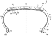
- FIG. 1 is a tire cross-sectional view illustrating an example of a profile cross-section of a tire 10.
- the tire 10 is, for example, a passenger car tire. Passenger car tires are tires defined in Chapter A of JATMA YEAR BOOK 2012 (standards of the Japan Automobile Tire Association).
- the tire 10 can be applied to a light truck tire defined in Chapter B and a truck and bus tire defined in Chapter C.
- the tire width direction is a direction parallel to the rotation axis of the tire.
- the outer side in the tire width direction is a side apart from the tire center line CL (tire equator line) representing the tire equatorial plane in the tire width direction.
- the inner side in the tire width direction is a side approaching the tire center line CL in the tire width direction.
- the tire circumferential direction is a direction in which the tire rotates around the rotation axis of the tire.
- the tire radial direction is a direction orthogonal to the rotation axis of the tire.
- the outer side in the tire radial direction refers to a side away from the rotation axis.
- the inner side in the tire radial direction refers to a side approaching the rotation axis.
- the tire 10 includes a tread portion 10T having a tread pattern, a pair of bead portions 10B, and a pair of side portions 10S provided on both sides of the tread portion 10T and connected to the pair of bead portions 10B and the tread portion 10T.
- the tire 10 has a carcass ply 12, a belt 14, and a bead core 16 as a skeleton material, and around these skeleton materials, a tread rubber member 18, a side rubber member 20, a bead filler rubber member 22, It mainly has a rim cushion rubber member 24 and an inner liner rubber member 26.
- the carcass ply 12 is formed of a carcass ply material formed by winding between a pair of annular bead cores 16 to form a toroidal shape and covering organic fibers with rubber.
- the carcass ply 12 is wound around the bead core 16 and extends outward in the tire radial direction.
- a belt 14 composed of two belt members 14a and 14b is provided outside the carcass ply 12 in the tire radial direction.
- the belt 14 is made of a member in which rubber is coated on a steel cord that is arranged at a predetermined angle, for example, 20 to 30 degrees with respect to the tire circumferential direction, and the lower belt material 14a becomes the upper belt material 14b.
- the width in the tire width direction is longer than that.
- the inclination directions of the steel cords of the two layers of belt members 14a and 14b are opposite to each other. For this reason, the belt members 14a and 14b form an intersecting layer and suppress the expansion of the carcass ply 12 due to the filled air pressure.
- a tread rubber member 18 is provided outside the belt 14 in the tire radial direction, and side rubber members 20 are connected to both ends of the tread rubber member 18 to form side portions 10S.
- a rim cushion rubber member 24 is provided at an inner end of the side rubber member 20 in the tire radial direction, and comes into contact with a rim on which the tire 10 is mounted. Outside the bead core 16 in the tire radial direction, a portion of the carcass ply 12 before being wound around the bead core 16 and a portion of the carcass ply 12 wound around the bead core 16 are sandwiched.
- a bead filler rubber member 22 is provided outside the bead core 16 in the tire radial direction.
- An inner liner rubber member 26 is provided on an inner surface of the tire 10 facing an air-filled tire cavity region surrounded by the tire 10 and the rim.
- a two-layer belt cover 30, which covers the belt 14 from the tire radial outside of the belt 14 and is covered with organic fibers by rubber.
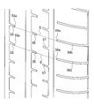
- FIG. 2 is a diagram showing a part of a tread pattern of the tire 10 of FIG. 1 developed on a plane.
- the tread pattern of the example shown in FIG. 2 includes main grooves (circumferential main grooves) 21, 23, 25, and 27 extending in the tire circumferential direction.
- the main groove refers to a groove having a groove depth of, for example, 6.5 to 9.0 mm and a groove width of, for example, 5.0 to 15.0 mm.
- the number of circumferential main grooves provided in the tread pattern may be three, four, five, or the like.
- the tread pattern of the example shown in FIG. 2 further includes narrow grooves (circumferential narrow grooves) 31 and 33 extending in the tire circumferential direction.
- the narrow grooves 31, 33 are narrow grooves having a narrower groove width and a shallower groove depth than the main grooves 21, 23, 25, 27.
- a narrow groove means a groove having a groove depth of, for example, 1.0 to 5.0 mm and a groove width of, for example, 0.8 to 3.0 mm.
- the narrow groove 31 is provided in a region located outside the main groove 21 in the tire width direction.
- the narrow groove 33 is provided in a region between the main grooves 21 and 23.
- the tread pattern of the example shown in FIG. 2 further includes lug grooves 51, 53, 55, 57, 58, and 59.
- the lug groove 51 (third intermediate lug groove) extends from the main groove 21 (fourth circumferential main groove) to the main groove 21 and the narrow groove 33 in the region of the second intermediate land portion between the main grooves 21 and 23. Are closed in the region 71A without extending to the main groove 21 in the tire width direction in the region 71A.
- the lug groove 53 (inner lug groove) extends from the main groove 23 (third circumferential main groove) in the inner land area 73 between the main grooves 23 and 25 in the tire width direction and reaches the main groove 25. Without closing, it is closed in the area 73.
- the tire center line CL is located in the region 73.
- the lug groove 55 (first intermediate lug groove) extends from the main groove 25 (second circumferential main groove) in the region 75 of the first intermediate land portion between the main grooves 25 and 27 in the tire width direction and extends in the tire width direction. It does not reach the groove 27 and is closed in the region 75.
- the lug groove 57 (second intermediate lug groove) extends in the tire width direction from the main groove 27 (first circumferential main groove) in the tire width direction and does not reach the main groove 25 and is closed in the region 75. .
- the extending direction of the lug grooves 51, 53, 55, 57 and the main groove 21 are located at the connection positions with the main grooves 21, 23, 25, 27. , 23, 25, 27 with respect to the extending direction, the smaller land portion of the land portion is chamfered (chamfered).
- the lug groove 58 (hereinafter referred to as the shoulder lug groove 58) extends in the tire width direction from the outside in the tire width direction toward the main groove 21 in the shoulder land portion area 77A located outside the narrow groove 31 in the tire width direction. , Does not reach the main groove 21 and is closed in the region 77 ⁇ / b> B between the narrow groove 31 and the main groove 21.
- the lug groove 59 (hereinafter, referred to as a shoulder lug groove 59) extends in the tire width direction from the outside in the tire width direction to the main groove 27 in the shoulder land portion region 79 located outside the main groove 27 in the tire width direction. Without reaching the main groove 27.
- the grounding ends in the tire width direction are located in the regions 77B and 79.
- the grounding ends are both ends in the tire width direction of the grounding surface when the tire 10 is mounted on a normal rim, filled with a normal internal pressure, and grounded on a horizontal surface under the condition that the load is 88% of the normal load.
- the regular rim refers to a “measurement rim” specified by JATMA, a “Design Rim” specified by TRA, or a “Measuring Rim” specified by ETRTO.
- the normal internal pressure refers to the “maximum air pressure” specified by JATMA, the maximum value of “TIRE LOAD LIMITS AT VARIOUS COLD INFLATION PRESSURES” specified by TRA, or “INFLATION PRESSURES” specified by ETRTO.
- the normal load refers to the “maximum load capacity” specified by JATMA, the maximum value of “TIRE LOAD LIMITS AT VARIOUS COLD INFLATION PRESSURES” specified by TRA, or “LOAD CAPACITY” specified by ETRTO.
- a plurality of these lug grooves 51, 53, 55, 57, 58, 59 are provided at intervals in the tire circumferential direction.
- the groove depth of the lug grooves is shallower than the groove depths of the main grooves 21, 23, 25, 27 and deeper than the groove depths of the narrow grooves 31, 33.
- the lug groove is a groove having a groove depth of, for example, 2.0 to 7.5 mm and a groove width of, for example, 1.5 to 7.5 mm.
- wet performance A decrease in steering stability (hereinafter referred to as wet performance) can be suppressed.
- one of the two ends in the extending direction is not connected to the main groove from the viewpoint of reducing the tire noise in the lug grooves 51, 53, 55, and 57. .
- the shoulder lug grooves 58 and 59 are not connected to the main grooves 27 and 21 from the viewpoint of reducing tire noise because the groove volumes are large.
- the groove located outside the vehicle mounting (the side indicated by “OUT” in FIG. 2) with respect to the tire center line CL is inside the vehicle mounting (“IN” in FIG. 2).
- the shoulder lug groove 59 is not connected to the main groove 27 because the noise performance is more likely to be affected as compared with the groove located on the side shown in FIG.
- the shoulder lug grooves 58, 59 include the closed ends 58a, 59a of the shoulder lug grooves 58, 59, and the main groove side portions 58b, 59b located on the circumferential main grooves 21, 27 side of the grounding end E are tires. It extends obliquely to the width direction. The direction from one of the lug grooves 51, 53, 55, 57 to the other in the tire width direction is one of the main groove side portions 58b, 59b of the shoulder lug grooves 58, 59 with respect to the tire width direction. From the other side to the other side (the "first side” or the "second side” shown in FIG. 2).
- the tread pattern of the example shown in FIG. 2 further includes a sipe 61.
- the sipe 61 connects the closed end 51a of the lug groove 51 and the narrow groove 33, and extends in the tire width direction in the region 71A.
- the sipe 61 forms sipe lug grooves 40 and 41 described later together with the lag groove 51.
- a plurality of sipes 61 are provided at intervals in the tire circumferential direction. Since the lug grooves 40 and 41 with sipes are provided with the sipes 61, the groove volume is reduced as compared with the case where the main groove 21 and the narrow groove 33 are connected by lug grooves, and the generation of pumping noise is suppressed. . For this reason, the noise performance is improved.
- a sipe has a sipe depth of, for example, 2.0 to 7.5 mm and a sipe width of, for example, 0.3 to 1.0 mm.
- the lug grooves 55 overlap a plurality of extension lines S as in the example shown in FIG.
- the lug groove 57 (hereinafter, referred to as a second intermediate lug groove 57) extends in a direction along the extension line S between two extension lines S adjacent in the tire circumferential direction among the plurality of extension lines S. ing.
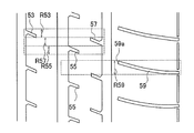
- FIG. 3 is a diagram for explaining the extension line S, and shows two extension lines S as representatives.
- the extension line S extends from the closed end 79a of each of the plurality of shoulder lug grooves 59 to each of the plurality of shoulder lug grooves 59 smoothly along the inclination direction of the main groove side portion 59b.
- the extension line S is a straight line.
- the term “smoothly extending” means that the oblique direction of the shoulder lug groove 59 and the inner lug groove 53 with respect to the tire width direction and the extending direction of the extension line S at the closed ends 59 a and 53 a of the shoulder lug groove 59 and the inner lug groove 53. It means that the smaller one of the formed angles is 10 degrees or less, preferably 5 degrees or less.
- the smaller one of the angles formed by the inclination direction of the inner lug groove 53 and the inclination direction of the extension line S is preferably 10 degrees or less, more preferably 5 degrees or less.
- first intermediate lug groove 55 overlaps with the extension line S means that the first intermediate lug groove 55 is in contact with or intersects with the extension line S, or that the first intermediate lug groove 55 is orthogonal to the extension line S from the extension line S.
- first intermediate lug groove 55 is in contact with or intersects with a region that is twice as long as the groove width of the first intermediate lug groove 55.
- second intermediate lug groove 57 extends in the direction along the extension line S means that the inclination angle of the extension direction of the second intermediate lug groove 57 with respect to the extension line S is within 10 degrees.
- the shoulder lug groove 59, the first intermediate lug groove 55, and the inner lug groove 53 are located so as to overlap with the extension line S inclined with respect to the tire width direction, the shoulder lug groove 59, the first lug groove 59, The intermediate lug groove 55 and the inner lug groove 53 are easily dispersed and arranged in the tire circumferential direction, and when kicked out from the road surface, pumping sounds are generated from the respective lug grooves 59, 55, 53 at different timings. For this reason, tire noise is reduced as compared with the case where pumping sounds are simultaneously generated from many lug grooves at the time of kicking. That is, the noise performance is improved.
- the second intermediate lug groove 57 is disposed closer to the shoulder lug groove 59 than the inner lug groove 53 and the first intermediate lug groove 55. For this reason, the second intermediate lug groove 57 is disposed so as to extend along the extension line S between two extension lines S adjacent in the tire circumferential direction, so that the extension line S does not overlap.
- the shoulder lug groove 59 has a large groove volume and generates a large pumping noise, and therefore it is desirable that the second intermediate lug groove 57 and the shoulder lug groove 59 be separated in the tire circumferential direction.
- all of the shoulder lug grooves 59 and the inner lug grooves 53 form ends in the extending direction of any one of the plurality of extended lines S, and the first intermediate lug grooves 55 It is preferable that all of them overlap with any one of the extension lines S, and that all of the second intermediate lug grooves 57 extend between any one of the two extension lines S adjacent in the tire circumferential direction. Accordingly, the effect that the inner lug groove 53, the first intermediate lug groove 55, the second intermediate lug groove 57, and the shoulder lug groove 59 are dispersedly arranged at different positions in the tire circumferential direction is different from the entire circumference in the tire circumferential direction. And the effect of improving noise performance is increased.
- the pitch length is different from the pitch length of the other areas. If the interval between the lug grooves adjacent in the circumferential direction is different from the interval between the lug grooves adjacent in the tire circumferential direction in other regions, it is difficult to obtain such a form.
- the lug groove which overlaps the extension line S and is connected to the first circumferential main groove 27 is not provided in the region 75 of the first intermediate land portion. According to one embodiment, it is preferred that the lug groove which overlaps with the extension line S and is connected to the second circumferential main groove 25 is not provided in the inner land area 73. When such lug grooves are provided, it is difficult to obtain the effect of distributing the lug grooves in the tire circumferential direction.
- no lug groove connected to the main groove 25 or the main groove 27 is provided in the region 75 of the first intermediate lug groove.
- the lug groove connected to the main groove 23 or the main groove 25 is not provided in the inner land area 73 except for the inner lug groove 53.
- no lug grooves are provided in the shoulder land area 79 except for the shoulder lug grooves 59.
- FIG. 4 is a diagram illustrating the arrangement positions of the lug grooves 53, 55, and 57 along the tire circumferential direction. As described above, the first intermediate lug groove 55, the inner lug groove 53, and the second intermediate lug groove 57 are dispersedly arranged at different positions in the tire circumferential direction, so that tire noise is effectively reduced. You.
- the range R55 of the first intermediate lug groove 55 along the tire circumferential direction does not overlap with the range R59 of the shoulder lug groove 59 along the tire circumferential direction. Is preferred. Since the first intermediate lug groove 55 and the shoulder lug groove 59 are arranged at different positions in the tire circumferential direction as described above, tire noise is effectively reduced.
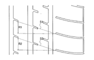
- FIG. 5 is a diagram illustrating the arrangement position of the extension line S along the tire circumferential direction.
- the inner lug groove 53, the first intermediate lug groove 55, the second intermediate lug groove 57, and the shoulder lug groove 59 are formed.
- the effect of dispersing and arranging in the tire circumferential direction is difficult to obtain.
- the magnitude of the inclination angle of the extension line S with respect to the tire width direction is preferably 10 to 30 degrees.
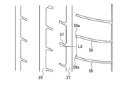
- first intermediate lug grooves 55 two first intermediate lug grooves 55 adjacent to each other in the tire circumferential direction are connected to the second circumferential main groove 25.
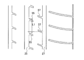
- the position of the end of the second intermediate lug groove 57 on the side of the first circumferential main groove 27 in the tire circumferential direction is the two connection positions described above. It is preferably within a range of 50 to 95% of the length L1, and more preferably within a range of 70 to 90% of the length L1 from the connection position of one of them (the first side in FIG. 6).
- connection position refers to a connection position of the first intermediate lug groove 55 having the closed end within the range in the tire circumferential direction between the two connection positions and the first circumferential main groove 25.
- FIG. 7 is a diagram illustrating the positional relationship between the shoulder lug groove 59 and the second intermediate lug groove 57 along the tire circumferential direction.
- the intermediate point means the midpoint of the line connecting the adjacent closed ends 59a.
- connection position of the second intermediate lug groove 57 with the first circumferential main groove 27 does not include the above-described chamfered portion.
- the first intermediate land portion region 75 and the inner land portion region 73 have circumferential narrow portions extending in the tire circumferential direction, the groove width being narrower than the circumferential main grooves 21, 23, 25, 27.
- no groove is provided.
- the shoulder land portion region 79 is also not provided with the circumferential narrow groove.
- the first side in the tire width direction where the first circumferential main groove 27 is located with respect to the tire center line CL is located outside the vehicle when the tire 10 is mounted on the vehicle. It is preferred to be attached to the. Since the first circumferential main groove 27 is located on the outside of the vehicle, which has a large influence on the noise performance, the effect of reducing the tire noise is increased.
- the tread pattern preferably further includes a fourth circumferential groove 21 and a circumferential narrow groove 33, as in the example shown in FIG.
- the fourth circumferential main groove 41 is provided on the second side opposite to the first side in the tire width direction where the first circumferential main groove 27 is located with respect to the tire center line CL. It is located outside the direction main groove 23 in the tire width direction.
- the circumferential narrow groove 33 is provided in a region of the second intermediate land portion. Since the narrow groove 33 is provided on the inside of the vehicle, which has a small effect on the noise performance, the wet performance is effectively improved without lowering the noise performance.
- a circumferential narrow groove 31 is further provided in a shoulder land portion located outside the main groove 21 in the tire width direction. This increases the effect of improving the wet performance without lowering the noise performance.
- the number of circumferential narrow grooves provided on the second side may be one, three, four, or the like.
- the lengths of the third intermediate lug groove 51, the inner lug groove 53, the first intermediate lug groove 55, and the second intermediate lug groove 57 along the tire width direction are the lug grooves 51, 53. , 55, and 57 are preferably 20 to 50% of the length (width) in the tire width direction of each of the second intermediate land portion, the inner land portion, and the first intermediate land portion. , 30 to 40%.
- the length of some lug grooves is Preferably, the length of the other lug groove is longer than the length of the other lug groove (for example, 115 to 125% of the length of the other lug groove), and the lengths of the other lug grooves are equal to each other.
- the length of the third intermediate lug groove 51 along the tire width direction is preferably 30 to 80% of the length (width) of the region 71A in the tire width direction.
- the inclination angles of the inner lug groove 53, the first intermediate lug groove 55, and the second intermediate lug groove 57 with respect to the tire width direction are preferably substantially equal.
- the phrase “substantially equal” means that the difference between the lug grooves in the inclination angle is at most 10 degrees, preferably at most 5 degrees.
- the tread pattern further has the lug groove with a sipe described above, as in the example shown in FIG. It is preferable that the plurality of lug grooves with sipes have a first lug groove 40 with sipes and a second lug groove 41 with sipes described below.
- the first sipe lug groove 40 is bent and extends so that the extending direction of the lug groove 51 and the extending direction of the sipe 61 are different, and is provided at least one in the region 71A.
- edge components extending in various directions are formed on the tread surface. Therefore, the steering stability particularly on a wet low ⁇ road surface (water depth of 1 to 3 mm) tends to be improved.
- the first sipe lug groove 40 extends in a curved manner, the difference between the extending direction of the lug groove 51 and the extending direction of the sipe 61 is that the lug groove 51 is closed at the closed end 51 a of the lug groove 51. This means that the extending direction and the extending direction of the sipe 61 are different.
- the second lug groove 41 with a sipe extends linearly so that the extending direction of the lug groove 51 and the extending direction of the sipe 61 coincide with each other, and at least one second lug groove 41 is provided in the region 71A.
- the block in the area 71A easily falls down during turning, and easily deforms following the road surface. For this reason, adhesion friction between the tread surface and the road surface is increased, and the steering stability particularly on a wet road surface during turning is easily improved.
- a plurality of blocks defined by the main groove 21, the narrow groove 33, and two lug grooves with sipes adjacent in the tire circumferential direction are arranged in the tire circumferential direction.
- the steering stability on a wet road surface (hereinafter referred to as wet performance) is various.
- the first lug groove 40 with a sipe and the second lug groove 41 with a second sipe are provided in the tread pattern based on the finding that the tread pattern improves in a well-balanced manner.
- the bending angle of the lug groove 51 and the sipe 61 for distinguishing the first sipe lug groove 40 and the second sipe lug groove 41 (of the angle formed by the extending direction of the lug groove 51 and the extending direction of the sipe 61)
- the smaller angle is, for example, in the range of 1 to 5 degrees. If the bending angle of the sipe-attached lug groove is equal to or larger than the above-described distinguished bending angle, it corresponds to the first sipe-attached lug groove 40; This corresponds to 41.
- the first sipe lug groove 40 has a plurality of types of sipe lug grooves having different bending angles. As a result, edge components extending in various directions are created, which contributes to an improvement in wet performance.
- each of the first lug groove 40 with sipe and the second lug groove 41 with second sipe is preferably arranged so as to form a pair adjacent in the tire circumferential direction.
- the ratio of the number of the first sipe lug grooves 40 to the number of the second sipe lug grooves 41 in the region 71A is preferably 1 to 5. If the ratio is less than 1, the number of the second sipe lug grooves 41 may be too small, and the effect of improving the wet performance due to the ease of the block falling may not be sufficiently obtained. If the ratio exceeds 5, the number of the first sipe lug grooves 40 may be too small, and the effect of improving the wet performance by the edge component may not be sufficiently obtained.
- the ratio is preferably 1.2 to 3.
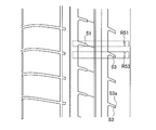
- the range R51 of the third intermediate lug groove 51 along the tire circumferential direction does not overlap with the range R53 of the inner lug groove 53 along the tire circumferential direction.
- FIG. 8 is a diagram illustrating the positional relationship between the third intermediate lug groove 51 and the inner lug groove 53 along the tire circumferential direction.
- the range R51 of the third intermediate lug groove 51 along the tire circumferential direction further does not overlap with the range of the shoulder lug groove 58 along the tire circumferential direction.
- the third intermediate lug groove 51 extends from the connection position of the inner lug groove 53 with the third circumferential main groove 23 in the tire width direction along the inclination direction of the inner lug groove 53 with respect to the tire width direction. It is preferable to overlap with a virtual straight line (second extension line) extending outward (inside of the vehicle in FIG. 2).
- the third intermediate lug groove 51 overlapping with the second extended line means that the third intermediate lug groove 51 is in contact with or intersects with the second extended line, or from the second extended line.
- a mode in which the third intermediate lug groove 51 is in contact with or intersects with a region separated by a length twice as long as the groove width of the third intermediate lug groove 51 in a direction perpendicular to the second extension line is also included.
- the region 71 ⁇ / b> B is not provided with a lug groove or a sipe connected to the narrow groove 33 or the main groove 23, and a continuous rib is formed in the tire circumferential direction.
- the region 77B no lug grooves and sipes connected to the narrow grooves 31 or the main grooves 21 are provided, and ribs continuous in the tire circumferential direction are formed.
- a large edge component extending in the tire circumferential direction is formed by the two narrow grooves 31 and 33, and the rigidity of the two ribs is secured.
- the length (width) of the region 77B in the tire width direction is wider than the width of the region 71B.
- the tread pattern of the present embodiment is not limited to the tread pattern of the example shown in FIG.
- Tables 1 and 2 show the forms relating to the tread pattern of each tire and the evaluation results.
- “the overlap of the first intermediate lug groove, the inner lug groove, and the second intermediate lug groove”, “the overlap of the first intermediate lug groove and the shoulder lug groove”, and “the third intermediate lug groove and the inner side”””Overlap with lug grooves” means the overlap between the lug groove ranges along the tire circumferential direction, respectively.
- the “first side narrow groove” means a narrow groove provided in a land area of at least one of the first intermediate lug groove and the inner lug groove.
- “none” means that only the lug groove 51 was provided without providing the sipe 61.
- connection position of the second intermediate lug groove and the main groove and L1 means that the connection position of the second intermediate lug groove and the first circumferential main groove is such that the two first intermediate lug grooves are adjacent to each other in the tire circumferential direction.
- the lug groove means the percentage of L1 in the tire circumferential direction from the connection position on the first side of the two connection positions connected to the second circumferential main groove.
- “Relationship between L2 of the connection position of the second intermediate lug groove and the main groove” means that the connection position of the second intermediate lug groove with the first circumferential main groove is two shoulder lug grooves adjacent in the tire circumferential direction.
- Comparative Example 1 in the tread pattern of Example 1, the position of the inner lug groove in the tire circumferential direction is shifted in the region 73 so that the range of the inner lug groove along the tire circumferential direction overlaps with the range of the first intermediate lug groove.
- the first intermediate lug groove is changed so as not to overlap the imaginary line connecting the closed end of the shoulder lug groove and the inner lug groove.
- the inclination angle of the main groove side portion of the shoulder lug groove was adjusted so that the extension line smoothly extended from the closed end of the shoulder lug groove.
- the second intermediate lug groove was provided at a position overlapping the extension line.
- the third intermediate lug groove is extended from the connection position of the inner lug groove to the main groove 23 to the outer side in the tire width direction (inward of the vehicle) along the inclination direction of the inner lug groove with respect to the tire width direction. It was arranged so as not to overlap with the second extension line. Further, in the first embodiment, in the tread pattern shown in FIG. 2, the circumferential narrow grooves of the second intermediate land portion and the shoulder land portion on the second side (the inside of the vehicle) are omitted. Further, in the second intermediate land portion, a sipe connected to the third intermediate lug groove was omitted.
- Example 2 in the tread pattern of Example 1, the inclination angle of the extension line with respect to the tire width direction was set to 10 degrees, and the ranges of the first intermediate lug groove and the inner lug groove along the tire circumferential direction were changed. In Comparative Example 2, Example 1, and Examples 3 to 8, the inclination angle of the extension line with respect to the tire width direction was 25 degrees.
- the fourth embodiment in the tread pattern of the first embodiment, in the region of the first intermediate land portion, a circumferential narrow portion is provided between the closed end of the first intermediate lug groove and the closed end of the second intermediate lug groove in the tire width direction. A groove was provided.
- Example 5 the tire having the tread pattern of Example 1 was mounted on a test vehicle with the vehicle mounting direction reversed from that of Example 1.
- a total of two circumferential narrow grooves are arranged on each of the second intermediate land portion and the shoulder land portion on the second side (the inside of the vehicle).
- a sipe for connecting the third intermediate lug groove and the circumferential narrow groove is further provided in a region of the second intermediate land portion. That is, a lug groove with a sipe was provided in the region of the second intermediate land portion.
- the plurality of sipe lug grooves have the first sipe lug grooves and the second sipe lug grooves described above, and the number of the first sipe lug grooves corresponds to the number of the second sipe lug grooves. The ratio was 2.
- the bending angle of the second sipe-with-sipe lug was two types, 2 degrees and 3 degrees. Further, the first lug groove with a sipe and the second lug groove with a sipe having the same bending angle are arranged so as to form the pair. In Example 8, in the tread pattern of Example 7, the third intermediate lug groove was further arranged to overlap the second extension line.
- test tire was mounted on a wheel having a rim size of 17 ⁇ 7J and mounted on a front wheel drive vehicle having a displacement of 2400 cc, and the air pressure was set to 230 kPa.
- wet performance A road surface sprinkled at a water depth of 1 to 2 mm is provided in some sections, and the other sections are run on an asphalt road surface sprinkled at a depth of less than 1 mm at a speed of 40 to 100 km / h.
- a sensory evaluation was conducted on the steering performance during change and cornering, and the stability during straight running.
- the wet performance is indicated by an index with Comparative Example 1 as a conventional tire taken as 100, and the larger the index is, the better the wet performance is.
- the first intermediate lug groove overlaps the extension line, and the second intermediate lug groove extends along the extension line between adjacent extension lines. It can be seen that the noise performance is improved as compared with the conventional one while suppressing the decrease in the wet performance. From a comparison between Example 1 and Example 2, it can be seen that the noise performance is improved by the absence of overlapping of the first intermediate lug groove, the inner lug groove, and the second intermediate lug groove along the tire circumferential direction. From the comparison between Example 1 and Example 3, it can be seen that the relationship between the connection position of the second intermediate lug groove with the first circumferential main groove and L1 or L2 satisfies the relationship described in the above embodiment, and thus the noise performance is improved. It can be seen that is improved. From a comparison between Example 1 and Example 4, it can be seen that the noise performance is improved by not providing the tire circumferential narrow groove in the area of the inner land portion or the first intermediate land portion.
- Example 1 From a comparison between Example 1 and Example 5, it can be seen that the noise performance is improved when the first side is disposed outside the vehicle. From the comparison between Example 1 and Example 6, it is found that the provision of the narrow groove in the second intermediate land portion improves the wet performance. A comparison between Example 6 and Example 7 shows that the provision of the lug grooves with sipes improves the wet performance. From the comparison between Example 7 and Example 8, it can be seen that the noise performance is improved by the absence of the overlap of the third intermediate lug groove and the inner lug groove along the tire circumferential direction.
- the pneumatic tire of the present invention has been described in detail.
- the pneumatic tire of the present invention is not limited to the above embodiments or examples, and various improvements and changes may be made without departing from the gist of the present invention. Of course, you can.
Landscapes
- Engineering & Computer Science (AREA)
- Mechanical Engineering (AREA)
- Tires In General (AREA)
Abstract
空気入りタイヤのトレッドパターンにおいて、第1周方向主溝側に位置するショルダーラグ溝の主溝側部分は、タイヤ幅方向に対して傾斜して延びている。第1中間ラグ溝及び内側ラグ溝それぞれのタイヤ幅方向の一方から他方に向かう方向は、タイヤ幅方向に対して、主溝側部分のタイヤ幅方向の一方から他方に向かう方向が傾斜する側と同じ側に傾斜している。ショルダーラグ溝それぞれの閉塞端からショルダーラグ溝それぞれを、主溝側部分の傾斜方向に沿って滑らかに延長して内側ラグ溝の閉塞端のそれぞれに向かって延びる複数の延長線に対して、第1中間ラグ溝は重なっている。第2中間ラグ溝は、延長線のうちタイヤ周方向に隣り合う2本の延長線の間を、延長線に沿った方向に延びている。
Description
本発明は、空気入りタイヤに関する。
空気入りタイヤのウェット性能を向上させるために、タイヤのトレッド面に、タイヤ周方向に延びる主溝のほかに、タイヤ幅方向に延びるラグ溝を設けて排水性を確保することが知られている。ところが、ラグ溝の溝体積が大きいと、蹴り出し時に発生するポンピング音が大きくなり、タイヤ騒音を低減する性能(以降、騒音性能という)が悪化するという問題がある。
従来、主溝とラグ溝を形成したタイヤにおいて、ラグ溝の一端を主溝と接続するとともに他端を陸部の領域内で閉塞させたトレッドパターンが知られている(特許文献1参照)。
一端を主溝と接続するとともに他端を陸部の領域内で閉塞させ他ラグ溝によれば、排水性をある程度確保できるとともに、ラグ溝の両端を主溝に接続したものと比べ騒音性能の悪化を抑制できると考えられる。しかし、より高いレベルでタイヤの騒音性能を向上させることが求められている。
本発明は、ウェット性能の低下を抑えつつ、騒音性能を従来に比べて向上させた空気入りタイヤを提供することを目的とする。
本発明の一態様は、トレッド部にトレッドパターンを備える空気入りタイヤである。
前記トレッドパターンは、互いに間隔をあけてタイヤ周方向に延びる少なくとも3本の周方向主溝と、
前記周方向主溝のうちタイヤ幅方向の最も外側に位置する第1周方向主溝のタイヤ幅方向外側に位置し、タイヤ幅方向の接地端が位置するショルダー陸部の領域に設けられ、タイヤ幅方向外側から前記第1周方向主溝に向かって延びて前記第1周方向主溝に到達することなく閉塞し、タイヤ周方向に間隔をあけて配置された複数のショルダーラグ溝と、
前記第1周方向主溝と、前記少なくとも3本の周方向主溝のうち、前記第1周方向主溝のタイヤ幅方向内側に前記第1周方向主溝に最も接近して位置する第2周方向主溝との間の中間陸部の領域に設けられ、前記第2周方向主溝から前記第1周方向主溝に向かって延びて前記第1周方向主溝に到達することなく閉塞し、タイヤ周方向に間隔をあけて配置された複数の第1中間ラグ溝と、
前記第2周方向主溝と、前記少なくとも3本の周方向主溝のうち、前記第2周方向主溝に対して前記第1周方向主溝と反対側に位置する第3周方向主溝との間の内側陸部の領域に設けられ、前記第3周方向主溝から前記第2周方向主溝に向かって延びて前記第2周方向主溝に到達することなく閉塞し、タイヤ周方向に間隔をあけて配置された複数の内側ラグ溝と、
前記中間陸部の領域に設けられ、前記第1周方向主溝から前記第2周方向主溝に向かって延びて前記第2周方向主溝に到達することなく閉塞し、タイヤ周方向に間隔をあけて配置された複数の第2中間ラグ溝と、を備え、
前記ショルダーラグ溝の閉塞端を含み、前記第1周方向主溝側に位置する前記ショルダーラグ溝の主溝側部分は、タイヤ幅方向に対して傾斜して延び、
前記第1中間ラグ溝及び前記内側ラグ溝それぞれのタイヤ幅方向の一方から他方に向かう方向は、タイヤ幅方向に対して、前記主溝側部分のタイヤ幅方向の前記一方から前記他方に向かう方向が傾斜する側と同じ側に傾斜し、
前記ショルダーラグ溝それぞれの閉塞端から前記ショルダーラグ溝それぞれを、前記主溝側部分の傾斜方向に沿って滑らかに延長して前記内側ラグ溝の閉塞端のそれぞれに向かって延びる複数の延長線に対して、前記第1中間ラグ溝は重なっており、
前記第2中間ラグ溝は、前記延長線のうちタイヤ周方向に隣り合う2本の延長線の間を、前記延長線に沿った方向に延びている、ことを特徴とする。
前記トレッドパターンは、互いに間隔をあけてタイヤ周方向に延びる少なくとも3本の周方向主溝と、
前記周方向主溝のうちタイヤ幅方向の最も外側に位置する第1周方向主溝のタイヤ幅方向外側に位置し、タイヤ幅方向の接地端が位置するショルダー陸部の領域に設けられ、タイヤ幅方向外側から前記第1周方向主溝に向かって延びて前記第1周方向主溝に到達することなく閉塞し、タイヤ周方向に間隔をあけて配置された複数のショルダーラグ溝と、
前記第1周方向主溝と、前記少なくとも3本の周方向主溝のうち、前記第1周方向主溝のタイヤ幅方向内側に前記第1周方向主溝に最も接近して位置する第2周方向主溝との間の中間陸部の領域に設けられ、前記第2周方向主溝から前記第1周方向主溝に向かって延びて前記第1周方向主溝に到達することなく閉塞し、タイヤ周方向に間隔をあけて配置された複数の第1中間ラグ溝と、
前記第2周方向主溝と、前記少なくとも3本の周方向主溝のうち、前記第2周方向主溝に対して前記第1周方向主溝と反対側に位置する第3周方向主溝との間の内側陸部の領域に設けられ、前記第3周方向主溝から前記第2周方向主溝に向かって延びて前記第2周方向主溝に到達することなく閉塞し、タイヤ周方向に間隔をあけて配置された複数の内側ラグ溝と、
前記中間陸部の領域に設けられ、前記第1周方向主溝から前記第2周方向主溝に向かって延びて前記第2周方向主溝に到達することなく閉塞し、タイヤ周方向に間隔をあけて配置された複数の第2中間ラグ溝と、を備え、
前記ショルダーラグ溝の閉塞端を含み、前記第1周方向主溝側に位置する前記ショルダーラグ溝の主溝側部分は、タイヤ幅方向に対して傾斜して延び、
前記第1中間ラグ溝及び前記内側ラグ溝それぞれのタイヤ幅方向の一方から他方に向かう方向は、タイヤ幅方向に対して、前記主溝側部分のタイヤ幅方向の前記一方から前記他方に向かう方向が傾斜する側と同じ側に傾斜し、
前記ショルダーラグ溝それぞれの閉塞端から前記ショルダーラグ溝それぞれを、前記主溝側部分の傾斜方向に沿って滑らかに延長して前記内側ラグ溝の閉塞端のそれぞれに向かって延びる複数の延長線に対して、前記第1中間ラグ溝は重なっており、
前記第2中間ラグ溝は、前記延長線のうちタイヤ周方向に隣り合う2本の延長線の間を、前記延長線に沿った方向に延びている、ことを特徴とする。
前記ショルダーラグ溝及び前記内側ラグ溝のすべてが、前記延長線のうちのいずれかの延長線の延在方向の端をなし、
前記第1中間ラグ溝のすべてが前記延長線のいずれかと重なっており、
前記第2中間ラグ溝のすべてが、タイヤ周方向に隣り合う前記2本の延長線の間のうちいずれかの間を延びていることが好ましい。
前記第1中間ラグ溝のすべてが前記延長線のいずれかと重なっており、
前記第2中間ラグ溝のすべてが、タイヤ周方向に隣り合う前記2本の延長線の間のうちいずれかの間を延びていることが好ましい。
タイヤ周方向に沿った前記第1中間ラグ溝の範囲、タイヤ周方向に沿った前記内側ラグ溝の範囲、及びタイヤ周方向に沿った前記第2中間ラグ溝の範囲は、互いに重なっていないことが好ましい。
タイヤ周方向に沿った前記第1中間ラグ溝の範囲は、タイヤ周方向に沿った前記ショルダーラグ溝の範囲と重なっていないことが好ましい。
前記第1中間ラグ溝のうちタイヤ周方向に隣り合う2つの第1中間ラグ溝それぞれが前記第2周方向主溝に接続する2つの接続位置の間のタイヤ周方向に沿った長さをL1としたとき、前記第2中間ラグ溝の前記第1周方向主溝の側の端のタイヤ周方向の位置は、前記接続位置のうちの一方の接続位置から前記長さL1の50~95%の範囲内にあることが好ましい。
前記ショルダーラグ溝のうちタイヤ周方向に隣り合う2つのショルダーラグ溝の閉塞端の間のタイヤ周方向に沿った長さをL2としたとき、前記第2中間ラグ溝の前記第1周方向主溝の側の端のタイヤ周方向の位置は、当該閉塞端の間のタイヤ周方向における中間点を中心とする前記長さL2の30%の範囲内にあることが好ましい。
前記中間陸部の領域には、前記延長線と重なり前記第1周方向主溝に接続するラグ溝は設けられていないことが好ましい。
前記内側陸部の領域には、前記延長線と重なり前記第2周方向主溝に接続するラグ溝は設けられていないことが好ましい。
前記中間陸部の領域及び前記内側陸部の領域には、前記周方向主溝より溝幅の狭い、タイヤ周方向に延びる周方向細溝は設けられていないことが好ましい。
タイヤ周方向に隣り合う前記2本の延長線のタイヤ周方向の範囲は重なっていないことが好ましい。
タイヤ赤道線に対して、前記第1周方向主溝が位置するタイヤ幅方向の第1の側は、前記空気入りタイヤを車両に装着する時、車両装着外側となるように装着されることが好ましい。
前記トレッドパターンは、さらに、タイヤ赤道線に対して、前記第1周方向主溝が位置するタイヤ幅方向の第1の側と反対側の第2の側に設けられ、前記第3周方向主溝のタイヤ幅方向外側に位置し、タイヤ周方向に延びる第4周方向主溝を備え、
前記中間陸部を第1中間陸部というとき、前記第3周方向主溝と前記第4周方向主溝の間に第2中間陸部が位置し、前記第2中間陸部の領域には、前記周方向主溝より溝幅の狭い、タイヤ周方向に延びる周方向細溝が設けられていることが好ましい。
前記中間陸部を第1中間陸部というとき、前記第3周方向主溝と前記第4周方向主溝の間に第2中間陸部が位置し、前記第2中間陸部の領域には、前記周方向主溝より溝幅の狭い、タイヤ周方向に延びる周方向細溝が設けられていることが好ましい。
前記トレッドパターンは、さらに、
前記第2中間陸部の領域に設けられ、前記第4周方向主溝から前記周方向細溝に向かって延びて前記周方向細溝に到達することなく閉塞し、タイヤ周方向に間隔をあけて配置された複数の第3中間ラグ溝と、
前記第2中間陸部の領域に設けられ、前記第3中間ラグ溝それぞれの閉塞端と前記第2中間陸部の領域の前記周方向細溝とを接続し、タイヤ周方向に間隔をあけて配置された複数のサイプと、を備えることが好ましい。
前記第2中間陸部の領域に設けられ、前記第4周方向主溝から前記周方向細溝に向かって延びて前記周方向細溝に到達することなく閉塞し、タイヤ周方向に間隔をあけて配置された複数の第3中間ラグ溝と、
前記第2中間陸部の領域に設けられ、前記第3中間ラグ溝それぞれの閉塞端と前記第2中間陸部の領域の前記周方向細溝とを接続し、タイヤ周方向に間隔をあけて配置された複数のサイプと、を備えることが好ましい。
互いに接続された前記第3中間ラグ溝及び前記サイプは、サイプ付きラグ溝として、
前記第3中間ラグ溝の延在方向と前記サイプの延在方向とが異なるよう屈曲して延びる第1のサイプ付きラグ溝と、
前記第3中間ラグ溝の延在方向と前記サイプの延在方向とが一致するよう直線状に延びる第2のサイプ付きラグ溝と、を含むことが好ましい。
前記第3中間ラグ溝の延在方向と前記サイプの延在方向とが異なるよう屈曲して延びる第1のサイプ付きラグ溝と、
前記第3中間ラグ溝の延在方向と前記サイプの延在方向とが一致するよう直線状に延びる第2のサイプ付きラグ溝と、を含むことが好ましい。
タイヤ周方向に沿った前記第3中間ラグ溝の範囲は、タイヤ周方向に沿った前記内側ラグ溝の範囲と重なっていないことが好ましい。
本発明によれば、ウェット性能の低下を抑えつつ、騒音性能を従来に比べて向上させた空気入りタイヤが得られる。
(タイヤの全体説明)
以下、本実施形態の空気入りタイヤ(以降、タイヤという)について説明する。本実施形態には、後述する種々の実施形態が含まれる。図1は、タイヤ10のプロファイル断面の一例を示すタイヤ断面図である。
タイヤ10は、例えば乗用車用タイヤである。乗用車用タイヤは、JATMA YEAR BOOK 2012(日本自動車タイヤ協会規格)のA章に定められるタイヤをいう。この他、B章に定められる小型トラック用タイヤおよびC章に定められるトラック及びバス用タイヤに、タイヤ10を適用することもできる。
以下、本実施形態の空気入りタイヤ(以降、タイヤという)について説明する。本実施形態には、後述する種々の実施形態が含まれる。図1は、タイヤ10のプロファイル断面の一例を示すタイヤ断面図である。
タイヤ10は、例えば乗用車用タイヤである。乗用車用タイヤは、JATMA YEAR BOOK 2012(日本自動車タイヤ協会規格)のA章に定められるタイヤをいう。この他、B章に定められる小型トラック用タイヤおよびC章に定められるトラック及びバス用タイヤに、タイヤ10を適用することもできる。
タイヤ幅方向は、タイヤの回転軸と平行な方向である。タイヤ幅方向外側は、タイヤ幅方向において、タイヤ赤道面を表すタイヤセンターラインCL(タイヤ赤道線)から離れる側である。また、タイヤ幅方向内側は、タイヤ幅方向において、タイヤセンターラインCLに近づく側である。タイヤ周方向は、タイヤの回転軸を回転の中心として回転する方向である。タイヤ径方向は、タイヤの回転軸に直交する方向である。タイヤ径方向外側は、前記回転軸から離れる側をいう。また、タイヤ径方向内側は、前記回転軸に近づく側をいう。
(タイヤ構造)
タイヤ10は、トレッドパターンを有するトレッド部10Tと、一対のビード部10Bと、トレッド部10Tの両側に設けられ、一対のビード部10Bとトレッド部10Tに接続される一対のサイド部10Sと、を備える。
タイヤ10は、骨格材として、カーカスプライ12と、ベルト14と、ビードコア16とを有し、これらの骨格材の周りに、トレッドゴム部材18と、サイドゴム部材20と、ビードフィラーゴム部材22と、リムクッションゴム部材24と、インナーライナーゴム部材26と、を主に有する。
タイヤ10は、トレッドパターンを有するトレッド部10Tと、一対のビード部10Bと、トレッド部10Tの両側に設けられ、一対のビード部10Bとトレッド部10Tに接続される一対のサイド部10Sと、を備える。
タイヤ10は、骨格材として、カーカスプライ12と、ベルト14と、ビードコア16とを有し、これらの骨格材の周りに、トレッドゴム部材18と、サイドゴム部材20と、ビードフィラーゴム部材22と、リムクッションゴム部材24と、インナーライナーゴム部材26と、を主に有する。
カーカスプライ12は、一対の円環状のビードコア16の間を巻きまわしてトロイダル形状を成した、有機繊維をゴムで被覆したカーカスプライ材で構成されている。カーカスプライ12は、ビードコア16の周りに巻きまわされてタイヤ径方向外側に延びている。カーカスプライ12のタイヤ径方向外側に2枚のベルト材14a,14bで構成されるベルト14が設けられている。ベルト14は、タイヤ周方向に対して、所定の角度、例えば20~30度傾斜して配されたスチールコードにゴムを被覆した部材で構成され、下層のベルト材14aが上層のベルト材14bに比べてタイヤ幅方向の幅が長い。2層のベルト材14a,14bのスチールコードの傾斜方向は互いに逆方向である。このため、ベルト材14a,14bは、交錯層となっており、充填された空気圧によるカーカスプライ12の膨張を抑制する。
ベルト14のタイヤ径方向外側には、トレッドゴム部材18が設けられ、トレッドゴム部材18の両端部には、サイドゴム部材20が接続されてサイド部10Sを形成している。サイドゴム部材20のタイヤ径方向内側の端には、リムクッションゴム部材24が設けられ、タイヤ10を装着するリムと接触する。ビードコア16のタイヤ径方向外側には、ビードコア16の周りに巻きまわす前のカーカスプライ12の部分と、ビードコア16の周りに巻きまわしたカーカスプライ12の巻きまわした部分との間に挟まれるようにビードフィラーゴム部材22が設けられている。タイヤ10とリムとで囲まれる空気を充填するタイヤ空洞領域に面するタイヤ10の内表面には、インナーライナーゴム部材26が設けられている。
この他に、ベルト材14bとトレッドゴム部材18との間には、ベルト14のタイヤ径方向外側からベルト14を覆う、有機繊維をゴムで被覆した2層のベルトカバー30を備える。
この他に、ベルト材14bとトレッドゴム部材18との間には、ベルト14のタイヤ径方向外側からベルト14を覆う、有機繊維をゴムで被覆した2層のベルトカバー30を備える。
(トレッドパターン)
図2は、図1のタイヤ10のトレッドパターンの一例を平面に展開したものの一部を示す図である。
図2は、図1のタイヤ10のトレッドパターンの一例を平面に展開したものの一部を示す図である。
図2に示す例のトレッドパターンは、タイヤ周方向に延びる主溝(周方向主溝)21,23,25,27を備えている。本明細書において、主溝は、溝深さが、例えば6.5~9.0mmであり、溝幅が、例えば5.0~15.0mmである溝を意味する。
本実施形態において、トレッドパターンに設けられる周方向主溝の数は、3本であってもよく、4本、5本等であってもよい。
本実施形態において、トレッドパターンに設けられる周方向主溝の数は、3本であってもよく、4本、5本等であってもよい。
図2に示す例のトレッドパターンは、さらに、タイヤ周方向に延びる細溝(周方向細溝)31,33を備えている。細溝31,33は、主溝21,23,25,27よりも溝幅が狭く、溝深さが浅い細溝である。本明細書において、細溝は、溝深さが、例えば1.0~5.0mmであり、溝幅が、例えば0.8~3.0mmである溝を意味する。
細溝31は、主溝21のタイヤ幅方向外側に位置する領域内に設けられている。細溝33は、主溝21,23の間の領域内に設けられている。
細溝31は、主溝21のタイヤ幅方向外側に位置する領域内に設けられている。細溝33は、主溝21,23の間の領域内に設けられている。
図2に示す例のトレッドパターンは、さらに、ラグ溝51,53,55,57,58,59を備えている。
ラグ溝51(第3中間ラグ溝)は、主溝21(第4周方向主溝)から、主溝21,23の間の第2中間陸部の領域のうち、主溝21及び細溝33の間の領域71A内をタイヤ幅方向に延びて主溝21に到達することなく、領域71A内で閉塞している。
ラグ溝53(内側ラグ溝)は、主溝23(第3周方向主溝)から、主溝23,25の間の内側陸部の領域73内をタイヤ幅方向に延びて主溝25に到達することなく、領域73内で閉塞している。図2に示す例のトレッドパターンにおいて、タイヤセンターラインCLは領域73内に位置している。
ラグ溝55(第1中間ラグ溝)は、主溝25(第2周方向主溝)から、主溝25,27の間の第1中間陸部の領域75内をタイヤ幅方向に延びて主溝27に到達することなく、領域75内で閉塞している。
ラグ溝57(第2中間ラグ溝)は、主溝27(第1周方向主溝)から領域75をタイヤ幅方向に延びて主溝25に到達することなく、領域75内で閉塞している。
図2に示す例において、ラグ溝51,53,55,57は、主溝21,23,25,27との接続位置において、ラグ溝51,53,55,57の延在方向と主溝21,23,25,27の延在方向とのなす角のうち小さい方の角の陸部の部分が角落とし(面取り)されている。
ラグ溝51(第3中間ラグ溝)は、主溝21(第4周方向主溝)から、主溝21,23の間の第2中間陸部の領域のうち、主溝21及び細溝33の間の領域71A内をタイヤ幅方向に延びて主溝21に到達することなく、領域71A内で閉塞している。
ラグ溝53(内側ラグ溝)は、主溝23(第3周方向主溝)から、主溝23,25の間の内側陸部の領域73内をタイヤ幅方向に延びて主溝25に到達することなく、領域73内で閉塞している。図2に示す例のトレッドパターンにおいて、タイヤセンターラインCLは領域73内に位置している。
ラグ溝55(第1中間ラグ溝)は、主溝25(第2周方向主溝)から、主溝25,27の間の第1中間陸部の領域75内をタイヤ幅方向に延びて主溝27に到達することなく、領域75内で閉塞している。
ラグ溝57(第2中間ラグ溝)は、主溝27(第1周方向主溝)から領域75をタイヤ幅方向に延びて主溝25に到達することなく、領域75内で閉塞している。
図2に示す例において、ラグ溝51,53,55,57は、主溝21,23,25,27との接続位置において、ラグ溝51,53,55,57の延在方向と主溝21,23,25,27の延在方向とのなす角のうち小さい方の角の陸部の部分が角落とし(面取り)されている。
ラグ溝58(以降、ショルダーラグ溝58という)は、細溝31のタイヤ幅方向外側に位置するショルダー陸部の領域77A内を、タイヤ幅方向外側から主溝21に向かってタイヤ幅方向に延び、細溝31と交差し、主溝21に到達することなく、細溝31と主溝21の間の領域77B内で閉塞している。
ラグ溝59(以降、ショルダーラグ溝59という)は、主溝27のタイヤ幅方向外側に位置するショルダー陸部の領域79内を、タイヤ幅方向外側から主溝27に向かってタイヤ幅方向に延びて主溝27に到達することなく、領域79内で閉塞している。
なお、領域77B,79内には、タイヤ幅方向の接地端が位置している。接地端とは、タイヤ10を正規リムに組み付け、正規内圧を充填し、正規荷重の88%を負荷荷重とした条件において水平面に接地させたときの接地面のタイヤ幅方向の両端である。正規リムとは、JATMAに規定される「測定リム」、TRAに規定される「Design Rim」、あるいはETRTOに規定される「Measuring Rim」をいう。正規内圧とは、JATMAに規定される「最高空気圧」、TRAに規定される「TIRE LOAD LIMITS AT VARIOUS COLD INFLATION PRESSURES」の最大値、あるいはETRTOに規定される「INFLATION PRESSURES」をいう。正規荷重とは、JATMAに規定される「最大負荷能力」、TRAに規定される「TIRE LOAD LIMITS AT VARIOUS COLD INFLATION PRESSURES」の最大値、あるいはETRTOに規定される「LOAD CAPACITY」をいう。
ラグ溝59(以降、ショルダーラグ溝59という)は、主溝27のタイヤ幅方向外側に位置するショルダー陸部の領域79内を、タイヤ幅方向外側から主溝27に向かってタイヤ幅方向に延びて主溝27に到達することなく、領域79内で閉塞している。
なお、領域77B,79内には、タイヤ幅方向の接地端が位置している。接地端とは、タイヤ10を正規リムに組み付け、正規内圧を充填し、正規荷重の88%を負荷荷重とした条件において水平面に接地させたときの接地面のタイヤ幅方向の両端である。正規リムとは、JATMAに規定される「測定リム」、TRAに規定される「Design Rim」、あるいはETRTOに規定される「Measuring Rim」をいう。正規内圧とは、JATMAに規定される「最高空気圧」、TRAに規定される「TIRE LOAD LIMITS AT VARIOUS COLD INFLATION PRESSURES」の最大値、あるいはETRTOに規定される「INFLATION PRESSURES」をいう。正規荷重とは、JATMAに規定される「最大負荷能力」、TRAに規定される「TIRE LOAD LIMITS AT VARIOUS COLD INFLATION PRESSURES」の最大値、あるいはETRTOに規定される「LOAD CAPACITY」をいう。
これらのラグ溝51,53,55,57,58,59は、それぞれ、タイヤ周方向に間隔をあけて複数設けられている。
ラグ溝の溝深さは、主溝21,23,25,27の溝深さより浅く、細溝31,33の溝深さより深い。本明細書において、ラグ溝は、溝深さが、例えば2.0~7.5mmであり、溝幅が、例えば1.5~7.5mmである溝である。
ラグ溝の溝深さは、主溝21,23,25,27の溝深さより浅く、細溝31,33の溝深さより深い。本明細書において、ラグ溝は、溝深さが、例えば2.0~7.5mmであり、溝幅が、例えば1.5~7.5mmである溝である。
図2に示す例のトレッドパターンでは、周方向主溝21,23,25,27、及びラグ溝51,53,55,57,59が設けられていることで、排水性が確保され、ウェット路面における操縦安定性(以降、ウェット性能という)の低下を抑制できる。
一方、図2に示す例のトレッドパターンにおいて、ラグ溝51,53,55,57は、タイヤ騒音を低減する観点から、延在方向の両端のうち一方の端は、主溝に接続していない。また、ショルダーラグ溝58,59は、溝体積が大きいため、タイヤ騒音を低減する観点から、主溝27,21に接続していない。特に、タイヤ10を車両に装着する時、タイヤセンターラインCLを基準とした車両装着外側(図2において「OUT」で示す側)に位置する溝は、車両装着内側(図2において「IN」で示す側)に位置する溝と比べ、騒音性能に影響を与えやすいため、ショルダーラグ溝59は主溝27に接続していない。
ショルダーラグ溝58,59は、ショルダーラグ溝58,59の閉塞端58a,59aを含み、かつ、接地端Eの周方向主溝21,27側に位置する主溝側部分58b,59bは、タイヤ幅方向に対して傾斜して延びている。
ラグ溝51,53,55,57それぞれのタイヤ幅方向の一方から他方に向かう方向は、タイヤ幅方向に対して、ショルダーラグ溝58,59の主溝側部分58b,59bのタイヤ幅方向の一方から他方に向かう方向が傾斜する側(図2に示す「第1の側」あるいは「第2の側」)と同じ側に傾斜している。
ラグ溝51,53,55,57それぞれのタイヤ幅方向の一方から他方に向かう方向は、タイヤ幅方向に対して、ショルダーラグ溝58,59の主溝側部分58b,59bのタイヤ幅方向の一方から他方に向かう方向が傾斜する側(図2に示す「第1の側」あるいは「第2の側」)と同じ側に傾斜している。
図2に示す例のトレッドパターンは、さらに、サイプ61を備えている。サイプ61は、ラグ溝51の閉塞端51aと細溝33とを接続し、領域71A内をタイヤ幅方向に延びている。サイプ61は、ラグ溝51とともに後述するサイプ付きラグ溝40,41をなしている。サイプ61は、タイヤ周方向に間隔をあけて複数設けられている。
サイプ付きラグ溝40,41は、サイプ61を備えているため、主溝21と細溝33をラグ溝で接続した場合と比べ、溝体積が低減されており、ポンピング音の発生が抑制される。このため、騒音性能が向上する。本明細書において、サイプとは、サイプ深さが、例えば2.0~7.5mmであり、サイプ幅が、例えば0.3~1.0mmのものをいう。
サイプ付きラグ溝40,41は、サイプ61を備えているため、主溝21と細溝33をラグ溝で接続した場合と比べ、溝体積が低減されており、ポンピング音の発生が抑制される。このため、騒音性能が向上する。本明細書において、サイプとは、サイプ深さが、例えば2.0~7.5mmであり、サイプ幅が、例えば0.3~1.0mmのものをいう。
本実施形態では、図3に示す例のように、ラグ溝55(以降、第1中間ラグ溝55という)は、複数の延長線Sに重なっている。そして、ラグ溝57(以降、第2中間ラグ溝57という)は、複数の延長線Sのうちタイヤ周方向に隣り合う2本の延長線Sの間を、延長線Sに沿った方向に延びている。図3は、延長線Sを説明する図であり、代表して2本の延長線Sを示している。
延長線Sは、複数のショルダーラグ溝59それぞれの閉塞端79aから、複数のショルダーラグ溝59それぞれを、主溝側部分59bの傾斜方向に沿って滑らかに延長して複数のラグ溝53(以降、内側ラグ溝53という)の閉塞端53aのそれぞれに向かって延びる仮想線である。延長線Sは、直線である。滑らかに延長するとは、ショルダーラグ溝59及び内側ラグ溝53の閉塞端59a,53aにおいて、タイヤ幅方向に対するショルダーラグ溝59及び内側ラグ溝53の傾斜方向と、延長線Sの延在方向とのなす角のうち小さい方の角が10度以下、好ましくは5度以下であることを意味する。内側ラグ溝53の閉塞端における、内側ラグ溝53の傾斜方向と、延長線Sの傾斜方向とがなす角のうち小さい方の角は好ましくは10度以下、より好ましくは5度以下である。
第1中間ラグ溝55が延長線Sと重なるとは、第1中間ラグ溝55が、延長線Sと接している、あるいは交差している形態のほか、延長線Sから当該延長線Sと直交する方向に第1中間ラグ溝55の溝幅の2倍の長さ離れた領域と接している、あるいは交差している形態も含む。また、第2中間ラグ溝57が延長線Sに沿った方向に延びるとは、第2中間ラグ溝57の延在方向の延長線Sに対する傾斜角が10度以内であることを意味する。
延長線Sは、複数のショルダーラグ溝59それぞれの閉塞端79aから、複数のショルダーラグ溝59それぞれを、主溝側部分59bの傾斜方向に沿って滑らかに延長して複数のラグ溝53(以降、内側ラグ溝53という)の閉塞端53aのそれぞれに向かって延びる仮想線である。延長線Sは、直線である。滑らかに延長するとは、ショルダーラグ溝59及び内側ラグ溝53の閉塞端59a,53aにおいて、タイヤ幅方向に対するショルダーラグ溝59及び内側ラグ溝53の傾斜方向と、延長線Sの延在方向とのなす角のうち小さい方の角が10度以下、好ましくは5度以下であることを意味する。内側ラグ溝53の閉塞端における、内側ラグ溝53の傾斜方向と、延長線Sの傾斜方向とがなす角のうち小さい方の角は好ましくは10度以下、より好ましくは5度以下である。
第1中間ラグ溝55が延長線Sと重なるとは、第1中間ラグ溝55が、延長線Sと接している、あるいは交差している形態のほか、延長線Sから当該延長線Sと直交する方向に第1中間ラグ溝55の溝幅の2倍の長さ離れた領域と接している、あるいは交差している形態も含む。また、第2中間ラグ溝57が延長線Sに沿った方向に延びるとは、第2中間ラグ溝57の延在方向の延長線Sに対する傾斜角が10度以内であることを意味する。
このようにタイヤ幅方向に対し傾斜した延長線Sと重なるように、ショルダーラグ溝59、第1中間ラグ溝55、及び内側ラグ溝53が位置していることで、ショルダーラグ溝59、第1中間ラグ溝55、及び内側ラグ溝53は、タイヤ周方向に分散して配置されやすく、路面から蹴り出される際に、それぞれのラグ溝59,55,53から異なるタイミングでポンピング音が発生する。このため、蹴り出し時に多くのラグ溝から同時にポンピング音が発生する場合と比べ、タイヤ騒音が低減される。すなわち、騒音性能が向上する。
一方、第2中間ラグ溝57は、内側ラグ溝53及び第1中間ラグ溝55と比べ、ショルダーラグ溝59に接近して配置されている。このため、タイヤ周方向に隣り合う2本の延長線Sの間を延長線Sに沿って延びるよう、第2中間ラグ溝57を配置することで、延長線Sと重ならないようにしている。ショルダーラグ溝59は溝体積が大きく、大きなポンピング音を発生するため、第2中間ラグ溝57とショルダーラグ溝59はタイヤ周方向に離れていることが望ましいためである。
一方、第2中間ラグ溝57は、内側ラグ溝53及び第1中間ラグ溝55と比べ、ショルダーラグ溝59に接近して配置されている。このため、タイヤ周方向に隣り合う2本の延長線Sの間を延長線Sに沿って延びるよう、第2中間ラグ溝57を配置することで、延長線Sと重ならないようにしている。ショルダーラグ溝59は溝体積が大きく、大きなポンピング音を発生するため、第2中間ラグ溝57とショルダーラグ溝59はタイヤ周方向に離れていることが望ましいためである。
一実施形態によれば、ショルダーラグ溝59及び内側ラグ溝53のすべてが、複数の延長線Sのうちのいずれかの延長線Sの延在方向の端をなし、第1中間ラグ溝55のすべてが延長線Sのいずれかと重なっており、第2中間ラグ溝57のすべてが、タイヤ周方向に隣り合う2本の延長線Sの間のうちいずれかの間を延びていることが好ましい。これにより、内側ラグ溝53、第1中間ラグ溝55、第2中間ラグ溝57、及びショルダーラグ溝59が互いにタイヤ周方向の異なる位置に分散して配置される効果がタイヤ周方向の全周にわたり得られ、騒音性能の向上効果が増す。ここで、例えば、内側陸部の領域73、第1中間陸部の領域75、及びショルダー陸部の領域79の一部の領域において、ピッチ長が他の領域のピッチ長と異なることによって、タイヤ周方向に隣り合うラグ溝の間隔が他の領域においてタイヤ周方向に隣り合うラグ溝の間隔と異なっていると、このような形態が得られ難い。
一実施形態によれば、第1中間陸部の領域75には、延長線Sと重なり第1周方向主溝27に接続するラグ溝は設けられていないことが好ましい。また、一実施形態によれば、内側陸部の領域73には、延長線Sと重なり第2周方向主溝25に接続するラグ溝は設けられていないことが好ましい。このようなラグ溝が設けられていると、ラグ溝をタイヤ周方向に分散して配置する効果が得られ難くなる。
好ましくは、第1中間ラグ溝の領域75には、第1中間ラグ溝55及び第2中間ラグ溝57を除いて、主溝25あるいは主溝27に接続するラグ溝は設けられていない。また、好ましくは、内側陸部の領域73には、内側ラグ溝53を除いて、主溝23あるいは主溝25に接続するラグ溝は設けられていない。また、好ましくは、ショルダー陸部の領域79には、ショルダーラグ溝59を除いてラグ溝は設けられていない。
好ましくは、第1中間ラグ溝の領域75には、第1中間ラグ溝55及び第2中間ラグ溝57を除いて、主溝25あるいは主溝27に接続するラグ溝は設けられていない。また、好ましくは、内側陸部の領域73には、内側ラグ溝53を除いて、主溝23あるいは主溝25に接続するラグ溝は設けられていない。また、好ましくは、ショルダー陸部の領域79には、ショルダーラグ溝59を除いてラグ溝は設けられていない。
一実施形態によれば、図4に示すように、タイヤ周方向に沿った第1中間ラグ溝55の範囲R55、タイヤ周方向に沿った内側ラグ溝53の範囲R53、及びタイヤ周方向に沿った第2中間ラグ溝57の範囲R57は、互いに重なっていないことが好ましい。図4は、タイヤ周方向に沿ったラグ溝53,55,57の配置位置を説明する図である。このように、第1中間ラグ溝55、内側ラグ溝53、及び第2中間ラグ溝57がタイヤ周方向の互いに異なる位置に分散して配置されていることで、タイヤ騒音が効果的に低減される。
また、一実施形態によれば、図4に示すように、タイヤ周方向に沿った第1中間ラグ溝55の範囲R55は、タイヤ周方向に沿ったショルダーラグ溝59の範囲R59と重なっていないことが好ましい。このように、第1中間ラグ溝55、及びショルダーラグ溝59がタイヤ周方向の互いに異なる位置に配置されていることで、タイヤ騒音が効果的に低減される。
一実施形態によれば、図5に示すように、タイヤ周方向に隣り合う延長線S1,S2のタイヤ周方向の範囲R1,R2は、重なっていないことが好ましい。図5は、タイヤ周方向に沿った延長線Sの配置位置を説明する図である。タイヤ周方向に沿った2本の延長線S1,S2の範囲R1,R2が重なっていると、内側ラグ溝53、第1中間ラグ溝55、第2中間ラグ溝57、及びショルダーラグ溝59をタイヤ周方向に分散して配置する効果が得られ難い。このため、延長線Sのタイヤ幅方向に対する傾斜角の大きさは、10~30度であることが好ましい。
一実施形態によれば、第1中間ラグ溝55のうちタイヤ周方向に隣り合う2つの第1中間ラグ溝55それぞれが第2周方向主溝25に接続する2つの接続位置の間のタイヤ周方向に沿った長さをL1としたとき、図6に示すように、第2中間ラグ溝57の第1周方向主溝27の側の端のタイヤ周方向の位置は、上記2つの接続位置のうちの一方(図6において第1の側)の接続位置から長さL1の50~95%の範囲内にあることが好ましく、70~90%の範囲内にあることがより好ましい。図6は、タイヤ周方向に沿った第1中間ラグ溝55及び第2中間ラグ溝57の位置関係を説明する図である。これにより、タイヤ騒音を低減する効果は大きくなる。なお、一方の接続位置とは、2つの接続位置の間のタイヤ周方向の範囲内に閉塞端を有する第1中間ラグ溝55の第1周方向主溝25との接続位置をいう。
一実施形態によれば、ショルダーラグ溝59のうちタイヤ周方向に隣り合う2つのショルダーラグ溝59の閉塞端59aの間のタイヤ周方向に沿った長さをL2としたとき、図7に示すように、第2中間ラグ溝57の第1周方向主溝27の側の端のタイヤ周方向の位置は、当該閉塞端59aの間のタイヤ周方向における中間点を中心としてタイヤ周方向に長さL2の30%の範囲内にあることが好ましく、長さL2の20%の範囲内にあることがより好ましい。図7は、タイヤ周方向に沿ったショルダーラグ溝59及び第2中間ラグ溝57の位置関係を説明する図である。これにより、タイヤ騒音を低減する効果は大きくなる。なお、中間点とは、隣り合う閉塞端59aを結ぶ線分の中点を意味する。
以上2つの実施形態において、第2中間ラグ溝57の第1周方向主溝27との接続位置には、上記した角落とし(面取り)された部分は含まれない。
一実施形態によれば、第1中間陸部の領域75及び内側陸部の領域73には、周方向主溝21,23,25,27より溝幅の狭い、タイヤ周方向に延びる周方向細溝は設けられていないことが好ましい。これにより、タイヤ騒音を効果的に低減できる。
好ましくは、ショルダー陸部の領域79にも、上記周方向細溝は設けられていない。
好ましくは、ショルダー陸部の領域79にも、上記周方向細溝は設けられていない。
一実施形態によれば、タイヤセンターラインCLに対して、第1周方向主溝27が位置するタイヤ幅方向の第1の側は、タイヤ10を車両に装着する時、車両装着外側となるように装着されることが好ましい。騒音性能に与える影響の大きい車両装着外側において第1周方向主溝27が位置していることで、上記したタイヤ騒音を低減する効果が大きくなる。
一実施形態によれば、トレッドパターンは、図2に示す例のように、さらに、第4周方向溝21と、周方向細溝33を備えることが好ましい。
第4周方向主溝41は、タイヤセンターラインCLに対して、第1周方向主溝27が位置するタイヤ幅方向の第1の側と反対側の第2の側に設けられ、第3周方向主溝23のタイヤ幅方向外側に位置している。
周方向細溝33は、第2中間陸部の領域に設けられている。騒音性能に与える影響が小さい車両装着内側に細溝33が設けられていることで、騒音性能を低下させることなく、ウェット性能が効果的に向上する。
好ましくは、さらに、主溝21のタイヤ幅方向外側に位置するショルダー陸部の領域に周方向細溝31を備えることが好ましい。これにより、騒音性能を低下させることなく、ウェット性能が向上する効果が増す。
第2の側に設けられる周方向細溝の数は、1本であってもよく、3本、4本等であってもよい。
第4周方向主溝41は、タイヤセンターラインCLに対して、第1周方向主溝27が位置するタイヤ幅方向の第1の側と反対側の第2の側に設けられ、第3周方向主溝23のタイヤ幅方向外側に位置している。
周方向細溝33は、第2中間陸部の領域に設けられている。騒音性能に与える影響が小さい車両装着内側に細溝33が設けられていることで、騒音性能を低下させることなく、ウェット性能が効果的に向上する。
好ましくは、さらに、主溝21のタイヤ幅方向外側に位置するショルダー陸部の領域に周方向細溝31を備えることが好ましい。これにより、騒音性能を低下させることなく、ウェット性能が向上する効果が増す。
第2の側に設けられる周方向細溝の数は、1本であってもよく、3本、4本等であってもよい。
一実施形態によれば、タイヤ幅方向に沿った第3中間ラグ溝51、内側ラグ溝53、第1中間ラグ溝55、及び第2中間ラグ溝57の長さは、当該ラグ溝51,53,55,57が位置する第2中間陸部、内側陸部、第1中間陸部の各領域のタイヤ幅方向長さ(幅)に対して、20~50%の長さであることが好ましく、30~40%であることがより好ましい。また、第3中間ラグ溝51、内側ラグ溝53、第1中間ラグ溝55、及び第2中間ラグ溝57の間で、一部のラグ溝(例えば第3中間ラグ溝51)の長さは、他のラグ溝の長さより長く(他のラグ溝の長さの例えば115~125%の長さ)、当該他のラグ溝の長さは互いに等しいことが好ましい。
なお、タイヤ幅方向に沿った第3中間ラグ溝51の長さは、領域71Aのタイヤ幅方向長さ(幅)に対しては、30~80%の長さであることが好ましい。
なお、タイヤ幅方向に沿った第3中間ラグ溝51の長さは、領域71Aのタイヤ幅方向長さ(幅)に対しては、30~80%の長さであることが好ましい。
また、一実施形態によれば、内側ラグ溝53、第1中間ラグ溝55、及び第2中間ラグ溝57のタイヤ幅方向に対する傾斜角は、略等しいことが好ましい。略等しいとは、上記傾斜角のラグ溝間での相違が最大10度、好ましくは最大5度以内であることをいう。
一実施形態によれば、トレッドパターンは、図2に示す例のように、さらに、上述したサイプ付きラグ溝を有していることが好ましい。複数のサイプ付きラグ溝は、下記説明する、第1のサイプ付きラグ溝40及び第2のサイプ付きラグ溝41、を有していることが好ましい。
第1のサイプ付きラグ溝40は、ラグ溝51の延在方向とサイプ61の延在方向とが異なるよう屈曲して延び、領域71A内に少なくとも1本設けられている。このような形態の第1のサイプ付きラグ溝40を備えることで、種々の方向に延びるエッジ成分がトレッド表面に作られる。このため、特にウェット低μ路面(水深1~3mm)での操縦安定性が向上しやすい。なお、第1のサイプ付きラグ溝40が湾曲して延びている場合、ラグ溝51の延在方向とサイプ61の延在方向が異なるとは、ラグ溝51の閉塞端51aにおいてラグ溝51の延在方向とサイプ61の延在方向が異なることを意味する。
第2のサイプ付きラグ溝41は、ラグ溝51の延在方向とサイプ61の延在方向とが一致するよう直線状に延び、領域71A内に少なくとも1本設けられている。このような形態の第2のサイプ付きラグ溝41を備えることで、旋回時に領域71A内のブロックが倒れ込みやすく、路面に追従して変形しやすくなる。このため、トレッド表面と路面との間の凝着摩擦が大きくなり、特に旋回時におけるウェット路面での操縦安定性が向上しやすい。なお、領域71A内には、主溝21、細溝33、及び、タイヤ周方向に隣り合う2本のサイプ付きラグ溝によって画定された複数のブロックがタイヤ周方向に配列されている。
この実施形態では、第1のサイプ付きラグ溝40と第2のサイプ付きラグ溝41を領域71A内に混在するよう設けることで、ウェット路面における操縦安定性(以降、ウェット性能という)が、種々の局面においてバランスよく向上するという知見に基づき、トレッドパターンに、第1のサイプ付きラグ溝40と第2のサイプ付きラグ溝41を設けている。
第1のサイプ付きラグ溝40と第2のサイプ付きラグ溝41とを区別するラグ溝51とサイプ61の屈曲角度(ラグ溝51の延在方向とサイプ61の延在方向がなす角のうち小さい方の角度)は、例えば、1~5度の範囲内にある。サイプ付きラグ溝の屈曲角度が、上記区別する屈曲角度以上である場合は、第1のサイプ付きラグ溝40に該当し、上記区別する屈曲角度未満である場合は、第2のサイプ付きラグ溝41に該当する。
一実施形態によれば、第1のサイプ付きラグ溝40は、屈曲角度が異なる複数の種類のサイプ付きラグ溝を有していることが好ましい。これにより、多様な方向に延びるエッジ成分が作られ、ウェット性能の向上に寄与する。
一実施形態によれば、第1のサイプ付きラグ溝40、及び、第2のサイプ付きラグ溝41のそれぞれは、タイヤ周方向に隣り合った対をなすよう配置されていることが好ましい。これにより、第1のサイプ付きラグ溝40によって作られるエッジ成分による効果、及び、第2のサイプ付きラグ溝41によって得られるブロックの倒れ込み易さによる効果が、それぞれ強調され、ウェット性能がバランスよく向上する効果が増す。
一実施形態によれば、領域71Aにおける、第2のサイプ付きラグ溝41の数に対する第1のサイプ付きラグ溝40の数の比は1~5であることが好ましい。上記比が1未満であると、第2のサイプ付きラグ溝41の数が少なすぎて、ブロックの倒れ込み易さによるウェット性能の向上効果が十分に得られない場合がある。上記比が5を超えると、第1のサイプ付きラグ溝40の数が少なすぎて、エッジ成分によるウェット性能の向上効果が十分に得られない場合がある。上記比は、好ましくは1.2~3である。
一実施形態によれば、図8に示すように、タイヤ周方向に沿った第3中間ラグ溝51の範囲R51は、タイヤ周方向に沿った内側ラグ溝53の範囲R53と重なっていないことが好ましい。図8は、タイヤ周方向に沿った第3中間ラグ溝51及び内側ラグ溝53の位置関係を説明する図である。このように、第3中間ラグ溝51、及び内側ラグ溝53がタイヤ周方向の互いに異なる位置に配置されていることで、タイヤ騒音が効果的に低減される。
好ましくは、タイヤ周方向に沿った第3中間ラグ溝51の範囲R51は、さらに、タイヤ周方向に沿ったショルダーラグ溝58の範囲と重なっていないことが好ましい
好ましくは、タイヤ周方向に沿った第3中間ラグ溝51の範囲R51は、さらに、タイヤ周方向に沿ったショルダーラグ溝58の範囲と重なっていないことが好ましい
一実施形態によれば、第3中間ラグ溝51は、内側ラグ溝53の第3周方向主溝23との接続位置から、内側ラグ溝53のタイヤ幅方向に対する傾斜方向に沿ってタイヤ幅方向外側(図2において車両装着内側)に延長した仮想の直線(第2の延長線)と重なっていることが好ましい。第3中間ラグ溝51が第2の延長線と重なるとは、第3中間ラグ溝51が、第2の延長線と接している、あるいは交差している形態のほか、第2の延長線から第2の延長線と直交する方向に第3中間ラグ溝51の溝幅の2倍の長さ離れた領域と接している、あるいは交差している形態も含む。
図2に示す例のトレッドパターンでは、領域71Bには、細溝33または主溝23に接続したラグ溝及びサイプは設けられておらず、タイヤ周方向に連続したリブが形成されている。また、領域77Bには、細溝31または主溝21に接続したラグ溝及びサイプは設けられておらず、タイヤ周方向に連続したリブが形成されている。このように車両内側に配置されるトレッドパターンの領域には、2本の細溝31,33によってタイヤ周方向に延びるエッジ成分が多く作られており、また、2本のリブの剛性が確保されていることで、旋回時に内輪による操縦安定性が増す。好ましくは、領域77Bのタイヤ幅方向長さ(幅)は、領域71Bの幅よりも広い。
本実施形態のトレッドパターンは、図2に示す例のトレッドパターンに制限されない。
(比較例、実施例)
本実施形態の空気入りタイヤの効果を調べるために、タイヤのトレッドパターンを種々変更し、ウェット性能及び騒音性能を調べた。試作したタイヤは、サイズが225/65R17であり、表1及び表2に示した仕様を除いて図2に示すトレッドパターンを基調とした。
本実施形態の空気入りタイヤの効果を調べるために、タイヤのトレッドパターンを種々変更し、ウェット性能及び騒音性能を調べた。試作したタイヤは、サイズが225/65R17であり、表1及び表2に示した仕様を除いて図2に示すトレッドパターンを基調とした。
表1及び表2に、各タイヤのトレッドパターンに関する形態とその評価結果を示す。
表1及び表2中、「第1中間ラグ溝、内側ラグ溝、第2中間ラグ溝の重なり」、「第1中間ラグ溝とショルダーラグ溝の重なり」、及び「第3中間ラグ溝と内側ラグ溝との重なり」は、それぞれ、タイヤ周方向に沿ったラグ溝の範囲同士の重なりを意味する。
「第1の側の細溝」は、第1中間ラグ溝及び内側ラグ溝の少なくとも一方の陸部の領域に設けた細溝を意味する。
「サイプ付きラグ溝」に関して、「無」は、サイプ61を設けず、ラグ溝51のみを設けたことを意味する。
「第2中間ラグ溝の主溝との接続位置のL1との関係」は、第2中間ラグ溝の第1周方向主溝との接続位置が、タイヤ周方向に隣り合う2つの第1中間ラグ溝それぞれが第2周方向主溝に接続する2つの接続位置のうち第1の側の接続位置からタイヤ周方向にL1の何%の位置にあるかを意味する。
「第2中間ラグ溝の主溝との接続位置のL2との関係」は、第2中間ラグ溝の第1周方向主溝との接続位置が、タイヤ周方向に隣り合う2つのショルダーラグ溝の閉塞端の間のタイヤ周方向における中点を中心として、タイヤ周方向にL2の何%の位置にあるかを意味する。この欄で、比較例2及び実施例2の「+」は、当該接続位置が中間点から第1の側に位置していることを意味し、実施例3の「-」は、当該接続位置が中間点から第2の側に位置していることを意味する。
表1及び表2中、「第1中間ラグ溝、内側ラグ溝、第2中間ラグ溝の重なり」、「第1中間ラグ溝とショルダーラグ溝の重なり」、及び「第3中間ラグ溝と内側ラグ溝との重なり」は、それぞれ、タイヤ周方向に沿ったラグ溝の範囲同士の重なりを意味する。
「第1の側の細溝」は、第1中間ラグ溝及び内側ラグ溝の少なくとも一方の陸部の領域に設けた細溝を意味する。
「サイプ付きラグ溝」に関して、「無」は、サイプ61を設けず、ラグ溝51のみを設けたことを意味する。
「第2中間ラグ溝の主溝との接続位置のL1との関係」は、第2中間ラグ溝の第1周方向主溝との接続位置が、タイヤ周方向に隣り合う2つの第1中間ラグ溝それぞれが第2周方向主溝に接続する2つの接続位置のうち第1の側の接続位置からタイヤ周方向にL1の何%の位置にあるかを意味する。
「第2中間ラグ溝の主溝との接続位置のL2との関係」は、第2中間ラグ溝の第1周方向主溝との接続位置が、タイヤ周方向に隣り合う2つのショルダーラグ溝の閉塞端の間のタイヤ周方向における中点を中心として、タイヤ周方向にL2の何%の位置にあるかを意味する。この欄で、比較例2及び実施例2の「+」は、当該接続位置が中間点から第1の側に位置していることを意味し、実施例3の「-」は、当該接続位置が中間点から第2の側に位置していることを意味する。
比較例1では、実施例1のトレッドパターンにおいて、タイヤ周方向に沿った内側ラグ溝の範囲が、第1中間ラグ溝の範囲と重なるよう、領域73において内側ラグ溝のタイヤ周方向位置をずらすことにより、ショルダーラグ溝の閉塞端と内側ラグ溝とを結んだ仮想線上に第1中間ラグ溝が重ならないよう変更した。また、比較例1では、ショルダーラグ溝の閉塞端から延長線が滑らかに延長するよう、ショルダーラグ溝の主溝側部分の傾斜角度を調整した。
比較例2では、実施例1のトレッドパターンにおいて、第2中間ラグ溝を、延長線と重なる位置に設けた。
実施例1では、第3中間ラグ溝を、内側ラグ溝の主溝23との接続位置から、内側ラグ溝のタイヤ幅方向に対する傾斜方向に沿ってタイヤ幅方向外側(車両装着内側)に延長した第2の延長線と重ならないよう配置した。また、実施例1では、図2に示すトレッドパターンにおいて、第2中間陸部及び第2の側(車両装着内側)のショルダー陸部のそれぞれの周方向細溝を省略した。また、第2中間陸部において、第3中間ラグ溝と接続するサイプを省略した。
実施例2は、実施例1のトレッドパターンにおいて、延長線のタイヤ幅方向に対する傾斜角を10度とし、タイヤ周方向に沿った第1中間ラグ溝、内側ラグ溝の範囲が重なるよう変更した。
なお、比較例2、実施例1、及び実施例3~8において延長線のタイヤ幅方向に対する傾斜角は、25度とした。
実施例4では、実施例1のトレッドパターンにおいて、第1中間陸部の領域に、第1中間ラグ溝の閉塞端と第2中間ラグ溝の閉塞端とのタイヤ幅方向の間に周方向細溝を設けた。
実施例5では、実施例1のトレッドパターンを備えるタイヤを、車両装着の向きを実施例1と逆にして試験車両に装着した。
実施例6では、実施例1のトレッドパターンにおいて、第2中間陸部及び第2の側(車両装着内側)のショルダー陸部のそれぞれに計2本の周方向細溝を配置した。
実施例7では、実施例6のトレッドパターンにおいて、さらに、第2中間陸部の領域に、第3中間ラグ溝と周方向細溝とを接続するサイプを設けた。すなわち、第2中間陸部の領域にサイプ付きラグ溝を設けた。複数のサイプ付きラグ溝は、上述の第1のサイプ付きラグ溝と第2のサイプ付きラグ溝とを有し、第1のサイプ付きラグ溝の数の第2のサイプ付きラグ溝の数に対する比を2とした。第2のサイプ付きラグ溝の屈曲角は2度、3度の2種類とした。また、同じ屈曲角の第1のサイプ付きラグ溝、及び第2のサイプ付きラグ溝が、上記対をなすよう配置した。
実施例8は、実施例7のトレッドパターンにおいて、さらに、第3中間ラグ溝を第2の延長線と重なるよう配置した。
比較例2では、実施例1のトレッドパターンにおいて、第2中間ラグ溝を、延長線と重なる位置に設けた。
実施例1では、第3中間ラグ溝を、内側ラグ溝の主溝23との接続位置から、内側ラグ溝のタイヤ幅方向に対する傾斜方向に沿ってタイヤ幅方向外側(車両装着内側)に延長した第2の延長線と重ならないよう配置した。また、実施例1では、図2に示すトレッドパターンにおいて、第2中間陸部及び第2の側(車両装着内側)のショルダー陸部のそれぞれの周方向細溝を省略した。また、第2中間陸部において、第3中間ラグ溝と接続するサイプを省略した。
実施例2は、実施例1のトレッドパターンにおいて、延長線のタイヤ幅方向に対する傾斜角を10度とし、タイヤ周方向に沿った第1中間ラグ溝、内側ラグ溝の範囲が重なるよう変更した。
なお、比較例2、実施例1、及び実施例3~8において延長線のタイヤ幅方向に対する傾斜角は、25度とした。
実施例4では、実施例1のトレッドパターンにおいて、第1中間陸部の領域に、第1中間ラグ溝の閉塞端と第2中間ラグ溝の閉塞端とのタイヤ幅方向の間に周方向細溝を設けた。
実施例5では、実施例1のトレッドパターンを備えるタイヤを、車両装着の向きを実施例1と逆にして試験車両に装着した。
実施例6では、実施例1のトレッドパターンにおいて、第2中間陸部及び第2の側(車両装着内側)のショルダー陸部のそれぞれに計2本の周方向細溝を配置した。
実施例7では、実施例6のトレッドパターンにおいて、さらに、第2中間陸部の領域に、第3中間ラグ溝と周方向細溝とを接続するサイプを設けた。すなわち、第2中間陸部の領域にサイプ付きラグ溝を設けた。複数のサイプ付きラグ溝は、上述の第1のサイプ付きラグ溝と第2のサイプ付きラグ溝とを有し、第1のサイプ付きラグ溝の数の第2のサイプ付きラグ溝の数に対する比を2とした。第2のサイプ付きラグ溝の屈曲角は2度、3度の2種類とした。また、同じ屈曲角の第1のサイプ付きラグ溝、及び第2のサイプ付きラグ溝が、上記対をなすよう配置した。
実施例8は、実施例7のトレッドパターンにおいて、さらに、第3中間ラグ溝を第2の延長線と重なるよう配置した。
これら試験タイヤについて、下記の要領で、騒音性能、ウェット性能を評価し、その結果を表1及び表2に示した。各評価は、試験タイヤをリムサイズ17×7Jのホイールに組み付けて排気量2400ccの前輪駆動車に装着し、空気圧を230kPaとした条件にて行った。
騒音性能
各試験タイヤを、欧州騒音規制条件(ECE R117)に準拠して車外での通過騒音を計測した。評価結果は、計測値の逆数を用い、比較例1を100とする指数で示した。この指数が大きいほど、騒音性能が優れていることを意味する。
各試験タイヤを、欧州騒音規制条件(ECE R117)に準拠して車外での通過騒音を計測した。評価結果は、計測値の逆数を用い、比較例1を100とする指数で示した。この指数が大きいほど、騒音性能が優れていることを意味する。
ウェット性能
水深1~2mmで散水した路面を一部の区間に設け、それ以外の区間を水深1mm未満で散水したアスファルト路面のテストコースを、速度40~100km/時で走行し、テストドライバーがレーンチェンジ時及びコーナリング時における操舵性、並びに直進時における安定性についての官能評価を行った。ウェット性能は、従来のタイヤに見立てた比較例1を100とする指数で表示され、指数が大きいほどウェット性能に優れていることを示している。
水深1~2mmで散水した路面を一部の区間に設け、それ以外の区間を水深1mm未満で散水したアスファルト路面のテストコースを、速度40~100km/時で走行し、テストドライバーがレーンチェンジ時及びコーナリング時における操舵性、並びに直進時における安定性についての官能評価を行った。ウェット性能は、従来のタイヤに見立てた比較例1を100とする指数で表示され、指数が大きいほどウェット性能に優れていることを示している。
この結果、ウェット性能の指数が99以上であり、かつ、騒音性能の指数が101以上であった場合を、ウェット性能の低下を抑えつつ、騒音性能を従来に比べて向上させることができたと判断した。

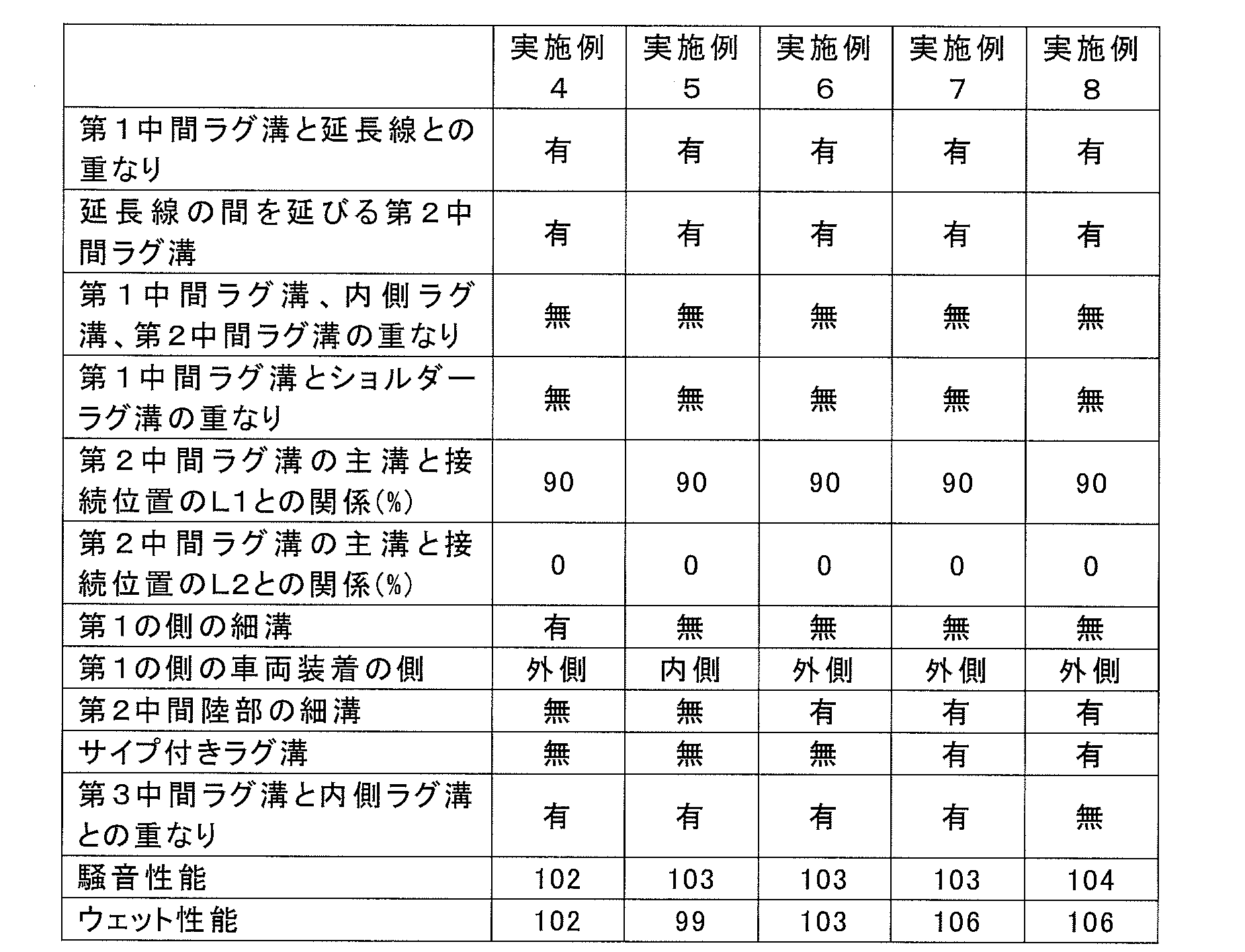
比較例1,2と実施例1~8との比較から、第1中間ラグ溝が延長線と重なり、第2中間ラグ溝が、隣り合う延長線の間を延長線に沿って延びていることで、ウェット性能の低下を抑えつつ、騒音性能を従来に比べて向上することがわかる。
実施例1と実施例2の比較から、タイヤ周方向に沿った第1中間ラグ溝、内側ラグ溝、第2中間ラグ溝の範囲の重なりがないことによって、騒音性能が向上することがわかる。
実施例1と実施例3の比較から、第2中間ラグ溝の第1周方向主溝との接続位置とL1あるいはL2との関係が、上記実施形態で説明した関係を満たすことで、騒音性能が向上することがわかる。
実施例1と実施例4の比較から、内側陸部あるいは第1中間陸部の領域にタイヤ周方向細溝を備えないことで騒音性能が向上することがわかる。
実施例1と実施例2の比較から、タイヤ周方向に沿った第1中間ラグ溝、内側ラグ溝、第2中間ラグ溝の範囲の重なりがないことによって、騒音性能が向上することがわかる。
実施例1と実施例3の比較から、第2中間ラグ溝の第1周方向主溝との接続位置とL1あるいはL2との関係が、上記実施形態で説明した関係を満たすことで、騒音性能が向上することがわかる。
実施例1と実施例4の比較から、内側陸部あるいは第1中間陸部の領域にタイヤ周方向細溝を備えないことで騒音性能が向上することがわかる。
実施例1と実施例5の比較から、第1の側が車両装着外側に配置されていることで、騒音性能が向上することがわかる。
実施例1と実施例6の比較から、第2中間陸部に細溝が設けられていることで、ウェット性能が向上することがわかる。
実施例6と実施例7の比較から、サイプ付きラグ溝が設けられていることで、ウェット性能が向上することがわかる。
実施例7と実施例8の比較から、タイヤ周方向に沿った第3中間ラグ溝、内側ラグ溝の重なりがないことで、騒音性能が向上することがわかる。
実施例1と実施例6の比較から、第2中間陸部に細溝が設けられていることで、ウェット性能が向上することがわかる。
実施例6と実施例7の比較から、サイプ付きラグ溝が設けられていることで、ウェット性能が向上することがわかる。
実施例7と実施例8の比較から、タイヤ周方向に沿った第3中間ラグ溝、内側ラグ溝の重なりがないことで、騒音性能が向上することがわかる。
以上、本発明の空気入りタイヤについて詳細に説明したが、本発明の空気入りタイヤは上記実施形態あるいは実施例に限定されず、本発明の主旨を逸脱しない範囲において、種々の改良や変更をしてもよいのはもちろんである。
10 タイヤ
10T トレッド部
10S サイド部
10B ビード部
12 カーカスプライ
14 ベルト
16 ビードコア
18 トレッドゴム部材
20 サイドゴム部材
22 ビードフィラーゴム部材
24 リムクッションゴム部材
26 インナーライナーゴム部材
21,23,25,27 主溝
31,33 細溝
40,40A,40B,40C,40D 第1のサイプ付きラグ溝
41 第2のサイプ付きラグ溝
51,53,55,57 ラグ溝
58,59 ショルダーラグ溝
51a 閉塞端
61 サイプ
61b 底上げ部
71A,71B,73,75,77A,77B,79 領域
10T トレッド部
10S サイド部
10B ビード部
12 カーカスプライ
14 ベルト
16 ビードコア
18 トレッドゴム部材
20 サイドゴム部材
22 ビードフィラーゴム部材
24 リムクッションゴム部材
26 インナーライナーゴム部材
21,23,25,27 主溝
31,33 細溝
40,40A,40B,40C,40D 第1のサイプ付きラグ溝
41 第2のサイプ付きラグ溝
51,53,55,57 ラグ溝
58,59 ショルダーラグ溝
51a 閉塞端
61 サイプ
61b 底上げ部
71A,71B,73,75,77A,77B,79 領域
Claims (15)
- トレッドパターンを備える空気入りタイヤであって、
前記トレッドパターンは、互いに間隔をあけてタイヤ周方向に延びる少なくとも3本の周方向主溝と、
前記周方向主溝のうちタイヤ幅方向の最も外側に位置する第1周方向主溝のタイヤ幅方向外側に位置し、タイヤ幅方向の接地端が位置するショルダー陸部の領域に設けられ、タイヤ幅方向外側から前記第1周方向主溝に向かって延びて前記第1周方向主溝に到達することなく閉塞し、タイヤ周方向に間隔をあけて配置された複数のショルダーラグ溝と、
前記第1周方向主溝と、前記少なくとも3本の周方向主溝のうち、前記第1周方向主溝のタイヤ幅方向内側に前記第1周方向主溝に最も接近して位置する第2周方向主溝との間の中間陸部の領域に設けられ、前記第2周方向主溝から前記第1周方向主溝に向かって延びて前記第1周方向主溝に到達することなく閉塞し、タイヤ周方向に間隔をあけて配置された複数の第1中間ラグ溝と、
前記第2周方向主溝と、前記少なくとも3本の周方向主溝のうち、前記第2周方向主溝に対して前記第1周方向主溝と反対側に位置する第3周方向主溝との間の内側陸部の領域に設けられ、前記第3周方向主溝から前記第2周方向主溝に向かって延びて前記第2周方向主溝に到達することなく閉塞し、タイヤ周方向に間隔をあけて配置された複数の内側ラグ溝と、
前記中間陸部の領域に設けられ、前記第1周方向主溝から前記第2周方向主溝に向かって延びて前記第2周方向主溝に到達することなく閉塞し、タイヤ周方向に間隔をあけて配置された複数の第2中間ラグ溝と、を備え、
前記ショルダーラグ溝の閉塞端を含み、前記第1周方向主溝側に位置する前記ショルダーラグ溝の主溝側部分は、タイヤ幅方向に対して傾斜して延び、
前記第1中間ラグ溝及び前記内側ラグ溝それぞれのタイヤ幅方向の一方から他方に向かう方向は、タイヤ幅方向に対して、前記主溝側部分のタイヤ幅方向の前記一方から前記他方に向かう方向が傾斜する側と同じ側に傾斜し、
前記ショルダーラグ溝それぞれの閉塞端から前記ショルダーラグ溝それぞれを、前記主溝側部分の傾斜方向に沿って滑らかに延長して前記内側ラグ溝の閉塞端のそれぞれに向かって延びる複数の延長線に対して、前記第1中間ラグ溝は重なっており、
前記第2中間ラグ溝は、前記延長線のうちタイヤ周方向に隣り合う2本の延長線の間を、前記延長線に沿った方向に延びている、ことを特徴とする空気入りタイヤ。 - 前記ショルダーラグ溝及び前記内側ラグ溝のすべてが、前記延長線のうちのいずれかの延長線の延在方向の端をなし、
前記第1中間ラグ溝のすべてが前記延長線のいずれかと重なっており、
前記第2中間ラグ溝のすべてが、タイヤ周方向に隣り合う前記2本の延長線の間のうちいずれかの間を延びている、請求項1に記載の空気入りタイヤ。 - タイヤ周方向に沿った前記第1中間ラグ溝の範囲、タイヤ周方向に沿った前記内側ラグ溝の範囲、及びタイヤ周方向に沿った前記第2中間ラグ溝の範囲は、互いに重なっていない、請求項1又は2に記載の空気入りタイヤ。
- タイヤ周方向に沿った前記第1中間ラグ溝の範囲は、タイヤ周方向に沿った前記ショルダーラグ溝の範囲と重なっていない、請求項1から3のいずれか1項に記載の空気入りタイヤ。
- 前記第1中間ラグ溝のうちタイヤ周方向に隣り合う2つの第1中間ラグ溝それぞれが前記第2周方向主溝に接続する2つの接続位置の間のタイヤ周方向に沿った長さをL1としたとき、前記第2中間ラグ溝の前記第1周方向主溝の側の端のタイヤ周方向の位置は、前記接続位置のうちの一方の接続位置から前記長さL1の50~95%の範囲内にある、請求項1から4のいずれか1項に記載の空気入りタイヤ。
- 前記ショルダーラグ溝のうちタイヤ周方向に隣り合う2つのショルダーラグ溝の閉塞端の間のタイヤ周方向に沿った長さをL2としたとき、前記第2中間ラグ溝の前記第1周方向主溝の側の端のタイヤ周方向の位置は、当該閉塞端の間のタイヤ周方向における中間点を中心とする前記長さL2の30%の範囲内にある、請求項1から5のいずれか1項に記載の空気入りタイヤ。
- 前記中間陸部の領域には、前記延長線と重なり前記第1周方向主溝に接続するラグ溝は設けられていない、請求項1から6のいずれか1項に記載の空気入りタイヤ。
- 前記内側陸部の領域には、前記延長線と重なり前記第2周方向主溝に接続するラグ溝は設けられていない、請求項1から7のいずれか1項に記載の空気入りタイヤ。
- 前記中間陸部の領域及び前記内側陸部の領域には、前記周方向主溝より溝幅の狭い、タイヤ周方向に延びる周方向細溝は設けられていない、請求項1から8のいずれか1項に記載の空気入りタイヤ。
- タイヤ周方向に隣り合う前記2本の延長線のタイヤ周方向の範囲は重なっていない、請求項1から9のいずれか1項に記載の空気入りタイヤ。
- タイヤ赤道線に対して、前記第1周方向主溝が位置するタイヤ幅方向の第1の側は、前記空気入りタイヤを車両に装着する時、車両装着外側となるように装着される、請求項1から10のいずれか1項に記載の空気入りタイヤ。
- 前記トレッドパターンは、さらに、タイヤ赤道線に対して、前記第1周方向主溝が位置するタイヤ幅方向の第1の側と反対側の第2の側に設けられ、前記第3周方向主溝のタイヤ幅方向外側に位置し、タイヤ周方向に延びる第4周方向主溝を備え、
前記中間陸部を第1中間陸部というとき、前記第3周方向主溝と前記第4周方向主溝の間に第2中間陸部が位置し、前記第2中間陸部の領域には、前記周方向主溝より溝幅の狭い、タイヤ周方向に延びる周方向細溝が設けられている、請求項1から11のいずれか1項に記載の空気入りタイヤ。 - 前記トレッドパターンは、さらに、
前記第2中間陸部の領域に設けられ、前記第4周方向主溝から前記周方向細溝に向かって延びて前記周方向細溝に到達することなく閉塞し、タイヤ周方向に間隔をあけて配置された複数の第3中間ラグ溝と、
前記第2中間陸部の領域に設けられ、前記第3中間ラグ溝それぞれの閉塞端と前記第2中間陸部の領域の前記周方向細溝とを接続し、タイヤ周方向に間隔をあけて配置された複数のサイプと、を備える、請求項12に記載の空気入りタイヤ。 - 互いに接続された前記第3中間ラグ溝及び前記サイプは、サイプ付きラグ溝として、
前記第3中間ラグ溝の延在方向と前記サイプの延在方向とが異なるよう屈曲して延びる第1のサイプ付きラグ溝と、
前記第3中間ラグ溝の延在方向と前記サイプの延在方向とが一致するよう直線状に延びる第2のサイプ付きラグ溝と、を含む、請求項13に記載の空気入りタイヤ。 - タイヤ周方向に沿った前記第3中間ラグ溝の範囲は、タイヤ周方向に沿った前記内側ラグ溝の範囲と重なっていない、請求項13又は14に記載の空気入りタイヤ。
Priority Applications (5)
| Application Number | Priority Date | Filing Date | Title |
|---|---|---|---|
| JP2019537197A JP7230809B2 (ja) | 2018-07-13 | 2019-06-25 | 空気入りタイヤ |
| RU2021103104A RU2752536C1 (ru) | 2018-07-13 | 2019-06-25 | Пневматическая шина |
| DE112019003564.9T DE112019003564T5 (de) | 2018-07-13 | 2019-06-25 | Luftreifen |
| US17/260,209 US12202298B2 (en) | 2018-07-13 | 2019-06-25 | Pneumatic tire |
| CN201980045502.7A CN112368159B (zh) | 2018-07-13 | 2019-06-25 | 充气轮胎 |
Applications Claiming Priority (2)
| Application Number | Priority Date | Filing Date | Title |
|---|---|---|---|
| JP2018-133672 | 2018-07-13 | ||
| JP2018133672 | 2018-07-13 |
Publications (1)
| Publication Number | Publication Date |
|---|---|
| WO2020012947A1 true WO2020012947A1 (ja) | 2020-01-16 |
Family
ID=69142918
Family Applications (1)
| Application Number | Title | Priority Date | Filing Date |
|---|---|---|---|
| PCT/JP2019/025076 Ceased WO2020012947A1 (ja) | 2018-07-13 | 2019-06-25 | 空気入りタイヤ |
Country Status (6)
| Country | Link |
|---|---|
| US (1) | US12202298B2 (ja) |
| JP (1) | JP7230809B2 (ja) |
| CN (1) | CN112368159B (ja) |
| DE (1) | DE112019003564T5 (ja) |
| RU (1) | RU2752536C1 (ja) |
| WO (1) | WO2020012947A1 (ja) |
Citations (6)
| Publication number | Priority date | Publication date | Assignee | Title |
|---|---|---|---|---|
| JP2009248961A (ja) * | 2008-04-11 | 2009-10-29 | Yokohama Rubber Co Ltd:The | 空気入りタイヤ |
| WO2015037464A1 (ja) * | 2013-09-11 | 2015-03-19 | 住友ゴム工業株式会社 | 空気入りタイヤ |
| WO2015079858A1 (ja) * | 2013-11-27 | 2015-06-04 | 横浜ゴム株式会社 | 空気入りタイヤ |
| JP2016101804A (ja) * | 2014-11-27 | 2016-06-02 | 住友ゴム工業株式会社 | 空気入りタイヤ |
| JP2016113003A (ja) * | 2014-12-15 | 2016-06-23 | 横浜ゴム株式会社 | 空気入りタイヤ |
| JP2017013672A (ja) * | 2015-07-02 | 2017-01-19 | 住友ゴム工業株式会社 | 空気入りタイヤ |
Family Cites Families (12)
| Publication number | Priority date | Publication date | Assignee | Title |
|---|---|---|---|---|
| JP2010126076A (ja) * | 2008-11-28 | 2010-06-10 | Bridgestone Corp | タイヤ |
| JP5146564B2 (ja) * | 2011-05-10 | 2013-02-20 | 横浜ゴム株式会社 | 空気入りタイヤ |
| JP5890796B2 (ja) * | 2013-04-11 | 2016-03-22 | 住友ゴム工業株式会社 | 空気入りタイヤ |
| JP6436080B2 (ja) | 2013-07-12 | 2018-12-12 | 横浜ゴム株式会社 | 空気入りタイヤ |
| JP2015134581A (ja) * | 2014-01-17 | 2015-07-27 | 横浜ゴム株式会社 | 空気入りタイヤ |
| US9789733B2 (en) * | 2014-02-14 | 2017-10-17 | Sumitomo Rubber Industries, Ltd. | Pneumatic tire |
| JP5796655B1 (ja) | 2014-03-28 | 2015-10-21 | 横浜ゴム株式会社 | 空気入りタイヤ |
| JP6063918B2 (ja) * | 2014-12-26 | 2017-01-18 | 住友ゴム工業株式会社 | 空気入りタイヤ |
| JP2017024661A (ja) | 2015-07-27 | 2017-02-02 | 横浜ゴム株式会社 | 空気入りタイヤ |
| JP6790496B2 (ja) | 2016-06-24 | 2020-11-25 | 住友ゴム工業株式会社 | 空気入りタイヤ |
| JP6848359B2 (ja) * | 2016-11-08 | 2021-03-24 | 住友ゴム工業株式会社 | タイヤ |
| JP6930241B2 (ja) | 2017-06-19 | 2021-09-01 | 横浜ゴム株式会社 | 空気入りタイヤ |
-
2019
- 2019-06-25 RU RU2021103104A patent/RU2752536C1/ru active
- 2019-06-25 WO PCT/JP2019/025076 patent/WO2020012947A1/ja not_active Ceased
- 2019-06-25 US US17/260,209 patent/US12202298B2/en active Active
- 2019-06-25 DE DE112019003564.9T patent/DE112019003564T5/de active Pending
- 2019-06-25 CN CN201980045502.7A patent/CN112368159B/zh active Active
- 2019-06-25 JP JP2019537197A patent/JP7230809B2/ja active Active
Patent Citations (6)
| Publication number | Priority date | Publication date | Assignee | Title |
|---|---|---|---|---|
| JP2009248961A (ja) * | 2008-04-11 | 2009-10-29 | Yokohama Rubber Co Ltd:The | 空気入りタイヤ |
| WO2015037464A1 (ja) * | 2013-09-11 | 2015-03-19 | 住友ゴム工業株式会社 | 空気入りタイヤ |
| WO2015079858A1 (ja) * | 2013-11-27 | 2015-06-04 | 横浜ゴム株式会社 | 空気入りタイヤ |
| JP2016101804A (ja) * | 2014-11-27 | 2016-06-02 | 住友ゴム工業株式会社 | 空気入りタイヤ |
| JP2016113003A (ja) * | 2014-12-15 | 2016-06-23 | 横浜ゴム株式会社 | 空気入りタイヤ |
| JP2017013672A (ja) * | 2015-07-02 | 2017-01-19 | 住友ゴム工業株式会社 | 空気入りタイヤ |
Also Published As
| Publication number | Publication date |
|---|---|
| DE112019003564T5 (de) | 2021-04-08 |
| RU2752536C1 (ru) | 2021-07-29 |
| CN112368159B (zh) | 2023-01-31 |
| US20210268841A1 (en) | 2021-09-02 |
| US12202298B2 (en) | 2025-01-21 |
| JPWO2020012947A1 (ja) | 2021-06-03 |
| CN112368159A (zh) | 2021-02-12 |
| JP7230809B2 (ja) | 2023-03-01 |
Similar Documents
| Publication | Publication Date | Title |
|---|---|---|
| WO2015005194A1 (ja) | 空気入りタイヤ | |
| JP6992533B2 (ja) | 空気入りタイヤ | |
| JP6610717B1 (ja) | 空気入りタイヤ | |
| JP7035550B2 (ja) | 空気入りタイヤ | |
| WO2019098307A1 (ja) | 空気入りタイヤ | |
| WO2018235400A1 (ja) | 空気入りタイヤ | |
| JP2019137340A (ja) | 空気入りタイヤ | |
| JP6119238B2 (ja) | 空気入りタイヤ | |
| JP6378634B2 (ja) | 自動二輪車用タイヤ | |
| JP7196588B2 (ja) | 空気入りタイヤ | |
| JP6421652B2 (ja) | 空気入りタイヤ | |
| CN114829163B (zh) | 轮胎 | |
| JP6848413B2 (ja) | 空気入りタイヤ | |
| JP2017052327A (ja) | 空気入りタイヤ | |
| JP7205475B2 (ja) | 空気入りタイヤ | |
| WO2020171226A1 (ja) | 空気入りタイヤ | |
| CN114746292B (zh) | 轮胎 | |
| JP7207304B2 (ja) | 空気入りタイヤ | |
| JP7633491B2 (ja) | タイヤ | |
| JP7230809B2 (ja) | 空気入りタイヤ | |
| JP7013765B2 (ja) | 空気入りタイヤ | |
| JP6624231B2 (ja) | 空気入りタイヤ | |
| WO2023153022A1 (ja) | タイヤ | |
| JP2021127006A (ja) | 空気入りタイヤ |
Legal Events
| Date | Code | Title | Description |
|---|---|---|---|
| ENP | Entry into the national phase |
Ref document number: 2019537197 Country of ref document: JP Kind code of ref document: A |
|
| 121 | Ep: the epo has been informed by wipo that ep was designated in this application |
Ref document number: 19834271 Country of ref document: EP Kind code of ref document: A1 |
|
| 122 | Ep: pct application non-entry in european phase |
Ref document number: 19834271 Country of ref document: EP Kind code of ref document: A1 |