WO2020008915A1 - 布類搬送装置 - Google Patents
布類搬送装置 Download PDFInfo
- Publication number
- WO2020008915A1 WO2020008915A1 PCT/JP2019/024738 JP2019024738W WO2020008915A1 WO 2020008915 A1 WO2020008915 A1 WO 2020008915A1 JP 2019024738 W JP2019024738 W JP 2019024738W WO 2020008915 A1 WO2020008915 A1 WO 2020008915A1
- Authority
- WO
- WIPO (PCT)
- Prior art keywords
- cloth
- rail
- traveling
- clamp
- corner
- Prior art date
Links
Images


Classifications
-
- B—PERFORMING OPERATIONS; TRANSPORTING
- B65—CONVEYING; PACKING; STORING; HANDLING THIN OR FILAMENTARY MATERIAL
- B65G—TRANSPORT OR STORAGE DEVICES, e.g. CONVEYORS FOR LOADING OR TIPPING, SHOP CONVEYOR SYSTEMS OR PNEUMATIC TUBE CONVEYORS
- B65G19/00—Conveyors comprising an impeller or a series of impellers carried by an endless traction element and arranged to move articles or materials over a supporting surface or underlying material, e.g. endless scraper conveyors
- B65G19/02—Conveyors comprising an impeller or a series of impellers carried by an endless traction element and arranged to move articles or materials over a supporting surface or underlying material, e.g. endless scraper conveyors for articles, e.g. for containers
- B65G19/025—Conveyors comprising an impeller or a series of impellers carried by an endless traction element and arranged to move articles or materials over a supporting surface or underlying material, e.g. endless scraper conveyors for articles, e.g. for containers for suspended articles
-
- D—TEXTILES; PAPER
- D06—TREATMENT OF TEXTILES OR THE LIKE; LAUNDERING; FLEXIBLE MATERIALS NOT OTHERWISE PROVIDED FOR
- D06F—LAUNDERING, DRYING, IRONING, PRESSING OR FOLDING TEXTILE ARTICLES
- D06F93/00—Counting, sorting, or marking arrangements specially adapted for laundry purposes
-
- B—PERFORMING OPERATIONS; TRANSPORTING
- B65—CONVEYING; PACKING; STORING; HANDLING THIN OR FILAMENTARY MATERIAL
- B65G—TRANSPORT OR STORAGE DEVICES, e.g. CONVEYORS FOR LOADING OR TIPPING, SHOP CONVEYOR SYSTEMS OR PNEUMATIC TUBE CONVEYORS
- B65G9/00—Apparatus for assisting manual handling having suspended load-carriers movable by hand or gravity
- B65G9/002—Load-carriers, rollers therefor
-
- B—PERFORMING OPERATIONS; TRANSPORTING
- B65—CONVEYING; PACKING; STORING; HANDLING THIN OR FILAMENTARY MATERIAL
- B65G—TRANSPORT OR STORAGE DEVICES, e.g. CONVEYORS FOR LOADING OR TIPPING, SHOP CONVEYOR SYSTEMS OR PNEUMATIC TUBE CONVEYORS
- B65G9/00—Apparatus for assisting manual handling having suspended load-carriers movable by hand or gravity
- B65G9/004—Loading or unloading arrangements
-
- B—PERFORMING OPERATIONS; TRANSPORTING
- B65—CONVEYING; PACKING; STORING; HANDLING THIN OR FILAMENTARY MATERIAL
- B65G—TRANSPORT OR STORAGE DEVICES, e.g. CONVEYORS FOR LOADING OR TIPPING, SHOP CONVEYOR SYSTEMS OR PNEUMATIC TUBE CONVEYORS
- B65G9/00—Apparatus for assisting manual handling having suspended load-carriers movable by hand or gravity
- B65G9/008—Rails or switches
-
- D—TEXTILES; PAPER
- D06—TREATMENT OF TEXTILES OR THE LIKE; LAUNDERING; FLEXIBLE MATERIALS NOT OTHERWISE PROVIDED FOR
- D06F—LAUNDERING, DRYING, IRONING, PRESSING OR FOLDING TEXTILE ARTICLES
- D06F67/00—Details of ironing machines provided for in groups D06F61/00, D06F63/00, or D06F65/00
- D06F67/04—Arrangements for feeding or spreading the linen
Definitions
- the present invention relates to a cloth transport device, and more particularly, to a cloth transport device for transporting cloth in linen equipment.
- This cloth transport device for transporting washed laundry in a linen facility from a supply position to a discharge position (see Patent Document 1 below).
- This cloth transport device includes a transport rail that circulates between a supply position and a discharge position.
- a plurality of traveling bodies that hold cloths can travel on the transport rail.
- the supply position is a position where the worker attaches (supplies) the cloth to the traveling body
- the discharge position is a position where the cloth held on the traveling body is discharged (handed over) to the processing device in the next process.
- the traveling body is provided with a horizontally provided beam and a pair of chucks provided at both left and right ends of the beam, and the cloths hang down by gripping the left and right corners with the pair of chucks. It moves along the transport rail while being held at.
- the cloth is attached to the traveling body by searching for a corner of a predetermined side of the cloth at the supply position, attaching the cloth to one of a pair of chucks, and then attaching the cloth to the traveling body.
- the procedure is performed by searching for the other corner and attaching it to the chuck on the opposite side.
- the work of searching for the other corner is performed by moving the cloth, and there is a problem that it takes time and effort to search for the other corner.
- a transport system in which a plurality of independent traveling clamps 10 travel on one transport rail 16 as shown in FIG.
- this transport system as shown in FIG. 10B, as soon as a corner of a predetermined side of the cloth C found earlier at the supply position is attached to the preceding traveling clamp 10, the traveling clamp 10 is raised. Since the other corner can appear by itself in front of the worker, the labor and time for searching for the other corner can be greatly reduced.
- a corner of cloth to be attached to the traveling clamp is designated, that is, a specific corner (for example, a right corner) is always attached to the preceding traveling clamp at the supply position, and
- the running travel clamp may have a restriction that a particular corner (eg, left corner) on the opposite side must always be attached.
- the corner found by the worker is the opposite corner, release that corner, search for the other specific corner, attach it to the preceding traveling clamp, and then first It is necessary to perform a complicated work of re-searching for the corner portion found in the above and mounting it again.
- the act of releasing the corner once found is very wasteful, and as a result, the transport efficiency is greatly reduced.
- the cloth transport device of the present invention includes a plurality of independent traveling clamps, a supply section in which corners of the cloth are attached to the traveling clamp, and a discharge section in which cloth is delivered from the traveling clamp. And a transport rail that circulates through the transport rail to individually travel the travel clamps, and branches the transport rail into a first supply rail and a second supply rail in the supply unit or before and after the supply unit. A branch point and a junction point where the branched first supply rail and the second supply rail merge again are provided.
- the first traveling clamp which is the traveling clamp located on the first supply rail, is for attaching a first corner which is a specific corner of cloth.
- the second traveling clamp which is the traveling clamp located on the second supply rail, is for attaching a second corner which is another specific corner of the cloth.
- the one in which the specific corner portion of the cloth is attached earlier in the first travel clamp and the second travel clamp is up to the standby position before the junction. It is configured to rise first.
- the first corner of the cloth is attached to the first traveling clamp, and the second corner of the cloth is attached to the second traveling clamp.
- a specific one of the first traveling clamp and the second traveling clamp always returns to the main line via the junction first.
- a branch point is provided at a position before the discharge section for branching the transport rail into a first discharge rail and a second discharge rail.
- the distribution of the traveling clamp to the first discharge rail and the second discharge rail at the branch point provided at a position in front of the discharge unit is performed by the discharge control. This is done in consideration of the direction of the front and back of the cloth discharged in the section.
- the transport rail in or before the supply unit, is branched into a first supply rail and a second supply rail via a branch point, and a predetermined side of the cloth is Of the right and left corners, the corner previously found by the operator can be attached to the corresponding travel clamp on the first supply rail or the travel clamp on the second supply rail.
- FIG. 1 It is a top view showing the schematic structure of the cloth conveyance device of one embodiment of the present invention. It is a side view of the supply part in the cloth conveyance apparatus of FIG. It is a figure which shows the branch point provided in the main line in the cloth conveyance apparatus of FIG. 1, (a) shows a mode that a travel clamp is distributed to an upper path
- 2A and 2B are diagrams illustrating a junction provided on a main line in the cloth transport device of FIG. 1, wherein FIG. 2A illustrates a state of merging from an upper path, and FIG. 2B illustrates a state of merging from a lower path; It is. 2A is a front view, FIG.
- FIG. 2B is an enlarged view of a portion A in FIG. 1A, and a traveling clamp is distributed to a first supply rail on the right side.
- (C) is an enlarged view of a portion A in (a) and shows a state in which the traveling clamp is distributed to the second supply rail on the left side.
- 2A is a rear view
- FIG. 2B is an enlarged view of a portion B in FIG. 1A, and a traveling clamp moves from a first supply rail on the left side to a main line in FIG. 1
- FIG. (C) is an enlarged view of a portion B in (a) and shows a state where the traveling clamp joins the main line from the second supply rail on the right side.
- (A)-(d) is a figure explaining operation
- (A)-(d) is a figure explaining operation
- the cloth transport device of the embodiment is for transporting the washed rectangular cloth in a hanging state to the next process in the linen equipment, especially when the corner of the cloth attached to the traveling clamp is specified. It is suitable for conveyance of
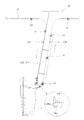
- FIG. 1 shows a schematic configuration of a cloth transport device according to an embodiment of the present invention.
- the cloth transport device includes a plurality of independent traveling clamps 10 and a cloth C applied to the traveling clamp 10 by an operator or the like.
- a transport rail 16 that circulates through the transport clamps 14 and individually travels the travel clamps 10, and a control unit (not shown) that controls the entire cloth transport apparatus including controls in the supply unit 12 and the discharge unit 14. .
- the processing apparatus T includes, for example, a cloth loading machine Ta, a roll ironer Tb connected downstream of the cloth loading machine Ta, and a cloth folding machine Tc connected downstream of the roll ironer Tb.
- the cloth loading machine Ta receives the cloth C from the traveling clamp 10 at the discharge section 14 and loads the cloth C into the roll ironer Tb.
- the roll ironer Tb irons the loaded cloth C.
- the folded cloth C is folded.
- the supply unit 12 receives the washed cloth C sent from the washing process, and the worker hangs the cloth C on the traveling clamp 10 on the transport rail 16.
- three supply units 12 are provided, but at least one supply unit 12 may be provided.
- the traveling clamp 10 is a moving body that travels on the transport rail 16, and has a traveling section 10A and a clamp section 10B as shown in an enlarged view in FIG.
- the traveling unit 10A has a main body 10A1, four traveling wheels 10A2 attached to left and right positions at both front and rear ends of the main body 10A1, and guide wheels (not shown) attached to front and rear positions of the main body 10A1.
- the traveling wheel 10A2 rolls on a traveling surface formed by an upward flat wall of the transport rail 16, and the guide wheel rolls along a guide surface configured by a vertical wall of the transport rail 16.
- the traveling clamp 10 travels on the transport rail 16 by the rolling of the traveling wheel 10A2 and the guide wheel.
- a clamp 10B is suspended from a main body 10A1 of the traveling unit 10A via a stay.
- two clamp portions 10B are provided adjacent to each other for one traveling clamp 10, but one clamp portion 10B may be provided.
- the two clamps 10B cooperate to grip one corner Cr, Cl of the cloth C.
- the clamp portion 10B is a known clamp including a swinging clamp claw 10B1 and a fixed facing plate 10B2.
- the structure of the clamp portion 10B is not limited as long as the cloth C can be held and released.
- the transport rail 16 is formed by connecting a plurality of rail members along a predetermined path.
- Each rail member is, for example, a pair of channel members 16a and 16b having a substantially U-shaped (C-shaped) cross section, and the opening sides thereof are opposed to each other. And are arranged in parallel so as to form a constant interval.
- Each rail material is not limited to the channel material but may be an L-shaped angle material as long as it has an upward flat wall forming the running surface described above and a vertical wall forming the guide surface. The material may be oriented with its groove side downward and the pair of lip portions may be used as a running surface.
- the transport rail 16 be installed at a position high enough so that the cloth C suspended and held by the traveling clamp 10 does not come into contact with the ground or the like and becomes soiled, except for a specific range of the supply unit 12 or the like.
- the transport rail 16 has a forced movement section in which the traveling clamp 10 is forcibly moved by a driving mechanism (not shown), and a free movement section in which the traveling clamp 10 has a downward inclination and descends and moves under its own weight.
- the drive mechanism is composed of a pair of pulleys, a toothed belt suspended between the pulleys, and a drive motor for rotating the pulleys.
- the traveling clamps 10 can be individually moved along the transport rails 16 by engaging with, for example, the upper surface of the 10.
- a chain may be used instead of the toothed belt.
- the transport rail 16 also has a branch point 16A where the main line branches into three in order to provide the traveling clamp 10 to each supply unit 12, and a junction point 16B where the branch paths are merged again.
- a branch point 16C for distributing the traveling clamp 10 to the left and right first discharge rails 161 and the second discharge rail 162 alternately or in a predetermined order is provided in front of the discharge unit 14.
- the transport rail 16 can be provided with four or more discharge rails (not shown) according to the number of charging points in the cloth loading machine Ta (not shown).
- a point 16D is provided. Switching devices 18 as shown in FIGS. 3 and 4 are provided at the junctions 16A and 16C and the junctions 16B and 16D, respectively.
- the switching device 18 has a tapered shape, a switching guide portion 18a pivotally supported on the base end side such that the distal end side swings, and a driving means for switching the rail to travel by swinging the switching guide portion 18a.
- the drive means is a cylinder in the illustrated example, but a motor can be used. Note that the switching device 18 may be omitted at the junctions 16B and 16D. In this case, the traveling clamp 10 that has reached the merging points 16B and 16D first merges first.
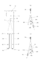
- the transport rail 16 extends downward from a high main line position to a height position of the upper body of the worker at each supply unit 12, and then extends upward toward the main line again. It has a U-shape. Thereby, the worker can attach the cloth C to the traveling clamp 10 in the supply section 12.
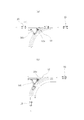
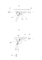
- the transport rail 16 also includes a first supply rail 163 on the right side and a second supply rail on the left side as viewed from the operator at the branch point (branch position) 12A on the front side even in each supply unit 12. After branching into the rail and 164, as shown in FIG. 6, they merge again at a merging point (merging position) 12B on the back side.
- a switching device 20 is provided at each of a branch point 12A and a junction 12B in the supply unit 12.
- the switching device 20 has a tapered shape, a switching guide portion 20a pivotally supported on the base end side such that the distal end side swings, and a driving means for switching the rail to travel by swinging the switching guide portion 20a.
- the driving means is a cylinder in the illustrated example, but a motor can be used.
- the traveling clamp 10 is alternately distributed to the first supply rail 163 on the right and the second supply rail 164 on the left.
- FIG. 5B shows that the switching device 20 distributes the traveling clamp 10 to the first supply rail 163 on the right side
- FIG. 5C shows that the switching device 20 distributes the traveling clamp 10 to the second supply rail 164 on the left side. Is shown.
- the traveling clamp 10 on the first supply rail 163 and the traveling clamp 10 on the second supply rail 164 are returned to the main line in a predetermined order.
- FIG. 6B shows a state in which the switching device 20 returns the traveling clamp 10 to the main line from the first supply rail 163 on the left side
- FIG. 6C shows a state where the traveling clamp 10 is returned to the main line from the second supply rail 164 on the right side. Shows how to return.
- the switching device 20 may be omitted.
- the traveling clamp 10 that has reached the junction 12B first is merged first.
- a drive mechanism as described above may be provided that allows the traveling clamp 10 always located on a specific side of the first and second supply rails 163 and 164 to reach and pass the junction 12B.
- the traveling clamp 10 on the first supply rail 163 and the traveling clamp 10 on the second supply rail 164 can move independently of each other.
- a drive mechanism (not shown) can be provided on each of the first supply rail 163 and the second supply rail 164.
- the drive mechanism is composed of a pair of pulleys, a toothed belt suspended between the pulleys, and a drive motor for rotating the pulleys.
- the traveling clamps 10 can be individually moved along the transport rails 16 by engaging with, for example, the upper surface of the 10.
- the power of one drive motor is alternately transmitted to the toothed belt for the first supply rail 163 and the toothed belt for the second supply rail 164 via a clutch, so that The traveling clamp 10 and the traveling clamp 10 on the second supply rail 164 may be moved independently of each other.
- a chain may be used instead of the toothed belt.
- the cloth C coming out of the supply unit 12 is preceded with the right corner Cr as the first corner.
- a description will be given of a usage example of causing the left corner Cl to follow as the second corner.
- the left corner Cl may precede the first corner and the right corner Cr may precede the second corner.
- the worker searches for a right corner Cr or a left corner Cl on a predetermined side such as a short side of the cloth C, and finds the right corner Cr first.
- the right corner Cr is attached to the traveling clamp 10 (hereinafter, also referred to as the first traveling clamp 10) on the first supply rail 163.
- the first traveling clamp 10 to which the right corner Cr is attached rises in advance to the standby position 12C just before the merging position, and with this rise, the left in front of the worker.
- the operator attaches the left corner Cl that has appeared to the traveling clamp 10 on the second supply rail 164 (hereinafter, also referred to as the second traveling clamp 10).
- the distance to be raised in advance is preferably equal to or less than the length of the predetermined side of the cloth C, and more preferably equal to the length of the predetermined side of the cloth C.
- the worker finds the left corner Cl of the cloth C in the supply unit 12 first, the worker attaches the left corner Cl to the second traveling clamp 10 as shown in FIG. .
- the second traveling clamp 10 to which the left corner Cl is attached rises up to the standby position 12C just before the merging position, and in front of the worker with this rise. Since the right corner Cr appears by itself, the worker attaches the right corner Cr that has appeared to the first traveling clamp 10.
- the distance to be raised in advance is preferably equal to or less than the length of the predetermined side of the cloth C, and more preferably equal to the length of the predetermined side of the cloth C.
- the first traveling clamp 10 moves forward and overtakes the second traveling clamp 10 stopped at the standby position 12C. It returns to the main line first through the junction 12B. Subsequently, the second traveling clamp 10 moves forward and returns to the main line after passing through the junction 12B. Therefore, also in this case, as shown in FIG. 8D, the cloths C coming out of the supply unit 12 are discharged from the discharge unit 12 in such an order that the right corner Cr is the leading side and the left corner Cl is the trailing side. It is conveyed toward 14.
- the traveling clamp 10 holding the cloth C travels on the transport rail 16 toward the discharge unit 14 as shown in FIG.
- the traveling clamp 10 on the leading side and the traveling clamp 10 on the trailing side in front of the discharge unit 14 are alternately distributed to the first and second discharge rails 161 and 162 on the left and right via a branch point 16C.
- the traveling clamp 10 that has reached 14 transfers the held cloth C to the cloth input machine Ta.
- the empty traveling clamp 10 after the cloth C is delivered to the cloth input machine Ta travels on the transport rail 16 and returns to the supply unit 12 again.
- the traveling clamp 10 is distributed to three supply units 12 at a predetermined ratio via a branch point 16A.
- the transport rail 16 is branched into the first supply rail 163 and the second supply rail 164 at the branch point 12A, and the worker is moved between the right corner Cr and the left corner Cl.
- the previously found corner Cr or Cl can be attached to the corresponding traveling clamp 10 on the first supply rail 163 or the traveling clamp 10 on the second supply rail 164. This eliminates the need for the complicated operation of once releasing the corner Cr or Cl found first by the operator, re-searching for the released corner Cr or Cl later, and attaching the same again. Class C can be efficiently mounted without waste.
- first travel clamp 10 and the second travel clamp 10 to which the corner Cr or Cl is attached earlier rises up to the standby position 12C according to a preferred example, the worker is accompanied by this rise.
- the operator can easily find the specific corner Cl or Cr on the opposite side because the specific corner Cl or Cr on the opposite side appears by himself.
- first corner portion (for example, Cr) of the cloth C is attached to the first traveling clamp 10 and the second corner portion (for example, Cl) of the cloth C is attached to the second traveling clamp 10
- a specific one of the first traveling clamp 10 and the second traveling clamp 10 is always configured to return to the main line via the junction 12B first.
- the cloth C that has come out of the supply unit 12 can always be conveyed in such an order that a specific corner (for example, Cr) is on the leading side and the opposite corner (for example, Cl) is on the trailing side.
- a branch point 16C for branching the transport rail 16 into the first discharge rail 161 and the second discharge rail 162 is provided at a position before the discharge unit 14, and according to the preferable example, the transport rail 16 and the cloth loading are provided.
- the cloth C can be transported to the front of the cloth input machine Ta while avoiding interference with the cloth Ta.
- the distribution of the traveling clamp 10 to the first discharge rail 161 and the second discharge rail 162 at the branch point 16C provided in front of the discharge unit 14 is performed by the cloth C discharged by the discharge unit 14. It can be performed in consideration of the orientation of the front and back.
- the first discharge rail 161 and the first discharge rail 161 are provided at a branch point 16C before the discharge unit 14.
- the direction of the front and back of the cloth C in the discharge unit 14 may be adjusted through rectification by the distribution control of the traveling clamp 10 to the second discharge rail 162.
- an individual management unit such as an IC chip or a two-dimensional code is mounted on the traveling clamp 10, and information on whether the corner held by the traveling clamp 10 is right or left using the individual management unit.
- the information is read by the reading means before the merging point, so that the cloth clamp 10 is transferred to the cloth loading machine Ta at the branch point 16C just before the discharge unit 14 so that the cloth C is turned over to the cloth loading machine Ta in a specific front and back direction. Can be controlled.
- the maintenance time of the traveling clamp 10 can be grasped by using the individual management means, or the difference in the loading mode of the cloth loading machine Ta (for example, the one-lane loading mode using only the first and second discharge rails 161 and 162).
- the cloth C can be retracted in accordance with the first and second discharge rails 161 and 162 and a two-lane input mode (not shown) using third and fourth discharge rails.
- the branch point 12A is disposed immediately before (upstream side) the supply unit 12 and the junction 12B is located immediately after (supply side) the supply unit 12. It differs from the cloth transport device 10 of the above-described embodiment in that it is arranged.
- the first and second supply rails 163 and 164 are juxtaposed over the entire area of the supply section 12 having a substantially U-shape in side view. This eliminates the necessity of installing the branch point 12A and the junction 12B in the supply unit 12, which often has a limited space, so that the size thereof can be avoided.
- a switching device 20 as shown in FIG. 5 is provided at a branch point 12 ⁇ / b> A arranged before the supply unit 12.
- the switching device 20 as shown in FIG. 6 is provided at the junction 12B disposed after the supply unit 12, but may be omitted in some cases.
- the traveling clamp 10 that has reached the junction 12B first is merged first.
- the above-described drive mechanism for always causing the traveling clamp 10 on the specific side of the first and second supply rails 163 and 164 to reach and pass the junction 12B may be provided. Good. Also in the present embodiment, it is preferable to provide the standby position 12C in the supply unit 12.
- traveling clamp 12 supply unit 12A junction 12B junction 12C standby position 14 ejection unit 16 transport rail 161 first ejection rail 162 second ejection rail 163 first supply rail 164 second supply rail 16A, 16C junction 16B, 16D junction Point 18 Switching device 20 Switching device T Processing device
Abstract
走行クランプに取り付ける布類の角部に指定がある場合においても、走行クランプへの布類の取り付けを無駄なく効率的に行うことが可能な布類搬送装置を提供する。布類搬送装置は、複数個の独立した走行クランプ10と、走行クランプ10への布類Cの角部の取り付けが行われる供給部12および走行クランプ10からの布類Cの引き渡しが行われる排出部14を経由して循環し、走行クランプ10を個々に走行させる搬送レール16とを備える。供給部12内には、搬送レール16を第1供給レール163と第2供給レール164とに分岐させる分岐点12Aと、分岐した第1供給レール163と第2供給レール164とを再び合流させる合流点12Bとが設けられている。
Description
本発明は、布類搬送装置に関し、より詳しくは、リネン設備において布類を搬送するための布類搬送装置に関する。
本発明者らは先に、リネン設備において洗濯済みの布類を供給位置から排出位置に搬送するための布類搬送装置を提案している(下記特許文献1参照)。この布類搬送装置は、供給位置と排出位置とを循環する搬送レールを備えている。搬送レールは、布類を保持する複数の走行体が走行可能となっている。
供給位置は作業員が布類を走行体に取り付ける(供給する)位置であり、排出位置は走行体に保持された布類を、次工程の処理装置に排出する(引き渡す)位置である。走行体は、水平に設けられた梁と、梁の左右両端部に設けられた一対のチャックとを備えており、布類はその左右の角部が一対のチャックで把持されることによって垂下姿勢に保持されたまま、搬送レールに沿って移動する。
この布類搬送装置において布類の走行体への取付けは、作業者が供給位置にて布類の所定の辺の角部を探して一対のチャックのうちの一方に取り付けた後、当該辺の他方の角部を探して反対側のチャックに取り付けるという手順で行われる。この際、当該他方の角部を探す作業は布類をたぐり寄せることで行われ、他方の角部を探すのに手間と時間がかかるという問題がある。
走行体に左右2つのチャックを取り付けるのに代えて、図10(a)に示すように各々独立した複数の走行クランプ10が一本の搬送レール16上を走行する搬送システムも考えられる。この搬送システムでは、図10(b)に示すように、供給位置において先に見つけた布類Cの所定の辺の角部を先行する走行クランプ10に取り付けるとすぐにその走行クランプ10を上昇させることができ、それに伴い作業者の目の前に他方の角部が自ら出現するので、他方の角部を探す手間と時間が大幅に減少する。
しかし、このような搬送システムにおいても、走行クランプに取り付ける布類の角部に指定がある場合、つまり、供給位置において先行する走行クランプに、常に特定の角部(例えば右角部)を取り付け、後行する走行クランプには、反対側の特定の角部(例えば左角部)を常に取り付けなければならないという制約がある場合がある。この場合、作業者が折角見つけた角部が反対側の角部であった場合には、その角部を放し、もう一方の特定の角部を探して先行する走行クランプに取り付けた後、最初に見つけた角部をもう一度探しなおし、取り付けるという煩雑な作業が必要となる。折角見つけた角部を一度放すという行為は大変な無駄であり、結果、搬送効率の大幅な悪化につながる。
本発明の目的は、走行クランプに取り付ける布類の角部の指定がある場合においても、走行クランプへの布類の取り付けを無駄なく効率的に行うことが可能な布類搬送装置を提供することにある。
本発明の布類搬送装置は、複数個の独立した走行クランプと、前記走行クランプへの布類の角部の取り付けが行われる供給部および前記走行クランプからの布類の引き渡しが行われる排出部を経由して循環し、前記走行クランプを個々に走行させる搬送レールと、を備え、前記供給部内または前記供給部の前後に、前記搬送レールを第1供給レールと第2供給レールとに分岐させる分岐点と、分岐した前記第1供給レールと前記第2供給レールとを再び合流させる合流点とが設けられているものである。
本発明の布類搬送装置の好適な態様では、前記第1供給レールに位置する前記走行クランプである第1走行クランプは、布類の特定の角部である第1角部を取り付けるためのものであり、前記第2供給レールに位置する前記走行クランプである第2走行クランプは、布類の他の特定の角部である第2角部を取り付けるためのものである。
本発明の布類搬送装置の好適な態様では、前記第1走行クランプおよび第2走行クランプのうち先に布類の前記特定の角部が取り付けられた方が、前記合流点手前の待機位置まで先行して上昇するよう構成されている。
本発明の布類搬送装置の好適な態様では、前記第1走行クランプに布類の前記第1角部が取り付けられかつ前記第2走行クランプに該布類の前記第2角部が取り付けられた状態において、常に、前記第1走行クランプおよび前記第2走行クランプのうち特定の一方が先に前記合流点を介して本線に復帰するよう構成されている。
本発明の布類搬送装置の好適な態様では、前記排出部の手前位置に前記搬送レールを第1排出レールと第2排出レールとに分岐させる分岐点が設けられている。
本発明の布類搬送装置の好適な態様では、前記排出部の手前位置に設けられた前記分岐点での前記第1排出レールおよび前記第2排出レールへの前記走行クランプの分配は、前記排出部にて排出される布類の表裏の向きを考慮して行われる。
本発明の布類搬送装置にあっては、供給部内またはその前において、搬送レールが分岐点を介して第1供給レールと第2供給レールとに分岐されており、布類の所定の辺の右角部と左角部のうち作業者が先に見つけた角部をそれに対応した第1供給レール上の走行クランプまたは第2供給レール上の走行クランプに取り付けることができる。これにより、作業者が最初に見つけた角部を一旦放して、その放した角部を後でもう一度探しなおし、取り付けるという煩雑な作業が不要となり、走行クランプへの布類の取り付けを無駄なく効率的に行うことができる。
以下、本発明の実施の形態を図面に基づき詳細に説明する。実施形態の布類搬送装置は、リネン設備において、洗濯済みの矩形状の布類を次工程まで垂下状態で搬送するものであり、特に、走行クランプに取り付ける布類の角部に指定がある場合の搬送に適したものである。
図1に、本発明の一実施形態の布類搬送装置の概略構成を示し、この布類搬送装置は、複数個の独立した走行クランプ10と、作業者等によって走行クランプ10への布類Cの角部Cr,Clの取り付けが行われる供給部12と、走行クランプ10で保持した布類Cを次工程の処理装置Tに引き渡す(排出する)排出部14と、少なくとも供給部12および排出部14を経由して循環し、走行クランプ10を個々に走行させる搬送レール16と、供給部12および排出部14における制御を含む布類搬送装置全体の制御を行う図示しない制御部とを備えている。処理装置Tは例えば、布類投入機Taと、布類投入機Taの下流側に接続されたロールアイロナTbと、ロールアイロナTbの下流側に接続された布類折畳機Tcとを備える。布類投入機Taは、排出部14において走行クランプ10から布類Cを受け取るとともにロールアイロナTbに投入し、ロールアイロナTbは投入された布類Cのアイロンがけを行い、布類折畳機Tcはアイロンがけされた布類Cの折畳みを行う。
供給部12では、洗濯工程から送られてきた洗濯済みの布類Cを受け取り、作業員がその布類Cを搬送レール16上の走行クランプ10に吊り下げる作業を行う。図示例では、3つの供給部12が設けられているが、供給部12は少なくとも1つあればよい。
走行クランプ10は、搬送レール16上を走行する移動体であり、図1中の拡大図に示すように、走行部10Aとクランプ部10Bとを有している。走行部10Aは、本体10A1と、本体10A1の前後両端で左右位置に取り付けられた4個の走行輪10A2と、本体10A1の前後位置に取り付けられたガイド輪(図示せず)とを有する。走行輪10A2は、搬送レール16の上向き平面壁から構成される走行面上を転動し、ガイド輪は搬送レール16の垂直壁で構成されるガイド面に沿って転動する。これらの走行輪10A2およびガイド輪の転動により走行クランプ10が搬送レール16上を走行する。
走行部10Aの本体10A1からはステーを介してクランプ部10Bが吊持されている。図示例では、1つの走行クランプ10につき2つのクランプ部10Bが互いに近接して設けられているが、クランプ部10Bは1つでもよい。2つのクランプ部10Bは協働して布類Cの1つの角部Cr,Clを把持するものである。クランプ部10Bは、図2中の拡大図に示すように、揺動するクランプ爪10B1と固定の対面板10B2とからなる公知のクランプである。布類Cを保持、解放可能であれば、クランプ部10Bの構造に限定はない。
搬送レール16は、複数のレール材を所定の経路に沿って連結してなり、各レール材は例えば、断面略コ字(C字)形の一対のチャンネル材16a,16bを、その開口側が対向しかつ一定の間隔が形成されるように平行に配設してなる。各レール材は、上述した走行面を構成する上向き平面壁と、ガイド面を構成する垂直壁とを有するものであれば、チャンネル材に限らずL字形のアングル材でもよく、あるいは、リップ溝形材を、その溝側を下方に配向しその一対のリップ部を走行面としてもよい。搬送レール16は、供給部12等の特定の範囲を除いて、走行クランプ10によって垂下保持された布類Cが地面等に接触して汚損しないよう十分に高い位置に設置するのが好ましい。搬送レール16は、図示しない駆動機構によって走行クランプ10を強制的に移動させる強制移動区間と、下向きの傾斜を有し走行クランプ10が自重により降下、移動する自由移動区間とを有する。駆動機構の一例は、一対のプーリと、該プーリ間に掛架された歯付きベルトと、プーリを回転させる駆動モータとからなるものであり、駆動モータを介して周回する歯付きベルトが走行クランプ10の例えば上面部に噛み合うことで、走行クランプ10は搬送レール16に沿って個々に移動可能である。歯付きベルトに代えてチェーンを用いてもよい。
搬送レール16はまた、各供給部12に走行クランプ10を提供するために本線を3つに分岐する分岐点16Aと、分岐した経路を再び合流する合流点16Bを有している。また、排出部14の手前にも走行クランプ10を左右の第1排出レール161と第2排出レール162とに交互にもしくは所定の順序で振り分ける分岐点16Cが設けられている。搬送レール16には、布類投入機Taにおける投入箇所の数に応じて、4つ以上の排出レールを設けることができる(図示せず。)さらに、排出部14の下流側にも同様の合流点16Dが設けられている。分岐点16A,16Cおよび合流点16B,16Dには、図3、4に示すような切替装置18がそれぞれ設けられている。切替装置18は、先細りの形状を有しその先端側が揺動するように基端側で軸支された切替案内部18aと、切替案内部18aを揺動させて走行すべきレールを切り替える駆動手段18bとからなり、駆動手段は図示例ではシリンダであるが、モータを用いることもできる。なお、合流点16B,16Dにおいては切替装置18が省略される場合もある。この場合、先に合流点16B,16Dに到達した走行クランプ10が先に合流されることになる。
搬送レール16は、各供給部12において、図2に示すように、高い本線位置から作業者の上半身の高さ位置まで下方に延びた後、再び本線へ向けて上方へ延びる側方視で略U字形を有する。これにより作業者は、供給部12において布類Cを走行クランプ10に取り付けることができる。
そして搬送レール16は、図5に示すように、各供給部12内においても、正面側の分岐点(分岐位置)12Aにて作業者からみて右側の第1供給レール163と左側の第2供給レールと164に分岐した後、図6に示すように、背面側の合流点(合流位置)12Bにて再び合流している。供給部12における分岐点12Aおよび合流点12Bには、切替装置20がそれぞれ設けられている。切替装置20は、先細りの形状を有しその先端側が揺動するように基端側で軸支された切替案内部20aと、切替案内部20aを揺動させて走行すべきレールを切り替える駆動手段20bとからなり、駆動手段は図示例ではシリンダであるが、モータを用いることもできる。分岐点12Aでは、走行クランプ10は右側の第1供給レール163と左側の第2供給レール164に交互に振り分けられる。図5(b)は、切替装置20が走行クランプ10を右側の第1供給レール163に振り分ける様子を示し、図5(c)は、切替装置20が走行クランプ10を左側の第2供給レール164に振り分ける様子を示している。合流点12Bでは、第1供給レール163上の走行クランプ10と第2供給レール164上の走行クランプ10は、所定の順序で本線に戻される。図6(b)は、切替装置20が左側の第1供給レール163から走行クランプ10を本線に戻す様子を示し、図6(c)は右側の第2供給レール164から走行クランプ10を本線に戻す様子を示している。なお、合流点12Bにおいては切替装置20が省略される場合もある。この場合、先に合流点12Bに到達した走行クランプ10が先に合流されることになる。このために、第1および第2供給レール163,164のうち、常に特定の側にある走行クランプ10を合流点12Bに到達、通過させる、上述したような駆動機構を設けてもよい。
好ましくは、供給部12における分岐点12Aと合流点12Bの間では、第1供給レール163上の走行クランプ10と第2供給レール164上の走行クランプ10は互いに独立して移動可能である。このために、例えば、第1供給レール163および第2供給レール164のそれぞれに駆動機構(図示せず)を設けることができる。駆動機構の一例は、一対のプーリと、該プーリ間に掛架された歯付きベルトと、プーリを回転させる駆動モータとからなるものであり、駆動モータを介して周回する歯付きベルトが走行クランプ10の例えば上面部に噛み合うことで、走行クランプ10は搬送レール16に沿って個々に移動可能である。あるいは、一つの駆動モータの動力をクラッチを介して第1供給レール163用の歯付きベルトと第2供給レール164用の歯付きベルトとに交互に伝達することで、第1供給レール163上の走行クランプ10と第2供給レール164上の走行クランプ10とを互いに独立して移動させる構成としてもよい。歯付きベルトに代えてチェーンを用いてもよい。
つぎに、上記布類搬送装置を用いて洗濯済みの布類Cを次工程の処理装置Tまで搬送するにあたり、供給部12から出る布類Cを、その右角部Crを第1角部として先行させ、左角部Clを第2角部として後行させる使用例について説明する。しかし、その逆に左角部Clを第1角部として先行させ、右角部Crを第2角部として後行させてもよい。
まず、図7(a)に示すように、供給部12において作業員が布類Cの短辺等の所定の辺の右角部Crまたは左角部Clを探し、右角部Crを先に見つけた場合には、図7(a)に示すように、第1供給レール163上の走行クランプ10(以下、第1走行クランプ10ともいう。)に該右角部Crを取り付ける。右角部Crが取り付けられた第1走行クランプ10は、図7(b)に示すように、合流位置手前の待機位置12Cまで先行して上昇し、この上昇に伴い作業者の目の前に左角部Clが自ら出現するので、作用者は出現した左角部Clを第2供給レール164上の走行クランプ10(以下、第2走行クランプ10ともいう。)に取り付ける。先行して上昇させる距離は、好ましくは布類Cの上記所定の辺の長さ以下、より好ましくは布類Cの上記所定の辺の長さと同じである。第2走行クランプ10に左角部Clが取り付けられると、図7(c)に示すように、第1走行クランプ10および第2走行クランプ10がこの順を保持したまま共に前進し、合流点12Bを経て交互に本線に復帰する。これにより、供給部12から出た布類Cは、図7(d)に示すように、その右角部Crが先行側、左角部Clが後行側となる順序で排出部14へ向けて搬送される。
反対に、供給部12において作業員が布類Cの左角部Clを先に見つけた場合には、図8(a)に示すように、第2走行クランプ10に該左角部Clを取り付ける。左角部Clが取り付けられた第2走行クランプ10は、図8(b)に示すように、合流位置手前の待機位置12Cまで先行して上昇し、この上昇に伴い作業者の目の前に右角部Crが自ら出現するので、作業者は出現した右角部Crを第1走行クランプ10に取り付ける。先行して上昇させる距離は、好ましくは布類Cの上記所定の辺の長さ以下、より好ましくは布類Cの上記所定の辺の長さと同じである。第1走行クランプ10に右角部Crが取り付けられると、図8(c)に示すように、第1走行クランプ10が前進し、待機位置12Cで停止している第2走行クランプ10を追い抜いて、合流点12Bを経て先に本線へ復帰する。それに続いて第2走行クランプ10が前進し、合流点12Bを経て後から本線へ復帰する。したがって、この場合においても、図8(d)に示すように、供給部12から出た布類Cは、その右角部Crが先行側、左角部Clが後行側となる順序で排出部14へ向けて搬送される。
その後、布類Cを保持した走行クランプ10は、図1に示すように、搬送レール16上を排出部14に向かって走行する。排出部14の手前で先行側の走行クランプ10と後行側の走行クランプ10は、分岐点16Cを介して左右の第1排出レール161と第2排出レール162とに交互に振り分けられ、排出部14に到達した走行クランプ10は保持していた布類Cを布類投入機Taに引き渡す。布類Cを布類投入機Taに引き渡した後の空の走行クランプ10は、搬送レール16を走行して再び供給部12に戻る。走行クランプ10は、分岐点16Aを介して所定の割合で3箇所の供給部12に分配される。
以上のように、供給部12において、搬送レール16は、分岐点12Aにて第1供給レール163と第2供給レール164とに分岐され、作業者は、右角部Crと左角部Clのうち先に見つけた角部CrまたはClをそれに対応した第1供給レール163上の走行クランプ10または第2供給レール164上の走行クランプ10に取り付けることができる。これにより、作業者が最初に見つけた角部CrまたはClを一旦放して、その放した角部CrまたはClを後でもう一度探しなおし、取り付けるという煩雑な作業が不要となり、走行クランプ10への布類Cの取り付けを無駄なく効率的に行うことができる。
また、第1走行クランプ10および第2走行クランプ10のうち先に角部CrまたはClが取り付けられた方が待機位置12Cまで先行して上昇する好適な例によれば、この上昇に伴い作業者の目の前に反対側の特定の角部ClまたはCrが自ら出現するので、作業者は当該反対側の特定の角部ClまたはCrを容易に見つけることができる。
さらに、第1走行クランプ10に布類Cの第1角部(例えばCr)が取り付けられかつ第2走行クランプ10に該布類Cの第2角部(例えばCl)が取り付けられた状態において、常に、第1走行クランプ10および第2走行クランプ10のうち特定の一方(例えば第1走行クランプ10)が先に合流点12Bを介して本線に復帰するよう構成されている好適な例によれば、供給部12から出た布類Cを、常に、特定の角部(例えばCr)が先行側、反対側の角部(例えばCl)が後行側となる順序で搬送することができる。
さらに、排出部14の手前位置に搬送レール16を第1排出レール161と第2排出レール162とに分岐させる分岐点16Cが設けられている好適な例によれば、搬送レール16と布類投入機Taとの干渉を避けつつ、布類Cを布類投入機Taの真正面まで搬送することができる。この場合、排出部14の手前位置に設けられた分岐点16Cにおいて、第1排出レール161および第2排出レール162への走行クランプ10の分配を、排出部14にて排出される布類Cの表裏の向きを考慮して行うことができる。例えば、供給部12において特定の角部Cr,Clが常に先行するように合流点12Bを介して整流を行う方法に代えて、排出部14手前の分岐点16Cにおいて、第1排出レール161および第2排出レール162への走行クランプ10の振分け制御による整流を介して、排出部14における布類Cの表裏の向きの調整を行ってもよい。具体的には、走行クランプ10にICチップや二次元コードなどの個体管理手段を実装し、その個体管理手段を用いて、走行クランプ10が保持した角部が右、左どちらであるかの情報を紐付けし、その情報を合流点前の読取手段で読み取ることで、排出部14手前の分岐点16Cにおいて、布類Cが特定の表裏向きで布類投入機Taに引き渡されるよう走行クランプ10の振分け制御を行うことができる。また、個体管理手段を用いて、走行クランプ10のメンテナンス時期を把握したり、布類投入機Taにおける投入モードの違い(例えば第1、第2排出レール161,162のみを使用する1レーン投入モード、第1および第2排出レール161,162に加えて図示しない第3および第4排出レールを使用する2レーン投入モード)に応じて、布類Cを退避させたりすることができる。
次に、図9を参照して本発明の他の実施形態の布類搬送装置について説明する。本実施形態において、図1~8を参照して説明した部材または要素と同様のものには、同じ符号を付して説明を省略し、ここでは主として相違点について説明する。
図9に示すように、本実施形態の布類搬送装置10は、分岐点12Aが供給部12の直前(上流側)に配置されるとともに合流点12Bが供給部12の直後(下流側)に配置される点で前述の実施形態の布類搬送装置10とは異なる。第1および第2供給レール163,164は、側面視略U字形状の供給部12の全域に亘って並設される。これにより、スペースに制限がある場合が多い供給部12に分岐点12Aおよび合流点12Bを設置しなくて済む分、その大型化を避けることができる。なお、供給部12の手前に配置された分岐点12Aには、図5で示したような切替装置20が設けられる。供給部12の後に配置された合流点12Bには、図6で示したような切替装置20が設けられるが、省略される場合もある。その場合、先に合流点12Bに到達した走行クランプ10が先に合流されることになる。このために、第1および第2供給レール163,164のうち、特定の側にある走行クランプ10を合流点12Bに常に先行して到達、通過させるための上述したような駆動機構を設けてもよい。本実施形態においても、供給部12内に待機位置12Cを設けるのが好ましい。
本発明によれば、走行クランプに取り付ける布類の角部に指定がある場合においても、走行クランプへの布類の取り付けを無駄なく効率的に行うことが可能な布類搬送装置を提供することができる。
10 走行クランプ
12 供給部
12A 分岐点
12B 合流点
12C 待機位置
14 排出部
16 搬送レール
161 第1排出レール
162 第2排出レール
163 第1供給レール
164 第2供給レール
16A,16C 分岐点
16B,16D 合流点
18 切替装置
20 切替装置
T 処理装置
12 供給部
12A 分岐点
12B 合流点
12C 待機位置
14 排出部
16 搬送レール
161 第1排出レール
162 第2排出レール
163 第1供給レール
164 第2供給レール
16A,16C 分岐点
16B,16D 合流点
18 切替装置
20 切替装置
T 処理装置
Claims (6)
- 複数個の独立した走行クランプと、
前記走行クランプへの布類の角部の取り付けが行われる供給部および前記走行クランプからの布類の引き渡しが行われる排出部を経由して循環し、前記走行クランプを個々に走行させる搬送レールと、を備える布類搬送装置であって、
前記供給部内または前記供給部の前後に、前記搬送レールを第1供給レールと第2供給レールとに分岐させる分岐点と、分岐した前記第1供給レールと前記第2供給レールとを再び合流させる合流点とが設けられていることを特徴とする布類搬送装置。 - 前記第1供給レールに位置する前記走行クランプである第1走行クランプは、布類の特定の角部である第1角部を取り付けるためのものであり、前記第2供給レールに位置する前記走行クランプである第2走行クランプは、布類の他の特定の角部である第2角部を取り付けるためのものであることを特徴とする、請求項1に記載の布類搬送装置。
- 前記第1走行クランプおよび第2走行クランプのうち先に布類の前記特定の角部が取り付けられた方が、前記合流点手前の待機位置まで先行して上昇するよう構成されていることを特徴とする、請求項2に記載の布類搬送装置。
- 前記第1走行クランプに布類の前記第1角部が取り付けられかつ前記第2走行クランプに該布類の前記第2角部が取り付けられた状態において、常に、前記第1走行クランプおよび前記第2走行クランプのうち特定の一方が先に前記合流点を介して本線に復帰するよう構成されていることを特徴とする、請求項2または3に記載の布類搬送装置。
- 前記排出部の手前位置に前記搬送レールを第1排出レールと第2排出レールとに分岐させる分岐点が設けられていることを特徴とする、請求項1から4までのいずれか一項に記載の布類搬送装置。
- 前記排出部の手前位置に設けられた前記分岐点での前記第1排出レールおよび前記第2排出レールへの前記走行クランプの分配は、前記排出部にて排出される布類の表裏の向きを考慮して行われることを特徴とする、請求項5に記載の布類搬送装置。
Priority Applications (3)
| Application Number | Priority Date | Filing Date | Title |
|---|---|---|---|
| CN201980040937.2A CN112384454B (zh) | 2018-07-05 | 2019-06-21 | 布料搬送装置 |
| EP19830743.1A EP3819236A4 (en) | 2018-07-05 | 2019-06-21 | TISSUE TRANSPORT DEVICE |
| US17/256,791 US20210155437A1 (en) | 2018-07-05 | 2019-06-21 | Cloth transfer apparatus |
Applications Claiming Priority (2)
| Application Number | Priority Date | Filing Date | Title |
|---|---|---|---|
| JP2018-128527 | 2018-07-05 | ||
| JP2018128527A JP7219025B2 (ja) | 2018-07-05 | 2018-07-05 | 布類搬送装置 |
Publications (1)
| Publication Number | Publication Date |
|---|---|
| WO2020008915A1 true WO2020008915A1 (ja) | 2020-01-09 |
Family
ID=69060223
Family Applications (1)
| Application Number | Title | Priority Date | Filing Date |
|---|---|---|---|
| PCT/JP2019/024738 WO2020008915A1 (ja) | 2018-07-05 | 2019-06-21 | 布類搬送装置 |
Country Status (6)
| Country | Link |
|---|---|
| US (1) | US20210155437A1 (ja) |
| EP (1) | EP3819236A4 (ja) |
| JP (1) | JP7219025B2 (ja) |
| CN (1) | CN112384454B (ja) |
| TW (1) | TW202006213A (ja) |
| WO (1) | WO2020008915A1 (ja) |
Cited By (3)
| Publication number | Priority date | Publication date | Assignee | Title |
|---|---|---|---|---|
| WO2022045178A1 (ja) * | 2020-08-28 | 2022-03-03 | 株式会社プレックス | 布類供給装置 |
| WO2022045176A1 (ja) * | 2020-08-28 | 2022-03-03 | 株式会社プレックス | 布類供給装置 |
| WO2022180844A1 (ja) * | 2021-02-26 | 2022-09-01 | 東都フォルダー工業株式会社 | 布類投入装置と、その布類投入装置を有する布類展開装置 |
Citations (7)
| Publication number | Priority date | Publication date | Assignee | Title |
|---|---|---|---|---|
| JPH04158899A (ja) * | 1990-10-23 | 1992-06-01 | Tokyo Sensen Kikai Seisakusho:Kk | 洗濯物の仕上前処理装置 |
| JPH06154499A (ja) * | 1992-11-20 | 1994-06-03 | Mitsubishi Heavy Ind Ltd | リネン搬送用コンベヤ |
| JP2007511302A (ja) * | 2003-11-18 | 2007-05-10 | イェンセン・デンマーク・アクティーゼルスカブ | 実質的に矩形の布片をフィーダに前送りするための方法及び装置 |
| JP2013075749A (ja) * | 2011-09-30 | 2013-04-25 | Okamura Corp | 物品搬送装置 |
| JP2014188377A (ja) * | 2013-03-27 | 2014-10-06 | Herbert Kannegiesser Gmbh | 洗濯物の搬送及び/又は測定をするための方法及び装置 |
| WO2016084401A1 (ja) * | 2014-11-25 | 2016-06-02 | 東都フォルダー工業株式会社 | 布類自動投入機におけるバッファリング装置 |
| JP2016106659A (ja) | 2014-12-02 | 2016-06-20 | 株式会社プレックス | 洗濯済み方形状布類搬送装置 |
Family Cites Families (14)
| Publication number | Priority date | Publication date | Assignee | Title |
|---|---|---|---|---|
| US3002635A (en) * | 1957-06-17 | 1961-10-03 | Cherry Burrell Corp | Conveyor and system |
| NL167743C (nl) * | 1978-03-09 | 1982-01-18 | Amko Bv | Machine voor het toevoeren en neerleggen van gewassen lakens. |
| DE2845799C2 (de) * | 1978-10-20 | 1985-05-09 | Gustav Georg Veith GmbH & Co KG, 8000 München | Fördereinrichtung für innerbetriebliche Hängeförderung |
| JPH04112399U (ja) * | 1991-03-08 | 1992-09-30 | 三菱重工業株式会社 | リネン展開装置 |
| JP3051518B2 (ja) * | 1991-10-17 | 2000-06-12 | 三菱重工業株式会社 | リネンの把持方法 |
| DE19703587A1 (de) * | 1997-01-31 | 1998-08-06 | Kannegiesser H Gmbh Co | Verfahren und Vorrichtung zum Zuführen von Wäschestücken zu einer Mangel |
| DE19839004A1 (de) * | 1998-08-27 | 2000-03-02 | Kannegiesser H Gmbh Co | Verfahren und Vorrichtung zum Zuführen von Wäschestücken zu einer Wäschebehandlungseinrichtung |
| EP1279630A1 (de) * | 2001-07-23 | 2003-01-29 | KD Kleindienst Wäschereitechnik GmbH | Verfahren und Vorrichtung zur übergabe von Transportbügeln für Wäschestücke |
| EP2045391B1 (de) * | 2007-10-05 | 2015-03-25 | Herbert Kannegiesser GmbH | Verfahren und Vorrichtung zum Zuführen von Wäschestücken zu einer Wäschebehandllungseinrichtung, insbesondere einer Mangel |
| CN102139699A (zh) * | 2010-02-02 | 2011-08-03 | 神技保寿美株式会社 | 自动搬运车 |
| CN201808920U (zh) * | 2010-09-19 | 2011-04-27 | 杨锟 | 转向运输装置 |
| CN204384387U (zh) * | 2014-12-24 | 2015-06-10 | 格力电器(合肥)有限公司 | 轴承珠上料装置 |
| CN104751561B (zh) * | 2015-01-22 | 2017-12-08 | 深圳怡化电脑股份有限公司 | 纸币翻转装置及自动存取款机 |
| TWI543909B (zh) * | 2015-07-09 | 2016-08-01 | 尚寶泰科技機械有限公司 | 可調式方瓶兩級轉向機 |
-
2018
- 2018-07-05 JP JP2018128527A patent/JP7219025B2/ja active Active
-
2019
- 2019-06-21 WO PCT/JP2019/024738 patent/WO2020008915A1/ja active Application Filing
- 2019-06-21 CN CN201980040937.2A patent/CN112384454B/zh active Active
- 2019-06-21 EP EP19830743.1A patent/EP3819236A4/en active Pending
- 2019-06-21 US US17/256,791 patent/US20210155437A1/en active Pending
- 2019-06-24 TW TW108121980A patent/TW202006213A/zh unknown
Patent Citations (7)
| Publication number | Priority date | Publication date | Assignee | Title |
|---|---|---|---|---|
| JPH04158899A (ja) * | 1990-10-23 | 1992-06-01 | Tokyo Sensen Kikai Seisakusho:Kk | 洗濯物の仕上前処理装置 |
| JPH06154499A (ja) * | 1992-11-20 | 1994-06-03 | Mitsubishi Heavy Ind Ltd | リネン搬送用コンベヤ |
| JP2007511302A (ja) * | 2003-11-18 | 2007-05-10 | イェンセン・デンマーク・アクティーゼルスカブ | 実質的に矩形の布片をフィーダに前送りするための方法及び装置 |
| JP2013075749A (ja) * | 2011-09-30 | 2013-04-25 | Okamura Corp | 物品搬送装置 |
| JP2014188377A (ja) * | 2013-03-27 | 2014-10-06 | Herbert Kannegiesser Gmbh | 洗濯物の搬送及び/又は測定をするための方法及び装置 |
| WO2016084401A1 (ja) * | 2014-11-25 | 2016-06-02 | 東都フォルダー工業株式会社 | 布類自動投入機におけるバッファリング装置 |
| JP2016106659A (ja) | 2014-12-02 | 2016-06-20 | 株式会社プレックス | 洗濯済み方形状布類搬送装置 |
Non-Patent Citations (1)
| Title |
|---|
| See also references of EP3819236A4 |
Cited By (4)
| Publication number | Priority date | Publication date | Assignee | Title |
|---|---|---|---|---|
| WO2022045178A1 (ja) * | 2020-08-28 | 2022-03-03 | 株式会社プレックス | 布類供給装置 |
| WO2022045176A1 (ja) * | 2020-08-28 | 2022-03-03 | 株式会社プレックス | 布類供給装置 |
| JP7440378B2 (ja) | 2020-08-28 | 2024-02-28 | 株式会社プレックス | 布類供給装置 |
| WO2022180844A1 (ja) * | 2021-02-26 | 2022-09-01 | 東都フォルダー工業株式会社 | 布類投入装置と、その布類投入装置を有する布類展開装置 |
Also Published As
| Publication number | Publication date |
|---|---|
| CN112384454B (zh) | 2022-08-30 |
| US20210155437A1 (en) | 2021-05-27 |
| EP3819236A4 (en) | 2021-08-25 |
| JP7219025B2 (ja) | 2023-02-07 |
| TW202006213A (zh) | 2020-02-01 |
| EP3819236A1 (en) | 2021-05-12 |
| JP2020007083A (ja) | 2020-01-16 |
| CN112384454A (zh) | 2021-02-19 |
Similar Documents
| Publication | Publication Date | Title |
|---|---|---|
| WO2020008915A1 (ja) | 布類搬送装置 | |
| US6591961B2 (en) | Carrying system | |
| JP2018503573A (ja) | サスペンションコンベヤの形態をとる移送装置のポケットに荷積みをする方法およびその方法を実行するための装置 | |
| CS9001033A2 (en) | Transportation and handling system for multi-location textile machines especially for twisting frames | |
| TW201139240A (en) | Article transport facility | |
| US20210171292A1 (en) | Device for emptying transport bags conveyed in a suspended manner | |
| TW201242823A (en) | Article transport facility | |
| CN108045826A (zh) | 一种物料分拣系统及物料分拣方法 | |
| JP6622303B2 (ja) | 布類自動投入機 | |
| JP2002500146A (ja) | 懸垂コンベヤーから搬送可能な物品キャリアを受取るための受取りコンベヤーを備えたコンベヤー装置 | |
| JP2000281209A (ja) | 搬送装置 | |
| WO2022045178A1 (ja) | 布類供給装置 | |
| KR960014819B1 (ko) | 수송장치를 구비한 섬유기계 | |
| JP5946811B2 (ja) | 投入機における布類展開装置 | |
| JP6644819B2 (ja) | 搬送作業設備 | |
| JP3150934B2 (ja) | 布類の投入装置 | |
| WO2022045176A1 (ja) | 布類供給装置 | |
| JP2023180041A (ja) | 布類搬送装置 | |
| JP4862305B2 (ja) | 部品供給装置および部品供給システム並びに部品供給方法 | |
| JPS60232317A (ja) | 板材の仕分け装置 | |
| JPH03106719A (ja) | 物品製造ラインの物品の搬送装置 | |
| JP2001195129A (ja) | 搬送ユニット、搬送装置及び搬送装置の制御システム | |
| JP2008125901A (ja) | 布類供給方法および装置 | |
| WO2023067607A1 (en) | Printer loading and feeding | |
| JPH05338771A (ja) | クリップ反転装置 |
Legal Events
| Date | Code | Title | Description |
|---|---|---|---|
| 121 | Ep: the epo has been informed by wipo that ep was designated in this application |
Ref document number: 19830743 Country of ref document: EP Kind code of ref document: A1 |
|
| NENP | Non-entry into the national phase |
Ref country code: DE |
|
| WWE | Wipo information: entry into national phase |
Ref document number: 2019830743 Country of ref document: EP |