WO2020008736A1 - 弁装置 - Google Patents
弁装置 Download PDFInfo
- Publication number
- WO2020008736A1 WO2020008736A1 PCT/JP2019/019363 JP2019019363W WO2020008736A1 WO 2020008736 A1 WO2020008736 A1 WO 2020008736A1 JP 2019019363 W JP2019019363 W JP 2019019363W WO 2020008736 A1 WO2020008736 A1 WO 2020008736A1
- Authority
- WO
- WIPO (PCT)
- Prior art keywords
- passage
- discharge
- land portion
- spool
- notch
- Prior art date
Links
Images


Classifications
-
- F—MECHANICAL ENGINEERING; LIGHTING; HEATING; WEAPONS; BLASTING
- F16—ENGINEERING ELEMENTS AND UNITS; GENERAL MEASURES FOR PRODUCING AND MAINTAINING EFFECTIVE FUNCTIONING OF MACHINES OR INSTALLATIONS; THERMAL INSULATION IN GENERAL
- F16H—GEARING
- F16H61/00—Control functions within control units of change-speed- or reversing-gearings for conveying rotary motion ; Control of exclusively fluid gearing, friction gearing, gearings with endless flexible members or other particular types of gearing
- F16H61/38—Control of exclusively fluid gearing
- F16H61/40—Control of exclusively fluid gearing hydrostatic
- F16H61/44—Control of exclusively fluid gearing hydrostatic with more than one pump or motor in operation
- F16H61/456—Control of the balance of torque or speed between pumps or motors
-
- E—FIXED CONSTRUCTIONS
- E02—HYDRAULIC ENGINEERING; FOUNDATIONS; SOIL SHIFTING
- E02F—DREDGING; SOIL-SHIFTING
- E02F9/00—Component parts of dredgers or soil-shifting machines, not restricted to one of the kinds covered by groups E02F3/00 - E02F7/00
- E02F9/02—Travelling-gear, e.g. associated with slewing gears
-
- E—FIXED CONSTRUCTIONS
- E02—HYDRAULIC ENGINEERING; FOUNDATIONS; SOIL SHIFTING
- E02F—DREDGING; SOIL-SHIFTING
- E02F9/00—Component parts of dredgers or soil-shifting machines, not restricted to one of the kinds covered by groups E02F3/00 - E02F7/00
- E02F9/20—Drives; Control devices
- E02F9/22—Hydraulic or pneumatic drives
-
- F—MECHANICAL ENGINEERING; LIGHTING; HEATING; WEAPONS; BLASTING
- F15—FLUID-PRESSURE ACTUATORS; HYDRAULICS OR PNEUMATICS IN GENERAL
- F15B—SYSTEMS ACTING BY MEANS OF FLUIDS IN GENERAL; FLUID-PRESSURE ACTUATORS, e.g. SERVOMOTORS; DETAILS OF FLUID-PRESSURE SYSTEMS, NOT OTHERWISE PROVIDED FOR
- F15B11/00—Servomotor systems without provision for follow-up action; Circuits therefor
- F15B11/16—Servomotor systems without provision for follow-up action; Circuits therefor with two or more servomotors
- F15B11/22—Synchronisation of the movement of two or more servomotors
-
- F—MECHANICAL ENGINEERING; LIGHTING; HEATING; WEAPONS; BLASTING
- F16—ENGINEERING ELEMENTS AND UNITS; GENERAL MEASURES FOR PRODUCING AND MAINTAINING EFFECTIVE FUNCTIONING OF MACHINES OR INSTALLATIONS; THERMAL INSULATION IN GENERAL
- F16H—GEARING
- F16H61/00—Control functions within control units of change-speed- or reversing-gearings for conveying rotary motion ; Control of exclusively fluid gearing, friction gearing, gearings with endless flexible members or other particular types of gearing
- F16H61/38—Control of exclusively fluid gearing
- F16H61/40—Control of exclusively fluid gearing hydrostatic
- F16H61/4148—Open loop circuits
-
- F—MECHANICAL ENGINEERING; LIGHTING; HEATING; WEAPONS; BLASTING
- F16—ENGINEERING ELEMENTS AND UNITS; GENERAL MEASURES FOR PRODUCING AND MAINTAINING EFFECTIVE FUNCTIONING OF MACHINES OR INSTALLATIONS; THERMAL INSULATION IN GENERAL
- F16K—VALVES; TAPS; COCKS; ACTUATING-FLOATS; DEVICES FOR VENTING OR AERATING
- F16K11/00—Multiple-way valves, e.g. mixing valves; Pipe fittings incorporating such valves
- F16K11/02—Multiple-way valves, e.g. mixing valves; Pipe fittings incorporating such valves with all movable sealing faces moving as one unit
- F16K11/06—Multiple-way valves, e.g. mixing valves; Pipe fittings incorporating such valves with all movable sealing faces moving as one unit comprising only sliding valves, i.e. sliding closure elements
- F16K11/065—Multiple-way valves, e.g. mixing valves; Pipe fittings incorporating such valves with all movable sealing faces moving as one unit comprising only sliding valves, i.e. sliding closure elements with linearly sliding closure members
- F16K11/07—Multiple-way valves, e.g. mixing valves; Pipe fittings incorporating such valves with all movable sealing faces moving as one unit comprising only sliding valves, i.e. sliding closure elements with linearly sliding closure members with cylindrical slides
-
- F—MECHANICAL ENGINEERING; LIGHTING; HEATING; WEAPONS; BLASTING
- F16—ENGINEERING ELEMENTS AND UNITS; GENERAL MEASURES FOR PRODUCING AND MAINTAINING EFFECTIVE FUNCTIONING OF MACHINES OR INSTALLATIONS; THERMAL INSULATION IN GENERAL
- F16K—VALVES; TAPS; COCKS; ACTUATING-FLOATS; DEVICES FOR VENTING OR AERATING
- F16K27/00—Construction of housing; Use of materials therefor
-
- F—MECHANICAL ENGINEERING; LIGHTING; HEATING; WEAPONS; BLASTING
- F16—ENGINEERING ELEMENTS AND UNITS; GENERAL MEASURES FOR PRODUCING AND MAINTAINING EFFECTIVE FUNCTIONING OF MACHINES OR INSTALLATIONS; THERMAL INSULATION IN GENERAL
- F16K—VALVES; TAPS; COCKS; ACTUATING-FLOATS; DEVICES FOR VENTING OR AERATING
- F16K3/00—Gate valves or sliding valves, i.e. cut-off apparatus with closing members having a sliding movement along the seat for opening and closing
- F16K3/22—Gate valves or sliding valves, i.e. cut-off apparatus with closing members having a sliding movement along the seat for opening and closing with sealing faces shaped as surfaces of solids of revolution
- F16K3/24—Gate valves or sliding valves, i.e. cut-off apparatus with closing members having a sliding movement along the seat for opening and closing with sealing faces shaped as surfaces of solids of revolution with cylindrical valve members
-
- B—PERFORMING OPERATIONS; TRANSPORTING
- B60—VEHICLES IN GENERAL
- B60Y—INDEXING SCHEME RELATING TO ASPECTS CROSS-CUTTING VEHICLE TECHNOLOGY
- B60Y2200/00—Type of vehicle
- B60Y2200/40—Special vehicles
- B60Y2200/41—Construction vehicles, e.g. graders, excavators
- B60Y2200/412—Excavators
-
- F—MECHANICAL ENGINEERING; LIGHTING; HEATING; WEAPONS; BLASTING
- F16—ENGINEERING ELEMENTS AND UNITS; GENERAL MEASURES FOR PRODUCING AND MAINTAINING EFFECTIVE FUNCTIONING OF MACHINES OR INSTALLATIONS; THERMAL INSULATION IN GENERAL
- F16K—VALVES; TAPS; COCKS; ACTUATING-FLOATS; DEVICES FOR VENTING OR AERATING
- F16K31/00—Actuating devices; Operating means; Releasing devices
- F16K31/12—Actuating devices; Operating means; Releasing devices actuated by fluid
- F16K31/122—Actuating devices; Operating means; Releasing devices actuated by fluid the fluid acting on a piston
- F16K31/1225—Actuating devices; Operating means; Releasing devices actuated by fluid the fluid acting on a piston with a plurality of pistons
-
- G—PHYSICS
- G05—CONTROLLING; REGULATING
- G05D—SYSTEMS FOR CONTROLLING OR REGULATING NON-ELECTRIC VARIABLES
- G05D7/00—Control of flow
- G05D7/01—Control of flow without auxiliary power
- G05D7/0126—Control of flow without auxiliary power the sensing element being a piston or plunger associated with one or more springs
-
- Y—GENERAL TAGGING OF NEW TECHNOLOGICAL DEVELOPMENTS; GENERAL TAGGING OF CROSS-SECTIONAL TECHNOLOGIES SPANNING OVER SEVERAL SECTIONS OF THE IPC; TECHNICAL SUBJECTS COVERED BY FORMER USPC CROSS-REFERENCE ART COLLECTIONS [XRACs] AND DIGESTS
- Y10—TECHNICAL SUBJECTS COVERED BY FORMER USPC
- Y10T—TECHNICAL SUBJECTS COVERED BY FORMER US CLASSIFICATION
- Y10T137/00—Fluid handling
- Y10T137/8593—Systems
- Y10T137/86493—Multi-way valve unit
- Y10T137/86574—Supply and exhaust
- Y10T137/8667—Reciprocating valve
- Y10T137/86694—Piston valve
- Y10T137/8671—With annular passage [e.g., spool]
Definitions
- the present invention relates to a valve device.
- ⁇ ⁇ Hydraulic drive devices having left and right travel control valves for controlling the flow of working fluid to the left and right travel motors are known (see JP2006-82767A).
- supply passages for supplying working fluid to the left and right traveling control valves are communicated via a two-position switching valve so that the flow rates of the working fluid supplied to the left and right traveling motors are equalized. In this way, the traveling meandering is corrected in a straight line to improve the traveling performance.
- JP2006-82767A requires a two-position switching valve for communicating the left and right traveling control valves, and has a problem that miniaturization is difficult.
- An object of the present invention is to provide a valve device that can improve running performance and can be downsized.
- a valve device including left and right travel control valve units for controlling a flow of a working fluid supplied from a fluid pressure pump to left and right travel motors, wherein the left and right travel control valve units are provided.
- Each includes a spool that moves in the axial direction based on a traveling operation command, and a valve body that slidably accommodates the spool.
- the valve body receives a working fluid discharged from the fluid pressure pump.
- a supply passage that is supplied, an actuator passage that communicates with the travel motor, a discharge passage that communicates with the tank, an outlet passage that guides the working fluid supplied from the supply passage to the actuator passage, and the left and right travel control valves.
- the discharge passage can be blocked by the outer peripheral surface.
- a discharge portion that discharges a part of the working fluid guided to the discharge passage, provided on the discharge side land portion, when the spool moves from the neutral position to one side, at the final stage of the movement, the discharge passage and And a communication part that communicates with the communication passage.
- FIG. 1 is a hydraulic circuit diagram showing a configuration of the valve device according to the first embodiment of the present invention.
- FIG. 2 is a cross-sectional view showing the travel control valve unit of the valve device according to the first embodiment of the present invention, showing a state where the main spool is at a neutral position.
- FIG. 3 is a cross-sectional view showing a travel control valve unit of the valve device according to the first embodiment of the present invention, in which the main spool is at a position at an initial stage of movement, and a second notch as a discharge unit (bleed-off throttle). Shows a state in which a part of hydraulic oil is discharged from the tank to the tank.
- FIG. 1 is a hydraulic circuit diagram showing a configuration of the valve device according to the first embodiment of the present invention.
- FIG. 2 is a cross-sectional view showing the travel control valve unit of the valve device according to the first embodiment of the present invention, showing a state where the main spool is at a neutral position.
- FIG. 3
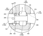
- FIG. 4 is a cross-sectional view showing the travel control valve unit of the valve device according to the first embodiment of the present invention, in which the main spool is at a position at the final stage of movement, and is meter-in via a first notch as a communication portion. This shows a state in which the outlet passage downstream of the throttle communicates with the traveling communication passage.
- FIG. 5A is an enlarged cross-sectional view showing a part of a travel control valve unit of a valve device according to a second embodiment of the present invention, in a state where a main spool is at a neutral position.
- FIG. 5B is an enlarged cross-sectional view showing a part of the travel control valve unit of the valve device according to the second embodiment of the present invention in an enlarged manner, and shows a state where the main spool has moved a predetermined distance X1 from the neutral position.
- FIG. 6A is an enlarged cross-sectional view showing a part of a travel control valve unit of a valve device according to a second embodiment of the present invention, and shows a state where a main spool has moved a predetermined distance X2 from a neutral position.
- FIG. 6B is an enlarged sectional view showing a part of the travel control valve unit of the valve device according to the second embodiment of the present invention in an enlarged manner, and shows a state where the main spool has moved from the neutral position by a predetermined distance X3.
- FIG. 7 is an enlarged cross-sectional view showing a part of a travel control valve unit of a valve device according to a modification of the second embodiment of the present invention. Show.
- valve device is mounted on a working machine, such as a construction machine, an agricultural machine, or an industrial machine, provided with a traveling device.
- a valve device mounted on a crawler-type hydraulic excavator as a working machine will be described as an example.
- hydraulic fluid is used as a working fluid for driving an actuator of a work machine.
- another fluid such as working water may be used as the working fluid.
- the hydraulic shovel includes a traveling unit, a turning unit provided to be able to turn above the traveling unit, and an excavation unit provided in the turning unit.
- the traveling unit has a pair of right and left crawlers.
- the pair of left and right crawlers is driven by left and right traveling motors, which will be described later, so that the hydraulic excavator travels.
- the excavating unit includes a boom rotatably attached to the turning unit, an arm rotatably attached to the boom, and a bucket rotatably attached to the arm.
- FIG. 1 is a hydraulic circuit diagram showing a configuration of the valve device 100.
- a hydraulic excavator includes a traveling unit, a turning unit, and a hydraulic pump driven by an engine, a pump 110 serving as a fluid pressure pump that discharges hydraulic oil, and hydraulic oil discharged from the pump 110.
- Examples of the plurality of actuators include a traveling motor 111 (a left traveling motor 111L and a right traveling motor 111R), which is a hydraulic motor for driving the traveling unit, a hydraulic motor (not shown) for driving the turning unit, and a hydraulic cylinder for driving the boom. (Not shown), a hydraulic cylinder for driving the arm (not shown), a hydraulic cylinder for driving the bucket (not shown), and the like.
- the pump 110 is a variable displacement piston pump, and the displacement of the pump 110 is changed by changing the inclination of the swash plate 110b by the regulator 110a.
- the discharge capacity of the pump 110 is set so that the differential pressure between the discharge pressure of the pump 110 guided to the regulator 110a and the maximum load pressure of each actuator (the highest load pressure among the load pressures of a plurality of actuators) becomes a predetermined value. Is controlled by so-called load sensing control.
- the valve device 100 includes a plurality of valve units, and controls the operation of each actuator by an actuator control valve incorporated in each valve unit.
- the valve device 100 will be described in detail with reference to FIG.
- the housing of the valve device 100 is formed by stacking and fastening the valve bodies of each valve unit.
- the valve body of each valve unit is formed in a rectangular parallelepiped shape.
- the valve body constituting the housing of the valve device 100 includes a valve block B which is a valve body in which each actuator control valve is incorporated, an inlet block IB which is a valve body for taking in hydraulic oil, and the like. Note that the inlet block IB is also an outlet block OB for discharging hydraulic oil to the tank 119.
- Each valve body (IB, B) is provided with a supply passage 121 to which hydraulic oil discharged from the pump 110 is supplied and a discharge passage 129 communicating with the tank 119.
- a relief valve 109 and an unload valve 108 interposed between the supply passage 121 and the discharge passage 129 are incorporated.
- the relief valve 109 regulates the maximum discharge pressure of the pump 110 and protects the hydraulic circuit.
- the unload valve 108 guides the hydraulic oil discharged from the pump 110 to the tank 119 when each actuator is not operating, and causes the pump 110 to perform a no-load operation (unload).
- Each valve block B incorporates an actuator control valve for controlling the flow of hydraulic oil supplied from the pump 110 to the actuator, and a pressure compensating valve associated with the actuator control valve.
- a travel control valve 131 (a left travel control valve 131L and a right travel control valve 131R), which is an actuator control valve for driving the travel motor 111 (a left travel motor 111L and a right travel motor 111R), and a travel control valve
- the traveling control valve unit 130 (the left traveling control valve unit 130L and the right traveling control valve unit 130R) in which the pressure compensating valve 140 associated with 131 is incorporated is illustrated.
- FIG. 1 the illustration of a valve unit in which an actuator control valve for controlling an actuator such as a boom, an arm, and a bucket is incorporated is simplified or omitted.
- Each actuator control valve is switched by a pilot pressure output in response to operation of an operation lever (not shown).
- the hydraulic system of the present embodiment employs an after-orifice type load sensing system in which a pressure compensating valve 140 is provided downstream of the meter-in throttle 134 of each actuator control valve.
- a pressure compensating valve 140 is provided downstream of the meter-in throttle 134 of each actuator control valve.
- the pressure compensating valve 140 functions as a load adjustment between the actuators.
- the pressure compensating valve 140 is provided with the pressure downstream of the meter-in throttle 134 provided in the actuator control valve and the maximum load pressure of each actuator (the highest load pressure among the load pressures of a plurality of actuators). You.
- the pressure compensating valve 140 compensates for the pressure downstream of the meter-in throttle 134 to be higher than the maximum load pressure of each actuator by a predetermined value. Therefore, in the hydraulic system according to the present embodiment, when simultaneously driving a plurality of actuator control valves, regardless of the magnitude of the load pressure of the actuator, hydraulic fluid is supplied at a flow rate corresponding to the operation amount of the spool of the actuator control valve. be able to.
- a left travel control valve 131L that controls the flow of hydraulic oil supplied from the pump 110 to the left travel motor 111L is incorporated in the valve block B1.
- a left traveling control valve unit 130L having the valve block B1 and the left traveling control valve 131L is configured.
- the left traveling motor 111L is a hydraulic motor that drives a crawler (not shown) on the left side of the hydraulic shovel.
- a right travel control valve 131R that controls the flow of hydraulic oil supplied from the pump 110 to the right travel motor 111R is incorporated in the valve block B2 adjacent to the valve block B1.
- a right traveling control valve unit 130R including the valve block B2 and the right traveling control valve 131R is configured.
- the right running motor 111R is a hydraulic motor that drives a right crawler (not shown) of the hydraulic shovel.
- the left traveling control valve unit 130L and the right traveling control valve unit 130R are arranged adjacent to each other, and are stacked together with the other valve units, thereby configuring the valve device 100. .
- the left traveling control valve unit 130L and the right traveling control valve unit 130R have the same configuration, and have a substantially plane-symmetric shape with respect to their contact surfaces.
- the travel control valve 131 rotates the travel motor 111 to the neutral position (N) for stopping the travel motor 111, the forward position (F) which is an operating position for rotating the travel motor 111 to one side, and the other.
- the pilot-operated directional control valve is switched between a retracted position (R), which is an operating position for the pilot valve.
- FIG. 2 is a cross-sectional view showing the travel control valve unit 130 of the valve device 100, and shows a state where the main spool 170 is at a neutral position (N).
- Each of the left and right travel control valve units 130L, 130R is a main in which a meter-in throttle 134 (see FIG. 1) provided between the pump 110 and the travel motor 111 and a spool that moves in the axial direction based on a travel operation command. It has a spool 170, a compensator spool 180 that moves in a direction perpendicular to the axial direction of the main spool 170, and a valve block B that houses the main spool 170 and the compensator spool 180.
- the valve block B is provided with a main housing hole 150 for slidably housing the main spool 170 and a sub housing hole 160 for slidably housing the compensator spool 180.
- the traveling operation command is a pilot pressure output from a pilot pressure output unit (not shown) to a first pilot pressure chamber 135a or a second pilot pressure chamber 135b, which will be described later, according to the operation amount of a traveling operation lever (not shown).
- valve block B and the main spool 170 are substantially symmetrical.
- the travel control valve 131 includes a main spool 170, a first pilot pressure chamber 135 a and a second pilot pressure chamber 135 b for controlling driving of the main spool 170, and a centering spring for urging the main spool 170 toward the axial center thereof. 137.
- the main spool 170 has a centering spring when the first pilot pressure chamber 135a and the second pilot pressure chamber 135b are connected to the tank 119 and no pilot pressure is applied to the first pilot pressure chamber 135a and the second pilot pressure chamber 135b. It is held at the neutral position (N) by the urging force of 137.
- the main spool 170 is switched to the forward position (F)
- the pilot pressure acts on the second pilot pressure chamber 135b
- the main spool 170 is switched to the retreat position (R).
- the valve block B has a supply passage 121 (see FIG. 1) through which hydraulic oil discharged from the pump 110 is supplied, a pair of supply branch passages 121 a and 121 b branched from the supply passage 121, and a downstream side of the meter-in throttle 134. And a pair of lead-out passages 123 (a first lead-out passage 123A and a second lead-out passage 123B) that constitute a passage on the upstream side of the pressure compensation valve 140 and a passage on the downstream side of the pressure compensation valve 140. And a first traveling communication passage 124A (see FIGS.
- a second traveling communication passage 124B (which communicates the second outlet passage 123B of the valve unit 130L with the second outlet passage 123B of the right traveling control valve unit 130R). 1), a pair of actuator passages 125 (first actuator passage 125A and second actuator passage 125B) communicating with the travel motor 111, a discharge passage 129 communicating with the tank 119, and a plurality of valves controlled by the valve device 100. And a load pressure passage 128 (see FIG. 1) through which the highest load pressure among the actuators is guided.
- the pair of lead-out passages 123 constitutes a so-called bridge passage having a bridge shape.
- the pair of lead-out passages 123 are provided on the downstream side of the meter-in throttle 134 and guide the hydraulic oil supplied from the supply passage 121 to the actuator passage 125.
- the traveling communication passage 124 (the first traveling communication passage 124A and the second traveling communication passage 124B) shown in FIGS. 1 and 4 is provided between the outlet passages 123 of the left and right traveling control valve units 130L and 130R (the first outlet passages 123A are connected to each other). And the second outlet passage 123B), and is provided to make the flow rates of the hydraulic oil supplied to the left and right traveling motors 111 equal.
- the traveling communication passage 124 extends in the width direction of the valve block B (the direction perpendicular to the plane of FIG. 4).
- a throttle 124c is provided in the traveling communication passage 124 of the right traveling control valve unit 130R to provide resistance to the passing hydraulic oil.
- the throttle 124c may be provided in the traveling communication passage 124 of the left traveling control valve unit 130L, or in both the traveling communication passage 124 of the left traveling control valve unit 130L and the traveling communication passage 124 of the right traveling control valve unit 130R. It may be provided.
- a plurality of annular concave portions 151, 152, 153, 154, 155 connected to the passages 122, 121 a, 121 b, 124, 123, 125, 129 are formed on the inner peripheral surface of the main housing hole 150. , 159 are provided.
- the introduction passage 122 is connected to the annular recess 151 provided at the axial center of the main housing hole 150 and the sub housing hole 160.
- the pair of supply branch passages 121a and 121b are connected to a pair of annular recesses 152 provided so as to sandwich the annular recess 151.
- the pair of traveling communication passages 124 is connected to a pair of annular recesses 153 provided so as to sandwich the pair of annular recesses 152.
- the pair of outlet passages 123 is connected to a pair of annular recesses 154 provided so as to sandwich the pair of annular recesses 153.
- the pair of actuator passages 125 are connected to a pair of annular recesses 155 provided so as to sandwich the pair of annular recesses 154.
- the discharge passage 129 is connected to a pair of annular recesses 159 provided so as to sandwich the pair of annular recesses 155.
- the pair of actuator passages 125 (the first actuator passage 125A and the second actuator passage 125B) form a pair of actuator ports 126 (the first actuator port 126A and the second actuator port 126B) opening on the outer peripheral surface of the valve block B.
- the annular recess 155 is connected.
- a compensator spool 180 is interposed between the pair of outlet passages 123 forming the bridge passage.
- An annular recess 161 connected to the pair of lead-out passages 123 is provided on the inner peripheral surface of the sub housing hole 160. That is, the outlet passage 123 has one end communicating with the main housing hole 150 and the other end communicating with the sub housing hole 160.
- the main spool 170 has a plurality of columnar lands that are in sliding contact with the inner peripheral surface of the main housing hole 150.
- a first supply-side land 171A and a second supply-side land 171B which are a pair of supply-side lands 171 provided at the axial center of the main spool 170, and a pair of supply-side lands.
- a first lead-out land portion 172A and a second lead-out land portion 172B that are a pair of lead-out land portions 172 provided so as to sandwich the portion 171 and a pair of discharge-side lands provided so as to sandwich the pair of lead-out land portions 172.
- Each land portion is configured such that a first discharge side land portion 173A, a first outlet side land portion 172A, a first supply side land portion 171A, The second supply land 171B, the second outlet land 172B, and the second discharge land 173B are provided in this order.
- the supply-side land portion 171 is a land portion that connects or blocks the supply passage 121 and the introduction passage 122.
- the pair of supply-side land portions 171 are configured to be able to block the pair of supply branch passages 121a and 121b by their outer peripheral surfaces.
- the lead-out side land portion 172 is a land portion that connects or disconnects the lead-out passage 123 and the actuator passage 125, and a land portion that connects or disconnects the lead-out passage 123 and the traveling communication passage 124.
- the pair of lead-out land portions 172 are configured to be able to block the pair of lead-out passages 123 by their outer peripheral surfaces.
- the discharge-side land portion 173 is a land portion that connects or blocks the actuator passage 125 and the discharge passage 129.
- the pair of discharge-side lands 173 is configured so that the discharge passage 129 can be shut off by the outer peripheral surfaces thereof.
- a first annular groove 176A is provided between the first outlet side land portion 172A and the first discharge side land portion 173A.
- a second annular groove 176B is provided between the second lead-out land 172B and the second discharge-side land 173B.
- the first annular groove 176A and the second annular groove 176B are also collectively referred to as an annular groove 176.
- a central annular groove 175 is provided between the first supply side land 171A and the second supply side land 171B.
- the central annular groove 175 is provided so as to face the introduction passage 122 and always communicates with the introduction passage 122.
- the first annular groove 176A is provided to face the first actuator passage 125A, and always communicates with the first actuator passage 125A.
- the second annular groove 176B is provided so as to face the second actuator passage 125B, and always communicates with the second actuator passage 125B.
- a plurality of first central notches 191A are provided on the first supply side land portion 171A so as to be spaced apart in the circumferential direction.
- the first central notch 191A extends in the axial direction of the main spool 170, and opens to the outer peripheral surface and the central annular groove 175 of the first supply-side land portion 171A.
- a plurality of second central notches 191B are provided in the second supply side land portion 171B so as to be spaced apart in the circumferential direction.
- the second central notch 191B extends in the axial direction of the main spool 170, and opens to the outer peripheral surface and the central annular groove 175 of the second supply-side land 171B.
- a plurality of first notches 192A are provided on the first outlet side land portion 172A so as to be spaced apart in the circumferential direction.
- the first notch 192A extends in the axial direction of the main spool 170, and opens to the outer peripheral surface of the first outlet side land portion 172A and the first annular groove 176A.
- a plurality of second notches 192B are provided in the second outlet side land portion 172B so as to be spaced apart in the circumferential direction.
- the second notch 192B extends in the axial direction of the main spool 170, and opens to the outer peripheral surface of the second outlet side land portion 172B and the second annular groove 176B.
- the compensator spool 180 is arranged so that one end (the lower end in the figure) faces the introduction passage 122 and the other end (the upper end in the figure) faces the maximum load pressure chamber 185.
- the maximum load pressure chamber 185 is a pressure chamber that communicates with the load pressure passage 128 (see FIG. 1) and into which the maximum load pressure of each actuator is led.
- the compensator spool 180 is provided with a throttle portion 181 that imparts resistance to the passing hydraulic oil at an initial stage when the compensator spool 180 moves to the maximum load pressure chamber 185 side.
- the degree of opening of the throttle portion 181 relative to the annular concave portion 161 increases as the compensator spool 180 moves toward the maximum load pressure chamber 185.
- the compensator spool 180 is provided with a pressure introducing portion 182 whose opening degree with respect to the annular concave portion 161 is variable according to the moving position.
- a groove is formed around the opening of the pressure introducing portion 182 on the side of the annular recess 161, and in the process of moving the groove relative to the annular recess 161, the substantial opening degree of the pressure introducing portion 182 with respect to the annular recess 161 is increased.
- the high-pressure selection valve 183 is incorporated in the compensator spool 180.
- the high-pressure selection valve 183 is arranged such that one end (the lower end in the drawing) faces the pressure introducing chamber 184 communicating with the pressure introducing portion 182, and the other end (the upper end in the drawing) faces the maximum load pressure chamber 185.
- the high-pressure selection valve 183 maintains the closed state when the pressure in the maximum load pressure chamber 185, that is, the maximum load pressure of each actuator is higher than the pressure in the pressure introduction chamber 184.
- the high-pressure selection valve 183 opens when the pressure in the pressure introduction chamber 184 is higher than the pressure in the maximum load pressure chamber 185, and guides the pressure in the pressure introduction chamber 184 to the load pressure passage 128 (see FIG. 1).
- FIGS. 3 and 4 are cross-sectional views showing the travel control valve unit 130 of the valve device 100, similarly to FIG.
- FIG. 3 shows a state in which the main spool 170 is at a position at the initial stage of movement, and a part of the hydraulic oil is discharged to the tank 119 from the second notch 192B serving as a discharge portion (bleed-off throttle).
- FIG. 4 shows a state in which the main spool 170 is located at the final stage of movement, and the outlet passage 123 downstream of the meter-in throttle 134 communicates with the traveling communication passage 124 via the first notch 192A as a communication portion. Is shown.
- a pilot pressure as a traveling operation command acts on the first pilot pressure chamber 135a or the second pilot pressure chamber 135b of the traveling control valve 131. I do.
- the operator Inclines the left traveling operation lever to the forward side and the right traveling operation lever to the forward side.
- the operation of the valve device 100 when the left and right traveling operation levers (not shown) are simultaneously operated to the forward side to make the hydraulic shovel (vehicle) travel straight the operation of the main spool 170 and the compensator spool 180, and The flow of the hydraulic oil in the travel control valve unit 130 will be described in detail.
- the first actuator passage 125A and the discharge passage 129 communicate with each other via the first annular groove 176A, and the second actuator passage 125B and the discharge passage 129 communicate with the second actuator passage 125B. It communicates via the annular groove 176B.
- the first actuator passage 125A and the second actuator passage 125B are formed by a first annular groove 176A, a first notch 192A, and a pair of outlet passages 123 forming a bridge passage.
- the second notch 192B and the second annular groove 176B are formed by a first annular groove 176A, a first notch 192A, and a pair of outlet passages 123 forming a bridge passage.
- a pilot pressure acts on the first pilot pressure chamber 135a, and the main spool 170 starts moving in the axial direction from the neutral position (N) to one side (left side in the figure). I do.
- the supply branch passage 121b and the introduction passage 122 communicate with each other through the second central notch 191B.
- the communication opening at this time constitutes the meter-in stop 134 shown in FIG.
- the pressure of the hydraulic oil guided to the introduction passage 122 becomes lower than the pump discharge pressure by a pressure loss corresponding to the opening of the meter-in throttle 134.
- the hydraulic oil guided to the first actuator passage 125A is supplied to the traveling motor 111 through the first actuator port 126A, and the traveling motor 111 rotates.
- the operating oil discharged from the traveling motor 111 is guided to the second actuator passage 125B through the second actuator port 126B.
- the hydraulic oil guided to the second actuator passage 125B is guided to the discharge passage 129 through the second annular groove 176B, and is discharged to the tank 119.
- the supply passage 121 passes through the introduction passage 122 through the introduction passage 123. Is supplied to the first actuator passage 125A through the first annular groove 176A, and the traveling motor 111 rotates.
- the second outlet passage 123B communicates with the second annular groove 176B via the second notch 192B. For this reason, as indicated by the dashed arrow in the drawing, part of the hydraulic oil guided from the supply passage 121 to the outlet passage 123 through the introduction passage 122 is transferred to the discharge passage 129 through the second notch 192B and the second annular groove 176B. Is discharged.
- the main spool 170 of the traveling control valve unit 130 moves in response to the traveling operation command, a part of the hydraulic oil supplied from the supply passage 121 is discharged to the discharge section at an initial stage of the movement. It is discharged from the second notch 192B functioning as (bleed-off stop). Therefore, immediately after the start of the operation of the travel operation lever, the hydraulic oil is prevented from flowing abruptly to the travel motor 111, and the start of the travel motor 111 in response to the travel operation command can be made smooth. That is, according to the present embodiment, it is possible to prevent the vehicle body from shaking or shock at the start of traveling, and to improve the traveling performance at the start of traveling.
- the movement of the main spool 170 is reversed from the above-described movement, and the first notch 192A shown in FIG. 2 functions as a discharge unit (bleed-off aperture). That is, when the main spool 170 moves from the neutral position (N) to the other side in the axial direction, at the initial stage of the movement, the hydraulic oil guided from the supply passage 121 to the outlet passage 123 passes through the second annular groove 176B and the second actuator passage 125B. And a part of the hydraulic oil guided from the supply passage 121 to the outlet passage 123 is discharged to the discharge passage 129 through the first notch 192A as a discharge part. Therefore, even when the vehicle is moving backward, the start of the traveling motor 111 in response to the traveling operation command can be made smooth, and the traveling performance at the start of traveling can be improved.
- the traveling communication path 124 when the traveling communication path 124 is not provided, if there is a processing error in the left and right traveling control valves 131L, 131R, the pressure compensating valve 140, etc., the hydraulic oil supplied to the left and right traveling motors 111L, 111R is biased. Is generated, and there is a possibility that the traveling may bend.
- the first notch 192A as a communication portion provided in the lead-out land portion 172 is provided.
- the outlet passage 123 and the traveling communication passage 124 communicate with each other via the. Therefore, the flow rate to one of the left and right travel motors 111L and 111R is larger than the flow rate to the other due to the processing error in the left and right travel control valves 131L and 131R, the pressure compensation valve 140, and the like.
- part of the hydraulic oil is guided from one circuit of the left and right traveling motors 111L and 111R to the other circuit through the traveling communication path 124. Thereby, the flow rate of the hydraulic oil is adjusted such that the flow rates of the hydraulic oil supplied to the left and right traveling motors 111L and 111R are the same.
- the main spool 170 of the left and right traveling control valve units 130L and 130R moves, the main spool 170 is moved.
- the lead-out passages 123 downstream of the meter-in throttle 134 in the left and right traveling control valve units 130L and 130R communicate with each other via a first notch 192A as a communication part. For this reason, it is possible to suppress variation in the supply flow rate of the working oil to the left and right traveling motors 111L and 111R. In other words, according to the present embodiment, it is possible to prevent the traveling bending from occurring when the left and right traveling operation levers are maximally operated to the forward side, and to improve traveling performance during straight traveling.
- the movement of the main spool 170 is reversed from the above-described movement, and the second notch 192B shown in FIG. 2 functions as a communication part. That is, when the main spool 170 moves from the neutral position (N) to the other side in the axial direction, at the final stage of the movement, the lead-out passage 123 and the traveling communication passage 124 communicate with each other through the second notch 192B as a communication portion.
- the outlet passages 123 in the left and right traveling control valve units 130L and 130R communicate with each other. For this reason, even when the vehicle retreats, the straight traveling performance can be improved.
- the main spool 170 moves from the neutral position (N) to one side, at the final stage of the movement, the main spool 170 is provided with a communication portion that communicates the lead-out passage 123 with the traveling communication passage 124.
- the first notch 192A functions as a communication part
- the second notch 192B functions as a communication part.
- the second notch 192B functions as a discharge unit at the initial stage of movement
- the first notch 192A functions as a communication unit at the final stage of movement.
- the first notch 192A functions as a discharge unit in an initial stage of movement
- the second notch 192B functions as a communication unit in a final stage of movement.
- one type of notch 192A, 192B provided on the outlet side land portion 172 functions as a communication portion that connects the outlet passage 123 and the traveling communication passage 124, and also connects the outlet passage 123 and the discharge passage 129. It also has a function as a discharge unit (bleed-off aperture).
- FIGS. 5A, 5B, 6A, and 6B A valve device according to a second embodiment of the present invention will be described with reference to FIGS. 5A, 5B, 6A, and 6B.
- description will be made focusing on points different from the first embodiment, and in the drawings, the same or corresponding components as those described in the first embodiment will be denoted by the same reference numerals and description thereof will be omitted.
- . 5A to 6B are enlarged sectional views showing a part of the travel control valve unit in an enlarged manner.
- FIG. 5A shows a state where the main spool 270 is at the neutral position (N)
- FIG. 5B shows a state where the main spool 270 has moved a predetermined distance X1 from the neutral position (N).
- FIG. 6A shows a state where the main spool 270 has moved a predetermined distance X2 from the neutral position (N)
- FIG. 6B shows a state where the main spool 270 has moved a predetermined distance X3 from the neutral position (N).
- one type of notch 192A, 192B provided in the outlet side land portion 172 functions as a communication portion that connects the outlet passage 123 and the traveling communication passage 124, and the outlet passage 123 and the discharge passage 129. It also has a function as a discharge section (bleed-off aperture) that communicates with.
- the notch 295 provided in the discharge-side land portion 173 has the concave portion 295 provided in the discharge-side land portion 172 serving as a communication portion that connects the discharge passage 123 and the traveling communication passage 124.
- 296 functions as a discharge unit (bleed-off restriction) that connects the discharge passage 123 and the discharge passage 129. The details will be described below.
- the main spool 270 is provided with an annular groove 176 between the lead-out land portion 172 and the discharge-side land portion 173 as in the first embodiment.
- the notch 296 as a discharge portion (bleed-off stop) is provided in the discharge-side land portion 173 so as to be spaced apart in the circumferential direction.
- Notch 296 is provided to extend in the axial direction of main spool 270.
- the notch 296 is provided on the discharge side land portion 173 so as to open to the outer peripheral surface and the annular groove 176.
- the concave portion 295 as the communication portion is provided in the lead-out side land portion 172 so as to be spaced apart in the circumferential direction.
- the concave portion 295 is provided in the outlet side land portion 172 so as to open on the outer peripheral surface thereof and not to open in the annular groove 176.
- the concave portion 295 is formed in a racing track shape in which both ends of two sides parallel to the axial direction of the main spool 270 are connected by an arc.
- a plurality of notches 297 are provided on the lead-out side land portion 172 so as to be spaced apart in the circumferential direction.
- the notch 297 extends in the axial direction of the main spool 270 and opens in the outer peripheral surface of the outlet side land portion 172 and the annular groove 176.
- the main spool 270 is held at the neutral position (N).
- the communication between the supply passage 121 and the introduction passage 122 is interrupted by the supply land portion 171 as in the first embodiment (see FIG. 2).
- the actuator passage 125 and the discharge passage 129 communicate with each other via the annular groove 176.
- the supply branch passage 121b and the introduction passage 122 are connected to the second passage as in the first embodiment. They communicate via a central notch 191B (see FIG. 3).
- the first annular groove 176A communicates with the discharge passage 129 via the notch 296. For this reason, as shown by the dashed arrow in FIG. 5B, a part of the hydraulic oil guided from the supply passage 121 to the outlet passage 123 through the introduction passage 122 is discharged to the discharge passage 129 through the first annular groove 176A and the notch 296. You.
- the first derivation is performed as shown in FIG. 6B.
- the passage 123A and the first traveling communication passage 124A communicate with each other via a concave portion 295 provided in the first outlet side land portion 172A.
- the first travel communication path 124A of the left travel control valve unit 130L and the first travel communication path 124A of the right travel control valve unit 130R communicate. I do.
- the lead-out passage 123 and the traveling communication passage are provided via the concave portion 295 as a communication portion provided in the lead-out land portion 172. And 124. Therefore, when there is a processing error in the left and right travel control valves 131L, 131R, the pressure compensating valve 140, and the like, the flow rate of the hydraulic oil supplied to the left and right travel motors 111L, 111R is the same. Is adjusted.
- the concave portion 295 is provided in the outlet side land portion 172 as a communication portion that connects the outlet passage 123 and the traveling communication passage 124. Therefore, by adjusting the axial length of the concave portion 295, the timing at which the outlet passages 123 of the left and right traveling control valve units 130 communicate with each other can be set more appropriately.
- the discharge side land portion 173 is provided with a notch 296 as a discharge portion (bleed-off restriction) that connects the discharge passage 123 and the discharge passage 129.
- a notch 296 as a discharge portion (bleed-off restriction) that connects the discharge passage 123 and the discharge passage 129.
- the timing for closing the opening of the bleed-off aperture and the timing for starting the communication between the lead-out passage 123 and the traveling communication passage 124 can be individually set, so that the traveling performance of the vehicle is improved.
- the degree of freedom of adjustment is high.
- the notch 297 provided on the outlet side land portion 172 can control the timing at which the outlet passage 123 and the actuator passage 125 communicate with each other. Therefore, by adjusting the axial length of the notch 297, the start timing of the traveling motor 111 can be set more appropriately.
- the discharge portion provided in the discharge side land portion 173 is not limited to the notch 296 described in the second embodiment.
- the discharge unit may be configured by a plurality of passages.
- the discharge portion 396 communicating the discharge passage 123 and the discharge passage 129 has a first discharge passage 396a communicating with the annular groove 176, and a second discharge passage 396a communicating with the first discharge passage 396a and opening on the outer peripheral surface of the discharge side land portion 173. And a discharge path 396b.
- the second discharge path 396b extends in the radial direction of the main spool 370.
- the hydraulic oil discharged into the discharge passage 129 through the discharge portion 396 is radially outward from the opening end of the second discharge passage 396b, that is, in a direction orthogonal to the axial direction of the main spool 370. Is discharged.
- the hydraulic oil flows from the notch 296 toward the discharge passage 129 along the axial direction of the main spool 270 as indicated by the broken arrow in FIG. 5B. Fluid force is generated to hinder movement.
- the hydraulic oil flows from the discharge portion 396 shown in FIG. 7 toward the discharge passage 129 in a direction orthogonal to the axial direction of the main spool 270. Since the hydraulic oil is discharged in the radial direction from the second discharge path 396b of the discharge side land portion 173, it is possible to suppress the generation of the fluid force that hinders the axial movement of the main spool 370. That is, it is possible to suppress that the movement of the main spool 370 in the axial direction is hindered by the hydraulic oil flowing from the discharge portion 396 to the discharge passage 129.
- ⁇ Modification 1> In the first embodiment, a description will be given of an example in which a discharge portion (notches 192A and 192B) for controlling the bleed-off flow rate is provided in the lead-out land portion 172. Although the example provided in the unit 173 has been described, the present invention is not limited to this. A discharge unit may be provided in both the lead-out land unit 172 and the discharge-side land unit 173.
- the valve device 100 includes a left and right travel control valve unit 130 that controls the flow of the working fluid supplied from the fluid pressure pump (pump 110) to the left and right travel motors 111.
- Each of units 130 has a spool (main spool 170, 270, 370) that moves in the axial direction based on a traveling operation command, and a valve body (valve) that slidably accommodates the spool (main spool 170, 270, 370).
- valve body includes a supply passage 121 to which a working fluid discharged from a hydraulic pump (pump 110) is supplied, an actuator passage 125 communicating with the traveling motor 111, The working fluid supplied from the discharge passage 129 communicating with the tank 119 and the supply passage 121 is actuated. And a communication passage (running communication passage 124) that communicates the outflow passages 123 of the left and right traveling control valve units 130 with each other.
- the spools main spools 170, 270, and 370
- first notch 192A that communicates between the lead-out passage 123 and the communication passage (running communication passage 124).
- a second notch 192B, and a concave portion 295) are provided.
- the outlet passages 123 in the left and right traveling control valve units 130 communicate with each other through the communicating portions (the first notch 192A, the second notch 192B, the concave portion 295). Variations in the supply flow rate of the working fluid can be suppressed. This makes it possible to improve the traveling performance at the start of traveling and at the time of straight traveling.
- the improvement of the traveling performance is achieved by the discharge portions (first notch 192A, second notch 192B, notch 296, discharge portion 396) provided on the spool (main spool 170, 270, 370) and the communication portion (first notch). 192A, the second notch 192B, and the concave portion 295).
- the discharge portions first notch 192A, second notch 192B, and the concave portion 295).
- the spool (main spool 170) includes a first outlet side land portion 172 ⁇ / b> A and a second outlet side land portion 172 ⁇ / b> B as a pair of outlet side land portions 172, and a first outlet side land portion 173.
- a second annular groove 176B provided between the first discharge side land portion 173B and the first discharge side land portion 173B.
- the first outlet side land portion 172A is provided with a first notch 192A opening to the first annular groove 176A.
- the second outlet side land portion 172B is provided with a second notch 192B that opens into the second annular groove 176B, and the valve body (valve block B) is connected to the first annular groove 176.
- a second actuator passage 125B as the actuator passage 125 communicating with the second annular groove 176B.
- the spool (main spool 170) is moved from the neutral position to one end.
- the working fluid led from the supply passage 121 to the lead-out passage 123 is supplied to the first actuator passage 125A through the first annular groove 176A, and is also led from the supply passage 121 to the lead-out passage 123.
- a part of the working fluid is discharged to the discharge passage 129 through the second notch 192B as a discharge part, and when the spool (main spool 170) moves from the neutral position to one side, at the final stage of the movement, the first part as the communication part Outlet passage 12 through one notch 192A
- the working fluid guided from the supply passage 121 to the outlet passage 123 is in the initial stage of the movement when the spool (main spool 170) moves from the neutral position to the other.
- the second notch 192B functions as a discharge unit at the initial stage of movement
- the first notch 192A functions as a communication unit at the final stage of movement.
- the first notch 192A functions as a discharge unit in an initial stage of movement
- the second notch 192B functions as a communication unit in a final stage of movement. That is, by making the notches 192A and 192B formed in the outlet side land portion 172 function as the discharge portion and the communication portion, the traveling performance at the time of starting and the traveling performance at the time of going straight can be improved.
- the spools (main spools 270 and 370) have an annular groove 176 provided between the lead-out land portion 172 and the discharge-side land portion 173, and the discharge portions (notches 296 and discharge portions 396) are provided.
- the discharge side land portion 173 is provided so as to open to the outer peripheral surface thereof and the annular groove 176, and the communication portion (recess 295) opens to the outer peripheral surface thereof at the outlet side land portion 172 and opens to the annular groove 176. It is provided not to be.
- the discharge portions (notches 296 and discharge portions 396) provided on the discharge side land portion 173 supply the supply to the lead-out passage 123.
- the timing at which the discharge of a part of the fluid is stopped is controlled, and the timing at which the communication between the outlet passage 123 and the communication passage (running communication passage 124) is started by the communication portion (recess 295) provided on the outlet land portion 172. Can be controlled.
- the valve device 100 includes a first discharge path 396a in which the discharge portion 396 communicates with the annular groove 176, and a second discharge path 396b that communicates with the first discharge path 396a and opens on the outer peripheral surface of the discharge side land portion 173. And a second discharge path 396b extends in the radial direction of the spool (main spool 370).
- a notch 297 that opens into the annular groove 176 is provided in the outlet side land portion 172, and when the notch 297 moves the spool (main spool 270, 370) from the neutral position, the outlet passage 123 and the actuator passage And 125.
- the timing at which the lead-out passage 123 and the actuator passage 125 communicate with each other can be controlled by the notch 297.
Priority Applications (3)
| Application Number | Priority Date | Filing Date | Title |
|---|---|---|---|
| CN201980004830.2A CN111164315B (zh) | 2018-07-06 | 2019-05-15 | 阀装置 |
| US16/755,003 US10969026B2 (en) | 2018-07-06 | 2019-05-15 | Valve device |
| EP19831558.2A EP3677795B1 (en) | 2018-07-06 | 2019-05-15 | Valve device |
Applications Claiming Priority (2)
| Application Number | Priority Date | Filing Date | Title |
|---|---|---|---|
| JP2018-129127 | 2018-07-06 | ||
| JP2018129127A JP6600386B1 (ja) | 2018-07-06 | 2018-07-06 | 弁装置 |
Publications (1)
| Publication Number | Publication Date |
|---|---|
| WO2020008736A1 true WO2020008736A1 (ja) | 2020-01-09 |
Family
ID=68383333
Family Applications (1)
| Application Number | Title | Priority Date | Filing Date |
|---|---|---|---|
| PCT/JP2019/019363 WO2020008736A1 (ja) | 2018-07-06 | 2019-05-15 | 弁装置 |
Country Status (5)
| Country | Link |
|---|---|
| US (1) | US10969026B2 (zh) |
| EP (1) | EP3677795B1 (zh) |
| JP (1) | JP6600386B1 (zh) |
| CN (1) | CN111164315B (zh) |
| WO (1) | WO2020008736A1 (zh) |
Families Citing this family (4)
| Publication number | Priority date | Publication date | Assignee | Title |
|---|---|---|---|---|
| US11286962B2 (en) * | 2017-09-29 | 2022-03-29 | Volvo Construction Equipment Ab | Flow control valve and hydraulic machine including the same |
| JP6600386B1 (ja) * | 2018-07-06 | 2019-10-30 | Kyb株式会社 | 弁装置 |
| JP2023086306A (ja) * | 2021-12-10 | 2023-06-22 | Kyb株式会社 | 弁装置 |
| CN115285242B (zh) * | 2022-08-29 | 2023-08-22 | 三一重机有限公司 | 履带轮、履带行走装置及作业机械 |
Citations (4)
| Publication number | Priority date | Publication date | Assignee | Title |
|---|---|---|---|---|
| JP2006082767A (ja) | 2004-09-17 | 2006-03-30 | Hitachi Constr Mach Co Ltd | 走行式建設機械の油圧駆動装置 |
| JP2006336731A (ja) * | 2005-06-01 | 2006-12-14 | Shin Caterpillar Mitsubishi Ltd | 作業機械における走行用油圧制御装置 |
| JP2010151189A (ja) * | 2008-12-24 | 2010-07-08 | Kayaba Ind Co Ltd | 走行系の制御回路 |
| JP2018129127A (ja) | 2017-02-06 | 2018-08-16 | 株式会社デンソー | 燃料電池セルスタック |
Family Cites Families (28)
| Publication number | Priority date | Publication date | Assignee | Title |
|---|---|---|---|---|
| US2475298A (en) * | 1945-06-22 | 1949-07-05 | Goodman Mfg Co | Hydraulic control valve |
| GB1422938A (en) * | 1972-01-14 | 1976-01-28 | Sperry Rand Ltd | Hydraulic valves |
| US4238112A (en) * | 1978-12-22 | 1980-12-09 | Rexnord Inc. | Spool spin prevention for hydraulic control valves |
| PT70158A1 (en) * | 1980-03-03 | 1982-03-01 | Univ Miami | Process for preparing anti-hypertensive agents |
| KR100532176B1 (ko) * | 1998-09-30 | 2006-02-13 | 볼보 컨스트럭션 이키프먼트 홀딩 스웨덴 에이비 | 중장비의 주행직진 유압회로 |
| JP2005096704A (ja) * | 2003-09-26 | 2005-04-14 | Hitachi Constr Mach Co Ltd | 走行式建設機械の油圧駆動装置 |
| JP2005119619A (ja) * | 2003-10-20 | 2005-05-12 | Hitachi Constr Mach Co Ltd | 走行式建設機械の油圧駆動装置 |
| JP5543236B2 (ja) * | 2010-02-10 | 2014-07-09 | 東芝機械株式会社 | 建設機械の油圧制御弁 |
| JP5822232B2 (ja) * | 2012-03-02 | 2015-11-24 | Kyb株式会社 | 切換弁 |
| JP5809602B2 (ja) * | 2012-05-31 | 2015-11-11 | 日立建機株式会社 | 多連弁装置 |
| JP5984575B2 (ja) * | 2012-08-15 | 2016-09-06 | Kyb株式会社 | 切換弁 |
| JP6012021B2 (ja) * | 2012-11-07 | 2016-10-25 | Kyb株式会社 | パワーショベルの流体圧制御装置 |
| JP2014196810A (ja) * | 2013-03-29 | 2014-10-16 | 株式会社テージーケー | ステッピングモータ駆動式の制御弁 |
| JP6021226B2 (ja) * | 2013-11-28 | 2016-11-09 | 日立建機株式会社 | 建設機械の油圧駆動装置 |
| JP6307292B2 (ja) * | 2014-01-31 | 2018-04-04 | Kyb株式会社 | 作業機の制御システム |
| JP6305162B2 (ja) * | 2014-03-31 | 2018-04-04 | Kyb株式会社 | 弁装置 |
| JP6397715B2 (ja) * | 2014-10-06 | 2018-09-26 | Kyb−Ys株式会社 | 流体圧制御装置 |
| JP6440451B2 (ja) * | 2014-10-27 | 2018-12-19 | Kyb株式会社 | ロードセンシングバルブ装置 |
| JP6423754B2 (ja) * | 2015-04-24 | 2018-11-14 | Kyb株式会社 | 流量制御弁 |
| CN104791311B (zh) * | 2015-04-28 | 2017-01-04 | 湖南五新隧道智能装备股份有限公司 | 一种工程车辆液压行走控制系统 |
| JP6773418B2 (ja) * | 2015-09-28 | 2020-10-21 | ナブテスコ株式会社 | 方向切換弁及び油圧システム |
| JP6084264B1 (ja) * | 2015-09-28 | 2017-02-22 | Kyb株式会社 | スプール弁装置 |
| JP6647826B2 (ja) * | 2015-09-29 | 2020-02-14 | ナブテスコ株式会社 | 方向切換弁及び油圧システム |
| JP6773421B2 (ja) * | 2016-02-08 | 2020-10-21 | ナブテスコ株式会社 | 方向切換弁及び油圧システム |
| CN105736502B (zh) * | 2016-04-22 | 2018-08-28 | 泉州鑫豪工程机械科技有限公司 | 一种用于液压行走马达的平衡控制阀 |
| JP2017219123A (ja) * | 2016-06-08 | 2017-12-14 | Kyb株式会社 | スプール弁 |
| CN206723170U (zh) * | 2017-03-20 | 2017-12-08 | 东北林业大学 | 一种液压马达由两个换向阀控制完成不同工况的液压系统 |
| JP6600386B1 (ja) * | 2018-07-06 | 2019-10-30 | Kyb株式会社 | 弁装置 |
-
2018
- 2018-07-06 JP JP2018129127A patent/JP6600386B1/ja active Active
-
2019
- 2019-05-15 EP EP19831558.2A patent/EP3677795B1/en active Active
- 2019-05-15 WO PCT/JP2019/019363 patent/WO2020008736A1/ja unknown
- 2019-05-15 CN CN201980004830.2A patent/CN111164315B/zh active Active
- 2019-05-15 US US16/755,003 patent/US10969026B2/en active Active
Patent Citations (4)
| Publication number | Priority date | Publication date | Assignee | Title |
|---|---|---|---|---|
| JP2006082767A (ja) | 2004-09-17 | 2006-03-30 | Hitachi Constr Mach Co Ltd | 走行式建設機械の油圧駆動装置 |
| JP2006336731A (ja) * | 2005-06-01 | 2006-12-14 | Shin Caterpillar Mitsubishi Ltd | 作業機械における走行用油圧制御装置 |
| JP2010151189A (ja) * | 2008-12-24 | 2010-07-08 | Kayaba Ind Co Ltd | 走行系の制御回路 |
| JP2018129127A (ja) | 2017-02-06 | 2018-08-16 | 株式会社デンソー | 燃料電池セルスタック |
Non-Patent Citations (1)
| Title |
|---|
| See also references of EP3677795A4 |
Also Published As
| Publication number | Publication date |
|---|---|
| EP3677795A1 (en) | 2020-07-08 |
| US10969026B2 (en) | 2021-04-06 |
| EP3677795A4 (en) | 2021-07-21 |
| EP3677795B1 (en) | 2024-03-06 |
| CN111164315A (zh) | 2020-05-15 |
| JP6600386B1 (ja) | 2019-10-30 |
| US20200348699A1 (en) | 2020-11-05 |
| CN111164315B (zh) | 2021-12-10 |
| JP2020008085A (ja) | 2020-01-16 |
Similar Documents
| Publication | Publication Date | Title |
|---|---|---|
| WO2020008736A1 (ja) | 弁装置 | |
| US7305821B2 (en) | Hydraulic control apparatus | |
| JP6730798B2 (ja) | 油圧駆動装置 | |
| WO2014021015A1 (ja) | 建設機械の油圧駆動装置 | |
| EP3919786A1 (en) | Flow control valve | |
| JP7121642B2 (ja) | 流体圧制御装置 | |
| JP7090567B2 (ja) | 建設機械 | |
| JP7423189B2 (ja) | 制御弁及び建設機械用油圧システム | |
| JPH07103882B2 (ja) | 圧力補償付液圧弁 | |
| JP7360858B2 (ja) | 流体制御装置及び建設機械 | |
| US11339884B2 (en) | Valve device | |
| JP7026005B2 (ja) | 流体圧制御装置 | |
| JP3974076B2 (ja) | 液圧駆動装置 | |
| WO2023105872A1 (ja) | 弁装置 | |
| JP7121641B2 (ja) | 流体圧制御装置 | |
| JP7411417B2 (ja) | 油圧回路、油圧回路用の方向切換弁および建設機械 | |
| JP4933299B2 (ja) | 建設機械の油圧制御装置 | |
| WO2023189986A1 (ja) | 流量制御弁 | |
| WO2023189508A1 (ja) | 方向制御弁 | |
| JP2022166300A (ja) | 流量制御弁 | |
| JPH0255568B2 (zh) | ||
| JPH09210011A (ja) | 建機の油圧回路 |
Legal Events
| Date | Code | Title | Description |
|---|---|---|---|
| 121 | Ep: the epo has been informed by wipo that ep was designated in this application |
Ref document number: 19831558 Country of ref document: EP Kind code of ref document: A1 |
|
| ENP | Entry into the national phase |
Ref document number: 2019831558 Country of ref document: EP Effective date: 20200403 |
|
| NENP | Non-entry into the national phase |
Ref country code: DE |