WO2020008736A1 - Valve device - Google Patents
Valve device Download PDFInfo
- Publication number
- WO2020008736A1 WO2020008736A1 PCT/JP2019/019363 JP2019019363W WO2020008736A1 WO 2020008736 A1 WO2020008736 A1 WO 2020008736A1 JP 2019019363 W JP2019019363 W JP 2019019363W WO 2020008736 A1 WO2020008736 A1 WO 2020008736A1
- Authority
- WO
- WIPO (PCT)
- Prior art keywords
- passage
- discharge
- land portion
- spool
- notch
- Prior art date
Links
Images


Classifications
-
- F—MECHANICAL ENGINEERING; LIGHTING; HEATING; WEAPONS; BLASTING
- F16—ENGINEERING ELEMENTS AND UNITS; GENERAL MEASURES FOR PRODUCING AND MAINTAINING EFFECTIVE FUNCTIONING OF MACHINES OR INSTALLATIONS; THERMAL INSULATION IN GENERAL
- F16H—GEARING
- F16H61/00—Control functions within control units of change-speed- or reversing-gearings for conveying rotary motion ; Control of exclusively fluid gearing, friction gearing, gearings with endless flexible members or other particular types of gearing
- F16H61/38—Control of exclusively fluid gearing
- F16H61/40—Control of exclusively fluid gearing hydrostatic
- F16H61/44—Control of exclusively fluid gearing hydrostatic with more than one pump or motor in operation
- F16H61/456—Control of the balance of torque or speed between pumps or motors
-
- E—FIXED CONSTRUCTIONS
- E02—HYDRAULIC ENGINEERING; FOUNDATIONS; SOIL SHIFTING
- E02F—DREDGING; SOIL-SHIFTING
- E02F9/00—Component parts of dredgers or soil-shifting machines, not restricted to one of the kinds covered by groups E02F3/00 - E02F7/00
- E02F9/02—Travelling-gear, e.g. associated with slewing gears
-
- E—FIXED CONSTRUCTIONS
- E02—HYDRAULIC ENGINEERING; FOUNDATIONS; SOIL SHIFTING
- E02F—DREDGING; SOIL-SHIFTING
- E02F9/00—Component parts of dredgers or soil-shifting machines, not restricted to one of the kinds covered by groups E02F3/00 - E02F7/00
- E02F9/20—Drives; Control devices
- E02F9/22—Hydraulic or pneumatic drives
-
- F—MECHANICAL ENGINEERING; LIGHTING; HEATING; WEAPONS; BLASTING
- F15—FLUID-PRESSURE ACTUATORS; HYDRAULICS OR PNEUMATICS IN GENERAL
- F15B—SYSTEMS ACTING BY MEANS OF FLUIDS IN GENERAL; FLUID-PRESSURE ACTUATORS, e.g. SERVOMOTORS; DETAILS OF FLUID-PRESSURE SYSTEMS, NOT OTHERWISE PROVIDED FOR
- F15B11/00—Servomotor systems without provision for follow-up action; Circuits therefor
- F15B11/16—Servomotor systems without provision for follow-up action; Circuits therefor with two or more servomotors
- F15B11/22—Synchronisation of the movement of two or more servomotors
-
- F—MECHANICAL ENGINEERING; LIGHTING; HEATING; WEAPONS; BLASTING
- F16—ENGINEERING ELEMENTS AND UNITS; GENERAL MEASURES FOR PRODUCING AND MAINTAINING EFFECTIVE FUNCTIONING OF MACHINES OR INSTALLATIONS; THERMAL INSULATION IN GENERAL
- F16H—GEARING
- F16H61/00—Control functions within control units of change-speed- or reversing-gearings for conveying rotary motion ; Control of exclusively fluid gearing, friction gearing, gearings with endless flexible members or other particular types of gearing
- F16H61/38—Control of exclusively fluid gearing
- F16H61/40—Control of exclusively fluid gearing hydrostatic
- F16H61/4148—Open loop circuits
-
- F—MECHANICAL ENGINEERING; LIGHTING; HEATING; WEAPONS; BLASTING
- F16—ENGINEERING ELEMENTS AND UNITS; GENERAL MEASURES FOR PRODUCING AND MAINTAINING EFFECTIVE FUNCTIONING OF MACHINES OR INSTALLATIONS; THERMAL INSULATION IN GENERAL
- F16K—VALVES; TAPS; COCKS; ACTUATING-FLOATS; DEVICES FOR VENTING OR AERATING
- F16K11/00—Multiple-way valves, e.g. mixing valves; Pipe fittings incorporating such valves
- F16K11/02—Multiple-way valves, e.g. mixing valves; Pipe fittings incorporating such valves with all movable sealing faces moving as one unit
- F16K11/06—Multiple-way valves, e.g. mixing valves; Pipe fittings incorporating such valves with all movable sealing faces moving as one unit comprising only sliding valves, i.e. sliding closure elements
- F16K11/065—Multiple-way valves, e.g. mixing valves; Pipe fittings incorporating such valves with all movable sealing faces moving as one unit comprising only sliding valves, i.e. sliding closure elements with linearly sliding closure members
- F16K11/07—Multiple-way valves, e.g. mixing valves; Pipe fittings incorporating such valves with all movable sealing faces moving as one unit comprising only sliding valves, i.e. sliding closure elements with linearly sliding closure members with cylindrical slides
-
- F—MECHANICAL ENGINEERING; LIGHTING; HEATING; WEAPONS; BLASTING
- F16—ENGINEERING ELEMENTS AND UNITS; GENERAL MEASURES FOR PRODUCING AND MAINTAINING EFFECTIVE FUNCTIONING OF MACHINES OR INSTALLATIONS; THERMAL INSULATION IN GENERAL
- F16K—VALVES; TAPS; COCKS; ACTUATING-FLOATS; DEVICES FOR VENTING OR AERATING
- F16K27/00—Construction of housing; Use of materials therefor
-
- F—MECHANICAL ENGINEERING; LIGHTING; HEATING; WEAPONS; BLASTING
- F16—ENGINEERING ELEMENTS AND UNITS; GENERAL MEASURES FOR PRODUCING AND MAINTAINING EFFECTIVE FUNCTIONING OF MACHINES OR INSTALLATIONS; THERMAL INSULATION IN GENERAL
- F16K—VALVES; TAPS; COCKS; ACTUATING-FLOATS; DEVICES FOR VENTING OR AERATING
- F16K3/00—Gate valves or sliding valves, i.e. cut-off apparatus with closing members having a sliding movement along the seat for opening and closing
- F16K3/22—Gate valves or sliding valves, i.e. cut-off apparatus with closing members having a sliding movement along the seat for opening and closing with sealing faces shaped as surfaces of solids of revolution
- F16K3/24—Gate valves or sliding valves, i.e. cut-off apparatus with closing members having a sliding movement along the seat for opening and closing with sealing faces shaped as surfaces of solids of revolution with cylindrical valve members
-
- B—PERFORMING OPERATIONS; TRANSPORTING
- B60—VEHICLES IN GENERAL
- B60Y—INDEXING SCHEME RELATING TO ASPECTS CROSS-CUTTING VEHICLE TECHNOLOGY
- B60Y2200/00—Type of vehicle
- B60Y2200/40—Special vehicles
- B60Y2200/41—Construction vehicles, e.g. graders, excavators
- B60Y2200/412—Excavators
-
- F—MECHANICAL ENGINEERING; LIGHTING; HEATING; WEAPONS; BLASTING
- F16—ENGINEERING ELEMENTS AND UNITS; GENERAL MEASURES FOR PRODUCING AND MAINTAINING EFFECTIVE FUNCTIONING OF MACHINES OR INSTALLATIONS; THERMAL INSULATION IN GENERAL
- F16K—VALVES; TAPS; COCKS; ACTUATING-FLOATS; DEVICES FOR VENTING OR AERATING
- F16K31/00—Actuating devices; Operating means; Releasing devices
- F16K31/12—Actuating devices; Operating means; Releasing devices actuated by fluid
- F16K31/122—Actuating devices; Operating means; Releasing devices actuated by fluid the fluid acting on a piston
- F16K31/1225—Actuating devices; Operating means; Releasing devices actuated by fluid the fluid acting on a piston with a plurality of pistons
-
- G—PHYSICS
- G05—CONTROLLING; REGULATING
- G05D—SYSTEMS FOR CONTROLLING OR REGULATING NON-ELECTRIC VARIABLES
- G05D7/00—Control of flow
- G05D7/01—Control of flow without auxiliary power
- G05D7/0126—Control of flow without auxiliary power the sensing element being a piston or plunger associated with one or more springs
-
- Y—GENERAL TAGGING OF NEW TECHNOLOGICAL DEVELOPMENTS; GENERAL TAGGING OF CROSS-SECTIONAL TECHNOLOGIES SPANNING OVER SEVERAL SECTIONS OF THE IPC; TECHNICAL SUBJECTS COVERED BY FORMER USPC CROSS-REFERENCE ART COLLECTIONS [XRACs] AND DIGESTS
- Y10—TECHNICAL SUBJECTS COVERED BY FORMER USPC
- Y10T—TECHNICAL SUBJECTS COVERED BY FORMER US CLASSIFICATION
- Y10T137/00—Fluid handling
- Y10T137/8593—Systems
- Y10T137/86493—Multi-way valve unit
- Y10T137/86574—Supply and exhaust
- Y10T137/8667—Reciprocating valve
- Y10T137/86694—Piston valve
- Y10T137/8671—With annular passage [e.g., spool]
Definitions
- the present invention relates to a valve device.
- ⁇ ⁇ Hydraulic drive devices having left and right travel control valves for controlling the flow of working fluid to the left and right travel motors are known (see JP2006-82767A).
- supply passages for supplying working fluid to the left and right traveling control valves are communicated via a two-position switching valve so that the flow rates of the working fluid supplied to the left and right traveling motors are equalized. In this way, the traveling meandering is corrected in a straight line to improve the traveling performance.
- JP2006-82767A requires a two-position switching valve for communicating the left and right traveling control valves, and has a problem that miniaturization is difficult.
- An object of the present invention is to provide a valve device that can improve running performance and can be downsized.
- a valve device including left and right travel control valve units for controlling a flow of a working fluid supplied from a fluid pressure pump to left and right travel motors, wherein the left and right travel control valve units are provided.
- Each includes a spool that moves in the axial direction based on a traveling operation command, and a valve body that slidably accommodates the spool.
- the valve body receives a working fluid discharged from the fluid pressure pump.
- a supply passage that is supplied, an actuator passage that communicates with the travel motor, a discharge passage that communicates with the tank, an outlet passage that guides the working fluid supplied from the supply passage to the actuator passage, and the left and right travel control valves.
- the discharge passage can be blocked by the outer peripheral surface.
- a discharge portion that discharges a part of the working fluid guided to the discharge passage, provided on the discharge side land portion, when the spool moves from the neutral position to one side, at the final stage of the movement, the discharge passage and And a communication part that communicates with the communication passage.
- FIG. 1 is a hydraulic circuit diagram showing a configuration of the valve device according to the first embodiment of the present invention.
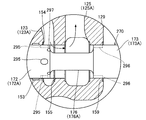
- FIG. 2 is a cross-sectional view showing the travel control valve unit of the valve device according to the first embodiment of the present invention, showing a state where the main spool is at a neutral position.
- FIG. 3 is a cross-sectional view showing a travel control valve unit of the valve device according to the first embodiment of the present invention, in which the main spool is at a position at an initial stage of movement, and a second notch as a discharge unit (bleed-off throttle). Shows a state in which a part of hydraulic oil is discharged from the tank to the tank.
- FIG. 1 is a hydraulic circuit diagram showing a configuration of the valve device according to the first embodiment of the present invention.
- FIG. 2 is a cross-sectional view showing the travel control valve unit of the valve device according to the first embodiment of the present invention, showing a state where the main spool is at a neutral position.
- FIG. 3
- FIG. 4 is a cross-sectional view showing the travel control valve unit of the valve device according to the first embodiment of the present invention, in which the main spool is at a position at the final stage of movement, and is meter-in via a first notch as a communication portion. This shows a state in which the outlet passage downstream of the throttle communicates with the traveling communication passage.
- FIG. 5A is an enlarged cross-sectional view showing a part of a travel control valve unit of a valve device according to a second embodiment of the present invention, in a state where a main spool is at a neutral position.
- FIG. 5B is an enlarged cross-sectional view showing a part of the travel control valve unit of the valve device according to the second embodiment of the present invention in an enlarged manner, and shows a state where the main spool has moved a predetermined distance X1 from the neutral position.
- FIG. 6A is an enlarged cross-sectional view showing a part of a travel control valve unit of a valve device according to a second embodiment of the present invention, and shows a state where a main spool has moved a predetermined distance X2 from a neutral position.
- FIG. 6B is an enlarged sectional view showing a part of the travel control valve unit of the valve device according to the second embodiment of the present invention in an enlarged manner, and shows a state where the main spool has moved from the neutral position by a predetermined distance X3.
- FIG. 7 is an enlarged cross-sectional view showing a part of a travel control valve unit of a valve device according to a modification of the second embodiment of the present invention. Show.
- valve device is mounted on a working machine, such as a construction machine, an agricultural machine, or an industrial machine, provided with a traveling device.
- a valve device mounted on a crawler-type hydraulic excavator as a working machine will be described as an example.
- hydraulic fluid is used as a working fluid for driving an actuator of a work machine.
- another fluid such as working water may be used as the working fluid.
- the hydraulic shovel includes a traveling unit, a turning unit provided to be able to turn above the traveling unit, and an excavation unit provided in the turning unit.
- the traveling unit has a pair of right and left crawlers.
- the pair of left and right crawlers is driven by left and right traveling motors, which will be described later, so that the hydraulic excavator travels.
- the excavating unit includes a boom rotatably attached to the turning unit, an arm rotatably attached to the boom, and a bucket rotatably attached to the arm.
- FIG. 1 is a hydraulic circuit diagram showing a configuration of the valve device 100.
- a hydraulic excavator includes a traveling unit, a turning unit, and a hydraulic pump driven by an engine, a pump 110 serving as a fluid pressure pump that discharges hydraulic oil, and hydraulic oil discharged from the pump 110.
- Examples of the plurality of actuators include a traveling motor 111 (a left traveling motor 111L and a right traveling motor 111R), which is a hydraulic motor for driving the traveling unit, a hydraulic motor (not shown) for driving the turning unit, and a hydraulic cylinder for driving the boom. (Not shown), a hydraulic cylinder for driving the arm (not shown), a hydraulic cylinder for driving the bucket (not shown), and the like.
- the pump 110 is a variable displacement piston pump, and the displacement of the pump 110 is changed by changing the inclination of the swash plate 110b by the regulator 110a.
- the discharge capacity of the pump 110 is set so that the differential pressure between the discharge pressure of the pump 110 guided to the regulator 110a and the maximum load pressure of each actuator (the highest load pressure among the load pressures of a plurality of actuators) becomes a predetermined value. Is controlled by so-called load sensing control.
- the valve device 100 includes a plurality of valve units, and controls the operation of each actuator by an actuator control valve incorporated in each valve unit.
- the valve device 100 will be described in detail with reference to FIG.
- the housing of the valve device 100 is formed by stacking and fastening the valve bodies of each valve unit.
- the valve body of each valve unit is formed in a rectangular parallelepiped shape.
- the valve body constituting the housing of the valve device 100 includes a valve block B which is a valve body in which each actuator control valve is incorporated, an inlet block IB which is a valve body for taking in hydraulic oil, and the like. Note that the inlet block IB is also an outlet block OB for discharging hydraulic oil to the tank 119.
- Each valve body (IB, B) is provided with a supply passage 121 to which hydraulic oil discharged from the pump 110 is supplied and a discharge passage 129 communicating with the tank 119.
- a relief valve 109 and an unload valve 108 interposed between the supply passage 121 and the discharge passage 129 are incorporated.
- the relief valve 109 regulates the maximum discharge pressure of the pump 110 and protects the hydraulic circuit.
- the unload valve 108 guides the hydraulic oil discharged from the pump 110 to the tank 119 when each actuator is not operating, and causes the pump 110 to perform a no-load operation (unload).
- Each valve block B incorporates an actuator control valve for controlling the flow of hydraulic oil supplied from the pump 110 to the actuator, and a pressure compensating valve associated with the actuator control valve.
- a travel control valve 131 (a left travel control valve 131L and a right travel control valve 131R), which is an actuator control valve for driving the travel motor 111 (a left travel motor 111L and a right travel motor 111R), and a travel control valve
- the traveling control valve unit 130 (the left traveling control valve unit 130L and the right traveling control valve unit 130R) in which the pressure compensating valve 140 associated with 131 is incorporated is illustrated.
- FIG. 1 the illustration of a valve unit in which an actuator control valve for controlling an actuator such as a boom, an arm, and a bucket is incorporated is simplified or omitted.
- Each actuator control valve is switched by a pilot pressure output in response to operation of an operation lever (not shown).
- the hydraulic system of the present embodiment employs an after-orifice type load sensing system in which a pressure compensating valve 140 is provided downstream of the meter-in throttle 134 of each actuator control valve.
- a pressure compensating valve 140 is provided downstream of the meter-in throttle 134 of each actuator control valve.
- the pressure compensating valve 140 functions as a load adjustment between the actuators.
- the pressure compensating valve 140 is provided with the pressure downstream of the meter-in throttle 134 provided in the actuator control valve and the maximum load pressure of each actuator (the highest load pressure among the load pressures of a plurality of actuators). You.
- the pressure compensating valve 140 compensates for the pressure downstream of the meter-in throttle 134 to be higher than the maximum load pressure of each actuator by a predetermined value. Therefore, in the hydraulic system according to the present embodiment, when simultaneously driving a plurality of actuator control valves, regardless of the magnitude of the load pressure of the actuator, hydraulic fluid is supplied at a flow rate corresponding to the operation amount of the spool of the actuator control valve. be able to.
- a left travel control valve 131L that controls the flow of hydraulic oil supplied from the pump 110 to the left travel motor 111L is incorporated in the valve block B1.
- a left traveling control valve unit 130L having the valve block B1 and the left traveling control valve 131L is configured.
- the left traveling motor 111L is a hydraulic motor that drives a crawler (not shown) on the left side of the hydraulic shovel.
- a right travel control valve 131R that controls the flow of hydraulic oil supplied from the pump 110 to the right travel motor 111R is incorporated in the valve block B2 adjacent to the valve block B1.
- a right traveling control valve unit 130R including the valve block B2 and the right traveling control valve 131R is configured.
- the right running motor 111R is a hydraulic motor that drives a right crawler (not shown) of the hydraulic shovel.
- the left traveling control valve unit 130L and the right traveling control valve unit 130R are arranged adjacent to each other, and are stacked together with the other valve units, thereby configuring the valve device 100. .
- the left traveling control valve unit 130L and the right traveling control valve unit 130R have the same configuration, and have a substantially plane-symmetric shape with respect to their contact surfaces.
- the travel control valve 131 rotates the travel motor 111 to the neutral position (N) for stopping the travel motor 111, the forward position (F) which is an operating position for rotating the travel motor 111 to one side, and the other.
- the pilot-operated directional control valve is switched between a retracted position (R), which is an operating position for the pilot valve.
- FIG. 2 is a cross-sectional view showing the travel control valve unit 130 of the valve device 100, and shows a state where the main spool 170 is at a neutral position (N).
- Each of the left and right travel control valve units 130L, 130R is a main in which a meter-in throttle 134 (see FIG. 1) provided between the pump 110 and the travel motor 111 and a spool that moves in the axial direction based on a travel operation command. It has a spool 170, a compensator spool 180 that moves in a direction perpendicular to the axial direction of the main spool 170, and a valve block B that houses the main spool 170 and the compensator spool 180.
- the valve block B is provided with a main housing hole 150 for slidably housing the main spool 170 and a sub housing hole 160 for slidably housing the compensator spool 180.
- the traveling operation command is a pilot pressure output from a pilot pressure output unit (not shown) to a first pilot pressure chamber 135a or a second pilot pressure chamber 135b, which will be described later, according to the operation amount of a traveling operation lever (not shown).
- valve block B and the main spool 170 are substantially symmetrical.
- the travel control valve 131 includes a main spool 170, a first pilot pressure chamber 135 a and a second pilot pressure chamber 135 b for controlling driving of the main spool 170, and a centering spring for urging the main spool 170 toward the axial center thereof. 137.
- the main spool 170 has a centering spring when the first pilot pressure chamber 135a and the second pilot pressure chamber 135b are connected to the tank 119 and no pilot pressure is applied to the first pilot pressure chamber 135a and the second pilot pressure chamber 135b. It is held at the neutral position (N) by the urging force of 137.
- the main spool 170 is switched to the forward position (F)
- the pilot pressure acts on the second pilot pressure chamber 135b
- the main spool 170 is switched to the retreat position (R).
- the valve block B has a supply passage 121 (see FIG. 1) through which hydraulic oil discharged from the pump 110 is supplied, a pair of supply branch passages 121 a and 121 b branched from the supply passage 121, and a downstream side of the meter-in throttle 134. And a pair of lead-out passages 123 (a first lead-out passage 123A and a second lead-out passage 123B) that constitute a passage on the upstream side of the pressure compensation valve 140 and a passage on the downstream side of the pressure compensation valve 140. And a first traveling communication passage 124A (see FIGS.
- a second traveling communication passage 124B (which communicates the second outlet passage 123B of the valve unit 130L with the second outlet passage 123B of the right traveling control valve unit 130R). 1), a pair of actuator passages 125 (first actuator passage 125A and second actuator passage 125B) communicating with the travel motor 111, a discharge passage 129 communicating with the tank 119, and a plurality of valves controlled by the valve device 100. And a load pressure passage 128 (see FIG. 1) through which the highest load pressure among the actuators is guided.
- the pair of lead-out passages 123 constitutes a so-called bridge passage having a bridge shape.
- the pair of lead-out passages 123 are provided on the downstream side of the meter-in throttle 134 and guide the hydraulic oil supplied from the supply passage 121 to the actuator passage 125.
- the traveling communication passage 124 (the first traveling communication passage 124A and the second traveling communication passage 124B) shown in FIGS. 1 and 4 is provided between the outlet passages 123 of the left and right traveling control valve units 130L and 130R (the first outlet passages 123A are connected to each other). And the second outlet passage 123B), and is provided to make the flow rates of the hydraulic oil supplied to the left and right traveling motors 111 equal.
- the traveling communication passage 124 extends in the width direction of the valve block B (the direction perpendicular to the plane of FIG. 4).
- a throttle 124c is provided in the traveling communication passage 124 of the right traveling control valve unit 130R to provide resistance to the passing hydraulic oil.
- the throttle 124c may be provided in the traveling communication passage 124 of the left traveling control valve unit 130L, or in both the traveling communication passage 124 of the left traveling control valve unit 130L and the traveling communication passage 124 of the right traveling control valve unit 130R. It may be provided.
- a plurality of annular concave portions 151, 152, 153, 154, 155 connected to the passages 122, 121 a, 121 b, 124, 123, 125, 129 are formed on the inner peripheral surface of the main housing hole 150. , 159 are provided.
- the introduction passage 122 is connected to the annular recess 151 provided at the axial center of the main housing hole 150 and the sub housing hole 160.
- the pair of supply branch passages 121a and 121b are connected to a pair of annular recesses 152 provided so as to sandwich the annular recess 151.
- the pair of traveling communication passages 124 is connected to a pair of annular recesses 153 provided so as to sandwich the pair of annular recesses 152.
- the pair of outlet passages 123 is connected to a pair of annular recesses 154 provided so as to sandwich the pair of annular recesses 153.
- the pair of actuator passages 125 are connected to a pair of annular recesses 155 provided so as to sandwich the pair of annular recesses 154.
- the discharge passage 129 is connected to a pair of annular recesses 159 provided so as to sandwich the pair of annular recesses 155.
- the pair of actuator passages 125 (the first actuator passage 125A and the second actuator passage 125B) form a pair of actuator ports 126 (the first actuator port 126A and the second actuator port 126B) opening on the outer peripheral surface of the valve block B.
- the annular recess 155 is connected.
- a compensator spool 180 is interposed between the pair of outlet passages 123 forming the bridge passage.
- An annular recess 161 connected to the pair of lead-out passages 123 is provided on the inner peripheral surface of the sub housing hole 160. That is, the outlet passage 123 has one end communicating with the main housing hole 150 and the other end communicating with the sub housing hole 160.
- the main spool 170 has a plurality of columnar lands that are in sliding contact with the inner peripheral surface of the main housing hole 150.
- a first supply-side land 171A and a second supply-side land 171B which are a pair of supply-side lands 171 provided at the axial center of the main spool 170, and a pair of supply-side lands.
- a first lead-out land portion 172A and a second lead-out land portion 172B that are a pair of lead-out land portions 172 provided so as to sandwich the portion 171 and a pair of discharge-side lands provided so as to sandwich the pair of lead-out land portions 172.
- Each land portion is configured such that a first discharge side land portion 173A, a first outlet side land portion 172A, a first supply side land portion 171A, The second supply land 171B, the second outlet land 172B, and the second discharge land 173B are provided in this order.
- the supply-side land portion 171 is a land portion that connects or blocks the supply passage 121 and the introduction passage 122.
- the pair of supply-side land portions 171 are configured to be able to block the pair of supply branch passages 121a and 121b by their outer peripheral surfaces.
- the lead-out side land portion 172 is a land portion that connects or disconnects the lead-out passage 123 and the actuator passage 125, and a land portion that connects or disconnects the lead-out passage 123 and the traveling communication passage 124.
- the pair of lead-out land portions 172 are configured to be able to block the pair of lead-out passages 123 by their outer peripheral surfaces.
- the discharge-side land portion 173 is a land portion that connects or blocks the actuator passage 125 and the discharge passage 129.
- the pair of discharge-side lands 173 is configured so that the discharge passage 129 can be shut off by the outer peripheral surfaces thereof.
- a first annular groove 176A is provided between the first outlet side land portion 172A and the first discharge side land portion 173A.
- a second annular groove 176B is provided between the second lead-out land 172B and the second discharge-side land 173B.
- the first annular groove 176A and the second annular groove 176B are also collectively referred to as an annular groove 176.
- a central annular groove 175 is provided between the first supply side land 171A and the second supply side land 171B.
- the central annular groove 175 is provided so as to face the introduction passage 122 and always communicates with the introduction passage 122.
- the first annular groove 176A is provided to face the first actuator passage 125A, and always communicates with the first actuator passage 125A.
- the second annular groove 176B is provided so as to face the second actuator passage 125B, and always communicates with the second actuator passage 125B.
- a plurality of first central notches 191A are provided on the first supply side land portion 171A so as to be spaced apart in the circumferential direction.
- the first central notch 191A extends in the axial direction of the main spool 170, and opens to the outer peripheral surface and the central annular groove 175 of the first supply-side land portion 171A.
- a plurality of second central notches 191B are provided in the second supply side land portion 171B so as to be spaced apart in the circumferential direction.
- the second central notch 191B extends in the axial direction of the main spool 170, and opens to the outer peripheral surface and the central annular groove 175 of the second supply-side land 171B.
- a plurality of first notches 192A are provided on the first outlet side land portion 172A so as to be spaced apart in the circumferential direction.
- the first notch 192A extends in the axial direction of the main spool 170, and opens to the outer peripheral surface of the first outlet side land portion 172A and the first annular groove 176A.
- a plurality of second notches 192B are provided in the second outlet side land portion 172B so as to be spaced apart in the circumferential direction.
- the second notch 192B extends in the axial direction of the main spool 170, and opens to the outer peripheral surface of the second outlet side land portion 172B and the second annular groove 176B.
- the compensator spool 180 is arranged so that one end (the lower end in the figure) faces the introduction passage 122 and the other end (the upper end in the figure) faces the maximum load pressure chamber 185.
- the maximum load pressure chamber 185 is a pressure chamber that communicates with the load pressure passage 128 (see FIG. 1) and into which the maximum load pressure of each actuator is led.
- the compensator spool 180 is provided with a throttle portion 181 that imparts resistance to the passing hydraulic oil at an initial stage when the compensator spool 180 moves to the maximum load pressure chamber 185 side.
- the degree of opening of the throttle portion 181 relative to the annular concave portion 161 increases as the compensator spool 180 moves toward the maximum load pressure chamber 185.
- the compensator spool 180 is provided with a pressure introducing portion 182 whose opening degree with respect to the annular concave portion 161 is variable according to the moving position.
- a groove is formed around the opening of the pressure introducing portion 182 on the side of the annular recess 161, and in the process of moving the groove relative to the annular recess 161, the substantial opening degree of the pressure introducing portion 182 with respect to the annular recess 161 is increased.
- the high-pressure selection valve 183 is incorporated in the compensator spool 180.
- the high-pressure selection valve 183 is arranged such that one end (the lower end in the drawing) faces the pressure introducing chamber 184 communicating with the pressure introducing portion 182, and the other end (the upper end in the drawing) faces the maximum load pressure chamber 185.
- the high-pressure selection valve 183 maintains the closed state when the pressure in the maximum load pressure chamber 185, that is, the maximum load pressure of each actuator is higher than the pressure in the pressure introduction chamber 184.
- the high-pressure selection valve 183 opens when the pressure in the pressure introduction chamber 184 is higher than the pressure in the maximum load pressure chamber 185, and guides the pressure in the pressure introduction chamber 184 to the load pressure passage 128 (see FIG. 1).
- FIGS. 3 and 4 are cross-sectional views showing the travel control valve unit 130 of the valve device 100, similarly to FIG.
- FIG. 3 shows a state in which the main spool 170 is at a position at the initial stage of movement, and a part of the hydraulic oil is discharged to the tank 119 from the second notch 192B serving as a discharge portion (bleed-off throttle).
- FIG. 4 shows a state in which the main spool 170 is located at the final stage of movement, and the outlet passage 123 downstream of the meter-in throttle 134 communicates with the traveling communication passage 124 via the first notch 192A as a communication portion. Is shown.
- a pilot pressure as a traveling operation command acts on the first pilot pressure chamber 135a or the second pilot pressure chamber 135b of the traveling control valve 131. I do.
- the operator Inclines the left traveling operation lever to the forward side and the right traveling operation lever to the forward side.
- the operation of the valve device 100 when the left and right traveling operation levers (not shown) are simultaneously operated to the forward side to make the hydraulic shovel (vehicle) travel straight the operation of the main spool 170 and the compensator spool 180, and The flow of the hydraulic oil in the travel control valve unit 130 will be described in detail.
- the first actuator passage 125A and the discharge passage 129 communicate with each other via the first annular groove 176A, and the second actuator passage 125B and the discharge passage 129 communicate with the second actuator passage 125B. It communicates via the annular groove 176B.
- the first actuator passage 125A and the second actuator passage 125B are formed by a first annular groove 176A, a first notch 192A, and a pair of outlet passages 123 forming a bridge passage.
- the second notch 192B and the second annular groove 176B are formed by a first annular groove 176A, a first notch 192A, and a pair of outlet passages 123 forming a bridge passage.
- a pilot pressure acts on the first pilot pressure chamber 135a, and the main spool 170 starts moving in the axial direction from the neutral position (N) to one side (left side in the figure). I do.
- the supply branch passage 121b and the introduction passage 122 communicate with each other through the second central notch 191B.
- the communication opening at this time constitutes the meter-in stop 134 shown in FIG.
- the pressure of the hydraulic oil guided to the introduction passage 122 becomes lower than the pump discharge pressure by a pressure loss corresponding to the opening of the meter-in throttle 134.
- the hydraulic oil guided to the first actuator passage 125A is supplied to the traveling motor 111 through the first actuator port 126A, and the traveling motor 111 rotates.
- the operating oil discharged from the traveling motor 111 is guided to the second actuator passage 125B through the second actuator port 126B.
- the hydraulic oil guided to the second actuator passage 125B is guided to the discharge passage 129 through the second annular groove 176B, and is discharged to the tank 119.
- the supply passage 121 passes through the introduction passage 122 through the introduction passage 123. Is supplied to the first actuator passage 125A through the first annular groove 176A, and the traveling motor 111 rotates.
- the second outlet passage 123B communicates with the second annular groove 176B via the second notch 192B. For this reason, as indicated by the dashed arrow in the drawing, part of the hydraulic oil guided from the supply passage 121 to the outlet passage 123 through the introduction passage 122 is transferred to the discharge passage 129 through the second notch 192B and the second annular groove 176B. Is discharged.
- the main spool 170 of the traveling control valve unit 130 moves in response to the traveling operation command, a part of the hydraulic oil supplied from the supply passage 121 is discharged to the discharge section at an initial stage of the movement. It is discharged from the second notch 192B functioning as (bleed-off stop). Therefore, immediately after the start of the operation of the travel operation lever, the hydraulic oil is prevented from flowing abruptly to the travel motor 111, and the start of the travel motor 111 in response to the travel operation command can be made smooth. That is, according to the present embodiment, it is possible to prevent the vehicle body from shaking or shock at the start of traveling, and to improve the traveling performance at the start of traveling.
- the movement of the main spool 170 is reversed from the above-described movement, and the first notch 192A shown in FIG. 2 functions as a discharge unit (bleed-off aperture). That is, when the main spool 170 moves from the neutral position (N) to the other side in the axial direction, at the initial stage of the movement, the hydraulic oil guided from the supply passage 121 to the outlet passage 123 passes through the second annular groove 176B and the second actuator passage 125B. And a part of the hydraulic oil guided from the supply passage 121 to the outlet passage 123 is discharged to the discharge passage 129 through the first notch 192A as a discharge part. Therefore, even when the vehicle is moving backward, the start of the traveling motor 111 in response to the traveling operation command can be made smooth, and the traveling performance at the start of traveling can be improved.
- the traveling communication path 124 when the traveling communication path 124 is not provided, if there is a processing error in the left and right traveling control valves 131L, 131R, the pressure compensating valve 140, etc., the hydraulic oil supplied to the left and right traveling motors 111L, 111R is biased. Is generated, and there is a possibility that the traveling may bend.
- the first notch 192A as a communication portion provided in the lead-out land portion 172 is provided.
- the outlet passage 123 and the traveling communication passage 124 communicate with each other via the. Therefore, the flow rate to one of the left and right travel motors 111L and 111R is larger than the flow rate to the other due to the processing error in the left and right travel control valves 131L and 131R, the pressure compensation valve 140, and the like.
- part of the hydraulic oil is guided from one circuit of the left and right traveling motors 111L and 111R to the other circuit through the traveling communication path 124. Thereby, the flow rate of the hydraulic oil is adjusted such that the flow rates of the hydraulic oil supplied to the left and right traveling motors 111L and 111R are the same.
- the main spool 170 of the left and right traveling control valve units 130L and 130R moves, the main spool 170 is moved.
- the lead-out passages 123 downstream of the meter-in throttle 134 in the left and right traveling control valve units 130L and 130R communicate with each other via a first notch 192A as a communication part. For this reason, it is possible to suppress variation in the supply flow rate of the working oil to the left and right traveling motors 111L and 111R. In other words, according to the present embodiment, it is possible to prevent the traveling bending from occurring when the left and right traveling operation levers are maximally operated to the forward side, and to improve traveling performance during straight traveling.
- the movement of the main spool 170 is reversed from the above-described movement, and the second notch 192B shown in FIG. 2 functions as a communication part. That is, when the main spool 170 moves from the neutral position (N) to the other side in the axial direction, at the final stage of the movement, the lead-out passage 123 and the traveling communication passage 124 communicate with each other through the second notch 192B as a communication portion.
- the outlet passages 123 in the left and right traveling control valve units 130L and 130R communicate with each other. For this reason, even when the vehicle retreats, the straight traveling performance can be improved.
- the main spool 170 moves from the neutral position (N) to one side, at the final stage of the movement, the main spool 170 is provided with a communication portion that communicates the lead-out passage 123 with the traveling communication passage 124.
- the first notch 192A functions as a communication part
- the second notch 192B functions as a communication part.
- the second notch 192B functions as a discharge unit at the initial stage of movement
- the first notch 192A functions as a communication unit at the final stage of movement.
- the first notch 192A functions as a discharge unit in an initial stage of movement
- the second notch 192B functions as a communication unit in a final stage of movement.
- one type of notch 192A, 192B provided on the outlet side land portion 172 functions as a communication portion that connects the outlet passage 123 and the traveling communication passage 124, and also connects the outlet passage 123 and the discharge passage 129. It also has a function as a discharge unit (bleed-off aperture).
- FIGS. 5A, 5B, 6A, and 6B A valve device according to a second embodiment of the present invention will be described with reference to FIGS. 5A, 5B, 6A, and 6B.
- description will be made focusing on points different from the first embodiment, and in the drawings, the same or corresponding components as those described in the first embodiment will be denoted by the same reference numerals and description thereof will be omitted.
- . 5A to 6B are enlarged sectional views showing a part of the travel control valve unit in an enlarged manner.
- FIG. 5A shows a state where the main spool 270 is at the neutral position (N)
- FIG. 5B shows a state where the main spool 270 has moved a predetermined distance X1 from the neutral position (N).
- FIG. 6A shows a state where the main spool 270 has moved a predetermined distance X2 from the neutral position (N)
- FIG. 6B shows a state where the main spool 270 has moved a predetermined distance X3 from the neutral position (N).
- one type of notch 192A, 192B provided in the outlet side land portion 172 functions as a communication portion that connects the outlet passage 123 and the traveling communication passage 124, and the outlet passage 123 and the discharge passage 129. It also has a function as a discharge section (bleed-off aperture) that communicates with.
- the notch 295 provided in the discharge-side land portion 173 has the concave portion 295 provided in the discharge-side land portion 172 serving as a communication portion that connects the discharge passage 123 and the traveling communication passage 124.
- 296 functions as a discharge unit (bleed-off restriction) that connects the discharge passage 123 and the discharge passage 129. The details will be described below.
- the main spool 270 is provided with an annular groove 176 between the lead-out land portion 172 and the discharge-side land portion 173 as in the first embodiment.
- the notch 296 as a discharge portion (bleed-off stop) is provided in the discharge-side land portion 173 so as to be spaced apart in the circumferential direction.
- Notch 296 is provided to extend in the axial direction of main spool 270.
- the notch 296 is provided on the discharge side land portion 173 so as to open to the outer peripheral surface and the annular groove 176.
- the concave portion 295 as the communication portion is provided in the lead-out side land portion 172 so as to be spaced apart in the circumferential direction.
- the concave portion 295 is provided in the outlet side land portion 172 so as to open on the outer peripheral surface thereof and not to open in the annular groove 176.
- the concave portion 295 is formed in a racing track shape in which both ends of two sides parallel to the axial direction of the main spool 270 are connected by an arc.
- a plurality of notches 297 are provided on the lead-out side land portion 172 so as to be spaced apart in the circumferential direction.
- the notch 297 extends in the axial direction of the main spool 270 and opens in the outer peripheral surface of the outlet side land portion 172 and the annular groove 176.
- the main spool 270 is held at the neutral position (N).
- the communication between the supply passage 121 and the introduction passage 122 is interrupted by the supply land portion 171 as in the first embodiment (see FIG. 2).
- the actuator passage 125 and the discharge passage 129 communicate with each other via the annular groove 176.
- the supply branch passage 121b and the introduction passage 122 are connected to the second passage as in the first embodiment. They communicate via a central notch 191B (see FIG. 3).
- the first annular groove 176A communicates with the discharge passage 129 via the notch 296. For this reason, as shown by the dashed arrow in FIG. 5B, a part of the hydraulic oil guided from the supply passage 121 to the outlet passage 123 through the introduction passage 122 is discharged to the discharge passage 129 through the first annular groove 176A and the notch 296. You.
- the first derivation is performed as shown in FIG. 6B.
- the passage 123A and the first traveling communication passage 124A communicate with each other via a concave portion 295 provided in the first outlet side land portion 172A.
- the first travel communication path 124A of the left travel control valve unit 130L and the first travel communication path 124A of the right travel control valve unit 130R communicate. I do.
- the lead-out passage 123 and the traveling communication passage are provided via the concave portion 295 as a communication portion provided in the lead-out land portion 172. And 124. Therefore, when there is a processing error in the left and right travel control valves 131L, 131R, the pressure compensating valve 140, and the like, the flow rate of the hydraulic oil supplied to the left and right travel motors 111L, 111R is the same. Is adjusted.
- the concave portion 295 is provided in the outlet side land portion 172 as a communication portion that connects the outlet passage 123 and the traveling communication passage 124. Therefore, by adjusting the axial length of the concave portion 295, the timing at which the outlet passages 123 of the left and right traveling control valve units 130 communicate with each other can be set more appropriately.
- the discharge side land portion 173 is provided with a notch 296 as a discharge portion (bleed-off restriction) that connects the discharge passage 123 and the discharge passage 129.
- a notch 296 as a discharge portion (bleed-off restriction) that connects the discharge passage 123 and the discharge passage 129.
- the timing for closing the opening of the bleed-off aperture and the timing for starting the communication between the lead-out passage 123 and the traveling communication passage 124 can be individually set, so that the traveling performance of the vehicle is improved.
- the degree of freedom of adjustment is high.
- the notch 297 provided on the outlet side land portion 172 can control the timing at which the outlet passage 123 and the actuator passage 125 communicate with each other. Therefore, by adjusting the axial length of the notch 297, the start timing of the traveling motor 111 can be set more appropriately.
- the discharge portion provided in the discharge side land portion 173 is not limited to the notch 296 described in the second embodiment.
- the discharge unit may be configured by a plurality of passages.
- the discharge portion 396 communicating the discharge passage 123 and the discharge passage 129 has a first discharge passage 396a communicating with the annular groove 176, and a second discharge passage 396a communicating with the first discharge passage 396a and opening on the outer peripheral surface of the discharge side land portion 173. And a discharge path 396b.
- the second discharge path 396b extends in the radial direction of the main spool 370.
- the hydraulic oil discharged into the discharge passage 129 through the discharge portion 396 is radially outward from the opening end of the second discharge passage 396b, that is, in a direction orthogonal to the axial direction of the main spool 370. Is discharged.
- the hydraulic oil flows from the notch 296 toward the discharge passage 129 along the axial direction of the main spool 270 as indicated by the broken arrow in FIG. 5B. Fluid force is generated to hinder movement.
- the hydraulic oil flows from the discharge portion 396 shown in FIG. 7 toward the discharge passage 129 in a direction orthogonal to the axial direction of the main spool 270. Since the hydraulic oil is discharged in the radial direction from the second discharge path 396b of the discharge side land portion 173, it is possible to suppress the generation of the fluid force that hinders the axial movement of the main spool 370. That is, it is possible to suppress that the movement of the main spool 370 in the axial direction is hindered by the hydraulic oil flowing from the discharge portion 396 to the discharge passage 129.
- ⁇ Modification 1> In the first embodiment, a description will be given of an example in which a discharge portion (notches 192A and 192B) for controlling the bleed-off flow rate is provided in the lead-out land portion 172. Although the example provided in the unit 173 has been described, the present invention is not limited to this. A discharge unit may be provided in both the lead-out land unit 172 and the discharge-side land unit 173.
- the valve device 100 includes a left and right travel control valve unit 130 that controls the flow of the working fluid supplied from the fluid pressure pump (pump 110) to the left and right travel motors 111.
- Each of units 130 has a spool (main spool 170, 270, 370) that moves in the axial direction based on a traveling operation command, and a valve body (valve) that slidably accommodates the spool (main spool 170, 270, 370).
- valve body includes a supply passage 121 to which a working fluid discharged from a hydraulic pump (pump 110) is supplied, an actuator passage 125 communicating with the traveling motor 111, The working fluid supplied from the discharge passage 129 communicating with the tank 119 and the supply passage 121 is actuated. And a communication passage (running communication passage 124) that communicates the outflow passages 123 of the left and right traveling control valve units 130 with each other.
- the spools main spools 170, 270, and 370
- first notch 192A that communicates between the lead-out passage 123 and the communication passage (running communication passage 124).
- a second notch 192B, and a concave portion 295) are provided.
- the outlet passages 123 in the left and right traveling control valve units 130 communicate with each other through the communicating portions (the first notch 192A, the second notch 192B, the concave portion 295). Variations in the supply flow rate of the working fluid can be suppressed. This makes it possible to improve the traveling performance at the start of traveling and at the time of straight traveling.
- the improvement of the traveling performance is achieved by the discharge portions (first notch 192A, second notch 192B, notch 296, discharge portion 396) provided on the spool (main spool 170, 270, 370) and the communication portion (first notch). 192A, the second notch 192B, and the concave portion 295).
- the discharge portions first notch 192A, second notch 192B, and the concave portion 295).
- the spool (main spool 170) includes a first outlet side land portion 172 ⁇ / b> A and a second outlet side land portion 172 ⁇ / b> B as a pair of outlet side land portions 172, and a first outlet side land portion 173.
- a second annular groove 176B provided between the first discharge side land portion 173B and the first discharge side land portion 173B.
- the first outlet side land portion 172A is provided with a first notch 192A opening to the first annular groove 176A.
- the second outlet side land portion 172B is provided with a second notch 192B that opens into the second annular groove 176B, and the valve body (valve block B) is connected to the first annular groove 176.
- a second actuator passage 125B as the actuator passage 125 communicating with the second annular groove 176B.
- the spool (main spool 170) is moved from the neutral position to one end.
- the working fluid led from the supply passage 121 to the lead-out passage 123 is supplied to the first actuator passage 125A through the first annular groove 176A, and is also led from the supply passage 121 to the lead-out passage 123.
- a part of the working fluid is discharged to the discharge passage 129 through the second notch 192B as a discharge part, and when the spool (main spool 170) moves from the neutral position to one side, at the final stage of the movement, the first part as the communication part Outlet passage 12 through one notch 192A
- the working fluid guided from the supply passage 121 to the outlet passage 123 is in the initial stage of the movement when the spool (main spool 170) moves from the neutral position to the other.
- the second notch 192B functions as a discharge unit at the initial stage of movement
- the first notch 192A functions as a communication unit at the final stage of movement.
- the first notch 192A functions as a discharge unit in an initial stage of movement
- the second notch 192B functions as a communication unit in a final stage of movement. That is, by making the notches 192A and 192B formed in the outlet side land portion 172 function as the discharge portion and the communication portion, the traveling performance at the time of starting and the traveling performance at the time of going straight can be improved.
- the spools (main spools 270 and 370) have an annular groove 176 provided between the lead-out land portion 172 and the discharge-side land portion 173, and the discharge portions (notches 296 and discharge portions 396) are provided.
- the discharge side land portion 173 is provided so as to open to the outer peripheral surface thereof and the annular groove 176, and the communication portion (recess 295) opens to the outer peripheral surface thereof at the outlet side land portion 172 and opens to the annular groove 176. It is provided not to be.
- the discharge portions (notches 296 and discharge portions 396) provided on the discharge side land portion 173 supply the supply to the lead-out passage 123.
- the timing at which the discharge of a part of the fluid is stopped is controlled, and the timing at which the communication between the outlet passage 123 and the communication passage (running communication passage 124) is started by the communication portion (recess 295) provided on the outlet land portion 172. Can be controlled.
- the valve device 100 includes a first discharge path 396a in which the discharge portion 396 communicates with the annular groove 176, and a second discharge path 396b that communicates with the first discharge path 396a and opens on the outer peripheral surface of the discharge side land portion 173. And a second discharge path 396b extends in the radial direction of the spool (main spool 370).
- a notch 297 that opens into the annular groove 176 is provided in the outlet side land portion 172, and when the notch 297 moves the spool (main spool 270, 370) from the neutral position, the outlet passage 123 and the actuator passage And 125.
- the timing at which the lead-out passage 123 and the actuator passage 125 communicate with each other can be controlled by the notch 297.
Landscapes
- Engineering & Computer Science (AREA)
- General Engineering & Computer Science (AREA)
- Mechanical Engineering (AREA)
- Mining & Mineral Resources (AREA)
- Civil Engineering (AREA)
- Structural Engineering (AREA)
- Physics & Mathematics (AREA)
- Fluid Mechanics (AREA)
- Fluid-Pressure Circuits (AREA)
- Operation Control Of Excavators (AREA)
- Valve Housings (AREA)
- Sliding Valves (AREA)
- Multiple-Way Valves (AREA)
- General Physics & Mathematics (AREA)
- Automation & Control Theory (AREA)
Abstract
In a valve device (100), a travel control valve unit (130) has a communication passage for connecting the delivery passages (123) of left and right travel control valve units (130), and a spool (170) has a delivery-side land section (172) for allowing or blocking communication between the delivery passage (123) and the communication passage; a discharge-side land section (173) for allowing or blocking communication between an actuator passage (125) and a discharge passage (129); a discharge section (192B) which is provided at the delivery-side land section (172) and which, in a movement initial stage of the spool (170), discharges, to the discharge passage (129), part of operating fluid conducted from a supply passage to the delivery passage (123); and a communication section (192A) which is provided at the delivery-side land section (172) and which, in a movement final stage of the spool (170), connects the delivery passage (123) and the communication passage.
Description
本発明は、弁装置に関する。
The present invention relates to a valve device.
左右の走行モータへの作動流体の流れを制御する左右の走行制御弁を備えた油圧駆動装置が知られている(JP2006-82767A参照)。JP2006-82767Aに記載の技術では、左右の走行制御弁に作動流体を供給する供給通路同士を、2位置切換弁を介して連通させ、左右の走行モータに供給される作動流体の流量を等しくすることにより、走行蛇行の直進補正を行い、走行性の向上を図っている。
油 圧 Hydraulic drive devices having left and right travel control valves for controlling the flow of working fluid to the left and right travel motors are known (see JP2006-82767A). In the technique described in JP2006-82767A, supply passages for supplying working fluid to the left and right traveling control valves are communicated via a two-position switching valve so that the flow rates of the working fluid supplied to the left and right traveling motors are equalized. In this way, the traveling meandering is corrected in a straight line to improve the traveling performance.
近年、走行性の向上の要望だけでなく、小型化の要望が強くなっている。しかしながら、JP2006-82767Aに記載の技術では、左右の走行制御弁を連通させる2位置切換弁が必要であり、小型化が難しいという問題がある。
In recent years, there has been an increasing demand for downsizing as well as improved running performance. However, the technique described in JP2006-82767A requires a two-position switching valve for communicating the left and right traveling control valves, and has a problem that miniaturization is difficult.
本発明は、走行性を向上するとともに小型化を図ることのできる弁装置を提供することを目的とする。
An object of the present invention is to provide a valve device that can improve running performance and can be downsized.
本発明のある態様によれば、流体圧ポンプから左右の走行モータへ供給される作動流体の流れを制御する左右の走行制御弁ユニットを備えた弁装置であって、前記左右の走行制御弁ユニットのそれぞれは、走行操作指令に基づいて軸方向に移動するスプールと、前記スプールを摺動自在に収容するバルブボディと、を備え、前記バルブボディは、前記流体圧ポンプから吐出される作動流体が供給される供給通路と、前記走行モータに連通するアクチュエータ通路と、タンクに連通する排出通路と、前記供給通路から供給された作動流体を前記アクチュエータ通路に導く導出通路と、前記左右の走行制御弁ユニットの前記導出通路同士を連通する連通路と、を有し、前記スプールは、前記導出通路と前記連通路とを連通または遮断するランド部であって、その外周面により前記導出通路を遮断可能な導出側ランド部と、前記アクチュエータ通路と前記排出通路とを連通または遮断するランド部であって、その外周面により前記排出通路を遮断可能な排出側ランド部と、前記導出側ランド部及び前記排出側ランド部の少なくとも一方に設けられ、前記スプールが中立位置から一方に移動する際、その移動初期段階において、前記供給通路から前記導出通路に導かれる作動流体の一部を前記排出通路に排出する排出部と、前記導出側ランド部に設けられ、前記スプールが中立位置から一方に移動する際、その移動最終段階において、前記導出通路と前記連通路とを連通する連通部と、を有する。
According to an aspect of the present invention, there is provided a valve device including left and right travel control valve units for controlling a flow of a working fluid supplied from a fluid pressure pump to left and right travel motors, wherein the left and right travel control valve units are provided. Each includes a spool that moves in the axial direction based on a traveling operation command, and a valve body that slidably accommodates the spool.The valve body receives a working fluid discharged from the fluid pressure pump. A supply passage that is supplied, an actuator passage that communicates with the travel motor, a discharge passage that communicates with the tank, an outlet passage that guides the working fluid supplied from the supply passage to the actuator passage, and the left and right travel control valves. A communication passage for communicating the outlet passages of the unit with each other, wherein the spool communicates with or blocks the outlet passage and the communication passage. A land portion that allows the discharge passage to be blocked by the outer peripheral surface thereof; and a land portion that communicates or blocks the discharge passage with the actuator passage. The discharge passage can be blocked by the outer peripheral surface. A discharge side land portion, and at least one of the discharge side land portion and the discharge side land portion, when the spool moves from the neutral position to one side, in the initial stage of the movement, the supply passage extends from the supply passage to the discharge passage. A discharge portion that discharges a part of the working fluid guided to the discharge passage, provided on the discharge side land portion, when the spool moves from the neutral position to one side, at the final stage of the movement, the discharge passage and And a communication part that communicates with the communication passage.
図面を参照して、本発明の実施形態に係る弁装置について説明する。弁装置は、走行装置を備えた建設機械、農業機械、産業機械等の作業機械に搭載される。以下では、作業機械としてのクローラ式の油圧ショベルに搭載される弁装置を一例に説明する。また、作業機械のアクチュエータの駆動には、作動流体として作動油を用いる例について説明するが、作動流体には作動水等の他の流体を用いてもよい。
弁 A valve device according to an embodiment of the present invention will be described with reference to the drawings. The valve device is mounted on a working machine, such as a construction machine, an agricultural machine, or an industrial machine, provided with a traveling device. Hereinafter, a valve device mounted on a crawler-type hydraulic excavator as a working machine will be described as an example. Further, an example in which hydraulic fluid is used as a working fluid for driving an actuator of a work machine will be described. However, another fluid such as working water may be used as the working fluid.
図示しないが、油圧ショベルは、走行部と、走行部の上部に旋回可能に設けられる旋回部と、旋回部に設けられる掘削部と、を備える。走行部は、左右一対のクローラを有する。左右一対のクローラが、後述する左右の走行モータによって駆動されることにより、油圧ショベルが走行する。掘削部は、旋回部に回動可能に取り付けられるブームと、ブームに回動可能に取り付けられるアームと、アームに回動可能に取り付けられるバケットと、を備える。
し な い Although not shown, the hydraulic shovel includes a traveling unit, a turning unit provided to be able to turn above the traveling unit, and an excavation unit provided in the turning unit. The traveling unit has a pair of right and left crawlers. The pair of left and right crawlers is driven by left and right traveling motors, which will be described later, so that the hydraulic excavator travels. The excavating unit includes a boom rotatably attached to the turning unit, an arm rotatably attached to the boom, and a bucket rotatably attached to the arm.
<第1実施形態>
図1は、弁装置100の構成を示す油圧回路図である。図1に示すように、油圧ショベルは、エンジン(不図示)と、エンジンにより駆動され作動油を吐出する流体圧ポンプとしてのポンプ110と、ポンプ110から吐出される作動油によって、走行部、旋回部、掘削部等を駆動するための複数のアクチュエータを制御する弁装置100と、弁装置100から作動油が還流するタンク119と、を備える。 <First embodiment>
FIG. 1 is a hydraulic circuit diagram showing a configuration of thevalve device 100. As shown in FIG. 1, a hydraulic excavator includes a traveling unit, a turning unit, and a hydraulic pump driven by an engine, a pump 110 serving as a fluid pressure pump that discharges hydraulic oil, and hydraulic oil discharged from the pump 110. A valve device 100 for controlling a plurality of actuators for driving a section, a digging section, and the like, and a tank 119 in which hydraulic oil flows from the valve device 100.
図1は、弁装置100の構成を示す油圧回路図である。図1に示すように、油圧ショベルは、エンジン(不図示)と、エンジンにより駆動され作動油を吐出する流体圧ポンプとしてのポンプ110と、ポンプ110から吐出される作動油によって、走行部、旋回部、掘削部等を駆動するための複数のアクチュエータを制御する弁装置100と、弁装置100から作動油が還流するタンク119と、を備える。 <First embodiment>
FIG. 1 is a hydraulic circuit diagram showing a configuration of the
複数のアクチュエータとしては、例えば、走行部駆動用の油圧モータである走行モータ111(左走行モータ111L及び右走行モータ111R)、旋回部駆動用の油圧モータ(不図示)、ブーム駆動用の油圧シリンダ(不図示)、アーム駆動用の油圧シリンダ(不図示)、バケット駆動用の油圧シリンダ(不図示)等がある。
Examples of the plurality of actuators include a traveling motor 111 (a left traveling motor 111L and a right traveling motor 111R), which is a hydraulic motor for driving the traveling unit, a hydraulic motor (not shown) for driving the turning unit, and a hydraulic cylinder for driving the boom. (Not shown), a hydraulic cylinder for driving the arm (not shown), a hydraulic cylinder for driving the bucket (not shown), and the like.
ポンプ110は、可変容量型のピストンポンプであり、レギュレータ110aにより斜板110bの傾きが変更されることで吐出容量が変化する。ポンプ110の吐出容量は、レギュレータ110aに導かれるポンプ110の吐出圧と各アクチュエータの最高負荷圧(複数のアクチュエータの負荷圧のうちで最も高い負荷圧)との差圧が所定の値となるように、いわゆるロードセンシング制御によって制御される。
The pump 110 is a variable displacement piston pump, and the displacement of the pump 110 is changed by changing the inclination of the swash plate 110b by the regulator 110a. The discharge capacity of the pump 110 is set so that the differential pressure between the discharge pressure of the pump 110 guided to the regulator 110a and the maximum load pressure of each actuator (the highest load pressure among the load pressures of a plurality of actuators) becomes a predetermined value. Is controlled by so-called load sensing control.
弁装置100は、複数の弁ユニットを備え、各弁ユニットに組み込まれるアクチュエータ制御弁によって、各アクチュエータの動作を制御する。図1を参照して、弁装置100について詳しく説明する。弁装置100のハウジングは、各弁ユニットのバルブボディを積層し、締結することにより形成される。各弁ユニットのバルブボディは、直方体形状に形成される。
The valve device 100 includes a plurality of valve units, and controls the operation of each actuator by an actuator control valve incorporated in each valve unit. The valve device 100 will be described in detail with reference to FIG. The housing of the valve device 100 is formed by stacking and fastening the valve bodies of each valve unit. The valve body of each valve unit is formed in a rectangular parallelepiped shape.
弁装置100のハウジングを構成するバルブボディとしては、各アクチュエータ制御弁が組み込まれるバルブボディであるバルブブロックB、及び、作動油を取り入れるためのバルブボディであるインレットブロックIB等がある。なお、インレットブロックIBは、作動油をタンク119に排出するためのアウトレットブロックOBでもある。
The valve body constituting the housing of the valve device 100 includes a valve block B which is a valve body in which each actuator control valve is incorporated, an inlet block IB which is a valve body for taking in hydraulic oil, and the like. Note that the inlet block IB is also an outlet block OB for discharging hydraulic oil to the tank 119.
各バルブボディ(IB,B)には、ポンプ110から吐出される作動油が供給される供給通路121と、タンク119に連通する排出通路129と、が設けられる。インレットブロックIBには、供給通路121と排出通路129との間に介装されるリリーフ弁109と、アンロード弁108と、が組み込まれる。リリーフ弁109は、ポンプ110の吐出圧の最高圧力を規定し、油圧回路を保護する。アンロード弁108は、各アクチュエータが動作していないときに、ポンプ110から吐出される作動油をタンク119へ導き、ポンプ110を無負荷運転(アンロード)させる。
供給 Each valve body (IB, B) is provided with a supply passage 121 to which hydraulic oil discharged from the pump 110 is supplied and a discharge passage 129 communicating with the tank 119. In the inlet block IB, a relief valve 109 and an unload valve 108 interposed between the supply passage 121 and the discharge passage 129 are incorporated. The relief valve 109 regulates the maximum discharge pressure of the pump 110 and protects the hydraulic circuit. The unload valve 108 guides the hydraulic oil discharged from the pump 110 to the tank 119 when each actuator is not operating, and causes the pump 110 to perform a no-load operation (unload).
各バルブブロックBには、ポンプ110からアクチュエータに供給される作動油の流れを制御するアクチュエータ制御弁と、アクチュエータ制御弁に対応付けられた圧力補償弁と、が組み込まれる。なお、図1では、走行モータ111(左走行モータ111L及び右走行モータ111R)を駆動するアクチュエータ制御弁である走行制御弁131(左走行制御弁131L及び右走行制御弁131R)と、走行制御弁131に対応付けられた圧力補償弁140と、が組み込まれた走行制御弁ユニット130(左走行制御弁ユニット130L及び右走行制御弁ユニット130R)について図示している。一方、図1では、ブーム、アーム、バケット等のアクチュエータを制御するアクチュエータ制御弁が組み込まれた弁ユニットについては、その図示を簡略化または省略している。
Each valve block B incorporates an actuator control valve for controlling the flow of hydraulic oil supplied from the pump 110 to the actuator, and a pressure compensating valve associated with the actuator control valve. In FIG. 1, a travel control valve 131 (a left travel control valve 131L and a right travel control valve 131R), which is an actuator control valve for driving the travel motor 111 (a left travel motor 111L and a right travel motor 111R), and a travel control valve The traveling control valve unit 130 (the left traveling control valve unit 130L and the right traveling control valve unit 130R) in which the pressure compensating valve 140 associated with 131 is incorporated is illustrated. On the other hand, in FIG. 1, the illustration of a valve unit in which an actuator control valve for controlling an actuator such as a boom, an arm, and a bucket is incorporated is simplified or omitted.
各アクチュエータ制御弁は、操作レバー(不図示)の操作に応じて出力されるパイロット圧により切り換えられる。
ア ク チ ュ エ ー タ Each actuator control valve is switched by a pilot pressure output in response to operation of an operation lever (not shown).
本実施形態の油圧システムでは、各アクチュエータ制御弁のメータイン絞り134の下流側に圧力補償弁140が設けられたアフターオリフィス型のロードセンシングシステムが採用されている。このようなロードセンシングシステムにあっては、各アクチュエータの複数を同時操作したとき、各アクチュエータ間の負荷の調整として圧力補償弁140が機能する。
油 圧 The hydraulic system of the present embodiment employs an after-orifice type load sensing system in which a pressure compensating valve 140 is provided downstream of the meter-in throttle 134 of each actuator control valve. In such a load sensing system, when a plurality of actuators are simultaneously operated, the pressure compensating valve 140 functions as a load adjustment between the actuators.
圧力補償弁140には、アクチュエータ制御弁に設けられたメータイン絞り134の下流側の圧力と、各アクチュエータの最高負荷圧(複数のアクチュエータの負荷圧のうちで最も高い負荷圧)と、が付与される。圧力補償弁140は、メータイン絞り134の下流側の圧力が、各アクチュエータの最高負荷圧よりも所定値だけ高い圧力となるように補償する。したがって、本実施形態に係る油圧システムでは、複数のアクチュエータ制御弁を同時に駆動する際、アクチュエータの負荷圧の大小にかかわらず、アクチュエータ制御弁のスプールの操作量に応じた流量の作動油を供給することができる。
The pressure compensating valve 140 is provided with the pressure downstream of the meter-in throttle 134 provided in the actuator control valve and the maximum load pressure of each actuator (the highest load pressure among the load pressures of a plurality of actuators). You. The pressure compensating valve 140 compensates for the pressure downstream of the meter-in throttle 134 to be higher than the maximum load pressure of each actuator by a predetermined value. Therefore, in the hydraulic system according to the present embodiment, when simultaneously driving a plurality of actuator control valves, regardless of the magnitude of the load pressure of the actuator, hydraulic fluid is supplied at a flow rate corresponding to the operation amount of the spool of the actuator control valve. be able to.
バルブブロックB1には、ポンプ110から左走行モータ111Lへ供給される作動油の流れを制御する左走行制御弁131Lが組み込まれる。これにより、バルブブロックB1と左走行制御弁131Lとを有する左走行制御弁ユニット130Lが構成される。左走行モータ111Lは、油圧ショベルの左側のクローラ(不図示)を駆動する油圧モータである。バルブブロックB1に隣接するバルブブロックB2には、ポンプ110から右走行モータ111Rへ供給される作動油の流れを制御する右走行制御弁131Rが組み込まれる。これにより、バルブブロックB2と右走行制御弁131Rとを有する右走行制御弁ユニット130Rが構成される。右走行モータ111Rは、油圧ショベルの右側のクローラ(不図示)を駆動する油圧モータである。
左 A left travel control valve 131L that controls the flow of hydraulic oil supplied from the pump 110 to the left travel motor 111L is incorporated in the valve block B1. Thus, a left traveling control valve unit 130L having the valve block B1 and the left traveling control valve 131L is configured. The left traveling motor 111L is a hydraulic motor that drives a crawler (not shown) on the left side of the hydraulic shovel. A right travel control valve 131R that controls the flow of hydraulic oil supplied from the pump 110 to the right travel motor 111R is incorporated in the valve block B2 adjacent to the valve block B1. Thus, a right traveling control valve unit 130R including the valve block B2 and the right traveling control valve 131R is configured. The right running motor 111R is a hydraulic motor that drives a right crawler (not shown) of the hydraulic shovel.
このように、本実施形態では、左走行制御弁ユニット130Lと右走行制御弁ユニット130Rとが隣接するように配置され、その他の弁ユニットとともに積層されることで、弁装置100を構成している。左走行制御弁ユニット130L及び右走行制御弁ユニット130Rは、同様の構成を有し、互いの当接面に対して略面対称形状を呈する。
As described above, in the present embodiment, the left traveling control valve unit 130L and the right traveling control valve unit 130R are arranged adjacent to each other, and are stacked together with the other valve units, thereby configuring the valve device 100. . The left traveling control valve unit 130L and the right traveling control valve unit 130R have the same configuration, and have a substantially plane-symmetric shape with respect to their contact surfaces.
走行制御弁131は、走行モータ111を停止させるための中立位置(N)と、走行モータ111を一方に回転させるための作動位置である前進位置(F)と、走行モータ111を他方に回転させるための作動位置である後退位置(R)と、の間で切り換えられるパイロット式の方向切換弁である。
The travel control valve 131 rotates the travel motor 111 to the neutral position (N) for stopping the travel motor 111, the forward position (F) which is an operating position for rotating the travel motor 111 to one side, and the other. The pilot-operated directional control valve is switched between a retracted position (R), which is an operating position for the pilot valve.
走行制御弁131が中立位置(N)にある場合、ポンプ110と走行モータ111との連通が遮断され、かつ、走行モータ111とタンク119とが連通する。走行制御弁131が作動位置(前進位置(F)または後退位置(R))にある場合、ポンプ110と走行モータ111とが連通し、かつ、走行モータ111とタンク119との連通が遮断される。
When the travel control valve 131 is at the neutral position (N), communication between the pump 110 and the travel motor 111 is interrupted, and communication between the travel motor 111 and the tank 119 is established. When the travel control valve 131 is in the operating position (the forward position (F) or the backward position (R)), the pump 110 communicates with the travel motor 111, and the communication between the travel motor 111 and the tank 119 is cut off. .
主に図1及び図2を参照して、走行制御弁ユニット130について詳しく説明する。図2は、弁装置100の走行制御弁ユニット130を示す断面図であり、メインスプール170が中立位置(N)にある状態を示す。
走 行 The traveling control valve unit 130 will be described in detail mainly with reference to FIGS. 1 and 2. FIG. 2 is a cross-sectional view showing the travel control valve unit 130 of the valve device 100, and shows a state where the main spool 170 is at a neutral position (N).
左右の走行制御弁ユニット130L,130Rのそれぞれは、ポンプ110と走行モータ111との間に設けられるメータイン絞り134(図1参照)と、走行操作指令に基づいて軸方向に移動するスプールであるメインスプール170と、メインスプール170の軸方向に直交する方向に移動するコンペンセータスプール180と、メインスプール170及びコンペンセータスプール180を収容するバルブブロックBと、を有する。
Each of the left and right travel control valve units 130L, 130R is a main in which a meter-in throttle 134 (see FIG. 1) provided between the pump 110 and the travel motor 111 and a spool that moves in the axial direction based on a travel operation command. It has a spool 170, a compensator spool 180 that moves in a direction perpendicular to the axial direction of the main spool 170, and a valve block B that houses the main spool 170 and the compensator spool 180.
バルブブロックBには、メインスプール170を摺動自在に収容するメイン収容孔150と、コンペンセータスプール180を摺動自在に収容するサブ収容孔160と、が設けられる。
The valve block B is provided with a main housing hole 150 for slidably housing the main spool 170 and a sub housing hole 160 for slidably housing the compensator spool 180.
なお、走行操作指令は、走行操作レバー(不図示)の操作量に応じてパイロット圧出力部(不図示)から後述の第1パイロット圧室135aまたは第2パイロット圧室135bに出力されるパイロット圧に相当する。
It should be noted that the traveling operation command is a pilot pressure output from a pilot pressure output unit (not shown) to a first pilot pressure chamber 135a or a second pilot pressure chamber 135b, which will be described later, according to the operation amount of a traveling operation lever (not shown). Is equivalent to
バルブブロックB及びメインスプール170の構造は、略左右対称形状である。
構造 The structures of the valve block B and the main spool 170 are substantially symmetrical.
走行制御弁131は、メインスプール170と、メインスプール170の駆動を制御する第1パイロット圧室135a及び第2パイロット圧室135bと、メインスプール170をその軸方向中心に向けて付勢するセンタリングスプリング137と、を備える。
The travel control valve 131 includes a main spool 170, a first pilot pressure chamber 135 a and a second pilot pressure chamber 135 b for controlling driving of the main spool 170, and a centering spring for urging the main spool 170 toward the axial center thereof. 137.
メインスプール170は、第1パイロット圧室135a及び第2パイロット圧室135bがタンク119に接続され、第1パイロット圧室135a及び第2パイロット圧室135bにパイロット圧が作用していない場合、センタリングスプリング137の付勢力によって中立位置(N)に保持される。第1パイロット圧室135aにパイロット圧が作用すると、メインスプール170は前進位置(F)に切り換えられ、第2パイロット圧室135bにパイロット圧が作用すると、メインスプール170は後退位置(R)に切り換えられる。
The main spool 170 has a centering spring when the first pilot pressure chamber 135a and the second pilot pressure chamber 135b are connected to the tank 119 and no pilot pressure is applied to the first pilot pressure chamber 135a and the second pilot pressure chamber 135b. It is held at the neutral position (N) by the urging force of 137. When the pilot pressure acts on the first pilot pressure chamber 135a, the main spool 170 is switched to the forward position (F), and when the pilot pressure acts on the second pilot pressure chamber 135b, the main spool 170 is switched to the retreat position (R). Can be
バルブブロックBには、ポンプ110から吐出される作動油が供給される供給通路121(図1参照)と、供給通路121から分岐する一対の供給分岐通路121a,121bと、メータイン絞り134の下流側であって圧力補償弁140の上流側の通路を構成する導入通路122と、圧力補償弁140の下流側の通路を構成する一対の導出通路123(第1導出通路123A及び第2導出通路123B)と、左走行制御弁ユニット130Lの第1導出通路123Aと右走行制御弁ユニット130Rの第1導出通路123Aとを連通する第1走行連通路124A(図1、図4参照)と、左走行制御弁ユニット130Lの第2導出通路123Bと右走行制御弁ユニット130Rの第2導出通路123Bとを連通する第2走行連通路124B(図1参照)と、走行モータ111に連通する一対のアクチュエータ通路125(第1アクチュエータ通路125A及び第2アクチュエータ通路125B)と、タンク119に連通する排出通路129と、弁装置100によって制御される複数のアクチュエータのうち最も高い負荷圧が導かれる負荷圧通路128(図1参照)と、が設けられる。
The valve block B has a supply passage 121 (see FIG. 1) through which hydraulic oil discharged from the pump 110 is supplied, a pair of supply branch passages 121 a and 121 b branched from the supply passage 121, and a downstream side of the meter-in throttle 134. And a pair of lead-out passages 123 (a first lead-out passage 123A and a second lead-out passage 123B) that constitute a passage on the upstream side of the pressure compensation valve 140 and a passage on the downstream side of the pressure compensation valve 140. And a first traveling communication passage 124A (see FIGS. 1 and 4) that communicates the first outgoing passage 123A of the left traveling control valve unit 130L with the first outgoing passage 123A of the right traveling control valve unit 130R. A second traveling communication passage 124B (which communicates the second outlet passage 123B of the valve unit 130L with the second outlet passage 123B of the right traveling control valve unit 130R). 1), a pair of actuator passages 125 (first actuator passage 125A and second actuator passage 125B) communicating with the travel motor 111, a discharge passage 129 communicating with the tank 119, and a plurality of valves controlled by the valve device 100. And a load pressure passage 128 (see FIG. 1) through which the highest load pressure among the actuators is guided.
一対の導出通路123はブリッジ状を呈する、いわゆるブリッジ通路を構成する。一対の導出通路123は、メータイン絞り134の下流側に設けられ、供給通路121から供給された作動油をアクチュエータ通路125に導く通路である。
The pair of lead-out passages 123 constitutes a so-called bridge passage having a bridge shape. The pair of lead-out passages 123 are provided on the downstream side of the meter-in throttle 134 and guide the hydraulic oil supplied from the supply passage 121 to the actuator passage 125.
図1及び図4に示される走行連通路124(第1走行連通路124A及び第2走行連通路124B)は、左右の走行制御弁ユニット130L,130Rの導出通路123同士(第1導出通路123A同士及び第2導出通路123B同士)を連通する連通路であり、左右の走行モータ111へ供給される作動油の流量を同等にするために設けられる。本実施形態では、走行連通路124は、バルブブロックBの幅方向(図4における紙面に垂直な方向)に延在している。
The traveling communication passage 124 (the first traveling communication passage 124A and the second traveling communication passage 124B) shown in FIGS. 1 and 4 is provided between the outlet passages 123 of the left and right traveling control valve units 130L and 130R (the first outlet passages 123A are connected to each other). And the second outlet passage 123B), and is provided to make the flow rates of the hydraulic oil supplied to the left and right traveling motors 111 equal. In the present embodiment, the traveling communication passage 124 extends in the width direction of the valve block B (the direction perpendicular to the plane of FIG. 4).
図1に示すように、右走行制御弁ユニット130Rの走行連通路124には、通過する作動油に抵抗を付与する絞り124cが設けられる。なお、絞り124cは、左走行制御弁ユニット130Lの走行連通路124に設けてもよいし、左走行制御弁ユニット130Lの走行連通路124及び右走行制御弁ユニット130Rの走行連通路124の双方に設けてもよい。
絞 り As shown in FIG. 1, a throttle 124c is provided in the traveling communication passage 124 of the right traveling control valve unit 130R to provide resistance to the passing hydraulic oil. Note that the throttle 124c may be provided in the traveling communication passage 124 of the left traveling control valve unit 130L, or in both the traveling communication passage 124 of the left traveling control valve unit 130L and the traveling communication passage 124 of the right traveling control valve unit 130R. It may be provided.
図2に示すように、メイン収容孔150の内周面には、各通路122,121a,121b,124,123,125,129に接続される複数の環状凹部151,152,153,154,155,159が設けられる。導入通路122は、メイン収容孔150の軸方向中心に設けられる環状凹部151と、サブ収容孔160に接続される。一対の供給分岐通路121a,121bは、環状凹部151を挟むようにして設けられる一対の環状凹部152に接続される。一対の走行連通路124は、一対の環状凹部152を挟むようにして設けられる一対の環状凹部153に接続される。
As shown in FIG. 2, a plurality of annular concave portions 151, 152, 153, 154, 155 connected to the passages 122, 121 a, 121 b, 124, 123, 125, 129 are formed on the inner peripheral surface of the main housing hole 150. , 159 are provided. The introduction passage 122 is connected to the annular recess 151 provided at the axial center of the main housing hole 150 and the sub housing hole 160. The pair of supply branch passages 121a and 121b are connected to a pair of annular recesses 152 provided so as to sandwich the annular recess 151. The pair of traveling communication passages 124 is connected to a pair of annular recesses 153 provided so as to sandwich the pair of annular recesses 152.
一対の導出通路123は、一対の環状凹部153を挟むようにして設けられる一対の環状凹部154に接続される。一対のアクチュエータ通路125は、一対の環状凹部154を挟むようにして設けられる一対の環状凹部155に接続される。排出通路129は、一対の環状凹部155を挟むようにして設けられる一対の環状凹部159に接続される。
The pair of outlet passages 123 is connected to a pair of annular recesses 154 provided so as to sandwich the pair of annular recesses 153. The pair of actuator passages 125 are connected to a pair of annular recesses 155 provided so as to sandwich the pair of annular recesses 154. The discharge passage 129 is connected to a pair of annular recesses 159 provided so as to sandwich the pair of annular recesses 155.
一対のアクチュエータ通路125(第1アクチュエータ通路125A及び第2アクチュエータ通路125B)は、バルブブロックBの外周面に開口する一対のアクチュエータポート126(第1アクチュエータポート126A及び第2アクチュエータポート126B)と一対の環状凹部155とを接続する。
The pair of actuator passages 125 (the first actuator passage 125A and the second actuator passage 125B) form a pair of actuator ports 126 (the first actuator port 126A and the second actuator port 126B) opening on the outer peripheral surface of the valve block B. The annular recess 155 is connected.
ブリッジ通路を構成する一対の導出通路123の間には、コンペンセータスプール180が介装される。サブ収容孔160の内周面には、一対の導出通路123に接続される環状凹部161が設けられる。つまり、導出通路123は、一端がメイン収容孔150に連通し、他端がサブ収容孔160に連通する。
コ ン A compensator spool 180 is interposed between the pair of outlet passages 123 forming the bridge passage. An annular recess 161 connected to the pair of lead-out passages 123 is provided on the inner peripheral surface of the sub housing hole 160. That is, the outlet passage 123 has one end communicating with the main housing hole 150 and the other end communicating with the sub housing hole 160.
メインスプール170は、メイン収容孔150の内周面に摺接する円柱状のランド部を複数有する。複数のランド部としては、メインスプール170の軸方向の中心部に設けられる一対の供給側ランド部171である第1供給側ランド部171A及び第2供給側ランド部171Bと、一対の供給側ランド部171を挟むようにして設けられる一対の導出側ランド部172である第1導出側ランド部172A及び第2導出側ランド部172Bと、一対の導出側ランド部172を挟むようにして設けられる一対の排出側ランド部173である第1排出側ランド部173A及び第2排出側ランド部173Bと、がある。
The main spool 170 has a plurality of columnar lands that are in sliding contact with the inner peripheral surface of the main housing hole 150. As the plurality of lands, a first supply-side land 171A and a second supply-side land 171B, which are a pair of supply-side lands 171 provided at the axial center of the main spool 170, and a pair of supply-side lands. A first lead-out land portion 172A and a second lead-out land portion 172B that are a pair of lead-out land portions 172 provided so as to sandwich the portion 171 and a pair of discharge-side lands provided so as to sandwich the pair of lead-out land portions 172. There are a first discharge-side land portion 173A and a second discharge-side land portion 173B that are the portions 173.
各ランド部は、軸方向一端(図示右端)から軸方向他端(図示左端)に向かって、第1排出側ランド部173A、第1導出側ランド部172A、第1供給側ランド部171A、第2供給側ランド部171B、第2導出側ランド部172B及び第2排出側ランド部173Bがこの順に設けられる。
Each land portion is configured such that a first discharge side land portion 173A, a first outlet side land portion 172A, a first supply side land portion 171A, The second supply land 171B, the second outlet land 172B, and the second discharge land 173B are provided in this order.
供給側ランド部171は、供給通路121と導入通路122とを連通または遮断するランド部である。一対の供給側ランド部171は、その外周面によって一対の供給分岐通路121a,121bを遮断可能に構成される。
The supply-side land portion 171 is a land portion that connects or blocks the supply passage 121 and the introduction passage 122. The pair of supply-side land portions 171 are configured to be able to block the pair of supply branch passages 121a and 121b by their outer peripheral surfaces.
導出側ランド部172は、導出通路123とアクチュエータ通路125とを連通または遮断するランド部であり、かつ、導出通路123と走行連通路124とを連通または遮断するランド部である。一対の導出側ランド部172は、その外周面によって一対の導出通路123を遮断可能に構成される。
The lead-out side land portion 172 is a land portion that connects or disconnects the lead-out passage 123 and the actuator passage 125, and a land portion that connects or disconnects the lead-out passage 123 and the traveling communication passage 124. The pair of lead-out land portions 172 are configured to be able to block the pair of lead-out passages 123 by their outer peripheral surfaces.
排出側ランド部173は、アクチュエータ通路125と排出通路129とを連通または遮断するランド部である。一対の排出側ランド部173は、その外周面により排出通路129を遮断可能に構成される。
The discharge-side land portion 173 is a land portion that connects or blocks the actuator passage 125 and the discharge passage 129. The pair of discharge-side lands 173 is configured so that the discharge passage 129 can be shut off by the outer peripheral surfaces thereof.
各ランド部間には、環状溝が設けられる。第1導出側ランド部172Aと第1排出側ランド部173Aとの間には、第1環状溝176Aが設けられる。第2導出側ランド部172Bと第2排出側ランド部173Bとの間には、第2環状溝176Bが設けられる。第1環状溝176A及び第2環状溝176Bは、総称して環状溝176とも記す。第1供給側ランド部171Aと第2供給側ランド部171Bとの間には、中央環状溝175が設けられる。
環状 An annular groove is provided between each land. A first annular groove 176A is provided between the first outlet side land portion 172A and the first discharge side land portion 173A. A second annular groove 176B is provided between the second lead-out land 172B and the second discharge-side land 173B. The first annular groove 176A and the second annular groove 176B are also collectively referred to as an annular groove 176. A central annular groove 175 is provided between the first supply side land 171A and the second supply side land 171B.
中央環状溝175は、導入通路122に対向するように設けられ、常時、導入通路122に連通する。第1環状溝176Aは、第1アクチュエータ通路125Aに対向するように設けられ、常時、第1アクチュエータ通路125Aに連通する。第2環状溝176Bは、第2アクチュエータ通路125Bに対向するように設けられ、常時、第2アクチュエータ通路125Bに連通する。
The central annular groove 175 is provided so as to face the introduction passage 122 and always communicates with the introduction passage 122. The first annular groove 176A is provided to face the first actuator passage 125A, and always communicates with the first actuator passage 125A. The second annular groove 176B is provided so as to face the second actuator passage 125B, and always communicates with the second actuator passage 125B.
第1供給側ランド部171Aには、複数の第1中央ノッチ191Aが周方向に離間して設けられる。第1中央ノッチ191Aは、メインスプール170の軸方向に延在し、第1供給側ランド部171Aにおける外周面及び中央環状溝175に開口する。第2供給側ランド部171Bには、複数の第2中央ノッチ191Bが周方向に離間して設けられる。第2中央ノッチ191Bは、メインスプール170の軸方向に延在し、第2供給側ランド部171Bにおける外周面及び中央環状溝175に開口する。
複数 A plurality of first central notches 191A are provided on the first supply side land portion 171A so as to be spaced apart in the circumferential direction. The first central notch 191A extends in the axial direction of the main spool 170, and opens to the outer peripheral surface and the central annular groove 175 of the first supply-side land portion 171A. A plurality of second central notches 191B are provided in the second supply side land portion 171B so as to be spaced apart in the circumferential direction. The second central notch 191B extends in the axial direction of the main spool 170, and opens to the outer peripheral surface and the central annular groove 175 of the second supply-side land 171B.
第1導出側ランド部172Aには、複数の第1ノッチ192Aが周方向に離間して設けられる。第1ノッチ192Aは、メインスプール170の軸方向に延在し、第1導出側ランド部172Aにおける外周面及び第1環状溝176Aに開口する。第2導出側ランド部172Bには、複数の第2ノッチ192Bが周方向に離間して設けられる。第2ノッチ192Bは、メインスプール170の軸方向に延在し、第2導出側ランド部172Bにおける外周面及び第2環状溝176Bに開口する。
複数 A plurality of first notches 192A are provided on the first outlet side land portion 172A so as to be spaced apart in the circumferential direction. The first notch 192A extends in the axial direction of the main spool 170, and opens to the outer peripheral surface of the first outlet side land portion 172A and the first annular groove 176A. A plurality of second notches 192B are provided in the second outlet side land portion 172B so as to be spaced apart in the circumferential direction. The second notch 192B extends in the axial direction of the main spool 170, and opens to the outer peripheral surface of the second outlet side land portion 172B and the second annular groove 176B.
コンペンセータスプール180は、一端(図示下端)が導入通路122に臨み、かつ、他端(図示上端)が最高負荷圧室185に臨むように配置される。最高負荷圧室185は、負荷圧通路128(図1参照)に連通し、各アクチュエータの最高負荷圧が導かれる圧力室である。
The compensator spool 180 is arranged so that one end (the lower end in the figure) faces the introduction passage 122 and the other end (the upper end in the figure) faces the maximum load pressure chamber 185. The maximum load pressure chamber 185 is a pressure chamber that communicates with the load pressure passage 128 (see FIG. 1) and into which the maximum load pressure of each actuator is led.
コンペンセータスプール180には、コンペンセータスプール180が最高負荷圧室185側に移動する初期段階で、通過する作動油に抵抗を付与する絞り部181が設けられる。環状凹部161に対する絞り部181の開度は、コンペンセータスプール180が最高負荷圧室185側に移動するにしたがって、大きくなる。
(4) The compensator spool 180 is provided with a throttle portion 181 that imparts resistance to the passing hydraulic oil at an initial stage when the compensator spool 180 moves to the maximum load pressure chamber 185 side. The degree of opening of the throttle portion 181 relative to the annular concave portion 161 increases as the compensator spool 180 moves toward the maximum load pressure chamber 185.
また、コンペンセータスプール180には、その移動位置に応じて環状凹部161に対する開度を可変にした圧力導入部182が設けられる。圧力導入部182における環状凹部161側の開口部の周囲には溝が形成され、この溝が環状凹部161に対して移動する過程で、圧力導入部182の環状凹部161に対する実質的な開度が小さくなる。つまり、環状凹部161に対する圧力導入部182の開度は、コンペンセータスプール180が最高負荷圧室185側に移動するにしたがって、小さくなる。
圧 力 Further, the compensator spool 180 is provided with a pressure introducing portion 182 whose opening degree with respect to the annular concave portion 161 is variable according to the moving position. A groove is formed around the opening of the pressure introducing portion 182 on the side of the annular recess 161, and in the process of moving the groove relative to the annular recess 161, the substantial opening degree of the pressure introducing portion 182 with respect to the annular recess 161 is increased. Become smaller. That is, the opening degree of the pressure introducing portion 182 with respect to the annular concave portion 161 decreases as the compensator spool 180 moves toward the maximum load pressure chamber 185 side.
コンペンセータスプール180には、高圧選択弁183が組み込まれる。高圧選択弁183は、一端(図示下端)が圧力導入部182に連通する圧力導入室184に臨み、他端(図示上端)が最高負荷圧室185に臨むように配置される。高圧選択弁183は、最高負荷圧室185の圧力、すなわち各アクチュエータの最高負荷圧が、圧力導入室184の圧力よりも高いときには閉弁状態を維持する。一方、高圧選択弁183は、圧力導入室184の圧力が、最高負荷圧室185の圧力よりも高いときには開弁し、圧力導入室184の圧力を負荷圧通路128(図1参照)に導く。
The high-pressure selection valve 183 is incorporated in the compensator spool 180. The high-pressure selection valve 183 is arranged such that one end (the lower end in the drawing) faces the pressure introducing chamber 184 communicating with the pressure introducing portion 182, and the other end (the upper end in the drawing) faces the maximum load pressure chamber 185. The high-pressure selection valve 183 maintains the closed state when the pressure in the maximum load pressure chamber 185, that is, the maximum load pressure of each actuator is higher than the pressure in the pressure introduction chamber 184. On the other hand, the high-pressure selection valve 183 opens when the pressure in the pressure introduction chamber 184 is higher than the pressure in the maximum load pressure chamber 185, and guides the pressure in the pressure introduction chamber 184 to the load pressure passage 128 (see FIG. 1).
図2~図4を参照して、本第1実施形態に係る弁装置100の動作について説明する。図3及び図4は、図2と同様、弁装置100の走行制御弁ユニット130を示す断面図である。図3は、メインスプール170が移動初期段階の位置にあり、排出部(ブリードオフ絞り)としての第2ノッチ192Bから作動油の一部がタンク119へ排出される様子を示す。図4は、メインスプール170が移動最終段階の位置にあり、連通部としての第1ノッチ192Aを介して、メータイン絞り134の下流側の導出通路123が、走行連通路124に連通している状態を示す。
動作 The operation of the valve device 100 according to the first embodiment will be described with reference to FIGS. FIGS. 3 and 4 are cross-sectional views showing the travel control valve unit 130 of the valve device 100, similarly to FIG. FIG. 3 shows a state in which the main spool 170 is at a position at the initial stage of movement, and a part of the hydraulic oil is discharged to the tank 119 from the second notch 192B serving as a discharge portion (bleed-off throttle). FIG. 4 shows a state in which the main spool 170 is located at the final stage of movement, and the outlet passage 123 downstream of the meter-in throttle 134 communicates with the traveling communication passage 124 via the first notch 192A as a communication portion. Is shown.
油圧ショベルのオペレータが、運転室内に設けられる走行操作レバー(不図示)を操作すると、走行操作指令としてのパイロット圧が走行制御弁131の第1パイロット圧室135aまたは第2パイロット圧室135bに作用する。直進走行を行う場合、オペレータは、左走行操作レバーを前進側に傾けるとともに右走行操作レバーを前進側に傾ける。以下、左右の走行操作レバー(不図示)を同時に前進側に操作して、油圧ショベル(車両)を直進走行させる場合の弁装置100の動作として、メインスプール170及びコンペンセータスプール180の動作、及び、走行制御弁ユニット130内の作動油の流れについて詳しく説明する。
When the operator of the hydraulic shovel operates a traveling operation lever (not shown) provided in the cab, a pilot pressure as a traveling operation command acts on the first pilot pressure chamber 135a or the second pilot pressure chamber 135b of the traveling control valve 131. I do. When performing straight traveling, the operator inclines the left traveling operation lever to the forward side and the right traveling operation lever to the forward side. Hereinafter, as the operation of the valve device 100 when the left and right traveling operation levers (not shown) are simultaneously operated to the forward side to make the hydraulic shovel (vehicle) travel straight, the operation of the main spool 170 and the compensator spool 180, and The flow of the hydraulic oil in the travel control valve unit 130 will be described in detail.
走行操作レバーが中立位置に保持されていると、走行制御弁131のメインスプール170は、中立位置(N)に保持される(図2参照)。メインスプール170が中立位置(N)にある場合、供給分岐通路121a,121bに接続される環状凹部152の開口は、供給側ランド部171の外周面によって閉塞される。つまり、メインスプール170が中立位置(N)にある場合、供給側ランド部171によって供給通路121と導入通路122との連通が遮断されている。
(4) When the travel operation lever is held at the neutral position, the main spool 170 of the travel control valve 131 is held at the neutral position (N) (see FIG. 2). When the main spool 170 is at the neutral position (N), the opening of the annular concave portion 152 connected to the supply branch passages 121a and 121b is closed by the outer peripheral surface of the supply side land portion 171. That is, when the main spool 170 is at the neutral position (N), communication between the supply passage 121 and the introduction passage 122 is blocked by the supply land portion 171.
また、メインスプール170が中立位置(N)にある場合、第1アクチュエータ通路125Aと排出通路129とが第1環状溝176Aを介して連通し、第2アクチュエータ通路125Bと排出通路129とが第2環状溝176Bを介して連通している。
When the main spool 170 is at the neutral position (N), the first actuator passage 125A and the discharge passage 129 communicate with each other via the first annular groove 176A, and the second actuator passage 125B and the discharge passage 129 communicate with the second actuator passage 125B. It communicates via the annular groove 176B.
なお、メインスプール170が中立位置(N)にある場合、第1アクチュエータ通路125Aと第2アクチュエータ通路125Bとが、第1環状溝176A、第1ノッチ192A、ブリッジ通路を構成する一対の導出通路123、第2ノッチ192B及び第2環状溝176Bを介して連通している。
When the main spool 170 is at the neutral position (N), the first actuator passage 125A and the second actuator passage 125B are formed by a first annular groove 176A, a first notch 192A, and a pair of outlet passages 123 forming a bridge passage. , The second notch 192B and the second annular groove 176B.
走行操作レバーの前進側への操作が開始されると、第1パイロット圧室135aにパイロット圧が作用し、メインスプール170が中立位置(N)から軸方向一方(図示左方)に移動を開始する。図3に示すように、メインスプール170が中立位置(N)から軸方向一方に移動すると、供給分岐通路121bと導入通路122とが第2中央ノッチ191Bを介して連通する。このときの連通開口部が、図1に示すメータイン絞り134を構成する。導入通路122に導かれた作動油の圧力は、メータイン絞り134の開度に応じた圧力損失分だけポンプ吐出圧よりも低くなる。
When the operation of the traveling operation lever toward the forward side is started, a pilot pressure acts on the first pilot pressure chamber 135a, and the main spool 170 starts moving in the axial direction from the neutral position (N) to one side (left side in the figure). I do. As shown in FIG. 3, when the main spool 170 moves in the axial direction from the neutral position (N), the supply branch passage 121b and the introduction passage 122 communicate with each other through the second central notch 191B. The communication opening at this time constitutes the meter-in stop 134 shown in FIG. The pressure of the hydraulic oil guided to the introduction passage 122 becomes lower than the pump discharge pressure by a pressure loss corresponding to the opening of the meter-in throttle 134.
導入通路122に作動油が導かれると、導入通路122の圧力の作用により、圧力補償弁140のコンペンセータスプール180が最高負荷圧室185の圧力の作用に抗して、図示上方に移動する。コンペンセータスプール180が図示上方に移動すると、絞り部181の開度が大きくなる。このため、絞り部181の開度が大きくなるにしたがって、導入通路122から第1導出通路123A及び第1環状溝176Aを通じて第1アクチュエータ通路125Aに導かれる作動油の流量が増加する。
(4) When hydraulic oil is introduced into the introduction passage 122, the action of the pressure in the introduction passage 122 causes the compensator spool 180 of the pressure compensating valve 140 to move upward in the drawing against the action of the pressure in the maximum load pressure chamber 185. When the compensator spool 180 moves upward in the figure, the opening of the throttle unit 181 increases. For this reason, as the opening degree of the throttle portion 181 increases, the flow rate of the working oil guided from the introduction passage 122 to the first actuator passage 125A through the first outlet passage 123A and the first annular groove 176A increases.
第1アクチュエータ通路125Aに導かれた作動油は、第1アクチュエータポート126Aを通じて走行モータ111に供給され、走行モータ111が回転する。走行モータ111から排出された作動油は、第2アクチュエータポート126Bを通じて第2アクチュエータ通路125Bに導かれる。第2アクチュエータ通路125Bに導かれた作動油は、第2環状溝176Bを通じて排出通路129に導かれ、タンク119に排出される。
作 動 The hydraulic oil guided to the first actuator passage 125A is supplied to the traveling motor 111 through the first actuator port 126A, and the traveling motor 111 rotates. The operating oil discharged from the traveling motor 111 is guided to the second actuator passage 125B through the second actuator port 126B. The hydraulic oil guided to the second actuator passage 125B is guided to the discharge passage 129 through the second annular groove 176B, and is discharged to the tank 119.
このように、メインスプール170が中立位置(N)から軸方向一方に移動する際、その移動初期段階において、図中実線の矢印で示されるように、供給通路121から導入通路122を通じて導出通路123に導かれる作動油の多くが、第1環状溝176Aを通じて第1アクチュエータ通路125Aに供給され、走行モータ111が回転する。
As described above, when the main spool 170 moves in the axial direction from the neutral position (N), in the initial stage of the movement, as shown by the solid line arrow in the drawing, the supply passage 121 passes through the introduction passage 122 through the introduction passage 123. Is supplied to the first actuator passage 125A through the first annular groove 176A, and the traveling motor 111 rotates.
このとき、第2導出通路123Bは、第2ノッチ192Bを介して第2環状溝176Bに連通している。このため、図中破線の矢印で示されるように、供給通路121から導入通路122を通じて導出通路123に導かれる作動油の一部が、第2ノッチ192B及び第2環状溝176Bを通じて排出通路129に排出される。
At this time, the second outlet passage 123B communicates with the second annular groove 176B via the second notch 192B. For this reason, as indicated by the dashed arrow in the drawing, part of the hydraulic oil guided from the supply passage 121 to the outlet passage 123 through the introduction passage 122 is transferred to the discharge passage 129 through the second notch 192B and the second annular groove 176B. Is discharged.
つまり、メインスプール170が中立位置(N)から軸方向一方に移動する際、その移動初期段階において、供給通路121から導出通路123に導かれる作動油の一部が第2導出側ランド部172Bに設けられた排出部(ブリードオフ絞り)としての第2ノッチ192Bを通じて排出通路129に排出される。なお、ブリードオフ絞りとしての第2ノッチ192Bの絞り開口の面積は、メインスプール170の移動量が大きくなるほど、小さくなり、ブリードオフ流量が減少する。
In other words, when the main spool 170 moves in the axial direction from the neutral position (N), part of the hydraulic oil guided from the supply passage 121 to the lead-out passage 123 is transferred to the second lead-side land portion 172B in the initial stage of the movement. It is discharged to the discharge passage 129 through a second notch 192B as a discharge portion (bleed-off restriction) provided. The area of the aperture opening of the second notch 192B as the bleed-off aperture decreases as the movement amount of the main spool 170 increases, and the bleed-off flow rate decreases.
このように、本実施形態では、走行操作指令に応じて走行制御弁ユニット130のメインスプール170が移動する際、その移動初期段階において、供給通路121から供給される作動油の一部が排出部(ブリードオフ絞り)として機能する第2ノッチ192Bから排出される。このため、走行操作レバーの操作開始直後に、作動油が急激に走行モータ111に流れることが抑制され、走行操作指令に対する走行モータ111の始動を滑らかにすることができる。つまり、本実施形態によれば、走行開始時の車体の揺れ、ショック等を防止することができ、走行開始時における走行性を向上することができる。
As described above, in the present embodiment, when the main spool 170 of the traveling control valve unit 130 moves in response to the traveling operation command, a part of the hydraulic oil supplied from the supply passage 121 is discharged to the discharge section at an initial stage of the movement. It is discharged from the second notch 192B functioning as (bleed-off stop). Therefore, immediately after the start of the operation of the travel operation lever, the hydraulic oil is prevented from flowing abruptly to the travel motor 111, and the start of the travel motor 111 in response to the travel operation command can be made smooth. That is, according to the present embodiment, it is possible to prevent the vehicle body from shaking or shock at the start of traveling, and to improve the traveling performance at the start of traveling.
なお、左右の走行操作レバーを後退側に操作したときには、メインスプール170の動きは上述の動きと逆になり、図2に示す第1ノッチ192Aが排出部(ブリードオフ絞り)として機能する。つまり、メインスプール170が中立位置(N)から軸方向他方に移動する際、その移動初期段階において、供給通路121から導出通路123に導かれる作動油が第2環状溝176Bを通じて第2アクチュエータ通路125Bに供給されるとともに、供給通路121から導出通路123に導かれる作動油の一部が、排出部としての第1ノッチ192Aを通じて排出通路129に排出される。このため、後退時においても、走行操作指令に対する走行モータ111の始動を滑らかにすることができ、走行開始時における走行性を向上することができる。
When the left and right traveling operation levers are operated backward, the movement of the main spool 170 is reversed from the above-described movement, and the first notch 192A shown in FIG. 2 functions as a discharge unit (bleed-off aperture). That is, when the main spool 170 moves from the neutral position (N) to the other side in the axial direction, at the initial stage of the movement, the hydraulic oil guided from the supply passage 121 to the outlet passage 123 passes through the second annular groove 176B and the second actuator passage 125B. And a part of the hydraulic oil guided from the supply passage 121 to the outlet passage 123 is discharged to the discharge passage 129 through the first notch 192A as a discharge part. Therefore, even when the vehicle is moving backward, the start of the traveling motor 111 in response to the traveling operation command can be made smooth, and the traveling performance at the start of traveling can be improved.
走行操作レバーの前進側への操作量が増加すると、導出通路123に接続される環状凹部154の開口が第2導出側ランド部172Bの外周面によって閉塞される。つまり、第2導出側ランド部172Bの外周面によって導出通路123が遮断される。これにより、導出通路123からタンク119への第2ノッチ192Bを通じた作動油の排出が終了する。
(4) When the operation amount of the traveling operation lever toward the forward side increases, the opening of the annular concave portion 154 connected to the outlet passage 123 is closed by the outer peripheral surface of the second outlet side land portion 172B. That is, the outlet passage 123 is blocked by the outer peripheral surface of the second outlet side land portion 172B. Thus, the discharge of the hydraulic oil from the outlet passage 123 to the tank 119 through the second notch 192B ends.
走行操作レバーの操作量がさらに増加すると、図4に示すように、第1導出通路123Aと第1走行連通路124Aとが第1ノッチ192Aを介して連通する。少なくとも、左右の走行操作レバーの操作量がそれぞれ前進側の最大値になると、左走行制御弁ユニット130Lの第1走行連通路124Aと右走行制御弁ユニット130Rの第1走行連通路124Aとが連通する。
(4) When the operation amount of the traveling operation lever further increases, as shown in FIG. 4, the first lead-out passage 123A and the first traveling communication passage 124A communicate with each other via the first notch 192A. At least when the operation amounts of the left and right travel control levers reach the maximum values on the forward side, the first travel communication path 124A of the left travel control valve unit 130L and the first travel communication path 124A of the right travel control valve unit 130R communicate. I do.
ここで、走行連通路124が設けられていない場合、左右の走行制御弁131L,131R、圧力補償弁140等に加工誤差があると、左右の走行モータ111L,111Rへ供給される作動油に偏りが生じ、走行に曲がりが発生するおそれがある。
Here, when the traveling communication path 124 is not provided, if there is a processing error in the left and right traveling control valves 131L, 131R, the pressure compensating valve 140, etc., the hydraulic oil supplied to the left and right traveling motors 111L, 111R is biased. Is generated, and there is a possibility that the traveling may bend.
これに対して、本実施形態では、メインスプール170が中立位置(N)から軸方向一方に移動する際、その移動最終段階において、導出側ランド部172に設けられる連通部としての第1ノッチ192Aを介して導出通路123と走行連通路124とが連通する。したがって、左右の走行制御弁131L,131R、圧力補償弁140等に加工誤差があることに起因して、左右の走行モータ111L,111Rの一方への流量が他方への流量に比べて多くなった場合に、走行連通路124を通じて左右の走行モータ111L,111Rの一方の回路から他方の回路へ作動油の一部が導かれる。これにより、左右の走行モータ111L,111Rへ供給される作動油の流量が同一となるように、作動油の流量が調整される。
On the other hand, in the present embodiment, when the main spool 170 moves in the axial direction from the neutral position (N), at the final stage of the movement, the first notch 192A as a communication portion provided in the lead-out land portion 172 is provided. The outlet passage 123 and the traveling communication passage 124 communicate with each other via the. Therefore, the flow rate to one of the left and right travel motors 111L and 111R is larger than the flow rate to the other due to the processing error in the left and right travel control valves 131L and 131R, the pressure compensation valve 140, and the like. In this case, part of the hydraulic oil is guided from one circuit of the left and right traveling motors 111L and 111R to the other circuit through the traveling communication path 124. Thereby, the flow rate of the hydraulic oil is adjusted such that the flow rates of the hydraulic oil supplied to the left and right traveling motors 111L and 111R are the same.
このように、本実施形態では、左右の走行制御弁ユニット130L,130Rのそれぞれに走行操作指令が入力され、左右の走行制御弁ユニット130L,130Rのメインスプール170が移動する際、メインスプール170の移動最終段階において、左右の走行制御弁ユニット130L,130Rにおけるメータイン絞り134の下流側の導出通路123同士が連通部としての第1ノッチ192Aを介して連通する。このため、左右の走行モータ111L,111Rに対する作動油の供給流量のバラつきを抑えることができる。つまり、本実施形態によれば、左右の走行操作レバーを前進側に最大に操作したときに走行曲がりが生じてしまうことを防止し、直進走行時における走行性を向上することができる。
As described above, in this embodiment, when the traveling operation command is input to each of the left and right traveling control valve units 130L and 130R, and the main spool 170 of the left and right traveling control valve units 130L and 130R moves, the main spool 170 is moved. In the final stage of movement, the lead-out passages 123 downstream of the meter-in throttle 134 in the left and right traveling control valve units 130L and 130R communicate with each other via a first notch 192A as a communication part. For this reason, it is possible to suppress variation in the supply flow rate of the working oil to the left and right traveling motors 111L and 111R. In other words, according to the present embodiment, it is possible to prevent the traveling bending from occurring when the left and right traveling operation levers are maximally operated to the forward side, and to improve traveling performance during straight traveling.
なお、左右の走行操作レバーを後退側に最大に操作したときには、メインスプール170の動きは上述の動きと逆になり、図2に示す第2ノッチ192Bが連通部として機能する。つまり、メインスプール170が中立位置(N)から軸方向他方に移動する際、その移動最終段階において、連通部としての第2ノッチ192Bを介して導出通路123と走行連通路124とが連通し、左右の走行制御弁ユニット130L,130Rにおける導出通路123同士が連通する。このため、後退時においても、直進走行性を向上することができる。
When the left and right traveling operation levers are operated to the maximum backward position, the movement of the main spool 170 is reversed from the above-described movement, and the second notch 192B shown in FIG. 2 functions as a communication part. That is, when the main spool 170 moves from the neutral position (N) to the other side in the axial direction, at the final stage of the movement, the lead-out passage 123 and the traveling communication passage 124 communicate with each other through the second notch 192B as a communication portion. The outlet passages 123 in the left and right traveling control valve units 130L and 130R communicate with each other. For this reason, even when the vehicle retreats, the straight traveling performance can be improved.
上述した実施形態によれば、次の作用効果を奏する。
According to the above-described embodiment, the following operation and effect can be obtained.
(1)メインスプール170には、メインスプール170が中立位置(N)から一方に移動する際、その移動初期段階において、供給通路121から導出通路123に導かれる作動油の一部を排出通路129に排出する排出部が設けられる。車両が前進する際には、第2ノッチ192Bが排出部として機能し、車両が後退する際には、第1ノッチ192Aが排出部として機能する。これにより、走行操作指令に対する走行モータ111の始動を滑らかにすることができ、走行開始時における走行性を向上することができる。
(1) When the main spool 170 moves from the neutral position (N) to one side in the main spool 170, at an initial stage of the movement, a part of the hydraulic oil guided from the supply passage 121 to the outlet passage 123 is discharged to the discharge passage 129. A discharge unit is provided for discharging the air to the vehicle. When the vehicle moves forward, the second notch 192B functions as a discharge unit, and when the vehicle moves backward, the first notch 192A functions as a discharge unit. Thus, the start of the traveling motor 111 in response to the traveling operation command can be made smooth, and the traveling performance at the start of traveling can be improved.
(2)また、メインスプール170には、メインスプール170が中立位置(N)から一方に移動する際、その移動最終段階において、導出通路123と走行連通路124とを連通する連通部が設けられる。車両が前進する際には、第1ノッチ192Aが連通部として機能し、車両が後退する際には、第2ノッチ192Bが連通部として機能する。これにより、左右の走行モータ111L,111Rに対する作動油の供給流量のバラつきを抑えることができ、走行直進時における走行性を向上することができる。
(2) Further, when the main spool 170 moves from the neutral position (N) to one side, at the final stage of the movement, the main spool 170 is provided with a communication portion that communicates the lead-out passage 123 with the traveling communication passage 124. . When the vehicle moves forward, the first notch 192A functions as a communication part, and when the vehicle moves backward, the second notch 192B functions as a communication part. Thus, the variation in the supply flow rate of the working oil to the left and right traveling motors 111L and 111R can be suppressed, and the traveling performance during straight traveling can be improved.
(3)上記(1)(2)の走行性の向上は、メインスプール170に設けられた排出部及び連通部により実現される。このため、左右の走行制御弁ユニット130L,130Rの導出通路123同士の連通及び遮断を切り換える切換弁等を弁装置100内に組み込む必要がないので、弁装置100の小型化を図ることができる。また、部品点数を低減できるので、弁装置100のコストの低減を図ることもできる。つまり、本実施形態によれば、走行性を向上するとともに小型化を図ることのできる弁装置100を提供することができる。
(3) The improvement of the running performance of the above (1) and (2) is realized by the discharge portion and the communication portion provided on the main spool 170. For this reason, it is not necessary to incorporate a switching valve or the like for switching the communication between the lead-out passages 123 of the left and right traveling control valve units 130L and 130R and shutoff in the valve device 100, so that the valve device 100 can be downsized. Also, since the number of parts can be reduced, the cost of the valve device 100 can be reduced. That is, according to the present embodiment, it is possible to provide the valve device 100 capable of improving the traveling performance and reducing the size.
(4)メインスプール170が中立位置(N)から軸方向一方に移動する際、第2ノッチ192Bが移動初期段階において排出部として機能し、第1ノッチ192Aが移動最終段階において連通部として機能する。また、メインスプール170が中立位置(N)から軸方向他方に移動する際、第1ノッチ192Aが移動初期段階において排出部として機能し、第2ノッチ192Bが移動最終段階において連通部として機能する。
(4) When the main spool 170 moves in the axial direction from the neutral position (N), the second notch 192B functions as a discharge unit at the initial stage of movement, and the first notch 192A functions as a communication unit at the final stage of movement. . Further, when the main spool 170 moves from the neutral position (N) to the other side in the axial direction, the first notch 192A functions as a discharge unit in an initial stage of movement, and the second notch 192B functions as a communication unit in a final stage of movement.
つまり、導出側ランド部172に設けられる一種類のノッチ192A,192Bが、導出通路123と走行連通路124とを連通する連通部としての機能、及び、導出通路123と排出通路129とを連通する排出部(ブリードオフ絞り)としての機能を兼ね備えている。導出側ランド部172に形成された一種類のノッチ192A,192Bを、排出部及び連通部として機能させることにより、始動時の走行性及び直進時の走行性を向上することができる。したがって、排出部及び連通部を個別に設ける場合に比べて、メインスプール170の構成を簡素化できるので、製造コストの低減を図ることができる。
In other words, one type of notch 192A, 192B provided on the outlet side land portion 172 functions as a communication portion that connects the outlet passage 123 and the traveling communication passage 124, and also connects the outlet passage 123 and the discharge passage 129. It also has a function as a discharge unit (bleed-off aperture). By making one type of notch 192A, 192B formed in the outlet side land portion 172 function as a discharge portion and a communication portion, it is possible to improve the traveling performance at the time of starting and the traveling performance at the time of going straight. Therefore, the configuration of the main spool 170 can be simplified as compared with the case where the discharge section and the communication section are separately provided, so that the manufacturing cost can be reduced.
<第2実施形態>
図5A、図5B、図6A及び図6Bを参照して、本発明の第2実施形態に係る弁装置について説明する。以下では、上記第1実施形態と異なる点を中心に説明し、図中、上記第1実施形態で説明した構成と同一の構成または相当する構成には同一の符号を付して説明を省略する。図5A~図6Bは、走行制御弁ユニットの一部を拡大して示す拡大断面図である。図5Aは、メインスプール270が中立位置(N)にある状態を示し、図5Bは、メインスプール270が中立位置(N)から所定距離X1だけ移動した状態を示す。図6Aは、メインスプール270が中立位置(N)から所定距離X2だけ移動した状態を示し、図6Bは、メインスプール270が中立位置(N)から所定距離X3だけ移動した状態を示す。 <Second embodiment>
A valve device according to a second embodiment of the present invention will be described with reference to FIGS. 5A, 5B, 6A, and 6B. In the following, description will be made focusing on points different from the first embodiment, and in the drawings, the same or corresponding components as those described in the first embodiment will be denoted by the same reference numerals and description thereof will be omitted. . 5A to 6B are enlarged sectional views showing a part of the travel control valve unit in an enlarged manner. FIG. 5A shows a state where themain spool 270 is at the neutral position (N), and FIG. 5B shows a state where the main spool 270 has moved a predetermined distance X1 from the neutral position (N). FIG. 6A shows a state where the main spool 270 has moved a predetermined distance X2 from the neutral position (N), and FIG. 6B shows a state where the main spool 270 has moved a predetermined distance X3 from the neutral position (N).
図5A、図5B、図6A及び図6Bを参照して、本発明の第2実施形態に係る弁装置について説明する。以下では、上記第1実施形態と異なる点を中心に説明し、図中、上記第1実施形態で説明した構成と同一の構成または相当する構成には同一の符号を付して説明を省略する。図5A~図6Bは、走行制御弁ユニットの一部を拡大して示す拡大断面図である。図5Aは、メインスプール270が中立位置(N)にある状態を示し、図5Bは、メインスプール270が中立位置(N)から所定距離X1だけ移動した状態を示す。図6Aは、メインスプール270が中立位置(N)から所定距離X2だけ移動した状態を示し、図6Bは、メインスプール270が中立位置(N)から所定距離X3だけ移動した状態を示す。 <Second embodiment>
A valve device according to a second embodiment of the present invention will be described with reference to FIGS. 5A, 5B, 6A, and 6B. In the following, description will be made focusing on points different from the first embodiment, and in the drawings, the same or corresponding components as those described in the first embodiment will be denoted by the same reference numerals and description thereof will be omitted. . 5A to 6B are enlarged sectional views showing a part of the travel control valve unit in an enlarged manner. FIG. 5A shows a state where the
第1実施形態では、導出側ランド部172に設けられる一種類のノッチ192A,192Bが、導出通路123と走行連通路124とを連通する連通部としての機能、及び、導出通路123と排出通路129とを連通する排出部(ブリードオフ絞り)としての機能を兼ね備えている。
In the first embodiment, one type of notch 192A, 192B provided in the outlet side land portion 172 functions as a communication portion that connects the outlet passage 123 and the traveling communication passage 124, and the outlet passage 123 and the discharge passage 129. It also has a function as a discharge section (bleed-off aperture) that communicates with.
これに対して、第2実施形態では、導出側ランド部172に設けられる凹部295が、導出通路123と走行連通路124とを連通する連通部として機能し、排出側ランド部173に設けられるノッチ296が、導出通路123と排出通路129とを連通する排出部(ブリードオフ絞り)として機能する。以下、詳しく説明する。
On the other hand, in the second embodiment, the notch 295 provided in the discharge-side land portion 173 has the concave portion 295 provided in the discharge-side land portion 172 serving as a communication portion that connects the discharge passage 123 and the traveling communication passage 124. 296 functions as a discharge unit (bleed-off restriction) that connects the discharge passage 123 and the discharge passage 129. The details will be described below.
図5Aに示すように、メインスプール270は、上記第1実施形態と同様、導出側ランド部172と排出側ランド部173との間に環状溝176が設けられる。排出部(ブリードオフ絞り)としてのノッチ296は、排出側ランド部173において、周方向に離間して設けられる。ノッチ296は、メインスプール270の軸方向に延在するように設けられる。ノッチ296は、排出側ランド部173において、その外周面及び環状溝176に開口するように設けられる。
As shown in FIG. 5A, the main spool 270 is provided with an annular groove 176 between the lead-out land portion 172 and the discharge-side land portion 173 as in the first embodiment. The notch 296 as a discharge portion (bleed-off stop) is provided in the discharge-side land portion 173 so as to be spaced apart in the circumferential direction. Notch 296 is provided to extend in the axial direction of main spool 270. The notch 296 is provided on the discharge side land portion 173 so as to open to the outer peripheral surface and the annular groove 176.
連通部としての凹部295は、導出側ランド部172において、周方向に離間して設けられる。凹部295は、導出側ランド部172において、その外周面に開口し、環状溝176に開口しないように設けられる。例えば、凹部295は、図示するように、メインスプール270の軸方向に平行な2辺の両端を円弧で接続したレーシングトラック形状に形成される。
凹 部 The concave portion 295 as the communication portion is provided in the lead-out side land portion 172 so as to be spaced apart in the circumferential direction. The concave portion 295 is provided in the outlet side land portion 172 so as to open on the outer peripheral surface thereof and not to open in the annular groove 176. For example, as shown, the concave portion 295 is formed in a racing track shape in which both ends of two sides parallel to the axial direction of the main spool 270 are connected by an arc.
導出側ランド部172には、複数のノッチ297が周方向に離間して設けられる。ノッチ297は、メインスプール270の軸方向に延在し、導出側ランド部172における外周面及び環状溝176に開口する。
A plurality of notches 297 are provided on the lead-out side land portion 172 so as to be spaced apart in the circumferential direction. The notch 297 extends in the axial direction of the main spool 270 and opens in the outer peripheral surface of the outlet side land portion 172 and the annular groove 176.
図5A~図6Bを参照して、本第2実施形態に係る弁装置の動作について説明する。第1実施形態と同様、左右の走行操作レバー(不図示)を同時に前進側に操作して、油圧ショベル(車両)を直進走行させる場合について説明する。
動作 Operation of the valve device according to the second embodiment will be described with reference to FIGS. 5A to 6B. Similar to the first embodiment, a case will be described in which the left and right traveling operation levers (not shown) are simultaneously operated to the forward side to make the hydraulic shovel (vehicle) travel straight.
図5Aに示すように、走行操作レバーが中立位置に保持されていると、メインスプール270は、中立位置(N)に保持される。メインスプール270が、中立位置(N)にある場合、第1実施形態と同様、供給側ランド部171によって供給通路121と導入通路122との連通が遮断されている(図2参照)。また、メインスプール270が中立位置(N)にある場合、アクチュエータ通路125と排出通路129とが環状溝176を介して連通している。
と As shown in FIG. 5A, when the traveling operation lever is held at the neutral position, the main spool 270 is held at the neutral position (N). When the main spool 270 is at the neutral position (N), the communication between the supply passage 121 and the introduction passage 122 is interrupted by the supply land portion 171 as in the first embodiment (see FIG. 2). When the main spool 270 is at the neutral position (N), the actuator passage 125 and the discharge passage 129 communicate with each other via the annular groove 176.
なお、図5Aに示すように、メインスプール270が中立位置(N)にある場合、導出通路123に接続される環状凹部154の開口は、導出側ランド部172によって閉塞される。つまり、メインスプール270が中立位置(N)にある場合、導出側ランド部172によって導出通路123とアクチュエータ通路125との連通が遮断されている。
5A, when the main spool 270 is at the neutral position (N), the opening of the annular concave portion 154 connected to the outlet passage 123 is closed by the outlet side land portion 172. That is, when the main spool 270 is at the neutral position (N), the communication between the outlet passage 123 and the actuator passage 125 is blocked by the outlet land portion 172.
走行操作レバーの操作が開始され、メインスプール270が中立位置(N)から軸方向一方(図示左方)に移動すると、第1実施形態と同様、供給分岐通路121bと導入通路122とが第2中央ノッチ191Bを介して連通する(図3参照)。
When the operation of the travel operation lever is started and the main spool 270 moves in the axial direction from the neutral position (N) to one side in the axial direction (to the left in the figure), the supply branch passage 121b and the introduction passage 122 are connected to the second passage as in the first embodiment. They communicate via a central notch 191B (see FIG. 3).
走行操作レバーの操作量が増加し、メインスプール270が中立位置(N)から軸方向一方(図示左方)に所定距離X1だけ移動すると、図5Bに示すように、第1導出通路123Aと第1アクチュエータ通路125Aとがノッチ297を介して連通する。これにより、図5Bにおいて実線の矢印で示すように、供給通路121から導入通路122を通じて導出通路123に導かれる作動油の多くが、ノッチ297及び第1環状溝176Aを通じて第1アクチュエータ通路125Aに供給され、走行モータ111が回転する。
When the operation amount of the travel operation lever increases and the main spool 270 moves from the neutral position (N) to the one axial direction (left side in the figure) by a predetermined distance X1, as shown in FIG. The one actuator passage 125 </ b> A communicates through the notch 297. Thereby, as indicated by solid arrows in FIG. 5B, most of the hydraulic oil guided from the supply passage 121 to the lead-out passage 123 through the introduction passage 122 is supplied to the first actuator passage 125A through the notch 297 and the first annular groove 176A. Then, the traveling motor 111 rotates.
このとき、第1環状溝176Aは、ノッチ296を介して排出通路129に連通している。このため、図5Bにおいて破線の矢印で示すように、供給通路121から導入通路122を通じて導出通路123に導かれる作動油の一部が、第1環状溝176A及びノッチ296を通じて排出通路129に排出される。
At this time, the first annular groove 176A communicates with the discharge passage 129 via the notch 296. For this reason, as shown by the dashed arrow in FIG. 5B, a part of the hydraulic oil guided from the supply passage 121 to the outlet passage 123 through the introduction passage 122 is discharged to the discharge passage 129 through the first annular groove 176A and the notch 296. You.
つまり、メインスプール170が中立位置(N)から軸方向一方に移動する際、その移動初期段階において、供給通路121から導出通路123に導かれる作動油の一部が第1排出側ランド部173Aに設けられた排出部(ブリードオフ絞り)としてのノッチ296を通じて排出通路129に排出される。なお、ブリードオフ絞りとしてのノッチ296の絞り開口の面積は、メインスプール270の移動量が大きくなるほど、小さくなり、ブリードオフ流量が減少する。
That is, when the main spool 170 moves in the axial direction from the neutral position (N), in the initial stage of the movement, part of the hydraulic oil guided from the supply passage 121 to the outlet passage 123 is transferred to the first discharge side land portion 173A. It is discharged to a discharge passage 129 through a notch 296 as a provided discharge portion (bleed-off throttle). Note that the area of the aperture opening of the notch 296 as the bleed-off aperture decreases as the movement amount of the main spool 270 increases, and the bleed-off flow rate decreases.
走行操作レバーの操作量が増加し、メインスプール270が中立位置(N)から軸方向一方(図示左方)に所定距離X2(>X1)だけ移動すると、図6Aに示すように、排出通路129に接続される環状凹部159の開口が第1排出側ランド部173Aの外周面によって閉塞される。つまり、第1排出側ランド部173Aの外周面によって排出通路129が遮断される。これにより、導出通路123からタンク119へのノッチ296を通じた作動油の排出が終了する。
When the operation amount of the traveling operation lever increases and the main spool 270 moves from the neutral position (N) to the axial direction one side (left side in the drawing) by a predetermined distance X2 (> X1), as shown in FIG. The opening of the annular concave portion 159 connected to the first discharge side land portion 173A is closed by the outer peripheral surface of the first discharge side land portion 173A. That is, the discharge passage 129 is blocked by the outer peripheral surface of the first discharge side land portion 173A. Thus, the discharge of the hydraulic oil from the outlet passage 123 to the tank 119 through the notch 296 is completed.
走行操作レバーの操作量が増加し、メインスプール270が中立位置(N)から軸方向一方(図示左方)に所定距離X3(>X2)だけ移動すると、図6Bに示すように、第1導出通路123Aと第1走行連通路124Aとが第1導出側ランド部172Aに設けられた凹部295を介して連通する。少なくとも、左右の走行操作レバーの操作量がそれぞれ前進側の最大値になると、左走行制御弁ユニット130Lの第1走行連通路124Aと右走行制御弁ユニット130Rの第1走行連通路124Aとが連通する。
When the operation amount of the travel operation lever increases and the main spool 270 moves from the neutral position (N) to the one axial direction (left side in the figure) by a predetermined distance X3 (> X2), the first derivation is performed as shown in FIG. 6B. The passage 123A and the first traveling communication passage 124A communicate with each other via a concave portion 295 provided in the first outlet side land portion 172A. At least when the operation amounts of the left and right travel control levers reach the maximum values on the forward side, the first travel communication path 124A of the left travel control valve unit 130L and the first travel communication path 124A of the right travel control valve unit 130R communicate. I do.
つまり、メインスプール170が中立位置(N)から軸方向一方に移動する際、その移動最終段階において、導出側ランド部172に設けられる連通部としての凹部295を介して導出通路123と走行連通路124とが連通する。したがって、左右の走行制御弁131L,131R、圧力補償弁140等に加工誤差がある場合に、左右の走行モータ111L,111Rへ供給される作動油の流量が同一となるように、作動油の流量が調整される。
That is, when the main spool 170 moves in the axial direction from the neutral position (N), at the final stage of the movement, the lead-out passage 123 and the traveling communication passage are provided via the concave portion 295 as a communication portion provided in the lead-out land portion 172. And 124. Therefore, when there is a processing error in the left and right travel control valves 131L, 131R, the pressure compensating valve 140, and the like, the flow rate of the hydraulic oil supplied to the left and right travel motors 111L, 111R is the same. Is adjusted.
以上のとおり、本第2実施形態では、導出側ランド部172には、導出通路123と走行連通路124とを連通する連通部としての凹部295が設けられる。このため、凹部295の軸方向長さを調整することにより、左右の走行制御弁ユニット130の導出通路123同士が連通するタイミングをより適切に設定することができる。
As described above, in the second embodiment, the concave portion 295 is provided in the outlet side land portion 172 as a communication portion that connects the outlet passage 123 and the traveling communication passage 124. Therefore, by adjusting the axial length of the concave portion 295, the timing at which the outlet passages 123 of the left and right traveling control valve units 130 communicate with each other can be set more appropriately.
また、排出側ランド部173には、導出通路123と排出通路129とを連通する排出部(ブリードオフ絞り)としてのノッチ296が設けられる。このため、ノッチ296の軸方向長さを調整することにより、排出部(ブリードオフ絞り)の開口が閉じるタイミング、すなわち導出通路123に供給される作動油の一部のタンク119への排出を停止させるタイミングをより適切に設定することができる。例えば、ノッチ296の軸方向長さを長くすることにより、排出部(ブリードオフ絞り)の開口が閉じるタイミングを遅くできる。
排出 Further, the discharge side land portion 173 is provided with a notch 296 as a discharge portion (bleed-off restriction) that connects the discharge passage 123 and the discharge passage 129. For this reason, by adjusting the axial length of the notch 296, the timing at which the opening of the discharge portion (bleed-off throttle) closes, that is, the discharge of a part of the hydraulic oil supplied to the outlet passage 123 to the tank 119 is stopped. It is possible to more appropriately set the timing for performing the setting. For example, by increasing the axial length of the notch 296, the timing at which the opening of the discharge unit (bleed-off stop) closes can be delayed.
このような第2実施形態によれば、上記第1実施形態で説明した(1)~(3)と同様の作用効果に加え、次の作用効果を奏する。
According to the second embodiment, in addition to the same functions and effects as (1) to (3) described in the first embodiment, the following functions and effects are obtained.
(5)メインスプール270が中立位置(N)から軸方向一方に移動する際、排出側ランド部173に設けられる排出部としてのノッチ296により、導出通路123に供給される作動油の一部の排出が停止するタイミング(ブリードオフ絞りの開口が閉じるタイミング)を制御し、導出側ランド部172に設けられる連通部としての凹部295により、導出通路123と走行連通路124との連通が開始するタイミングを制御することができる。つまり、本第2実施形態によれば、ブリードオフ絞りの開口を閉じるタイミング、及び導出通路123と走行連通路124との連通が開始するタイミングを個別に設定することができるので、車両の走行性の調整の自由度が高い。
(5) When the main spool 270 moves in the axial direction from the neutral position (N), a part of the hydraulic oil supplied to the lead-out passage 123 is formed by the notch 296 as a discharge portion provided in the discharge-side land portion 173. The timing at which the discharge is stopped (the timing at which the opening of the bleed-off aperture closes) is controlled, and the communication between the lead-out passage 123 and the travel communication passage 124 is started by the concave portion 295 as a communication portion provided in the lead-out land portion 172. Can be controlled. That is, according to the second embodiment, the timing for closing the opening of the bleed-off aperture and the timing for starting the communication between the lead-out passage 123 and the traveling communication passage 124 can be individually set, so that the traveling performance of the vehicle is improved. The degree of freedom of adjustment is high.
(6)さらに、本第2実施形態では、導出側ランド部172に設けられるノッチ297により、導出通路123とアクチュエータ通路125とが連通するタイミングを制御することができる。このため、ノッチ297の軸方向長さを調整することにより、走行モータ111の始動タイミングをより適切に設定することができる。
(6) Further, in the second embodiment, the notch 297 provided on the outlet side land portion 172 can control the timing at which the outlet passage 123 and the actuator passage 125 communicate with each other. Therefore, by adjusting the axial length of the notch 297, the start timing of the traveling motor 111 can be set more appropriately.
<第2実施形態の変形例>
排出側ランド部173に設けられる排出部は、上記第2実施形態で説明したノッチ296に限定されない。例えば、図7に示すように、複数の通路によって排出部を構成してもよい。 <Modification of Second Embodiment>
The discharge portion provided in the dischargeside land portion 173 is not limited to the notch 296 described in the second embodiment. For example, as shown in FIG. 7, the discharge unit may be configured by a plurality of passages.
排出側ランド部173に設けられる排出部は、上記第2実施形態で説明したノッチ296に限定されない。例えば、図7に示すように、複数の通路によって排出部を構成してもよい。 <Modification of Second Embodiment>
The discharge portion provided in the discharge
導出通路123と排出通路129とを連通する排出部396は、環状溝176に連通する第1排出路396aと、第1排出路396aに連通し排出側ランド部173の外周面に開口する第2排出路396bと、を有する。第2排出路396bは、メインスプール370の径方向に延在する。
The discharge portion 396 communicating the discharge passage 123 and the discharge passage 129 has a first discharge passage 396a communicating with the annular groove 176, and a second discharge passage 396a communicating with the first discharge passage 396a and opening on the outer peripheral surface of the discharge side land portion 173. And a discharge path 396b. The second discharge path 396b extends in the radial direction of the main spool 370.
このような変形例によれば、排出部396を通じて排出通路129に排出される作動油が、第2排出路396bの開口端部から径方向外方、すなわちメインスプール370の軸方向に直交する方向に排出される。
According to such a modification, the hydraulic oil discharged into the discharge passage 129 through the discharge portion 396 is radially outward from the opening end of the second discharge passage 396b, that is, in a direction orthogonal to the axial direction of the main spool 370. Is discharged.
上記第2実施形態では、図5Bにおいて破線の矢印で示すように、作動油が、ノッチ296から排出通路129に向かって、メインスプール270の軸方向に沿って流れるため、メインスプール270の軸方向移動を妨げるように流体力が発生する。これに対して、本変形例では、作動油が、図7に示す排出部396から排出通路129に向かって、メインスプール270の軸方向に直交する方向に流出する。排出側ランド部173の第2排出路396bから径方向に作動油が排出されるため、メインスプール370の軸方向移動を妨げる流体力の発生を抑えることができる。つまり、排出部396から排出通路129に流出する作動油によって、メインスプール370の軸方向移動が妨げられることを抑制できる。
In the second embodiment, the hydraulic oil flows from the notch 296 toward the discharge passage 129 along the axial direction of the main spool 270 as indicated by the broken arrow in FIG. 5B. Fluid force is generated to hinder movement. On the other hand, in the present modified example, the hydraulic oil flows from the discharge portion 396 shown in FIG. 7 toward the discharge passage 129 in a direction orthogonal to the axial direction of the main spool 270. Since the hydraulic oil is discharged in the radial direction from the second discharge path 396b of the discharge side land portion 173, it is possible to suppress the generation of the fluid force that hinders the axial movement of the main spool 370. That is, it is possible to suppress that the movement of the main spool 370 in the axial direction is hindered by the hydraulic oil flowing from the discharge portion 396 to the discharge passage 129.
次のような変形例も本発明の範囲内であり、変形例に示す構成と上述の実施形態で説明した構成を組み合わせたり、上述の異なる実施形態で説明した構成同士を組み合わせたり、以下の異なる変形例で説明する構成同士を組み合わせることも可能である。
The following modifications are also within the scope of the present invention, and the configurations shown in the modifications are combined with the configurations described in the above embodiments, the configurations described in the above different embodiments are combined, It is also possible to combine the configurations described in the modified examples.
<変形例1>
第1実施形態では、ブリードオフ流量を制御する排出部(ノッチ192A,192B)が導出側ランド部172に設けられる例について説明し、第2実施形態では、排出部(ノッチ296)が排出側ランド部173に設けられる例について説明したが、本発明はこれに限定されない。導出側ランド部172及び排出側ランド部173の双方に排出部を設けてもよい。 <Modification 1>
In the first embodiment, a description will be given of an example in which a discharge portion ( notches 192A and 192B) for controlling the bleed-off flow rate is provided in the lead-out land portion 172. Although the example provided in the unit 173 has been described, the present invention is not limited to this. A discharge unit may be provided in both the lead-out land unit 172 and the discharge-side land unit 173.
第1実施形態では、ブリードオフ流量を制御する排出部(ノッチ192A,192B)が導出側ランド部172に設けられる例について説明し、第2実施形態では、排出部(ノッチ296)が排出側ランド部173に設けられる例について説明したが、本発明はこれに限定されない。導出側ランド部172及び排出側ランド部173の双方に排出部を設けてもよい。 <
In the first embodiment, a description will be given of an example in which a discharge portion (
<変形例2>
上記実施形態では、走行制御弁131のメインスプール170の下流側に圧力補償弁140が接続されたアフターオリフィス型のロードセンシングシステムを採用した例について説明したが、本発明はこれに限定されない。走行制御弁131のメインスプール170の上流側に圧力補償弁140が接続されたビフォアオリフィス型のロードセンシングシステムを採用してもよい。 <Modification 2>
In the above embodiment, the example in which the after-orifice type load sensing system in which thepressure compensating valve 140 is connected to the downstream side of the main spool 170 of the travel control valve 131 is employed, but the present invention is not limited to this. A before-orifice type load sensing system in which the pressure compensating valve 140 is connected to the upstream side of the main spool 170 of the traveling control valve 131 may be adopted.
上記実施形態では、走行制御弁131のメインスプール170の下流側に圧力補償弁140が接続されたアフターオリフィス型のロードセンシングシステムを採用した例について説明したが、本発明はこれに限定されない。走行制御弁131のメインスプール170の上流側に圧力補償弁140が接続されたビフォアオリフィス型のロードセンシングシステムを採用してもよい。 <Modification 2>
In the above embodiment, the example in which the after-orifice type load sensing system in which the
以上のように構成された本発明の実施形態の構成、作用、及び効果をまとめて説明する。
構成 The configuration, operation, and effect of the embodiment of the present invention configured as described above will be described together.
弁装置100は、流体圧ポンプ(ポンプ110)から左右の走行モータ111へ供給される作動流体の流れを制御する左右の走行制御弁ユニット130を備えた弁装置であって、左右の走行制御弁ユニット130のそれぞれは、走行操作指令に基づいて軸方向に移動するスプール(メインスプール170,270,370)と、スプール(メインスプール170,270,370)を摺動自在に収容するバルブボディ(バルブブロックB)と、を備え、バルブボディ(バルブブロックB)は、流体圧ポンプ(ポンプ110)から吐出される作動流体が供給される供給通路121と、走行モータ111に連通するアクチュエータ通路125と、タンク119に連通する排出通路129と、供給通路121から供給された作動流体をアクチュエータ通路125に導く導出通路123と、左右の走行制御弁ユニット130の導出通路123同士を連通する連通路(走行連通路124)と、を有し、スプール(メインスプール170,270,370)は、導出通路123と連通路(走行連通路124)とを連通または遮断するランド部であって、その外周面により導出通路123を遮断可能な導出側ランド部172と、アクチュエータ通路125と排出通路129とを連通または遮断するランド部であって、その外周面により排出通路129を遮断可能な排出側ランド部173と、導出側ランド部172及び排出側ランド部173の少なくとも一方に設けられ、スプール(メインスプール170,270,370)が中立位置から一方に移動する際、その移動初期段階において、供給通路121から導出通路123に導かれる作動流体の一部を排出通路129に排出する排出部(第1ノッチ192A,第2ノッチ192B、ノッチ296、排出部396)と、導出側ランド部172に設けられ、スプール(メインスプール170,270,370)が中立位置から一方に移動する際、その移動最終段階において、導出通路123と連通路(走行連通路124)とを連通する連通部(第1ノッチ192A、第2ノッチ192B、凹部295)と、を有する。
The valve device 100 includes a left and right travel control valve unit 130 that controls the flow of the working fluid supplied from the fluid pressure pump (pump 110) to the left and right travel motors 111. Each of units 130 has a spool ( main spool 170, 270, 370) that moves in the axial direction based on a traveling operation command, and a valve body (valve) that slidably accommodates the spool ( main spool 170, 270, 370). The valve body (valve block B) includes a supply passage 121 to which a working fluid discharged from a hydraulic pump (pump 110) is supplied, an actuator passage 125 communicating with the traveling motor 111, The working fluid supplied from the discharge passage 129 communicating with the tank 119 and the supply passage 121 is actuated. And a communication passage (running communication passage 124) that communicates the outflow passages 123 of the left and right traveling control valve units 130 with each other. The spools ( main spools 170, 270, and 370) are connected to each other. , A land portion for communicating or blocking the discharge passage 123 and the communication passage (running communication passage 124), a discharge side land portion 172 capable of blocking the discharge passage 123 by an outer peripheral surface thereof, the actuator passage 125, and the discharge passage 129. And a discharge-side land portion 173 that can block the discharge passage 129 by an outer peripheral surface thereof, and a land portion 172 and a discharge-side land portion 173 provided on at least one of the discharge-side land portion 173 and a spool ( When the main spools 170, 270, 370) move from the neutral position to one side, the supply A discharge portion (first notch 192A, second notch 192B, notch 296, discharge portion 396) for discharging a part of the working fluid guided from 121 to the discharge passage 123 to the discharge passage 129, and a discharge land portion 172 are provided. When the spools ( main spools 170, 270, and 370) move from the neutral position to one side, at the final stage of the movement, a communication portion (first notch 192A) that communicates between the lead-out passage 123 and the communication passage (running communication passage 124). , A second notch 192B, and a concave portion 295).
この構成では、走行操作指令に応じて走行制御弁ユニット130のスプール(メインスプール170,270,370)が移動する際、その移動初期段階において、供給通路121から供給される作動流体の一部が排出部(第1ノッチ192A、第2ノッチ192B、ノッチ296、排出部396)から排出されるので、走行操作指令に対する走行モータ111の始動を滑らかにすることができる。さらに、左右の走行制御弁ユニット130のそれぞれに走行操作指令が入力され、左右の走行制御弁ユニット130のスプール(メインスプール170,270,370)が移動する際、スプール(メインスプール170,270,370)の移動最終段階において、左右の走行制御弁ユニット130における導出通路123同士が連通部(第1ノッチ192A、第2ノッチ192B、凹部295)を介して連通するので、左右の走行モータ111に対する作動流体の供給流量のバラつきを抑えることができる。これにより、走行開始時及び直進走行時における走行性を向上することができる。また、上記走行性の向上は、スプール(メインスプール170,270,370)に設けられた排出部(第1ノッチ192A、第2ノッチ192B、ノッチ296、排出部396)及び連通部(第1ノッチ192A、第2ノッチ192B、凹部295)により実現される。このため、左右の走行制御弁ユニット130の導出通路123同士の連通及び遮断を切り換える切換弁等を弁装置100内に組み込む必要がないので、弁装置100の小型化を図ることができる。つまり、上記構成によれば、走行性を向上するとともに小型化を図ることのできる弁装置100を提供することができる。
In this configuration, when the spools ( main spools 170, 270, and 370) of the travel control valve unit 130 move in response to the travel operation command, a part of the working fluid supplied from the supply passage 121 at the initial stage of the movement. Since the discharge is performed from the discharge unit (first notch 192A, second notch 192B, notch 296, discharge unit 396), it is possible to smoothly start the traveling motor 111 in response to the traveling operation command. Further, when a travel operation command is input to each of the left and right travel control valve units 130 and the spools ( main spools 170, 270, 370) of the left and right travel control valve units 130 move, the spools ( main spools 170, 270, In the final stage of the movement (370), the outlet passages 123 in the left and right traveling control valve units 130 communicate with each other through the communicating portions (the first notch 192A, the second notch 192B, the concave portion 295). Variations in the supply flow rate of the working fluid can be suppressed. This makes it possible to improve the traveling performance at the start of traveling and at the time of straight traveling. Further, the improvement of the traveling performance is achieved by the discharge portions (first notch 192A, second notch 192B, notch 296, discharge portion 396) provided on the spool ( main spool 170, 270, 370) and the communication portion (first notch). 192A, the second notch 192B, and the concave portion 295). For this reason, there is no need to incorporate a switching valve or the like for switching the communication between the lead-out passages 123 of the left and right traveling control valve units 130 and the shutoff in the valve device 100, so that the size of the valve device 100 can be reduced. That is, according to the above-described configuration, it is possible to provide the valve device 100 that can improve the traveling performance and reduce the size.
弁装置100は、スプール(メインスプール170)が、一対の導出側ランド部172である第1導出側ランド部172A及び第2導出側ランド部172Bと、一対の排出側ランド部173である第1排出側ランド部173A及び第2排出側ランド部173Bと、第1導出側ランド部172Aと第1排出側ランド部173Aとの間に設けられる第1環状溝176Aと、第2導出側ランド部172Bと第2排出側ランド部173Bとの間に設けられる第2環状溝176Bと、を有し、第1導出側ランド部172Aには、第1環状溝176Aに開口する第1ノッチ192Aが設けられ、第2導出側ランド部172Bには、第2環状溝176Bに開口する第2ノッチ192Bが設けられ、バルブボディ(バルブブロックB)が、第1環状溝176Aに連通するアクチュエータ通路125としての第1アクチュエータ通路125Aと、第2環状溝176Bに連通するアクチュエータ通路125としての第2アクチュエータ通路125Bと、を有し、スプール(メインスプール170)が中立位置から一方に移動する際、その移動初期段階において、供給通路121から導出通路123に導かれる作動流体が第1環状溝176Aを通じて第1アクチュエータ通路125Aに供給されるとともに、供給通路121から導出通路123に導かれる作動流体の一部が排出部としての第2ノッチ192Bを通じて排出通路129に排出され、スプール(メインスプール170)が中立位置から一方に移動する際、その移動最終段階において、連通部としての第1ノッチ192Aを介して導出通路123と連通路(走行連通路124)とが連通し、スプール(メインスプール170)が中立位置から他方に移動する際、その移動初期段階において、供給通路121から導出通路123に導かれる作動流体が第2環状溝176Bを通じて第2アクチュエータ通路125Bに供給されるとともに、供給通路121から導出通路123に導かれる作動流体の一部が排出部としての第1ノッチ192Aを通じて排出通路129に排出され、スプール(メインスプール170)が中立位置から他方に移動する際、その移動最終段階において、連通部としての第2ノッチ192Bを介して導出通路123と連通路(走行連通路124)とが連通する。
In the valve device 100, the spool (main spool 170) includes a first outlet side land portion 172 </ b> A and a second outlet side land portion 172 </ b> B as a pair of outlet side land portions 172, and a first outlet side land portion 173. A discharge-side land portion 173A and a second discharge-side land portion 173B, a first annular groove 176A provided between the first discharge-side land portion 172A and the first discharge-side land portion 173A, and a second discharge-side land portion 172B. And a second annular groove 176B provided between the first discharge side land portion 173B and the first discharge side land portion 173B. The first outlet side land portion 172A is provided with a first notch 192A opening to the first annular groove 176A. The second outlet side land portion 172B is provided with a second notch 192B that opens into the second annular groove 176B, and the valve body (valve block B) is connected to the first annular groove 176. And a second actuator passage 125B as the actuator passage 125 communicating with the second annular groove 176B. The spool (main spool 170) is moved from the neutral position to one end. In the initial stage of the movement, the working fluid led from the supply passage 121 to the lead-out passage 123 is supplied to the first actuator passage 125A through the first annular groove 176A, and is also led from the supply passage 121 to the lead-out passage 123. A part of the working fluid is discharged to the discharge passage 129 through the second notch 192B as a discharge part, and when the spool (main spool 170) moves from the neutral position to one side, at the final stage of the movement, the first part as the communication part Outlet passage 12 through one notch 192A When the spool (main spool 170) moves from the neutral position to the other side, the working fluid guided from the supply passage 121 to the outlet passage 123 is in the initial stage of the movement when the spool (main spool 170) moves from the neutral position to the other. While being supplied to the second actuator passage 125B through the two annular grooves 176B, a part of the working fluid guided from the supply passage 121 to the outlet passage 123 is discharged to the discharge passage 129 through the first notch 192A serving as a discharge portion, and the spool ( When the main spool 170 moves from the neutral position to the other position, at the final stage of the movement, the lead-out passage 123 and the communication passage (the traveling communication passage 124) communicate with each other via the second notch 192B as a communication portion.
この構成では、スプール(メインスプール170)が中立位置から一方に移動する際、第2ノッチ192Bが移動初期段階において排出部として機能し、第1ノッチ192Aが移動最終段階において連通部として機能する。また、スプール(メインスプール170)が中立位置から他方に移動する際、第1ノッチ192Aが移動初期段階において排出部として機能し、第2ノッチ192Bが移動最終段階において連通部として機能する。つまり、導出側ランド部172に形成されたノッチ192A,192Bを、排出部及び連通部として機能させることにより、始動時の走行性及び直進時の走行性を向上することができる。
In this configuration, when the spool (main spool 170) moves from the neutral position to one side, the second notch 192B functions as a discharge unit at the initial stage of movement, and the first notch 192A functions as a communication unit at the final stage of movement. Further, when the spool (main spool 170) moves from the neutral position to the other side, the first notch 192A functions as a discharge unit in an initial stage of movement, and the second notch 192B functions as a communication unit in a final stage of movement. That is, by making the notches 192A and 192B formed in the outlet side land portion 172 function as the discharge portion and the communication portion, the traveling performance at the time of starting and the traveling performance at the time of going straight can be improved.
弁装置100は、スプール(メインスプール270,370)が、導出側ランド部172と排出側ランド部173との間に設けられる環状溝176を有し、排出部(ノッチ296、排出部396)が、排出側ランド部173において、その外周面及び環状溝176に開口するように設けられ、連通部(凹部295)が、導出側ランド部172において、その外周面に開口し、環状溝176に開口しないように設けられる。
In the valve device 100, the spools (main spools 270 and 370) have an annular groove 176 provided between the lead-out land portion 172 and the discharge-side land portion 173, and the discharge portions (notches 296 and discharge portions 396) are provided. The discharge side land portion 173 is provided so as to open to the outer peripheral surface thereof and the annular groove 176, and the communication portion (recess 295) opens to the outer peripheral surface thereof at the outlet side land portion 172 and opens to the annular groove 176. It is provided not to be.
この構成では、スプール(メインスプール270,370)が中立位置から一方に移動する際、排出側ランド部173に設けられる排出部(ノッチ296、排出部396)により、導出通路123に供給される作動流体の一部の排出が停止するタイミングを制御し、導出側ランド部172に設けられる連通部(凹部295)により、導出通路123と連通路(走行連通路124)との連通が開始するタイミングを制御することができる。
In this configuration, when the spools (main spools 270 and 370) move from the neutral position to one side, the discharge portions (notches 296 and discharge portions 396) provided on the discharge side land portion 173 supply the supply to the lead-out passage 123. The timing at which the discharge of a part of the fluid is stopped is controlled, and the timing at which the communication between the outlet passage 123 and the communication passage (running communication passage 124) is started by the communication portion (recess 295) provided on the outlet land portion 172. Can be controlled.
弁装置100は、排出部396が、環状溝176に連通する第1排出路396aと、第1排出路396aに連通し排出側ランド部173の外周面に開口する第2排出路396bと、を有し、第2排出路396bが、スプール(メインスプール370)の径方向に延在する。
The valve device 100 includes a first discharge path 396a in which the discharge portion 396 communicates with the annular groove 176, and a second discharge path 396b that communicates with the first discharge path 396a and opens on the outer peripheral surface of the discharge side land portion 173. And a second discharge path 396b extends in the radial direction of the spool (main spool 370).
この構成では、排出側ランド部173の第2排出路396bから径方向に作動流体が排出されるため、スプール(メインスプール370)の移動を妨げる流体力の発生を抑制することができる。
In this configuration, since the working fluid is discharged in the radial direction from the second discharge passage 396b of the discharge side land portion 173, it is possible to suppress the generation of the fluid force that hinders the movement of the spool (main spool 370).
弁装置100は、導出側ランド部172には、環状溝176に開口するノッチ297が設けられ、ノッチ297が、スプール(メインスプール270,370)が中立位置から移動すると、導出通路123とアクチュエータ通路125とを連通する。
In the valve device 100, a notch 297 that opens into the annular groove 176 is provided in the outlet side land portion 172, and when the notch 297 moves the spool (main spool 270, 370) from the neutral position, the outlet passage 123 and the actuator passage And 125.
この構成では、ノッチ297により、導出通路123とアクチュエータ通路125とが連通するタイミングを制御することができる。
In this configuration, the timing at which the lead-out passage 123 and the actuator passage 125 communicate with each other can be controlled by the notch 297.
以上、本発明の実施形態について説明したが、上記実施形態は本発明の適用例の一部を示したに過ぎず、本発明の技術的範囲を上記実施形態の具体的構成に限定する趣旨ではない。
As described above, the embodiments of the present invention have been described. However, the above embodiments merely show some of the application examples of the present invention, and the technical scope of the present invention is not limited to the specific configuration of the above embodiments. Absent.
本願は2018年7月6日に日本国特許庁に出願された特願2018-129127に基づく優先権を主張し、この出願の全ての内容は参照により本明細書に組み込まれる。
This application claims priority based on Japanese Patent Application No. 2018-129127 filed with the Japan Patent Office on July 6, 2018, the entire contents of which are incorporated herein by reference.
Claims (5)
- 流体圧ポンプから左右の走行モータへ供給される作動流体の流れを制御する左右の走行制御弁ユニットを備えた弁装置であって、
前記左右の走行制御弁ユニットのそれぞれは、
走行操作指令に基づいて軸方向に移動するスプールと、
前記スプールを摺動自在に収容するバルブボディと、を備え、
前記バルブボディは、
前記流体圧ポンプから吐出される作動流体が供給される供給通路と、
前記走行モータに連通するアクチュエータ通路と、
タンクに連通する排出通路と、
前記供給通路から供給された作動流体を前記アクチュエータ通路に導く導出通路と、
前記左右の走行制御弁ユニットの前記導出通路同士を連通する連通路と、を有し、
前記スプールは、
前記導出通路と前記連通路とを連通または遮断するランド部であって、その外周面により前記導出通路を遮断可能な導出側ランド部と、
前記アクチュエータ通路と前記排出通路とを連通または遮断するランド部であって、その外周面により前記排出通路を遮断可能な排出側ランド部と、
前記導出側ランド部及び前記排出側ランド部の少なくとも一方に設けられ、前記スプールが中立位置から一方に移動する際、その移動初期段階において、前記供給通路から前記導出通路に導かれる作動流体の一部を前記排出通路に排出する排出部と、
前記導出側ランド部に設けられ、前記スプールが中立位置から一方に移動する際、その移動最終段階において、前記導出通路と前記連通路とを連通する連通部と、を有する、
弁装置。 A valve device comprising left and right travel control valve units for controlling a flow of a working fluid supplied from a fluid pressure pump to left and right travel motors,
Each of the left and right travel control valve units,
A spool that moves in the axial direction based on a travel operation command;
A valve body that slidably accommodates the spool,
The valve body is
A supply passage to which a working fluid discharged from the fluid pressure pump is supplied,
An actuator passage communicating with the traveling motor;
A discharge passage communicating with the tank;
An outlet passage for guiding the working fluid supplied from the supply passage to the actuator passage,
A communication passage that communicates the outlet passages of the left and right travel control valve units,
The spool is
A land portion that communicates or blocks the lead-out passage and the communication passage, and a lead-side land portion that can block the lead-out passage by an outer peripheral surface thereof,
A land portion that communicates or blocks the actuator passage and the discharge passage, and a discharge-side land portion that can block the discharge passage by an outer peripheral surface thereof,
When the spool moves from the neutral position to one of the discharge-side lands and the discharge-side lands, at an initial stage of the movement, one of the working fluid guided from the supply passage to the discharge passage is moved. A discharge section for discharging the section to the discharge passage;
When the spool moves from the neutral position to one side at the leading-out side land portion, at a final stage of the movement, the connecting portion communicates with the leading passage and the communication passage.
Valve device. - 請求項1に記載の弁装置であって、
前記スプールは、
一対の前記導出側ランド部である第1導出側ランド部及び第2導出側ランド部と、
一対の前記排出側ランド部である第1排出側ランド部及び第2排出側ランド部と、
前記第1導出側ランド部と前記第1排出側ランド部との間に設けられる第1環状溝と、
前記第2導出側ランド部と前記第2排出側ランド部との間に設けられる第2環状溝と、を有し、
前記第1導出側ランド部には、前記第1環状溝に開口する第1ノッチが設けられ、
前記第2導出側ランド部には、前記第2環状溝に開口する第2ノッチが設けられ、
前記バルブボディは、
前記第1環状溝に連通する前記アクチュエータ通路としての第1アクチュエータ通路と、
前記第2環状溝に連通する前記アクチュエータ通路としての第2アクチュエータ通路と、を有し、
前記スプールが中立位置から一方に移動する際、その移動初期段階において、前記供給通路から前記導出通路に導かれる作動流体が前記第1環状溝を通じて前記第1アクチュエータ通路に供給されるとともに、前記供給通路から前記導出通路に導かれる作動流体の一部が前記排出部としての前記第2ノッチを通じて前記排出通路に排出され、
前記スプールが中立位置から一方に移動する際、その移動最終段階において、前記連通部としての前記第1ノッチを介して前記導出通路と前記連通路とが連通し、
前記スプールが中立位置から他方に移動する際、その移動初期段階において、前記供給通路から前記導出通路に導かれる作動流体が前記第2環状溝を通じて前記第2アクチュエータ通路に供給されるとともに、前記供給通路から前記導出通路に導かれる作動流体の一部が前記排出部としての前記第1ノッチを通じて前記排出通路に排出され、
前記スプールが中立位置から他方に移動する際、その移動最終段階において、前記連通部としての前記第2ノッチを介して前記導出通路と前記連通路とが連通する、
弁装置。 The valve device according to claim 1, wherein
The spool is
A first outlet side land portion and a second outlet side land portion which are a pair of the outlet side land portions,
A first discharge side land portion and a second discharge side land portion, which are a pair of the discharge side land portions,
A first annular groove provided between the first lead-out land and the first discharge-side land;
A second annular groove provided between the second lead-out land portion and the second discharge-side land portion,
A first notch that opens in the first annular groove is provided in the first lead-out land portion;
A second notch opening in the second annular groove is provided in the second lead-out land portion;
The valve body is
A first actuator passage serving as the actuator passage communicating with the first annular groove;
A second actuator passage as the actuator passage communicating with the second annular groove,
When the spool moves from the neutral position to one side, at an initial stage of the movement, a working fluid guided from the supply passage to the outlet passage is supplied to the first actuator passage through the first annular groove, and A part of the working fluid guided from the passage to the outlet passage is discharged to the discharge passage through the second notch as the discharge portion,
When the spool moves from the neutral position to one side, at the final stage of the movement, the lead-out passage and the communication passage communicate with each other via the first notch as the communication portion,
When the spool moves from the neutral position to the other, at an initial stage of the movement, the working fluid guided from the supply passage to the outlet passage is supplied to the second actuator passage through the second annular groove, and A part of the working fluid guided from the passage to the outlet passage is discharged to the discharge passage through the first notch as the discharge portion,
When the spool moves from the neutral position to the other, at the final stage of the movement, the lead-out passage and the communication passage communicate with each other via the second notch as the communication portion,
Valve device. - 請求項1に記載の弁装置であって、
前記スプールは、前記導出側ランド部と前記排出側ランド部との間に設けられる環状溝を有し、
前記排出部は、前記排出側ランド部において、その外周面及び前記環状溝に開口するように設けられ、
前記連通部は、前記導出側ランド部において、その外周面に開口し、前記環状溝に開口しないように設けられる、
弁装置。 The valve device according to claim 1, wherein
The spool has an annular groove provided between the outlet-side land portion and the discharge-side land portion,
The discharge portion is provided in the discharge-side land portion so as to open to an outer peripheral surface and the annular groove,
The communication portion is provided on the outlet side land portion so as to open on the outer peripheral surface thereof and not to open in the annular groove.
Valve device. - 請求項3に記載の弁装置であって、
前記排出部は、
前記環状溝に連通する第1排出路と、
前記第1排出路に連通し前記排出側ランド部の外周面に開口する第2排出路と、を有し、
前記第2排出路は、前記スプールの径方向に延在する、
弁装置。 The valve device according to claim 3, wherein
The discharging unit includes:
A first discharge passage communicating with the annular groove;
A second discharge path communicating with the first discharge path and opening to the outer peripheral surface of the discharge side land portion,
The second discharge path extends in a radial direction of the spool.
Valve device. - 請求項3に記載の弁装置であって、
前記導出側ランド部には、前記環状溝に開口するノッチが設けられ、
前記ノッチは、前記スプールが中立位置から移動すると、前記導出通路と前記アクチュエータ通路とを連通する、
弁装置。 The valve device according to claim 3, wherein
A notch that opens to the annular groove is provided on the lead-out side land portion,
The notch communicates the outlet passage with the actuator passage when the spool moves from a neutral position.
Valve device.
Priority Applications (3)
| Application Number | Priority Date | Filing Date | Title |
|---|---|---|---|
| CN201980004830.2A CN111164315B (en) | 2018-07-06 | 2019-05-15 | Valve device |
| US16/755,003 US10969026B2 (en) | 2018-07-06 | 2019-05-15 | Valve device |
| EP19831558.2A EP3677795B1 (en) | 2018-07-06 | 2019-05-15 | Valve device |
Applications Claiming Priority (2)
| Application Number | Priority Date | Filing Date | Title |
|---|---|---|---|
| JP2018-129127 | 2018-07-06 | ||
| JP2018129127A JP6600386B1 (en) | 2018-07-06 | 2018-07-06 | Valve device |
Publications (1)
| Publication Number | Publication Date |
|---|---|
| WO2020008736A1 true WO2020008736A1 (en) | 2020-01-09 |
Family
ID=68383333
Family Applications (1)
| Application Number | Title | Priority Date | Filing Date |
|---|---|---|---|
| PCT/JP2019/019363 WO2020008736A1 (en) | 2018-07-06 | 2019-05-15 | Valve device |
Country Status (5)
| Country | Link |
|---|---|
| US (1) | US10969026B2 (en) |
| EP (1) | EP3677795B1 (en) |
| JP (1) | JP6600386B1 (en) |
| CN (1) | CN111164315B (en) |
| WO (1) | WO2020008736A1 (en) |
Families Citing this family (4)
| Publication number | Priority date | Publication date | Assignee | Title |
|---|---|---|---|---|
| WO2019066111A1 (en) * | 2017-09-29 | 2019-04-04 | Volvo Construction Equipment Ab | Flow control valve and hydraulic machine including the same |
| JP6600386B1 (en) * | 2018-07-06 | 2019-10-30 | Kyb株式会社 | Valve device |
| JP2023086306A (en) * | 2021-12-10 | 2023-06-22 | Kyb株式会社 | valve device |
| CN115285242B (en) * | 2022-08-29 | 2023-08-22 | 三一重机有限公司 | Crawler wheel, crawler travel device and working machine |
Citations (4)
| Publication number | Priority date | Publication date | Assignee | Title |
|---|---|---|---|---|
| JP2006082767A (en) | 2004-09-17 | 2006-03-30 | Hitachi Constr Mach Co Ltd | Hydraulic driving apparatus of traveling type construction machine |
| JP2006336731A (en) * | 2005-06-01 | 2006-12-14 | Shin Caterpillar Mitsubishi Ltd | Hydraulic pressure control device for running in work machine |
| JP2010151189A (en) * | 2008-12-24 | 2010-07-08 | Kayaba Ind Co Ltd | Control circuit for running system |
| JP2018129127A (en) | 2017-02-06 | 2018-08-16 | 株式会社デンソー | Fuel battery cell stack |
Family Cites Families (28)
| Publication number | Priority date | Publication date | Assignee | Title |
|---|---|---|---|---|
| US2475298A (en) * | 1945-06-22 | 1949-07-05 | Goodman Mfg Co | Hydraulic control valve |
| GB1422938A (en) * | 1972-01-14 | 1976-01-28 | Sperry Rand Ltd | Hydraulic valves |
| US4238112A (en) * | 1978-12-22 | 1980-12-09 | Rexnord Inc. | Spool spin prevention for hydraulic control valves |
| PT70158A1 (en) * | 1980-03-03 | 1982-03-01 | Univ Miami | Process for preparing anti-hypertensive agents |
| KR100532176B1 (en) * | 1998-09-30 | 2006-02-13 | 볼보 컨스트럭션 이키프먼트 홀딩 스웨덴 에이비 | Driving straight hydraulic circuit of heavy equipment |
| JP2005096704A (en) * | 2003-09-26 | 2005-04-14 | Hitachi Constr Mach Co Ltd | Hydraulic driving device for running construction machine |
| JP2005119619A (en) * | 2003-10-20 | 2005-05-12 | Hitachi Constr Mach Co Ltd | Hydraulic driving apparatus of traveling type construction machine |
| JP5543236B2 (en) * | 2010-02-10 | 2014-07-09 | 東芝機械株式会社 | Hydraulic control valve for construction machinery |
| JP5822232B2 (en) * | 2012-03-02 | 2015-11-24 | Kyb株式会社 | Switching valve |
| JP5809602B2 (en) * | 2012-05-31 | 2015-11-11 | 日立建機株式会社 | Multiple valve device |
| JP5984575B2 (en) * | 2012-08-15 | 2016-09-06 | Kyb株式会社 | Switching valve |
| JP6012021B2 (en) * | 2012-11-07 | 2016-10-25 | Kyb株式会社 | Hydraulic pressure control device for power shovel |
| JP2014196810A (en) * | 2013-03-29 | 2014-10-16 | 株式会社テージーケー | Stepping motor driven control valve |
| JP6021226B2 (en) * | 2013-11-28 | 2016-11-09 | 日立建機株式会社 | Hydraulic drive unit for construction machinery |
| JP6307292B2 (en) * | 2014-01-31 | 2018-04-04 | Kyb株式会社 | Work machine control system |
| JP6305162B2 (en) * | 2014-03-31 | 2018-04-04 | Kyb株式会社 | Valve device |
| JP6397715B2 (en) * | 2014-10-06 | 2018-09-26 | Kyb−Ys株式会社 | Fluid pressure control device |
| JP6440451B2 (en) * | 2014-10-27 | 2018-12-19 | Kyb株式会社 | Load sensing valve device |
| JP6423754B2 (en) * | 2015-04-24 | 2018-11-14 | Kyb株式会社 | Flow control valve |
| CN104791311B (en) * | 2015-04-28 | 2017-01-04 | 湖南五新隧道智能装备股份有限公司 | A kind of engineering truck hydraulic moving control system |
| JP6084264B1 (en) * | 2015-09-28 | 2017-02-22 | Kyb株式会社 | Spool valve device |
| JP6773418B2 (en) * | 2015-09-28 | 2020-10-21 | ナブテスコ株式会社 | Direction switching valve and hydraulic system |
| JP6647826B2 (en) * | 2015-09-29 | 2020-02-14 | ナブテスコ株式会社 | Directional valve and hydraulic system |
| JP6773421B2 (en) * | 2016-02-08 | 2020-10-21 | ナブテスコ株式会社 | Direction switching valve and hydraulic system |
| CN105736502B (en) * | 2016-04-22 | 2018-08-28 | 泉州鑫豪工程机械科技有限公司 | A kind of balance control valve for walk motor with hydraulic pressure |
| JP2017219123A (en) * | 2016-06-08 | 2017-12-14 | Kyb株式会社 | Spool valve |
| CN206723170U (en) * | 2017-03-20 | 2017-12-08 | 东北林业大学 | A kind of hydraulic motor is completed the hydraulic system of different operating modes by two reversal valve controls |
| JP6600386B1 (en) * | 2018-07-06 | 2019-10-30 | Kyb株式会社 | Valve device |
-
2018
- 2018-07-06 JP JP2018129127A patent/JP6600386B1/en active Active
-
2019
- 2019-05-15 CN CN201980004830.2A patent/CN111164315B/en active Active
- 2019-05-15 US US16/755,003 patent/US10969026B2/en active Active
- 2019-05-15 EP EP19831558.2A patent/EP3677795B1/en active Active
- 2019-05-15 WO PCT/JP2019/019363 patent/WO2020008736A1/en unknown
Patent Citations (4)
| Publication number | Priority date | Publication date | Assignee | Title |
|---|---|---|---|---|
| JP2006082767A (en) | 2004-09-17 | 2006-03-30 | Hitachi Constr Mach Co Ltd | Hydraulic driving apparatus of traveling type construction machine |
| JP2006336731A (en) * | 2005-06-01 | 2006-12-14 | Shin Caterpillar Mitsubishi Ltd | Hydraulic pressure control device for running in work machine |
| JP2010151189A (en) * | 2008-12-24 | 2010-07-08 | Kayaba Ind Co Ltd | Control circuit for running system |
| JP2018129127A (en) | 2017-02-06 | 2018-08-16 | 株式会社デンソー | Fuel battery cell stack |
Non-Patent Citations (1)
| Title |
|---|
| See also references of EP3677795A4 |
Also Published As
| Publication number | Publication date |
|---|---|
| EP3677795B1 (en) | 2024-03-06 |
| JP6600386B1 (en) | 2019-10-30 |
| EP3677795A4 (en) | 2021-07-21 |
| CN111164315B (en) | 2021-12-10 |
| US10969026B2 (en) | 2021-04-06 |
| US20200348699A1 (en) | 2020-11-05 |
| CN111164315A (en) | 2020-05-15 |
| EP3677795A1 (en) | 2020-07-08 |
| JP2020008085A (en) | 2020-01-16 |
Similar Documents
| Publication | Publication Date | Title |
|---|---|---|
| WO2020008736A1 (en) | Valve device | |
| WO2014021015A1 (en) | Hydraulic drive device for construction machine | |
| EP3919786A1 (en) | Flow control valve | |
| JP7121642B2 (en) | Fluid pressure controller | |
| WO2020152937A1 (en) | Construction machine | |
| JP7423189B2 (en) | Control valves and hydraulic systems for construction machinery | |
| JPH07103882B2 (en) | Hydraulic valve with pressure compensation | |
| JP7360858B2 (en) | Fluid control equipment and construction machinery | |
| US11339884B2 (en) | Valve device | |
| JP7026005B2 (en) | Fluid pressure controller | |
| JP3974076B2 (en) | Hydraulic drive device | |
| WO2023105872A1 (en) | Valve device | |
| JP7121641B2 (en) | Fluid pressure controller | |
| JP7411417B2 (en) | Hydraulic circuits, directional valves for hydraulic circuits and construction machinery | |
| JP4933299B2 (en) | Hydraulic control equipment for construction machinery | |
| JP7316423B2 (en) | flow control valve | |
| WO2023189986A1 (en) | Flow rate control valve | |
| WO2023189508A1 (en) | Directional control valve | |
| JPH0255568B2 (en) | ||
| JPH09210011A (en) | Hydraulic circuit of construction machine |
Legal Events
| Date | Code | Title | Description |
|---|---|---|---|
| 121 | Ep: the epo has been informed by wipo that ep was designated in this application |
Ref document number: 19831558 Country of ref document: EP Kind code of ref document: A1 |
|
| ENP | Entry into the national phase |
Ref document number: 2019831558 Country of ref document: EP Effective date: 20200403 |
|
| NENP | Non-entry into the national phase |
Ref country code: DE |