WO2020004343A1 - 二次電池及びその製造方法 - Google Patents
二次電池及びその製造方法 Download PDFInfo
- Publication number
- WO2020004343A1 WO2020004343A1 PCT/JP2019/024991 JP2019024991W WO2020004343A1 WO 2020004343 A1 WO2020004343 A1 WO 2020004343A1 JP 2019024991 W JP2019024991 W JP 2019024991W WO 2020004343 A1 WO2020004343 A1 WO 2020004343A1
- Authority
- WO
- WIPO (PCT)
- Prior art keywords
- positive electrode
- negative electrode
- secondary battery
- mass
- mixture layer
- Prior art date
Links
Images
Classifications
-
- H—ELECTRICITY
- H01—ELECTRIC ELEMENTS
- H01M—PROCESSES OR MEANS, e.g. BATTERIES, FOR THE DIRECT CONVERSION OF CHEMICAL ENERGY INTO ELECTRICAL ENERGY
- H01M10/00—Secondary cells; Manufacture thereof
- H01M10/05—Accumulators with non-aqueous electrolyte
- H01M10/056—Accumulators with non-aqueous electrolyte characterised by the materials used as electrolytes, e.g. mixed inorganic/organic electrolytes
- H01M10/0564—Accumulators with non-aqueous electrolyte characterised by the materials used as electrolytes, e.g. mixed inorganic/organic electrolytes the electrolyte being constituted of organic materials only
- H01M10/0565—Polymeric materials, e.g. gel-type or solid-type
-
- H—ELECTRICITY
- H01—ELECTRIC ELEMENTS
- H01M—PROCESSES OR MEANS, e.g. BATTERIES, FOR THE DIRECT CONVERSION OF CHEMICAL ENERGY INTO ELECTRICAL ENERGY
- H01M10/00—Secondary cells; Manufacture thereof
- H01M10/05—Accumulators with non-aqueous electrolyte
- H01M10/056—Accumulators with non-aqueous electrolyte characterised by the materials used as electrolytes, e.g. mixed inorganic/organic electrolytes
- H01M10/0564—Accumulators with non-aqueous electrolyte characterised by the materials used as electrolytes, e.g. mixed inorganic/organic electrolytes the electrolyte being constituted of organic materials only
- H01M10/0566—Liquid materials
- H01M10/0568—Liquid materials characterised by the solutes
-
- H—ELECTRICITY
- H01—ELECTRIC ELEMENTS
- H01M—PROCESSES OR MEANS, e.g. BATTERIES, FOR THE DIRECT CONVERSION OF CHEMICAL ENERGY INTO ELECTRICAL ENERGY
- H01M10/00—Secondary cells; Manufacture thereof
- H01M10/05—Accumulators with non-aqueous electrolyte
- H01M10/058—Construction or manufacture
-
- H—ELECTRICITY
- H01—ELECTRIC ELEMENTS
- H01M—PROCESSES OR MEANS, e.g. BATTERIES, FOR THE DIRECT CONVERSION OF CHEMICAL ENERGY INTO ELECTRICAL ENERGY
- H01M4/00—Electrodes
- H01M4/02—Electrodes composed of, or comprising, active material
- H01M4/13—Electrodes for accumulators with non-aqueous electrolyte, e.g. for lithium-accumulators; Processes of manufacture thereof
-
- H—ELECTRICITY
- H01—ELECTRIC ELEMENTS
- H01M—PROCESSES OR MEANS, e.g. BATTERIES, FOR THE DIRECT CONVERSION OF CHEMICAL ENERGY INTO ELECTRICAL ENERGY
- H01M4/00—Electrodes
- H01M4/02—Electrodes composed of, or comprising, active material
- H01M4/62—Selection of inactive substances as ingredients for active masses, e.g. binders, fillers
-
- Y—GENERAL TAGGING OF NEW TECHNOLOGICAL DEVELOPMENTS; GENERAL TAGGING OF CROSS-SECTIONAL TECHNOLOGIES SPANNING OVER SEVERAL SECTIONS OF THE IPC; TECHNICAL SUBJECTS COVERED BY FORMER USPC CROSS-REFERENCE ART COLLECTIONS [XRACs] AND DIGESTS
- Y02—TECHNOLOGIES OR APPLICATIONS FOR MITIGATION OR ADAPTATION AGAINST CLIMATE CHANGE
- Y02E—REDUCTION OF GREENHOUSE GAS [GHG] EMISSIONS, RELATED TO ENERGY GENERATION, TRANSMISSION OR DISTRIBUTION
- Y02E60/00—Enabling technologies; Technologies with a potential or indirect contribution to GHG emissions mitigation
- Y02E60/10—Energy storage using batteries
-
- Y—GENERAL TAGGING OF NEW TECHNOLOGICAL DEVELOPMENTS; GENERAL TAGGING OF CROSS-SECTIONAL TECHNOLOGIES SPANNING OVER SEVERAL SECTIONS OF THE IPC; TECHNICAL SUBJECTS COVERED BY FORMER USPC CROSS-REFERENCE ART COLLECTIONS [XRACs] AND DIGESTS
- Y02—TECHNOLOGIES OR APPLICATIONS FOR MITIGATION OR ADAPTATION AGAINST CLIMATE CHANGE
- Y02P—CLIMATE CHANGE MITIGATION TECHNOLOGIES IN THE PRODUCTION OR PROCESSING OF GOODS
- Y02P70/00—Climate change mitigation technologies in the production process for final industrial or consumer products
- Y02P70/50—Manufacturing or production processes characterised by the final manufactured product
Definitions
- the present disclosure relates to a secondary battery and a method for manufacturing the same.
- lithium secondary batteries have a high energy density and are therefore used as power sources for portable electronic devices, electric vehicles, and the like.
- Lithium secondary batteries are required to have high safety, and as a means therefor, all-solid-state batteries are being developed.
- a layer of solid electrolyte such as a polymer electrolyte or an inorganic solid electrolyte (electrolyte layer) is provided on the electrode mixture layer instead of the electrolytic solution (for example, Patent Document 1).
- a solvent may be added to the electrolyte layer.
- Patent Document 2 discloses a secondary battery in which an ionic liquid is contained in an electrolyte layer such as a polymer electrolyte.
- JP 2006-294326 A International Publication No. WO 2011/037060
- an object of the present invention is to provide a secondary battery having excellent initial characteristics and a method for manufacturing the same.
- One aspect of the present invention is a secondary battery including a positive electrode, an electrolyte layer, and a negative electrode, wherein the positive electrode, the electrolyte layer, and the negative electrode are stacked in this order, and in a pressurized state pressed in the stacking direction.
- the secondary battery further includes a holding unit that holds a pressurized state.
- the positive electrode, the electrolyte layer, and the negative electrode may be pressurized at 0.7 MPa or more in the laminating direction.
- the laminate may be pressed at 0.7 MPa or more in the stacking direction.
- the above manufacturing method may further include a step of heating the laminate at 50 ° C. or higher after the holding step.
- the electrolyte layer may contain a polymer, oxide particles, an electrolyte salt, and an ionic liquid.
- the positive electrode includes a positive electrode current collector and a positive electrode mixture layer provided on the positive electrode current collector, and the positive electrode mixture layer may contain a positive electrode active material and an ionic liquid.
- the negative electrode includes a negative electrode current collector and a negative electrode mixture layer provided on the negative electrode current collector, and the negative electrode mixture layer may contain a negative electrode active material and an ionic liquid.
- a secondary battery having excellent initial characteristics and a method for manufacturing the same can be provided.
- FIG. 1 is an exploded perspective view showing a secondary battery according to one embodiment.
- 1 is a schematic cross-sectional view illustrating a secondary battery according to one embodiment.
- FIG. 9 is a perspective view illustrating an overall configuration and an internal structure of a secondary battery according to another embodiment.
- 1A is a perspective view illustrating an electrode group according to an embodiment, and
- FIG. 2B is a schematic cross-sectional view illustrating a main part of the electrode group.
- ⁇ ⁇ The numerical values and ranges in this specification do not limit the present invention.
- a numerical range indicated by using “to” indicates a range including numerical values described before and after “to” as a minimum value and a maximum value, respectively.
- the upper limit or the lower limit described in one numerical range may be replaced with the upper limit or the lower limit described in another step.
- the upper limit or the lower limit of the numerical range may be replaced with the value shown in the embodiment.
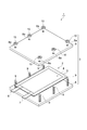
- FIG. 1 is an exploded perspective view showing a secondary battery according to one embodiment.
- a secondary battery 1 according to one embodiment includes a laminated battery 2 and a sandwiching member 3 that sandwiches the laminated battery 2.
- the laminated battery 2 includes an electrode group 4 composed of a positive electrode, a negative electrode, and an electrolyte layer, and a bag-shaped battery case 5 that houses the electrode group 4.
- the positive electrode and the negative electrode are provided with a positive electrode current collecting tab 6 and a negative electrode current collecting tab 7, respectively.
- the positive electrode current collecting tab 6 and the negative electrode current collecting tab 7 protrude from the inside of the battery outer package 5 to the outside so that the positive electrode and the negative electrode can be electrically connected to the outside of the laminated battery 2 respectively.
- the battery case 5 may be formed of, for example, a laminate film.
- the laminated film may be, for example, a laminated film in which a polymer film such as a polyethylene terephthalate (PET) film, a metal foil such as aluminum, copper, and stainless steel, and a sealant layer such as polypropylene are laminated in this order.
- PET polyethylene terephthalate
- metal foil such as aluminum, copper, and stainless steel
- a sealant layer such as polypropylene
- the holding member 3 includes a pair of substrates 8, a screw (bolt) 9 for fastening the substrates 8, 8, and a nut 10.
- a plurality of screws 9 are attached to one substrate 8, and a plurality of holes 8 a into which the plurality of screws 9 can be inserted are formed in the other substrate 8.
- the nut 10 is screwed into the screw 9 inserted into the hole 8a, whereby the substrates 8, 8 are tightened.
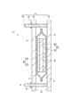
- FIG. 2 is a schematic sectional view showing the secondary battery 1.
- the electrode group 4 in the laminated battery 2 includes a positive electrode 41, an electrolyte layer 42, and a negative electrode 43 in this order.
- the positive electrode 41 includes a positive electrode current collector 44 and a positive electrode mixture layer 45 provided on the positive electrode current collector 44.
- the negative electrode 43 includes a negative electrode current collector 46 and a negative electrode mixture layer 47 provided on the negative electrode current collector 46.
- the positive electrode current collector 44 may be formed of aluminum, stainless steel, titanium, or the like. Specifically, the positive electrode current collector 44 may be, for example, an aluminum perforated foil having a hole diameter of 0.1 to 10 mm, an expanded metal, a foamed metal plate, or the like. In addition to the above, the positive electrode current collector 44 may be formed of any material as long as it does not cause a change such as dissolution and oxidation during use of the battery, and may have any shape, manufacturing method, and the like. Not restricted.
- the thickness of the positive electrode current collector 44 may be 10 ⁇ m or more, and may be 100 ⁇ m or less.
- the thickness of the positive electrode current collector 44 is preferably 10 ⁇ m or more and 50 ⁇ m or less from the viewpoint of reducing the volume of the entire positive electrode 41, and more preferably from the viewpoint of winding the positive electrode with a small curvature when forming a battery. 10 ⁇ m or more and 20 ⁇ m or less.
- the positive electrode mixture layer 45 contains a positive electrode active material and an ionic liquid.
- the positive electrode active material may be a lithium transition metal compound such as a lithium transition metal oxide and a lithium transition metal phosphate.
- the lithium transition metal oxide may be, for example, lithium manganate, lithium nickelate, lithium cobaltate, or the like.
- Lithium transition metal oxide a part of transition metal such as Mn, Ni, Co contained in lithium manganate, lithium nickelate, lithium cobaltate or the like, one or more other transition metals, or A lithium transition metal oxide substituted with a metal element (typical element) such as Mg or Al may be used. That is, the lithium transition metal oxide may be a compound represented by LiM 1 O 2 or LiM 1 O 4 (M 1 contains at least one transition metal).
- Lithium transition metal oxides specifically, Li (Co 1/3 Ni 1/3 Mn 1/3) O 2, LiNi 1/2 Mn 1/2 O 2, LiNi 1/2 Mn 3/2 O 4 or the like.
- the lithium transition metal oxide is preferably a compound represented by the following formula (1) from the viewpoint of further improving the energy density.
- the positive electrode active material may be ungranulated primary particles or granulated secondary particles.
- the particle size of the positive electrode active material is adjusted to be equal to or less than the thickness of the positive electrode mixture layer 45. If the positive electrode active material contains coarse particles having a particle size greater than or equal to the thickness of the positive electrode mixture layer 45, the coarse particles are removed in advance by sieving, airflow classification, or the like, and the particles having a thickness equal to or less than the thickness of the positive electrode mixture layer 45 are removed. A positive electrode active material having a diameter is selected.
- the average particle size of the positive electrode active material is preferably 0.1 ⁇ m or more, and more preferably 1 ⁇ m or more.
- the average particle size of the positive electrode active material is preferably 30 ⁇ m or less, and more preferably 25 ⁇ m or less.
- the average particle size of the positive electrode active material is a particle size (D 50 ) when the ratio (volume fraction) to the volume of the entire positive electrode active material is 50%.
- the average particle size (D 50 ) of the positive electrode active material is measured by using a laser scattering type particle size measuring device (for example, Microtrack) to measure the suspension of the positive electrode active material in water by a laser scattering method. It can be obtained by:
- the content of the positive electrode active material may be 70% by mass or more, 80% by mass or more, or 90% by mass or more based on the total amount of the positive electrode mixture layer.
- the content of the positive electrode active material may be 99% by mass or less based on the total amount of the positive electrode mixture layer.
- the ionic liquid contains the following anion component and cation component. Note that the ionic liquid in the present embodiment is a substance that is liquid at ⁇ 20 ° C. or higher.
- the anionic component of the ionic liquid is not particularly limited, but an anion of a halogen such as Cl ⁇ , Br ⁇ , or I ⁇ , an inorganic anion such as BF 4 ⁇ or N (SO 2 F) 2 — or B (C 6 H 5 ) 4 -, CH 3 SO 2 O -, CF 3 SO 2 O -, N (SO 2 C 4 F 9) 2 -, N (SO 2 CF 3) 2 -, N (SO 2 C 2 F 5) 2 - And the like.
- the anionic component of the ionic liquid preferably contains at least one anionic component represented by the following formula (I).
- m and n each independently represent an integer of 0 to 5.
- m and n may be the same or different from each other, and are preferably the same as each other.
- the anion components represented by the formula (I) include, for example, N (SO 2 C 4 F 9 ) 2 ⁇ , N (SO 2 F) 2 ⁇ , N (SO 2 CF 3 ) 2 ⁇ and N (SO 2 C 2 F 5) 2 - a.
- the anionic component of the ionic liquid is more preferably N (SO 2 C 4 F 9 ) 2 ⁇ , CF 3 SO from the viewpoint of further improving the ion conductivity at a relatively low viscosity and further improving the charge / discharge characteristics.
- [FSI] ⁇ N (SO 2 F) 2 ⁇ , bis (fluorosulfonyl) imide anion [TFSI] ⁇ : N (SO 2 CF 3 ) 2 ⁇ , bis (trifluoromethanesulfonyl) imide anion [BOB] ⁇ : B (O 2 C 2 O 2 ) 2 ⁇ , bisoxalate borate anion [f3C] ⁇ : C (SO 2 F) 3 ⁇ , tris (fluorosulfonyl) carbanion
- the cation component of the ionic liquid is preferably at least one selected from the group consisting of chain quaternary onium cations, piperidinium cations, pyrrolidinium cations, pyridinium cations, and imidazolium cations.
- the chain quaternary onium cation is, for example, a compound represented by the following formula (II).
- R 11 to R 14 each independently represent a chain alkyl group having 1 to 20 carbon atoms or a chain alkoxyalkyl group represented by RO— (CH 2 ) n — ( R represents a methyl group or an ethyl group, n represents an integer of 1 to 4), and X represents a nitrogen atom or a phosphorus atom.
- the alkyl group represented by R 11 to R 14 preferably has 1 to 20, more preferably 1 to 10, and still more preferably 1 to 5 carbon atoms.
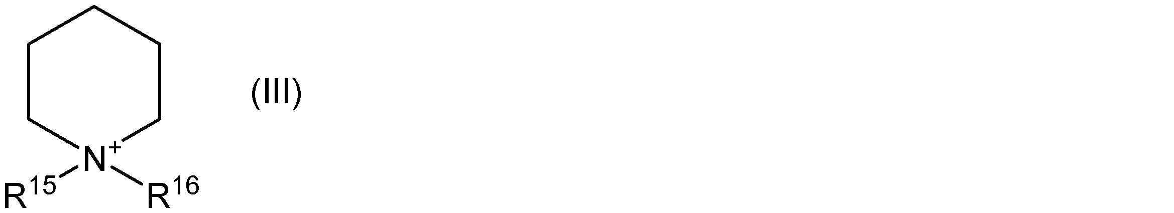
- the piperidinium cation is, for example, a nitrogen-containing six-membered cyclic compound represented by the following formula (III).
- R 15 and R 16 are each independently an alkyl group having 1 to 20 carbon atoms or an alkoxyalkyl group represented by RO— (CH 2 ) n — (R is a methyl group Or n represents an ethyl group, and n represents an integer of 1 to 4).
- the carbon number of the alkyl group represented by R 15 and R 16 is preferably 1 to 20, more preferably 1 to 10, and still more preferably 1 to 5.
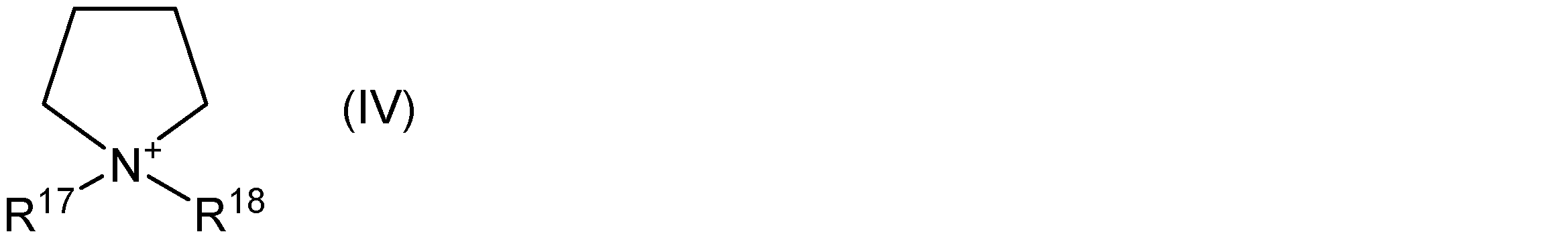
- the pyrrolidinium cation is, for example, a five-membered cyclic compound represented by the following formula (IV).
- R 17 and R 18 are each independently an alkyl group having 1 to 20 carbon atoms or an alkoxyalkyl group represented by RO— (CH 2 ) n — (R is a methyl group Or n represents an ethyl group, and n represents an integer of 1 to 4).
- the carbon number of the alkyl group represented by R 17 and R 18 is preferably 1 to 20, more preferably 1 to 10, and still more preferably 1 to 5.
- the pyridinium cation is, for example, a compound represented by the following formula (V).
- R 19 to R 23 each independently represent an alkyl group having 1 to 20 carbon atoms, an alkoxyalkyl group represented by RO— (CH 2 ) n — (R represents a methyl group or Represents an ethyl group, and n represents an integer of 1 to 4) or a hydrogen atom.
- the alkyl group represented by R 19 to R 23 preferably has 1 to 20, more preferably 1 to 10, and still more preferably 1 to 5 carbon atoms.
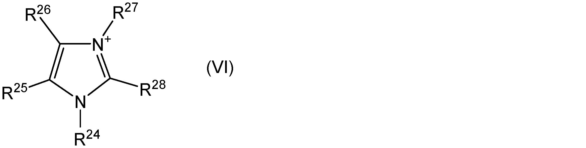
- the imidazolium cation is, for example, a compound represented by the following formula (VI).
- R 24 ⁇ R 28 each independently represent an alkyl group having a carbon number of 1 ⁇ 20, R-O- ( CH 2) n - alkoxyalkyl group (R represented by a methyl group or Represents an ethyl group, and n represents an integer of 1 to 4) or a hydrogen atom.
- the carbon number of the alkyl group represented by R 24 to R 28 is preferably 1 to 20, more preferably 1 to 10, and still more preferably 1 to 5.
- the content of the ionic liquid is preferably 3% by mass or more, more preferably 5% by mass or more, and further preferably 10% by mass or more, based on the total amount of the positive electrode mixture layer.
- the content of the ionic liquid is preferably 30% by mass or less, more preferably 25% by mass or less, and still more preferably 20% by mass or less, based on the total amount of the positive electrode mixture layer.
- the positive electrode mixture layer 45 may further contain a conductive material, a binder and the like.
- the conductive material is not particularly limited, but may be a carbon material such as graphite, acetylene black, carbon black, carbon fiber, carbon nanotube, or the like.
- the conductive material may be a mixture of two or more of the above-described carbon materials.
- the content of the conductive material may be 0.1% by mass or more, 1% by mass or more, or 3% by mass or more, 15% by mass or less, 10% by mass or less, or 8% by mass based on the total amount of the positive electrode mixture layer. % By mass or less.
- the binder is not particularly limited, and contains, as monomer units, at least one selected from the group consisting of ethylene tetrafluoride, vinylidene fluoride, hexafluoropropylene, acrylic acid, maleic acid, ethyl methacrylate, and methyl methacrylate. It may be a rubber such as a polymer, styrene-butadiene rubber, isoprene rubber, and acrylic rubber.
- the binder is preferably a copolymer containing ethylene tetrafluoride and vinylidene fluoride as structural units, or a copolymer containing vinylidene fluoride and hexafluoropropylene as structural units.
- the content of the binder may be 0.5% by mass or more, 1% by mass or more, or 3% by mass or more based on the total amount of the positive electrode mixture layer.
- the content of the binder may be 20% by mass or less, 15% by mass or less, or 10% by mass or less based on the total amount of the positive electrode mixture layer.
- An electrolyte salt may be dissolved in the ionic liquid.
- the electrolyte salt may be at least one selected from the group consisting of a lithium salt, a sodium salt, a calcium salt, and a magnesium salt.
- the anion components of the electrolyte salt include halide ions (I ⁇ , Cl ⁇ , Br ⁇ , etc.), SCN ⁇ , BF 4 ⁇ , BF 3 (CF 3 ) ⁇ , BF 3 (C 2 F 5 ) ⁇ , PF 6 ⁇ , ClO 4 ⁇ , SbF 6 ⁇ , N (SO 2 F) 2 ⁇ , N (SO 2 CF 3 ) 2 ⁇ , N (SO 2 C 2 F 5 ) 2 ⁇ , B (C 6 H 5 ) 4 ⁇ , B (O 2 C 2 H 4 ) 2 ⁇ , C (SO 2 F) 3 ⁇ , C (SO 2 CF 3 ) 3 ⁇ , CF 3 COO ⁇ , CF 3 SO 2 O ⁇ , C 6 F 5 SO 2 O — , B (O 2 C 2 O 2 ) 2 — and the like.
- halide ions I ⁇ , Cl ⁇ , Br
- the anion component of the electrolyte salt is preferably an anion component represented by the above formula (I) such as N (SO 2 F) 2 ⁇ , N (SO 2 CF 3 ) 2 ⁇ , PF 6 ⁇ , BF 4 ⁇ , B (O 2 C 2 O 2 ) 2 ⁇ , or ClO 4 — .
- Lithium salt LiPF 6, LiBF 4, Li [FSI], Li [TFSI], Li [f3C], Li [BOB], LiClO 4, LiBF 3 (CF 3), LiBF 3 (C 2 F 5), LiBF 3 (C 3 F 7 ), LiBF 3 (C 4 F 9 ), LiC (SO 2 CF 3 ) 3 , LiCF 3 SO 2 O, LiCF 3 COO, and LiRCOO (R is an alkyl group having 1 to 4 carbon atoms) , A phenyl group or a naphthyl group.).
- Calcium salts include Ca (PF 6 ) 2 , Ca (BF 4 ) 2 , Ca [FSI] 2 , Ca [TFSI] 2 , Ca [f3C] 2 , Ca [BOB] 2 , Ca (ClO 4 ) 2 , Ca [BF 3 (CF 3 )] 2 , Ca [BF 3 (C 2 F 5 )] 2 , Ca [BF 3 (C 3 F 7 )] 2 , Ca [BF 3 (C 4 F 9 )] 2 , Ca [C (SO 2 CF 3 ) 3 ] 2 , Ca (CF 3 SO 2 O) 2 , Ca (CF 3 COO) 2 and Ca (RCOO) 2 (R is an alkyl group having 1 to 4 carbon atoms, phenyl Or a naphthyl group).
- Magnesium salts include Mg (PF 6 ) 2 , Mg (BF 4 ) 2 , Mg [FSI] 2 , Mg [TFSI] 2 , Mg [f3C] 2 , Mg [BOB] 2 , Na (ClO 4 ) 2 , Mg [BF 3 (CF 3)] 2, Mg [BF 3 (C 2 F 5)] 2, Mg [BF 3 (C 3 F 7)] 2, Mg [BF 3 (C 4 F 9)] 2, Mg [C (SO 2 CF 3 ) 3 ] 2 , Mg (CF 3 SO 3 ) 2 , Mg (CF 3 COO) 2 , and Mg (RCOO) 2 (R is an alkyl group having 1 to 4 carbon atoms, a phenyl group Or a naphthyl group.).
- the electrolyte salt is preferably LiPF 6 , LiBF 4 , Li [FSI], Li [TFSI], Li [f3C], Li [BOB], or LiClO 4.
- LiRCOO R is an alkyl group having 1 to 4 carbon atoms, a phenyl group or a naphthyl group
- the thickness of the positive electrode mixture layer 45 may be 10 ⁇ m or more, 15 ⁇ m or more, or 20 ⁇ m or more.
- the thickness of the positive electrode mixture layer 45 may be 100 ⁇ m or less, 80 ⁇ m or less, or 70 ⁇ m or less.
- the negative electrode current collector 46 may be a metal such as aluminum, copper, nickel, and stainless steel, or an alloy thereof.
- the negative electrode current collector 46 is preferably aluminum and its alloy because it is lightweight and has a high weight energy density.
- the negative electrode current collector 46 is preferably made of copper from the viewpoint of ease of processing into a thin film and cost.
- the thickness of the negative electrode current collector 46 may be 10 ⁇ m or more, and may be 100 ⁇ m or less.
- the thickness of the negative electrode current collector 46 is preferably 10 ⁇ m or more and 50 ⁇ m or less from the viewpoint of reducing the volume of the entire negative electrode, and more preferably 10 ⁇ m from the viewpoint of winding the negative electrode with a small curvature when forming a battery. Not less than 20 ⁇ m.
- the negative electrode mixture layer 47 contains a negative electrode active material and an ionic liquid.
- the negative electrode active material those commonly used in the field of energy devices can be used.
- the negative electrode active material include lithium metal, lithium titanate (Li 4 Ti 5 O 12 ), a lithium alloy or another metal compound, a carbon material, a metal complex, and an organic polymer compound.
- the negative electrode active material may be one of these alone or a mixture of two or more thereof.
- the carbon material include natural graphite (flaky graphite, etc.), graphite such as artificial graphite (graphite), amorphous carbon, carbon fiber, acetylene black, Ketjen black, channel black, furnace black, lamp black, and thermal black. And the like. From the viewpoint of obtaining a larger theoretical capacity (for example, 500 to 1500 Ah / kg), the negative electrode active material may be silicon, tin, or a compound containing these elements (oxide, nitride, alloy with another metal). Good.
- the average particle size (D 50 ) of the negative electrode active material is preferably 1 ⁇ m or more from the viewpoint of obtaining a well-balanced negative electrode having an increased irreversible capacity due to a decrease in particle size and an increased ability to retain an electrolyte salt. And more preferably 5 ⁇ m or more, further preferably 10 ⁇ m or more, and preferably 50 ⁇ m or less, more preferably 40 ⁇ m or less, and still more preferably 30 ⁇ m or less.
- the average particle size of the negative electrode active material (D 50) is measured in the same manner as the average particle diameter of the above-mentioned positive electrode active material (D 50).
- the content of the negative electrode active material may be 60% by mass or more, 65% by mass or more, or 70% by mass or more based on the total amount of the negative electrode mixture layer.
- the content of the negative electrode active material may be 99% by mass or less, 95% by mass or less, or 90% by mass or less based on the total amount of the negative electrode mixture layer.
- the ionic liquid may be the ionic liquid described above as the ionic liquid contained in the positive electrode mixture layer 45.
- the content of the ionic liquid is preferably 3% by mass or more, more preferably 5% by mass or more, and still more preferably 10% by mass or more, based on the total amount of the negative electrode mixture layer.
- the content of the ionic liquid is preferably 30% by mass or less, more preferably 25% by mass or less, and still more preferably 20% by mass or less, based on the total amount of the negative electrode mixture layer.
- An electrolyte salt similar to the electrolyte salt that can be used for the positive electrode mixture layer 45 described above may be dissolved in the ionic liquid.
- the negative electrode mixture layer 47 may further contain a conductive material, a binder, and the like that can be used for the positive electrode mixture layer 45 described above.
- the contents of the conductive material and the binder contained in the negative electrode mixture layer 47 may be the same as the contents of the conductive material and the binder in the positive electrode mixture layer 45 described above.
- the thickness of the negative electrode mixture layer 47 may be 10 ⁇ m or more, 15 ⁇ m or more, or 20 ⁇ m or more.
- the thickness of the negative electrode mixture layer 47 may be 100 ⁇ m or less, 80 ⁇ m or less, or 70 ⁇ m or less.
- the electrolyte layer 42 includes, in one embodiment, a polymer, oxide particles, an electrolyte salt, and an ionic liquid.
- the polymer preferably has a first structural unit selected from the group consisting of ethylene tetrafluoride and vinylidene fluoride.
- the polymer is preferably one or more polymers, and among the structural units constituting the one or more polymers, the first structural unit includes hexafluoropropylene, acrylic acid, and maleic acid.
- a second structural unit selected from the group consisting of an acid, ethyl methacrylate, and methyl methacrylate may be included. That is, the first structural unit and the second structural unit may be included in one kind of polymer to constitute a copolymer, and each of the first structural unit and the second structural unit may be included in another polymer and have the first structural unit having the first structural unit. And a second polymer having a second structural unit.
- the polymer may be polytetrafluoroethylene, polyvinylidene fluoride, a copolymer of vinylidene fluoride and hexafluoropropylene, or the like.
- the content of the polymer is preferably 3% by mass or more based on the total amount of the electrolyte layer.
- the content of the polymer is preferably 50% by mass or less, more preferably 40% by mass or less, based on the total amount of the electrolyte layer.
- the content of the polymer is preferably 3 to 50% by mass, or 3 to 40% by mass, based on the total amount of the electrolyte layer.
- the polymer Since the polymer has excellent affinity with the ionic liquid contained in the electrolyte layer 42, the polymer can suitably hold the ionic liquid, and as a result, the electrolyte salt in the ionic liquid can also be held. Thereby, leakage of the ionic liquid when a load is applied to the electrolyte layer 42 is suppressed.
- the oxide particles are, for example, particles of an inorganic oxide.
- the inorganic oxide is an inorganic oxide containing, for example, Li, Mg, Al, Si, Ca, Ti, Zr, La, Na, K, Ba, Sr, V, Nb, B, Ge, or the like as a constituent element. Good.
- the oxide particles are preferably at least one selected from the group consisting of SiO 2 , Al 2 O 3 , AlOOH, MgO, CaO, ZrO 2 , TiO 2 , Li 7 La 3 Zr 2 O 12 , and BaTiO 3 . Particles. Since the oxide particles have polarity, dissociation of the electrolyte salt in the electrolyte layer 42 can be promoted, and battery characteristics can be improved.
- the oxide particles may be a rare earth metal oxide.
- the oxide particles include scandium oxide, yttrium oxide, lanthanum oxide, cerium oxide, praseodymium oxide, neodymium oxide, samarium oxide, eurobium oxide, gadolinium oxide, terbium oxide, dysprosium oxide, holmium oxide, erbium oxide, and oxide oxide. It may be thulium, ytterbium oxide, lutetium oxide, or the like.
- the specific surface area of the oxide particles is preferably 5 m 2 / g or more, 10 m 2 / g or more, or 15 m 2 / g or more, and more preferably 100 m 2 / g, from the viewpoint of excellent discharge characteristics of the secondary battery.
- it is 80 m ⁇ 2 > / g or less, or 60 m ⁇ 2 > / g or less.
- the specific surface area of the oxide particles means the specific surface area of the entire oxide particles including the primary particles and the secondary particles, and is measured by a BET method.
- the average particle size of the oxide particles is preferably 0.005 ⁇ m or more, more preferably 0.01 ⁇ m or more, and further preferably 0.03 ⁇ m or more.
- the average particle size of the oxide particles is preferably 5 ⁇ m or less, more preferably 3 ⁇ m or less, and still more preferably 1 ⁇ m or less.
- the average particle size of the oxide particles is measured by a laser diffraction method, and corresponds to a particle size at which the volume accumulation becomes 50% when a volume accumulation particle size distribution curve is drawn from the small particle size side.
- the content of the oxide particles is preferably 5% by mass or more, more preferably 10% by mass or more, still more preferably 15% by mass or more, particularly preferably 20% by mass or more, based on the total amount of the electrolyte layer. It is preferably at most 60% by mass, more preferably at most 50% by mass, even more preferably at most 40% by mass.
- the electrolyte salt may be at least one selected from the group consisting of lithium salt, sodium salt, calcium salt and magnesium salt.
- the electrolyte salt may be the same as the electrolyte salt that can be used for the positive electrode mixture layer 45 and the negative electrode mixture layer 47.
- the ionic liquid may be the ionic liquid described above as the ionic liquid contained in the positive electrode mixture layer 45.
- An electrolyte salt may be dissolved in the ionic liquid.
- the concentration of the electrolyte salt per unit volume of the ionic liquid is preferably 0.5 mol / L or more, more preferably 0.7 mol / L or more, and still more preferably 0.8 mol / L, from the viewpoint of further improving the charge / discharge characteristics. It is preferably 2.0 mol / L or less, more preferably 1.8 mol / L or less, and still more preferably 1.5 mol / L or less.
- the content of the ionic liquid may be 10% by mass or more and 80% by mass or less based on the total amount of the electrolyte layer from the viewpoint of suitably producing the electrolyte layer 42.
- the total content of the electrolyte salt and the ionic liquid is preferably 10% by mass or more, more preferably 10% by mass or more, based on the total amount of the electrolyte layer, from the viewpoint of further improving the conductivity and suppressing a decrease in the capacity of the secondary battery. Is at least 25% by mass, more preferably at least 40% by mass.
- the total content of the electrolyte salt and the ionic liquid is preferably 80% by mass or less, based on the total amount of the electrolyte layer, from the viewpoint of suppressing a decrease in the strength of the electrolyte layer.
- the thickness of the electrolyte layer 42 is preferably 5 ⁇ m or more, more preferably 10 ⁇ m or more, from the viewpoint of increasing strength and improving safety.
- the thickness of the electrolyte layer 42 is preferably 200 ⁇ m or less, more preferably 150 ⁇ m or less, and still more preferably 100 ⁇ m or less, from the viewpoint of further reducing the internal resistance of the secondary battery and further improving the large current characteristics.
- the clamping members 3 clamp the laminated battery 2 by tightening the substrates 8 with the screws 9 and the nuts 10.
- the positive electrode 41, the electrolyte layer 42, and the negative electrode 43 in the laminated battery 2 are in a pressurized state pressed in the stacking direction D1, and the holding member 3 functions as a holding unit that holds the pressurized state. I do.
- the positive electrode 41, the electrolyte layer 42, and the negative electrode 43 may have a pressure of, for example, 0.1 MPa or more, and are preferably 0.2 MPa or more, 0.4 MPa or more, from the viewpoint of further improving initial characteristics.
- a pressure of 0.5 MPa or more, more preferably 0.7 MPa or more, 0.8 MPa or more, 0.9 MPa or more, or 1.0 MPa or more is applied.
- the pressurized state of the positive electrode 41, the electrolyte layer 42, and the negative electrode 43 is held by the sandwiching member 3 (holding means), so that the positive electrode 41 (the positive electrode mixture layer 45) and the electrolyte layer 42
- the interface and the interface between the negative electrode 43 (negative electrode mixture layer 47) and the electrolyte layer 42 are formed well (adhesion at the interface is improved), and as a result, the secondary battery 1 (laminated battery 2) having excellent initial characteristics is obtained. ) Is considered to be obtained.
- the holding member 3 functions as a holding unit.
- a thermoplastic resin, a thermosetting resin, or the like may be used as the holding unit.
- a resin material such as a resin and a photocurable resin can be used.
- the pressurized state of the positive electrode 41, the electrolyte layer 42, and the negative electrode 43 may be maintained.
- the pressurized state of the positive electrode 41, the electrolyte layer 42, and the negative electrode 43 may be maintained by, for example, arranging and solidifying a resin material so as to cover the entire laminated battery 2.
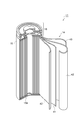
- FIG. 3 is a perspective view showing the overall configuration and internal structure of a secondary battery according to another embodiment.
- the secondary battery 11 includes an electrode group 14, a cylindrical battery container 15 that houses the electrode group 14 and has an open top surface, and a lid 16 that closes the opening of the battery container 15.
- It is a secondary battery of a round type (also called a 18650 type or a cylindrical type).
- the electrode group 14 includes a long positive electrode 41, an electrolyte layer 42, and a negative electrode 43 in this order.
- An insulating coating (not shown) is provided on the entire outer peripheral surface of the electrode group 14.
- the battery container 15 may be, for example, a nickel-plated steel container.
- the lid 16 is caulked and fixed to the upper part of the battery container 15 via, for example, an insulating resin gasket.
- the positive electrode 41 and the negative electrode 43 are provided with a positive electrode current collecting tab and a negative electrode current collecting tab (not shown) so that the positive electrode 41 and the negative electrode 43 can be electrically connected to the outside of the secondary battery 11, respectively.
- One end of the positive electrode current collection tab is joined to the lower surface of the lid 16 of the secondary battery 11 by, for example, ultrasonic welding.
- One end of the negative electrode current collecting tab is joined to the inner bottom portion 15a of the battery container 15 by, for example, resistance welding.
- the positive current collecting tab is formed of aluminum and the negative current collecting tab is formed of copper.
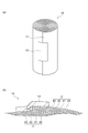
- FIG. 4 (a) is a perspective view showing the electrode group 14 shown in FIG. 3, and FIG. 4 (b) is a schematic sectional view showing a main part of the electrode group 14.
- the electrode group 14 is formed by spirally winding a long laminate 17.
- the laminate 17 includes, for example, an electrolyte layer 42, a positive electrode 41, an electrolyte layer 42, and a negative electrode 43 in this order from the inside of the spiral.
- a fixing member 13 for fixing the front end of the stacked body 17 to the stacked body 17 located immediately below is provided.
- the fixing member 13 may be a stickable member such as an adhesive tape, for example, or may be a member obtained by solidifying a resin material such as a thermoplastic resin, a thermosetting resin, and a photocurable resin.
- the fixing member 13 functions as a holding unit that holds the stacked body 17 in a pressurized state by fixing the front end of the stacked body 17.
- the manufacturing method includes a pressing step of pressing a stacked body including the positive electrode 41, the electrolyte layer 42, and the negative electrode 43 in this order in a stacking direction, and a holding unit that holds a pressed state of the pressed stacked body. And a holding step of providing.
- the laminate includes a positive electrode 41 obtained by forming a positive electrode mixture layer 45 on a positive electrode current collector 44 and a negative electrode composite on a negative electrode current collector 46. It is produced by providing the electrolyte layer 42 between the negative electrode 43 obtained by forming the agent layer 47.
- the laminate is obtained, for example, in the same manner as described above, with the first laminate in which the electrolyte layer 42 is laminated on the positive electrode 41 obtained in the same manner as described above.
- the second laminate in which the electrolyte layer 42 is laminated on the negative electrode 43 is further laminated so that the positive electrode 41 in the first laminate and the electrolyte layer 42 in the second laminate are in contact with each other. .
- the positive electrode mixture layer 45 is formed, for example, by applying a slurry-like positive electrode mixture in which the above-described material used for the positive electrode mixture layer 45 is dispersed in a dispersion medium to one surface of the positive electrode current collector 44. Thereafter, it is obtained by volatilizing the dispersion medium (the same applies to the negative electrode mixture layer 47).
- the dispersion medium may be, for example, an organic solvent such as N-methyl-2-pyrrolidone.
- the electrolyte layer 42 is provided on the positive electrode 41, the negative electrode 43, or between the positive electrode 41 and the negative electrode 43 after being formed in advance on the sheet-like electrolyte layer.
- an electrolyte slurry in which the above-described material used for the electrolyte layer is dispersed in a dispersion medium is applied on a substrate, and then the dispersion medium is volatilized to obtain a sheet-like electrolyte layer.
- the dispersion medium may be, for example, water, NMP, toluene and the like.
- the electrolyte layer By pressing this electrolyte layer in a state where it is overlapped so as to be in contact with the positive electrode mixture layer 45 and / or the negative electrode mixture layer 47, the electrolyte is formed on the positive electrode 41, the negative electrode 43, or between the positive electrode 41 and the negative electrode 43.
- a layer 42 can be provided.
- the electrolyte layer 42 is formed by applying an electrolyte slurry in which the above-described material used for the electrolyte layer is dispersed in a dispersion medium to the positive electrode mixture layer 45 and / or the negative electrode mixture layer 47 and drying the mixture. Obtained by:
- the content of the polymer in the electrolyte slurry may be 3% by mass or more, or 50% by mass or less or 40% by mass based on the total amount of non-volatile components (components excluding the dispersion medium from the electrolyte slurry) in the electrolyte slurry. %.
- the content of the oxide particles in the electrolyte slurry may be 5% by mass or more, 10% by mass or more, 15% by mass or more, or 20% by mass or more, based on the total amount of nonvolatile components in the electrolyte slurry, It may be 60% by mass or less, 50% by mass or less, or 40% by mass or less.
- the total content of the ionic liquid and the electrolyte salt in the electrolyte slurry may be 90% by mass or less, 85% by mass or less, or 80% by mass or less based on the total amount of nonvolatile components in the electrolyte slurry.
- the content of the dispersion medium in the electrolyte slurry may be, for example, 5 parts by mass or more and 1000 parts by mass or less based on 100 parts by mass of the nonvolatile components in the electrolyte slurry.
- the pressing step pressure is applied in the stacking direction of the stacked body.
- the laminates the positive electrode 41
- the sandwiching members 3 by clamping the substrates 8, 8 with the screws 9 and the nuts 10.
- the electrolyte layer 42 and the negative electrode 43 are pressed in the stacking direction D1.
- the laminate 17 when the laminate 17 is wound into a spiral shape, by applying a winding tension, the laminate 17 (the electrolyte layer 42, the positive electrode 41, the electrolyte The layer 42 and the negative electrode 43) are pressed in the stacking direction D2.
- the pressure in the pressurizing step may be, for example, 0.1 MPa or more, from the viewpoint of further improving the initial characteristics of the secondary battery, preferably 0.2 MPa or more, 0.4 MPa or more, or 0.5 MPa or more, More preferably, it is 0.7 Mpa or more, 0.8 MPa or more, 0.9 MPa or more, or 1.0 MPa or more.
- a holding means for holding the pressure applied in the pressing step is provided.
- the pressurized state of the laminate is maintained by maintaining the state. That is, in the manufacture of the secondary battery 1 shown in FIGS. 1 and 2, the pressurizing step and the holding step are performed substantially continuously (substantially simultaneously).
- the tip of the stacked body 17 is fixed by the fixing member 13, so that the stacked body 17 is applied. Maintain pressure state.
- the method for manufacturing a secondary battery preferably further includes a step of heating the laminate after the holding step, from the viewpoint of further improving the initial characteristics of the secondary battery.
- the laminate is heated while maintaining the pressurized state, so that the interface between the positive electrode 41 (the positive electrode mixture layer 45) and the electrolyte layer 42, and the negative electrode 43 (the negative electrode mixture layer 47) and the electrolyte layer It is considered that the interface with the interface 42 is formed more favorably (adhesion at the interface is further improved).
- the heating temperature in the heating step is preferably 25 ° C. or higher, more preferably 40 ° C. or higher, still more preferably 50 ° C. or higher, and particularly preferably 60 ° C. or higher, from the viewpoint of improving the discharge characteristics of the secondary battery.
- the heating temperature in the heating step may be, for example, 100 ° C. or lower, and is preferably 90 ° C. or lower, more preferably 80 ° C. or lower, from the viewpoint of improving the discharge characteristics of the secondary battery.
- Example 1 ⁇ Preparation of positive electrode> 79.6 parts by mass of layered lithium-nickel-manganese-cobalt composite oxide (positive electrode active material), acetylene black (conductive material, average particle size 48 nm, specific surface area 39 m 2 / g, manufactured by Denka Corporation, trade name: HS-100) 3.87 parts by mass, acetylene black (conductive material, average particle size 23 nm, specific surface area 133 m 2 / g, manufactured by Denka Corporation) 0.43 parts by mass, copolymer of vinylidene fluoride and hexafluoropropylene (Binder) 2.1 parts by mass and an ionic liquid (N-methyl-N-propylpyrrolidinium bis) in which lithium salt (lithium bis (fluoromethanesulfonyl) imide (LiFSI)) is dissolved at 1 mol / L.
- positive electrode active material positive electrode active material
- acetylene black conductive material
- This negative electrode mixture was coated on a negative electrode current collector (a copper foil having a thickness of 10 ⁇ m) at a coating amount of 73 g / m 2 , and heated at 80 ° C. to volatilize the dispersion medium. Then, the mixture was compacted to a mixture density of 1.90 g / cm 3 by pressing to form a negative electrode mixture layer (thickness: 38 ⁇ m). The obtained laminate was punched into a square of 3.1 cm ⁇ 4.6 cm to obtain a negative electrode.
- a negative electrode current collector a copper foil having a thickness of 10 ⁇ m 2
- ⁇ Preparation of electrolyte layer 40 parts by mass of SiO 2 particles (average particle size 0.04 ⁇ m, specific surface area 50 m 2 / g) and 60 parts by mass of a copolymer of vinylidene fluoride and hexafluoropropylene are mixed, and then NMP as a dispersion medium is added. Then, a mixture of SiO 2 particles and a copolymer was obtained by kneading. LiFSI (electrolyte salt) dried under a dry argon atmosphere was dissolved in Py13-FSI (ionic liquid) at a concentration of 1.5 mol / L.
- a mixture of SiO 2 particles and a copolymer was mixed with an ionic liquid in which an electrolyte salt was dissolved to prepare an electrolyte slurry.
- the obtained slurry was applied to a polyethylene terephthalate base material (thickness: 40 ⁇ m) and heated to evaporate the dispersion medium to obtain an electrolyte layer (electrolyte sheet).
- the thickness of the obtained electrolyte layer was 20 ⁇ 5 ⁇ m.
- a laminate was prepared by laminating the positive electrode, the electrolyte layer, and the negative electrode produced in the above order in this order.
- This laminate was placed in an aluminum laminate container (product name: aluminum laminate film, manufactured by Dai Nippon Printing Co., Ltd.), and the laminate container was evacuated and thermally welded to produce a laminate type battery for evaluation.
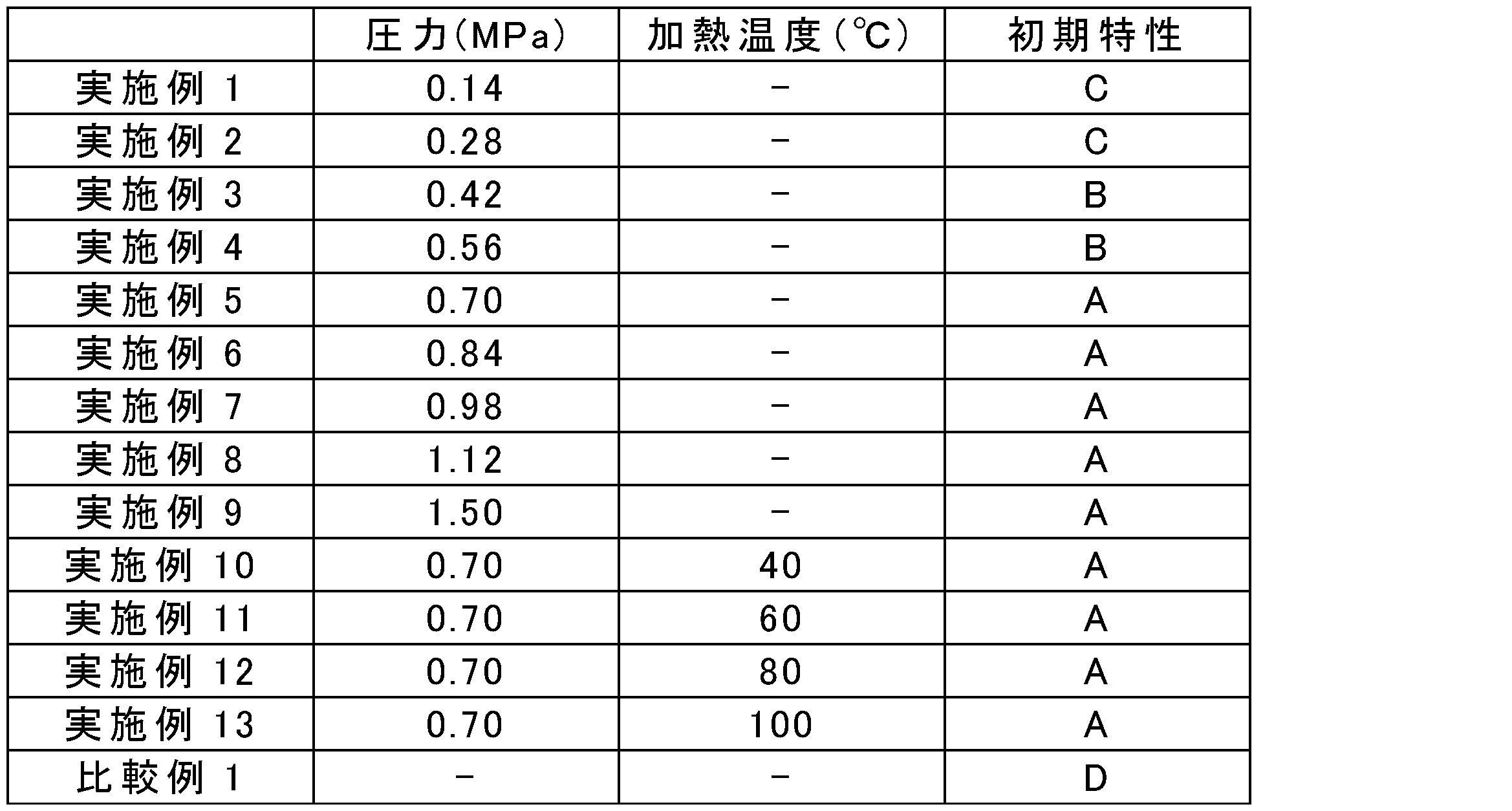
- ⁇ Pressure of laminated battery> The laminated battery manufactured as described above is clamped by a clamping member (made of SUS) as shown in FIG. 1, a pressure of 0.14 MPa is applied at 25 ° C. in a lamination direction of the laminate, and the battery is tightened with a screw and a nut. A secondary battery in which the state was maintained was obtained. At this time, in order to prevent a short circuit of the secondary battery, the current collecting tab was prevented from directly contacting the holding member. Note that a spring was arranged between the substrate and the nut of the holding member, and the magnitude of the pressure was adjustable.
- Examples 2 to 9 A secondary battery was fabricated in the same manner as in Example 1, except that the pressure during pressurization was changed to the pressure shown in Table 1.
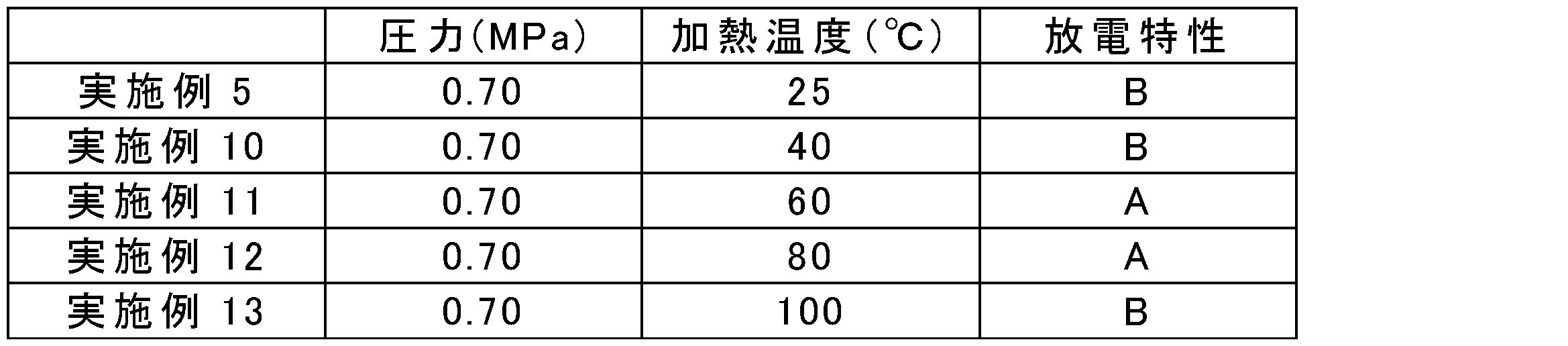
- Example 10 to 13 A secondary battery was fabricated in the same manner as in Example 5, except that the laminated battery was sandwiched between sandwiching members and the pressurized state was maintained, and the secondary battery was heated at the temperature shown in Table 1 for 30 minutes.
- 1,11 secondary battery, 3,13 holding means 41 positive electrode, 42 electrolyte layer, 43 negative electrode, 44 positive electrode current collector, 45 positive electrode mixture layer, 46 negative electrode current collector, 47 ... Negative electrode mixture layer.
Abstract
本発明の一側面は、正極と、電解質層と、負極とを備える二次電池であって、正極、電解質層及び負極は、この順に積層され、かつ積層方向に加圧された加圧状態にあり、加圧状態を保持する保持手段を更に備える、二次電池である。
Description
本開示は、二次電池及びその製造方法に関する。
近年、携帯型電子機器、電気自動車等の普及により、高性能な二次電池が必要とされている。中でもリチウム二次電池は、高いエネルギ密度を有するため、携帯型電子機器、電気自動車等の電源として利用されている。リチウム二次電池には高い安全性が求められており、その手段として、全固体電池の開発が進められている。
全固体電池においては、電解液の代わりに、ポリマ電解質又は無機固体電解質といった固体電解質の層(電解質層)が電極合剤層上に設けられている(例えば特許文献1)。このような全固体電池においては、電解質層に溶媒が添加される場合がある。例えば、特許文献2には、ポリマ電解質等の電解質層にイオン液体が含まれた二次電池が開示されている。
上述したような二次電池においては、より高い性能が求められており、初期の放電容量(初期容量)が設計容量にできる限り近い、いわゆる初期特性に優れるリチウム二次電池の開発が望まれている。そこで、本発明は、初期特性に優れる二次電池及びその製造方法を提供することを目的とする。
本発明の一側面は、正極と、電解質層と、負極とを備える二次電池であって、正極、電解質層及び負極は、この順に積層され、かつ積層方向に加圧された加圧状態にあり、加圧状態を保持する保持手段を更に備える、二次電池である。
正極、電解質層及び負極は、積層方向に0.7MPa以上で加圧されていてよい。
本発明の他の一側面は、正極、電解質層及び負極をこの順に備える積層体を積層方向に加圧する加圧工程と、加圧された積層体の加圧状態を保持する保持手段を設ける保持工程と、を備える、二次電池の製造方法である。
加圧工程において、積層体を積層方向に0.7MPa以上で加圧してよい。上記製造方法は、保持工程の後に、積層体を50℃以上で加熱する工程を更に備えてよい。
上記各側面において、電解質層は、ポリマと、酸化物粒子と、電解質塩と、イオン液体とを含有してよい。正極は、正極集電体と、正極集電体上に設けられた正極合剤層とを備え、正極合剤層は、正極活物質と、イオン液体とを含有してよい。負極は、負極集電体と、負極集電体上に設けられた負極合剤層とを備え、負極合剤層は、負極活物質と、イオン液体とを含有してよい。
本発明によれば、初期特性に優れる二次電池及びその製造方法を提供することができる。
以下、図面を適宜参照しながら、本発明の実施形態について説明する。ただし、本発明は以下の実施形態に限定されるものではない。以下の実施形態において、その構成要素(ステップ等も含む)は、特に明示した場合を除き、必須ではない。各図における構成要素の大きさは概念的なものであり、構成要素間の大きさの相対的な関係は各図に示されたものに限定されない。また、図面の説明において同一の要素には同一の符号を付し、重複する説明を省略する。
本明細書における数値及びその範囲は、本発明を制限するものではない。本明細書において「~」を用いて示された数値範囲は、「~」の前後に記載される数値をそれぞれ最小値及び最大値として含む範囲を示す。本明細書において段階的に記載されている数値範囲において、一つの数値範囲で記載された上限値又は下限値は、他の段階的な記載の上限値又は下限値に置き換えてもよい。また、本明細書中に記載される数値範囲において、その数値範囲の上限値又は下限値は、実施例に示されている値に置き換えてもよい。
図1は、一実施形態に係る二次電池を示す分解斜視図である。図1に示すように、一実施形態に係る二次電池1は、ラミネート型電池2と、ラミネート型電池2を挟持する挟持部材3とを備えている。
ラミネート型電池2は、正極、負極及び電解質層から構成される電極群4と、電極群4を収容する袋状の電池外装体5とを備えている。正極及び負極には、それぞれ正極集電タブ6及び負極集電タブ7が設けられている。正極集電タブ6及び負極集電タブ7は、それぞれ正極及び負極がラミネート型電池2の外部と電気的に接続可能なように、電池外装体5の内部から外部へ突き出している。
電池外装体5は、例えばラミネートフィルムで形成されていてよい。ラミネートフィルムは、例えば、ポリエチレンテレフタレート(PET)フィルム等のポリマフィルムと、アルミニウム、銅、ステンレス鋼等の金属箔と、ポリプロピレン等のシーラント層とがこの順で積層された積層フィルムであってよい。
挟持部材3は、一対の基板8,8と、基板8,8同士を締め付けるネジ(ボルト)9及びナット10とで構成されている。例えば、一方の基板8に複数のネジ9が取り付けられており、他方の基板8には、複数のネジ9をそれぞれ挿入可能な複数の穴8aが形成されている。ナット10は、穴8aに挿入されたネジ9に螺合され、これにより基板8,8同士が締め付けられる。
図2は、二次電池1を示す模式断面図である。図2に示すように、ラミネート型電池2における電極群4は、正極41と、電解質層42と、負極43とをこの順に備えている。正極41は、正極集電体44と、正極集電体44上に設けられた正極合剤層45とを備えている。負極43は、負極集電体46と、負極集電体46上に設けられた負極合剤層47とを備えている。
正極集電体44は、アルミニウム、ステンレス鋼、チタン等で形成されていてよい。正極集電体44は、具体的には、例えば孔径0.1~10mmの孔を有するアルミニウム製穿孔箔、エキスパンドメタル、発泡金属板等であってよい。正極集電体44は、上記以外にも、電池の使用中に溶解、酸化等の変化を生じないものであれば、任意の材料で形成されていてよく、また、その形状、製造方法等も制限されない。
正極集電体44の厚さは、10μm以上であってよく、100μm以下であってよい。正極集電体44の厚さは、正極41全体の体積を小さくする観点から、好ましくは10μm以上50μm以下であり、電池を形成する際に小さな曲率で正極を巻回する観点から、より好ましくは10μm以上20μm以下である。
正極合剤層45は、一実施形態において、正極活物質及びイオン液体を含有する。正極活物質は、リチウム遷移金属酸化物、リチウム遷移金属リン酸塩等のリチウム遷移金属化合物であってよい。
リチウム遷移金属酸化物は、例えば、マンガン酸リチウム、ニッケル酸リチウム、コバルト酸リチウム等であってよい。リチウム遷移金属酸化物は、マンガン酸リチウム、ニッケル酸リチウム、コバルト酸リチウム等に含有されるMn、Ni、Co等の遷移金属の一部を、1種若しくは2種以上の他の遷移金属、又はMg、Al等の金属元素(典型元素)で置換したリチウム遷移金属酸化物であってもよい。すなわち、リチウム遷移金属酸化物は、LiM1O2又はLiM1O4(M1は少なくとも1種の遷移金属を含む)で表される化合物であってよい。リチウム遷移金属酸化物は、具体的には、Li(Co1/3Ni1/3Mn1/3)O2、LiNi1/2Mn1/2O2、LiNi1/2Mn3/2O4等であってよい。
リチウム遷移金属酸化物は、エネルギ密度を更に向上させる観点から、好ましくは下記式(1)で表される化合物である。
LiaNibCocM2 dO2+e (1)
式(1)中、M2は、Al、Mn、Mg及びCaからなる群より選ばれる少なくとも1種であり、a、b、c、d及びeは、それぞれ0.2≦a≦1.2、0.5≦b≦0.9、0.1≦c≦0.4、0≦d≦0.2、-0.2≦e≦0.2、かつb+c+d=1を満たす数である。
LiaNibCocM2 dO2+e (1)
式(1)中、M2は、Al、Mn、Mg及びCaからなる群より選ばれる少なくとも1種であり、a、b、c、d及びeは、それぞれ0.2≦a≦1.2、0.5≦b≦0.9、0.1≦c≦0.4、0≦d≦0.2、-0.2≦e≦0.2、かつb+c+d=1を満たす数である。
リチウム遷移金属リン酸塩は、LiFePO4、LiMnPO4、LiMnxM3
1-xPO4(0.3≦x≦1、M3はFe、Ni、Co、Ti、Cu、Zn、Mg及びZrからなる群より選ばれる少なくとも1種の元素である)等であってよい。
正極活物質は、造粒されていない一次粒子であってもよく、造粒された二次粒子であってもよい。
正極活物質の粒径は、正極合剤層45の厚さ以下になるように調整される。正極活物質中に正極合剤層45の厚さ以上の粒径を有する粗粒子がある場合、ふるい分級、風流分級等により粗粒子を予め除去し、正極合剤層45の厚さ以下の粒径を有する正極活物質を選別する。
正極活物質の平均粒径は、好ましくは0.1μm以上であり、より好ましくは1μm以上である。正極活物質の平均粒径は、好ましくは30μm以下であり、より好ましくは25μm以下である。正極活物質の平均粒径は、正極活物質全体の体積に対する比率(体積分率)が50%のときの粒径(D50)である。正極活物質の平均粒径(D50)は、レーザー散乱型粒径測定装置(例えば、マイクロトラック)を用いて、レーザー散乱法により水中に正極活物質を懸濁させた懸濁液を測定することで得られる。
正極活物質の含有量は、正極合剤層全量を基準として、70質量%以上、80質量%以上、又は90質量%以上であってよい。正極活物質の含有量は、正極合剤層全量を基準として、99質量%以下であってよい。
イオン液体は、以下のアニオン成分及びカチオン成分を含有する。なお、本実施形態におけるイオン液体は、-20℃以上で液状の物質である。
イオン液体のアニオン成分は、特に限定されないが、Cl-、Br-、I-等のハロゲンのアニオン、BF4
-、N(SO2F)2
-等の無機アニオン、B(C6H5)4
-、CH3SO2O-、CF3SO2O-、N(SO2C4F9)2
-、N(SO2CF3)2
-、N(SO2C2F5)2
-等の有機アニオンなどであってよい。イオン液体のアニオン成分は、好ましくは、下記式(I)で表されるアニオン成分の少なくとも1種を含有する。
N(SO2CmF2m+1)(SO2CnF2n+1)- (I)
m及びnは、それぞれ独立に0~5の整数を表す。m及びnは、互いに同一でも異なっていてもよく、好ましくは互いに同一である。
N(SO2CmF2m+1)(SO2CnF2n+1)- (I)
m及びnは、それぞれ独立に0~5の整数を表す。m及びnは、互いに同一でも異なっていてもよく、好ましくは互いに同一である。
式(I)で表されるアニオン成分は、例えば、N(SO2C4F9)2
-、N(SO2F)2
-、N(SO2CF3)2
-及びN(SO2C2F5)2
-である。イオン液体のアニオン成分は、比較的低粘度でイオン伝導度を更に向上させるとともに、充放電特性も更に向上させる観点から、より好ましくは、N(SO2C4F9)2
-、CF3SO2O-、N(SO2F)2
-、N(SO2CF3)2
-、及びN(SO2C2F5)2
-からなる群より選ばれる少なくとも1種を含有し、更に好ましくはN(SO2F)2
-を含有する。
なお、以下では下記の略称を用いる場合がある。
[FSI]-:N(SO2F)2 -、ビス(フルオロスルホニル)イミドアニオン
[TFSI]-:N(SO2CF3)2 -、ビス(トリフルオロメタンスルホニル)イミドアニオン
[BOB]-:B(O2C2O2)2 -、ビスオキサレートボラートアニオン
[f3C]-:C(SO2F)3 -、トリス(フルオロスルホニル)カルボアニオン
[FSI]-:N(SO2F)2 -、ビス(フルオロスルホニル)イミドアニオン
[TFSI]-:N(SO2CF3)2 -、ビス(トリフルオロメタンスルホニル)イミドアニオン
[BOB]-:B(O2C2O2)2 -、ビスオキサレートボラートアニオン
[f3C]-:C(SO2F)3 -、トリス(フルオロスルホニル)カルボアニオン
イオン液体のカチオン成分は、好ましくは、鎖状四級オニウムカチオン、ピペリジニウムカチオン、ピロリジニウムカチオン、ピリジニウムカチオン及びイミダゾリウムカチオンからなる群より選ばれる少なくとも1種である。
鎖状四級オニウムカチオンは、例えば、下記式(II)で表される化合物である。

式(II)中、R11~R14は、それぞれ独立に、炭素数が1~20の鎖状アルキル基、又はR-O-(CH2)n-で表される鎖状アルコキシアルキル基(Rはメチル基又はエチル基を表し、nは1~4の整数を表す)を表し、Xは、窒素原子又はリン原子を表す。R11~R14で表されるアルキル基の炭素数は、好ましくは1~20、より好ましくは1~10、更に好ましくは1~5である。
ピペリジニウムカチオンは、例えば、下記式(III)で表される、窒素を含有する六員環環状化合物である。
式(III)中、R15及びR16は、それぞれ独立に、炭素数が1~20のアルキル基、又はR-O-(CH2)n-で表されるアルコキシアルキル基(Rはメチル基又はエチル基を表し、nは1~4の整数を表す)を表す。R15及びR16で表されるアルキル基の炭素数は、好ましくは1~20、より好ましくは1~10、更に好ましくは1~5である。
ピロリジニウムカチオンは、例えば、下記式(IV)で表される五員環環状化合物である。
式(IV)中、R17及びR18は、それぞれ独立に、炭素数が1~20のアルキル基、又はR-O-(CH2)n-で表されるアルコキシアルキル基(Rはメチル基又はエチル基を表し、nは1~4の整数を表す)を表す。R17及びR18で表されるアルキル基の炭素数は、好ましくは1~20、より好ましくは1~10、更に好ましくは1~5である。
ピリジニウムカチオンは、例えば、下記式(V)で示される化合物である。

式(V)中、R19~R23は、それぞれ独立に、炭素数が1~20のアルキル基、R-O-(CH2)n-で表されるアルコキシアルキル基(Rはメチル基又はエチル基を表し、nは1~4の整数を表す)、又は水素原子を表す。R19~R23で表されるアルキル基の炭素数は、好ましくは1~20、より好ましくは1~10、更に好ましくは1~5である。
イミダゾリウムカチオンは、例えば、下記式(VI)で示される化合物である。
式(VI)中、R24~R28は、それぞれ独立に、炭素数が1~20のアルキル基、R-O-(CH2)n-で表されるアルコキシアルキル基(Rはメチル基又はエチル基を表し、nは1~4の整数を表す)、又は水素原子を表す。R24~R28で表されるアルキル基の炭素数は、好ましくは1~20、より好ましくは1~10、更に好ましくは1~5である。
イオン液体の含有量は、正極合剤層全量を基準として、好ましくは3質量%以上、より好ましくは5質量%以上、更に好ましくは10質量%以上である。イオン液体の含有量は、正極合剤層全量を基準として、好ましくは30質量%以下、より好ましくは25質量%以下、更に好ましくは20質量%以下である。
正極合剤層45は、導電材、結着剤等を更に含有してもよい。
導電材は、特に限定されないが、黒鉛、アセチレンブラック、カーボンブラック、炭素繊維、カーボンナノチューブ等の炭素材料などであってよい。導電材は、上述した炭素材料の2種以上の混合物であってもよい。導電材の含有量は、正極合剤層全量を基準として、0.1質量%以上、1質量%以上、又は3質量%以上であってよく、15質量%以下、10質量%以下、又は8質量%以下であってよい。
結着剤は、特に限定されないが、四フッ化エチレン、フッ化ビニリデン、ヘキサフルオロプロピレン、アクリル酸、マレイン酸、エチルメタクリレート、及びメチルメタクリレートからなる群より選ばれる少なくとも1種をモノマ単位として含有するポリマ、スチレン-ブタジエンゴム、イソプレンゴム、アクリルゴム等のゴムなどであってよい。結着剤は、好ましくは四フッ化エチレンとフッ化ビニリデンとを構造単位として含有するコポリマ、フッ化ビニリデンとヘキサフルオロプロピレンとを構造単位として含有するコポリマである。
結着剤の含有量は、正極合剤層全量を基準として、0.5質量%以上、1質量%以上、又は3質量%以上であってよい。結着剤の含有量は、正極合剤層全量を基準として、20質量%以下、15質量%以下、又は10質量%以下であってよい。
イオン液体には、電解質塩が溶解されていてもよい。電解質塩は、リチウム塩、ナトリウム塩、カルシウム塩及びマグネシウム塩からなる群より選ばれる少なくとも1種であってよい。
電解質塩のアニオン成分は、ハロゲン化物イオン(I-、Cl-、Br-等)、SCN-、BF4
-、BF3(CF3)-、BF3(C2F5)-、PF6
-、ClO4
-、SbF6
-、N(SO2F)2
-、N(SO2CF3)2
-、N(SO2C2F5)2
-、B(C6H5)4
-、B(O2C2H4)2
-、C(SO2F)3
-、C(SO2CF3)3
-、CF3COO-、CF3SO2O-、C6F5SO2O-、B(O2C2O2)2
-等であってよい。電解質塩のアニオン成分は、好ましくは、N(SO2F)2
-、N(SO2CF3)2
-等の上述した式(I)で表されるアニオン成分、PF6
-、BF4
-、B(O2C2O2)2
-、又はClO4
-である。
リチウム塩は、LiPF6、LiBF4、Li[FSI]、Li[TFSI]、Li[f3C]、Li[BOB]、LiClO4、LiBF3(CF3)、LiBF3(C2F5)、LiBF3(C3F7)、LiBF3(C4F9)、LiC(SO2CF3)3、LiCF3SO2O、LiCF3COO、及びLiRCOO(Rは、炭素数1~4のアルキル基、フェニル基、又はナフチル基である。)からなる群より選ばれる少なくとも1種であってよい。
ナトリウム塩は、NaPF6、NaBF4、Na[FSI]、Na[TFSI]、Na[f3C]、Na[BOB]、NaClO4、NaBF3(CF3)、NaBF3(C2F5)、NaBF3(C3F7)、NaBF3(C4F9)、NaC(SO2CF3)3、NaCF3SO2O、NaCF3COO、及びNaRCOO(Rは、炭素数1~4のアルキル基、フェニル基、又はナフチル基である。)からなる群より選ばれる少なくとも1種であってよい。
カルシウム塩は、Ca(PF6)2、Ca(BF4)2、Ca[FSI]2、Ca[TFSI]2、Ca[f3C]2、Ca[BOB]2、Ca(ClO4)2、Ca[BF3(CF3)]2、Ca[BF3(C2F5)]2、Ca[BF3(C3F7)]2、Ca[BF3(C4F9)]2、Ca[C(SO2CF3)3]2、Ca(CF3SO2O)2、Ca(CF3COO)2、及びCa(RCOO)2(Rは、炭素数1~4のアルキル基、フェニル基、又はナフチル基である。)からなる群より選ばれる少なくとも1種であってよい。
マグネシウム塩は、Mg(PF6)2、Mg(BF4)2、Mg[FSI]2、Mg[TFSI]2、Mg[f3C]2、Mg[BOB]2、Na(ClO4)2、Mg[BF3(CF3)]2、Mg[BF3(C2F5)]2、Mg[BF3(C3F7)]2、Mg[BF3(C4F9)]2、Mg[C(SO2CF3)3]2、Mg(CF3SO3)2、Mg(CF3COO)2、及びMg(RCOO)2(Rは、炭素数1~4のアルキル基、フェニル基、又はナフチル基である。)からなる群より選ばれる少なくとも1種であってよい。
これらのうち、解離性及び電気化学的安定性の観点から、電解質塩は、好ましくはLiPF6、LiBF4、Li[FSI]、Li[TFSI]、Li[f3C]、Li[BOB]、LiClO4、LiBF3(CF3)、LiBF3(C2F5)、LiBF3(C3F7)、LiBF3(C4F9)、LiC(SO2CF3)3、LiCF3SO2O、LiCF3COO、及びLiRCOO(Rは、炭素数1~4のアルキル基、フェニル基、又はナフチル基である。)からなる群より選ばれる少なくとも1種であり、より好ましくはLi[TFSI]、Li[FSI]、LiPF6、LiBF4、Li[BOB]、及びLiClO4からなる群より選ばれる少なくとも1種であり、更に好ましくはLi[TFSI]、及びLi[FSI]からなる群より選ばれる1種である。
正極合剤層45の厚さは、10μm以上、15μm以上、又は20μm以上であってよい。正極合剤層45の厚さは、100μm以下、80μm以下、又は70μm以下であってよい。正極合剤層の厚さを100μm以下とすることにより、正極合剤層45の表面近傍及び正極集電体44の表面近傍の正極活物質の充電レベルのばらつきに起因する充放電の偏りを抑制できる。
負極集電体46は、アルミニウム、銅、ニッケル、ステンレス等の金属、それらの合金などであってよい。負極集電体46は、軽量で高い重量エネルギ密度を有するため、好ましくはアルミニウム及びその合金である。負極集電体46は、薄膜への加工のしやすさ及びコストの観点から、好ましくは銅である。
負極集電体46の厚さは、10μm以上であってよく、100μm以下であってよい。負極集電体46の厚さは、負極全体の体積を小さくする観点から、好ましくは10μm以上50μm以下であり、電池を形成する際に小さな曲率で負極を巻回する観点から、より好ましくは10μm以上20μm以下である。
負極合剤層47は、一実施形態において、負極活物質とイオン液体とを含有する。
負極活物質は、エネルギデバイスの分野で常用されるものを使用できる。負極活物質としては、具体的には、例えば、金属リチウム、チタン酸リチウム(Li4Ti5O12)、リチウム合金又はその他の金属化合物、炭素材料、金属錯体、及び有機高分子化合物が挙げられる。負極活物質は、これらの1種単独、又は2種以上の混合物であってよい。炭素材料としては、天然黒鉛(鱗片状黒鉛等)、人造黒鉛等の黒鉛(グラファイト)、非晶質炭素、炭素繊維、及びアセチレンブラック、ケッチェンブラック、チャンネルブラック、ファーネスブラック、ランプブラック、サーマルブラック等のカーボンブラックなどが挙げられる。負極活物質は、より大きな理論容量(例えば500~1500Ah/kg)を得る観点から、シリコン、スズ又はこれらの元素を含む化合物(酸化物、窒化物、他の金属との合金)であってもよい。
負極活物質の平均粒径(D50)は、粒径減少に伴う不可逆容量の増加を抑制しつつ、かつ、電解質塩の保持能力を高めたバランスの良い負極を得る観点から、好ましくは1μm以上であり、より好ましくは5μm以上であり、更に好ましくは10μm以上であり、また、好ましくは50μm以下であり、より好ましくは40μm以下であり、更に好ましくは30μm以下である。負極活物質の平均粒径(D50)は、上述した正極活物質の平均粒径(D50)と同様の方法により測定される。
負極活物質の含有量は、負極合剤層全量を基準として、60質量%以上、65質量%以上、又は70質量%以上であってよい。負極活物質の含有量は、負極合剤層全量を基準として、99質量%以下、95質量%以下、又は90質量%以下であってよい。
イオン液体は、正極合剤層45に含まれるイオン液体として説明した上記のイオン液体であってよい。イオン液体の含有量は、負極合剤層全量を基準として、好ましくは3質量%以上、より好ましくは5質量%以上、更に好ましくは10質量%以上である。イオン液体の含有量は、負極合剤層全量を基準として、好ましくは30質量%以下、より好ましくは25質量%以下、更に好ましくは20質量%以下である。イオン液体には、上述した正極合剤層45に使用できる電解質塩と同様の電解質塩が溶解されていてもよい。
負極合剤層47は、上述した正極合剤層45に使用できる導電材、結着剤等を更に含有してもよい。負極合剤層47に含まれる導電材、結着剤の含有量は、それぞれ上述した正極合剤層45における導電材又は結着剤の含有量と同様であってよい。
負極合剤層47の厚さは、10μm以上、15μm以上、又は20μm以上であってよい。負極合剤層47の厚さは、100μm以下、80μm以下、又は70μm以下であってよい。
電解質層42は、一実施形態において、ポリマと、酸化物粒子と、電解質塩と、イオン液体と、を含有する。
ポリマは、好ましくは、四フッ化エチレン及びフッ化ビニリデンからなる群より選ばれる第1の構造単位を有する。
ポリマは、好ましくは、1種又は2種以上のポリマであり、1種又は2種以上のポリマを構成する構造単位の中には、第1の構造単位と、ヘキサフルオロプロピレン、アクリル酸、マレイン酸、エチルメタクリレート、及びメチルメタクリレートからなる群より選ばれる第2の構造単位とが含まれていてもよい。すなわち、第1の構造単位及び第2の構造単位は、1種のポリマに含まれてコポリマを構成していてもよく、それぞれ別のポリマに含まれて、第1の構造単位を有する第1のポリマと、第2の構造単位を有する第2のポリマとの少なくとも2種のポリマを構成していてもよい。
ポリマは、具体的には、ポリ四フッ化エチレン、ポリフッ化ビニリデン、フッ化ビニリデンとヘキサフルオロプロピレンとのコポリマなどであってよい。
ポリマの含有量は、電解質層全量を基準として、好ましくは3質量%以上である。ポリマの含有量は、電解質層全量を基準として、好ましくは50質量%以下であり、より好ましくは40質量%以下である。ポリマの含有量は、電解質層全量を基準として、好ましくは3~50質量%、又は3~40質量%である。
ポリマは、電解質層42に含まれるイオン液体との親和性に優れるため、イオン液体を好適に保持でき、その結果、イオン液体中の電解質塩も保持できる。これにより、電解質層42に荷重が加えられた際のイオン液体の液漏れが抑制される。
酸化物粒子は、例えば無機酸化物の粒子である。無機酸化物は、例えば、Li、Mg、Al、Si、Ca、Ti、Zr、La、Na、K、Ba、Sr、V、Nb、B、Ge等を構成元素として含む無機酸化物であってよい。酸化物粒子は、好ましくは、SiO2、Al2O3、AlOOH、MgO、CaO、ZrO2、TiO2、Li7La3Zr2O12、及びBaTiO3からなる群より選ばれる少なくとも1種の粒子である。酸化物粒子は極性を有するため、電解質層42中の電解質塩の解離を促進し、電池特性を高めることができる。
酸化物粒子は、希土類金属の酸化物であってもよい。酸化物粒子は、具体的には、酸化スカンジウム、酸化イットリウム、酸化ランタン、酸化セリウム、酸化プラセオジム、酸化ネオジム、酸化サマリウム、酸化ユウロビウム、酸化ガドリニウム、酸化テルビウム、酸化ジスプロシウム、酸化ホルミウム、酸化エルビウム、酸化ツリウム、酸化イッテルビウム、酸化ルテチウム等であってよい。
酸化物粒子の比表面積は、二次電池の放電特性に優れる観点から、好ましくは、5m2/g以上、10m2/g以上、又は15m2/g以上であり、好ましくは、100m2/g以下、80m2/g以下、又は60m2/g以下である。酸化物粒子の比表面積は、一次粒子及び二次粒子を含む酸化物粒子全体の比表面積を意味し、BET法によって測定される。
酸化物粒子の平均粒径は、好ましくは0.005μm以上であり、より好ましくは0.01μm以上であり、更に好ましくは0.03μm以上である。酸化物粒子の平均粒径は、好ましくは5μm以下であり、より好ましくは3μm以下であり、更に好ましくは1μm以下である。酸化物粒子の平均粒径は、レーザー回折法により測定され、体積累積粒度分布曲線を小粒径側から描いた場合に、体積累積が50%となる粒子径に対応する。
酸化物粒子の含有量は、電解質層全量を基準として、好ましくは5質量%以上、より好ましくは10質量%以上、更に好ましくは15質量%以上、特に好ましくは20質量%以上であり、また、好ましくは60質量%以下、より好ましくは50質量%以下、更に好ましくは40質量%以下である。
電解質塩は、リチウム塩、ナトリウム塩、カルシウム塩及びマグネシウム塩からなる群より選ばれる少なくとも1種であってよい。電解質塩は、正極合剤層45及び負極合剤層47に使用できる電解質塩と同様であってよい。
イオン液体は、正極合剤層45に含まれるイオン液体として説明した上記のイオン液体であってよい。イオン液体には、電解質塩が溶解されていてよい。イオン液体の単位体積あたりの電解質塩の濃度は、充放電特性を更に向上させる観点から、好ましくは0.5mol/L以上、より好ましくは0.7mol/L以上、更に好ましくは0.8mol/L以上であり、また、好ましくは2.0mol/L以下、より好ましくは1.8mol/L以下、更に好ましくは1.5mol/L以下である。
イオン液体の含有量は、電解質層42を好適に作製する観点から、電解質層全量を基準として、10質量%以上であってよく、80質量%以下であってよい。電解質塩とイオン液体との合計の含有量は、導電率を更に向上させ、二次電池の容量低下を抑制する観点から、電解質層全量を基準として、好ましくは10質量%以上であり、より好ましくは25質量%以上であり、更に好ましくは40質量%以上である。電解質塩とイオン液体との合計の含有量は、電解質層の強度低下を抑制する観点から、電解質層全量を基準として、好ましくは80質量%以下である。
電解質層42の厚さは、強度を高め安全性を向上させる観点から、好ましくは5μm以上であり、より好ましくは10μm以上である。電解質層42の厚さは、二次電池の内部抵抗を更に低減させる観点及び大電流特性を更に向上させる観点から、好ましくは200μm以下、より好ましくは150μm以下、更に好ましくは100μm以下である。
以上説明した二次電池1では、ネジ9及びナット10により基板8,8同士が締め付けられることによって、挟持部材3がラミネート型電池2を挟持する。これにより、ラミネート型電池2における正極41、電解質層42及び負極43は、積層方向D1に加圧された加圧状態になると共に、挟持部材3は、その加圧状態を保持する保持手段として機能する。
正極41、電解質層42及び負極43には、例えば、0.1MPa以上の圧力が加えられていればよく、初期特性を更に向上させる観点から、好ましくは、0.2MPa以上、0.4MPa以上、又は0.5MPa以上、より好ましくは、0.7Mpa以上、0.8MPa以上、0.9MPa以上、又は1.0MPa以上の圧力が加えられている。
この二次電池1では、正極41、電解質層42及び負極43の加圧状態が挟持部材3(保持手段)によって保持されているため、正極41(正極合剤層45)と電解質層42との界面、及び、負極43(負極合剤層47)と電解質層42との界面が良好に形成される(界面における密着性が向上する)結果、初期特性に優れる二次電池1(ラミネート型電池2)が得られるものと考えられる。
上記実施形態では、ラミネート型電池2を備える二次電池1において、挟持部材3が保持手段として機能しているが、他の一実施形態に係る保持手段として、例えば、熱可塑性樹脂、熱硬化性樹脂、光硬化性樹脂等の樹脂材料を用いることができる。具体的には、例えば、正極41、電解質層42及び負極43の端部に樹脂材料を配置して固化させることにより、正極41、電解質層42及び負極43の加圧状態を保持してもよい。あるいは、例えば、ラミネート型電池2全体を覆うように樹脂材料を配置して固化させることにより、正極41、電解質層42及び負極43の加圧状態を保持してもよい。
他の一実施形態では、ラミネート型電池以外の電池を用いてもよい。図3は、他の一実施形態に係る二次電池の全体構成及び内部構造を示す斜視図である。図3に示すように、二次電池11は、電極群14と、電極群14を収容する円筒状で上面が開口した電池容器15と、電池容器15の開口を閉じる蓋16とを備える、巻回型(18650型、円筒型ともいう)の二次電池である。
電極群14は、長尺状の正極41、電解質層42及び負極43をこの順に備えている。電極群14の外周面全周には、図示されない絶縁被覆が施されている。電池容器15は、例えばニッケルメッキが施されたスチール製の容器であってよい。蓋16は、例えば、絶縁性の樹脂製ガスケットを介して電池容器15の上部にカシメ固定されている。
正極41及び負極43には、正極41及び負極43がそれぞれ二次電池11の外部と電気的に接続可能なように、図示されない正極集電タブ及び負極集電タブが設けられている。正極集電タブの一端は、二次電池11の蓋16の下面に、例えば超音波溶接で接合されている。負極集電タブの一端は、電池容器15の内底部15aに、例えば抵抗溶接で接合されている。一実施形態において、正極集電タブはアルミニウムで形成されており、負極集電タブは銅で形成されている。
図4(a)は図3に示される電極群14を示す斜視図であり、図4(b)は電極群14の要部を示す模式断面図である。図4に示すように、電極群14は、長尺状の積層体17が渦巻状に巻回されることにより構成されている。積層体17は、例えば、渦巻状の内側から、電解質層42と、正極41と、電解質層42と、負極43とをこの順に備えている。電極群14の最表面には、積層体17の先端部をその直下に位置する積層体17に固定する固定部材13が設けられている。固定部材13は、例えば接着テープ等の貼付可能な部材であってよく、熱可塑性樹脂、熱硬化性樹脂、光硬化性樹脂等の樹脂材料を固化させた部材であってもよい。
この二次電池11では、例えば、積層体17を巻回する際に、巻回張力を加えることにより、得られる電極群14における積層体17(電解質層42、正極41、電解質層42及び負極43)が積層方向D2に加圧された加圧状態となる。そして、固定部材13が、積層体17の先端を固定することにより、積層体17の加圧状態を保持する保持手段として機能する。
この二次電池11においても、正極41、電解質層42及び負極43の加圧状態が固定部材13(保持手段)によって保持されているため、正極41(正極合剤層45)と電解質層42との界面、及び、負極43(負極合剤層47)と電解質層42との界面が良好に形成される(界面における密着性が向上する)結果、初期特性に優れる二次電池(巻回型電池)11が得られるものと考えられる。
続いて、二次電池の製造方法について説明する。一実施形態に係る製造方法は、正極41、電解質層42及び負極43をこの順に備える積層体を積層方向に加圧する加圧工程と、加圧された積層体の加圧状態を保持する保持手段を設ける保持工程と、を備えている。
加圧工程では、まず、積層体を準備する。二次電池がラミネート型電池である場合は、積層体は、例えば、正極集電体44上に正極合剤層45を形成して得られた正極41と、負極集電体46上に負極合剤層47を形成して得られた負極43との間に、電解質層42を設けることにより作製される。二次電池が巻回型電池である場合は、積層体は、例えば、上記と同様にして得られた正極41に電解質層42を積層した第1の積層体と、上記と同様にして得られた負極43に電解質層42を積層した第2の積層体とを、第1の積層体における正極41と第2の積層体における電解質層42とが互いに接するように更に積層することにより作製される。
具体的には、正極合剤層45は、例えば、上述した正極合剤層45に用いる材料が分散媒に分散されたスラリ状の正極合剤を、正極集電体44の一面上に塗布した後、分散媒を揮発させることにより得られる(負極合剤層47も同様)。分散媒は、例えば、N-メチル-2-ピロリドン等の有機溶剤であってよい。
電解質層42は、一実施形態において、シート状の電解質層に予め形成された上で、正極41上、負極43上、又は正極41と負極43との間に設けられる。具体的には、まず、上述した電解質層に用いる材料が分散媒に分散された電解質スラリを基材上に塗布した後、分散媒を揮発させることによってシート状の電解質層として得られる。分散媒は、例えば、水、NMP、トルエン等であってよい。この電解質層を正極合剤層45及び/又は負極合剤層47に接するように重ねた状態でプレス加工することにより、正極41上、負極43上、又は正極41と負極43との間に電解質層42を設けることができる。
電解質層42は、他の一実施形態において、正極合剤層45及び/又は負極合剤層47上に、上述した電解質層に用いる材料が分散媒に分散された電解質スラリを塗布し、乾燥させることによって得られる。
電解質スラリ中のポリマの含有量は、電解質スラリ中の不揮発分(電解質スラリから分散媒を除いた成分)全量を基準として、3質量%以上であってよく、また、50質量%以下又は40質量%以下であってよい。
電解質スラリ中の酸化物粒子の含有量は、電解質スラリ中の不揮発分全量を基準として、5質量%以上、10質量%以上、15質量%以上、又は20質量%以上であってよく、また、60質量%以下、50質量%以下、又は40質量%以下であってよい。
電解質スラリ中のイオン液体及び電解質塩の含有量の合計は、電解質スラリ中の不揮発分全量を基準として、90質量%以下、85質量%以下、又は80質量%以下であってよい。
電解質スラリ中の分散媒の含有量は、電解質スラリ中の不揮発分100質量部に対して、例えば、5質量部以上であってよく、1000質量部以下であってよい。
続いて、加圧工程では、積層体の積層方向に加圧する。例えば、図1,2に示される二次電池1においては、ネジ9及びナット10により基板8,8同士を締め付けることによって、挟持部材3でラミネート型電池2を挟持して、積層体(正極41、電解質層42及び負極43)を積層方向D1に加圧する。例えば、図3,4に示される二次電池11においては、積層体17を巻回して渦巻状にする際に、巻回張力を加えることにより、積層体17(電解質層42、正極41、電解質層42及び負極43)を積層方向D2に加圧する。
加圧工程における圧力は、例えば、0.1MPa以上であってよく、二次電池の初期特性を更に向上させる観点から、好ましくは、0.2MPa以上、0.4MPa以上、又は0.5MPa以上、より好ましくは、0.7Mpa以上、0.8MPa以上、0.9MPa以上、又は1.0MPa以上である。
加圧工程に続く保持工程では、加圧工程で加えられた圧力を保持する保持手段を設ける。例えば、図1,2に示される二次電池1においては、積層体(正極41、電解質層42及び負極43)に所定の圧力が加えられるように、ネジ9及びナット10による基板8,8同士を締め付け、その状態を保持することによって、積層体の加圧状態を保持する。つまり、図1,2に示される二次電池1の製造では、加圧工程と保持工程とが略連続的に(略同時に)実施される。また、図3,4に示される二次電池11においては、積層体17に所定の圧力が加えられた時点で、積層体17の先端を固定部材13で固定することにより、積層体17の加圧状態を保持する。
一実施形態において、二次電池の製造方法は、二次電池の初期特性を更に向上させる観点から、好ましくは、保持工程の後に、積層体を加熱する工程を更に備えている。加熱工程において、積層体の加圧状態を保持しつつ加熱することにより、正極41(正極合剤層45)と電解質層42との界面、及び、負極43(負極合剤層47)と電解質層42との界面が更に良好に形成される(界面における密着性が更に向上する)と考えられる。
加熱工程における加熱温度は、二次電池の放電特性を向上させる観点から、好ましくは25℃以上、より好ましくは40℃以上、更に好ましくは50℃以上、特に好ましくは60℃以上である。加熱工程における加熱温度は、例えば100℃以下であってよく、二次電池の放電特性を向上させる観点から、好ましくは90℃以下、より好ましくは80℃以下である。
以下、実施例により本発明を更に具体的に説明するが、本発明はこれらの実施例に限定されるものではない。
[実施例1]
<正極の作製>
層状型リチウム・ニッケル・マンガン・コバルト複合酸化物(正極活物質)79.6質量部、アセチレンブラック(導電材、平均粒径48nm、比表面積39m2/g、デンカ(株)製、商品名:HS-100)3.87質量部、アセチレンブラック(導電材、平均粒径23nm、比表面積133m2/g、デンカ(株)製)0.43質量部、フッ化ビニリデンとヘキサフルオロプロピレンとのコポリマ(結着剤)2.1質量部、及び、リチウム塩(リチウムビス(フルオロメタンスルホニル)イミド(LiFSI))を1mol/Lで溶解させたイオン液体(N-メチル-N-プロピルピロリジニウムビス(フルオロスルホニル)イミド(Py13-FSI))14質量部を混合した。次に、分散媒であるN-メチル-2-ピロリドン(NMP)を添加し、混練することによりスラリ状の正極合剤を調製した。この正極合剤を、正極集電体(厚さ20μmのアルミニウム箔)上に塗工量135g/m2で塗工し、80℃で加熱して分散媒を揮発させた。次いで、プレスにより合剤密度3.00g/cm3まで圧密化し、正極合剤層(厚さ52μm)を形成した。得られた積層体を3.0cm×4.5cmの角型に打ち抜き、正極とした。
<負極の作製>
黒鉛(負極活物質、日立化成(株)製)76.9質量部、炭素繊維(導電材、平均繊維径150nm、商品名:VGCF-H、昭和電工(株)製)0.49質量部、フッ化ビニリデンとヘキサフルオロプロピレンのコポリマ(結着剤)4.11質量部、及び、リチウム塩(LiFSI)を1mol/Lで溶解させたイオン液体(Py13-FSI)18.5質量部を混合した。次に、分散媒であるNMPを添加し、混練することによりスラリ状の負極合剤を調製した。この負極合剤を、負極集電体(厚さ10μmの銅箔)上に塗工量73g/m2で塗工し、80℃で加熱して分散媒を揮発させた。次いで、プレスにより合剤密度1.90g/cm3まで圧密化し、負極合剤層(厚さ38μm)を形成した。得られた積層体を3.1cm×4.6cmの角型に打ち抜き、負極とした。
黒鉛(負極活物質、日立化成(株)製)76.9質量部、炭素繊維(導電材、平均繊維径150nm、商品名:VGCF-H、昭和電工(株)製)0.49質量部、フッ化ビニリデンとヘキサフルオロプロピレンのコポリマ(結着剤)4.11質量部、及び、リチウム塩(LiFSI)を1mol/Lで溶解させたイオン液体(Py13-FSI)18.5質量部を混合した。次に、分散媒であるNMPを添加し、混練することによりスラリ状の負極合剤を調製した。この負極合剤を、負極集電体(厚さ10μmの銅箔)上に塗工量73g/m2で塗工し、80℃で加熱して分散媒を揮発させた。次いで、プレスにより合剤密度1.90g/cm3まで圧密化し、負極合剤層(厚さ38μm)を形成した。得られた積層体を3.1cm×4.6cmの角型に打ち抜き、負極とした。
<電解質層の作製>
SiO2粒子(平均粒径0.04μm、比表面積50m2/g)40質量部、及び、フッ化ビニリデンとヘキサフルオロプロピレンとのコポリマ60質量部を混合し、その後、分散媒であるNMPを添加し、混練することによりSiO2粒子及びコポリマの混合物を得た。また、乾燥アルゴン雰囲気下で乾燥したLiFSI(電解質塩)を、Py13-FSI(イオン液体)に1.5mol/Lの濃度で溶解させた。
次に、SiO2粒子及びコポリマの混合物と、電解質塩を溶解させたイオン液体とを混合し、電解質スラリを調製した。このとき、SiO2粒子と、電解質塩を溶解させたイオン液体との体積比は、SiO2粒子:電解質塩を溶解させたイオン液体=20:80であった。得られたスラリを、ポリエチレンテレフタレート製の基材(厚さ40μm)に塗布し、加熱して分散媒を揮発させることにより電解質層(電解質シート)を得た。得られた電解質層の厚さは、20±5μmであった。
<ラミネート型電池の作製>
上記で作製した正極と、電解質層と、負極とをこの順に重ね合わせた積層体を作製した。この積層体をアルミニウム製のラミネート容器(製品名:アルミラミネートフィルム、大日本印刷株式会社製)に入れ、ラミネート容器を真空引きし、熱溶着させて、評価用のラミネート型電池を作製した。
上記で作製した正極と、電解質層と、負極とをこの順に重ね合わせた積層体を作製した。この積層体をアルミニウム製のラミネート容器(製品名:アルミラミネートフィルム、大日本印刷株式会社製)に入れ、ラミネート容器を真空引きし、熱溶着させて、評価用のラミネート型電池を作製した。
<ラミネート型電池の加圧>
上記で作製したラミネート型電池を図1に示すような挟持部材(SUS製)で挟持し、25℃で積層体の積層方向に0.14MPaの圧力を加え、ネジとナットで締め付けて、加圧状態が保持された二次電池を得た。このとき、二次電池の短絡を防ぐため、集電タブが挟持部材と直接接触しないようにした。なお、挟持部材の基板とナットとの間にはバネを配置し、圧力の大きさを調整可能とした。
上記で作製したラミネート型電池を図1に示すような挟持部材(SUS製)で挟持し、25℃で積層体の積層方向に0.14MPaの圧力を加え、ネジとナットで締め付けて、加圧状態が保持された二次電池を得た。このとき、二次電池の短絡を防ぐため、集電タブが挟持部材と直接接触しないようにした。なお、挟持部材の基板とナットとの間にはバネを配置し、圧力の大きさを調整可能とした。
<実施例2~9>
加圧時の圧力を表1に示す圧力に変更した以外は、実施例1と同様にして二次電池を作製した。
加圧時の圧力を表1に示す圧力に変更した以外は、実施例1と同様にして二次電池を作製した。
<実施例10~13>
ラミネート型電池を挟持部材で挟持して加圧状態を保持した状態で、二次電池を表1に示す温度で30分間加熱した以外は、実施例5と同様にして二次電池を作製した。
ラミネート型電池を挟持部材で挟持して加圧状態を保持した状態で、二次電池を表1に示す温度で30分間加熱した以外は、実施例5と同様にして二次電池を作製した。
<比較例1>
積層体を加圧しなかった以外は、実施例1と同様にして二次電池を作製した。
積層体を加圧しなかった以外は、実施例1と同様にして二次電池を作製した。
<初期特性の評価>
実施例及び比較例の各二次電池を、充放電装置(BATTERY TEST UNIT、株式会社IEM製)を用いて、25℃において電流値0.1C、充電終止電圧4.2Vで定電流充電を行った。15分間休止後、電流値0.1C、放電終止電圧2.7Vで定電流放電した。上記の充放電条件で充放電を3回繰り返し、3回目の放電容量(初期容量)を測定した。以下の式からリチウムイオン二次電池の初期特性を算出した。
初期特性(%)=(初期容量/設計容量)×100
結果を表1に示す。なお、評価は、以下の基準に従って行った。
A:初期特性が95%以上。
B:初期特性が80%以上95%未満。
C:初期特性が70%以上80%未満。
D:初期特性が70%未満。
<放電特性の評価>
実施例5及び実施例10~13の二次電池については、充放電装置(BATTERY TEST UNIT、株式会社IEM製)を用いて、以下の充放電条件の下で25℃での放電容量を測定した。
(1)終止電圧4.2V、0.1Cで定電流定電圧(CCCV)充電を行った後、0.1Cで終止電圧2.7Vまで定電流(CC)放電するサイクルを1サイクル行い、放電容量を求めた。なお、Cとは「電流値(A)/電池容量(Ah)」を意味する。
(2)次いで、終止電圧4.2V、0.1Cで定電流定電圧(CCCV)充電を行った後、0.5Cで終止電圧2.7Vまで定電流(CC)放電するサイクルを1サイクル行い、放電容量を求めた。
得られた放電容量から、下記式を用いて放電特性を算出した。
放電特性=(2)で得られた放電容量/(1)で得られた放電容量
結果を表2に示す。なお、評価は、以下の基準に従って行った。
A:放電特性が0.9以上。
B:放電特性が0.8以上0.9未満。
C:放電特性が0.8未満。
1,11…二次電池、3,13…保持手段、41…正極、42…電解質層、43…負極、44…正極集電体、45…正極合剤層、46…負極集電体、47…負極合剤層。
Claims (11)
- 正極と、電解質層と、負極とを備える二次電池であって、
前記正極、前記電解質層及び前記負極は、この順に積層され、かつ積層方向に加圧された加圧状態にあり、
前記加圧状態を保持する保持手段を更に備える、二次電池。 - 前記正極、前記電解質層及び前記負極は、前記積層方向に0.7MPa以上で加圧されている、請求項1に記載の二次電池。
- 前記電解質層が、ポリマと、酸化物粒子と、電解質塩と、イオン液体とを含有する、請求項1又は2に記載の二次電池。
- 前記正極が、正極集電体と、前記正極集電体上に設けられた正極合剤層とを備え、
前記正極合剤層が、正極活物質と、イオン液体とを含有する、請求項1~3のいずれか一項に記載の二次電池。 - 前記負極が、負極集電体と、前記負極集電体上に設けられた負極合剤層とを備え、
前記負極合剤層が、負極活物質と、イオン液体とを含有する、請求項1~4のいずれか一項に記載の二次電池。 - 正極、電解質層及び負極をこの順に備える積層体を積層方向に加圧する加圧工程と、
加圧された前記積層体の加圧状態を保持する保持手段を設ける保持工程と、を備える、二次電池の製造方法。 - 前記加圧工程において、前記積層体を前記積層方向に0.7MPa以上で加圧する、請求項6に記載の二次電池の製造方法。
- 前記保持工程の後に、前記積層体を50℃以上で加熱する加熱工程を更に備える、請求項6又は7に記載の二次電池の製造方法。
- 前記電解質層が、ポリマと、酸化物粒子と、電解質塩と、イオン液体とを含有する、請求項6~8のいずれか一項に記載の二次電池の製造方法。
- 前記正極が、正極集電体と、前記正極集電体上に設けられた正極合剤層とを備え、
前記正極合剤層が、正極活物質と、イオン液体とを含有する、請求項6~9のいずれか一項に記載の二次電池の製造方法。 - 前記負極が、負極集電体と、前記負極集電体上に設けられた負極合剤層とを備え、
前記負極合剤層が、負極活物質と、イオン液体とを含有する、請求項6~10のいずれか一項に記載の二次電池の製造方法。
Priority Applications (1)
| Application Number | Priority Date | Filing Date | Title |
|---|---|---|---|
| JP2020527521A JPWO2020004343A1 (ja) | 2018-06-26 | 2019-06-24 | 二次電池及びその製造方法 |
Applications Claiming Priority (2)
| Application Number | Priority Date | Filing Date | Title |
|---|---|---|---|
| JP2018121166 | 2018-06-26 | ||
| JP2018-121166 | 2018-06-26 |
Publications (1)
| Publication Number | Publication Date |
|---|---|
| WO2020004343A1 true WO2020004343A1 (ja) | 2020-01-02 |
Family
ID=68985056
Family Applications (1)
| Application Number | Title | Priority Date | Filing Date |
|---|---|---|---|
| PCT/JP2019/024991 WO2020004343A1 (ja) | 2018-06-26 | 2019-06-24 | 二次電池及びその製造方法 |
Country Status (3)
| Country | Link |
|---|---|
| JP (1) | JPWO2020004343A1 (ja) |
| TW (1) | TW202002383A (ja) |
| WO (1) | WO2020004343A1 (ja) |
Cited By (2)
| Publication number | Priority date | Publication date | Assignee | Title |
|---|---|---|---|---|
| WO2024014476A1 (ja) * | 2022-07-13 | 2024-01-18 | 株式会社小松製作所 | リチウムイオン系蓄電デバイスの製造方法、リチウムイオン系蓄電デバイス |
| WO2024053717A1 (ja) * | 2022-09-08 | 2024-03-14 | 株式会社小松製作所 | リチウムイオンキャパシタの製造方法 |
Citations (9)
| Publication number | Priority date | Publication date | Assignee | Title |
|---|---|---|---|---|
| JP2001210370A (ja) * | 2000-01-27 | 2001-08-03 | Sony Corp | ゲル電解質電池の製造方法 |
| JP2003257476A (ja) * | 2002-02-27 | 2003-09-12 | Fuji Photo Film Co Ltd | 電解質組成物および非水電解質二次電池 |
| JP2008103284A (ja) * | 2006-10-20 | 2008-05-01 | Idemitsu Kosan Co Ltd | 全固体電池 |
| WO2010090253A1 (ja) * | 2009-02-09 | 2010-08-12 | コニカミノルタホールディングス株式会社 | シート状照明装置 |
| WO2011052094A1 (ja) * | 2009-11-02 | 2011-05-05 | トヨタ自動車株式会社 | 固体電解質電池の製造方法 |
| WO2014007232A1 (ja) * | 2012-07-04 | 2014-01-09 | 株式会社カネカ | 非水電解質二次電池及び二次電池モジュール並びに非水電解質二次電池の使用方法 |
| WO2018025582A1 (ja) * | 2016-08-04 | 2018-02-08 | パナソニックIpマネジメント株式会社 | 固体電解質材料、および、電池 |
| WO2018221669A1 (ja) * | 2017-06-01 | 2018-12-06 | 日立化成株式会社 | 電解質組成物及び二次電池 |
| WO2018221668A1 (ja) * | 2017-06-01 | 2018-12-06 | 日立化成株式会社 | 電解質組成物及び二次電池 |
-
2019
- 2019-06-24 WO PCT/JP2019/024991 patent/WO2020004343A1/ja active Application Filing
- 2019-06-24 JP JP2020527521A patent/JPWO2020004343A1/ja active Pending
- 2019-06-26 TW TW108122257A patent/TW202002383A/zh unknown
Patent Citations (9)
| Publication number | Priority date | Publication date | Assignee | Title |
|---|---|---|---|---|
| JP2001210370A (ja) * | 2000-01-27 | 2001-08-03 | Sony Corp | ゲル電解質電池の製造方法 |
| JP2003257476A (ja) * | 2002-02-27 | 2003-09-12 | Fuji Photo Film Co Ltd | 電解質組成物および非水電解質二次電池 |
| JP2008103284A (ja) * | 2006-10-20 | 2008-05-01 | Idemitsu Kosan Co Ltd | 全固体電池 |
| WO2010090253A1 (ja) * | 2009-02-09 | 2010-08-12 | コニカミノルタホールディングス株式会社 | シート状照明装置 |
| WO2011052094A1 (ja) * | 2009-11-02 | 2011-05-05 | トヨタ自動車株式会社 | 固体電解質電池の製造方法 |
| WO2014007232A1 (ja) * | 2012-07-04 | 2014-01-09 | 株式会社カネカ | 非水電解質二次電池及び二次電池モジュール並びに非水電解質二次電池の使用方法 |
| WO2018025582A1 (ja) * | 2016-08-04 | 2018-02-08 | パナソニックIpマネジメント株式会社 | 固体電解質材料、および、電池 |
| WO2018221669A1 (ja) * | 2017-06-01 | 2018-12-06 | 日立化成株式会社 | 電解質組成物及び二次電池 |
| WO2018221668A1 (ja) * | 2017-06-01 | 2018-12-06 | 日立化成株式会社 | 電解質組成物及び二次電池 |
Cited By (2)
| Publication number | Priority date | Publication date | Assignee | Title |
|---|---|---|---|---|
| WO2024014476A1 (ja) * | 2022-07-13 | 2024-01-18 | 株式会社小松製作所 | リチウムイオン系蓄電デバイスの製造方法、リチウムイオン系蓄電デバイス |
| WO2024053717A1 (ja) * | 2022-09-08 | 2024-03-14 | 株式会社小松製作所 | リチウムイオンキャパシタの製造方法 |
Also Published As
| Publication number | Publication date |
|---|---|
| TW202002383A (zh) | 2020-01-01 |
| JPWO2020004343A1 (ja) | 2021-07-15 |
Similar Documents
| Publication | Publication Date | Title |
|---|---|---|
| JP5813800B2 (ja) | 非水電解質電池および電池パック | |
| JP5737595B2 (ja) | 二次電池 | |
| JP2019160782A (ja) | 負極及びリチウムイオン二次電池 | |
| WO2018221669A1 (ja) | 電解質組成物及び二次電池 | |
| WO2019035190A1 (ja) | 二次電池用電池部材及び二次電池 | |
| WO2015068680A1 (ja) | 非水電解質二次電池およびそれを用いた蓄電回路 | |
| JP6128391B2 (ja) | 非水電解液二次電池および組電池 | |
| WO2020004343A1 (ja) | 二次電池及びその製造方法 | |
| JP6812827B2 (ja) | 非水電解液およびそれを用いた非水電解液電池 | |
| JP2018206561A (ja) | 二次電池 | |
| JP2000090932A (ja) | リチウム二次電池 | |
| JP6147797B2 (ja) | 非水電解質電池および電池パック | |
| WO2018198969A1 (ja) | 二次電池用電池部材及び二次電池、並びにそれらの製造方法 | |
| CN111837261B (zh) | 电极组、电池及电池包 | |
| WO2018221668A1 (ja) | 電解質組成物及び二次電池 | |
| JP2007103198A (ja) | 負極および電池 | |
| JP5692605B2 (ja) | 非水電解液二次電池 | |
| WO2014007183A1 (ja) | リチウムイオン二次電池 | |
| WO2015040679A1 (ja) | 非水電解質電池及び電池パック | |
| JP7446657B2 (ja) | 二次電池用電極、二次電池用電解質層及び二次電池 | |
| JPH06243856A (ja) | 蓄電素子 | |
| JP6054540B2 (ja) | 正極活物質、非水電解質電池及び電池パック | |
| JP6955660B2 (ja) | 蓄電素子 | |
| JP2019153545A (ja) | 二次電池用負極及び二次電池 | |
| JP2000306607A (ja) | 非水電解質電池 |
Legal Events
| Date | Code | Title | Description |
|---|---|---|---|
| 121 | Ep: the epo has been informed by wipo that ep was designated in this application |
Ref document number: 19825594 Country of ref document: EP Kind code of ref document: A1 |
|
| ENP | Entry into the national phase |
Ref document number: 2020527521 Country of ref document: JP Kind code of ref document: A |
|
| NENP | Non-entry into the national phase |
Ref country code: DE |
|
| 122 | Ep: pct application non-entry in european phase |
Ref document number: 19825594 Country of ref document: EP Kind code of ref document: A1 |