WO2020003816A1 - Bobine, ruban de feuille de transfert thermique, et dispositif d'impression par transfert thermique - Google Patents
Bobine, ruban de feuille de transfert thermique, et dispositif d'impression par transfert thermique Download PDFInfo
- Publication number
- WO2020003816A1 WO2020003816A1 PCT/JP2019/020116 JP2019020116W WO2020003816A1 WO 2020003816 A1 WO2020003816 A1 WO 2020003816A1 JP 2019020116 W JP2019020116 W JP 2019020116W WO 2020003816 A1 WO2020003816 A1 WO 2020003816A1
- Authority
- WO
- WIPO (PCT)
- Prior art keywords
- bobbin
- thermal transfer
- transfer sheet
- light
- light reflectance
- Prior art date
Links
Images


Classifications
-
- B—PERFORMING OPERATIONS; TRANSPORTING
- B41—PRINTING; LINING MACHINES; TYPEWRITERS; STAMPS
- B41J—TYPEWRITERS; SELECTIVE PRINTING MECHANISMS, i.e. MECHANISMS PRINTING OTHERWISE THAN FROM A FORME; CORRECTION OF TYPOGRAPHICAL ERRORS
- B41J17/00—Mechanisms for manipulating page-width impression-transfer material, e.g. carbon paper
- B41J17/22—Supply arrangements for webs of impression-transfer material
- B41J17/24—Webs supplied from reels or spools attached to the machine
-
- B—PERFORMING OPERATIONS; TRANSPORTING
- B41—PRINTING; LINING MACHINES; TYPEWRITERS; STAMPS
- B41J—TYPEWRITERS; SELECTIVE PRINTING MECHANISMS, i.e. MECHANISMS PRINTING OTHERWISE THAN FROM A FORME; CORRECTION OF TYPOGRAPHICAL ERRORS
- B41J2/00—Typewriters or selective printing mechanisms characterised by the printing or marking process for which they are designed
- B41J2/315—Typewriters or selective printing mechanisms characterised by the printing or marking process for which they are designed characterised by selective application of heat to a heat sensitive printing or impression-transfer material
- B41J2/32—Typewriters or selective printing mechanisms characterised by the printing or marking process for which they are designed characterised by selective application of heat to a heat sensitive printing or impression-transfer material using thermal heads
- B41J2/325—Typewriters or selective printing mechanisms characterised by the printing or marking process for which they are designed characterised by selective application of heat to a heat sensitive printing or impression-transfer material using thermal heads by selective transfer of ink from ink carrier, e.g. from ink ribbon or sheet
-
- B—PERFORMING OPERATIONS; TRANSPORTING
- B41—PRINTING; LINING MACHINES; TYPEWRITERS; STAMPS
- B41J—TYPEWRITERS; SELECTIVE PRINTING MECHANISMS, i.e. MECHANISMS PRINTING OTHERWISE THAN FROM A FORME; CORRECTION OF TYPOGRAPHICAL ERRORS
- B41J2/00—Typewriters or selective printing mechanisms characterised by the printing or marking process for which they are designed
- B41J2/315—Typewriters or selective printing mechanisms characterised by the printing or marking process for which they are designed characterised by selective application of heat to a heat sensitive printing or impression-transfer material
- B41J2/32—Typewriters or selective printing mechanisms characterised by the printing or marking process for which they are designed characterised by selective application of heat to a heat sensitive printing or impression-transfer material using thermal heads
- B41J2/35—Typewriters or selective printing mechanisms characterised by the printing or marking process for which they are designed characterised by selective application of heat to a heat sensitive printing or impression-transfer material using thermal heads providing current or voltage to the thermal head
- B41J2/355—Control circuits for heating-element selection
- B41J2/36—Print density control
-
- B—PERFORMING OPERATIONS; TRANSPORTING
- B65—CONVEYING; PACKING; STORING; HANDLING THIN OR FILAMENTARY MATERIAL
- B65H—HANDLING THIN OR FILAMENTARY MATERIAL, e.g. SHEETS, WEBS, CABLES
- B65H7/00—Controlling article feeding, separating, pile-advancing, or associated apparatus, to take account of incorrect feeding, absence of articles, or presence of faulty articles
- B65H7/02—Controlling article feeding, separating, pile-advancing, or associated apparatus, to take account of incorrect feeding, absence of articles, or presence of faulty articles by feelers or detectors
- B65H7/14—Controlling article feeding, separating, pile-advancing, or associated apparatus, to take account of incorrect feeding, absence of articles, or presence of faulty articles by feelers or detectors by photoelectric feelers or detectors
-
- B—PERFORMING OPERATIONS; TRANSPORTING
- B65—CONVEYING; PACKING; STORING; HANDLING THIN OR FILAMENTARY MATERIAL
- B65H—HANDLING THIN OR FILAMENTARY MATERIAL, e.g. SHEETS, WEBS, CABLES
- B65H75/00—Storing webs, tapes, or filamentary material, e.g. on reels
- B65H75/02—Cores, formers, supports, or holders for coiled, wound, or folded material, e.g. reels, spindles, bobbins, cop tubes, cans, mandrels or chucks
- B65H75/18—Constructional details
Definitions
- the present invention relates to a bobbin around which a thermal transfer sheet is wound, a ribbon having the thermal transfer sheet wound around the bobbin, and a thermal transfer printing apparatus for performing a printing process by discriminating the thermal transfer sheet ribbon.
- a dye for sublimation transfer is used as a recording material, and this is transferred from a thermal transfer sheet (sublimation type thermal transfer sheet) having a dye layer in which a dye is supported on a base material such as a polyester film with an appropriate binder.
- a sublimation dye is thermally transferred onto an image receiving sheet having a dye receiving layer formed on a plastic film or the like, to form various full-color images.
- thermal transfer sheets have become diversified, and the use of these various types of thermal transfer sheets in one type of thermal transfer printing apparatus is increasing.
- Patent Document 1 discloses a configuration in which an IC tag storing unique information on a thermal transfer sheet is embedded in an IC tag holder on an end surface of a core around which the thermal transfer sheet is wound.
- Patent Literature 2 discloses a configuration in which an adapter is attached to an end of a core and a barcode or an IC tag is attached to an outer peripheral surface of the adapter.
- it is necessary to prepare parts such as an IC tag holder and an adapter and to assemble the parts with the core.
- IC tags are expensive and costly.
- Patent Document 3 describes that a two-dimensional code is provided on an outer peripheral surface of an end portion of a bobbin.
- the two-dimensional code is provided by attaching with an adhesive or printing directly on a bobbin (paragraph 0014). However, it takes time to bond and directly print the two-dimensional code.
- the present invention has been made in view of the above-described conventional situation, and has as its object to provide a bobbin and a thermal transfer sheet ribbon that can determine a product type (product type, product model number, etc.) with a thermal transfer printing apparatus. It is another object of the present invention to provide a thermal transfer printing apparatus that performs a printing process by determining a loaded thermal transfer sheet ribbon.
- the bobbin of the first aspect is a bobbin having a spool portion around which a thermal transfer sheet is wound and an identification portion of the thermal transfer sheet, wherein the identification portion allows a light to pass therethrough provided in a plurality in the circumferential direction of the bobbin. It has a light transmitting portion.
- the light transmitting portion is a cutout or an opening.
- the bobbin includes a flange portion expanding from an end of the spool portion, and an annular wall portion projecting from the flange portion on a side opposite to the spool portion.
- the light-transmitting portion is provided on the light-emitting device.
- the bobbin includes an end portion coaxial with the spool portion, the end portion being continuous with an end portion of the spool portion, and the light transmitting portion is provided at the end portion.
- the bobbin includes an end portion coaxial with the spool portion and connected to an end of the spool portion, and a sub-flange portion expanding from the end portion.
- An optical unit is provided.
- the circumferential length of some of the light transmitting portions is different from the circumferential length of the other light transmitting portions.
- the distance between some of the light transmitting portions is different from the distance between the other light transmitting portions.
- the bobbin of the eighth aspect is a bobbin having a spool portion around which a thermal transfer sheet is wound and an identification portion of the thermal transfer sheet, wherein a plurality of the identification portions are arranged in a circumferential direction of the bobbin, and have a low light reflectance. It has a low light reflectivity portion and a high light reflectivity portion having a higher light reflectivity than the low light reflectivity portion.
- the low light reflectivity portion is formed of a rough surface portion
- the high light reflectivity portion is formed of a smooth surface
- the bobbin includes a flange portion or a sub-flange portion, and the low light reflectivity portion and the high light reflectivity portion are provided on the flange portion or the sub flange portion.
- the circumferential length of some of the low light reflectivity portions is different from the circumferential length of the other low light reflectivity portions.
- the distance between some of the low light reflectance portions is different from the distance between the other low light reflectance portions.
- the thermal transfer sheet ribbon according to the thirteenth aspect includes the bobbin according to any one of the first to twelfth aspects, and a thermal transfer sheet wound around the spool of the bobbin.
- a thermal transfer printing apparatus has a thermal head and a platen roll, and superimposes a thermal transfer sheet drawn from the thermal transfer sheet ribbon of the thirteenth aspect and an image receiving sheet to form the thermal head and the platen roll.
- a thermal transfer printing apparatus that prints an image by transferring the coloring material by heating the thermal transfer sheet while the thermal head heats the thermal transfer sheet, and a sensor that reads the identification unit of the bobbin, and a reading result of the sensor. And a discriminating unit for discriminating the kind of the thermal transfer sheet from the above.
- a thermal transfer printing apparatus includes a thermal transfer sheet drawn from the thermal transfer sheet ribbon according to the thirteenth aspect and provided with a transfer layer on one surface of a support and an ink ribbon provided with a color material layer. Heating by superimposing, a first heating unit for transferring a color material to the transfer layer to print an image, and superimposing and heating the thermal transfer sheet and the transfer object on which the image is printed on the transfer layer;
- the apparatus further includes a second heating unit that transfers the transfer layer to the transfer target, a sensor that reads the identification unit of the bobbin, and a determination unit that determines a type of the thermal transfer sheet based on a result of reading the sensor.
- the printing process is performed under printing conditions according to the type of the thermal transfer sheet determined by the determination unit.
- the bobbin of the thermal transfer sheet ribbon is any of the bobbins of the first to seventh aspects, wherein the sensor comprises a light-emitting element that emits light toward the light-transmitting portion, and a light-emitting element that transmits light through the light-transmitting portion. And a light receiving element for receiving the light.
- the bobbin of the thermal transfer sheet ribbon is any of the bobbins of the eighth to twelfth aspects, wherein the sensor comprises: a light emitting element that emits light toward the low light reflectance portion or the high light reflectance portion; And a light receiving element for receiving light reflected from the low light reflectance portion or the high light reflectance portion.
- the type (product type, product model number, etc.) of the thermal transfer sheet can be determined by the thermal transfer printing apparatus.
- FIG. 2 is a perspective view of a part of the bobbin according to the first embodiment.
- FIG. 2 is a perspective view showing an arrangement of a sensor with respect to the bobbin of FIG. 1.
- FIG. 3 is a cross-sectional view of the bobbin in FIG. 2 in an axial center line direction. It is a perspective view of a part of bobbin concerning a 2nd embodiment.
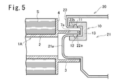
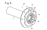
- FIG. 5 is a sectional view taken along the axis of the bobbin, showing a support structure for an end portion of the bobbin in FIG. It is a perspective view of a part of bobbin concerning a 3rd embodiment. It is a perspective view of a part of bobbin concerning a 4th embodiment.
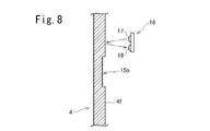
- FIG. 8 is a sectional view taken along line VIII-VIII in FIG. 7.
- 1 is a schematic configuration diagram of a thermal transfer printing apparatus according to an embodiment of the present invention.
- FIGS. 1 to 3 show a bobbin 1 according to the first embodiment.
- the bobbin 1 has a cylindrical spool portion 2 around which the thermal transfer sheet S is wound, and a cylindrical end portion provided coaxially with the spool portion 2 so as to be continuous with an axial end of the spool portion 2. 3, a flange 4 expanding from an end of the spool 2 (in this embodiment, a boundary between the spool 2 and the end 3), and from the flange 4 toward the side opposite to the spool 2. It has a projecting annular wall 5 and the like.
- the annular wall 5 has a short cylindrical shape, and stands upright coaxially with the end 3 from between the outer peripheral edge of the flange 4 and the end 3.
- a plurality of notches 6a and 6b are provided in the annular wall 5 as light-transmitting portions at intervals in the circumferential direction.
- the circumferential length of the notch 6a is larger than the circumferential length of the notch 6b.
- a sensor 10 is provided to detect the notches 6a and 6b.
- the sensor 10 includes a light emitting element 11 arranged on the outer peripheral side of the annular wall section 5, a light receiving element 12 arranged on the inner peripheral side of the annular wall section 5 so as to face the light emitting element 11, and a light receiving element 12 A substrate (not shown) having a circuit for converting a signal into a rectangular pulse signal and outputting the signal, a light emitting element 11, a light receiving element 12, a sensor base 13 for holding a circuit board, and the like are provided.
- the light emitting element 11 may be arranged on the inner peripheral side of the annular wall portion 5 and the light receiving element 12 may be arranged on the outer peripheral side.
- an L signal having a pulse-off width proportional to the pulse width is output.
- the type of the thermal transfer sheet ribbon is determined based on a combination of the signal, the H signal having a long pulse width, the L signal having a short pulse width, and the L signal having a long pulse width.
- the sensor output is set to H when the light receiving element 12 receives light, but may be set to L and H when no light is received. The same applies to the following embodiments.
- FIGS. 1 to 3 two types of notches 6a and 6b having different circumferential lengths are provided, but three or more types of notches having different circumferential lengths may be provided. Alternatively, only notches having the same circumferential length may be provided, and the distances between the notches may be different. Conversely, the circumferential lengths may be different, and the distance between the notches may be equal.
- the notch is provided in the annular wall 5, but an opening (hole) may be provided in the annular wall 5 instead of the notch.
- the shape of the notch or the opening is not particularly limited. Further, a transparent portion made of, for example, a transparent synthetic resin may be provided instead of the notch or the opening. The same applies to the following embodiments.
- a light transmitting portion may be provided on a portion other than the annular wall portion 5.
- Bobbins 1A and 1B according to one example are shown in FIGS.
- the annular wall portion 5 is omitted, and the end portion 3 is provided with openings 7a and 7b instead.
- the openings 7a and 7b are arranged in a line in the circumferential direction of the end portion 3.
- the circumferential length of the opening 7a is larger than the circumferential length of the opening 7b.
- the end of the bobbin 1A is supported by the bobbin support 21 of the thermal transfer printing apparatus 20.
- the sensor 10 is disposed on the bobbin support 21 of the thermal transfer printing apparatus 20.
- the bobbin support portion 21 is provided with openings (transparent portions) 22a and 22b through which light from the light emitting element 11 is transmitted.
- the boss 21a of the bobbin support 21 is inserted into the end 3 of the bobbin 1A, and the end 3 is slidably held by the boss 21a.
- An opening 22a is provided on the side peripheral surface of the boss 21a, and the light receiving element 12 is arranged in the boss 21a so as to face the opening 22a.
- the thermal transfer printing apparatus 20 is provided with an overhang 23 extending along the outer peripheral surface of the end portion 3, and an opening 22 b is provided at a portion of the overhang 23 facing the outer peripheral surface of the end portion 3. Have been.
- the light emitting element 11 is disposed in the overhanging portion 23 so as to face the opening 22b. Note that the light emitting element 11 may be arranged so as to face the opening 22a, and the light receiving element 12 may be arranged so as to face the opening 22b.
- the sub-flange 8 is provided on the end portion 3.
- a plurality of notches 9a and 9b are provided on the outer peripheral edge of the sub-flange 8 at intervals in the circumferential direction.
- the circumferential length of the cutout 9a is larger than the circumferential length of the cutout 9b.
- the sensor 10 is installed so that the light emitting element is arranged on one side and the light receiving element is arranged on the other side with the outer peripheral edge of the subflange 8 interposed therebetween.
- the diameter of the sub-flange 8 is slightly smaller than that of the flange portion 4.
- the type of the thermal transfer sheet ribbon can be determined based on the detection signal of the sensor 10 in the same manner as the bobbin 1.
- both the cutout portion and the opening or the transparent portion may be provided on the annular wall portion, the end portion, or the sub-flange.
- FIG. 7 is a perspective view of an end of a bobbin 1C according to the fourth embodiment.
- the annular wall portion 5 and the cutout portions 6a and 6b are omitted, and instead, the outer circumferential flange surface 4f of the flange 4 (the surface on the side opposite to the spool portion 2) is circumferentially spaced.
- a plurality of recesses 15a and 15b are provided at the center. Each of the recesses 15a and 15b is arranged at an equal radius from the axis of the bobbin 1C.
- the circumferential length of the recess 15a is larger than the circumferential length of the recess 15b.
- the bottom surfaces of the concave portions 15a and 15b are rough, and have low light reflectance.
- the flange surface 4f other than the concave portions 15a and 15b is a smooth surface and has a high light reflectance.
- a sensor 16 is provided facing the flange surface 4f at the same radius as the recesses 15a and 15b with respect to the axis of the bobbin 1C.
- the sensor 16 includes a light emitting element 17 and a light receiving element 18 and a circuit board (not shown). Light is projected from the light emitting element 17 toward the flange surface 4f, and the reflected light is received by the light receiving element 18.
- the amount of light received by the light receiving element 18 is large, and the output signal level of the sensor 16 becomes H.
- the concave portions 15a and 15b are rough surfaces and the other flange surfaces 4f are smooth surfaces.
- the concave portions 15a and 15b may be smooth surfaces and the other flange surfaces 4f may be rough surfaces.
- the rough surface portion may be provided without providing the concave portions 15a and 15b.
- a sub-flange portion may be provided, and the sub-flange portion may be provided with a rough surface portion and a smooth surface.
- the thickness of the annular wall portion 5 of the bobbin 1, the thickness of the end portion 3 of the bobbin 1A, and the thickness of the sub-flange 8 of the bobbin 1B are desirably about 1.5 mm or more and 3 mm or less. In this case, even if the molding color is not black, the light shielding property is sufficient, the strength is high, and the moldability of the mold is good.
- the depths of the notches 6a and 6b (dimensions in the direction parallel to the axis) and the depths of the notches 9a and 9b (dimensions of the sub-flanges 8 in the radial direction) are about 3 mm or more and 10 mm or less. In this case, the sensing by the sensor is sufficiently possible, and there is no problem in the strength of the molded product.
- the distance between the translucent parts is preferably about 2 mm or more and 15 mm or less. In this case, sensing by the sensor is sufficiently possible, and there is no problem of erroneous detection due to the strength of the molded product or adhesion of foreign matter. If the distance between the light-transmitting portions is reduced, several bits to several tens of bits of information can be provided per bobbin. When the information up to that point is not needed, the readability of the information can be improved by forming the shape repeatedly over the circumference. Although there is no problem with the fluctuation of the rotation speed during the operation of the ordinary DC motor, the reading error can be reduced with respect to the rotation unevenness by repeating the above data or arranging the ON / OFF data.
- information is separately read by an RFID, a contact tag, or the like, and the information of the two is collated to improve the reliability of data, damage to oblique light portions, and read errors. It may be provided.
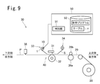
- FIG. 9 is a schematic configuration diagram of the thermal transfer printing apparatus 20 according to the embodiment of the present invention.
- the thermal transfer printing apparatus 30 includes a thermal head 31 that uses a thermal transfer sheet S, sublimates and transfers a yellow dye, a magenta dye, and a cyan dye onto an image receiving sheet 29 to print an image and forms a protective layer on the image. ing.
- a supply section 33 having a thermal transfer sheet ribbon formed by winding the thermal transfer sheet S around the bobbin 1 (or 1A to 1C) is provided downstream of the thermal head 31. Recovery of the thermal transfer sheet S upstream of the thermal head 31 is provided. A part 34 is provided. The thermal transfer sheet S fed out from the supply unit 33 passes through the thermal head 31 and is wound up by the collection unit 34 and collected.
- a rotatable platen roll 32 is provided at a position opposite to the thermal head 31 with the thermal transfer sheet S and the image receiving sheet 29 interposed therebetween.
- the printing section 40 including the thermal head 31 and the platen roll 32 sandwiches the thermal transfer sheet S and the image receiving sheet 29, heats the dye layer of the thermal transfer sheet S, and thermally transfers the dye onto the image receiving sheet 29 to form an image. .
- the printing unit 40 heats the protective layer forming area of the thermal transfer sheet S to transfer the protective layer 3 onto the image of the image receiving sheet 29.
- a capstan roller 39a which is rotatably driven to convey the image receiving sheet 29, and a pinch roller 39b which presses the image receiving sheet 29 to the capstan roller 39a.
- the image receiving sheet 29 is fed out from the image receiving sheet roll 20.
- a well-known image receiving sheet 29 can be used.
- the image receiving sheet 29 on which the image formation and the transfer of the protective layer have been performed in the printing unit 40 is cut out as a print sheet P by the cutter 38 on the downstream side.
- the print sheet P is discharged from a discharge port not shown.
- the signal from the sensor 10 (or 16) provided on the bobbin 1 of the supply unit 33 is taken into the control device 50.
- the control device 50 controls the driving of each part of the thermal transfer printing apparatus, and performs the discrimination processing of the thermal transfer sheet S and the printing processing.
- the control device 50 is a computer having a storage unit 52 including a CPU (Central Processing Unit), a flash memory, a ROM (Read-Only Memory), a RAM (Random Access Memory), and the like.
- the storage unit 52 stores the control program and the table T. When the CPU executes the control program, the type determination of the thermal transfer sheet S in the determination unit 51 is realized.
- the table T information read by the sensor 10 and the type of the thermal transfer sheet S are recorded in association with each other.
- the printing conditions printing speed, applied energy at the time of printing
- suitable for each type of the thermal transfer sheet S may be recorded in the table T.
- the determination unit 51 refers to the table T and determines the type of the thermal transfer sheet S loaded in the thermal transfer printing apparatus from the reading result of the sensor 10.
- the control device 50 controls the printing process based on the printing conditions according to the determined type of the thermal transfer sheet S.
- the controller 50 determines whether the type of the thermal transfer sheet S cannot be determined from the reading result of the sensor 10 or that the bobbin 1 does not have the cutout (or the opening or the rough surface), and the sensor 10 (or 16) When reading is not possible, a warning sound or a warning display may be output, or the printing process may be stopped.
- the thermal transfer sheet S is not limited to the one that transfers a dye, but may be one that transfers another color material such as a hot-melt ink.
- the thermal transfer sheet S may be an intermediate transfer medium in which a transfer layer is provided on one surface of a support.
- a first heating unit having a thermal head and a platen roll overlaps and heats an ink ribbon containing a yellow dye, a magenta dye, and a cyan dye with an intermediate transfer medium, and applies a color material to a transfer layer of the intermediate transfer medium. Transfer and print the image.
- a second heating unit having a heat roller and a pressure roll overlaps and heats the intermediate transfer medium and the transfer target, and transfers the transfer layer on which the image is formed to the transfer target.
- the image printing process and the transfer process of the transfer layer are controlled under conditions according to the determined type of the intermediate transfer medium.
- the present invention is not limited to the above-described embodiment as it is, and can be embodied by modifying its components in an implementation stage without departing from the scope of the invention.
- Various inventions can be formed by appropriately combining a plurality of constituent elements disclosed in the above embodiments. For example, some components may be deleted from all the components shown in the embodiment. Further, components of different embodiments may be appropriately combined.
Abstract
L'invention concerne une bobine et un ruban de feuille de transfert thermique qui permettent d'identifier le type de produit de celui-ci (type de produit, numéro de modèle de produit, etc.) dans un dispositif d'impression par transfert thermique. Une bobine (1) comprend une partie mandrin (2), une partie d'extrémité (3), une partie bride (4) et une partie de paroi annulaire (5). Des encoches (6a, 6b) sont ménagées dans le bord de la partie de paroi annulaire (5) à des intervalles donnés dans la direction circonférentielle. Les encoches (6a, 6b) ont des longueurs différentes dans la direction circonférentielle. La distance entre certaines des encoches diffère de la distance entre d'autres encoches. Un capteur (10) est disposé de manière à prendre en sandwich la partie de paroi annulaire (5) et comporte un élément émetteur de lumière (11) et un élément récepteur de lumière (12).
Applications Claiming Priority (2)
| Application Number | Priority Date | Filing Date | Title |
|---|---|---|---|
| JP2018-124440 | 2018-06-29 | ||
| JP2018124440A JP2020001324A (ja) | 2018-06-29 | 2018-06-29 | ボビン、熱転写シートリボン及び熱転写印画装置 |
Publications (1)
| Publication Number | Publication Date |
|---|---|
| WO2020003816A1 true WO2020003816A1 (fr) | 2020-01-02 |
Family
ID=68986387
Family Applications (1)
| Application Number | Title | Priority Date | Filing Date |
|---|---|---|---|
| PCT/JP2019/020116 WO2020003816A1 (fr) | 2018-06-29 | 2019-05-21 | Bobine, ruban de feuille de transfert thermique, et dispositif d'impression par transfert thermique |
Country Status (2)
| Country | Link |
|---|---|
| JP (1) | JP2020001324A (fr) |
| WO (1) | WO2020003816A1 (fr) |
Cited By (1)
| Publication number | Priority date | Publication date | Assignee | Title |
|---|---|---|---|---|
| USD982579S1 (en) | 2019-10-01 | 2023-04-04 | Microsoft Corporation | Computing device |
Citations (6)
| Publication number | Priority date | Publication date | Assignee | Title |
|---|---|---|---|---|
| JPH10114118A (ja) * | 1996-10-14 | 1998-05-06 | Sony Corp | ビデオプリンタのインクリボンユニット |
| JPH10258969A (ja) * | 1997-03-19 | 1998-09-29 | Dainippon Printing Co Ltd | ボビン |
| JP2005305936A (ja) * | 2004-04-23 | 2005-11-04 | Nidec Copal Corp | 中間転写型熱転写印刷装置 |
| JP2007308235A (ja) * | 2006-05-17 | 2007-11-29 | Shinko Electric Co Ltd | 画像形成装置 |
| JP2012045741A (ja) * | 2010-08-25 | 2012-03-08 | Toshiba Tec Corp | プリンタ及びロール体 |
| US20130129397A1 (en) * | 2011-11-23 | 2013-05-23 | Kai-Min Chu | Print system with ribbon identification function |
-
2018
- 2018-06-29 JP JP2018124440A patent/JP2020001324A/ja active Pending
-
2019
- 2019-05-21 WO PCT/JP2019/020116 patent/WO2020003816A1/fr active Application Filing
Patent Citations (6)
| Publication number | Priority date | Publication date | Assignee | Title |
|---|---|---|---|---|
| JPH10114118A (ja) * | 1996-10-14 | 1998-05-06 | Sony Corp | ビデオプリンタのインクリボンユニット |
| JPH10258969A (ja) * | 1997-03-19 | 1998-09-29 | Dainippon Printing Co Ltd | ボビン |
| JP2005305936A (ja) * | 2004-04-23 | 2005-11-04 | Nidec Copal Corp | 中間転写型熱転写印刷装置 |
| JP2007308235A (ja) * | 2006-05-17 | 2007-11-29 | Shinko Electric Co Ltd | 画像形成装置 |
| JP2012045741A (ja) * | 2010-08-25 | 2012-03-08 | Toshiba Tec Corp | プリンタ及びロール体 |
| US20130129397A1 (en) * | 2011-11-23 | 2013-05-23 | Kai-Min Chu | Print system with ribbon identification function |
Cited By (1)
| Publication number | Priority date | Publication date | Assignee | Title |
|---|---|---|---|---|
| USD982579S1 (en) | 2019-10-01 | 2023-04-04 | Microsoft Corporation | Computing device |
Also Published As
| Publication number | Publication date |
|---|---|
| JP2020001324A (ja) | 2020-01-09 |
Similar Documents
| Publication | Publication Date | Title |
|---|---|---|
| JP3097299B2 (ja) | インクリボンカセットの種別判別方法およびプリンタ | |
| KR100677578B1 (ko) | 열전사방식 화상형성장치 및 잉크리본잔량 표시/검출방법 | |
| EP1749674B1 (fr) | Appareil d'impression, dispositif et méthode de contrôle de movement de rubban encreur et programme | |
| JPH05221068A (ja) | インクリボン及び該インクリボンを用いるインクリボンカセット | |
| WO2020003816A1 (fr) | Bobine, ruban de feuille de transfert thermique, et dispositif d'impression par transfert thermique | |
| JP6040668B2 (ja) | 転写リボン巻取 | |
| US20060198682A1 (en) | Ribbon for printing apparatus, printing apparatus using this ribbon, and method for detecting ribbon type | |
| JP3580805B2 (ja) | 画像形成シートと画像形成方法及び画像形成装置 | |
| JP4884062B2 (ja) | プリンタのインクリボン判別装置 | |
| US6250826B1 (en) | Ink ribbon, cartridge containing ink ribbon, and method of discriminating failure location from ink ribbon base film | |
| KR100486060B1 (ko) | 색상식별마크를 구비한 잉크 리본, 이를 이용한 컬러 인쇄 방법 및 색상식별장치 | |
| JP2003211801A (ja) | インクリボン検出ユニット及びこれを用いたプリンタ装置 | |
| JP4515743B2 (ja) | 通帳類印刷装置及び通帳類印刷方法 | |
| JP2007069508A (ja) | インクシート及びインクシートカセット並びにプリンタ | |
| JP2000335034A (ja) | 穴コード読み取り装置 | |
| JP3901817B2 (ja) | プリンタ装置 | |
| US9120327B2 (en) | Tape drive and method of operating a tape drive | |
| JP2013169743A (ja) | ラベルプリンタ | |
| JP4606247B2 (ja) | プリンタ | |
| JPH05229239A (ja) | プリンタにおけるインクリボンカセットの使用量表示方法 | |
| JP2013176927A (ja) | 印刷装置 | |
| JPH0872372A (ja) | 印字装置及びそのインクリボン | |
| JP2021094831A (ja) | インクリボン及び画像形成装置 | |
| CN108357219A (zh) | 检测打印色带定向 | |
| JP2007008040A (ja) | カード用熱転写装置 |
Legal Events
| Date | Code | Title | Description |
|---|---|---|---|
| 121 | Ep: the epo has been informed by wipo that ep was designated in this application |
Ref document number: 19824503 Country of ref document: EP Kind code of ref document: A1 |
|
| NENP | Non-entry into the national phase |
Ref country code: DE |
|
| 122 | Ep: pct application non-entry in european phase |
Ref document number: 19824503 Country of ref document: EP Kind code of ref document: A1 |