WO2020003816A1 - Bobbin, thermal transfer sheet ribbon, and thermal transfer printing device - Google Patents
Bobbin, thermal transfer sheet ribbon, and thermal transfer printing device Download PDFInfo
- Publication number
- WO2020003816A1 WO2020003816A1 PCT/JP2019/020116 JP2019020116W WO2020003816A1 WO 2020003816 A1 WO2020003816 A1 WO 2020003816A1 JP 2019020116 W JP2019020116 W JP 2019020116W WO 2020003816 A1 WO2020003816 A1 WO 2020003816A1
- Authority
- WO
- WIPO (PCT)
- Prior art keywords
- bobbin
- thermal transfer
- transfer sheet
- light
- light reflectance
- Prior art date
Links
Images


Classifications
-
- B—PERFORMING OPERATIONS; TRANSPORTING
- B41—PRINTING; LINING MACHINES; TYPEWRITERS; STAMPS
- B41J—TYPEWRITERS; SELECTIVE PRINTING MECHANISMS, i.e. MECHANISMS PRINTING OTHERWISE THAN FROM A FORME; CORRECTION OF TYPOGRAPHICAL ERRORS
- B41J17/00—Mechanisms for manipulating page-width impression-transfer material, e.g. carbon paper
- B41J17/22—Supply arrangements for webs of impression-transfer material
- B41J17/24—Webs supplied from reels or spools attached to the machine
-
- B—PERFORMING OPERATIONS; TRANSPORTING
- B41—PRINTING; LINING MACHINES; TYPEWRITERS; STAMPS
- B41J—TYPEWRITERS; SELECTIVE PRINTING MECHANISMS, i.e. MECHANISMS PRINTING OTHERWISE THAN FROM A FORME; CORRECTION OF TYPOGRAPHICAL ERRORS
- B41J2/00—Typewriters or selective printing mechanisms characterised by the printing or marking process for which they are designed
- B41J2/315—Typewriters or selective printing mechanisms characterised by the printing or marking process for which they are designed characterised by selective application of heat to a heat sensitive printing or impression-transfer material
- B41J2/32—Typewriters or selective printing mechanisms characterised by the printing or marking process for which they are designed characterised by selective application of heat to a heat sensitive printing or impression-transfer material using thermal heads
- B41J2/325—Typewriters or selective printing mechanisms characterised by the printing or marking process for which they are designed characterised by selective application of heat to a heat sensitive printing or impression-transfer material using thermal heads by selective transfer of ink from ink carrier, e.g. from ink ribbon or sheet
-
- B—PERFORMING OPERATIONS; TRANSPORTING
- B41—PRINTING; LINING MACHINES; TYPEWRITERS; STAMPS
- B41J—TYPEWRITERS; SELECTIVE PRINTING MECHANISMS, i.e. MECHANISMS PRINTING OTHERWISE THAN FROM A FORME; CORRECTION OF TYPOGRAPHICAL ERRORS
- B41J2/00—Typewriters or selective printing mechanisms characterised by the printing or marking process for which they are designed
- B41J2/315—Typewriters or selective printing mechanisms characterised by the printing or marking process for which they are designed characterised by selective application of heat to a heat sensitive printing or impression-transfer material
- B41J2/32—Typewriters or selective printing mechanisms characterised by the printing or marking process for which they are designed characterised by selective application of heat to a heat sensitive printing or impression-transfer material using thermal heads
- B41J2/35—Typewriters or selective printing mechanisms characterised by the printing or marking process for which they are designed characterised by selective application of heat to a heat sensitive printing or impression-transfer material using thermal heads providing current or voltage to the thermal head
- B41J2/355—Control circuits for heating-element selection
- B41J2/36—Print density control
-
- B—PERFORMING OPERATIONS; TRANSPORTING
- B65—CONVEYING; PACKING; STORING; HANDLING THIN OR FILAMENTARY MATERIAL
- B65H—HANDLING THIN OR FILAMENTARY MATERIAL, e.g. SHEETS, WEBS, CABLES
- B65H7/00—Controlling article feeding, separating, pile-advancing, or associated apparatus, to take account of incorrect feeding, absence of articles, or presence of faulty articles
- B65H7/02—Controlling article feeding, separating, pile-advancing, or associated apparatus, to take account of incorrect feeding, absence of articles, or presence of faulty articles by feelers or detectors
- B65H7/14—Controlling article feeding, separating, pile-advancing, or associated apparatus, to take account of incorrect feeding, absence of articles, or presence of faulty articles by feelers or detectors by photoelectric feelers or detectors
-
- B—PERFORMING OPERATIONS; TRANSPORTING
- B65—CONVEYING; PACKING; STORING; HANDLING THIN OR FILAMENTARY MATERIAL
- B65H—HANDLING THIN OR FILAMENTARY MATERIAL, e.g. SHEETS, WEBS, CABLES
- B65H75/00—Storing webs, tapes, or filamentary material, e.g. on reels
- B65H75/02—Cores, formers, supports, or holders for coiled, wound, or folded material, e.g. reels, spindles, bobbins, cop tubes, cans, mandrels or chucks
- B65H75/18—Constructional details
Definitions
- the present invention relates to a bobbin around which a thermal transfer sheet is wound, a ribbon having the thermal transfer sheet wound around the bobbin, and a thermal transfer printing apparatus for performing a printing process by discriminating the thermal transfer sheet ribbon.
- a dye for sublimation transfer is used as a recording material, and this is transferred from a thermal transfer sheet (sublimation type thermal transfer sheet) having a dye layer in which a dye is supported on a base material such as a polyester film with an appropriate binder.
- a sublimation dye is thermally transferred onto an image receiving sheet having a dye receiving layer formed on a plastic film or the like, to form various full-color images.
- thermal transfer sheets have become diversified, and the use of these various types of thermal transfer sheets in one type of thermal transfer printing apparatus is increasing.
- Patent Document 1 discloses a configuration in which an IC tag storing unique information on a thermal transfer sheet is embedded in an IC tag holder on an end surface of a core around which the thermal transfer sheet is wound.
- Patent Literature 2 discloses a configuration in which an adapter is attached to an end of a core and a barcode or an IC tag is attached to an outer peripheral surface of the adapter.
- it is necessary to prepare parts such as an IC tag holder and an adapter and to assemble the parts with the core.
- IC tags are expensive and costly.
- Patent Document 3 describes that a two-dimensional code is provided on an outer peripheral surface of an end portion of a bobbin.
- the two-dimensional code is provided by attaching with an adhesive or printing directly on a bobbin (paragraph 0014). However, it takes time to bond and directly print the two-dimensional code.
- the present invention has been made in view of the above-described conventional situation, and has as its object to provide a bobbin and a thermal transfer sheet ribbon that can determine a product type (product type, product model number, etc.) with a thermal transfer printing apparatus. It is another object of the present invention to provide a thermal transfer printing apparatus that performs a printing process by determining a loaded thermal transfer sheet ribbon.
- the bobbin of the first aspect is a bobbin having a spool portion around which a thermal transfer sheet is wound and an identification portion of the thermal transfer sheet, wherein the identification portion allows a light to pass therethrough provided in a plurality in the circumferential direction of the bobbin. It has a light transmitting portion.
- the light transmitting portion is a cutout or an opening.
- the bobbin includes a flange portion expanding from an end of the spool portion, and an annular wall portion projecting from the flange portion on a side opposite to the spool portion.
- the light-transmitting portion is provided on the light-emitting device.
- the bobbin includes an end portion coaxial with the spool portion, the end portion being continuous with an end portion of the spool portion, and the light transmitting portion is provided at the end portion.
- the bobbin includes an end portion coaxial with the spool portion and connected to an end of the spool portion, and a sub-flange portion expanding from the end portion.
- An optical unit is provided.
- the circumferential length of some of the light transmitting portions is different from the circumferential length of the other light transmitting portions.
- the distance between some of the light transmitting portions is different from the distance between the other light transmitting portions.
- the bobbin of the eighth aspect is a bobbin having a spool portion around which a thermal transfer sheet is wound and an identification portion of the thermal transfer sheet, wherein a plurality of the identification portions are arranged in a circumferential direction of the bobbin, and have a low light reflectance. It has a low light reflectivity portion and a high light reflectivity portion having a higher light reflectivity than the low light reflectivity portion.
- the low light reflectivity portion is formed of a rough surface portion
- the high light reflectivity portion is formed of a smooth surface
- the bobbin includes a flange portion or a sub-flange portion, and the low light reflectivity portion and the high light reflectivity portion are provided on the flange portion or the sub flange portion.
- the circumferential length of some of the low light reflectivity portions is different from the circumferential length of the other low light reflectivity portions.
- the distance between some of the low light reflectance portions is different from the distance between the other low light reflectance portions.
- the thermal transfer sheet ribbon according to the thirteenth aspect includes the bobbin according to any one of the first to twelfth aspects, and a thermal transfer sheet wound around the spool of the bobbin.
- a thermal transfer printing apparatus has a thermal head and a platen roll, and superimposes a thermal transfer sheet drawn from the thermal transfer sheet ribbon of the thirteenth aspect and an image receiving sheet to form the thermal head and the platen roll.
- a thermal transfer printing apparatus that prints an image by transferring the coloring material by heating the thermal transfer sheet while the thermal head heats the thermal transfer sheet, and a sensor that reads the identification unit of the bobbin, and a reading result of the sensor. And a discriminating unit for discriminating the kind of the thermal transfer sheet from the above.
- a thermal transfer printing apparatus includes a thermal transfer sheet drawn from the thermal transfer sheet ribbon according to the thirteenth aspect and provided with a transfer layer on one surface of a support and an ink ribbon provided with a color material layer. Heating by superimposing, a first heating unit for transferring a color material to the transfer layer to print an image, and superimposing and heating the thermal transfer sheet and the transfer object on which the image is printed on the transfer layer;
- the apparatus further includes a second heating unit that transfers the transfer layer to the transfer target, a sensor that reads the identification unit of the bobbin, and a determination unit that determines a type of the thermal transfer sheet based on a result of reading the sensor.
- the printing process is performed under printing conditions according to the type of the thermal transfer sheet determined by the determination unit.
- the bobbin of the thermal transfer sheet ribbon is any of the bobbins of the first to seventh aspects, wherein the sensor comprises a light-emitting element that emits light toward the light-transmitting portion, and a light-emitting element that transmits light through the light-transmitting portion. And a light receiving element for receiving the light.
- the bobbin of the thermal transfer sheet ribbon is any of the bobbins of the eighth to twelfth aspects, wherein the sensor comprises: a light emitting element that emits light toward the low light reflectance portion or the high light reflectance portion; And a light receiving element for receiving light reflected from the low light reflectance portion or the high light reflectance portion.
- the type (product type, product model number, etc.) of the thermal transfer sheet can be determined by the thermal transfer printing apparatus.
- FIG. 2 is a perspective view of a part of the bobbin according to the first embodiment.
- FIG. 2 is a perspective view showing an arrangement of a sensor with respect to the bobbin of FIG. 1.
- FIG. 3 is a cross-sectional view of the bobbin in FIG. 2 in an axial center line direction. It is a perspective view of a part of bobbin concerning a 2nd embodiment.
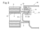
- FIG. 5 is a sectional view taken along the axis of the bobbin, showing a support structure for an end portion of the bobbin in FIG. It is a perspective view of a part of bobbin concerning a 3rd embodiment. It is a perspective view of a part of bobbin concerning a 4th embodiment.
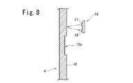
- FIG. 8 is a sectional view taken along line VIII-VIII in FIG. 7.
- 1 is a schematic configuration diagram of a thermal transfer printing apparatus according to an embodiment of the present invention.
- FIGS. 1 to 3 show a bobbin 1 according to the first embodiment.
- the bobbin 1 has a cylindrical spool portion 2 around which the thermal transfer sheet S is wound, and a cylindrical end portion provided coaxially with the spool portion 2 so as to be continuous with an axial end of the spool portion 2. 3, a flange 4 expanding from an end of the spool 2 (in this embodiment, a boundary between the spool 2 and the end 3), and from the flange 4 toward the side opposite to the spool 2. It has a projecting annular wall 5 and the like.
- the annular wall 5 has a short cylindrical shape, and stands upright coaxially with the end 3 from between the outer peripheral edge of the flange 4 and the end 3.
- a plurality of notches 6a and 6b are provided in the annular wall 5 as light-transmitting portions at intervals in the circumferential direction.
- the circumferential length of the notch 6a is larger than the circumferential length of the notch 6b.
- a sensor 10 is provided to detect the notches 6a and 6b.
- the sensor 10 includes a light emitting element 11 arranged on the outer peripheral side of the annular wall section 5, a light receiving element 12 arranged on the inner peripheral side of the annular wall section 5 so as to face the light emitting element 11, and a light receiving element 12 A substrate (not shown) having a circuit for converting a signal into a rectangular pulse signal and outputting the signal, a light emitting element 11, a light receiving element 12, a sensor base 13 for holding a circuit board, and the like are provided.
- the light emitting element 11 may be arranged on the inner peripheral side of the annular wall portion 5 and the light receiving element 12 may be arranged on the outer peripheral side.
- an L signal having a pulse-off width proportional to the pulse width is output.
- the type of the thermal transfer sheet ribbon is determined based on a combination of the signal, the H signal having a long pulse width, the L signal having a short pulse width, and the L signal having a long pulse width.
- the sensor output is set to H when the light receiving element 12 receives light, but may be set to L and H when no light is received. The same applies to the following embodiments.
- FIGS. 1 to 3 two types of notches 6a and 6b having different circumferential lengths are provided, but three or more types of notches having different circumferential lengths may be provided. Alternatively, only notches having the same circumferential length may be provided, and the distances between the notches may be different. Conversely, the circumferential lengths may be different, and the distance between the notches may be equal.
- the notch is provided in the annular wall 5, but an opening (hole) may be provided in the annular wall 5 instead of the notch.
- the shape of the notch or the opening is not particularly limited. Further, a transparent portion made of, for example, a transparent synthetic resin may be provided instead of the notch or the opening. The same applies to the following embodiments.
- a light transmitting portion may be provided on a portion other than the annular wall portion 5.
- Bobbins 1A and 1B according to one example are shown in FIGS.
- the annular wall portion 5 is omitted, and the end portion 3 is provided with openings 7a and 7b instead.
- the openings 7a and 7b are arranged in a line in the circumferential direction of the end portion 3.
- the circumferential length of the opening 7a is larger than the circumferential length of the opening 7b.
- the end of the bobbin 1A is supported by the bobbin support 21 of the thermal transfer printing apparatus 20.
- the sensor 10 is disposed on the bobbin support 21 of the thermal transfer printing apparatus 20.
- the bobbin support portion 21 is provided with openings (transparent portions) 22a and 22b through which light from the light emitting element 11 is transmitted.
- the boss 21a of the bobbin support 21 is inserted into the end 3 of the bobbin 1A, and the end 3 is slidably held by the boss 21a.
- An opening 22a is provided on the side peripheral surface of the boss 21a, and the light receiving element 12 is arranged in the boss 21a so as to face the opening 22a.
- the thermal transfer printing apparatus 20 is provided with an overhang 23 extending along the outer peripheral surface of the end portion 3, and an opening 22 b is provided at a portion of the overhang 23 facing the outer peripheral surface of the end portion 3. Have been.
- the light emitting element 11 is disposed in the overhanging portion 23 so as to face the opening 22b. Note that the light emitting element 11 may be arranged so as to face the opening 22a, and the light receiving element 12 may be arranged so as to face the opening 22b.
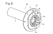
- the sub-flange 8 is provided on the end portion 3.
- a plurality of notches 9a and 9b are provided on the outer peripheral edge of the sub-flange 8 at intervals in the circumferential direction.
- the circumferential length of the cutout 9a is larger than the circumferential length of the cutout 9b.
- the sensor 10 is installed so that the light emitting element is arranged on one side and the light receiving element is arranged on the other side with the outer peripheral edge of the subflange 8 interposed therebetween.
- the diameter of the sub-flange 8 is slightly smaller than that of the flange portion 4.
- the type of the thermal transfer sheet ribbon can be determined based on the detection signal of the sensor 10 in the same manner as the bobbin 1.
- both the cutout portion and the opening or the transparent portion may be provided on the annular wall portion, the end portion, or the sub-flange.
- FIG. 7 is a perspective view of an end of a bobbin 1C according to the fourth embodiment.
- the annular wall portion 5 and the cutout portions 6a and 6b are omitted, and instead, the outer circumferential flange surface 4f of the flange 4 (the surface on the side opposite to the spool portion 2) is circumferentially spaced.
- a plurality of recesses 15a and 15b are provided at the center. Each of the recesses 15a and 15b is arranged at an equal radius from the axis of the bobbin 1C.
- the circumferential length of the recess 15a is larger than the circumferential length of the recess 15b.
- the bottom surfaces of the concave portions 15a and 15b are rough, and have low light reflectance.
- the flange surface 4f other than the concave portions 15a and 15b is a smooth surface and has a high light reflectance.
- a sensor 16 is provided facing the flange surface 4f at the same radius as the recesses 15a and 15b with respect to the axis of the bobbin 1C.
- the sensor 16 includes a light emitting element 17 and a light receiving element 18 and a circuit board (not shown). Light is projected from the light emitting element 17 toward the flange surface 4f, and the reflected light is received by the light receiving element 18.
- the amount of light received by the light receiving element 18 is large, and the output signal level of the sensor 16 becomes H.
- the concave portions 15a and 15b are rough surfaces and the other flange surfaces 4f are smooth surfaces.
- the concave portions 15a and 15b may be smooth surfaces and the other flange surfaces 4f may be rough surfaces.
- the rough surface portion may be provided without providing the concave portions 15a and 15b.
- a sub-flange portion may be provided, and the sub-flange portion may be provided with a rough surface portion and a smooth surface.
- the thickness of the annular wall portion 5 of the bobbin 1, the thickness of the end portion 3 of the bobbin 1A, and the thickness of the sub-flange 8 of the bobbin 1B are desirably about 1.5 mm or more and 3 mm or less. In this case, even if the molding color is not black, the light shielding property is sufficient, the strength is high, and the moldability of the mold is good.
- the depths of the notches 6a and 6b (dimensions in the direction parallel to the axis) and the depths of the notches 9a and 9b (dimensions of the sub-flanges 8 in the radial direction) are about 3 mm or more and 10 mm or less. In this case, the sensing by the sensor is sufficiently possible, and there is no problem in the strength of the molded product.
- the distance between the translucent parts is preferably about 2 mm or more and 15 mm or less. In this case, sensing by the sensor is sufficiently possible, and there is no problem of erroneous detection due to the strength of the molded product or adhesion of foreign matter. If the distance between the light-transmitting portions is reduced, several bits to several tens of bits of information can be provided per bobbin. When the information up to that point is not needed, the readability of the information can be improved by forming the shape repeatedly over the circumference. Although there is no problem with the fluctuation of the rotation speed during the operation of the ordinary DC motor, the reading error can be reduced with respect to the rotation unevenness by repeating the above data or arranging the ON / OFF data.
- information is separately read by an RFID, a contact tag, or the like, and the information of the two is collated to improve the reliability of data, damage to oblique light portions, and read errors. It may be provided.
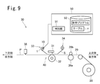
- FIG. 9 is a schematic configuration diagram of the thermal transfer printing apparatus 20 according to the embodiment of the present invention.
- the thermal transfer printing apparatus 30 includes a thermal head 31 that uses a thermal transfer sheet S, sublimates and transfers a yellow dye, a magenta dye, and a cyan dye onto an image receiving sheet 29 to print an image and forms a protective layer on the image. ing.
- a supply section 33 having a thermal transfer sheet ribbon formed by winding the thermal transfer sheet S around the bobbin 1 (or 1A to 1C) is provided downstream of the thermal head 31. Recovery of the thermal transfer sheet S upstream of the thermal head 31 is provided. A part 34 is provided. The thermal transfer sheet S fed out from the supply unit 33 passes through the thermal head 31 and is wound up by the collection unit 34 and collected.
- a rotatable platen roll 32 is provided at a position opposite to the thermal head 31 with the thermal transfer sheet S and the image receiving sheet 29 interposed therebetween.
- the printing section 40 including the thermal head 31 and the platen roll 32 sandwiches the thermal transfer sheet S and the image receiving sheet 29, heats the dye layer of the thermal transfer sheet S, and thermally transfers the dye onto the image receiving sheet 29 to form an image. .
- the printing unit 40 heats the protective layer forming area of the thermal transfer sheet S to transfer the protective layer 3 onto the image of the image receiving sheet 29.
- a capstan roller 39a which is rotatably driven to convey the image receiving sheet 29, and a pinch roller 39b which presses the image receiving sheet 29 to the capstan roller 39a.
- the image receiving sheet 29 is fed out from the image receiving sheet roll 20.
- a well-known image receiving sheet 29 can be used.
- the image receiving sheet 29 on which the image formation and the transfer of the protective layer have been performed in the printing unit 40 is cut out as a print sheet P by the cutter 38 on the downstream side.
- the print sheet P is discharged from a discharge port not shown.
- the signal from the sensor 10 (or 16) provided on the bobbin 1 of the supply unit 33 is taken into the control device 50.
- the control device 50 controls the driving of each part of the thermal transfer printing apparatus, and performs the discrimination processing of the thermal transfer sheet S and the printing processing.
- the control device 50 is a computer having a storage unit 52 including a CPU (Central Processing Unit), a flash memory, a ROM (Read-Only Memory), a RAM (Random Access Memory), and the like.
- the storage unit 52 stores the control program and the table T. When the CPU executes the control program, the type determination of the thermal transfer sheet S in the determination unit 51 is realized.
- the table T information read by the sensor 10 and the type of the thermal transfer sheet S are recorded in association with each other.
- the printing conditions printing speed, applied energy at the time of printing
- suitable for each type of the thermal transfer sheet S may be recorded in the table T.
- the determination unit 51 refers to the table T and determines the type of the thermal transfer sheet S loaded in the thermal transfer printing apparatus from the reading result of the sensor 10.
- the control device 50 controls the printing process based on the printing conditions according to the determined type of the thermal transfer sheet S.
- the controller 50 determines whether the type of the thermal transfer sheet S cannot be determined from the reading result of the sensor 10 or that the bobbin 1 does not have the cutout (or the opening or the rough surface), and the sensor 10 (or 16) When reading is not possible, a warning sound or a warning display may be output, or the printing process may be stopped.
- the thermal transfer sheet S is not limited to the one that transfers a dye, but may be one that transfers another color material such as a hot-melt ink.
- the thermal transfer sheet S may be an intermediate transfer medium in which a transfer layer is provided on one surface of a support.
- a first heating unit having a thermal head and a platen roll overlaps and heats an ink ribbon containing a yellow dye, a magenta dye, and a cyan dye with an intermediate transfer medium, and applies a color material to a transfer layer of the intermediate transfer medium. Transfer and print the image.
- a second heating unit having a heat roller and a pressure roll overlaps and heats the intermediate transfer medium and the transfer target, and transfers the transfer layer on which the image is formed to the transfer target.
- the image printing process and the transfer process of the transfer layer are controlled under conditions according to the determined type of the intermediate transfer medium.
- the present invention is not limited to the above-described embodiment as it is, and can be embodied by modifying its components in an implementation stage without departing from the scope of the invention.
- Various inventions can be formed by appropriately combining a plurality of constituent elements disclosed in the above embodiments. For example, some components may be deleted from all the components shown in the embodiment. Further, components of different embodiments may be appropriately combined.
Abstract
Provided are a bobbin and a thermal transfer sheet ribbon which make it possible to identify the product kind thereof (product type, product model number, etc.), in a thermal transfer printing device. A bobbin 1 has a spool part 2, an end part 3, a flange part 4, and an annular wall part 5. Notches 6a, 6b are provided in the edge of the annular wall part 5 at intervals in the circumferential direction. The notches 6a, 6b have different circumferential direction lengths. The distance between some of the notches differs from the distance between other notches. A sensor 10 is provided so as to sandwich the annular wall part 5 and has a light emitting element 11 and a light receiving element 12.
Description
本発明は、熱転写シートが巻回されるボビンと、このボビンに熱転写シートを巻回したリボンと、この熱転写シートリボンを判別して印画処理を行う熱転写印画装置に関する。
The present invention relates to a bobbin around which a thermal transfer sheet is wound, a ribbon having the thermal transfer sheet wound around the bobbin, and a thermal transfer printing apparatus for performing a printing process by discriminating the thermal transfer sheet ribbon.
熱転写印画装置にあっては、昇華転写用染料を記録材とし、これをポリエステルフィルム等の基材上に適当なバインダーで担持させた染料層を有する熱転写シート(昇華型熱転写シート)から、紙やプラスチックフィルム等に染料受容層を形成した受像シート上に昇華染料を熱転写し、各種のフルカラー画像を形成する。
In a thermal transfer printing apparatus, a dye for sublimation transfer is used as a recording material, and this is transferred from a thermal transfer sheet (sublimation type thermal transfer sheet) having a dye layer in which a dye is supported on a base material such as a polyester film with an appropriate binder. A sublimation dye is thermally transferred onto an image receiving sheet having a dye receiving layer formed on a plastic film or the like, to form various full-color images.
近年、熱転写記録技術の進歩により、熱転写シートは、その種類が多岐にわたるようになっており、これらの多種類の熱転写シートを一機種の熱転写印画装置で使用する場合が増えている。所望の印画性能や耐久性を得るために、熱転写シートの品種を判別し、品種に応じて熱転写シートの加熱エネルギーを制御する必要がある。
In recent years, with the progress of thermal transfer recording technology, the types of thermal transfer sheets have become diversified, and the use of these various types of thermal transfer sheets in one type of thermal transfer printing apparatus is increasing. In order to obtain desired printing performance and durability, it is necessary to determine the type of thermal transfer sheet and control the heating energy of the thermal transfer sheet according to the type.
特許文献1には、熱転写シートを巻き付けた巻芯の端面のICタグホルダに、熱転写シートに関する固有情報を記憶したICタグを埋設する構成が開示されている。特許文献2には、巻芯の端部にアダプタを取り付け、アダプタの外周面にバーコードやICタグを取り付ける構成が開示されている。しかし、ICタグホルダやアダプタ等の部品を準備し、巻芯に組み付ける作業が必要であった。また、ICタグは高価であり、コストがかかっていた。
Patent Document 1 discloses a configuration in which an IC tag storing unique information on a thermal transfer sheet is embedded in an IC tag holder on an end surface of a core around which the thermal transfer sheet is wound. Patent Literature 2 discloses a configuration in which an adapter is attached to an end of a core and a barcode or an IC tag is attached to an outer peripheral surface of the adapter. However, it is necessary to prepare parts such as an IC tag holder and an adapter and to assemble the parts with the core. Also, IC tags are expensive and costly.
特許文献3には、ボビンの端部外周面に2次元コードを設けることが記載されている。特許文献3では、2次元コードは、接着剤による張り付け、又はボビンに直接に印刷することにより設けられる(0014段落)。しかし、2次元コードの接着や直接の印刷には手間がかかる。
Patent Document 3 describes that a two-dimensional code is provided on an outer peripheral surface of an end portion of a bobbin. In Patent Literature 3, the two-dimensional code is provided by attaching with an adhesive or printing directly on a bobbin (paragraph 0014). However, it takes time to bond and directly print the two-dimensional code.
本発明は、上記従来の実状に鑑みてなされたものであり、熱転写印画装置で品種(製品種類、製品型番等)を判別可能とするボビン及び熱転写シートリボンを提供することを課題とする。また、本発明は、装填された熱転写シートリボンを判別して印画処理を行う熱転写印画装置を提供することを課題とする。
The present invention has been made in view of the above-described conventional situation, and has as its object to provide a bobbin and a thermal transfer sheet ribbon that can determine a product type (product type, product model number, etc.) with a thermal transfer printing apparatus. It is another object of the present invention to provide a thermal transfer printing apparatus that performs a printing process by determining a loaded thermal transfer sheet ribbon.
第1態様のボビンは、熱転写シートが巻回されるスプール部と、熱転写シートの識別部とを有するボビンにおいて、前記識別部は前記ボビンの周方向に複数個配設された、光を通過させる透光部を有する。
The bobbin of the first aspect is a bobbin having a spool portion around which a thermal transfer sheet is wound and an identification portion of the thermal transfer sheet, wherein the identification portion allows a light to pass therethrough provided in a plurality in the circumferential direction of the bobbin. It has a light transmitting portion.
第2態様のボビンでは、前記透光部は切欠部又は開口である。
In the bobbin according to the second aspect, the light transmitting portion is a cutout or an opening.
第3態様では、前記ボビンは、前記スプール部の端部から拡開するフランジ部と、このフランジ部からスプール部と反対側に突設された環状壁部とを備えており、この環状壁部に前記透光部が設けられている。
In a third aspect, the bobbin includes a flange portion expanding from an end of the spool portion, and an annular wall portion projecting from the flange portion on a side opposite to the spool portion. The light-transmitting portion is provided on the light-emitting device.
第4態様では、前記ボビンは、前記スプール部の端部に連なる、スプール部と同軸のエンド部を備えており、このエンド部に前記透光部が設けられている。
In the fourth aspect, the bobbin includes an end portion coaxial with the spool portion, the end portion being continuous with an end portion of the spool portion, and the light transmitting portion is provided at the end portion.
第5態様では、前記ボビンは、前記スプール部の端部に連なる、スプール部と同軸のエンド部と、このエンド部から拡開するサブフランジ部とを備えており、このサブフランジ部に前記透光部が設けられている。
In a fifth aspect, the bobbin includes an end portion coaxial with the spool portion and connected to an end of the spool portion, and a sub-flange portion expanding from the end portion. An optical unit is provided.
第6態様では、一部の前記透光部の周方向長さが他の透光部の周方向長さと異なる。
In the sixth aspect, the circumferential length of some of the light transmitting portions is different from the circumferential length of the other light transmitting portions.
第7態様では、一部の前記透光部同士の間の距離が他の透光部同士の間の距離と異なっている。
In the seventh aspect, the distance between some of the light transmitting portions is different from the distance between the other light transmitting portions.
第8態様のボビンは、熱転写シートが巻回されるスプール部と、熱転写シートの識別部を有するボビンにおいて、前記識別部は前記ボビンの周方向に複数個配設された、光反射率の低い低光反射率部と、この低光反射率部よりも光反射率が高い高光反射率部とを有する。
The bobbin of the eighth aspect is a bobbin having a spool portion around which a thermal transfer sheet is wound and an identification portion of the thermal transfer sheet, wherein a plurality of the identification portions are arranged in a circumferential direction of the bobbin, and have a low light reflectance. It has a low light reflectivity portion and a high light reflectivity portion having a higher light reflectivity than the low light reflectivity portion.
第9態様では、前記低光反射率部は粗面部よりなり、前記高光反射率部は平滑面よりなる。
In the ninth aspect, the low light reflectivity portion is formed of a rough surface portion, and the high light reflectivity portion is formed of a smooth surface.
第10態様では、前記ボビンは、フランジ部又はサブフランジ部を備えており、このフランジ部又はサブフランジ部に前記低光反射率部及び高光反射率部が設けられている。
In the tenth aspect, the bobbin includes a flange portion or a sub-flange portion, and the low light reflectivity portion and the high light reflectivity portion are provided on the flange portion or the sub flange portion.
第11態様では、一部の前記低光反射率部の周方向長さが他の低光反射率部の周方向長さと異なる。
In the eleventh aspect, the circumferential length of some of the low light reflectivity portions is different from the circumferential length of the other low light reflectivity portions.
第12態様では、一部の前記低光反射率部同士の間の距離が他の低光反射率部同士の間の距離と異なっている。
In the twelfth aspect, the distance between some of the low light reflectance portions is different from the distance between the other low light reflectance portions.
第13態様の熱転写シートリボンは、かかる第1~12態様のいずれかのボビンと、このボビンの前記スプール部に巻回された熱転写シートとを有する。
The thermal transfer sheet ribbon according to the thirteenth aspect includes the bobbin according to any one of the first to twelfth aspects, and a thermal transfer sheet wound around the spool of the bobbin.
第14態様の熱転写印画装置は、サーマルヘッド及びプラテンロールを有し、第13態様の熱転写シートリボンから引き出された熱転写シートと、受像シートとを重ね合わせて、前記サーマルヘッドと前記プラテンロールとの間を搬送させるとともに、前記サーマルヘッドが前記熱転写シートを加熱して色材を転写して画像を印画する熱転写印画装置であって、前記ボビンの前記識別部を読み取るセンサと、前記センサの読み取り結果から前記熱転写シートの品種を判別する判別部と、を備える。
A thermal transfer printing apparatus according to a fourteenth aspect has a thermal head and a platen roll, and superimposes a thermal transfer sheet drawn from the thermal transfer sheet ribbon of the thirteenth aspect and an image receiving sheet to form the thermal head and the platen roll. A thermal transfer printing apparatus that prints an image by transferring the coloring material by heating the thermal transfer sheet while the thermal head heats the thermal transfer sheet, and a sensor that reads the identification unit of the bobbin, and a reading result of the sensor. And a discriminating unit for discriminating the kind of the thermal transfer sheet from the above.
第15態様の熱転写印画装置は、第13態様の熱転写シートリボンから引き出された、支持体の一方の面上に転写層が設けられた熱転写シートと、色材層が設けられたインクリボンとを重ね合わせて加熱し、前記転写層に色材を転写して画像を印画する第1加熱部と、前記転写層に画像が印画された前記熱転写シートと被転写体とを重ね合わせて加熱し、前記転写層を前記被転写体に転写する第2加熱部と、前記ボビンの前記識別部を読み取るセンサと、前記センサの読み取り結果から前記熱転写シートの品種を判別する判別部と、を備える。
A thermal transfer printing apparatus according to a fifteenth aspect includes a thermal transfer sheet drawn from the thermal transfer sheet ribbon according to the thirteenth aspect and provided with a transfer layer on one surface of a support and an ink ribbon provided with a color material layer. Heating by superimposing, a first heating unit for transferring a color material to the transfer layer to print an image, and superimposing and heating the thermal transfer sheet and the transfer object on which the image is printed on the transfer layer; The apparatus further includes a second heating unit that transfers the transfer layer to the transfer target, a sensor that reads the identification unit of the bobbin, and a determination unit that determines a type of the thermal transfer sheet based on a result of reading the sensor.
第16態様では、前記判別部が判別した前記熱転写シートの品種に応じた印画条件で印画処理を行う。
In the sixteenth aspect, the printing process is performed under printing conditions according to the type of the thermal transfer sheet determined by the determination unit.
第17態様では、前記熱転写シートリボンのボビンは、第1~第7態様のいずれかのボビンであり、前記センサは、前記透光部に向って発光する発光素子と、該透光部を透過した光を受光する受光素子とを有する。
In a seventeenth aspect, the bobbin of the thermal transfer sheet ribbon is any of the bobbins of the first to seventh aspects, wherein the sensor comprises a light-emitting element that emits light toward the light-transmitting portion, and a light-emitting element that transmits light through the light-transmitting portion. And a light receiving element for receiving the light.
第18態様では、前記熱転写シートリボンのボビンは、第8~第12態様のいずれかのボビンであり、前記センサは、前記低光反射率部又は高光反射率部に向って発光する発光素子と、前記低光反射率部又は高光反射率部からの反射光を受光する受光素子とを有する。
In an eighteenth aspect, the bobbin of the thermal transfer sheet ribbon is any of the bobbins of the eighth to twelfth aspects, wherein the sensor comprises: a light emitting element that emits light toward the low light reflectance portion or the high light reflectance portion; And a light receiving element for receiving light reflected from the low light reflectance portion or the high light reflectance portion.
本発明によれば、熱転写印画装置で熱転写シートの品種(製品種類、製品型番等)を判別できる。
According to the present invention, the type (product type, product model number, etc.) of the thermal transfer sheet can be determined by the thermal transfer printing apparatus.
以下、図面を参照して実施の形態について説明する。
Hereinafter, embodiments will be described with reference to the drawings.
図1~3は第1の実施の形態に係るボビン1を示している。このボビン1は、熱転写シートSが巻回される円筒状のスプール部2と、スプール部2の軸心線方向の端部に連なるようにスプール部2と同軸に設けられた円筒状のエンド部3と、スプール部2の端部(この実施の形態では、スプール部2とエンド部3との境界部)から拡開するフランジ部4と、フランジ部4からスプール部2と反対側に向って突設された環状壁部5等を有する。この実施の形態では、環状壁部5は、短い円筒状であり、フランジ部4の外周縁とエンド部3との間からエンド部3と同軸に立設されている。
FIGS. 1 to 3 show a bobbin 1 according to the first embodiment. The bobbin 1 has a cylindrical spool portion 2 around which the thermal transfer sheet S is wound, and a cylindrical end portion provided coaxially with the spool portion 2 so as to be continuous with an axial end of the spool portion 2. 3, a flange 4 expanding from an end of the spool 2 (in this embodiment, a boundary between the spool 2 and the end 3), and from the flange 4 toward the side opposite to the spool 2. It has a projecting annular wall 5 and the like. In this embodiment, the annular wall 5 has a short cylindrical shape, and stands upright coaxially with the end 3 from between the outer peripheral edge of the flange 4 and the end 3.
この環状壁部5に、透光部として、周方向に間隔をおいて複数の切欠部6a,6bが設けられている。切欠部6aの周方向長さは、切欠部6bの周方向長さよりも大きい。
環状 A plurality of notches 6a and 6b are provided in the annular wall 5 as light-transmitting portions at intervals in the circumferential direction. The circumferential length of the notch 6a is larger than the circumferential length of the notch 6b.
図2,3の通り、この切欠部6a,6bを検出するようにセンサ10が設けられている。センサ10は、環状壁部5の外周側に配置された発光素子11と、環状壁部5の内周側において発光素子11に対峙するように配置された受光素子12と、受光素子12の受光信号を矩形パルス信号に変換して出力する回路を搭載した基板(図示略)と、これら発光素子11、受光素子12及び回路基板を保持するセンサベース13等を備えている。なお、発光素子11を環状壁部5の内周側に配置し、受光素子12を外周側に配置してもよい。
セ ン サ As shown in FIGS. 2 and 3, a sensor 10 is provided to detect the notches 6a and 6b. The sensor 10 includes a light emitting element 11 arranged on the outer peripheral side of the annular wall section 5, a light receiving element 12 arranged on the inner peripheral side of the annular wall section 5 so as to face the light emitting element 11, and a light receiving element 12 A substrate (not shown) having a circuit for converting a signal into a rectangular pulse signal and outputting the signal, a light emitting element 11, a light receiving element 12, a sensor base 13 for holding a circuit board, and the like are provided. In addition, the light emitting element 11 may be arranged on the inner peripheral side of the annular wall portion 5 and the light receiving element 12 may be arranged on the outer peripheral side.
ボビン1がその軸心回りに回転した場合、切欠部6a,6bが発光素子11と受光素子12との間を通過する際に、受光素子が発光素子11からの光を受光し、センサ10の出力がHとなり、切欠部6a,6b間の環状壁部5が発光素子11と受光素子12との間を通過する際に、センサ10の出力がLとなる。従って、ボビン1が回転する間に、切欠部6a,6bの周方向長さに比例したパルス幅(パルス・オンの幅)を有したH信号と、切欠部同士の間の距離(切欠部6a,6a間の距離、切欠部6b,6b間の距離、又は切欠部6a,6b間の距離)に比例したパルス・オフの幅を有したL信号とが出力されるので、パルス幅の短いH信号、パルス幅の長いH信号、パルス幅の短いL信号及びパルス幅の長いL信号の組み合わせに基づいて、熱転写シートリボンの品種が判別される。
When the bobbin 1 rotates around its axis, when the notches 6a and 6b pass between the light emitting element 11 and the light receiving element 12, the light receiving element receives light from the light emitting element 11 and the sensor 10 The output becomes H, and the output of the sensor 10 becomes L when the annular wall portion 5 between the notches 6a and 6b passes between the light emitting element 11 and the light receiving element 12. Therefore, while the bobbin 1 rotates, the H signal having a pulse width (pulse-on width) proportional to the circumferential length of the notches 6a and 6b and the distance between the notches ( notch 6a , 6a, the distance between the notches 6b, 6b, or the distance between the notches 6a, 6b), an L signal having a pulse-off width proportional to the pulse width is output. The type of the thermal transfer sheet ribbon is determined based on a combination of the signal, the H signal having a long pulse width, the L signal having a short pulse width, and the L signal having a long pulse width.
なお、上記説明では、受光素子12が受光した場合にセンサ出力がHになるものとしたが、逆にこれをLとし、非受光時にHとなるようにしてもよい。以下の各実施の形態においても同様である。
In the above description, the sensor output is set to H when the light receiving element 12 receives light, but may be set to L and H when no light is received. The same applies to the following embodiments.
図1~3では、周方向長さの異なる2種類の切欠部6a,6bを設けているが、周方向長さの異なる3種類以上の切欠部を設けてもよい。また、周方向長さの等しい切欠部のみを設け、切欠部同士の間の距離を異ならせるようにしてもよい。また、逆に周方向長さが異なり、切欠部同士の間の距離が等しくなるようにしてもよい。
In FIGS. 1 to 3, two types of notches 6a and 6b having different circumferential lengths are provided, but three or more types of notches having different circumferential lengths may be provided. Alternatively, only notches having the same circumferential length may be provided, and the distances between the notches may be different. Conversely, the circumferential lengths may be different, and the distance between the notches may be equal.
図1~3では、環状壁部5に切欠部を設けているが、切欠部の代りに開口(孔)を環状壁部5に設けてもよい。切欠部や開口の形状は特に限定されない。また、切欠部や開口の代りに、例えば透明な合成樹脂よりなる透明部を設けてもよい。以下の実施の形態においても同様である。
~ In FIGS. 1 to 3, the notch is provided in the annular wall 5, but an opening (hole) may be provided in the annular wall 5 instead of the notch. The shape of the notch or the opening is not particularly limited. Further, a transparent portion made of, for example, a transparent synthetic resin may be provided instead of the notch or the opening. The same applies to the following embodiments.
本発明では、環状壁部5以外の部分に透光部を設けてもよい。その一例に係るボビン1A,1Bを図4,5及び図6に示す。図4,5のボビン1Aでは、環状壁部5を省略し、代わりにエンド部3に開口7a,7bを設けている。開口7a,7bはエンド部3の周方向に一列に配列されている。開口7aの周方向長さは、開口7bの周方向長さよりも大きい。
In the present invention, a light transmitting portion may be provided on a portion other than the annular wall portion 5. Bobbins 1A and 1B according to one example are shown in FIGS. In the bobbin 1A shown in FIGS. 4 and 5, the annular wall portion 5 is omitted, and the end portion 3 is provided with openings 7a and 7b instead. The openings 7a and 7b are arranged in a line in the circumferential direction of the end portion 3. The circumferential length of the opening 7a is larger than the circumferential length of the opening 7b.
図5の通り、このボビン1Aの端部は、熱転写印画装置20のボビン支持部21に支持される。この実施の形態の場合、センサ10は、熱転写印画装置20のボビン支持部21に配置されている。ボビン支持部21には、発光素子11からの光を透過させる開口(透明部でもよい)22a,22bが設けられている。
の 通 り As shown in FIG. 5, the end of the bobbin 1A is supported by the bobbin support 21 of the thermal transfer printing apparatus 20. In the case of this embodiment, the sensor 10 is disposed on the bobbin support 21 of the thermal transfer printing apparatus 20. The bobbin support portion 21 is provided with openings (transparent portions) 22a and 22b through which light from the light emitting element 11 is transmitted.
図5の通り、ボビン1Aのエンド部3に対しボビン支持部21のボス部21aが挿入され、エンド部3がボス部21aに摺動回転自在に保持される。
As shown in FIG. 5, the boss 21a of the bobbin support 21 is inserted into the end 3 of the bobbin 1A, and the end 3 is slidably held by the boss 21a.
このボス部21aの側周面に開口22aが設けられており、受光素子12がこの開口22aに臨むようにしてボス部21a内に配置されている。熱転写印画装置20には、エンド部3の外周面に沿って張り出す張出部23が設けられており、この張出部23のうちエンド部3の外周面に対面する部分に開口22bが設けられている。発光素子11はこの開口22bに臨むようにして張出部23内に配置されている。なお、発光素子11が開口22aに臨むように配置され、受光素子12が開口22bに臨むように配置されてもよい。
An opening 22a is provided on the side peripheral surface of the boss 21a, and the light receiving element 12 is arranged in the boss 21a so as to face the opening 22a. The thermal transfer printing apparatus 20 is provided with an overhang 23 extending along the outer peripheral surface of the end portion 3, and an opening 22 b is provided at a portion of the overhang 23 facing the outer peripheral surface of the end portion 3. Have been. The light emitting element 11 is disposed in the overhanging portion 23 so as to face the opening 22b. Note that the light emitting element 11 may be arranged so as to face the opening 22a, and the light receiving element 12 may be arranged so as to face the opening 22b.
図6のボビン1Bでは、エンド部3にサブフランジ8が設けられている。このサブフランジ8の外周縁に、周方向に間隔をおいて複数個の切欠部9a,9bが設けられている。切欠部9aの周方向長さは切欠部9bの周方向長さよりも大きい。サブフランジ8の外周縁を挟んで一方の側に発光素子が配置され、他方の側に受光素子が配置されるようセンサ10が設置されている。
ボ In the bobbin 1B of FIG. 6, the sub-flange 8 is provided on the end portion 3. A plurality of notches 9a and 9b are provided on the outer peripheral edge of the sub-flange 8 at intervals in the circumferential direction. The circumferential length of the cutout 9a is larger than the circumferential length of the cutout 9b. The sensor 10 is installed so that the light emitting element is arranged on one side and the light receiving element is arranged on the other side with the outer peripheral edge of the subflange 8 interposed therebetween.
なお、この実施の形態では、サブフランジ8の直径をフランジ部4よりも若干小さくしている。このようにすることにより、サブフランジ8に他の物体が当ったりすることによるサブフランジ8の損傷を防止ないし抑制する効果が得られる。
In this embodiment, the diameter of the sub-flange 8 is slightly smaller than that of the flange portion 4. By doing so, the effect of preventing or suppressing damage to the sub-flange 8 due to another object hitting the sub-flange 8 can be obtained.
これらのボビン1A,1Bにおいても、ボビン1と同様にしてセンサ10の検出信号に基づいて熱転写シートリボンの品種を判別することができる。
も In these bobbins 1A and 1B, the type of the thermal transfer sheet ribbon can be determined based on the detection signal of the sensor 10 in the same manner as the bobbin 1.
上記各実施の形態では、透光部として切欠部のみ又は開口のみを設けるものとしているが、切欠部及び開口の双方あるいはさらに透明部を環状壁部やエンド部、サブフランジに設けてもよい。
In each of the above embodiments, only the cutout portion or only the opening is provided as the light-transmitting portion, but both the cutout portion and the opening or the transparent portion may be provided on the annular wall portion, the end portion, or the sub-flange.
図7は第4の実施の形態に係るボビン1Cの端部の斜視図である。
FIG. 7 is a perspective view of an end of a bobbin 1C according to the fourth embodiment.
このボビン1Cにあっては、環状壁部5及び切欠部6a,6bが省略され、代りに、フランジ4の外向きのフランジ面4f(スプール部2と反対側の面)に、周方向に間隔をおいて複数個の凹部15a,15bが設けられている。各凹部15a,15bは、ボビン1Cの軸心から等半径位に配置されている。凹部15aの周方向長さは、凹部15bの周方向長さよりも大きいものとなっている。この実施の形態では、凹部15a,15bの底面は粗面となっており、光反射率が低いものとなっている。凹部15a,15b以外のフランジ面4fは平滑面となっており、光反射率が高いものとなっている。
In the bobbin 1C, the annular wall portion 5 and the cutout portions 6a and 6b are omitted, and instead, the outer circumferential flange surface 4f of the flange 4 (the surface on the side opposite to the spool portion 2) is circumferentially spaced. A plurality of recesses 15a and 15b are provided at the center. Each of the recesses 15a and 15b is arranged at an equal radius from the axis of the bobbin 1C. The circumferential length of the recess 15a is larger than the circumferential length of the recess 15b. In this embodiment, the bottom surfaces of the concave portions 15a and 15b are rough, and have low light reflectance. The flange surface 4f other than the concave portions 15a and 15b is a smooth surface and has a high light reflectance.
図8に示すように、このフランジ面4fに対面して、ボビン1Cの軸心に対し凹部15a,15bと等半径位に、センサ16が設置されている。このセンサ16は、発光素子17及び受光素子18と、回路基板(図示略)とを備えている。発光素子17からフランジ面4fに向って光を投射し、反射光を受光素子18で受光する。光が凹部15a,15b以外の平滑面に照射されたときには、受光素子18の受光光量が多く、センサ16の出力信号レベルはHとなる。発光素子17からの光が凹部15a又は15bに照射されたときには、受光素子18の受光光量が少なく、センサ16の出力信号レベルはLとなる。従って、凹部15a,15bの周方向長さに比例したパルス・オフの幅のL信号が出力され、凹部15a又は15b同士の間の平滑面の周方向長さに比例したパルス・オン幅のH信号が出力される。従って、これらの組み合わせから熱転写シートリボンの品種を判別することができる。
セ ン サ As shown in FIG. 8, a sensor 16 is provided facing the flange surface 4f at the same radius as the recesses 15a and 15b with respect to the axis of the bobbin 1C. The sensor 16 includes a light emitting element 17 and a light receiving element 18 and a circuit board (not shown). Light is projected from the light emitting element 17 toward the flange surface 4f, and the reflected light is received by the light receiving element 18. When light is applied to a smooth surface other than the concave portions 15a and 15b, the amount of light received by the light receiving element 18 is large, and the output signal level of the sensor 16 becomes H. When the light from the light emitting element 17 irradiates the concave portion 15a or 15b, the amount of light received by the light receiving element 18 is small, and the output signal level of the sensor 16 becomes L. Therefore, an L signal having a pulse-off width proportional to the circumferential length of the concave portions 15a and 15b is output, and a pulse-on width H proportional to the circumferential length of the smooth surface between the concave portions 15a and 15b. A signal is output. Therefore, the type of the thermal transfer sheet ribbon can be determined from these combinations.
図7,8では、凹部15a,15bを粗面部とし、その他のフランジ面4fを平滑面としているが、逆に凹部15a,15bを平滑面とし、その他のフランジ面4fを粗面部としてもよい。また、凹部15a,15bを設けることなく粗面部を配置してもよい。なお、凹部15a,15bに粗面部を設けた場合、粗面部の摩耗が抑制される。
In FIGS. 7 and 8, the concave portions 15a and 15b are rough surfaces and the other flange surfaces 4f are smooth surfaces. However, the concave portions 15a and 15b may be smooth surfaces and the other flange surfaces 4f may be rough surfaces. Further, the rough surface portion may be provided without providing the concave portions 15a and 15b. When the concave portions 15a and 15b are provided with a rough surface portion, wear of the rough surface portions is suppressed.
なお、サブフランジ部を設け、このサブフランジ部に粗面部と平滑面とを設けてもよい。
Note that a sub-flange portion may be provided, and the sub-flange portion may be provided with a rough surface portion and a smooth surface.
本発明を特に限定するものではないが、ボビン1の環状壁部5の厚み、ボビン1Aのエンド部3の厚み、ボビン1Bのサブフランジ8の厚みは、1.5mm以上3mm以下程度が望ましい。これであれば、成形色が黒でなくても遮光性が十分であり、また、強度が高く、モールドの成形性も良好である。
な い Although the present invention is not particularly limited, the thickness of the annular wall portion 5 of the bobbin 1, the thickness of the end portion 3 of the bobbin 1A, and the thickness of the sub-flange 8 of the bobbin 1B are desirably about 1.5 mm or more and 3 mm or less. In this case, even if the molding color is not black, the light shielding property is sufficient, the strength is high, and the moldability of the mold is good.
切欠部6a,6bの深さ(軸心線と平行方向の寸法)及び切欠部9a,9bの深さ(サブフランジ8の半径方向の寸法)は、3mm以上10mm以下程度が望ましい。これであれば、センサの感知が充分可能であるし、成形品の強度も問題ない。
深 It is desirable that the depths of the notches 6a and 6b (dimensions in the direction parallel to the axis) and the depths of the notches 9a and 9b (dimensions of the sub-flanges 8 in the radial direction) are about 3 mm or more and 10 mm or less. In this case, the sensing by the sensor is sufficiently possible, and there is no problem in the strength of the molded product.
透光部同士の間の距離は、2mm以上15mm以下程度が望ましい。これであれば、センサの感知が充分可能であるし、成形品の強度や異物付着による誤検知なども問題ない。なお、透光部間の距離を小さくすればボビン1本当たり、数ビット~数十ビットの情報をもたせることができる。そこまでの情報がいらない場合は、周長にわたって繰り返し形状にすることで、情報の読み取り性を高めることができる。通常のDCモーターの駆動程度の動作時の回転速度の変動には問題がないが、上記のデータの繰り返しやON/OFFデータの並べ方などで回転ムラに対して読み取りエラーを削減できる。
距離 The distance between the translucent parts is preferably about 2 mm or more and 15 mm or less. In this case, sensing by the sensor is sufficiently possible, and there is no problem of erroneous detection due to the strength of the molded product or adhesion of foreign matter. If the distance between the light-transmitting portions is reduced, several bits to several tens of bits of information can be provided per bobbin. When the information up to that point is not needed, the readability of the information can be improved by forming the shape repeatedly over the circumference. Although there is no problem with the fluctuation of the rotation speed during the operation of the ordinary DC motor, the reading error can be reduced with respect to the rotation unevenness by repeating the above data or arranging the ON / OFF data.
本発明では、センサ10,16による情報読み取りとは別に、RFID、接触式タグなどで情報を別途読み取り、両者の情報を照合することで、データの確実性向上や斜光部分の破損、読み取りエラーに備えるようにしてもよい。
In the present invention, in addition to the information reading by the sensors 10 and 16, information is separately read by an RFID, a contact tag, or the like, and the information of the two is collated to improve the reliability of data, damage to oblique light portions, and read errors. It may be provided.
図9は、本発明の実施の形態に係る熱転写印画装置20の概略構成図である。この熱転写印画装置30は、熱転写シートSを用いて、受像シート29上にイエロー染料、マゼンタ染料、シアン染料を昇華転写させて画像を印画し、画像上に保護層を形成するサーマルヘッド31を備えている。
FIG. 9 is a schematic configuration diagram of the thermal transfer printing apparatus 20 according to the embodiment of the present invention. The thermal transfer printing apparatus 30 includes a thermal head 31 that uses a thermal transfer sheet S, sublimates and transfers a yellow dye, a magenta dye, and a cyan dye onto an image receiving sheet 29 to print an image and forms a protective layer on the image. ing.
サーマルヘッド31の下流側に、熱転写シートSをボビン1(又は1A~1C)に巻き付けて形成された熱転写シートリボンを有する供給部33が設けられ、サーマルヘッド31の上流側に熱転写シートSの回収部34が設けられている。供給部33から繰り出された熱転写シートSは、サーマルヘッド31を通って、回収部34に巻き取られて回収されるようになっている。
A supply section 33 having a thermal transfer sheet ribbon formed by winding the thermal transfer sheet S around the bobbin 1 (or 1A to 1C) is provided downstream of the thermal head 31. Recovery of the thermal transfer sheet S upstream of the thermal head 31 is provided. A part 34 is provided. The thermal transfer sheet S fed out from the supply unit 33 passes through the thermal head 31 and is wound up by the collection unit 34 and collected.
熱転写シートS及び受像シート29を挟んでサーマルヘッド31とは反対側の位置に、回転自在なプラテンロール32が設けられている。サーマルヘッド31及びプラテンロール32を含む印画部40は、熱転写シートS及び受像シート29を挟み込み、熱転写シートSの染料層を加熱して、受像シート29上に染料を熱転写することで画像を形成する。
A rotatable platen roll 32 is provided at a position opposite to the thermal head 31 with the thermal transfer sheet S and the image receiving sheet 29 interposed therebetween. The printing section 40 including the thermal head 31 and the platen roll 32 sandwiches the thermal transfer sheet S and the image receiving sheet 29, heats the dye layer of the thermal transfer sheet S, and thermally transfers the dye onto the image receiving sheet 29 to form an image. .
また、印画部40は、熱転写シートSの保護層形成領域を加熱して、受像シート29の画像上に保護層3を転写する。
(4) The printing unit 40 heats the protective layer forming area of the thermal transfer sheet S to transfer the protective layer 3 onto the image of the image receiving sheet 29.
サーマルヘッド31の上流側には、受像シート29の搬送を行うための回転駆動自在なキャプスタンローラ39aと、キャプスタンローラ39aに受像シート29を圧着させるためのピンチローラ39bが設けられている。
(4) On the upstream side of the thermal head 31, there are provided a capstan roller 39a which is rotatably driven to convey the image receiving sheet 29, and a pinch roller 39b which presses the image receiving sheet 29 to the capstan roller 39a.
受像シート29は、受像シートロール20から繰り出される。受像シート29には公知のものを使用できる。
像 The image receiving sheet 29 is fed out from the image receiving sheet roll 20. A well-known image receiving sheet 29 can be used.
印画部40で画像形成及び保護層の転写が施された受像シート29は、下流側でカッター38によりプリント枚葉Pとして切り出される。プリント枚葉Pは、図示を省略する排出口から排出される。
The image receiving sheet 29 on which the image formation and the transfer of the protective layer have been performed in the printing unit 40 is cut out as a print sheet P by the cutter 38 on the downstream side. The print sheet P is discharged from a discharge port not shown.
供給部33のボビン1に設けられたセンサ10(又は16)からの信号が制御装置50に取り込まれる。
The signal from the sensor 10 (or 16) provided on the bobbin 1 of the supply unit 33 is taken into the control device 50.
制御装置50は、熱転写印画装置の各部の駆動を制御し、熱転写シートSの判別処理や、印画処理を行う。制御装置50は、CPU(中央演算処理装置)や、フラッシュメモリ、ROM(Read-only Memory)、RAM(Random Access Memory)等からなる記憶部52を有したコンピュータである。記憶部52は、制御プログラム及びテーブルTを格納する。CPUが制御プログラムを実行することで、判別部51での熱転写シートSの品種判別が実現される。
The control device 50 controls the driving of each part of the thermal transfer printing apparatus, and performs the discrimination processing of the thermal transfer sheet S and the printing processing. The control device 50 is a computer having a storage unit 52 including a CPU (Central Processing Unit), a flash memory, a ROM (Read-Only Memory), a RAM (Random Access Memory), and the like. The storage unit 52 stores the control program and the table T. When the CPU executes the control program, the type determination of the thermal transfer sheet S in the determination unit 51 is realized.
テーブルTには、センサ10で読み取られる情報と、熱転写シートSの品種とが対応付けて記録されている。テーブルTに、熱転写シートSの品種毎に好適な印画条件(印画速度、印画時の印加エネルギー)が記録されていてもよい。
In the table T, information read by the sensor 10 and the type of the thermal transfer sheet S are recorded in association with each other. The printing conditions (printing speed, applied energy at the time of printing) suitable for each type of the thermal transfer sheet S may be recorded in the table T.
判別部51は、テーブルTを参照し、センサ10の読み取り結果から、熱転写印画装置に装填されている熱転写シートSの品種を判別する。
The determination unit 51 refers to the table T and determines the type of the thermal transfer sheet S loaded in the thermal transfer printing apparatus from the reading result of the sensor 10.
制御装置50は、判別した熱転写シートSの品種に応じた印画条件に基づいて、印画処理を制御する。制御装置50は、センサ10の読み取り結果から熱転写シートSの品種が判別できない場合や、ボビン1に切欠部(又は開口、粗面部)が設けられておらず、センサ10(又は16)が情報を読み取れない場合に、警告音や警告表示を出力したり、印画処理を中止したりしてもよい。
The control device 50 controls the printing process based on the printing conditions according to the determined type of the thermal transfer sheet S. The controller 50 determines whether the type of the thermal transfer sheet S cannot be determined from the reading result of the sensor 10 or that the bobbin 1 does not have the cutout (or the opening or the rough surface), and the sensor 10 (or 16) When reading is not possible, a warning sound or a warning display may be output, or the printing process may be stopped.
熱転写シートSは、染料を転写するものに限定されず、熱溶融性インキ等の他の色材を転写するものでもよい。
The thermal transfer sheet S is not limited to the one that transfers a dye, but may be one that transfers another color material such as a hot-melt ink.
また、熱転写シートSは、支持体の一方の面上に転写層が設けられた中間転写媒体でもよい。例えば、サーマルヘッド及びプラテンロールを有する第1加熱部が、イエロー染料、マゼンタ染料、シアン染料を含むインクリボンと中間転写媒体とを重ね合わせて加熱して、中間転写媒体の転写層に色材を転写して画像を印画する。その後、ヒートローラ及び加圧ロールを有する第2加熱部が、中間転写媒体と被転写体と重ね合わせて加熱し、画像が形成された転写層を被転写体に転写する。判別した中間転写媒体の品種に応じた条件で画像印画処理や転写層の転写処理を制御する。
The thermal transfer sheet S may be an intermediate transfer medium in which a transfer layer is provided on one surface of a support. For example, a first heating unit having a thermal head and a platen roll overlaps and heats an ink ribbon containing a yellow dye, a magenta dye, and a cyan dye with an intermediate transfer medium, and applies a color material to a transfer layer of the intermediate transfer medium. Transfer and print the image. Thereafter, a second heating unit having a heat roller and a pressure roll overlaps and heats the intermediate transfer medium and the transfer target, and transfers the transfer layer on which the image is formed to the transfer target. The image printing process and the transfer process of the transfer layer are controlled under conditions according to the determined type of the intermediate transfer medium.
なお、本発明は上記実施形態そのままに限定されるものではなく、実施段階ではその要旨を逸脱しない範囲で構成要素を変形して具体化できる。また、上記実施形態に開示されている複数の構成要素の適宜な組み合わせにより、種々の発明を形成できる。例えば、実施形態に示される全構成要素から幾つかの構成要素を削除してもよい。さらに、異なる実施形態にわたる構成要素を適宜組み合わせてもよい。
Note that the present invention is not limited to the above-described embodiment as it is, and can be embodied by modifying its components in an implementation stage without departing from the scope of the invention. Various inventions can be formed by appropriately combining a plurality of constituent elements disclosed in the above embodiments. For example, some components may be deleted from all the components shown in the embodiment. Further, components of different embodiments may be appropriately combined.
本発明を特定の態様を用いて詳細に説明したが、本発明の意図と範囲を離れることなく様々な変更が可能であることは当業者に明らかである。
本出願は、2018年6月29日付で出願された日本特許出願2018-124440に基づいており、その全体が引用により援用される。 Although the present invention has been described in detail with particular embodiments, it will be apparent to those skilled in the art that various modifications can be made without departing from the spirit and scope of the invention.
This application is based on Japanese Patent Application No. 2018-124440 filed on June 29, 2018, which is incorporated by reference in its entirety.
1,1A~1C ボビン
2 スプール部
3 エンド部
4 フランジ部
5 環状壁部
6a,6b,9a,9b 切欠部
7a,7b 開口
10,16 センサ
15a,15b 凹部
20 熱転写印画装置
21 ボビン支持部
29 受像シート
30 熱転写印画装置
31 サーマルヘッド
40 印画部
50 制御装置 1, 1A to1C bobbin 2 spool part 3 end part 4 flange part 5 annular wall part 6a, 6b, 9a, 9b cutout part 7a, 7b opening 10, 16 sensor 15a, 15b concave part 20 thermal transfer printing device 21 bobbin support unit 29 image receiving Sheet 30 Thermal transfer printing device 31 Thermal head 40 Printing unit 50 Control device
2 スプール部
3 エンド部
4 フランジ部
5 環状壁部
6a,6b,9a,9b 切欠部
7a,7b 開口
10,16 センサ
15a,15b 凹部
20 熱転写印画装置
21 ボビン支持部
29 受像シート
30 熱転写印画装置
31 サーマルヘッド
40 印画部
50 制御装置 1, 1A to
Claims (18)
- 熱転写シートが巻回されるスプール部と、熱転写シートの識別部とを有するボビンにおいて、
前記識別部は前記ボビンの周方向に複数個配設された、光を通過させる透光部を有することを特徴とするボビン。 In a bobbin having a spool portion around which the thermal transfer sheet is wound and an identification portion of the thermal transfer sheet,
The bobbin according to claim 2, wherein the identification unit includes a plurality of light transmitting units that are arranged in a circumferential direction of the bobbin and allow light to pass through. - 前記透光部は切欠部又は開口であることを特徴とする請求項1に記載のボビン。 The bobbin according to claim 1, wherein the translucent portion is a cutout or an opening.
- 前記ボビンは、前記スプール部の端部から拡開するフランジ部と、このフランジ部からスプール部と反対側に突設された環状壁部とを備えており、
この環状壁部に前記透光部が設けられていることを特徴とする請求項1又は2に記載のボビン。 The bobbin includes a flange portion expanding from an end of the spool portion, and an annular wall portion protruding from the flange portion on a side opposite to the spool portion,
The bobbin according to claim 1, wherein the light-transmitting portion is provided on the annular wall portion. - 前記ボビンは、前記スプール部の端部に連なる、スプール部と同軸のエンド部を備えており、
このエンド部に前記透光部が設けられていることを特徴とする請求項1又は2に記載のボビン。 The bobbin has an end portion coaxial with the spool portion, which is connected to an end portion of the spool portion,
The bobbin according to claim 1, wherein the light transmitting portion is provided at the end portion. - 前記ボビンは、前記スプール部の端部に連なる、スプール部と同軸のエンド部と、このエンド部から拡開するサブフランジ部とを備えており、
このサブフランジ部に前記透光部が設けられていることを特徴とする請求項1に記載のボビン。 The bobbin includes an end portion coaxial with the spool portion, which is continuous with an end portion of the spool portion, and a sub-flange portion expanding from the end portion,
The bobbin according to claim 1, wherein the translucent portion is provided on the sub-flange portion. - 一部の前記透光部の周方向長さが他の透光部の周方向長さと異なることを特徴とする請求項1乃至5のいずれか1項に記載のボビン。 The bobbin according to any one of claims 1 to 5, wherein a circumferential length of some of the light transmitting portions is different from a circumferential length of another light transmitting portion.
- 一部の前記透光部同士の間の距離が他の透光部同士の間の距離と異なることを特徴とする請求項1乃至6のいずれか1項に記載のボビン。 The bobbin according to any one of claims 1 to 6, wherein a distance between some of the light transmitting portions is different from a distance between other light transmitting portions.
- 熱転写シートが巻回されるスプール部と、熱転写シートの識別部を有するボビンにおいて、
前記識別部は前記ボビンの周方向に複数個配設された、光反射率の低い低光反射率部と、この低光反射率部よりも光反射率が高い高光反射率部とを有することを特徴とするボビン。 In a spool portion around which the thermal transfer sheet is wound, and a bobbin having an identification portion for the thermal transfer sheet,
The identification unit includes a plurality of low light reflectance portions having a low light reflectance and a high light reflectance portion having a higher light reflectance than the low light reflectance portion, which are disposed in a plurality in the circumferential direction of the bobbin. A bobbin. - 前記低光反射率部は粗面部よりなり、前記高光反射率部は平滑面よりなることを特徴とする請求項8に記載のボビン。 The bobbin according to claim 8, wherein the low light reflectivity portion comprises a rough surface portion, and the high light reflectivity portion comprises a smooth surface.
- 前記ボビンは、フランジ部又はサブフランジ部を備えており、
このフランジ部又はサブフランジ部に前記低光反射率部及び高光反射率部が設けられていることを特徴とする請求項8又は9に記載のボビン。 The bobbin has a flange portion or a sub-flange portion,
The bobbin according to claim 8 or 9, wherein the low light reflectance portion and the high light reflectance portion are provided on the flange portion or the sub-flange portion. - 一部の前記低光反射率部の周方向長さが他の低光反射率部の周方向長さと異なることを特徴とする請求項10に記載のボビン。 The bobbin according to claim 10, wherein the circumferential length of some of the low light reflectance portions is different from the circumferential length of the other low light reflectance portions.
- 一部の前記低光反射率部同士の間の距離が他の低光反射率部同士の間の距離と異なっていることを特徴とする請求項11に記載のボビン。 The bobbin according to claim 11, wherein a distance between some of the low light reflectance portions is different from a distance between other low light reflectance portions.
- 請求項1乃至12のいずれか1項に記載のボビンと、このボビンの前記スプール部に巻回された熱転写シートとを有する熱転写シートリボン。 A thermal transfer sheet ribbon comprising the bobbin according to any one of claims 1 to 12, and a thermal transfer sheet wound around the spool portion of the bobbin.
- サーマルヘッド及びプラテンロールを有し、
請求項13に記載の熱転写シートリボンから引き出された熱転写シートと、受像シートとを重ね合わせて、前記サーマルヘッドと前記プラテンロールとの間を搬送させるとともに、前記サーマルヘッドが前記熱転写シートを加熱して色材を転写して画像を印画する熱転写印画装置であって、
前記ボビンの前記識別部を読み取るセンサと、
前記センサの読み取り結果から前記熱転写シートの品種を判別する判別部と、
を備える熱転写印画装置。 Having a thermal head and a platen roll,
A thermal transfer sheet drawn from the thermal transfer sheet ribbon according to claim 13 and an image receiving sheet are superimposed on each other, and conveyed between the thermal head and the platen roll, and the thermal head heats the thermal transfer sheet. A thermal transfer printing apparatus for transferring a color material to print an image,
A sensor for reading the identification unit of the bobbin;
A determination unit configured to determine a type of the thermal transfer sheet from a reading result of the sensor;
A thermal transfer printing apparatus comprising: - 請求項13に記載の熱転写シートリボンから引き出された、支持体の一方の面上に転写層が設けられた熱転写シートと、色材層が設けられたインクリボンとを重ね合わせて加熱し、前記転写層に色材を転写して画像を印画する第1加熱部と、
前記転写層に画像が印画された前記熱転写シートと被転写体とを重ね合わせて加熱し、前記転写層を前記被転写体に転写する第2加熱部と、
前記ボビンの前記識別部を読み取るセンサと、
前記センサの読み取り結果から前記熱転写シートの品種を判別する判別部と、
を備える熱転写印画装置。 A heat transfer sheet drawn from the heat transfer sheet ribbon according to claim 13, wherein a heat transfer sheet provided with a transfer layer on one surface of a support and an ink ribbon provided with a color material layer are superposed and heated, and A first heating unit that transfers a color material to a transfer layer and prints an image;
A second heating unit that superimposes and heats the thermal transfer sheet having the image printed on the transfer layer and the object to be transferred, and transfers the transfer layer to the object to be transferred;
A sensor for reading the identification unit of the bobbin;
A determination unit configured to determine a type of the thermal transfer sheet from a reading result of the sensor;
A thermal transfer printing apparatus comprising: - 前記判別部が判別した前記熱転写シートの品種に応じた印画条件で印画処理を行うことを特徴とする請求項14又は15に記載の熱転写印画装置。 16. The thermal transfer printing apparatus according to claim 14, wherein the printing process is performed under printing conditions according to a type of the thermal transfer sheet determined by the determination unit.
- 前記熱転写シートリボンのボビンは、請求項1乃至7のいずれか1項に記載のボビンであり、
前記センサは、前記透光部に向って発光する発光素子と、前記透光部を透過した光を受光する受光素子とを有することを特徴とする請求項14乃至16のいずれか1項に記載の熱転写印画装置。 The bobbin of the thermal transfer sheet ribbon is the bobbin according to any one of claims 1 to 7,
17. The sensor according to claim 14, wherein the sensor has a light emitting element that emits light toward the light transmitting part and a light receiving element that receives light transmitted through the light transmitting part. Thermal transfer printing equipment. - 前記熱転写シートリボンのボビンは、請求項8乃至12のいずれか1項に記載のボビンであり、
前記センサは、前記低光反射率部又は高光反射率部に向って発光する発光素子と、前記低光反射率部又は高光反射率部からの反射光を受光する受光素子とを有することを特徴とする請求項14乃至16のいずれか1項に記載の熱転写印画装置。 The bobbin of the thermal transfer sheet ribbon is the bobbin according to any one of claims 8 to 12,
The sensor includes a light emitting element that emits light toward the low light reflectance section or the high light reflectance section, and a light receiving element that receives light reflected from the low light reflectance section or the high light reflectance section. The thermal transfer printing apparatus according to any one of claims 14 to 16, wherein
Applications Claiming Priority (2)
| Application Number | Priority Date | Filing Date | Title |
|---|---|---|---|
| JP2018-124440 | 2018-06-29 | ||
| JP2018124440A JP2020001324A (en) | 2018-06-29 | 2018-06-29 | Bobbin, thermal transfer sheet ribbon and thermal transfer printer |
Publications (1)
| Publication Number | Publication Date |
|---|---|
| WO2020003816A1 true WO2020003816A1 (en) | 2020-01-02 |
Family
ID=68986387
Family Applications (1)
| Application Number | Title | Priority Date | Filing Date |
|---|---|---|---|
| PCT/JP2019/020116 WO2020003816A1 (en) | 2018-06-29 | 2019-05-21 | Bobbin, thermal transfer sheet ribbon, and thermal transfer printing device |
Country Status (2)
| Country | Link |
|---|---|
| JP (1) | JP2020001324A (en) |
| WO (1) | WO2020003816A1 (en) |
Cited By (1)
| Publication number | Priority date | Publication date | Assignee | Title |
|---|---|---|---|---|
| USD982579S1 (en) | 2019-10-01 | 2023-04-04 | Microsoft Corporation | Computing device |
Citations (6)
| Publication number | Priority date | Publication date | Assignee | Title |
|---|---|---|---|---|
| JPH10114118A (en) * | 1996-10-14 | 1998-05-06 | Sony Corp | Ink ribbon unit for video printer |
| JPH10258969A (en) * | 1997-03-19 | 1998-09-29 | Dainippon Printing Co Ltd | Bobbin |
| JP2005305936A (en) * | 2004-04-23 | 2005-11-04 | Nidec Copal Corp | Intermediate transfer type thermal transfer printer |
| JP2007308235A (en) * | 2006-05-17 | 2007-11-29 | Shinko Electric Co Ltd | Image forming device |
| JP2012045741A (en) * | 2010-08-25 | 2012-03-08 | Toshiba Tec Corp | Printer and roll |
| US20130129397A1 (en) * | 2011-11-23 | 2013-05-23 | Kai-Min Chu | Print system with ribbon identification function |
-
2018
- 2018-06-29 JP JP2018124440A patent/JP2020001324A/en active Pending
-
2019
- 2019-05-21 WO PCT/JP2019/020116 patent/WO2020003816A1/en active Application Filing
Patent Citations (6)
| Publication number | Priority date | Publication date | Assignee | Title |
|---|---|---|---|---|
| JPH10114118A (en) * | 1996-10-14 | 1998-05-06 | Sony Corp | Ink ribbon unit for video printer |
| JPH10258969A (en) * | 1997-03-19 | 1998-09-29 | Dainippon Printing Co Ltd | Bobbin |
| JP2005305936A (en) * | 2004-04-23 | 2005-11-04 | Nidec Copal Corp | Intermediate transfer type thermal transfer printer |
| JP2007308235A (en) * | 2006-05-17 | 2007-11-29 | Shinko Electric Co Ltd | Image forming device |
| JP2012045741A (en) * | 2010-08-25 | 2012-03-08 | Toshiba Tec Corp | Printer and roll |
| US20130129397A1 (en) * | 2011-11-23 | 2013-05-23 | Kai-Min Chu | Print system with ribbon identification function |
Cited By (1)
| Publication number | Priority date | Publication date | Assignee | Title |
|---|---|---|---|---|
| USD982579S1 (en) | 2019-10-01 | 2023-04-04 | Microsoft Corporation | Computing device |
Also Published As
| Publication number | Publication date |
|---|---|
| JP2020001324A (en) | 2020-01-09 |
Similar Documents
| Publication | Publication Date | Title |
|---|---|---|
| JP3097299B2 (en) | Ink ribbon cassette type determination method and printer | |
| KR100677578B1 (en) | Thermal transfer type omage forming apparatus and method marking/detecting residual amount of ink ribbon thereof | |
| EP1749674B1 (en) | Print apparatus, ribbon movement control device, ribbon film, ribbon movement control method, and program | |
| JPH05221068A (en) | Ink ribbon and ink ribbon cassette using the ink ribbon | |
| WO2020003816A1 (en) | Bobbin, thermal transfer sheet ribbon, and thermal transfer printing device | |
| JP6040668B2 (en) | Transfer ribbon winding | |
| US20060198682A1 (en) | Ribbon for printing apparatus, printing apparatus using this ribbon, and method for detecting ribbon type | |
| JP3580805B2 (en) | Image forming sheet, image forming method, and image forming apparatus | |
| JP4884062B2 (en) | Ink ribbon identification device for printer | |
| US6250826B1 (en) | Ink ribbon, cartridge containing ink ribbon, and method of discriminating failure location from ink ribbon base film | |
| KR100486060B1 (en) | Ink ribbon having color identification mark, method for color-printing using the same, and color identification apparatus | |
| JP4001883B2 (en) | Ink ribbon of thermal transfer printer and manufacturing method thereof | |
| JP2003211801A (en) | Ink ribbon detection unit and printer using the unit | |
| JP4515743B2 (en) | Passbook printing apparatus and passbook printing method | |
| JP2007069508A (en) | Ink sheet, ink sheet cassette, and printer | |
| JP2000335034A (en) | Hole code reader | |
| JP3901817B2 (en) | Printer device | |
| JP2013169743A (en) | Label printer | |
| JP4606247B2 (en) | Printer | |
| JPH05229239A (en) | Method for indicating usage of ink ribbon cassette in printer | |
| JP2013176927A (en) | Printer | |
| JPH0872372A (en) | Printing device and ink ribbon therefor | |
| JP2021094831A (en) | Ink ribbon and image formation device | |
| CN108357219A (en) | Detect ink ribbon orientation | |
| JP2007008040A (en) | Thermal transfer apparatus for cards |
Legal Events
| Date | Code | Title | Description |
|---|---|---|---|
| 121 | Ep: the epo has been informed by wipo that ep was designated in this application |
Ref document number: 19824503 Country of ref document: EP Kind code of ref document: A1 |
|
| NENP | Non-entry into the national phase |
Ref country code: DE |
|
| 122 | Ep: pct application non-entry in european phase |
Ref document number: 19824503 Country of ref document: EP Kind code of ref document: A1 |