WO2020003591A1 - シャワーヘッドおよび処理装置 - Google Patents
シャワーヘッドおよび処理装置 Download PDFInfo
- Publication number
- WO2020003591A1 WO2020003591A1 PCT/JP2019/006199 JP2019006199W WO2020003591A1 WO 2020003591 A1 WO2020003591 A1 WO 2020003591A1 JP 2019006199 W JP2019006199 W JP 2019006199W WO 2020003591 A1 WO2020003591 A1 WO 2020003591A1
- Authority
- WO
- WIPO (PCT)
- Prior art keywords
- shower head
- gas
- wafer
- processed
- exhaust
- Prior art date
- Legal status (The legal status is an assumption and is not a legal conclusion. Google has not performed a legal analysis and makes no representation as to the accuracy of the status listed.)
- Ceased
Links
Images





Classifications
-
- H—ELECTRICITY
- H10—SEMICONDUCTOR DEVICES; ELECTRIC SOLID-STATE DEVICES NOT OTHERWISE PROVIDED FOR
- H10P—GENERIC PROCESSES OR APPARATUS FOR THE MANUFACTURE OR TREATMENT OF DEVICES COVERED BY CLASS H10
- H10P72/00—Handling or holding of wafers, substrates or devices during manufacture or treatment thereof
- H10P72/04—Apparatus for manufacture or treatment
- H10P72/0402—Apparatus for fluid treatment
-
- C—CHEMISTRY; METALLURGY
- C23—COATING METALLIC MATERIAL; COATING MATERIAL WITH METALLIC MATERIAL; CHEMICAL SURFACE TREATMENT; DIFFUSION TREATMENT OF METALLIC MATERIAL; COATING BY VACUUM EVAPORATION, BY SPUTTERING, BY ION IMPLANTATION OR BY CHEMICAL VAPOUR DEPOSITION, IN GENERAL; INHIBITING CORROSION OF METALLIC MATERIAL OR INCRUSTATION IN GENERAL
- C23C—COATING METALLIC MATERIAL; COATING MATERIAL WITH METALLIC MATERIAL; SURFACE TREATMENT OF METALLIC MATERIAL BY DIFFUSION INTO THE SURFACE, BY CHEMICAL CONVERSION OR SUBSTITUTION; COATING BY VACUUM EVAPORATION, BY SPUTTERING, BY ION IMPLANTATION OR BY CHEMICAL VAPOUR DEPOSITION, IN GENERAL
- C23C16/00—Chemical coating by decomposition of gaseous compounds, without leaving reaction products of surface material in the coating, i.e. chemical vapour deposition [CVD] processes
- C23C16/44—Chemical coating by decomposition of gaseous compounds, without leaving reaction products of surface material in the coating, i.e. chemical vapour deposition [CVD] processes characterised by the method of coating
- C23C16/455—Chemical coating by decomposition of gaseous compounds, without leaving reaction products of surface material in the coating, i.e. chemical vapour deposition [CVD] processes characterised by the method of coating characterised by the method used for introducing gases into reaction chamber or for modifying gas flows in reaction chamber
- C23C16/45563—Gas nozzles
- C23C16/45565—Shower nozzles
-
- C—CHEMISTRY; METALLURGY
- C23—COATING METALLIC MATERIAL; COATING MATERIAL WITH METALLIC MATERIAL; CHEMICAL SURFACE TREATMENT; DIFFUSION TREATMENT OF METALLIC MATERIAL; COATING BY VACUUM EVAPORATION, BY SPUTTERING, BY ION IMPLANTATION OR BY CHEMICAL VAPOUR DEPOSITION, IN GENERAL; INHIBITING CORROSION OF METALLIC MATERIAL OR INCRUSTATION IN GENERAL
- C23C—COATING METALLIC MATERIAL; COATING MATERIAL WITH METALLIC MATERIAL; SURFACE TREATMENT OF METALLIC MATERIAL BY DIFFUSION INTO THE SURFACE, BY CHEMICAL CONVERSION OR SUBSTITUTION; COATING BY VACUUM EVAPORATION, BY SPUTTERING, BY ION IMPLANTATION OR BY CHEMICAL VAPOUR DEPOSITION, IN GENERAL
- C23C16/00—Chemical coating by decomposition of gaseous compounds, without leaving reaction products of surface material in the coating, i.e. chemical vapour deposition [CVD] processes
- C23C16/44—Chemical coating by decomposition of gaseous compounds, without leaving reaction products of surface material in the coating, i.e. chemical vapour deposition [CVD] processes characterised by the method of coating
- C23C16/455—Chemical coating by decomposition of gaseous compounds, without leaving reaction products of surface material in the coating, i.e. chemical vapour deposition [CVD] processes characterised by the method of coating characterised by the method used for introducing gases into reaction chamber or for modifying gas flows in reaction chamber
- C23C16/45587—Mechanical means for changing the gas flow
- C23C16/45591—Fixed means, e.g. wings, baffles
-
- H—ELECTRICITY
- H10—SEMICONDUCTOR DEVICES; ELECTRIC SOLID-STATE DEVICES NOT OTHERWISE PROVIDED FOR
- H10P—GENERIC PROCESSES OR APPARATUS FOR THE MANUFACTURE OR TREATMENT OF DEVICES COVERED BY CLASS H10
- H10P14/00—Formation of materials, e.g. in the shape of layers or pillars
- H10P14/60—Formation of materials, e.g. in the shape of layers or pillars of insulating materials
-
- H—ELECTRICITY
- H10—SEMICONDUCTOR DEVICES; ELECTRIC SOLID-STATE DEVICES NOT OTHERWISE PROVIDED FOR
- H10P—GENERIC PROCESSES OR APPARATUS FOR THE MANUFACTURE OR TREATMENT OF DEVICES COVERED BY CLASS H10
- H10P50/00—Etching of wafers, substrates or parts of devices
- H10P50/20—Dry etching; Plasma etching; Reactive-ion etching
- H10P50/24—Dry etching; Plasma etching; Reactive-ion etching of semiconductor materials
- H10P50/242—Dry etching; Plasma etching; Reactive-ion etching of semiconductor materials of Group IV materials
-
- H—ELECTRICITY
- H10—SEMICONDUCTOR DEVICES; ELECTRIC SOLID-STATE DEVICES NOT OTHERWISE PROVIDED FOR
- H10P—GENERIC PROCESSES OR APPARATUS FOR THE MANUFACTURE OR TREATMENT OF DEVICES COVERED BY CLASS H10
- H10P76/00—Manufacture or treatment of masks on semiconductor bodies, e.g. by lithography or photolithography
Definitions
- the present invention relates to a shower head and a processing apparatus provided with the shower head.
- the present invention relates to a structure of a shower head for supplying a gas to be processed to a reaction gas such as a material gas.
- the shower head is provided in a processing apparatus that performs, for example, CVD (Chemical Vapor Deposition), ozone oxidation, and the like, and supplies a gas to be processed, such as a material gas, onto a processing target such as a wafer (for example, see Patent Reference 1).
- CVD Chemical Vapor Deposition
- ozone oxidation and the like
- a gas to be processed such as a material gas
- a processing target such as a wafer
- Gas ejection holes are evenly arranged on the surface of the shower head, and the gas ejected therefrom seems to impinge evenly on an object to be processed such as a wafer at first glance.
- the present invention has been made in view of the above circumstances, and it is an object of the present invention to provide a technique for reducing a horizontal pressure difference between a shower head and a processing target surface of the processing target object.
- a shower head that has a number of gas ejection holes on a side facing the object to be processed and supplies gas to the object to be processed, On the surface of the shower head facing the object, a plurality of regions where the gas is not blown out are provided so as to extend from an outer peripheral portion of the shower head to a central portion of the shower head, The gas ejection hole is formed in a region between the regions where the gas does not eject.
- the gas is a plurality of gases of different types
- Gas ejection holes for supplying different types of gases are provided on the side of the shower head facing the object.
- An exhaust direction control plate extending from the outside of the shower head to the center of the shower head is provided upright on a side of the shower head facing the workpiece.
- the shower head includes an exhaust characteristic control plate erected along the outer periphery of the shower head on a side facing the object to be processed.
- One embodiment of the processing apparatus of the present invention that achieves the above object is as follows.
- a plurality of gas ejection holes for ejecting the gas are formed in a region between the regions where the gas does not eject.
- the gas is a plurality of gases of different types
- Gas ejection holes for supplying different types of gases are provided on the side of the shower head facing the object.
- An exhaust direction control plate extending from the outside of the shower head to the center of the shower head is provided upright on a side of the shower head facing the workpiece.
- An exhaust characteristic control plate is provided on the shower head or the processing chamber, the exhaust characteristic control plate standing upright along the outer periphery of the shower head.
- the shower head has a circular surface on the side facing the object to be processed
- a plate formed with a slit through which the gas is discharged is provided along the outer periphery of the shower head so as to face a side surface of the processing target,
- the plate provided with the slit is rotatably supported around a center of a surface of the shower head on a side facing the object to be processed.
- the pressure difference between the shower head and the object in the horizontal direction on the surface of the object to be processed can be reduced.
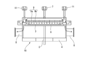
- FIG. 1A is a cross-sectional view of an ozone treatment apparatus including a shower head according to a first embodiment of the present invention
- FIG. 2B is a plan view of the shower head according to the first embodiment of the present invention. It is sectional drawing of the ozone treatment apparatus provided with the shower head which concerns on 2nd Embodiment of this invention.
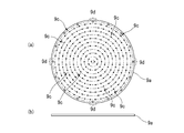
- FIG. 3A is a plan view of a first shower head
- FIG. 3B is a side view of the first shower head.
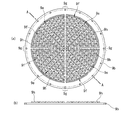
- FIG. 5A is a plan view of a second shower head
- FIG. 5B is a cross-sectional view taken along line AA of the second shower head in FIG.
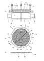
- (A) is a sectional view of an ozone treatment apparatus provided with a shower head according to a fifth embodiment of the present invention, (b) a plan view of an exhaust characteristic control plate, and (c) a longitudinal sectional view of an exhaust characteristic control plate. It is sectional drawing of the ozone treatment apparatus provided with the shower head which concerns on 6th Embodiment of this invention. (A) It is sectional drawing of the ozone treatment apparatus which concerns on 7th Embodiment of this invention, (b) Top view of a rotating slit, (c) Side view of a rotating slit. It is a sectional view of an ozone treatment device concerning an 8th embodiment of the present invention.
- a shower head and a processing apparatus according to an embodiment of the present invention will be described in detail with reference to the drawings.
- the processing apparatus is referred to as an ozone processing apparatus.
- FIG. 1 is a cross-sectional view of an ozone treatment apparatus 2 including a shower head 1 according to an embodiment of the present invention.
- the ozone processing apparatus 2 includes a processing chamber 4 in which a wafer 3 to be processed is disposed.
- the wafer 3 is placed on a rotation stage 6 (and a susceptor) supported by a rotation introducing machine 5.
- the susceptor is a wafer support provided with a heater for heating the wafer 3 and the like.
- a gas supply port 7 for supplying ozone as a material gas is provided at an upper portion of the processing chamber 4. Further, on the side of the processing chamber 4, there is provided an exhaust port 8 for discharging a gas such as ozone supplied to the wafer 3 and oxygen generated after the processing.
- the shower head 1 is provided in the processing chamber 4.
- the shower head 1 is provided at a position distant from the surface to be processed of the wafer 3 and opposed to the wafer 3.
- a gas ejection hole 1a is formed on a surface of the shower head 1 facing the wafer 3.
- the gas ejection holes 1a are formed at equal intervals in the vertical direction and the horizontal direction in the figure, but the arrangement of the gas ejection holes 1a is, for example, such that the center of the shower head 1 is one Arbitrary settings can be made, such as arranging them at equal intervals (excluding the exhaust gas flow path portion 1b described later) on the concentric circles at the center.
- the surface of the shower head 1 facing the wafer 3 is not limited to a circle, but may be, for example, a rectangle.
- an exhaust gas flow path 1b extending from the outer peripheral portion to the center of the shower head 1 is provided.
- the exhaust gas passage 1b is an area where gas does not blow out.
- the exhaust gas flow path portion 1b is a region where the gas ejection holes 1a are not formed, for example, a surface of the shower head 1 facing the wafer 3, and a plurality of the exhaust gas flow passage portions 1b are arranged at equal intervals in the circumferential direction of the shower head 1. .
- a region in which the gas ejection holes 1a are formed is provided in the center of the shower head 1, and an exhaust gas flow path portion 1b extending in the outer peripheral direction of the shower head 1 from the outer peripheral end of this region is provided.
- gas ejection holes 1a are respectively formed in regions sandwiched between the exhaust gas flow path portions 1b.
- the width of the exhaust gas flow path portion 1b is set, for example, to about 1.5 to 2 times the shortest distance between the adjacent gas ejection holes 1a.
- the ozone gas supplied from the gas supply port 7 is supplied to the wafer 3 through the gas ejection hole 1a of the shower head 1, and the wafer 3 is oxidized. Then, the ozone gas (including the decomposed gas after the reaction) supplied to the wafer 3 flows toward the outer periphery of the shower head 1 and is discharged from the exhaust port 8 to the outside of the processing chamber 4.
- the concentration (volume%) of the ozone gas supplied to the ozone treatment device 2 is not particularly limited, but for example, a high-concentration ozone gas of 20 vol% or more, more preferably 80 vol% or more is suitably used.
- the high-concentration ozone gas can be obtained by liquefying and separating only ozone from the ozone-containing gas based on the difference in vapor pressure, and then vaporizing the liquefied ozone again.
- An apparatus for obtaining a high-concentration ozone gas is disclosed in, for example, Japanese Patent Application Laid-Open Nos. 2001-304756 and 2003-20209.
- the apparatus for generating high-concentration ozone gas liquefies and separates only ozone based on a difference in vapor pressure between ozone and another gas (for example, oxygen) to generate high-concentration ozone (ozone concentration ⁇ 100 vol%).
- another gas for example, oxygen
- high-concentration ozone ozone concentration ⁇ 100 vol%.
- a commercially available device for generating a high-concentration ozone gas for example, there is a pure ozone generator (MPOG-HM1A1) manufactured by Meidensha.
- FIG. 2 is a cross-sectional view of an ozone treatment apparatus 10 including a shower head 9 according to a second embodiment of the present invention.
- the same components as those of the ozone treatment apparatus 2 according to the first embodiment are denoted by the same reference numerals, and detailed description is omitted. I do.
- the same reference numerals are given to the same configurations as those in the above-described embodiments, and detailed description will be omitted.
- the ozone treatment apparatus 10 includes first and second gas ejection holes 9 e and 9 f for ejecting different types of gas on the side of the shower head 9 facing the wafer 3. Two different gases are supplied to the wafer 3.
- the ozone processing apparatus 10 includes the processing chamber 4.
- a rotating stage 6 and a shower head 9 are provided in the processing chamber 4.
- a gas supply port 7 for supplying an ozone gas and a gas supply port 11 for supplying an additional gas (for example, a TEOS gas or an unsaturated hydrocarbon gas) that reacts with the ozone gas are provided at an upper portion of the processing chamber 4.
- the shower head 9 is provided in the processing chamber 4 at a position away from the wafer 3 placed on the rotary stage 6 so as to face the surface of the wafer 3 to be processed.
- the shower head 9 includes a first shower head 9a and a second shower head 9b.
- the first shower head 9a has a gas ejection hole 9c for ejecting ozone as a material gas on a surface facing the wafer 3, and a first ejection hole 9c.
- the shower head 9a includes an exhaust gas passage 9d extending from the outer periphery to the center.
- the gas ejection holes 9c are, for example, at equal intervals on a plurality of circumferences having different radii (excluding the exhaust gas flow path portion 9d) with the center of the surface of the first shower head 9a facing the wafer 3 as one center. Be placed. Note that the arrangement of the gas ejection holes 9c is not limited to the embodiment, and may be set arbitrarily.
- the exhaust gas flow path 9d is an area where gas does not blow out.
- the exhaust gas flow path portion 9d is a region where the gas ejection holes 9c are not formed, and is, for example, a surface facing the wafer 3 of the first shower head 9a and is arranged at equal intervals in a circumferential direction of the first shower head 9a.
- a region in which a gas ejection hole 9c is formed is provided at the center of the first shower head 9a, and an exhaust gas passage portion 9d extending from the outer peripheral end of this region in the outer peripheral direction of the first shower head 9a is provided.
- gas ejection holes 9c are respectively formed in regions interposed between the exhaust gas flow passage portions 9d.
- the width of the exhaust gas passage 9d is set, for example, to about 1 to 2 times the distance between the gas ejection holes 9c adjacent in the circumferential direction.
- the second shower head 9b has a first gas ejection hole 9e communicating with a gas ejection hole 9c of the first shower head 9a and a second gas ejection hole 9e on a surface facing the wafer 3.
- a second gas ejection hole 9f and an exhaust gas flow passage 9g extending from the outer peripheral portion to the center of the second shower head 9b are provided.
- the first gas ejection holes 9e are formed in accordance with the gas ejection holes 9c of the first shower head 9a.
- the second shower heads 9b are arranged at equal intervals on a concentric circle (excluding the exhaust gas flow path portion 9g) with the center of the surface facing the wafer 3 as one center.
- the second gas ejection holes 9f are, for example, on a plurality of circumferences having different radii (excluding the exhaust gas flow path portion 9g) with the center of the surface of the second shower head 9b facing the wafer 3 as one center. It is arranged at intervals.
- the second gas ejection holes 9f are alternately arranged with the first gas ejection holes 9e in a radial direction of a concentric circle where the second gas ejection holes 9f are arranged.
- the arrangement form of the second gas ejection holes 9f is not limited to the embodiment, and can be arbitrarily arranged.
- the exhaust gas passage 9g is an area where gas does not blow out.
- the exhaust gas passage portion 9g is a region where the first and second gas ejection holes 9e and 9f are not formed, and is, for example, a surface of the second shower head 9b facing the wafer 3, and the peripheral surface of the second shower head 9b.
- a plurality is provided at equal intervals in the direction.
- a region where the first and second gas ejection holes 9e and 9f are formed is provided at the center of the second shower head 9b, and extends from the outer peripheral end of this region in the outer peripheral direction of the second shower head 9b.
- An exhaust gas passage section 9g is provided.
- first and second gas ejection holes 9e and 9f are formed in regions interposed between the exhaust gas passage portions 9g, respectively.
- the width of the exhaust gas passage 9g is, for example, about 1 to 2 times the distance between the first gas ejection holes 9e (or the second gas ejection holes 9f) adjacent in the circumferential direction, or the adjacent gas ejection holes 9e. , 9f is set to about 1.5 to 2 times the shortest distance.
- the shortest distance between the first and second gas ejection holes 9e and 9f is set to be equal to the distance between the gas ejection surface of the shower head 9 and the surface of the wafer 3.
- a protruding portion 9h protruding in the direction of the first shower head 9a is provided on a surface of the second shower head 9b facing the first shower head 9a.
- the protruding portion 9h is provided upright along the gas ejection hole 9c of the first shower head 9a provided to face the second shower head 9b (except for a part of the exhaust gas flow passage portion 9g).
- a first gas ejection hole 9e is formed.
- this portion becomes a TEOS gas supply flow path.
- the TEOS gas is supplied to the wafer 3 from the second gas ejection hole 9f formed at the center of the second shower head 9b.
- the first shower head 9a and the second shower head 9b are provided so as to overlap with each other so that a surface from which gas supplied to the wafer 3 is blown out faces the wafer 3.
- the ozone gas supplied from the gas supply port 7 is supplied to the wafer 3 through the gas ejection holes 9c of the first shower head 9a and the first gas ejection holes 9e of the second shower head 9b.
- the TEOS gas supplied from the gas supply port 11 passes between the first shower head 9a and the second shower head 9b, and is supplied to the wafer 3 from the second gas ejection hole 9f. That is, the ozone gas and the TEOS gas are mixed on the surface of the wafer 3 and supplied to the wafer 3.
- the ozone gas and TEOS gas (including a reaction gas such as oxygen generated after the processing) provided on the wafer 3 flow toward the outer periphery of the shower head 9 and are discharged from the exhaust port 8 to the outside of the processing chamber 4.
- FIG. 5A is a cross-sectional view of an ozone treatment apparatus 13 including a shower head 12 according to a third embodiment of the present invention.
- the shower head 12 according to the third embodiment includes the shower head 1 according to the first embodiment and an exhaust direction control plate 14. Therefore, a configuration different from the shower head 1 according to the first embodiment will be described in detail.
- the exhaust direction control plate 14 is a plate extending from the center of the shower head 1 in the outer peripheral direction, and extends from the surface of the shower head 1 facing the wafer 3 toward the wafer 3. It is provided standing up.
- the exhaust direction control plates 14 are provided, for example, in the middle between the exhaust gas flow passage portions 1b adjacent in the circumferential direction of the shower head 1, respectively.
- the shower head 1 blows out from the gas blowing holes 1 a of the shower head 1. Gas can be quickly exhausted from the closest radial exhaust gas flow path 1b.
- FIG. 6A is a cross-sectional view of an ozone treatment apparatus 16 including a shower head 15 according to a fourth embodiment of the present invention.
- the shower head 15 according to the fourth embodiment is the same as the shower head 9 according to the second embodiment, except that the same exhaust direction control plate 14 as the third embodiment is provided.
- the exhaust direction control plate 14 is provided upright from the surface of the shower head 9 facing the wafer 3, for example.
- the exhaust direction control plates 14 are respectively provided in the center of the exhaust gas flow passage portions 9g adjacent to the shower head 9 in the circumferential direction.
- the first gas ejection holes 9e of the shower head 9 and The gas ejected from the second gas ejection holes 9f can be quickly exhausted from the nearest radial exhaust gas passage 9g.
- FIG. 7A is a cross-sectional view of an ozone treatment apparatus 18 including a shower head 17 according to a fifth embodiment of the present invention.
- the shower head 17 according to the fifth embodiment includes an exhaust characteristic control plate 19 on the outer peripheral portion of the shower head 1 according to the first embodiment. Therefore, a configuration different from the shower head 1 according to the first embodiment will be described in detail.
- the exhaust characteristic control plate 19 is provided on the ceiling of the processing chamber 4 so as to cover, for example, the outer periphery of the shower head 1.
- the shower head 17 can be configured by providing the exhaust characteristic control plate 19 directly on the outer peripheral portion of the shower head 1.
- the exhaust characteristic control plate 19 is a ring-shaped member having a wall 19a extending in the normal direction of the gas ejection surface of the shower head 17.
- the protruding length of the wall portion 19 a is appropriately set according to the pressure between the shower head 17 and the wafer 3.
- a space 20 through which gas supplied to the wafer 3 is discharged is provided between the inner peripheral surface of the wall 19a (or the tip of the wall 19a) and the side of the wafer 3 or the rotary stage 6. .
- the ozone gas supplied from the shower head 17 passes through the space 20 and is discharged from the exhaust port 8 to the outside of the processing chamber 4.
- the pressure over the entire surface of the wafer 3 can be made more uniform.
- FIG. 8 is a cross-sectional view of an ozone treatment apparatus 22 including a shower head 21 according to a sixth embodiment of the present invention.
- the shower head 21 according to the sixth embodiment has the same exhaust characteristic control plate 19 as the fifth embodiment in the shower head 9 according to the second embodiment.
- the exhaust characteristic control plate 19 is provided, for example, on the outer peripheral portion of the surface of the shower head 9 facing the wafer 3.
- the shower head 21 can be configured by providing the exhaust characteristic control plate 19 on the ceiling of the processing chamber 4.
- the pressure over the entire surface of the wafer 3 can be made more uniform.
- FIG. 9A is a sectional view of an ozone treatment apparatus 23 according to a seventh embodiment of the present invention.
- the ozone treatment device 23 according to the seventh embodiment is the same as the ozone treatment device 2 according to the first embodiment, except that a rotary slit 24 is provided. Therefore, a configuration different from the ozone treatment apparatus 2 according to the first embodiment will be described in detail.
- the rotation slit 24 and the rotation stage 6 (and the susceptor) are rotatably supported by a biaxial rotation introducing machine 25.
- the rotation stage 6 is attached to the first stage of the rotation introducing machine 25, and the rotation slit 24 is attached to the second stage of the rotation introduction machine 25.
- the rotary slit 24 includes a wall 24a that stands in the normal direction of the surface of the wafer 3 to be processed.
- the wall portions 24a are provided at predetermined intervals so as to surround the outer periphery of the rotary stage 6, and a slit 24b is formed between the wall portions 24a.
- the gas supplied to the wafer 3 can be stirred. it can.
- FIG. 10 is a sectional view of an ozone treatment apparatus 26 according to the eighth embodiment of the present invention.
- the ozone treatment apparatus 26 according to the eighth embodiment is the same as the ozone treatment apparatus 10 according to the second embodiment, except that the ozone treatment apparatus 26 according to the second embodiment is provided with the same rotary slit 24 as in the seventh embodiment.
- the wafer 3 is provided to the wafer 3 by providing the rotary slit 24. Gas can be agitated.
- each pressure (Pa, Pc, Pe) indicates a gas flow rate of 50 sccm (sccm: 1 atm (1013 hPa), ccm (cm 3 / min) at 25 ° C. )) Is displayed as a ratio to the exhaust port pressure (Pe).
- the ozone treatment apparatuses 2, 18, and 27 shown in FIGS. 11B to 13B show approximate locations of the respective pressures (Pa, Pc, Pe) in the respective apparatuses.
- FIG. 11A is a characteristic showing the relationship between the gas central flow rate (Pc), the wafer 3 peripheral pressure (Pa), the exhaust port 8 pressure (Pe), and the gas supply flow rate of the ozone treatment apparatus 2 according to the first embodiment.
- Pc gas central flow rate
- Pa wafer 3 peripheral pressure
- Pe exhaust port 8 pressure
- FIG. 12A shows the relationship between the central pressure (Pc) of the wafer 3, the peripheral pressure (Pa) of the wafer 3, the pressure of the exhaust port 8 (Pe), and the gas supply flow rate in the ozone treatment apparatus 18 according to the fifth embodiment. It is a characteristic diagram.
- FIG. 13A is a characteristic diagram showing a relationship between the gas 3 flow rate and the central pressure (Pc) of the wafer 3, the peripheral pressure (Pa) of the wafer 3, and the pressure (Pe) of the exhaust port 8 of the ozone treatment apparatus 27 according to the comparative example. It is.
- an ozone treatment device 27 according to a comparative example is a treatment device including a shower head 28 according to a comparative example.
- gas ejection holes 28a are uniformly formed on the surface of the shower head 28 facing the wafer 3.
- the ozone treatment apparatus 2 according to the first embodiment makes the gas supply pressure (that is, the supply amount of the gas supplied from the shower head 1) uniform over the entire surface (the central part and the peripheral part) of the wafer 3.
- the gas supply pressure that is, the supply amount of the gas supplied from the shower head 1
- uniform ozone treatment can be performed on the entire surface of the wafer 3. Since the wafer 3 is mounted on the rotary stage 6, by rotating the wafer 3, uniform ozone treatment can be performed on the entire surface of the wafer 3.
- the difference in gas supply pressure near the center and the periphery of the surface of the wafer 3 is almost eliminated.
- the ozone processing apparatus 18 according to the fifth embodiment The pressure (Pc, Pa) near the center and the periphery of the surface of the wafer 3 increases.
- the ozone treatment apparatus 18 according to the fifth embodiment has a smaller pressure difference near the center and the periphery of the entire surface of the wafer 3 than the ozone treatment apparatus 2 according to the first embodiment.
- the ozone processing apparatus 27 makes the gas supply pressure (that is, the supply amount of the gas supplied from the shower head 17) uniform over the entire surface (the central part and the peripheral part) of the wafer 3. Thus, more uniform ozone treatment can be performed on the entire surface of the wafer 3.
- the shower head 1 As described above, the shower head 1 according to the first embodiment of the present invention (the same applies to the shower heads 9, 12, 15, 17, and 21 according to other embodiments; the same applies hereinafter) and the ozone treatment apparatus 2 (others). The same applies to the ozone treatment apparatuses 10, 13, 16, 18, 22, 23, and 26 according to this embodiment. The same applies to the following description).
- the gas material gas, additive gas, and gas such as oxygen generated after the reaction supplied to the wafer 3 quickly passes between the exhaust gas flow path 1b and the wafer 3 and is exhausted.
- the difference in the gas supply pressure in the vicinity of the central part and in the vicinity of the peripheral part can be almost eliminated. That is, the pressure difference between the shower head 1 and the wafer 3 in the horizontal direction on the processing surface of the wafer 3 can be reduced.
- the wafer 3 is set on the rotary stage 6, by rotating the wafer 3, the entire surface of the wafer 3 can be uniformly treated with ozone.
- the amount of the highly reactive high-concentration ozone gas supplied from the shower head 28 supplied onto the wafer 3 is larger at the peripheral portion of the wafer 3 having a lower pressure. Therefore, the ozone treatment effect around the wafer 3 is increased, and the uniformity of the ozone treatment on the entire surface of the wafer 3 is reduced.
- the ozone gas (including the oxygen gas generated after the reaction) supplied to the central portion of the wafer 3 has a discharge gas flow. Since the gas is quickly exhausted through the space between the path portion 1b and the wafer 3, a high concentration ozone gas is always supplied to the wafer 3 at a uniform gas pressure on the surface of the wafer 3. Therefore, the high reactivity of the high-concentration ozone gas can be effectively applied to the entire surface of the wafer 3, and in various oxidation processes using the high reactivity of the high-concentration ozone gas, the object of the ozone treatment to be enlarged becomes large. An even process can be performed on an object (such as a wafer 3 or a glass substrate).
- a shower head for supplying a plurality of gases (two or more gases) capable of simultaneously supplying a high-concentration ozone gas and a highly reactive gas (hereinafter, additional gas) is used.
- additional gas a highly reactive gas
- the pressure of the additive gas other than the high-concentration ozone gas may be high, and as described above, unless the gas at the center of the wafer 3 is quickly exhausted, the pressure of the additive gas or the gas generated by the reaction between the ozone gas and the additive gas.
- the ozone gas having a higher concentration to be supplied to the central portion of the wafer 3, and the ozone gas is supplied to the peripheral portion of the wafer 3 in an uneven manner.
- the shower head 9 according to the second embodiment (the same applies to shower heads according to other embodiments; the same applies hereinafter) and the ozone treatment device 10 (the ozone treatment devices according to other embodiments also apply).
- the pressure difference between the shower head 9 and the wafer 3 in the horizontal direction on the surface to be processed of the wafer 3 can be reduced, and uniform processing can be performed on the entire surface of the wafer 3. . That is, according to the shower head 9 and the ozone treatment apparatus 10 according to the second embodiment, when a plurality of different gases are supplied from the shower head 9 to the wafer 3, some of the gases are biased due to a difference in pressure between the gases. Is suppressed from being supplied to the wafer 3, and more uniform processing can be performed.
- the exhaust direction control plate 14 described in the third and fourth embodiments the flow direction of the exhaust gas flowing between the shower heads 1 and 9 and the wafer 3 is controlled, and the gas supplied to the wafer 3 is reduced. It can be discharged out of the processing chamber 4 more quickly.
- the exhaust characteristics of the gas exhausted from the wafer 3 are slightly reduced. Can be stirred.
- the shower head and the processing device of the present invention have been described with reference to the specific embodiments.
- the shower head and the processing device of the present invention are not limited to the embodiments, and the characteristics thereof are not impaired.
- the design can be changed as appropriate, and the changed design also belongs to the technical scope of the present invention.
- a shower head and a processing apparatus including a part of the configuration of the ozone processing apparatus described in the embodiment of the present invention, or a shower head and a processing combining a part of the configuration of the ozone processing apparatus described in the embodiment of the present invention
- the device also belongs to the technical scope of the present invention.
- the processing apparatus is not limited to an apparatus for oxidizing the wafer 3 with ozone, and the present invention can be applied to an apparatus for supplying a gas from a shower head to an object to be processed.
- the object to be processed is not limited to the wafer 3, but may be a glass substrate, a resin substrate, a resin film, or the like. That is, in the field of silicon semiconductors, a circular substrate as in the embodiment is used as an object to be processed, and in the field of displays and the like, an object to be processed such as a rectangular substrate is used according to the purpose. Further, the shower head and the processing apparatus of the present invention are applied not only to a processing apparatus for supplying a gas to a fixed substrate, but also to a processing apparatus for supplying a gas to a film moving by a roll-to-roll method. You can also.
- Examples of the processing apparatus using a high-concentration ozone gas include wafer cleaning, formation of an oxide film such as silicon oxide (for example, Japanese Patent Application Laid-Open No. 8-335576), CVD, ALD (Atomic Layer Deposition), and ashing. Used as an oxidizing agent in various processes.
- the shower head and the processing apparatus of the present invention to each of these processing apparatuses, it is possible to perform ozone treatment with excellent in-plane uniformity on an object to be oxidized. For example, when performing ashing (etching) or cleaning using ozone gas, unsaturated hydrocarbon gas is supplied from a first gas ejection hole of the shower head, and ozone gas is supplied from a second gas ejection hole.
- a TEOS gas (a raw material gas for forming an SiO 2 film) or a TMA (trimethylaluminium) is supplied from the first gas ejection hole of the shower head in a state where the processing furnace is filled with ozone in advance.
- a gas containing various organic metals for example, Hf, Zn, Zr, Ti, etc.
- the gas supplied from the shower head is an arbitrary gas selected according to the purpose, and does not necessarily need to include ozone gas.
- the effects of the shower head and the processing apparatus of the present invention can be obtained. That is, as long as the gas supplied from the shower head to the wafer is at least one type, any gas can be supplied from the shower head to the wafer.
- a mode in which a plurality of gases are mixed in a preceding stage of the shower head and the mixed gas is supplied from the shower head to the wafer may be adopted.
- the number of the exhaust gas passages 1a, 9d, 9g is not limited to the embodiment, and a plurality of exhaust gas passages are formed according to the processing apparatus.
Landscapes
- Chemical & Material Sciences (AREA)
- General Chemical & Material Sciences (AREA)
- Chemical Kinetics & Catalysis (AREA)
- Engineering & Computer Science (AREA)
- Materials Engineering (AREA)
- Mechanical Engineering (AREA)
- Metallurgy (AREA)
- Organic Chemistry (AREA)
- Drying Of Semiconductors (AREA)
- Chemical Vapour Deposition (AREA)
- Exposure Of Semiconductors, Excluding Electron Or Ion Beam Exposure (AREA)
- Cleaning Or Drying Semiconductors (AREA)
Abstract
ウェハ(3)が配置される処理チャンバ(4)と、処理チャンバ(4)内に設けられるシャワーヘッド(1)を備えるオゾン処理装置(2)である。シャワーヘッド(1)を、ウェハ(3)の被処理面から離れた位置であって、ウェハ(3)と向かい合うように備える。シャワーヘッド(1)のウェハ(3)と向かい合う面に、ウェハ(3)に供されるガスが噴き出すガス噴出穴(1a)と、ガスが噴き出さない領域である排出ガス流路部(1b)を設ける。シャワーヘッド(1)の中心部にガス噴出穴(1a)が形成される領域を設け、この領域からシャワーヘッド(1)の外周方向に延びる排出ガス流路部(1b)をシャワーヘッド(1)の周方向に並べて複数配置する。この排出ガス流路部(1b)に挟まれた領域にそれぞれガス噴出穴(1a)を形成する。
Description
本発明は、シャワーヘッドおよびシャワーヘッドを備えた処理装置に関する。特に、被処理体に材料ガス等の反応に供されるガスを供給するシャワーヘッドの構造に関する。
シャワーヘッドは、例えば、CVD(Chemical Vapor Deposition)やオゾン酸化等を行う処理装置内に設けられ、ウェハ等の被処理体上に材料ガス等の反応に供されるガスを供給する(例えば、特許文献1)。
シャワーヘッド表面上には、ガス噴出穴が均等に配置されており、そこから噴き出すガスは、一見、ウェハ等の被処理体に均等に当たるように思われる。
しかしながら、被処理体に供給されたガスは、被処理体の中心から外周方向に流れるため、被処理体の中央部に噴き出したガスの排気は、被処理体の周辺部に噴き出したガスに妨げられる。したがって、被処理体の中央部に噴き出したガスは、被処理体の周辺部に噴き出したガスと比較して排気され難くなる。その影響で、被処理体表面上の中央部と周辺部で圧力差(中央部の圧力>周辺部の圧力)が生じ、ガスは被処理体の中央部に供給され難くなり、排気が速やかでより圧力の低い被処理体の周辺部に供給され易くなる。
このように、被処理体に供給されるガスに偏りが生じると、被処理体の処理面に対して均一性に優れた処理ができなくなるおそれがある。
本発明は、上記事情に鑑みてなされたものであり、シャワーヘッドと被処理体の間における被処理体の被処理面の水平方向の圧力差を低減する技術を提供することを目的としている。
上記目的を達成する本発明のシャワーヘッドの一態様は、
被処理体に対向する側に多数のガス噴出穴を有し、前記被処理体に対してガスを供給するシャワーヘッドであって、
前記シャワーヘッドの前記被処理体に対向する面に、前記ガスが噴き出さない領域を、前記シャワーヘッドの外周部から前記シャワーヘッドの中心部に延びるように複数備え、
前記ガスが噴き出さない領域に挟まれた領域に、前記ガス噴出穴が形成される。
被処理体に対向する側に多数のガス噴出穴を有し、前記被処理体に対してガスを供給するシャワーヘッドであって、
前記シャワーヘッドの前記被処理体に対向する面に、前記ガスが噴き出さない領域を、前記シャワーヘッドの外周部から前記シャワーヘッドの中心部に延びるように複数備え、
前記ガスが噴き出さない領域に挟まれた領域に、前記ガス噴出穴が形成される。
また、上記目的を達成する本発明のシャワーヘッドの他の態様は、上記のシャワーヘッドにおいて、
前記ガスは、異なる種類の複数のガスであり、
前記シャワーヘッドの前記被処理体に対向する側に、異なる種類のガスをそれぞれ供給するガス噴出穴が備えられる。
前記ガスは、異なる種類の複数のガスであり、
前記シャワーヘッドの前記被処理体に対向する側に、異なる種類のガスをそれぞれ供給するガス噴出穴が備えられる。
また、上記目的を達成する本発明のシャワーヘッドの他の態様は、上記のシャワーヘッドにおいて、
前記シャワーヘッドの前記被処理体に対向する側に、前記シャワーヘッドの外側から前記シャワーヘッドの中心部に延びる排気方向制御板が立設される。
前記シャワーヘッドの前記被処理体に対向する側に、前記シャワーヘッドの外側から前記シャワーヘッドの中心部に延びる排気方向制御板が立設される。
また、上記目的を達成する本発明のシャワーヘッドの他の態様は、上記のシャワーヘッドにおいて、
前記シャワーヘッドは、前記被処理体に対向する側に、前記シャワーヘッドの外周に沿って立設する排気特性制御板を備える。
前記シャワーヘッドは、前記被処理体に対向する側に、前記シャワーヘッドの外周に沿って立設する排気特性制御板を備える。
また、上記目的を達成する本発明の処理装置の一態様は、
被処理体が配置される処理チャンバと、
前記処理チャンバに備えられ、前記被処理体が載置されるステージと、
前記ステージ上に載置された前記被処理体と対向して備えられ、前記被処理体に対してガスを供給するシャワーヘッドと、を備え、
前記シャワーヘッドの前記被処理体と対向する面には、前記ガスが噴き出さない領域が、前記シャワーヘッドの外周部から前記シャワーヘッドの中心部に延びるように複数備えられ、
前記ガスが噴き出さない領域に挟まれた領域に、前記ガスが噴き出すガス噴出穴が複数形成される。
被処理体が配置される処理チャンバと、
前記処理チャンバに備えられ、前記被処理体が載置されるステージと、
前記ステージ上に載置された前記被処理体と対向して備えられ、前記被処理体に対してガスを供給するシャワーヘッドと、を備え、
前記シャワーヘッドの前記被処理体と対向する面には、前記ガスが噴き出さない領域が、前記シャワーヘッドの外周部から前記シャワーヘッドの中心部に延びるように複数備えられ、
前記ガスが噴き出さない領域に挟まれた領域に、前記ガスが噴き出すガス噴出穴が複数形成される。
また、上記目的を達成する本発明の処理装置の他の態様は、上記の処理装置において、
前記ガスは、異なる種類の複数のガスであり、
前記シャワーヘッドの前記被処理体に対向する側に、異なる種類のガスをそれぞれ供給するガス噴出穴が備えられる。
前記ガスは、異なる種類の複数のガスであり、
前記シャワーヘッドの前記被処理体に対向する側に、異なる種類のガスをそれぞれ供給するガス噴出穴が備えられる。
また、上記目的を達成する本発明の処理装置の他の態様は、上記の処理装置において、
前記シャワーヘッドの前記被処理体に対向する側に、前記シャワーヘッドの外側から前記シャワーヘッドの中心部に延びる排気方向制御板が立設される。
前記シャワーヘッドの前記被処理体に対向する側に、前記シャワーヘッドの外側から前記シャワーヘッドの中心部に延びる排気方向制御板が立設される。
また、上記目的を達成する本発明の処理装置の他の態様は、上記の処理装置において、
前記シャワーヘッドまたは前記処理チャンバに、前記シャワーヘッドの外周に沿って立設する排気特性制御板を備える。
前記シャワーヘッドまたは前記処理チャンバに、前記シャワーヘッドの外周に沿って立設する排気特性制御板を備える。
また、上記目的を達成する本発明の処理装置の他の態様は、上記の処理装置において、
前記シャワーヘッドは、前記被処理体と向かい合う側の面が円形であり、
前記処理チャンバには、前記ガスが排出されるスリットが形成された板が、前記シャワーヘッドの外周に沿って、前記被処理体の側面と向かい合うように、備えられ、
前記スリットが形成された板は、前記シャワーヘッドの前記被処理体と向かい合う側の面の中心を軸として回転可能に支持される。
前記シャワーヘッドは、前記被処理体と向かい合う側の面が円形であり、
前記処理チャンバには、前記ガスが排出されるスリットが形成された板が、前記シャワーヘッドの外周に沿って、前記被処理体の側面と向かい合うように、備えられ、
前記スリットが形成された板は、前記シャワーヘッドの前記被処理体と向かい合う側の面の中心を軸として回転可能に支持される。
以上の発明によれば、シャワーヘッドと被処理体の間における被処理体の被処理面の水平方向の圧力差を低減することができる。
本発明の実施形態に係るシャワーヘッドおよび処理装置について、図面に基づいて詳細に説明する。実施形態の説明では、処理装置をオゾン処理装置という。
図1は、本発明の実施形態に係るシャワーヘッド1を備えるオゾン処理装置2の断面図である。オゾン処理装置2は、被処理体であるウェハ3が配置される処理チャンバ4を備える。ウェハ3は、回転導入機5に支持された回転ステージ6(およびサセプタ)上に載置される。サセプタは、ウェハ3を加熱するヒータ等を備えたウェハ支持体である。
処理チャンバ4の上部には、材料ガスであるオゾンを供給するガス供給口7が備えられる。また、処理チャンバ4の側部には、ウェハ3に供されたオゾンおよび処理後に生成する酸素等のガスが排出される排気口8が備えられる。
シャワーヘッド1は、処理チャンバ4内に備えられる。シャワーヘッド1は、ウェハ3の被処理面から離れた位置であって、ウェハ3と向かい合うように備えられる。
図1(b)に示すように、シャワーヘッド1のウェハ3と向かい合う面には、ガス噴出穴1aが形成される。実施形態の説明では、ガス噴出穴1aは、図中縦方向と横方向に等間隔で並んで形成されているが、ガス噴出穴1aの配置態様は、例えば、シャワーヘッド1の中心を一つの中心とした同心円上にそれぞれ等間隔(後述の排出ガス流路部1bを除く)で配置する等、任意に設定することができる。また、シャワーヘッド1のウェハ3と向かい合う面は、円形に限定されるものではなく、例えば、矩形であってもよい。
シャワーヘッド1のウェハ3と向かい合う面には、シャワーヘッド1の外周部から中心部に延びる排出ガス流路部1bが設けられる。排出ガス流路部1bは、ガスが噴き出さない領域である。排出ガス流路部1bは、ガス噴出穴1aが形成されない領域であり、例えば、シャワーヘッド1のウェハ3と向かい合う面であって、シャワーヘッド1の周方向に等間隔に並んで複数配置される。例えば、シャワーヘッド1の中心部にガス噴出穴1aが形成される領域が設けられ、この領域の外周端部からシャワーヘッド1の外周方向に延びる排出ガス流路部1bが設けられる。そして、排出ガス流路部1bに挟まれた領域にそれぞれガス噴出穴1aが形成される。排出ガス流路部1bの幅は、例えば、隣り合うガス噴出穴1aの最短距離の1.5倍から2倍程度に設定される。シャワーヘッド1に排出ガス流路部1bを備えることで、例えば、ガス噴出穴1aの最短間隔が、シャワーヘッド1のガス噴出し面とウェハ3表面との距離よりも広い場合でも、シャワーヘッド1の中心部から、排気方向(円筒チャンバで真下に排気ポートを有する場合は、ウェハ3の径方向)に向かって排出ガス流路部1bの幅を有する排気流路が形成される。
ガス供給口7から供給されたオゾンガスは、シャワーヘッド1のガス噴出穴1aを通ってウェハ3に供給され、ウェハ3の酸化処理が行われる。そして、ウェハ3に供されたオゾンガス(反応後の分解ガスを含む)は、シャワーヘッド1の外周方向に流れ、排気口8から処理チャンバ4の外部に排出される。
オゾン処理装置2に供給されるオゾンガスの濃度(体積%)は、特に限定するものではないが、例えば、20体積%以上、より好ましくは、80体積%以上の高濃度のオゾンガスが好適に用いられる。高濃度のオゾンガスは、オゾン含有ガスから蒸気圧の差に基づいてオゾンのみを液化分離した後、再び液化したオゾンを気化させて得ることができる。高濃度のオゾンガスを得るための装置は、例えば、特開2001-304756号公報や特開2003-20209号公報の特許文献に開示されている。これらの高濃度のオゾンガスを生成する装置は、オゾンと他のガス(例えば、酸素)の蒸気圧の差に基づきオゾンのみを液化分離して高濃度のオゾン(オゾン濃度≒100vol%)を生成している。特に、オゾンのみを液化および気化させるチャンバを複数備えると、これらのチャンバを個別に温度制御することにより、連続的に高濃度のオゾンガスを供給することができる。なお、高濃度のオゾンガスを生成する市販の装置として、例えば、明電舎製のピュアオゾンジェネレータ(MPOG-HM1A1)がある。
図2は、本発明の第2実施形態に係るシャワーヘッド9を備えたオゾン処理装置10の断面図である。なお、本発明の第2実施形態に係るシャワーヘッド9およびオゾン処理装置10の説明では、第1実施形態に係るオゾン処理装置2と同様の構成については同じ符号を付し、詳細な説明を省略する。同様に、以下の第3~第8実施形態の説明において、既出の実施形態と同様の構成については同じ符号を付し、詳細な説明を省略する。
本発明の第2実施形態に係るオゾン処理装置10は、シャワーヘッド9のウェハ3と向かい合う側に、異なる種類のガスが噴き出す第1、第2ガス噴出穴9e、9fを備え、シャワーヘッド9から異なる2種類のガスをウェハ3に供するものである。
オゾン処理装置10は、処理チャンバ4を備える。処理チャンバ4内には、回転ステージ6やシャワーヘッド9が備えられる。また、処理チャンバ4の上部には、オゾンガスを供給するガス供給口7と、オゾンガスと反応する添加ガス(例えば、TEOSガスや不飽和炭化水素ガス)を供給するガス供給口11が備えられる。
シャワーヘッド9は、処理チャンバ4内であって、回転ステージ6上に載置されたウェハ3から離れた位置に、ウェハ3の被処理面と向かい合うように備えられる。シャワーヘッド9は、第1シャワーヘッド9aと第2シャワーヘッド9bを備える。
図3に示すように、第1シャワーヘッド9aは、第1実施形態で説明したシャワーヘッド1と同様に、ウェハ3と向かい合う面に、材料ガスであるオゾンが噴き出すガス噴出穴9cと、第1シャワーヘッド9aの外周部から中心部に延びる排出ガス流路部9dを備える。
ガス噴出穴9cは、例えば、第1シャワーヘッド9aのウェハ3と向かい合う面の中心を一つの中心とした、半径が異なる複数の円周上(排出ガス流路部9dを除く)に等間隔で配置される。なお、ガス噴出穴9cの配置形態は、実施形態に限定されるものではなく、任意に設定される。
排出ガス流路部9dは、ガスが噴き出さない領域である。排出ガス流路部9dは、ガス噴出穴9cが形成されない領域であり、例えば、第1シャワーヘッド9aのウェハ3と向かい合う面であって、第1シャワーヘッド9aの周方向に等間隔に並んで複数備えられる。例えば、第1シャワーヘッド9aの中心部には、ガス噴出穴9cが形成される領域が設けられ、この領域の外周端部から第1シャワーヘッド9aの外周方向に延びる排出ガス流路部9dが設けられる。そして、排出ガス流路部9dに挟まれた領域にそれぞれガス噴出穴9cが形成される。排出ガス流路部9dの幅は、例えば、周方向に隣接するガス噴出穴9cの距離の1倍から2倍程度に設定される。
図4(a)に示すように、第2シャワーヘッド9bは、ウェハ3と向かい合う面に、第1シャワーヘッド9aのガス噴出穴9cと連通する第1ガス噴出穴9eと、TEOSガスが噴き出す第2ガス噴出穴9fと、第2シャワーヘッド9bの外周部から中心部に延びる排出ガス流路部9gを備える。
第1ガス噴出穴9eは、第1シャワーヘッド9aのガス噴出穴9cに応じて形成される。例えば、第2シャワーヘッド9bのウェハ3と向かい合う面の中心を一つの中心とした同心円上(排出ガス流路部9gを除く)に等間隔で配置される。
第2ガス噴出穴9fは、例えば、第2シャワーヘッド9bのウェハ3と向かい合う面の中心を一つの中心とした、半径が異なる複数の円周上(排出ガス流路部9gを除く)に等間隔で配置される。第2ガス噴出穴9fは、第2ガス噴出穴9fが配置される同心円の径方向に対して第1ガス噴出穴9eと交互に配置される。第2ガス噴出穴9fの配置形態は、実施形態に限定されるものではなく、任意に配置することができる。
排出ガス流路部9gは、ガスが噴き出さない領域である。排出ガス流路部9gは、第1、第2ガス噴出穴9e、9fが形成されない領域であり、例えば、第2シャワーヘッド9bのウェハ3と向かい合う面であって、第2シャワーヘッド9bの周方向に等間隔に並んで複数備えられる。例えば、第2シャワーヘッド9bの中心部には、第1、第2ガス噴出穴9e、9fが形成される領域が設けられ、この領域の外周端部から第2シャワーヘッド9bの外周方向に延びる排出ガス流路部9gが設けられる。そして、排出ガス流路部9gに挟まれた領域にそれぞれ第1、第2ガス噴出穴9e、9fが形成される。排出ガス流路部9gの幅は、例えば、周方向に隣接する第1ガス噴出穴9e(または、第2ガス噴出穴9f)の距離の1倍から2倍程度、または隣り合うガス噴出穴9e、9fの最短距離の1.5倍から2倍程度に設定される。第2シャワーヘッド9bに排出ガス流路部9gを備えることで、例えば、第1、第2ガス噴出穴9e、9fの最短間隔が、シャワーヘッド9のガス噴出し面とウェハ3表面との距離よりも広い場合でも、シャワーヘッド9の中心部から、排気方向(円筒チャンバで真下に排気ポートを有する場合は、ウェハ3の径方向)に向かって排出ガス流路部9gの幅を有する排気流路が形成される。
図4(b)に示すように、第2シャワーヘッド9bの第1シャワーヘッド9aと向かい合う面には、第1シャワーヘッド9a方向に突出する突出部9hが設けられる。突出部9hは、第2シャワーヘッド9bと向かい合って備えられる第1シャワーヘッド9aのガス噴出穴9cに沿って立設され(排出ガス流路部9gの一部を除く)、この突出部9hに第1ガス噴出穴9eが形成される。なお、図4(a)に示すように、第2シャワーヘッド9bの径方向に沿って、突出部9hが備えられない部分を設けることによって、この部分がTEOSガスの供給流路となる。これにより、第2シャワーヘッド9bの中央部に形成された第2ガス噴出穴9fからウェハ3にTEOSガスが供されることとなる。
図2に示すように、第1シャワーヘッド9aと第2シャワーヘッド9bは、ウェハ3に供されるガスが噴き出す面がウェハ3と向かい合うように重ねて備えられる。そして、ガス供給口7から供給されたオゾンガスは、第1シャワーヘッド9aのガス噴出穴9c、第2シャワーヘッド9bの第1ガス噴出穴9eを通って、ウェハ3に供される。また、ガス供給口11から供給されたTEOSガスは、第1シャワーヘッド9aと第2シャワーヘッド9bの間を通って、第2ガス噴出穴9fからウェハ3に供される。つまり、オゾンガスとTEOSガスは、ウェハ3表面上で混合されてウェハ3に供される。ウェハ3上に供されたオゾンガスおよびTEOSガス(処理後に生成した酸素等の反応ガスを含む)は、シャワーヘッド9の外周方向に流れ、排気口8から処理チャンバ4の外部に排出される。
図5(a)は、本発明の第3実施形態に係るシャワーヘッド12を備えたオゾン処理装置13の断面図である。第3実施形態に係るシャワーヘッド12は、第1実施形態に係るシャワーヘッド1に排気方向制御板14を備えたものである。よって、第1実施形態に係るシャワーヘッド1と異なる構成について詳細に説明する。
図5(b)、(c)に示すように、排気方向制御板14は、シャワーヘッド1の中心部から外周方向に延びる板であり、シャワーヘッド1のウェハ3と向かい合う面からウェハ3方向に立設して備えられる。排気方向制御板14は、例えば、シャワーヘッド1の周方向に隣接する排出ガス流路部1b間の真ん中にそれぞれ設けられる。
第3実施形態に係るシャワーヘッド12によれば、第1実施形態に係るシャワーヘッド1の奏する効果に加えて、排気方向制御板14を設けることで、シャワーヘッド1のガス噴出穴1aから噴き出したガスを、一番近い径方向の排出ガス流路部1bから速やかに排気することができる。
図6(a)は、本発明の第4実施形態に係るシャワーヘッド15を備えたオゾン処理装置16の断面図である。第4実施形態に係るシャワーヘッド15は、第2実施形態に係るシャワーヘッド9に、第3実施形態と同様の排気方向制御板14を備えたものである。
排気方向制御板14は、例えば、シャワーヘッド9のウェハ3と向き合う面から立設して備えられる。排気方向制御板14は、シャワーヘッド9の周方向に隣接する排出ガス流路部9gの真ん中にそれぞれ設けられる。
第4実施形態に係るシャワーヘッド15によれば、第2実施形態に係るシャワーヘッド9の奏する効果に加えて、排気方向制御板14を設けることで、シャワーヘッド9の第1ガス噴出穴9eおよび第2ガス噴出穴9fから噴き出したガスを、一番近い径方向の排出ガス流路部9gから速やかに排気することができる。
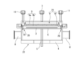
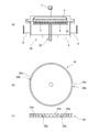
図7(a)は、本発明の第5実施形態に係るシャワーヘッド17を備えたオゾン処理装置18の断面図である。第5実施形態に係るシャワーヘッド17は、第1実施形態に係るシャワーヘッド1の外周部に、排気特性制御板19を備えたものである。よって、第1実施形態に係るシャワーヘッド1と異なる構成について詳細に説明する。
排気特性制御板19は、例えば、シャワーヘッド1の外周を覆うように、処理チャンバ4の天井部に設けられる。なお、シャワーヘッド1の外周部に直接排気特性制御板19を設けてシャワーヘッド17を構成することもできる。
図7(b)、(c)に示すように、排気特性制御板19は、シャワーヘッド17のガス噴出し面の法線方向に延在する壁部19aを備えるリング状の部材である。
壁部19aの突出長さは、シャワーヘッド17とウェハ3間の圧力に応じて適宜設定される。壁部19aの内周面(または、壁部19aの先端部)とウェハ3や回転ステージ6の側部との間には、ウェハ3に供されたガスが排出される空間部20が設けられる。シャワーヘッド17から供されたオゾンガスは、空間部20を通って、排気口8から処理チャンバ4の外部に排出される。排気特性制御板19を設けることで、ウェハ3に供されたガスの排気特性が悪くなるが、ウェハ3全表面上の圧力を均等にすることができる。
第5実施形態に係るシャワーヘッド17によれば、第1実施形態に係るシャワーヘッド1の奏する効果に加えて、排気特性制御板19を設けることで、ウェハ3の全表面上の圧力をより均等にすることができる。
図8は、本発明の第6実施形態に係るシャワーヘッド21を備えたオゾン処理装置22の断面図である。第6実施形態に係るシャワーヘッド21は、第2実施形態に係るシャワーヘッド9に、第5実施形態と同様の排気特性制御板19を備えたものである。
排気特性制御板19は、例えば、シャワーヘッド9のウェハ3と向かい合う面の外周部に設けられる。なお、排気特性制御板19を処理チャンバ4の天井部に設けてシャワーヘッド21を構成することもできる。
第6実施形態に係るシャワーヘッド21によれば、第2実施形態に係るシャワーヘッド9の奏する効果に加えて、排気特性制御板19を設けることで、ウェハ3の全表面上の圧力をより均等にすることができる。
図9(a)は、本発明の第7実施形態に係るオゾン処理装置23の断面図である。第7実施形態に係るオゾン処理装置23は、第1実施形態に係るオゾン処理装置2に、回転スリット24を備えたものである。よって、第1実施形態に係るオゾン処理装置2と異なる構成について詳細に説明する。
回転スリット24および回転ステージ6(およびサセプタ)は、2軸の回転導入機25に回転可能に支持される。回転導入機25の一段目には回転ステージ6が取り付けられ、回転導入機25の二段目には、回転スリット24が取り付けられる。
回転導入機25により、回転ステージ6と回転スリット24は、異なる速度で回転し、ウェハ3に供されたガスが回転スリット24を通過して排気される。したがって、シャワーヘッド1の外周部から排気されるガスの流れは、回転スリット24により乱され、ランダムな排気となる。このように、回転スリット24越しにウェハ3に供されたガスを排気することで、若干の排気特性の低下はあるが、ウェハ3に供されたガスを攪拌することができる。
図9(b)、(c)に示すように、回転スリット24は、ウェハ3の被処理面の法線方向に立設する壁部24aを備える。壁部24aは回転ステージ6の外周を囲むように所定の間隔隔てて設けられ、壁部24a間にスリット24bが形成される。
第7実施形態に係るオゾン処理装置23によれば、第1実施形態に係るシャワーヘッド1(およびオゾン処理装置2)の奏する効果に加えて、ウェハ3に供されたガスの攪拌を行うことができる。
図10は、本発明の第8実施形態に係るオゾン処理装置26の断面図である。第8実施形態に係るオゾン処理装置26は、第2実施形態に係るオゾン処理装置10に、第7実施形態と同様の回転スリット24を備えたものである。
第8実施形態に係るオゾン処理装置26によれば、第2実施形態に係るシャワーヘッド9(およびオゾン処理装置10)の奏する効果に加えて、回転スリット24を設けることで、ウェハ3に供されたガスを攪拌することができる。
図11~図13を参照して、本発明の実施形態に係るシャワーヘッドおよびオゾン処理装置の作用効果について説明する。なお、図11(a)~図13(a)に示す特性図において、各圧力(Pa、Pc、Pe)は、ガス流量50sccm(sccm:1atm(1013hPa)、25℃におけるccm(cm3/min))のときの排気口圧力(Pe)に対する割合で表示されている。また、図11(b)~図13(b)に示すオゾン処理装置2、18、27は、各装置における各圧力(Pa、Pc、Pe)のおおよその場所を示している。
図11(a)は、第1実施形態に係るオゾン処理装置2のウェハ中央圧力(Pc)、ウェハ3周辺圧力(Pa)、排気口8圧力(Pe)と、ガス供給流量の関係を示す特性図である。
図12(a)は、第5実施形態に係るオゾン処理装置18のウェハ3中央圧力(Pc)、ウェハ3周辺圧力(Pa)、排気口8圧力(Pe)と、ガス供給流量の関係を示す特性図である。
図13(a)は、比較例に係るオゾン処理装置27のウェハ3中央圧力(Pc)、ウェハ3周辺圧力(Pa)、排気口8圧力(Pe)と、ガス供給流量の関係を示す特性図である。図13(b)に示すように、比較例に係るオゾン処理装置27は、比較例に係るシャワーヘッド28を備えた処理装置である。図13(c)に示すように、シャワーヘッド28のウェハ3と向かい合う面には、ガス噴出穴28aが均一に形成されている。
第1実施形態に係るオゾン処理装置2の特性図(図11(a)に示す)と、比較例に係るオゾン処理装置27の特性図(図13(a)に示す)の比較から明らかなように、第1実施形態に係るオゾン処理装置2では、ウェハ3の表面の中央付近および周辺付近の圧力差は、ほぼ無くなっている。したがって、第1実施形態に係るオゾン処理装置2は、ウェハ3全表面(中央部および周辺部)のガス供給圧力(すなわち、シャワーヘッド1から供給されるガスの供給量)を均等にすることで、ウェハ3全表面に対してより均一なオゾン処理ができる。なお、ウェハ3は回転ステージ6上に載置されているため、ウェハ3を回転させることにより、ウェハ3全表面に対して均等なオゾン処理が可能となる。
同様に、図12(a)に示すように、第5実施形態に係るオゾン処理装置18においても、ウェハ3の表面の中央付近および周辺付近のガス供給圧の差が、ほぼ無くなっている。特に、図11(a)に示した第1実施形態に係るオゾン処理装置2の特性図と比較して、第5実施形態に係るオゾン処理装置18では、ウェハ3表面上の排気特性の低下によりウェハ3の表面の中央部付近と周辺部付近の圧力(Pc、Pa)が上がっている。しかし、第5実施形態に係るオゾン処理装置18は、第1実施形態に係るオゾン処理装置2よりも、ウェハ3全表面の中央付近および周辺付近の圧力差が無くなっている。したがって、第5実施形態に係るオゾン処理装置27は、ウェハ3全表面(中央部および周辺部)のガス供給圧力(すなわち、シャワーヘッド17から供給されるガスの供給量)をより均等にすることで、ウェハ3全表面に対してより均一なオゾン処理が可能となる。
以上のような、本発明の第1実施形態に係るシャワーヘッド1(他の実施形態に係るシャワーヘッド9、12、15、17、21も同様である。以下同じ)およびオゾン処理装置2(他の実施形態に係るオゾン処理装置10、13、16、18、22、23、26も同様である。以下同じ)によれば、シャワーヘッド1のガス噴出穴1aが形成された面に、排出ガス流路部1bを設けることで、ウェハ3の径方向に延びる、ガスが供給されない領域が形成されることとなる。その結果、ウェハ3に供されたガス(材料ガス、添加ガスおよび反応後に生成した酸素等のガス)は、排出ガス流路部1bとウェハ3との間を速やかに通過して排気され、ウェハ3の中央部付近および周辺部付近におけるガス供給圧の差をほぼ無くすことができる。すなわち、シャワーヘッド1とウェハ3の間におけるウェハ3の被処理面の水平方向の圧力差を低減することができる。また、ウェハ3は、回転ステージ6上に設置されているため、ウェハ3を回転させることで、ウェハ3全表面に対して、均等なオゾン処理等が可能となる。特に、シャワーヘッド1のガス噴出し面とウェハ3の被処理面との距離が、シャワーヘッド1に形成されたガス噴出穴1aの最短間隔よりも短い場合のようにウェハ3の被処理面の近くにシャワーヘッド1が備えられた場合でも、シャワーヘッド1の中心部から、排気方向に向かって排出ガス流路部1bの幅を有する排気流路が形成されるので、ウェハ3に供されたガスが速やかに排気される。
図13(b)に示したような、比較例に係るオゾン処理装置27において、ウェハ3とシャワーヘッド28の距離が近づけば近づくほど、ウェハ3の中央部に噴き出したガスは、ウェハ3の中央部以外で噴き出したガスにより排出が妨げられるようになり、ウェハ3周辺部に噴き出したガスと比較すると、排気され難くなる。その影響で、ウェハ3表面上の中央部と周辺部で圧力差(中央部の圧力>周辺部の圧力)が生じ、高濃度オゾンガスはウェハ3中央部に供給され難くなり、排気が速やかでより圧力の低い周辺部に供給され易くなる。これにより、シャワーヘッド28から供給される反応性の高い高濃度オゾンガスのウェハ3上へ供給される量は圧力の低いウェハ3周辺部の方が多くなる。したがって、ウェハ3周辺のオゾン処理効果が増すこととなり、ウェハ3全表面に対するオゾン処理の均一性が低下する。
また、シャワーヘッド28から高濃度のオゾンガスをウェハ3に供した場合、一旦オゾンガスが反応して酸素ガスになってしまうと、オゾンガス本来の高い反応性はなくなってしまう。そのため、反応後の酸素ガスをウェハ3上から速やかに排気し、高濃度のオゾンガスをウェハ3に供給することも重要となってくる。
これらの課題に対して、本発明の実施形態に係るシャワーヘッド1およびオゾン処理装置2によれば、ウェハ3の中心部に供されたオゾンガス(反応後に生成した酸素ガスを含む)が排出ガス流路部1bとウェハ3の間を通って速やかに排気されるので、ウェハ3表面上に均等なガス圧で、常に高濃度のオゾンガスがウェハ3に供される。したがって、高濃度のオゾンガスの高い反応性をウェハ3の全表面に対して有効に作用させることができ、高濃度のオゾンガスの高い反応性を利用した様々な酸化プロセスにおいて、巨大化するオゾン処理対象物(ウェハ3やガラス基板等)に対して、均等な処理を行うことができる。
また、高濃度のオゾンガスの反応性を高めるために、高濃度のオゾンガスと反応性の高いガス(以下、添加ガス)を同時に供給可能な複数ガス供給(2ガス以上)用のシャワーヘッドを使用する場合、高濃度のオゾンガス以外の添加ガスの圧力が高い場合があり、上述したようにウェハ3の中央部のガスが速やかに排気されないと添加ガスやオゾンガスと添加ガスの反応によって生じたガスの圧力の影響でさらに高濃度のオゾンガスはウェハ3の中央部に供給され難くなり、ウェハ3の周辺部に偏って供給されてしまう。
この課題に対して、第2実施形態に係るシャワーヘッド9(他の実施形態に係るシャワーヘッドも同様である。以下同じ)およびオゾン処理装置10(他の実施形態に係るオゾン処理装置も同様である。以下同じ)によれば、シャワーヘッド9とウェハ3の間のウェハ3の被処理面の水平方向の圧力差を低減し、ウェハ3の全表面に対して均一な処理を行うことができる。すなわち、第2実施形態に係るシャワーヘッド9およびオゾン処理装置10によれば、異なる複数のガスをシャワーヘッド9からウェハ3に供する場合、各ガスの圧力差の違いにより、一部のガスが偏ってウェハ3に供されることが抑制され、より均一な処理を行うことができる。
また、第3、4実施形態で説明した排気方向制御板14を設けることで、シャワーヘッド1、9とウェハ3間を流れる排出ガスの流れる方向を制御して、ウェハ3に供されたガスをより速やかに処理チャンバ4外に排出することができる。
また、第5、6実施形態で説明した排気特性制御板19を設けることで、ウェハ3から排出されるガスの圧力損失が生じ、排気特性は若干低下するものの、ウェハ3全表面での圧力をより均一にすることができる。
また、第7、8実施形態で説明した回転スリット24を設置することで、ウェハ3から排出されるガスの排気特性が若干低下するが、回転スリット24越しのランダムな排気となるため、ガスを攪拌することができる。
以上、具体的な実施形態を示して本発明のシャワーヘッドおよび処理装置について説明したが、本発明のシャワーヘッドおよび処理装置は、実施形態に限定されるものではなく、その特徴を損なわない範囲で適宜設計変更が可能であり、設計変更されたものも、本発明の技術的範囲に属する。
例えば、本発明の実施形態で説明したオゾン処理装置の構成の一部を備えるシャワーヘッドおよび処理装置または、本発明の実施形態で説明したオゾン処理装置の構成の一部を組み合わせたシャワーヘッドおよび処理装置も本発明の技術的範囲に属する。
また、処理装置は、ウェハ3をオゾンで酸化処理する装置に限定するものではなく、被処理体に対して、シャワーヘッドからガスを供給する装置に本発明を適用することができる。
よって、被処理体は、ウェハ3に限定されるものではなく、ガラス基板や樹脂製基板や、樹脂フィルム等を適用することができる。つまり、シリコン半導体の分野では、実施例のような円形基板が被処理体として用いられ、ディスプレイ等の分野では矩形基板など被処理体が目的に応じて用いられる。また、固定された基板に対してガスを供給処理する処理装置だけでなく、ロールtoロール方式により移動するフィルムに対してガスを供給する処理装置に、本発明のシャワーヘッドおよび処理装置を適用することもできる。
また、高濃度のオゾンガスを用いた処理装置としては、ウェハ洗浄や、シリコン酸化(例えば、特開平8-335576号公報)等の酸化膜の形成、CVD、ALD(Atomic Layer Deposition)、アッシング等の様々なプロセスに酸化剤として利用される。これら各処理装置に本発明のシャワーヘッドおよび処理装置を適用することで、酸化対象物への面内均一性に優れたオゾン処理を行うことができる。例えば、オゾンガスを用いてアッシング(エッチング)やクリーニングをする場合、シャワーヘッドの第1ガス噴出穴から不飽和炭化水素ガスが供され、第2ガス噴出穴からオゾンガスを供される。また、CVD等の成膜を行う場合は、予め処理炉内にオゾンを充満させた状態で、シャワーヘッドの第1ガス噴出穴からTEOSガス(SiO2膜を形成する原料ガス)やTMA(Trimethylaluminium、Al2O3膜を形成する原料ガス)等が供され、第2ガス噴出穴から不飽和炭化水素が供される。その他、金属酸化膜を形成する際には、TMAといったAl元素を含む材料ガスの他に、各種有機金属(例えば、Hf、Zn、Zr、Ti等)を含むガスが目的(光学薄膜、透明導電膜、誘電体膜等)に応じて使用される。このように、シャワーヘッドから供されるガスは、目的に応じて選択される任意のガスであり、必ずしもオゾンガスが含まれていなくてもよい。
また、シャワーヘッドから供されるガスを3種類以上とした場合も、本発明のシャワーヘッドおよび処理装置の効果を得ることができる。すなわち、シャワーヘッドからウェハに供するガスは、1種類以上であれば、任意のガスをシャワーヘッドからウェハに供することができる。また、シャワーヘッドの前段部分で複数のガスを混合し、混合したガスをシャワーヘッドからウェハに供する態様とすることもできる。
また、排出ガス流路部1a、9d、9gの数は、実施形態に限定されるものではなく、処理装置に応じて複数形成される。
Claims (9)
- 被処理体に対向する側に多数のガス噴出穴を有し、前記被処理体に対してガスを供給するシャワーヘッドであって、
前記シャワーヘッドの前記被処理体に対向する面に、前記ガスが噴き出さない領域を、前記シャワーヘッドの外周部から前記シャワーヘッドの中心部に延びるように複数備え、
前記ガスが噴き出さない領域に挟まれた領域に、前記ガス噴出穴が形成された、シャワーヘッド。 - 前記ガスは、異なる種類の複数のガスであり、
前記シャワーヘッドの前記被処理体に対向する側に、異なる種類のガスをそれぞれ供給するガス噴出穴が備えられた、請求項1に記載のシャワーヘッド。 - 前記シャワーヘッドの前記被処理体に対向する側に、前記シャワーヘッドの外側から前記シャワーヘッドの中心部に延びる排気方向制御板が立設された、請求項1または請求項2に記載のシャワーヘッド。
- 前記シャワーヘッドは、前記被処理体に対向する側に、前記シャワーヘッドの外周に沿って立設する排気特性制御板を備える、請求項1から請求項3のいずれか1項に記載のシャワーヘッド。
- 被処理体が配置される処理チャンバと、
前記処理チャンバに備えられ、前記被処理体が載置されるステージと、
前記ステージ上に載置された前記被処理体と対向して備えられ、前記被処理体に対してガスを供給するシャワーヘッドと、を備え、
前記シャワーヘッドの前記被処理体と対向する面には、前記ガスが噴き出さない領域が、前記シャワーヘッドの外周部から前記シャワーヘッドの中心部に延びるように複数備えられ、
前記ガスが噴き出さない領域に挟まれた領域に、前記ガスが噴き出すガス噴出穴が複数形成された、処理装置。 - 前記ガスは、異なる種類の複数のガスであり、
前記シャワーヘッドの前記被処理体に対向する側に、異なる種類のガスをそれぞれ供給するガス噴出穴が備えられた、請求項5に記載の処理装置。 - 前記シャワーヘッドの前記被処理体に対向する側に、前記シャワーヘッドの外側から前記シャワーヘッドの中心部に延びる排気方向制御板が立設された、請求項5または請求項6に記載の処理装置。
- 前記シャワーヘッドまたは前記処理チャンバに、前記シャワーヘッドの外周に沿って立設する排気特性制御板を備えた、請求項5から請求項7のいずれか1項に記載の処理装置。
- 前記シャワーヘッドは、前記被処理体と向かい合う側の面が円形であり、
前記処理チャンバには、前記ガスが排出されるスリットが形成された板が、前記シャワーヘッドの外周に沿って、前記被処理体の側面と向かい合うように、備えられ、
前記スリットが形成された板は、前記シャワーヘッドの前記被処理体と向かい合う側の面の中心を軸として回転可能に支持された、請求項5から請求項8のいずれか1項に記載の処理装置。
Priority Applications (2)
| Application Number | Priority Date | Filing Date | Title |
|---|---|---|---|
| US17/254,481 US11220750B2 (en) | 2018-06-28 | 2019-02-20 | Shower head and processing device |
| KR1020217002516A KR102253872B1 (ko) | 2018-06-28 | 2019-02-20 | 샤워 헤드 및 처리 장치 |
Applications Claiming Priority (2)
| Application Number | Priority Date | Filing Date | Title |
|---|---|---|---|
| JP2018-122566 | 2018-06-28 | ||
| JP2018122566A JP6575641B1 (ja) | 2018-06-28 | 2018-06-28 | シャワーヘッドおよび処理装置 |
Publications (1)
| Publication Number | Publication Date |
|---|---|
| WO2020003591A1 true WO2020003591A1 (ja) | 2020-01-02 |
Family
ID=67982810
Family Applications (1)
| Application Number | Title | Priority Date | Filing Date |
|---|---|---|---|
| PCT/JP2019/006199 Ceased WO2020003591A1 (ja) | 2018-06-28 | 2019-02-20 | シャワーヘッドおよび処理装置 |
Country Status (5)
| Country | Link |
|---|---|
| US (1) | US11220750B2 (ja) |
| JP (1) | JP6575641B1 (ja) |
| KR (1) | KR102253872B1 (ja) |
| TW (1) | TWI731319B (ja) |
| WO (1) | WO2020003591A1 (ja) |
Families Citing this family (4)
| Publication number | Priority date | Publication date | Assignee | Title |
|---|---|---|---|---|
| WO2020110406A1 (ja) * | 2018-11-30 | 2020-06-04 | 株式会社明電舎 | 酸化膜形成装置 |
| USD1035598S1 (en) * | 2020-09-02 | 2024-07-16 | Applied Materials, Inc. | Gas distribution plate for a semiconductor processing chamber |
| USD1009816S1 (en) * | 2021-08-29 | 2024-01-02 | Applied Materials, Inc. | Collimator for a physical vapor deposition chamber |
| JP7403592B1 (ja) * | 2022-07-08 | 2023-12-22 | 明電ナノプロセス・イノベーション株式会社 | オゾンガス供給システム |
Citations (5)
| Publication number | Priority date | Publication date | Assignee | Title |
|---|---|---|---|---|
| JPH0423429A (ja) * | 1990-05-18 | 1992-01-27 | Mitsubishi Electric Corp | 半導体装置のプラズマ処理装置及びプラズマ処理方法 |
| JP2008205219A (ja) * | 2007-02-20 | 2008-09-04 | Masato Toshima | シャワーヘッドおよびこれを用いたcvd装置 |
| US20080236495A1 (en) * | 2007-03-27 | 2008-10-02 | Structured Materials Inc. | Showerhead for chemical vapor deposition (CVD) apparatus |
| JP2011520035A (ja) * | 2008-05-02 | 2011-07-14 | インターモレキュラー,インク. | 組合わせプラズマ励起堆積技術 |
| JP2017501569A (ja) * | 2014-01-09 | 2017-01-12 | ユ−ジーン テクノロジー カンパニー.リミテッド | 基板処理装置 |
Family Cites Families (80)
| Publication number | Priority date | Publication date | Assignee | Title |
|---|---|---|---|---|
| US5900103A (en) * | 1994-04-20 | 1999-05-04 | Tokyo Electron Limited | Plasma treatment method and apparatus |
| US5605637A (en) * | 1994-12-15 | 1997-02-25 | Applied Materials Inc. | Adjustable dc bias control in a plasma reactor |
| US5891350A (en) * | 1994-12-15 | 1999-04-06 | Applied Materials, Inc. | Adjusting DC bias voltage in plasma chambers |
| JP2963975B2 (ja) | 1995-06-06 | 1999-10-18 | 工業技術院長 | シリコン酸化膜の形成方法 |
| JP3868020B2 (ja) * | 1995-11-13 | 2007-01-17 | キヤノンアネルバ株式会社 | 遠距離スパッタ装置及び遠距離スパッタ方法 |
| US5788799A (en) * | 1996-06-11 | 1998-08-04 | Applied Materials, Inc. | Apparatus and method for cleaning of semiconductor process chamber surfaces |
| US5950925A (en) * | 1996-10-11 | 1999-09-14 | Ebara Corporation | Reactant gas ejector head |
| JP4217299B2 (ja) * | 1998-03-06 | 2009-01-28 | 東京エレクトロン株式会社 | 処理装置 |
| US6123775A (en) * | 1999-06-30 | 2000-09-26 | Lam Research Corporation | Reaction chamber component having improved temperature uniformity |
| US6245192B1 (en) * | 1999-06-30 | 2001-06-12 | Lam Research Corporation | Gas distribution apparatus for semiconductor processing |
| US6261408B1 (en) * | 2000-02-16 | 2001-07-17 | Applied Materials, Inc. | Method and apparatus for semiconductor processing chamber pressure control |
| JP4285885B2 (ja) | 2000-04-20 | 2009-06-24 | 独立行政法人産業技術総合研究所 | オゾン生成装置 |
| US6531069B1 (en) * | 2000-06-22 | 2003-03-11 | International Business Machines Corporation | Reactive Ion Etching chamber design for flip chip interconnections |
| US20020038791A1 (en) * | 2000-10-03 | 2002-04-04 | Tomohiro Okumura | Plasma processing method and apparatus |
| JP3948913B2 (ja) | 2001-07-04 | 2007-07-25 | 独立行政法人産業技術総合研究所 | オゾン生成装置 |
| US20030037800A1 (en) * | 2001-08-27 | 2003-02-27 | Applied Materials, Inc. | Method for removing contamination particles from substrate processing chambers |
| US20030037801A1 (en) * | 2001-08-27 | 2003-02-27 | Applied Materials, Inc. | Method for increasing the efficiency of substrate processing chamber contamination detection |
| KR100448488B1 (ko) | 2001-09-03 | 2004-09-13 | (주)프로테옴텍 | 베체트병의 질병 표시인자로서의 아포리포프로테인에이-1을 이용한 진단 시스템 |
| US20030092278A1 (en) * | 2001-11-13 | 2003-05-15 | Fink Steven T. | Plasma baffle assembly |
| US20040129218A1 (en) * | 2001-12-07 | 2004-07-08 | Toshiki Takahashi | Exhaust ring mechanism and plasma processing apparatus using the same |
| JP4330315B2 (ja) * | 2002-03-29 | 2009-09-16 | 東京エレクトロン株式会社 | プラズマ処理装置 |
| JP2003309075A (ja) | 2002-04-18 | 2003-10-31 | Mitsubishi Electric Corp | 半導体製造装置および半導体装置の製造方法 |
| KR20030090305A (ko) * | 2002-05-22 | 2003-11-28 | 동경엘렉트론코리아(주) | 플라즈마 발생장치의 가스 배기용 배플 플레이트 |
| US6963043B2 (en) * | 2002-08-28 | 2005-11-08 | Tokyo Electron Limited | Asymmetrical focus ring |
| US7009281B2 (en) * | 2003-03-14 | 2006-03-07 | Lam Corporation | Small volume process chamber with hot inner surfaces |
| US7001491B2 (en) * | 2003-06-26 | 2006-02-21 | Tokyo Electron Limited | Vacuum-processing chamber-shield and multi-chamber pumping method |
| JP4399206B2 (ja) * | 2003-08-06 | 2010-01-13 | 株式会社アルバック | 薄膜製造装置 |
| EP1528797B1 (en) | 2003-10-31 | 2015-07-08 | Canon Kabushiki Kaisha | Image processing apparatus, image-taking system and image processing method |
| US8236105B2 (en) * | 2004-04-08 | 2012-08-07 | Applied Materials, Inc. | Apparatus for controlling gas flow in a semiconductor substrate processing chamber |
| US7273526B2 (en) * | 2004-04-15 | 2007-09-25 | Asm Japan K.K. | Thin-film deposition apparatus |
| US7886687B2 (en) * | 2004-12-23 | 2011-02-15 | Advanced Display Process Engineering Co. Ltd. | Plasma processing apparatus |
| KR100731164B1 (ko) * | 2005-05-19 | 2007-06-20 | 주식회사 피에조닉스 | 샤워헤드를 구비한 화학기상 증착 방법 및 장치 |
| US20070218702A1 (en) * | 2006-03-15 | 2007-09-20 | Asm Japan K.K. | Semiconductor-processing apparatus with rotating susceptor |
| US20070266945A1 (en) * | 2006-05-16 | 2007-11-22 | Asm Japan K.K. | Plasma cvd apparatus equipped with plasma blocking insulation plate |
| US20070289534A1 (en) * | 2006-05-30 | 2007-12-20 | Applied Materials, Inc. | Process chamber for dielectric gapfill |
| US20070281106A1 (en) * | 2006-05-30 | 2007-12-06 | Applied Materials, Inc. | Process chamber for dielectric gapfill |
| US7416677B2 (en) * | 2006-08-11 | 2008-08-26 | Tokyo Electron Limited | Exhaust assembly for plasma processing system and method |
| US20080078746A1 (en) * | 2006-08-15 | 2008-04-03 | Noriiki Masuda | Substrate processing system, gas supply unit, method of substrate processing, computer program, and storage medium |
| CN100451163C (zh) * | 2006-10-18 | 2009-01-14 | 中微半导体设备(上海)有限公司 | 用于半导体工艺件处理反应器的气体分布装置及其反应器 |
| US7674352B2 (en) * | 2006-11-28 | 2010-03-09 | Applied Materials, Inc. | System and method for depositing a gaseous mixture onto a substrate surface using a showerhead apparatus |
| US20080178805A1 (en) * | 2006-12-05 | 2008-07-31 | Applied Materials, Inc. | Mid-chamber gas distribution plate, tuned plasma flow control grid and electrode |
| US8444926B2 (en) * | 2007-01-30 | 2013-05-21 | Applied Materials, Inc. | Processing chamber with heated chamber liner |
| US8069817B2 (en) * | 2007-03-30 | 2011-12-06 | Lam Research Corporation | Showerhead electrodes and showerhead electrode assemblies having low-particle performance for semiconductor material processing apparatuses |
| KR100905278B1 (ko) * | 2007-07-19 | 2009-06-29 | 주식회사 아이피에스 | 박막증착장치, 박막증착방법 및 반도체 소자의 갭-필 방법 |
| KR100927375B1 (ko) * | 2007-09-04 | 2009-11-19 | 주식회사 유진테크 | 배기 유닛 및 이를 이용하는 배기 조절 방법, 상기 배기 유닛을 포함하는 기판 처리 장치 |
| US8440259B2 (en) * | 2007-09-05 | 2013-05-14 | Intermolecular, Inc. | Vapor based combinatorial processing |
| JP5347294B2 (ja) * | 2007-09-12 | 2013-11-20 | 東京エレクトロン株式会社 | 成膜装置、成膜方法及び記憶媒体 |
| US8092606B2 (en) * | 2007-12-18 | 2012-01-10 | Asm Genitech Korea Ltd. | Deposition apparatus |
| US20090159213A1 (en) * | 2007-12-19 | 2009-06-25 | Applied Materials, Inc. | Plasma reactor gas distribution plate having a path splitting manifold immersed within a showerhead |
| US8298338B2 (en) * | 2007-12-26 | 2012-10-30 | Samsung Electronics Co., Ltd. | Chemical vapor deposition apparatus |
| US8075728B2 (en) * | 2008-02-28 | 2011-12-13 | Applied Materials, Inc. | Gas flow equalizer plate suitable for use in a substrate process chamber |
| KR100998011B1 (ko) * | 2008-05-22 | 2010-12-03 | 삼성엘이디 주식회사 | 화학기상 증착장치 |
| JP5102706B2 (ja) * | 2008-06-23 | 2012-12-19 | 東京エレクトロン株式会社 | バッフル板及び基板処理装置 |
| US8726838B2 (en) * | 2010-03-31 | 2014-05-20 | Intermolecular, Inc. | Combinatorial plasma enhanced deposition and etch techniques |
| WO2010065473A2 (en) * | 2008-12-01 | 2010-06-10 | Applied Materials, Inc. | Gas distribution blocker apparatus |
| US8540844B2 (en) * | 2008-12-19 | 2013-09-24 | Lam Research Corporation | Plasma confinement structures in plasma processing systems |
| US8293013B2 (en) * | 2008-12-30 | 2012-10-23 | Intermolecular, Inc. | Dual path gas distribution device |
| KR101110080B1 (ko) * | 2009-07-08 | 2012-03-13 | 주식회사 유진테크 | 확산판을 선택적으로 삽입설치하는 기판처리방법 |
| KR101108879B1 (ko) * | 2009-08-31 | 2012-01-30 | 주식회사 원익아이피에스 | 가스분사장치 및 이를 이용한 기판처리장치 |
| US9540731B2 (en) * | 2009-12-04 | 2017-01-10 | Applied Materials, Inc. | Reconfigurable multi-zone gas delivery hardware for substrate processing showerheads |
| US8551248B2 (en) * | 2010-04-19 | 2013-10-08 | Texas Instruments Incorporated | Showerhead for CVD depositions |
| US8597462B2 (en) * | 2010-05-21 | 2013-12-03 | Lam Research Corporation | Movable chamber liner plasma confinement screen combination for plasma processing apparatuses |
| US8910644B2 (en) * | 2010-06-18 | 2014-12-16 | Applied Materials, Inc. | Method and apparatus for inducing turbulent flow of a processing chamber cleaning gas |
| JP5597463B2 (ja) * | 2010-07-05 | 2014-10-01 | 東京エレクトロン株式会社 | 基板処理装置及び基板処理方法 |
| KR101246170B1 (ko) * | 2011-01-13 | 2013-03-25 | 국제엘렉트릭코리아 주식회사 | 반도체 제조에 사용되는 분사부재 및 그것을 갖는 플라즈마 처리 장치 |
| KR101243742B1 (ko) * | 2011-06-24 | 2013-03-13 | 국제엘렉트릭코리아 주식회사 | 반도체 제조에 사용되는 분사부재 및 그것을 갖는 기판 처리 장치 |
| US20130171832A1 (en) * | 2011-12-28 | 2013-07-04 | Intermolecular Inc. | Enhanced Isolation For Combinatorial Atomic Layer Deposition (ALD) |
| KR20130086806A (ko) * | 2012-01-26 | 2013-08-05 | 삼성전자주식회사 | 박막 증착 장치 |
| US8747610B2 (en) * | 2012-03-30 | 2014-06-10 | Tokyo Electron Limited | Plasma source pumping and gas injection baffle |
| US9121097B2 (en) * | 2012-08-31 | 2015-09-01 | Novellus Systems, Inc. | Variable showerhead flow by varying internal baffle conductance |
| US9837250B2 (en) * | 2013-08-30 | 2017-12-05 | Applied Materials, Inc. | Hot wall reactor with cooled vacuum containment |
| US9393666B2 (en) * | 2013-12-20 | 2016-07-19 | Lam Research Corporation | Adapter plate for polishing and cleaning electrodes |
| KR101560623B1 (ko) * | 2014-01-03 | 2015-10-15 | 주식회사 유진테크 | 기판처리장치 및 기판처리방법 |
| KR101792941B1 (ko) * | 2015-04-30 | 2017-11-02 | 어드밴스드 마이크로 패브리케이션 이큅먼트 인코퍼레이티드, 상하이 | 화학기상증착장치 및 그 세정방법 |
| KR20170090194A (ko) * | 2016-01-28 | 2017-08-07 | 삼성전자주식회사 | 복수 개의 가스 배출관 들 및 가스 센서들을 가진 반도체 소자 제조 설비 |
| KR102625420B1 (ko) * | 2016-05-27 | 2024-01-16 | 에이에스엠 아이피 홀딩 비.브이. | 반도체 웨이퍼 처리 장치 |
| US10954596B2 (en) * | 2016-12-08 | 2021-03-23 | Applied Materials, Inc. | Temporal atomic layer deposition process chamber |
| KR102577264B1 (ko) * | 2018-04-20 | 2023-09-11 | 삼성전자주식회사 | 샤워헤드 및 기판 처리 장치 |
| WO2019246038A1 (en) * | 2018-06-18 | 2019-12-26 | Applied Materials, Inc. | Gas distribution assembly for improved pump-purge and precursor delivery |
| KR102278081B1 (ko) * | 2019-06-27 | 2021-07-19 | 세메스 주식회사 | 기판 처리 장치 및 방법 |
-
2018
- 2018-06-28 JP JP2018122566A patent/JP6575641B1/ja active Active
-
2019
- 2019-02-20 US US17/254,481 patent/US11220750B2/en active Active
- 2019-02-20 KR KR1020217002516A patent/KR102253872B1/ko active Active
- 2019-02-20 WO PCT/JP2019/006199 patent/WO2020003591A1/ja not_active Ceased
- 2019-03-22 TW TW108109946A patent/TWI731319B/zh active
Patent Citations (5)
| Publication number | Priority date | Publication date | Assignee | Title |
|---|---|---|---|---|
| JPH0423429A (ja) * | 1990-05-18 | 1992-01-27 | Mitsubishi Electric Corp | 半導体装置のプラズマ処理装置及びプラズマ処理方法 |
| JP2008205219A (ja) * | 2007-02-20 | 2008-09-04 | Masato Toshima | シャワーヘッドおよびこれを用いたcvd装置 |
| US20080236495A1 (en) * | 2007-03-27 | 2008-10-02 | Structured Materials Inc. | Showerhead for chemical vapor deposition (CVD) apparatus |
| JP2011520035A (ja) * | 2008-05-02 | 2011-07-14 | インターモレキュラー,インク. | 組合わせプラズマ励起堆積技術 |
| JP2017501569A (ja) * | 2014-01-09 | 2017-01-12 | ユ−ジーン テクノロジー カンパニー.リミテッド | 基板処理装置 |
Also Published As
| Publication number | Publication date |
|---|---|
| US11220750B2 (en) | 2022-01-11 |
| US20210222299A1 (en) | 2021-07-22 |
| TW202002006A (zh) | 2020-01-01 |
| KR20210024111A (ko) | 2021-03-04 |
| KR102253872B1 (ko) | 2021-05-20 |
| JP2020004833A (ja) | 2020-01-09 |
| TWI731319B (zh) | 2021-06-21 |
| JP6575641B1 (ja) | 2019-09-18 |
Similar Documents
| Publication | Publication Date | Title |
|---|---|---|
| JP7023665B2 (ja) | 基板処理装置、基板の処理方法 | |
| JP5258229B2 (ja) | 成膜方法および成膜装置 | |
| TWI520212B (zh) | 選擇性氮化鈦蝕刻 | |
| US9970110B2 (en) | Plasma processing apparatus | |
| KR101122964B1 (ko) | 반도체 처리용 종형 플라즈마 처리 장치 및 처리 방법과 반도체 처리용 종형 플라즈마 성막 장치 | |
| JP5233734B2 (ja) | ガス供給装置、成膜装置及び成膜方法 | |
| JP6575641B1 (ja) | シャワーヘッドおよび処理装置 | |
| TWI500083B (zh) | 膜形成方法及設備 | |
| TW201448041A (zh) | 氮化鈦之選擇性移除 | |
| JP6243290B2 (ja) | 成膜方法及び成膜装置 | |
| US20080132083A1 (en) | Film formation apparatus for semiconductor process and method for using the same | |
| JP5793170B2 (ja) | 半導体装置の製造方法、基板処理装置およびプログラム | |
| WO2003104524A1 (ja) | 処理装置及び処理方法 | |
| JP2012199306A (ja) | 成膜方法及び成膜装置 | |
| TWI668760B (zh) | 基板處理裝置及基板處理方法 | |
| JP2011171566A (ja) | Ald成膜装置、および半導体装置の製造方法 | |
| CN101355022A (zh) | 半导体处理用的成膜方法和装置 | |
| KR20120023581A (ko) | 성막 장치 | |
| KR20180135803A (ko) | 성막 장치, 성막 장치의 클리닝 방법 및 기억 매체 | |
| JP2005033167A (ja) | シャワープレート、プラズマ処理装置、及び、製品の製造方法 | |
| JP2010103188A (ja) | 大気圧プラズマ処理装置 | |
| JP2008053683A (ja) | 絶縁膜形成方法、半導体装置、および基板処理装置 | |
| JP5990626B1 (ja) | 原子層成長装置 | |
| US20230137026A1 (en) | Method and system for selectively removing material at an edge of a substrate | |
| KR20190112661A (ko) | 성막 방법 및 성막 장치 |
Legal Events
| Date | Code | Title | Description |
|---|---|---|---|
| 121 | Ep: the epo has been informed by wipo that ep was designated in this application |
Ref document number: 19827437 Country of ref document: EP Kind code of ref document: A1 |
|
| NENP | Non-entry into the national phase |
Ref country code: DE |
|
| ENP | Entry into the national phase |
Ref document number: 20217002516 Country of ref document: KR Kind code of ref document: A |
|
| 122 | Ep: pct application non-entry in european phase |
Ref document number: 19827437 Country of ref document: EP Kind code of ref document: A1 |