WO2020003535A1 - Article moulé en résine et méthode de production d'article moulé en résine - Google Patents
Article moulé en résine et méthode de production d'article moulé en résine Download PDFInfo
- Publication number
- WO2020003535A1 WO2020003535A1 PCT/JP2018/024936 JP2018024936W WO2020003535A1 WO 2020003535 A1 WO2020003535 A1 WO 2020003535A1 JP 2018024936 W JP2018024936 W JP 2018024936W WO 2020003535 A1 WO2020003535 A1 WO 2020003535A1
- Authority
- WO
- WIPO (PCT)
- Prior art keywords
- rib
- resin molded
- resin
- molded product
- groove
- Prior art date
Links
Images


Classifications
-
- B—PERFORMING OPERATIONS; TRANSPORTING
- B29—WORKING OF PLASTICS; WORKING OF SUBSTANCES IN A PLASTIC STATE IN GENERAL
- B29C—SHAPING OR JOINING OF PLASTICS; SHAPING OF MATERIAL IN A PLASTIC STATE, NOT OTHERWISE PROVIDED FOR; AFTER-TREATMENT OF THE SHAPED PRODUCTS, e.g. REPAIRING
- B29C45/00—Injection moulding, i.e. forcing the required volume of moulding material through a nozzle into a closed mould; Apparatus therefor
- B29C45/0046—Details relating to the filling pattern or flow paths or flow characteristics of moulding material in the mould cavity
-
- B—PERFORMING OPERATIONS; TRANSPORTING
- B29—WORKING OF PLASTICS; WORKING OF SUBSTANCES IN A PLASTIC STATE IN GENERAL
- B29C—SHAPING OR JOINING OF PLASTICS; SHAPING OF MATERIAL IN A PLASTIC STATE, NOT OTHERWISE PROVIDED FOR; AFTER-TREATMENT OF THE SHAPED PRODUCTS, e.g. REPAIRING
- B29C45/00—Injection moulding, i.e. forcing the required volume of moulding material through a nozzle into a closed mould; Apparatus therefor
- B29C45/0025—Preventing defects on the moulded article, e.g. weld lines, shrinkage marks
-
- B—PERFORMING OPERATIONS; TRANSPORTING
- B60—VEHICLES IN GENERAL
- B60R—VEHICLES, VEHICLE FITTINGS, OR VEHICLE PARTS, NOT OTHERWISE PROVIDED FOR
- B60R13/00—Elements for body-finishing, identifying, or decorating; Arrangements or adaptations for advertising purposes
- B60R13/04—External Ornamental or guard strips; Ornamental inscriptive devices thereon
-
- B—PERFORMING OPERATIONS; TRANSPORTING
- B29—WORKING OF PLASTICS; WORKING OF SUBSTANCES IN A PLASTIC STATE IN GENERAL
- B29C—SHAPING OR JOINING OF PLASTICS; SHAPING OF MATERIAL IN A PLASTIC STATE, NOT OTHERWISE PROVIDED FOR; AFTER-TREATMENT OF THE SHAPED PRODUCTS, e.g. REPAIRING
- B29C45/00—Injection moulding, i.e. forcing the required volume of moulding material through a nozzle into a closed mould; Apparatus therefor
- B29C45/0025—Preventing defects on the moulded article, e.g. weld lines, shrinkage marks
- B29C2045/0043—Preventing defects on the moulded article, e.g. weld lines, shrinkage marks preventing shrinkage by reducing the wall thickness of the moulded article
-
- B—PERFORMING OPERATIONS; TRANSPORTING
- B29—WORKING OF PLASTICS; WORKING OF SUBSTANCES IN A PLASTIC STATE IN GENERAL
- B29C—SHAPING OR JOINING OF PLASTICS; SHAPING OF MATERIAL IN A PLASTIC STATE, NOT OTHERWISE PROVIDED FOR; AFTER-TREATMENT OF THE SHAPED PRODUCTS, e.g. REPAIRING
- B29C33/00—Moulds or cores; Details thereof or accessories therefor
- B29C33/42—Moulds or cores; Details thereof or accessories therefor characterised by the shape of the moulding surface, e.g. ribs or grooves
Definitions
- the present invention relates to a resin molded product and a method for producing the resin molded product.
- a resin molded product having a rib a resin molded product in which a rib is formed integrally with a main body by injection molding is known (for example, see JP-A-2012-188010).
- Such a resin molded product is manufactured by injecting a resin into a mold provided with a groove corresponding to the shape of the rib at a position where the rib of the resin molded product is provided.
- Resin molded articles provided with ribs integrally formed on the main body are generally produced by filling a resin as a raw material into a mold provided with a groove having a shape corresponding to the rib on the inner wall.
- the resin is supplied from an injection port (gate) provided in the mold, and flows in the mold along a predetermined direction.
- the groove corresponding to the rib is provided on the inner wall of the mold, the resin flowing over the groove of the mold behaves like filling the inside of the groove.
- a flow mark (flow mark) of the resin appears on the surface of the resin molded article due to the difference in the flow speed, which affects the appearance.
- the degree of the appearance of flow marks generated on the surface of the resin molded product depends on the direction of the ribs provided integrally with the main body of the resin molded product, and the resin at the time of producing the resin molded product. It was found that it was related to the angle formed by the flow direction of the particles.
- the direction of the rib is along the flow direction of the resin supplied into the mold (the angle between the direction of the rib and the flow direction of the resin is small)
- the direction of the rib is supplied into the mold.
- the degree of appearance of the flow mark generated on the surface of the resin molded product is large, and the effect on the appearance is reduced. It turned out to be big.
- the inventors of the present invention have an object to provide a resin molded product which maintains a required appearance and maintains a good appearance, and a method for producing the same.
- a resin molded product comprising: a rib B provided upstream of the rib A in a direction intersecting the flow direction.
- ⁇ 3> The resin molded product according to ⁇ 1> or ⁇ 2>, wherein the width of the rib A is 0.5 mm to 2 mm.
- ⁇ 4> The resin molded product according to any one of ⁇ 1> to ⁇ 3>, wherein at least a part of the resin molded product is formed of a foamed resin.
- ⁇ 5> The resin molded product according to any one of ⁇ 1> to ⁇ 4>, which is an interior / exterior part of an automobile.
- ⁇ 6> a step of supplying a resin to a mold provided with a groove on the inner wall, wherein the groove is provided with a groove A provided in a direction along a flow direction of the resin supplied to the mold; And a groove B provided on the upstream side of the groove A in a direction intersecting with the flow direction.
- ⁇ 8> The method for producing a resin molded product according to ⁇ 6> or ⁇ 7>, wherein the width of the groove A is 0.5 mm to 2 mm.
- ⁇ 9> The method for producing a resin molded product according to any one of ⁇ 6> to ⁇ 8>, which is performed by an injection molding method.
- ⁇ 10> The method for producing a resin molded product according to any one of ⁇ 6> to ⁇ 9>, wherein the resin molded product is an interior / exterior component of an automobile.
- a resin molded product in which a good appearance is maintained while securing necessary strength, and a method for producing the same.
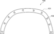
- FIG. 1 is an overall view schematically illustrating an example of a resin molded product according to the present disclosure.
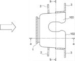
- FIG. 2 is a plan view of a clip seat in the resin molded product shown in FIG. 1.
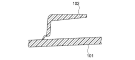
- FIG. 2B is a cross-sectional view taken along line aa of the clip seat shown in FIG. 2A. It is sectional drawing in the bb line of the clip seat shown in FIG. 2A.
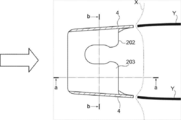
- FIG. 2B is a perspective view of the clip seat shown in FIG. 2A. It is a top view of the conventional clip seat.
- FIG. 3B is a cross-sectional view taken along line aa of the clip seat shown in FIG. 3A.
- FIG. 3B is a cross-sectional view of the clip seat shown in FIG. 3A along the line bb.
- the present invention is not limited to the following embodiments.
- the constituent elements including element steps and the like
- the term “step” includes, in addition to a step independent of other steps, even if the purpose of the step is achieved even if it cannot be clearly distinguished from the other steps, the step is also included.
- the numerical ranges indicated by using “to” include the numerical values described before and after “to” as the minimum value and the maximum value, respectively.
- the upper limit or lower limit described in one numerical range may be replaced with the upper limit or lower limit of another numerical range described in stages. Further, in the numerical range described in the present disclosure, the upper limit or the lower limit of the numerical range may be replaced with the value shown in the embodiment.
- the resin molded product of the present disclosure includes a main body, and a rib formed integrally with the main body, wherein the rib has a rib A provided in a direction along a resin flowing direction of the main body; It is a resin molded product including: a rib B provided in a direction intersecting the flow direction, on an upstream side of the rib A in the flow direction.
- FIG. 1 is an overall view schematically illustrating an example of a resin molded product according to the present disclosure, and is a diagram when a surface of a resin molded product on a side on which ribs are provided is observed.
- a resin molded product 100 shown in FIG. 1 includes a main body 101, and a clip seat 102 that includes a rib formed integrally with the main body 101 and is a component to be attached to a vehicle body.
- the resin molded product shown in FIG. 1 has the shape of an arch molding, which is an exterior part of an automobile, the resin molded product of the present disclosure is not limited thereto.
- the rib constitutes the clip seat, but the rib of the present disclosure is not limited to this.
- FIG. 2A is a plan view of the clip seat 102 in the resin molded product 100.
- the clip seat 102 shown in FIG. 2A includes a clip seat main body 103 and ribs 1 to 3 that are arranged on side surfaces of the clip seat main body 103 and connect the main body 101 and the clip seat main body 103.
- 2B is a cross-sectional view of the clip seat 102 and the main body 101 taken along the line aa of FIG. 2A
- FIG. 2C is a cross-sectional view of the clip seat 102 and the main body 101 taken along the line bb of FIG. 2A
- FIG. It is a perspective view of the clip seat shown to 2A.
- the resin flow direction is located upstream of a part (corresponding to rib A) of the rib 3 provided in the direction along the resin flow direction (indicated by a block arrow).
- a rib 2 (corresponding to a rib B) provided in a direction intersecting with.
- FIG. 3A is a plan view of a conventional clip seat 202.
- the side surface of the clip seat main body 203 serves as the rib 4 and connects the main body 201 and the clip seat main body 203.
- It has. 3B is a cross-sectional view of the clip seat 202 and the main body 201 taken along the line aa of FIG. 3A
- FIG. 3C is a cross-sectional view of the clip seat 202 and the main body 201 taken along the line bb of FIG. 3A.
- the resin flow direction and the rib 4 (corresponding to rib A) provided in the direction along the resin flow direction (indicated by block arrows) are provided. There are no ribs provided in the intersecting direction.
- a dent is formed in the portion corresponding to the rib 4 at the tip (indicated by the dotted line X) of the flowing resin. Is slower than the surroundings.
- a flow mark (indicated by a solid line Y) due to the difference in the flow speed of the resin is generated on the downstream side of the rib 4.
- the resin molded product provided with the clip seat 102 shown in FIG. 2A does not have a dent as shown in FIG.
- the flow velocity is kept constant.
- a flow mark as shown in FIG. 3A is unlikely to be generated on the downstream side of the rib 3, and it is considered that the appearance is favorably maintained.
- the “flow direction of the resin” means the direction in which the resin used for producing the resin molded product flows in the mold.
- the flow direction of the resin in the resin molded product can be confirmed, for example, by the position of the gate mark of the mold generated in the resin molded product. Alternatively, it can be confirmed by observing the state of the surface or cross section of the resin molded product.
- flow direction of resin means the flow direction of resin when passing over grooves corresponding to individual ribs, and may differ between ribs. Therefore, the flow direction of the resin in the resin molded article may be only one direction or a combination of a plurality of directions.
- rib A provided in a direction along the resin flow direction means a rib provided along a direction in which an angle to the flow direction of the resin is 0 ° or more and less than 40 °.
- the “rib B provided in a direction intersecting with the flow direction” means a rib provided along a direction in which the angle between the resin B and the flow direction is 60 ° to 90 °.
- the angle between the direction in which the ribs A are provided and the flow direction of the resin is preferably 0 ° to 20 °, and more preferably 0 ° to 10 °.
- the angle between the direction in which the ribs B are provided and the flow direction of the resin is preferably 75 ° to 90 °, and more preferably 80 ° to 90 °.
- the direction in which the ribs A and B (hereinafter, also referred to as ribs) are provided is determined based on the bottom of the rib (the portion where the rib rises from the main body of the resin molded product).
- the direction along the long side of the shape is defined as the direction in which the rib is provided.
- the direction along the maximum diameter of the bottom is defined as the direction in which the rib is provided.
- the shape of the bottom of the rib may be an I-shaped shape in which the whole faces in a direction along the flow direction of the resin or a direction intersecting the flow direction of the resin, or may be a shape other than the I-shape.
- a shape other than the I-shape a combination of I-shapes facing in different directions (L-shape, cross shape, etc.), a combination of an I-shape and a shape other than I-shape (U-shape, etc.) And the like.
- the direction in which the I-shape portion faces is the direction in which the rib is provided.
- the length of the I-shaped portion is defined as the length of the rib
- the width of the I-shaped portion is defined as the width of the rib.
- the rib A and the rib B may be in contact with each other or may be separated from each other. From the viewpoint of suppressing the appearance of the flow mark, the rib A and the rib B are preferably in contact with each other, or the distance between the rib A and the rib B is preferably 30 mm or less. More preferably, the distance between the rib A and the rib B is 10 mm or less. In the present disclosure, the distance between the rib A and the rib B means the distance between the rib A and the rib B closest to the rib A. Specifically, it means the length of the shortest line segment connecting the contour of the bottom of the rib A and the contour of the bottom of the rib B closest to the rib A.
- the number of ribs A and ribs B provided on the resin molded product is not particularly limited.
- the number of ribs B corresponding to one rib A may be one or more, and the number of ribs A corresponding to one rib B may be one or more. Good.
- the width of the rib A is preferably 2 mm or less, more preferably 1.5 mm or less, and even more preferably 1 mm or less.
- the width of the rib A is preferably 0.5 mm or more.
- the shorter the length of the rib A the better.
- the length of the rib A is preferably 100 mm or less, more preferably 70 mm or less, and even more preferably 50 mm or less.
- the length of the rib A is longer.
- the length of the rib A is preferably 2 mm or more, more preferably 5 mm or more.
- the height of the rib A is preferably 20 mm or less, and more preferably 15 mm or less.
- the higher the height of the rib A the more preferable.
- the height of the rib A is preferably 1 mm or more, more preferably 2 mm or more, even more preferably 5 mm or more.
- the rib B is provided in a direction intersecting with the flow direction of the resin, and the flow mark due to the rib B itself is hardly developed, and thus the shape is not particularly limited.
- the length of the rib B may be in a range from 5 mm to 100 mm.
- the width of the rib B may be in the range of 0.5 mm to 5 mm.
- the position where the rib is provided is not particularly limited.
- it when it is intended to be mounted on a vehicle body or the like, it is provided at a place where it is mounted on the vehicle body or the like. If the purpose is to reinforce the resin molded product, it is provided in a place where reinforcement is required.
- the thickness of the main body of the resin molded product (the minimum value of the thickness when the thickness is not constant) is not particularly limited, and can be selected according to the shape, application, and the like of the resin molded product. From the viewpoint of suppressing the appearance of the flow mark and securing the strength, it is preferable that the body of the resin molded product is thicker.
- the thickness of the main body (particularly, the thickness of the surface on which the rib is provided) is preferably 1 mm or more, and more preferably 2 mm or more.
- the thinner the main body of the resin molded product the better.
- the thickness of the main body is preferably 4 mm or less, more preferably 3 mm or less, and even more preferably 2.5 mm or less.
- the size of the resin molded product is not particularly limited. From the viewpoint of realizing the effect of realizing the thinning while maintaining the strength and maintaining the good appearance, for example, the area of the main surface (the surface having the largest area) is 180 cm 2 or more. You may.
- all the provided ribs may satisfy the above-described conditions of the ribs A and B, or some of the ribs may satisfy the above-described conditions of the ribs A and B.
- the rib provided in the portion where the appearance of the resin molded product is important may satisfy the above-described conditions of the rib A and the rib B.
- the resin molded article may be formed at least in part from a foamed resin. Since at least a part of the resin molded product is formed of the foamed resin, the weight of the resin molded product can be reduced even with the same thickness as compared with the case where the resin molded product is formed of the non-foamed resin. .
- the resin molded product is formed of foamed resin
- a portion close to the surface of the resin molded product is formed of non-foamed resin (skin layer), and the inside is formed of foamed resin. It may be.
- the production method is not particularly limited. For example, after filling a cavity (cavity) between a pair of molds including a movable mold and a fixed mold with a resin material containing a foaming agent, the movable mold is separated from the fixed mold. Moving the resin material (core back) to increase the volume of the void filled with the resin material, thereby foaming the resin material, and cooling in this state to produce a resin molded product that is a molded product of the foamed resin. (Injection foam molding).
- the rib can be integrally formed on the surface of the resin material main body. Further, by adjusting the moving distance of the movable mold, a resin molded product having a desired thickness can be manufactured.
- the resin used for manufacturing the resin molded product is not particularly limited.
- it can be selected from thermoplastic resins commonly used for injection molding.
- polyethylene resin, polypropylene resin, composite polypropylene resin, polystyrene resin, polyethylene terephthalate resin, polyvinyl alcohol resin, vinyl chloride resin, ionomer resin, polyamide resin, acrylonitrile butadiene styrene Copolymer resins and polycarbonate resins are exemplified.
- at least one selected from the group consisting of a polypropylene resin, a composite polypropylene resin, and an acrylonitrile-butadiene-styrene copolymer resin is preferable.
- the resin used in the production of the resin molded article may be only one kind or two or more kinds.
- the foaming agent examples include an organic foaming agent such as azodicarbonamide and an inorganic foaming agent such as sodium hydrogen carbonate (also known as sodium bicarbonate and sodium bicarbonate).
- an organic foaming agent is mainly used as a foaming agent, but from the viewpoint of improving coating film performance (such as hot water resistance), an organic foaming agent is preferable. .
- organic foaming agent examples include azodicarbonamide (ADCA), N, N-dinitrosopentamethylenetetramine (DPT), 4,4-oxybisbenzenesulfonylhydrazide (OBSH), and hydrazodicarbonamide (HDCA).
- ADCA azodicarbonamide
- DPT N, N-dinitrosopentamethylenetetramine
- OBSH 4,4-oxybisbenzenesulfonylhydrazide
- HDCA hydrazodicarbonamide
- ADCA azodicarbonamide
- the resin molded product of the present disclosure can be used for various applications. In particular, it can be suitably used for applications where the appearance of a resin molded product is important, for example, interior and exterior parts of automobiles. As interior and exterior parts of an automobile, an arch molding, a side molding, a rocker molding, a bumper, and the like can be given.
- the method of manufacturing a resin molded product according to the present disclosure includes a step of supplying a resin to a mold having a groove provided on an inner wall, wherein the groove is provided in a direction along a flow direction of the resin supplied to the mold.
- the resin molded product manufactured by the above method is provided integrally with the main body and has a rib having a shape corresponding to the shape of the groove provided on the inner wall of the mold. That is, the rib of the resin molded product satisfies the conditions of the rib A and the rib B in the resin molded product of the present disclosure described above. Therefore, in the resin molded product manufactured by the above method, the appearance of flow marks on the surface opposite to the surface on which the ribs are provided is suppressed, and a good appearance is maintained.
- the method for implementing the above method is not particularly limited.
- a general injection molding method may be used as a method for manufacturing a resin molded product.
- a manufacturing method in which at least a part of the resin is a foamed resin as described above may be used.
- a resin molded product was produced by injection foam molding using a resin material produced by mixing 100 parts by mass of a polypropylene resin and 2 parts by mass of azodicarbonamide (ADCA) as a foaming agent.
- ADCA azodicarbonamide
- a resin molded product was produced using the above-mentioned mold and resin material. At this time, the resin material was supplied from the gate provided in the mold so that the flow direction of the resin material when passing over the groove was in the direction of the arrow shown in FIGS. 2A and 3A.
- the molding conditions were a mold temperature of 50 ° C., a cylinder temperature of 220 ° C., a cooling time of 15 seconds, and a resin material temperature at the time of injection of 220 ° C.
- the thickness of the surface of the produced resin molded product on which the clip seat was provided was 3 mm.
- the width of the rib 1 in the clip seat 102 is 0.5 mm
- the width of a portion of the rib 2 along the flow direction of the resin is 0.9 mm
- the width of a portion of the rib 2 intersecting the flow direction of the resin is 0.1 mm.
- the width of the rib 3 was 0.9 mm
- the width of the rib 4 in the clip seat 202 was 0.8 mm.
Abstract
L'invention concerne un article moulé en résine qui est pourvu d'un corps principal et d'une nervure qui est moulée d'un seul tenant avec le corps principal, et qui est configurée de telle sorte que la nervure comprend une nervure A qui est disposée dans une direction qui s'étend le long de la direction d'écoulement de la résine du corps principal et une nervure B qui est disposée dans une direction qui croise la direction d'écoulement de façon à être positionnée en amont de la nervure A lorsqu'elle est vue depuis la direction d'écoulement.
Priority Applications (3)
| Application Number | Priority Date | Filing Date | Title |
|---|---|---|---|
| EP18924774.5A EP3792030A4 (fr) | 2018-06-29 | 2018-06-29 | Article moulé en résine et méthode de production d'article moulé en résine |
| PCT/JP2018/024936 WO2020003535A1 (fr) | 2018-06-29 | 2018-06-29 | Article moulé en résine et méthode de production d'article moulé en résine |
| JP2020527162A JP6973648B2 (ja) | 2018-06-29 | 2018-06-29 | 樹脂成形品及び樹脂成形品の製造方法 |
Applications Claiming Priority (1)
| Application Number | Priority Date | Filing Date | Title |
|---|---|---|---|
| PCT/JP2018/024936 WO2020003535A1 (fr) | 2018-06-29 | 2018-06-29 | Article moulé en résine et méthode de production d'article moulé en résine |
Publications (1)
| Publication Number | Publication Date |
|---|---|
| WO2020003535A1 true WO2020003535A1 (fr) | 2020-01-02 |
Family
ID=68984476
Family Applications (1)
| Application Number | Title | Priority Date | Filing Date |
|---|---|---|---|
| PCT/JP2018/024936 WO2020003535A1 (fr) | 2018-06-29 | 2018-06-29 | Article moulé en résine et méthode de production d'article moulé en résine |
Country Status (3)
| Country | Link |
|---|---|
| EP (1) | EP3792030A4 (fr) |
| JP (1) | JP6973648B2 (fr) |
| WO (1) | WO2020003535A1 (fr) |
Cited By (1)
| Publication number | Priority date | Publication date | Assignee | Title |
|---|---|---|---|---|
| CN114258226A (zh) * | 2021-12-31 | 2022-03-29 | 珠海格力电器股份有限公司 | 外观部件、家用电器及模具 |
Citations (7)
| Publication number | Priority date | Publication date | Assignee | Title |
|---|---|---|---|---|
| JPH0716876A (ja) * | 1993-06-30 | 1995-01-20 | Toyoda Gosei Co Ltd | リブを有するサンドイッチ成形品 |
| JP2005067564A (ja) * | 2003-08-28 | 2005-03-17 | Inoac Corp | サイドモール |
| JP2006231881A (ja) * | 2005-02-28 | 2006-09-07 | Kasai Kogyo Co Ltd | 自動車用内装部品及びその製造方法 |
| JP2012000843A (ja) * | 2010-06-16 | 2012-01-05 | Suzuki Motor Corp | 樹脂成形品 |
| JP2012188010A (ja) | 2011-03-10 | 2012-10-04 | Hayashi Engineering Inc | クリップ取付座、及び、内装材 |
| WO2014119751A1 (fr) * | 2013-02-02 | 2014-08-07 | コニカミノルタ株式会社 | Réseau de lentilles, système optique oculaire composite et procédé de production de l'ensemble de lentilles |
| JP2016043567A (ja) * | 2014-08-22 | 2016-04-04 | 三菱電機株式会社 | メタリック調樹脂成形品およびメタリック調樹脂成形品の製造方法 |
Family Cites Families (4)
| Publication number | Priority date | Publication date | Assignee | Title |
|---|---|---|---|---|
| JP4978117B2 (ja) * | 2006-08-28 | 2012-07-18 | スズキ株式会社 | 樹脂成形品 |
| JP2012171218A (ja) * | 2011-02-22 | 2012-09-10 | Panasonic Corp | 光輝材を有する熱可塑性樹脂の射出成形体の製造方法、及び射出成形体 |
| JP6011434B2 (ja) * | 2013-04-22 | 2016-10-19 | トヨタ車体株式会社 | 車両用樹脂部品及びその製造方法 |
| JP6454140B2 (ja) * | 2014-11-27 | 2019-01-16 | 日本プラスト株式会社 | 樹脂成形品 |
-
2018
- 2018-06-29 WO PCT/JP2018/024936 patent/WO2020003535A1/fr unknown
- 2018-06-29 JP JP2020527162A patent/JP6973648B2/ja active Active
- 2018-06-29 EP EP18924774.5A patent/EP3792030A4/fr active Pending
Patent Citations (7)
| Publication number | Priority date | Publication date | Assignee | Title |
|---|---|---|---|---|
| JPH0716876A (ja) * | 1993-06-30 | 1995-01-20 | Toyoda Gosei Co Ltd | リブを有するサンドイッチ成形品 |
| JP2005067564A (ja) * | 2003-08-28 | 2005-03-17 | Inoac Corp | サイドモール |
| JP2006231881A (ja) * | 2005-02-28 | 2006-09-07 | Kasai Kogyo Co Ltd | 自動車用内装部品及びその製造方法 |
| JP2012000843A (ja) * | 2010-06-16 | 2012-01-05 | Suzuki Motor Corp | 樹脂成形品 |
| JP2012188010A (ja) | 2011-03-10 | 2012-10-04 | Hayashi Engineering Inc | クリップ取付座、及び、内装材 |
| WO2014119751A1 (fr) * | 2013-02-02 | 2014-08-07 | コニカミノルタ株式会社 | Réseau de lentilles, système optique oculaire composite et procédé de production de l'ensemble de lentilles |
| JP2016043567A (ja) * | 2014-08-22 | 2016-04-04 | 三菱電機株式会社 | メタリック調樹脂成形品およびメタリック調樹脂成形品の製造方法 |
Non-Patent Citations (1)
| Title |
|---|
| See also references of EP3792030A4 * |
Cited By (2)
| Publication number | Priority date | Publication date | Assignee | Title |
|---|---|---|---|---|
| CN114258226A (zh) * | 2021-12-31 | 2022-03-29 | 珠海格力电器股份有限公司 | 外观部件、家用电器及模具 |
| CN114258226B (zh) * | 2021-12-31 | 2023-02-24 | 珠海格力电器股份有限公司 | 外观部件、家用电器及模具 |
Also Published As
| Publication number | Publication date |
|---|---|
| JP6973648B2 (ja) | 2021-12-01 |
| EP3792030A1 (fr) | 2021-03-17 |
| EP3792030A4 (fr) | 2021-05-26 |
| JPWO2020003535A1 (ja) | 2021-02-18 |
Similar Documents
| Publication | Publication Date | Title |
|---|---|---|
| US9636853B2 (en) | Molded body, method of manufacturing the same, seat material for vehicles, and method of manufacturing the same | |
| JP2007176021A (ja) | 成形品及びインサート成形方法 | |
| JP6264435B2 (ja) | 金型及び発泡成形体の製造方法 | |
| JP6866740B2 (ja) | シートクッション材の製造方法及びその製造用発泡型 | |
| JP7095252B2 (ja) | 樹脂成形品 | |
| JP2019064204A (ja) | 樹脂成形品 | |
| WO2020003535A1 (fr) | Article moulé en résine et méthode de production d'article moulé en résine | |
| JP2011025450A (ja) | 発泡成形品の製造方法及び発泡成形品 | |
| JP6915751B1 (ja) | 射出成形品及びその製造方法 | |
| JP6766868B2 (ja) | 樹脂成形品 | |
| US8535584B2 (en) | Method of manufacturing an automotive interior member | |
| JP2002225058A (ja) | 熱可塑性樹脂発泡成形体 | |
| JP2023055427A (ja) | 成形体、自動車用部材及び成形体の製造方法 | |
| JP2020131637A (ja) | 発泡樹脂成形用金型 | |
| JP7438415B2 (ja) | 車両用クッションパッド及びその製造方法 | |
| JP7001185B2 (ja) | 樹脂成形品 | |
| WO2024096031A1 (fr) | Moule et article moulé en résine | |
| WO2017154177A1 (fr) | Moulage de résine | |
| WO2024071426A1 (fr) | Produit moulé en mousse, élément de véhicule et porte arrière de véhicule | |
| WO2022149463A1 (fr) | Corps moulé, élément d'automobile et procédé de production pour corps moulé | |
| WO2024096033A1 (fr) | Produit moulé en résine | |
| WO2024096032A1 (fr) | Article en résine moulée | |
| JP2018001999A (ja) | モール樹脂部品 | |
| JPH0318567B2 (fr) | ||
| JP2023153879A (ja) | 車両用シートパッド及びその下層用の発泡体 |
Legal Events
| Date | Code | Title | Description |
|---|---|---|---|
| 121 | Ep: the epo has been informed by wipo that ep was designated in this application |
Ref document number: 18924774 Country of ref document: EP Kind code of ref document: A1 |
|
| ENP | Entry into the national phase |
Ref document number: 2020527162 Country of ref document: JP Kind code of ref document: A |
|
| ENP | Entry into the national phase |
Ref document number: 2018924774 Country of ref document: EP Effective date: 20201210 |
|
| NENP | Non-entry into the national phase |
Ref country code: DE |